EP3560701A1 - Verbundglas mit hohem brandwiderstand - Google Patents
Verbundglas mit hohem brandwiderstand Download PDFInfo
- Publication number
- EP3560701A1 EP3560701A1 EP19170615.9A EP19170615A EP3560701A1 EP 3560701 A1 EP3560701 A1 EP 3560701A1 EP 19170615 A EP19170615 A EP 19170615A EP 3560701 A1 EP3560701 A1 EP 3560701A1
- Authority
- EP
- European Patent Office
- Prior art keywords
- laminated glass
- fire
- glass
- facing
- laminated
- Prior art date
- Legal status (The legal status is an assumption and is not a legal conclusion. Google has not performed a legal analysis and makes no representation as to the accuracy of the status listed.)
- Granted
Links
Images

Classifications
-
- B—PERFORMING OPERATIONS; TRANSPORTING
- B32—LAYERED PRODUCTS
- B32B—LAYERED PRODUCTS, i.e. PRODUCTS BUILT-UP OF STRATA OF FLAT OR NON-FLAT, e.g. CELLULAR OR HONEYCOMB, FORM
- B32B17/00—Layered products essentially comprising sheet glass, or glass, slag, or like fibres
- B32B17/06—Layered products essentially comprising sheet glass, or glass, slag, or like fibres comprising glass as the main or only constituent of a layer, next to another layer of a specific material
- B32B17/069—Layered products essentially comprising sheet glass, or glass, slag, or like fibres comprising glass as the main or only constituent of a layer, next to another layer of a specific material of intumescent material
-
- C—CHEMISTRY; METALLURGY
- C03—GLASS; MINERAL OR SLAG WOOL
- C03B—MANUFACTURE, SHAPING, OR SUPPLEMENTARY PROCESSES
- C03B33/00—Severing cooled glass
- C03B33/07—Cutting armoured, multi-layered, coated or laminated, glass products
- C03B33/076—Laminated glass comprising interlayers
-
- E—FIXED CONSTRUCTIONS
- E06—DOORS, WINDOWS, SHUTTERS, OR ROLLER BLINDS IN GENERAL; LADDERS
- E06B—FIXED OR MOVABLE CLOSURES FOR OPENINGS IN BUILDINGS, VEHICLES, FENCES OR LIKE ENCLOSURES IN GENERAL, e.g. DOORS, WINDOWS, BLINDS, GATES
- E06B3/00—Window sashes, door leaves, or like elements for closing wall or like openings; Layout of fixed or moving closures, e.g. windows in wall or like openings; Features of rigidly-mounted outer frames relating to the mounting of wing frames
- E06B3/54—Fixing of glass panes or like plates
- E06B3/58—Fixing of glass panes or like plates by means of borders, cleats, or the like
- E06B3/62—Fixing of glass panes or like plates by means of borders, cleats, or the like of rubber-like elastic cleats
-
- E—FIXED CONSTRUCTIONS
- E06—DOORS, WINDOWS, SHUTTERS, OR ROLLER BLINDS IN GENERAL; LADDERS
- E06B—FIXED OR MOVABLE CLOSURES FOR OPENINGS IN BUILDINGS, VEHICLES, FENCES OR LIKE ENCLOSURES IN GENERAL, e.g. DOORS, WINDOWS, BLINDS, GATES
- E06B3/00—Window sashes, door leaves, or like elements for closing wall or like openings; Layout of fixed or moving closures, e.g. windows in wall or like openings; Features of rigidly-mounted outer frames relating to the mounting of wing frames
- E06B3/66—Units comprising two or more parallel glass or like panes permanently secured together
- E06B3/663—Elements for spacing panes
-
- E—FIXED CONSTRUCTIONS
- E06—DOORS, WINDOWS, SHUTTERS, OR ROLLER BLINDS IN GENERAL; LADDERS
- E06B—FIXED OR MOVABLE CLOSURES FOR OPENINGS IN BUILDINGS, VEHICLES, FENCES OR LIKE ENCLOSURES IN GENERAL, e.g. DOORS, WINDOWS, BLINDS, GATES
- E06B3/00—Window sashes, door leaves, or like elements for closing wall or like openings; Layout of fixed or moving closures, e.g. windows in wall or like openings; Features of rigidly-mounted outer frames relating to the mounting of wing frames
- E06B3/66—Units comprising two or more parallel glass or like panes permanently secured together
- E06B3/67—Units comprising two or more parallel glass or like panes permanently secured together characterised by additional arrangements or devices for heat or sound insulation or for controlled passage of light
- E06B3/6715—Units comprising two or more parallel glass or like panes permanently secured together characterised by additional arrangements or devices for heat or sound insulation or for controlled passage of light specially adapted for increased thermal insulation or for controlled passage of light
-
- E—FIXED CONSTRUCTIONS
- E06—DOORS, WINDOWS, SHUTTERS, OR ROLLER BLINDS IN GENERAL; LADDERS
- E06B—FIXED OR MOVABLE CLOSURES FOR OPENINGS IN BUILDINGS, VEHICLES, FENCES OR LIKE ENCLOSURES IN GENERAL, e.g. DOORS, WINDOWS, BLINDS, GATES
- E06B5/00—Doors, windows, or like closures for special purposes; Border constructions therefor
- E06B5/10—Doors, windows, or like closures for special purposes; Border constructions therefor for protection against air-raid or other war-like action; for other protective purposes
- E06B5/16—Fireproof doors or similar closures; Adaptations of fixed constructions therefor
- E06B5/164—Sealing arrangements between the door or window and its frame, e.g. intumescent seals specially adapted therefor
-
- E—FIXED CONSTRUCTIONS
- E06—DOORS, WINDOWS, SHUTTERS, OR ROLLER BLINDS IN GENERAL; LADDERS
- E06B—FIXED OR MOVABLE CLOSURES FOR OPENINGS IN BUILDINGS, VEHICLES, FENCES OR LIKE ENCLOSURES IN GENERAL, e.g. DOORS, WINDOWS, BLINDS, GATES
- E06B5/00—Doors, windows, or like closures for special purposes; Border constructions therefor
- E06B5/10—Doors, windows, or like closures for special purposes; Border constructions therefor for protection against air-raid or other war-like action; for other protective purposes
- E06B5/16—Fireproof doors or similar closures; Adaptations of fixed constructions therefor
- E06B5/165—Fireproof windows
-
- E—FIXED CONSTRUCTIONS
- E06—DOORS, WINDOWS, SHUTTERS, OR ROLLER BLINDS IN GENERAL; LADDERS
- E06B—FIXED OR MOVABLE CLOSURES FOR OPENINGS IN BUILDINGS, VEHICLES, FENCES OR LIKE ENCLOSURES IN GENERAL, e.g. DOORS, WINDOWS, BLINDS, GATES
- E06B5/00—Doors, windows, or like closures for special purposes; Border constructions therefor
- E06B5/20—Doors, windows, or like closures for special purposes; Border constructions therefor for insulation against noise
- E06B5/205—Doors, windows, or like closures for special purposes; Border constructions therefor for insulation against noise windows therefor
-
- E—FIXED CONSTRUCTIONS
- E06—DOORS, WINDOWS, SHUTTERS, OR ROLLER BLINDS IN GENERAL; LADDERS
- E06B—FIXED OR MOVABLE CLOSURES FOR OPENINGS IN BUILDINGS, VEHICLES, FENCES OR LIKE ENCLOSURES IN GENERAL, e.g. DOORS, WINDOWS, BLINDS, GATES
- E06B7/00—Special arrangements or measures in connection with doors or windows
- E06B7/28—Other arrangements on doors or windows, e.g. door-plates, windows adapted to carry plants, hooks for window cleaners
-
- B—PERFORMING OPERATIONS; TRANSPORTING
- B32—LAYERED PRODUCTS
- B32B—LAYERED PRODUCTS, i.e. PRODUCTS BUILT-UP OF STRATA OF FLAT OR NON-FLAT, e.g. CELLULAR OR HONEYCOMB, FORM
- B32B2307/00—Properties of the layers or laminate
- B32B2307/30—Properties of the layers or laminate having particular thermal properties
- B32B2307/306—Resistant to heat
- B32B2307/3065—Flame resistant or retardant, fire resistant or retardant
-
- B—PERFORMING OPERATIONS; TRANSPORTING
- B32—LAYERED PRODUCTS
- B32B—LAYERED PRODUCTS, i.e. PRODUCTS BUILT-UP OF STRATA OF FLAT OR NON-FLAT, e.g. CELLULAR OR HONEYCOMB, FORM
- B32B2605/00—Vehicles
-
- E—FIXED CONSTRUCTIONS
- E06—DOORS, WINDOWS, SHUTTERS, OR ROLLER BLINDS IN GENERAL; LADDERS
- E06B—FIXED OR MOVABLE CLOSURES FOR OPENINGS IN BUILDINGS, VEHICLES, FENCES OR LIKE ENCLOSURES IN GENERAL, e.g. DOORS, WINDOWS, BLINDS, GATES
- E06B3/00—Window sashes, door leaves, or like elements for closing wall or like openings; Layout of fixed or moving closures, e.g. windows in wall or like openings; Features of rigidly-mounted outer frames relating to the mounting of wing frames
- E06B3/54—Fixing of glass panes or like plates
- E06B3/58—Fixing of glass panes or like plates by means of borders, cleats, or the like
- E06B3/62—Fixing of glass panes or like plates by means of borders, cleats, or the like of rubber-like elastic cleats
- E06B2003/6238—Fixing of glass panes or like plates by means of borders, cleats, or the like of rubber-like elastic cleats having extra functions
- E06B2003/6244—Fixing of glass panes or like plates by means of borders, cleats, or the like of rubber-like elastic cleats having extra functions with extra parts sealing against the bottom of the glazing rebate or against the edge of the pane
Definitions
- This invention relates to a high fire resistant laminated glass, a method of manufacturing the laminated glass and its use in architecture, and in vehicle and aircraft construction. Also according to the invention is a fire protection system with the laminated glass and a frame.
- Laminated glasses with high fire resistance are known from the prior art. These laminated glasses generally have an intumescent layer in the form of a gel layer between two glass or glass ceramic panes, which foams when exposed to fire and in this way achieves insulation against thermal radiation.
- laminated glass There are basically two production variants of laminated glass to distinguish.
- the intumescent material which is still liquid during production, is poured onto one of the panes, where it is allowed to dry.
- the composite glasses thus obtained often have very thin gel layers ( ⁇ 2 mm) and usually have several such layers. Depending on their design, they can have very high fire resistance. They are then comparatively thick.
- a so produced laminated glass with a fire resistance of EW 120 will be well over 15 mm thick and correspondingly heavy.
- the two panes are placed parallel to each other, so that between the panes a gap is formed, which is sealed around with a seal.
- the still liquid intumescent material is poured into the gap, where it is usually chemically cured. This method is called cast in place method.
- no laminated glasses produced according to the second variant are available on the market, which have a fire resistance EW 120, can be cut and have a small thickness.
- GB 2 096 944 A relates to laminated glass with fire resistance.
- particularly thick glasses are recommended, because they should allow a higher stability and a greater fire resistance than thin glasses.
- tempered glasses can be used, since they have a higher breaking strength. Breaking strength plays a significant role in the identified fire resistance, as the breakage of the laminated glass panes results in the loss of fire resistance.
- the example described in the document with reference to Figure 4 has a thickness of 17.6 mm and withstood the fire test for only 50 minutes. It was therefore far from reaching a fire resistance of EW 120. All further attempts of the cited document achieve higher Fire resistance exclusively due to even higher composite thicknesses.
- the laminated glass of Example 4 described there achieves a resistance time of 90 minutes at a layer thickness of a stately 30 mm.
- EP 0 524 418 A1 also relates to composite glasses with fire resistance, which have a unilaterally roughened glass ceramic. Here, too, special attention is paid to the resistance to breakage in the event of fire.
- Example 1 a laminated glass 12 mm thick is tested. The cuttability is not discussed and a soda lime glass is used for both outer panes, which has a thermal expansion of well over 4 * 10 -6 / K.
- the other laminated glasses in this document have very large thicknesses. During firing, both soda lime glass outer panes break due to their high thermal expansion and organic parts (such as polyols) of the intumescent layer can ignite due to the air contact.
- EP 2 995 450 A1 also discloses laminated glasses with fire resistance.
- the laminated glasses described therein have thermally toughened discs with compressive stresses of at least 200 MPa.
- Thermally toughened discs of this type are not cuttable, but shatter when attempting to cut them.
- Cuttable laminated glass has the advantage that it does not have to be manufactured by the manufacturer to order, but can be prefabricated in large formats.
- the large-format laminated glass can then be cut to customer order and delivered, or the customer cuts the laminated glass itself as desired. In this way, a more economical production of large formats always the same size can be realized.
- laminated glasses which are relatively thin, since with a small thickness also low weight is associated, which is particularly important in vehicle and even more important in aircraft.
- the invention relates to a laminated glass with resistance to fire, with a brandabgewandten and a fire facing side, comprising at least two panes of float glass or floated glass ceramic, wherein the laminated glass contains at least one under the influence of temperature intumescent layer, which is preferably arranged between the two outer panes, wherein the Laminated glass each having an outer pane of float glass or gefloateram glass-ceramic on the fire-facing and on the fire-facing side as a final disc, the fire-facing and / or brand-facing outer pane has a thermal expansion coefficient ⁇ of at most 4.5 * 10 -6 / K or at most 4 * 10 -6 / K, and wherein the fire-facing outer pane has a thermal expansion coefficient ⁇ of at least 1 * 10 -6 / K.
- Float glass or floated glass ceramic is used according to the invention, since such disks have a particularly uniform, smooth surface. Floated discs have in particular fire polished surfaces with particularly low roughness.
- the outer facing facing the fire should have a thermal expansion coefficient ⁇ of at least 1 * 10 -6 / K, preferably at least 2 * 10 -6 / K.
- ⁇ thermal expansion coefficient
- a minimum value for the thermal expansion of the external facing facing the fire ensures that it breaks in the event of a fire after a relatively short time.
- the fracture of the outer facing of the fire relieves the laminated glass from the pressure created in the laminated glass by the high water content of the intumescent layer. If the outer facing facing the fire does not break under the influence of heat, there is the risk that the outer facing away from the fire breaks first under the influence of the pressure in the laminated glass, which would no longer give rise to fire resistance.
- the thermal expansion coefficient for the facing and / or the outer facing away from the fire is less than 4 * 10 -6 / K or less than 3.5 * 10 -6 / K.
- the thermal expansion coefficient for the facing and / or the brand-facing outer pane is 1 * 10 -6 / K to 4.5 * 10 -6 / K, in particular from 1.5 * 10 -6 / K to 4 * 10 . 6 / K or from 2 * 10 -6 / K to 3.5 * 10 -6 / K.
- a ceramic glass is used having a thermal expansion coefficient of less than 1 * 10 -6 / K, in particular less than 0.5 * 10 -6 / K, for the brand facing away from the outer pane.
- the thermal expansion coefficient may also be negative for glass-ceramic.
- a float glass is used both for the fire-facing and for the fire-facing outer pane with a thermal expansion coefficient in the range of 1 * 10 -6 / K to 4.5 * 10 -6 / K, in particular of 2 * 10 -6 / K to 3.5 * 10 -6 / K.
- the float glass in this case may be a borosilicate glass.
- a float glass with a thermal expansion coefficient of at least 1 ⁇ 10 -6 / K, in particular at least 3 ⁇ 10 -6 / K, at least 6 ⁇ 10 -6 / K or even at least 7, is used for the external facing glass * 10 -6 / K, and for the outer facing away from the fire, a floated glass-ceramic pane with a thermal expansion coefficient of less than 1 * 10 -6 / K, in particular less than 0.5 * 10 -6 / K, or a borosilicate glass with a coefficient of thermal expansion used by less than 4 * 10 -6 / K.
- the float glass for the outer facing of the fire can be a soda-lime glass or a borosilicate glass with a correspondingly large thermal expansion.
- laminated glass is understood to mean a composite of a plurality of glass and / or glass ceramic panes arranged essentially parallel to one another, each with at least one intermediate layer arranged between the panes.
- the discs and intermediate layers are processed so that they adhere to each other.
- adhesion promoters and / or adhesives are used which are known to the person skilled in the art for such purposes.
- the laminated glasses according to the invention are preferably monolithic, ie in particular have no space between the panes.
- outer pane refers to the panes of the laminated glass, which are arranged outside in the laminated glass and thus have an interface with the surrounding air with one of their main sides. This does not exclude according to the invention that the outer disks have one or more coatings.
- the "main sides" of a disk are the two largest sides of the disks in terms of area. In a preferred embodiment, the outer facing away from the fire and / or the outer facing the fire are uncoated.
- Fiber away is the outer pane of the laminated glass, which faces away from the expected fire when using the laminated glass.
- Brand facing is accordingly the side facing the expected fire. Therefore, according to the invention is also the use of the laminated glass described herein to achieve a fire barrier in case of fire on the side facing the fire.
- thermal expansion coefficient and “thermal expansion” are used synonymously in this application. This refers to the thermal expansion coefficient ⁇ over a temperature range of 20 to 300 ° C.
- the thermal coefficient of linear expansion can be determined, for example, according to DIN ISO 7991: 1998-02.
- the laminated glass of this invention has exactly two float glass or floated glass ceramic panes. In other words, such a laminated glass only has the two outer panes and no further glass or glass ceramic panes. In this way, a particularly thin laminated glass can be obtained. It is surprising that such high fire resistance can be achieved with the laminated glass according to the invention, although the number of layers and the thickness are small.
- the outer facing and / or the brand-facing outer pane has a temperature difference resistance (TUF) of more than 100 K, in particular more than 200 K.
- TEZ temperature difference resistance
- said temperature difference resistance is selected for the outer facing of the fire, and for the outer facing away from the fire a glass-ceramic pane. The measurement of the temperature difference resistance will be discussed below with reference to FIG. 3 explained.
- the outer facing and / or the brand-facing outer pane has a specific thermal stress of ⁇ 0.5 MPa / K, in particular ⁇ 0.3 MPa / K.
- said specific thermal stress is selected for the external facing facing the fire, and for the external facing facing away from the fire, a glass-ceramic facing.
- the outer facing and / or the brand-facing outer pane has a thickness in the range of 1 mm to 10 mm, in particular from 2 mm to 8 mm or from 3 mm to 5 mm.
- the thicknesses of the disks used in the laminated glass are as low as possible in order to achieve a composite which is as thin as possible, in particular, in one embodiment, none of the disks used is ⁇ 6 mm thick.
- the cuttability of the laminated glass deteriorates the thinner the discs used are.
- a certain minimum thickness is advantageous in order to achieve sufficient mechanical stability and sufficient fire resistance.
- Preferred laminated glasses have only glass or glass ceramic discs which are less than 10 mm, in particular less than 7 mm thick.
- the desired low total thickness can not be achieved. It has proven to be advantageous to select similar thicknesses for the fire-facing outer pane and the outer facing away from the fire.
- the difference in the thicknesses of these two discs with respect to the thinner disc relative to the thicker disc is at most 33%, in particular at most 25% or at most 20%.
- the two discs are approximately the same thickness, ie the thinner disc is thinner than the thicker disc at most 10%, in particular at most 5% or at most 2.5% thinner.
- the laminated glasses of this invention have an intumescent interlayer, which is preferably a polysilicate interlayer.
- the content of polyols in the intumescent interlayer should not exceed a value of 10% by weight. Containing too high levels of polyols, curing and UV stability may be impaired or may result in haze or discoloration.
- Preferred polysilicates are alkali polysilicates, in particular potassium polysilicate. Intumescent layers with potassium polysilicate can be carried out in the cast in place process with very low layer thicknesses, so that the selection of these polysilicates is advantageous for the production of particularly thin laminated glass.
- the layer thickness of the intumescent layer is preferably 1 mm to 10 mm, in particular up to 8 mm, or up to 5 mm, but preferably only up to 3 mm. It has surprisingly been found that even with such low layer thicknesses, very high fire resistance can be achieved.
- the outer facing and / or brand facing outer pane is chemically biased.
- Chemical biasing methods are known to those skilled in the art. They induce compressive stress by replacing smaller ions with larger ones. In this way, the breaking strength of a disc is increased. It has been found that a chemical preload is possible without impairing the cuttability, in particular when the compressive stress on the surface of the chemically tempered disc is not more than 1000 MPa, not more than 800 MPa, not more than 600 MPa, in particular not more than 400 MPa, and more preferably less than 200 MPa.
- the term "thermally toughened” is understood according to the invention to mean a disk which, due to thermal prestressing, has a compressive stress on its surface of more than 200 MPa.
- the laminated glass of this invention preferably does not have thermally toughened disks because they are not cuttable.
- the outer facing and / or the brand-facing outer pane is a glass-ceramic pane, wherein it is preferred according to the invention that in this embodiment only one of the two outer panes, in particular only the outer pan facing away from the fire, is a glass-ceramic pane.
- a glass-ceramic pane is a particularly low thermal expansion it is not guaranteed that they will be destroyed by heat and thus a pressure relief is made possible. If glass ceramic panes with very low thermal expansion are used both on the side facing away from the fire and on the side facing away from the fire, it can happen in the worst case that the outer pane facing away from the fire first breaks in the event of fire, so that sufficient fire resistance can no longer be achieved.
- the laminated glass of the present invention is intended to be cuttable.
- "Cuttable" means according to the invention that the laminated glass can be divided by means of water jet cutting and / or sawing into smaller parts, without causing the outer disks to break. Preference is given to water-jet cutting, since better cut edges can be achieved in this way.
- the water jet cutting is carried out at a pressure of 1,000 to 5,000 bar, in particular from 2,000 to 4,000 bar. It may preferably be a garnet sand addition, in particular in an amount of 3 to 40 kg / h.
- the cutting speed should preferably be in the range of 50 to 1,000 mm / min.
- Water jet cutting is particularly suitable for cutting chemically tempered glasses. For sawing in particular a diamond saw blade should be used. It is preferably sawn at a feed rate of 300 to 500 mm / min.
- the invention also provides a laminated glass in which the bending tensile strength of the outer facing and / or the outer facing away from the fire is ⁇ 100 N / mm 2 or ⁇ 140 N / mm 2 .
- the bending tensile strength can be determined according to DIN EN 1288-3: 2000-09.
- High flexural tensile strengths of the outer panes used have the advantage that the laminated glass obtains a high mechanical stability or relatively thin panes can be used.
- a preferred embodiment of the invention can be realized, in which the laminated glass has a thickness of less than 20 mm, in particular less than 15 mm or even less than 13 mm.
- Cuttable laminated glasses of the prior art with similar fire resistance as the invention are generally much thicker, in particular thicker than 20 mm. Cuttable thin glasses are not available on the market, probably due to lack of reliability in the fire test. Commercially available cuttable glasses with EW 120 are over 50 mm thick. Of course, the laminated glasses of this invention must have a certain minimum thickness to achieve the required properties in the With regard to the fire resistance. Therefore, the laminated glasses of this invention are preferably at least 7 mm, at least 8 mm or at least 10 mm thick.
- the laminated glass includes an edge seal to prevent the properties of the intumescent layer from changing over time.
- the distance between the intumescent layer and the edge of the laminated glass at least one, in particular at least two sides, a maximum of 5 mm.
- a less wide seal is needed to protect the intumescent layer from environmental influences, a certain minimum width, e.g. but at least 1 mm or at least 3 mm are advantageous.
- the width of the gasket is its extent parallel to the major sides of the outer discs and perpendicular to the longitudinal course of the edge sealed with the gasket. Cut glass rims can be sealed with relatively narrow seals, e.g. with polysulfide seals.
- Float glass is used as the glass pane for the fire-facing and / or brand-facing outer pane.
- Preferred float glass is borosilicate glass or soda lime glass. Soda lime glass can be used in particular as a fire-facing outer pane together with glass ceramic as a fire-facing outer pane.
- Particularly preferred is borosilicate glass, because this is obtainable with the desired properties described herein, in particular the thermal expansion coefficient.
- borosilicate glass panes which have a content of SiO 2 of at least 78 mole percent. Borosilicate glasses with lower proportions of this component often show significantly higher thermal expansion coefficients. For the same reason, the content of alkali metal oxides in the preferred borosilicate glasses is more preferably at most 9 mole percent, preferably at most 8 mole percent or at most 7 mole percent. The content of alkali metal oxides has a particularly large influence on the thermal expansion coefficient. Preferred borosilicate glasses contain Na 2 O in a greater proportion than K 2 O, because a better chemical prestressability can be achieved thereby.
- borosilicate glasses include the components listed in the following table in the ranges specified therein in mole percent. min Max SiO 2 78 86 B 2 O 3 8th 17 Al 2 O 3 > 0 4 Na 2 O 1 6 K 2 O > 0 3 CaO 0 2 total 100 100
- the laminated glass according to the invention can be achieved using suitable, known in the art frame structures particularly good fire resistance, in particular fire resistance EW 120 according to DIN EN 13501-2: 2016.
- this fire resistance is achieved up to a size of the laminated glass of 2 m 2 , in particular to 3 m 2 or 4 m 2 .
- the material of the fire-facing and / or brand-facing outer pane has a softening point of at least 800 ° C.
- the "softening point” is the temperature at which the material has a viscosity of at least 10 7.6 dPas.
- the softening point can be determined according to DIN ISO 7884-6 Glass Viscosity and Viscosimetric Test Points - Part 6: Determination of the softening temperature (ISO 7884-6: 1987).
- a fire protection system with a laminated glass as described above and a frame in which the laminated glass is enclosed.
- a fire protection system is suitable for use as a window, door or fixed glazing, for example in architecture, vehicle and aircraft.
- the fire protection systems of this invention preferably consist essentially of laminated glass, frames, gaskets and fittings.
- Laminated glass of different construction and thickness can be used for the different fire protection classes and if necessary to achieve additional properties (heat transfer, sound insulation, burglar resistance, etc.). Accordingly, frames made of different materials (wood, aluminum, steel + combinations) and design (pipe, drawn profiles, thermally separated, etc.) can be selected.
- Steel frame systems are preferred for the present invention because they are particularly suitable for a long service life.
- the steel frame system consists of a circumferential profile, in the simplest case of tubular steel.
- the profile can be designed as a stop profile.
- the profile can be made thermally separated.
- the laminated glass is fixed between the stop and the glazing beads or only between glazing beads.
- thermally-separated or cooled-filled frames can be used.
- Fire protection systems achieve a fire resistance, in particular at least EW 120.
- the frame comprises a steel frame system for E / EW 120.
- Trial and measurement are carried out according to the standards DIN EN 1363 / EN 1364. The test results then allow a classification EW 120 according to DIN EN 13501-2: 2016th
- the invention also relates to the use of the laminated glass described herein and the fire protection system as architectural or vehicle glazing, in particular in land, air or water vehicles.
- the manufacturing process is therefore a cast in place process.
- the intermediate space between the two essentially parallel panes does not necessarily have to be formed by the two outer panes, but can also be formed, for example, by two inner panes of the laminated glass, which are not the outer panes.
- a the two substantially parallel discs which form the space be an outer disc and the other an internal disc of the laminated glass. In a preferred embodiment, however, the gap is formed between the two outer panes.
- the cutting of the laminated glass is preferably carried out by water jet cutting or sawing. These two methods are generally known to the person skilled in the art for the cutting of glasses and, surprisingly, the usual methods can be used without special precautions.
- the water jet cutting is carried out at a pressure of 1,000 to 5,000 bar, in particular from 2,000 to 4,000 bar. It may preferably be a garnet sand addition, in particular in an amount of 3 to 40 kg / h.
- the cutting speed should preferably be in the range of 50 to 1,000 mm / min.
- Water jet cutting is particularly suitable for cutting chemically tempered glasses. For sawing in particular a diamond saw blade should be used. It is preferably sawn at a feed rate of 300 to 500 mm / min.
- a non-cut to shape in-place laminated glass has the edge seal applied during the manufacturing process and therefore need not be further sealed.
- the laminated glasses according to the invention can be cut and should therefore be subsequently sealed again in order to protect the cut edges and in particular the intumescent layer from environmental influences.
- FIG. 1 shows a fire protection system according to the invention with a laminated glass 1 and a frame 5, in which the laminated glass 1 is enclosed.
- the laminated glass 1 comprises two outer panes 2, one of which faces the fire 4 and faces away from the fire 4.
- the laminated glass 1 has an edge seal 6, which prevents leakage of the intumescent material of the intumescent layer 3 during manufacture.
- the laminated glass 1 has edges 7 on the smallest sides in terms of area.
- the intumescent layer 3 is spaced in this embodiment from the edges 7 due to the arrangement of the edge seal 6 between the discs.
- the brand-facing and fire-facing outer panels 2 may consist of similar material and thus form a symmetrical composite; or they can be made of different materials and represent an asymmetric bond. It is according to the invention required that the fire 4 facing outer pane 2 has a coefficient of thermal expansion of at least 1 * 10 -6 / K, to ensure that this disc breaks in case of fire. To illustrate the desired fraction of the fire 4 facing outer pane 2 cracks 8 are shown in the figure. The fire 4 facing away from the outer pane 2, however, shows no such cracks. The outer pane 2 facing away from the fire 4 should have a very low coefficient of thermal expansion of at most 4.5 * 10 -6 / K so that it withstands the heat of the fire 4 as long as possible.
- thermal expansion plays a decisive role. Due to the rapid increase in the unit temperature-time curve and the possible occurrence of hot spots, the disc is subject to high temperature differences. At the end of the fire test, it is a high softening point, which promises a long service life.
- the outer pane 2 facing away from the fire 4 is a floated glass ceramic pane or a floated borosilicate glass pane with low thermal expansion and the outer pane 2 facing the fire 4 is a float glass pane, such as a floated soda lime glass pane or borosilicate glass pane.
- both the outer pane 2 facing away from the fire 4 and the outer pane 2 facing the fire 4 are a floated borosilicate glass pane.
- the intended for the outer panes 2 floated glass and glass ceramic discs are preferably not thermally biased because thermally toughened discs are difficult or impossible to cut at all.
- one of the outer panes 2 or both may be chemically tempered. It has been found that chemically toughened borosilicate glass panes are surprisingly cuttable.
- FIG. 2 shows an alternative embodiment of a laminated glass according to the invention with two outer panes 2, between which an intumescent layer 3 is arranged.
- the edge seal 6 is formed in this case by a thin layer which may be formed as a plastic or metal foil, in particular aluminum foil.
- the edge seal 6 preferably encloses the entire edge 7 of the laminated glass 1 and may extend to the outer sides of the outer panes 2 for better sealing.
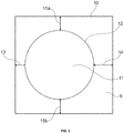
- FIG. 3 illustrates the determination of the temperature difference resistance.
- the temperature differential strength indicates the resistance of a glass sheet to temperature differences between the hot, middle and cold outer edges.
- the square test format is 250 mm x 250 mm.
- the disks are pre-damaged in order to simulate the later state of use of the surface.
- the surface is treated with emery of 220 grit according to DIN 69176 Part 2.
- the surface pressure during the emery process is 2.0 ⁇ 0.2 N / cm 2 .
- the emery direction is perpendicular to the disc outer edges.
- the test is done in a horizontal position of the test disc in an arrangement FIG. 3 ,
- the test of the disc 9 is carried out by one-sided heating of a circular central region 11 of the scholar 9.
- the diameter of the heated circular surface 11 is 175 mm.
- the center of the circle is acentric and after FIG. 3 chosen so that different distances of the edge 12 of the heated circular area of the outer edge 10 exist, wherein the minimum distance 13 to an outer edge is 25 mm, the distance 14 to the opposite outer edge, however, 50 mm.
- the distance 15a and 15b to the other two edges is consistently 37.5 mm.
- the edge area of the test disc is kept at a low temperature of 25 ⁇ 5 ° C, for example by a metal support frame.
- the heating is temperature controlled until the disc breaks, which usually occurs at the location of the largest temperature gradient, i. in the area of the outer edge with the smallest distance to the heated center area.
- the temperature control ensures a break within a heating time of 5 ⁇ 1 minutes.
- the indicator for the temperature difference resistance is the maximum temperature reached at the time of breakage of the test disk on the side of the disk opposite the heating.
- the laminated glass was produced by the cast in place process with a 10 mm wide seal. The size was 1 mx 2 m.
- a fire test was carried out with the laminated glass in a steel frame and a glass strip attached to the fire. The brand-facing outer pane broke in the first minute of the test. The heat transfer was 12 kW / m 2 in the 120 minutes and remained below the limit of 15 kW / m 2 . A fire resistance of EW 120 is thus achieved.
- the laminated glass was produced by the cast in place process and then cut to a size of 1 mx 2 m.
- a fire test was carried out with the laminated glass in a steel frame and glass strips on both sides. The brand-facing outer pane broke in the first minute of the test. The heat transfer was 11 kW / m 2 in the 120 minutes and thus remained below the limit of 15 kW / m 2 . A fire resistance of EW 120 is thus achieved.
- the laminated glass was produced by the cast in place process with a 10 mm wide seal. The size was 1 mx 2.3 m.
- a fire test was carried out with the laminated glass in a steel frame and glass strips on both sides. The brand-facing outer pane broke in the first minute of the test. The heat transfer was ⁇ 15 kW / m 2 in the 120 minutes and thus remained below the limit of 15 kW / m 2 . A fire resistance of EW 120 is thus achieved.
- the laminated glass was produced by the cast in place process and then cut to a size of 0.5 mx 0.5 m. The cut edges were sealed with an aluminum tape.
- a fire test was carried out with the laminated glass in a thermally insulated steel frame and glass bar attached to the air side. The brand-facing outer pane broke in the second minute of the test. The heat transfer was ⁇ 3 kW / m 2 in the 120 minutes and thus remained very clearly below the limit of 15 kW / m 2 . A fire resistance of EW 120 is thus achieved.
- the laminated glass was produced by the cast in place process and then cut to a size of 0.5 mx 0.5 m. The cut edges were sealed with a polysulfide seal.
- a fire test was carried out with the laminated glass in a steel frame and glass strip attached to the air. The brand-facing outer pane broke in the second minute of the test. The heat transfer was ⁇ 3 kW / m 2 in the 120 minutes and thus remained very clearly below the limit of 15 kW / m 2 . A fire resistance of EW 120 is thus achieved.
Landscapes
- Engineering & Computer Science (AREA)
- Civil Engineering (AREA)
- Structural Engineering (AREA)
- Chemical & Material Sciences (AREA)
- Materials Engineering (AREA)
- Organic Chemistry (AREA)
- Joining Of Glass To Other Materials (AREA)
- Special Wing (AREA)
Abstract
Description
- Diese Erfindung betrifft ein Verbundglas mit hohem Brandwiderstand, ein Herstellungsverfahren für das Verbundglas und dessen Verwendung in der Architektur sowie im Fahrzeug- und Flugzeugbau. Erfindungsgemäß ist auch ein Brandschutzsystem mit dem Verbundglas und einem Rahmen.
- Verbundgläser mit hohem Brandwiderstand sind aus dem Stand der Technik bekannt. Diese Verbundgläser weisen in der Regel eine Intumeszenzschicht in Form einer Gelschicht zwischen zwei Glas- oder Glaskeramikscheiben auf, die bei Brandeinwirkung aufschäumt und auf diese Weise eine Isolation gegen Wärmestrahlung erzielt. Dabei sind grundsätzlich zwei Fertigungsvarianten von Verbundgläsern zu unterscheiden. In einer ersten Variante wird das während der Herstellung noch flüssige Intumeszenzmaterial auf eine der Scheiben aufgegossen, wo es trocknen gelassen wird. Die so erhältlichen Verbundgläser haben oft sehr dünne Gelschichten (<2 mm) und weisen meistens mehrere solcher Schichten auf. Sie können je nach Aufbau sehr hohe Brandwiderstände aufweisen. Sie sind dann aber vergleichsweise dick. Ein so hergestelltes Verbundglas mit einem Brandwiderstand von EW 120 wird deutlich über 15 mm dick sein und entsprechend schwer. In einer zweiten Variante werden die beiden Scheiben parallel zueinander aufgestellt, sodass sich zwischen den Scheiben ein Zwischenraum bildet, der rundherum mit einer Dichtung abgedichtet wird. Durch eine Öffnung in der Randdichtung wird das noch flüssige Intumeszenzmaterial in den Zwischenraum gegossen, wo es in der Regel chemisch ausgehärtet wird. Dieses Verfahren wird Cast in place-Verfahren genannt. Derzeit sind keine nach der zweiten Variante hergestellten Verbundgläser auf dem Markt verfügbar, die einen Brandwiderstand EW 120 aufweisen, schneidbar sind und eine geringe Dicke haben.
-
GB 2 096 944 A -
EP 0 524 418 A1 betrifft ebenfalls Verbundgläser mit Brandwiderstand, die eine einseitig aufgeraute Glaskeramik aufweisen. Auch hier wird ein besonderes Augenmerk auf die Bruchfestigkeit im Brandfall gelegt. In Beispiel 1 wird ein Verbundglas mit 12 mm Dicke getestet. Die Schneidbarkeit wird nicht diskutiert und es wird für beide Außenscheiben ein Kalknatronglas verwendet, das eine thermische Ausdehnung von deutlich über 4*10-6 /K aufweist. Die anderen Verbundgläser in diesem Dokument haben sehr große Dicken. Beim Brand brechen beide Kalknatronglas-Außenscheiben aufgrund ihrer hohen thermischen Ausdehnung und organische Anteile (wie Polyolen) der Intumeszenzschicht können sich aufgrund des Luftkontakts entzünden. - Auch
US 6,379,825 B1 beschreibt Verbundgläser mit Brandschutzwirkung. Allerdings erreichen diese auch bei Verbunddicken von teilweise deutlich über 15 mm nicht den geforderten Brandwiderstand von EW 120. -
EP 2 995 450 A1 offenbart ebenfalls Verbundgläser mit Brandwiderstand. Die dort beschriebenen Verbundgläser weisen allerdings thermisch vorgespannte Scheiben auf mit Druckspannungen von wenigstens 200 MPa. Thermisch vorgespannte Scheiben dieser Art sind nicht schneidbar, sondern zerspringen beim Versuch, diese zu zerschneiden. - Es wäre wünschenswert, ein Verbundglas mit hohem Brandwiderstand, insbesondere Brandwiderstand von mindestens EW 120, zu haben, das bei sehr geringer Dicke dennoch schneidbar ist. Schneidbare Verbundgläser haben den Vorteil, dass sie beim Hersteller nicht erst auf Bestellung gefertigt werden müssen, sondern in großen Formaten vorgefertigt werden können. Die großformatigen Verbundgläser können dann auf Kundenbestellung zugeschnitten und ausgeliefert werden, oder der Kunde schneidet die Verbundgläser selbst nach Wunsch zu. Auf diese Weise lässt sich eine wirtschaftlichere Fertigung großer Formate stets gleicher Größe realisieren. Besonders vorteilhaft sind dabei natürlich Verbundgläser, die verhältnismäßig dünn sind, da mit geringer Dicke auch geringes Gewicht einhergeht, was besonders im Fahrzeugbau und noch mehr im Flugzeugbau von Bedeutung ist.
- Die Gegenstände der Patentansprüche zeigen die gewünschten Eigenschaften.
- Die Erfindung betrifft ein Verbundglas mit Widerstand gegen Brandwirkung, mit einer brandabgewandten und einer brandzugewandten Seite, umfassend mindestens zwei Scheiben aus Floatglas oder gefloateter Glaskeramik, wobei das Verbundglas zumindest eine unter Temperatureinwirkung intumeszierende Schicht enthält, die vorzugsweise zwischen den beiden Außenscheiben angeordnet ist, wobei das Verbundglas je eine Außenscheibe aus Floatglas oder gefloateter Glaskeramik auf der brandabgewandten und auf der brandzugewandten Seite als abschließende Scheibe aufweist, wobei die brandzugewandte und/oder die brandabgewandte Außenscheibe einen thermischen Ausdehnungskoeffizienten α von höchstens 4,5*10-6 /K oder höchstens 4*10-6 /K aufweist, und wobei die brandzugewandte Außenscheibe einen thermischen Ausdehnungskoeffizienten α von wenigstens 1*10-6 /K aufweist.
- Floatglas bzw. gefloatete Glaskeramik wird erfindungsgemäß eingesetzt, da solche Scheiben eine besonders gleichförmige, glatte Oberfläche haben. Gefloatete Scheiben weisen insbesondere feuerpolierte Oberflächen mit besonders geringer Rauheit auf.
- Dieser erfindungsgemäße Aufbau eines Verbundglases hat sich als besonders vorteilhaft erwiesen. Im Stand der Technik wird oftmals empfohlen, die thermische Ausdehnung der verwendeten Scheiben so gering wie möglich zu halten. Dies ist allerdings nicht unter allen Umständen vorteilhaft. Erfindungsgemäß soll die brandzugewandte Außenscheibe einen thermischen Ausdehnungskoeffizienten α von wenigstens 1*10-6 /K, vorzugsweise wenigstens 2*10-6 /K, aufweisen. Durch einen Mindestwert für die thermische Ausdehnung der brandzugewandten Außenscheibe wird sichergestellt, dass diese im Brandfalle nach relativ kurzer Zeit bricht. Der Bruch der brandzugewandten Außenscheibe entlastet das Verbundglas von dem Druck, der in dem Verbundglas durch den hohen Wassergehalt der intumeszierenden Schicht entsteht. Bricht die brandzugewandten Außenscheibe nicht unter Hitzeeinwirkung, so besteht das Risiko, das die brandabgewandte Außenscheibe unter dem Einfluss des Druckes in dem Verbundglas zuerst bricht, wodurch kein Brandwiderstand mehr gegeben wäre.
- In einer erfindungsgemäß bevorzugten Ausführungsform beträgt der thermische Ausdehnungskoeffizient für die brandzugewandte und/oder die brandabgewandte Außenscheibe weniger als 4*10-6 /K oder weniger als 3,5*10-6 /K. In einer Ausführungsform beträgt der thermische Ausdehnungskoeffizient für die brandzugewandte und/ oder die brandabgewandte Außenscheibe 1*10-6 /K bis 4,5*10-6 /K, insbesondere von 1,5*10-6 /K bis 4*10-6 /K oder von 2*10-6 /K bis 3,5*10-6 /K. In einer Ausführungsform wird für die brandabgewandte Außenscheibe eine Glaskeramikscheibe mit einem thermischen Ausdehnungskoeffizienten von weniger als 1*10-6 /K, insbesondere weniger als 0,5*10-6 /K, verwendet. Der thermische Ausdehnungskoeffizient kann bei Glaskeramik auch negativ sein.
- In einer symmetrischen Ausführungsform des erfindungsgemäßen Verbundglases wird sowohl für die brandzugewandte als auch für die brandabgewandte Außenscheibe ein Floatglas verwendet mit einem thermischen Ausdehnungskoeffizienten im Bereich von 1*10-6 /K bis 4,5*10-6 /K, insbesondere von 2*10-6 /K bis 3,5*10-6 /K. Das Floatglas kann in diesem Fall ein Borosilicatglas sein. Auf diese Weise wird sichergestellt, dass die brandzugewandte Außenscheibe im Brandfall rechtzeitig bricht und die Bruchfestigkeit unter Temperaturbelastung ausreichend groß ist, um der Hitzeeinwirkung für einen langen Zeitraum standzuhalten.
- In einer asymmetrischen Ausführungsform des erfindungsgemäßen Verbundglases wird für die brandzugewandte Außenscheibe ein Floatglas mit einem thermischen Ausdehnungskoeffizienten von wenigstens 1*10-6 /K, insbesondere wenigstens 3*10-6 /K, wenigstens 6*10-6 /K oder sogar wenigstens 7*10-6 /K, und für die brandabgewandte Außenscheibe eine gefloatete Glaskeramikscheibe mit einem thermischen Ausdehnungskoeffizienten von weniger als 1*10-6 /K, insbesondere weniger als 0,5*10-6 /K, oder ein Borosilicatglas mit einem thermischen Ausdehnungskoeffizienten von weniger als 4*10-6 /K verwendet. Das Floatglas für die brandzugewandte Außenscheibe kann in diesem Fall ein Kalknatronglas oder ein Borosilicatglas mit entsprechend großer thermischer Ausdehnung sein.
- Unter "Verbundglas" wird erfindungsgemäß ein Verbund mehrerer im Wesentlichen parallel zueinander angeordneter Glas- und/oder Glaskeramikscheiben mit jeweils wenigstens einer zwischen den Scheiben angeordneter Zwischenschicht verstanden. Die Scheiben und Zwischenschichten werden so verarbeitet, dass sie aneinander haften. Dafür werden gegebenenfalls Haftvermittler und/oder Klebstoffe eingesetzt, die dem Fachmann für solche Zwecke bekannt sind. Die erfindungsgemäßen Verbundgläser sind vorzugsweise monolithisch, haben also insbesondere keinen Scheibenzwischenraum.
- Als "Außenscheibe" werden die Scheiben des Verbundglases bezeichnet, die im Verbundglas außen angeordnet sind und somit mit einer ihrer Hauptseiten eine Grenzfläche zur umgebenden Luft aufweisen. Dies schließt erfindungsgemäß nicht aus, dass die Außenscheiben eine oder mehrere Beschichtungen aufweisen. Die "Hauptseiten" einer Scheibe sind die beiden hinsichtlich der Fläche größten Seiten der Scheiben. In einer bevorzugten Ausführungsform sind die brandabgewandte und/oder die brandzugewandte Außenscheibe unbeschichtet.
- "Brandabgewandt" ist diejenige Außenscheibe des Verbundglases, die bei der Verwendung des Verbundglases von dem erwarteten Brand abgewandt ist. "Brandzugewandt" ist entsprechend die dem erwarteten Brand zugewandte Seite. Erfindungsgemäß ist daher auch die Verwendung der hierin beschriebenen Verbundgläser zur Erzielung einer Brandbarriere bei Brandeinwirkung auf die brandzugewandte Seite.
- Die Begriffe "thermischer Ausdehnungskoeffizient" und "thermische Ausdehnung" werden in dieser Anmeldung synonym verwendet. Gemeint ist der thermische Längenausdehnungskoeffizient α über einen Temperaturbereich von 20 bis 300 °C. Der thermische Längenausdehnungskoeffizient kann beispielsweise gemäß DIN ISO 7991:1998-02 bestimmt werden.
- In einer Ausführungsform weist das Verbundglas dieser Erfindung genau zwei Floatglas- bzw. gefloatete Glaskeramikscheiben auf. Mit anderen Worten weist ein solches Verbundglas nur die beiden Außenscheiben auf und keine weiteren Glas- oder Glaskeramikscheiben. Auf diese Weise kann ein besonders dünnes Verbundglas erhalten werden. Es ist erstaunlich, dass sich mit dem erfindungsgemäßen Verbundglas derart hohe Brandwiderstände erzielen lassen, obwohl die Schichtanzahl und Dicke gering sind.
- In einer Ausführungsform weist die brandzugewandte und/oder die brandabgewandte Außenscheibe eine Temperaturunterschiedsfestigkeit (TUF) von mehr als 100 K, insbesondere von mehr als 200 K, auf. In einer Ausführungsform wird die genannte Temperaturunterschiedsfestigkeit für die brandzugewandte Außenscheibe gewählt und für die brandabgewandte Außenscheibe eine Glaskeramikscheibe. Die Messung der Temperaturunterschiedsfestigkeit wird weiter unten mit Bezug zu
Figur 3 erläutert. - In einer Ausführungsform weist die brandzugewandte und/oder die brandabgewandte Außenscheibe eine spezifische Wärmespannung von <0,5 MPa/K, insbesondere <0,3 MPa/K, auf. In einer Ausführungsform wird die genannte spezifische Wärmespannung für die brandzugewandte Außenscheibe gewählt und für die brandabgewandte Außenscheibe eine Glaskeramikscheibe. Die spezifische Wärmespannung ϕ ist definiert als:

- In einer Ausführungsform weist die brandzugewandte und/oder die brandabgewandte Außenscheibe eine Dicke im Bereich von 1 mm bis 10 mm, insbesondere von 2 mm bis 8 mm oder von 3 mm bis 5 mm auf. Es ist erfahrungsgemäß bevorzugt, dass die Dicken der verwendeten Scheiben in dem Verbundglas möglichst gering sind, um einen insgesamt möglichst dünnen Verbund zu erzielen, insbesondere ist in einer Ausführungsform keine der verwendeten Scheiben ≥6 mm dick. Allerdings wird die Schneidbarkeit des Verbundglases schlechter, je dünner die verwendeten Scheiben sind. Ferner ist eine gewisse Mindestdicke vorteilhaft, um eine ausreichende mechanische Stabilität und einen ausreichenden Brandwiderstand zu erzielen. Bevorzugte Verbundgläser weisen ausschließlich Glas- oder Glaskeramikscheiben auf, die weniger als 10 mm, insbesondere weniger als 7 mm dick, sind. Andernfalls lässt sich die gewünschte geringe Gesamtdicke nicht erzielen. Es hat sich als vorteilhaft erwiesen, für die brandzugewandte Außenscheibe und die brandabgewandte Außenscheibe ähnliche Dicken auszuwählen. Vorzugsweise beträgt der Unterschied in den Dicken dieser beiden Scheiben hinsichtlich der dünneren Scheibe relativ zur dickeren Scheibe maximal 33 %, insbesondere maximal 25 % oder maximal 20 %. In einer Ausführungsform sind die beiden Scheiben in etwa gleich dick, d.h. die dünnere Scheibe ist im Verhältnis zur dickeren Scheibe höchstens 10 %, insbesondere höchstens 5 % oder höchstens 2,5 % dünner.
- Die Verbundgläser dieser Erfindung weisen einen intumeszierenden Interlayer auf, bei dem es sich bevorzugt um einen Polysilikat-Interlayer handelt. Der Gehalt an Polyolen in dem intumeszierenden Interlayer sollte einen Wert von 10 Gew.-% nicht überschreiten. Sind zu hohe Anteile an Polyolen enthalten, können die Aushärtung und die UV-Stabilität beeinträchtigt werden oder es kann zu Trübung oder Verfärbung kommen. Bevorzugte Polysilikate sind Alkali-Polysilikate, insbesondere Kalium-Polysilikat. Intumeszierende Schichten mit Kalium-Polysilikat können im Cast in place-Verfahren mit sehr geringen Schichtdicken ausgeführt werden, so dass die Auswahl dieser Polysilikate für die Herstellung besonders dünner Verbundgläser von Vorteil ist. Die Schichtdicke der intumeszierenden Schicht beträgt vorzugsweise 1 mm bis 10 mm, insbesondere bis zu 8 mm, oder bis zu 5 mm, vorzugsweise aber nur bis zu 3 mm. Es wurde überraschend gefunden, dass auch mit so geringen Schichtdicken, sehr hohe Brandwiderstände erreichbar sind.
- In einer Ausführungsform ist die brandzugewandte und/oder brandabgewandte Außenscheibe chemisch vorgespannt. Chemische Vorspannverfahren sind dem Fachmann bekannt. Sie induzieren eine Druckspannung durch Austausch von kleineren Ionen gegen größere. Auf diese Weise wird die Bruchfestigkeit einer Scheibe erhöht. Es wurde gefunden dass eine chemische Vorspannung möglich ist, ohne dass die Schneidbarkeit beeinträchtigt wird, insbesondere wenn die Druckspannung an der Oberfläche der chemisch vorgespannten Scheibe nicht mehr als 1000 MPa, nicht mehr als 800 MPa, nicht mehr als 600 MPa, insbesondere nicht mehr als 400 MPa und besonders bevorzugt weniger als 200 MPa beträgt. Als "thermisch vorgespannt" wird erfindungsgemäß eine Scheibe verstanden, die aufgrund thermischer Vorspannung eine Druckspannung an ihrer Oberfläche von mehr als 200 MPa aufweist. Das Verbundglas dieser Erfindung weist vorzugsweise keine thermisch vorgespannten Scheiben auf, da diese nicht schneidbar sind.
- In einer Ausführungsform der Erfindung ist die brandzugewandte und/oder die brandabgewandte Außenscheibe eine Glaskeramikscheibe, wobei es erfindungsgemäß bevorzugt ist, dass in dieser Ausführungsform nur eine der beiden Außenscheiben, insbesondere nur die brandabgewandte Außenscheibe eine Glaskeramikscheibe ist. Der Grund ist, dass bei Glaskeramikscheiben mit besonders geringer thermischer Ausdehnung nicht gewährleistet ist, dass diese bei Hitzeeinwirkung zerstört werden und somit eine Druckentlastung ermöglicht wird. Werden sowohl auf der brandzugewandten als auch auf der brandabgewandten Seite Glaskeramikscheiben mit sehr geringer thermischer Ausdehnung verwendet, kann es im ungünstigen Fall dazu kommen, dass die brandabgewandte Außenscheibe im Brandfall zuerst bricht, sodass keine ausreichenden Brandwiderstände mehr erzielbar sind.
- Das Verbundglas der vorliegenden Erfindung soll schneidbar sein. "Schneidbar" bedeutet erfindungsgemäß, dass das Verbundglas mittels Wasserstrahlschneiden und/oder Sägen in kleinere Teile geteilt werden kann, ohne dass es zum Bruch der Außenscheiben kommt. Bevorzugt ist Wasserstrahlschneiden, da sich so bessere Schnittkanten erzielen lassen. In einer bevorzugten Ausführungsform wird das Wasserstrahlschneiden mit einem Druck von 1.000 bis 5.000 bar, insbesondere von 2.000 bis 4.000 bar durchgeführt. Es kann vorzugsweise eine Granatsandzugabe erfolgen, insbesondere in einer Menge von 3 bis 40 kg/h. Die Schnittgeschwindigkeit sollte möglichst im Bereich von 50 bis 1.000 mm/min liegen. Wasserstrahlschneiden ist besonders für das Schneiden chemisch vorgespannter Gläser geeignet. Für das Sägen sollte insbesondere ein Diamantsägeblatt eingesetzt werden. Es wird vorzugsweise mit einem Vorschub von 300 bis 500 mm/min gesägt.
- Erfindungsgemäß ist auch ein Verbundglas, in dem die Biegezugfestigkeit der brandzugewandten und/oder der brandabgewandten Außenscheibe ≥ 100 N/mm2 oder ≥ 140 N/mm2 beträgt. Die Biegezugfestigkeit kann gemäß DIN EN 1288-3:2000-09 bestimmt werden. Hohe Biegezugfestigkeiten der verwendeten Außenscheiben haben den Vorteil, dass das Verbundglas eine hohe mechanische Stabilität erhält bzw. verhältnismäßig dünne Scheiben verwendet werden können. Somit lässt sich insbesondere eine bevorzugte Ausführungsform der Erfindung verwirklichen, in der das Verbundglas eine Dicke von weniger als 20 mm, insbesondere weniger als 15 mm oder sogar weniger als 13 mm, aufweist. Schneidbare Verbundgläser des Standes der Technik mit ähnlichen Brandwiderständen wie die erfindungsgemäßen sind in der Regel wesentlich dicker, insbesondere dicker als 20 mm. Auf dem Markt sind schneidbare dünne Gläser nicht erhältlich, wohl wegen mangelnder Zuverlässigkeit im Brandversuch. Marktverfügbare schneidbare Gläser mit EW 120 sind über 50 mm dick. Natürlich müssen die Verbundgläser dieser Erfindung eine gewisse Mindestdicke aufweisen, um die geforderten Eigenschaften im Hinblick auf den Brandwiderstand zu erreichen. Daher sind die Verbundgläser dieser Erfindung vorzugsweise wenigstens 7 mm, wenigstens 8 mm oder wenigstens 10 mm dick.
- Vorzugsweise umfasst das Verbundglas eine Randabdichtung, um zu vermeiden, dass sich die Eigenschaften der intumeszierenden Schicht mit der Zeit verändern. In einer Ausführungsform beträgt der Abstand zwischen der intumeszierenden Schicht und dem Rand des Verbundglases an mindestens einer, insbesondere an mindestens zwei Seiten, maximal 5 mm. Anders ausgedrückt, wird eine weniger breite Dichtung benötigt, um die Intumeszenzschicht gegen Umwelteinflüsse zu schützen, eine gewisse Mindestbreite wie z.B. mindestens 1 mm oder mindestens 3 mm sind aber vorteilhaft. Die Breite der Dichtung ist deren Ausdehnung parallel zu den Hauptseiten der Außenscheiben und senkrecht zum Längsverlauf des mit der Dichtung abgedichteten Randes. Geschnittene Glasränder können mit relativ schmalen Dichtungen abgedichtet werden, z.B. mit Polysulfid-Dichtungen. So lassen sich kleinere Dichtungsbereiche erzielen, was den Vorteil hat, das weniger brennbares Dichtungsmaterial in den Verbundgläsern verwendet werden kann. Dichtungen, die bereits bei der Fertigung eingebracht werden, müssen neben dem Widerstand gegen Umwelteinflüsse auch dem hydrostatischen Druck beim Einfüllen des Intumeszenzmaterials standhalten und sind daher breiter, insbesondere ca. 10 mm.
- Als Glasscheibe für die brandzugewandte und/oder brandabgewandte Außenscheibe wird Floatglas verwendet. Bevorzugtes Floatglas ist Borosilicatglas oder Kalknatronglas. Kalknatronglas kann insbesondere als brandzugewandte Außenscheibe zusammen mit Glaskeramik als brandabgewandte Außenscheibe zum Einsatz kommen. Besonders bevorzugt ist Borosilicatglas, weil dieses mit den hierin beschriebenen gewünschten Eigenschaften, insbesondere dem thermischen Ausdehnungskoeffizienten, erhältlich ist.
- Es hat sich als besonders vorteilhaft herausgestellt, Borosilicatglasscheiben zu verwenden, die ein Anteil an SiO2 von wenigstens 78 Molprozent aufweisen. Borosilikatgläser mit geringeren Anteilen dieser Komponente zeigen oft deutlich höhere thermische Ausdehnungskoeffizienten. Aus dem gleichen Grund beträgt der Gehalt an Alkalimetalloxiden in den bevorzugten Borosilikatgläsern insbesondere höchstens 9 Molprozent, vorzugsweise höchstens 8 Molprozent oder höchstens 7 Molprozent. Der Gehalt an Alkalimetalloxiden hat einen besonders großen Einfluss auf den thermischen Ausdehnungskoeffizienten. Bevorzugte Borosilikatgläser enthalten Na2O in einem größeren Anteil als K2O, weil dadurch eine bessere chemische Vorspannbarkeit erzielbar ist. Besonders bevorzugte Borosilikatgläser umfassen die in der nachfolgenden Tabelle aufgelisteten Komponenten in den dort angegebenen Bereichen in Molprozent.
min max SiO2 78 86 B2O3 8 17 Al2O3 >0 4 Na2O 1 6 K2O >0 3 CaO 0 2 Summe 100 100 - Mit den erfindungsgemäßen Verbundgläsern lassen sich unter Verwendung geeigneter, dem Fachmann bekannter Rahmenkonstruktionen besonders gute Brandwiderstände erreichen, insbesondere Brandwiderstände EW 120 nach DIN EN 13501-2:2016. Vorzugsweise wird dieser Brandwiderstand bis zu einer Größe des Verbundglases von 2 m2, insbesondere bis 3 m2 oder bis 4 m2 erreicht. Hierfür ist es vorteilhaft, dass das Material der brandzugewandten und/oder brandabgewandten Außenscheibe einen Erweichungspunkt von wenigstens 800 °C aufweist. Der "Erweichungspunkt" ist die Temperatur, bei der das Material eine Viskosität von wenigstens 107,6 dPas aufweist. Der Erweichungspunkt kann bestimmt werden nach DIN ISO 7884-6 Glas - Viskosität und viskosimetrische Festpunkte - Teil 6: Bestimmung der Erweichungstemperatur (ISO 7884-6:1987).
- Erfindungsgemäß ist auch ein Brandschutzsystem mit einem Verbundglas wie zuvor beschrieben und einem Rahmen, in den das Verbundglas eingefasst ist. Ein solches Brandschutzsystem eignet sich zur Verwendung als Fenster, Tür oder Festverglasung beispielsweise in der Architektur, dem Fahrzeug- und Flugzeugbau.
- Die Brandschutzsysteme dieser Erfindung bestehen vorzugsweise im Wesentlichen aus Verbundglas, Rahmen, Dichtungen und Befestigungen.
- Für die unterschiedlichen Brandschutzklassen und gegebenenfalls zur Erreichung zusätzlicher Eigenschaften (Wärmedurchgang, Schallschutz, Einbruchshemmung etc.) kann Verbundglas unterschiedlichen Aufbaues und Dicke eingesetzt werden. Entsprechend können auch Rahmen aus unterschiedlichem Material (Holz, Alu, Stahl + Kombinationen) und Bauart (Rohr, gezogene Profile, thermisch getrennt etc.) gewählt werden.
- Für die vorliegende Erfindung sind Stahlrahmensysteme bevorzugt, da diese für eine lange Standzeit besonders geeignet sind. Das Stahlrahmensystem besteht aus einem umlaufenden Profil, im einfachsten Fall aus Stahlrohr. Das Profil kann als Anschlagprofil ausgeführt sein. Das Profil kann thermisch getrennt ausgeführt sein. Im umlaufendem Profil wird das Verbundglas zwischen Anschlag und Glasleisten oder nur zwischen Glasleisten fixiert.
- Für Anwendungen mit isolierender Eigenschaft (EI) können thermisch getrennte bzw. mit kühlenden Füllungen versehene Rahmen verwandt werden.
- Erfindungsgemäße Brandschutzsysteme erreichen einen Brandwiderstand, insbesondere wenigstens EW 120. In einer Ausführungsform umfasst der Rahmen ein Stahlrahmensystem für E/EW 120. Versuch und Messung erfolgen nach den Normen DIN EN 1363/EN 1364. Die Prüfergebnisse ermöglichen dann eine Klassifizierung EW 120 nach DIN EN 13501-2:2016.
- Erfindungsgemäß ist auch die Verwendung des hierin beschriebenen Verbundglases und des Brandschutzsystems als Architektur- oder Fahrzeugverglasung, insbesondere in Land-, Luft- oder Wasserfahrzeugen.
- Erfindungsgemäß ist auch ein Verfahren zur Herstellung des zuvor beschriebenen Verbundglases mit den Schritten (in beliebiger Reihenfolge soweit technisch sinnvoll):
- im Wesentlichen paralleles Anordnen der beiden Außenscheiben,
- Bilden eines Zwischenraumes zwischen zwei im Wesentlichen parallelen Scheiben des Verbundglases und Abdichten des Zwischenraumes mit wenigstens einer Randabdichtung,
- Befüllen des Zwischenraumes mit einem Intumeszenzmaterial und Härten des Intumeszenzmaterials.
- Das Herstellungsverfahren ist also ein Cast in place-Verfahren. Der Zwischenraum zwischen den beiden im Wesentlichen parallelen Scheiben muss nicht zwingend durch die beiden Außenscheiben gebildet werden, sondern kann beispielsweise auch durch zwei innen liegende Scheiben des Verbundglases gebildet werden, die nicht die Außenscheiben sind. Alternativ kann eine der beiden im Wesentlichen parallelen Scheiben, die den Zwischenraum bilden, eine Außenscheibe sein und die andere eine innenliegende Scheibe des Verbundglases. In einer bevorzugten Ausführungsform wird der Zwischenraum jedoch zwischen den beiden Außenscheiben gebildet.
- Optional weist das Verfahren den weiteren Schritt auf:
- Zuschneiden des Verbundglases auf ein vorbestimmtes Format.
- Es ist ein besonderer Vorteil der Verbundgläser der vorliegenden Erfindung, dass diese nach der Herstellung auf ein vorbestimmtes Format zugeschnitten werden können. Das Zuschneiden des Verbundglases erfolgt dabei vorzugsweise durch Wasserstrahlschneiden oder Sägen. Diese beiden Verfahren sind dem Fachmann grundsätzlich für das Zuschneiden von Gläsern bekannt und es können überraschenderweise die üblichen Verfahren ohne besondere Vorkehrungen verwendet werden. In einer bevorzugten Ausführungsform wird das Wasserstrahlschneiden mit einem Druck von 1.000 bis 5.000 bar, insbesondere von 2.000 bis 4.000 bar durchgeführt. Es kann vorzugsweise eine Granatsandzugabe erfolgen, insbesondere in einer Menge von 3 bis 40 kg/h. Die Schnittgeschwindigkeit sollte möglichst im Bereich von 50 bis 1.000 mm/min liegen. Wasserstrahlschneiden ist besonders für das Schneiden chemisch vorgespannter Gläser geeignet. Für das Sägen sollte insbesondere ein Diamantsägeblatt eingesetzt werden. Es wird vorzugsweise mit einem Vorschub von 300 bis 500 mm/min gesägt.
- In einer Ausführungsform schließt sich der folgende weitere Schritt an:
- Anbringen einer Abdichtung auf den Schnittseiten des Verbundglases.
- Ein nach der Cast in place-Herstellung nicht zugeschnittenes Verbundglas weist die während des Herstellungsverfahrens angebrachte Randabdichtung auf und muss daher nicht weiter abgedichtet werden. Die erfindungsgemäßen Verbundgläser hingegen lassen sich zuschneiden und sollten daher anschließend nochmals abgedichtet werden, um die Schnittkanten und insbesondere die Intumeszenzschicht vor Umwelteinflüssen zu schützen.
-
- Figur 1
- zeigt ein erfindungsgemäßes Brandschutzsystem mit einem erfindungsgemäßen Verbundglas in einem Rahmen.
- Figur 2
- zeigt eine Detailansicht eines erfindungsgemäßen Verbundglases mit besonderer Randabdichtung.
- Figur 3
- illustriert die Messung der Temperaturunterschiedsfestigkeit.
-
Figur 1 zeigt ein erfindungsgemäßes Brandschutzsystem mit einem Verbundglas 1 und einem Rahmen 5, in den das Verbundglas 1 eingefasst ist. Das Verbundglas 1 umfasst zwei Außenscheiben 2, von denen eine dem Brand 4 zugewandt ist und eine dem Brand 4 abgewandt ist. Das Verbundglas 1 weist eine Randabdichtung 6 auf, die ein Auslaufen des Intumeszenzmaterials der intumeszierenden Schicht 3 während der Herstellung verhindert. Das Verbundglas 1 weist an den flächenmäßig kleinsten Seiten Ränder 7 auf. Die Intumeszenzschicht 3 ist in dieser Ausführungsform von den Rändern 7 beabstandet aufgrund der Anordnung der Randabdichtung 6 zwischen den Scheiben. - Die brandabgewandten und brandzugewandten Außenscheiben 2 können aus gleichartigem Material bestehen und somit einen symmetrischen Verbund bilden; oder sie können aus verschiedenartigem Material bestehen und einen asymmetrischen Verbund darstellen. Es ist erfindungsgemäß erforderlich, dass die dem Brand 4 zugewandte Außenscheibe 2 einen thermischen Ausdehnungskoeffizienten von wenigstens 1*10-6 /K aufweist, um zu gewährleisten, dass diese Scheibe im Brandfall bricht. Zur Illustration des gewünschten Bruches der dem Brand 4 zugewandten Außenscheibe 2 sind Risse 8 in der Figur gezeigt. Die dem Brand 4 abgewandte Außenscheibe 2 hingegen zeigt keine solchen Risse. Die dem Brand 4 abgewandte Außenscheibe 2 soll einen sehr geringen thermischen Ausdehnungskoeffizienten von maximal 4,5*10- 6/K haben, damit diese möglichst lang der Hitze des Brandes 4 standhält. Zu Beginn des Brandversuchs bzw. zu Beginn eines Brandes spielt die thermische Ausdehnung eine entscheidende Rolle. Aufgrund des raschen Anstiegs der Einheits-Temperaturzeitkurve und dem möglichen Auftreten von Hot-Spots belasten die Scheibe hohe Temperurdifferenzen. Zum Ende des Brandversuchs ist es ein hoher Erweichungspunkt, der eine lange Standzeit verspricht.
- In einer bevorzugten asymmetrischen Ausführungsform ist die dem Brand 4 abgewandte Außenscheibe 2 eine gefloatete Glaskeramikscheibe oder eine gefloatete Borosilicatglasscheibe mit geringer thermischer Ausdehnung und die dem Brand 4 zugewandte Außenscheibe 2 eine Floatglasscheibe, wie zum Beispiel eine gefloatete Scheibe aus Kalknatronglas oder Borosilicatglas. In einer bevorzugten symmetrischen Ausführungsform ist sowohl die dem Brand 4 abgewandte Außenscheibe 2 als auch die dem Brand 4 zugewandte Außenscheibe 2 eine gefloatete Borosilicatglasscheibe. Die für die Außenscheiben 2 vorgesehenen gefloateten Glas- und Glaskeramikscheiben sind vorzugsweise nicht thermisch vorgespannt, da thermisch vorgespannte Scheiben nur schwer oder überhaupt nicht schneidbar sind. In einer Ausführungsform kann eine der Außenscheiben 2 oder beide chemisch vorgespannt sein. Es hat sich herausgestellt, dass chemisch vorgespannte Borosilicatglasscheiben überraschenderweise schneidbar sind.
-
Figur 2 zeigt eine alternative Ausführungsform eines erfindungsgemäßen Verbundglases mit zwei Außenscheiben 2, zwischen denen eine intumeszierenden Schicht 3 angeordnet ist. Die Randabdichtung 6 ist in diesem Fall durch eine dünne Schicht gebildet, die als Kunststoff oder Metallfolie, insbesondere Aluminiumfolie, ausgebildet sein kann. Die Randabdichtung 6 umschließt vorzugsweise den gesamten Rand 7 des Verbundglases 1 und kann sich zur besseren Abdichtung bis auf die Außenseiten der Außenscheiben 2 erstrecken. -
Figur 3 veranschaulicht die Ermittlung der Temperaturunterschiedsfestigkeit. - Die Temperaturunterschiedsfestigkeit gibt die Widerstandsfähigkeit einer Glasscheibe gegenüber Temperaturunterschieden zwischen heißem, mittlerem Bereich und kaltem Außenrand an. Das quadratische Prüfformat ist 250 mm x 250 mm.
- Unmittelbar vor der Prüfung werden die Scheiben definiert vorgeschädigt, um den späteren Gebrauchszustand der Oberfläche zu simulieren. Zu diesem Zweck wird die Oberfläche behandelt mit Schmirgel der Körnung 220 gemäß DIN 69176 Teil 2. Der Flächendruck während des Schmirgelvorgangs beträgt 2,0 ± 0,2 N/cm2. Die Schmirgelrichtung ist senkrecht zu den Scheibenaußenkanten.
- Die Prüfung geschieht in horizontaler Position der Prüfscheibe in einer Anordnung nach
Figur 3 . - Die Prüfung der Scheibe 9 erfolgt durch einseitiges Aufheizen eines kreisförmigen mittleren Bereichs 11 der Prüfscheibe 9. Der Durchmesser der beheizten Kreisfläche 11 beträgt 175 mm. Der Mittelpunkt des Kreises ist azentrisch und nach
Figur 3 so gewählt, dass unterschiedliche Abstände des Randes 12 der beheizten Kreisfläche von der Außenkante 10 existieren, wobei der Mindestabstand 13 zu einer Außenkante 25 mm beträgt, der Abstand 14 zur gegenüberliegenden Außenkante dagegen 50 mm. Der Abstand 15a und 15b zu den beiden übrigen Kanten beträgt übereinstimmend 37,5 mm. - Der Randbereich der Prüfscheibe wird auf einer niedrigen Temperatur von 25 ± 5°C gehalten, beispielsweise durch einen metallenen Stützrahmen.
- Die Aufheizung erfolgt temperaturgesteuert bis zum Bruch der Scheibe, der üblicherweise am Ort des größten Temperaturgradienten auftritt, d.h. im Bereich der Außenkante mit dem geringsten Abstand zum beheizten Mittenbereich. Die Temperatursteuerung gewährleistet einen Bruch innerhalb einer Aufheizzeit von 5 ± 1 Minuten.
- Kennzahl für die Temperaturunterschiedsfestigkeit ist die zum Bruchzeitpunkt der Prüfscheibe erreichte Maximaltemperatur auf der der Beheizung gegenüberliegenden Seite der Scheibe.
-
Außenscheibe brandzugewandt Intumeszenzschicht Außenscheibe brandabgewandt Material Borosilikatglas Borofloat® 33 Kalium-Polysilikat Borosilikatglas Borofloat® 33 Dicke 4 mm 3 mm 4 mm TUF* 185 °C ./. 185 °C spez. Wärmespannung 0,256 MPa/K ./. 0,256 MPa/K thermischer Ausdehnungskoeffizient 3,3 * 10-6 /K ./. 3,3 * 10-6 /K chemische Vorspannung - ./. - Erweichungspunkt > 800 °C ./. > 800 °C * Temperaturunterschiedsfestigkeit - Das Verbundglas wurde nach dem Cast in place-Verfahren hergestellt mit einer Dichtung von 10 mm Breite. Die Größe betrug 1 m x 2 m. Ein Brandversuch wurde durchgeführt mit dem Verbundglas in einem Stahlrahmen und brandseitig angebrachter Glasleiste. Die brandzugewandte Außenscheibe brach in der ersten Versuchsminute. Der Wärmedurchgang betrug 12 kW/m2 in der 120 Minute und blieb damit unter dem Grenzwert von 15 kW/m2. Ein Brandwiderstand von EW 120 wird somit erreicht.
-
Außenscheibe brandzugewandt Intumeszenzschicht Außenscheibe brandabgewandt Material Borosilikatglas Borofloat® 33 Kalium-Polysilikat Borosilikatglas Borofloat® 33 Dicke 4 mm 3 mm 4 mm TUF* 235 °C ./. 235 °C spez. Wärmespannung 0,256 MPa/K ./. 0,256 MPa/K thermischer Ausdehnungskoeffizient 3,3 * 10-6 /K ./. 3,3 * 10-6 /K chemische Vorspannung (Druckspannung) 125 MPa ./. 125 MPa Erweichungspunkt > 800 °C ./. > 800 °C * Temperaturunterschiedsfestigkeit - Das Verbundglas wurde nach dem Cast in place-Verfahren hergestellt und danach auf eine Größe von 1 m x 2 m zugeschnitten. Ein Brandversuch wurde durchgeführt mit dem Verbundglas in einem Stahlrahmen und beidseitig angebrachter Glasleisten. Die brandzugewandte Außenscheibe brach in der ersten Versuchsminute. Der Wärmedurchgang betrug 11 kW/m2 in der 120 Minute und blieb damit unter dem Grenzwert von 15 kW/m2. Ein Brandwiderstand von EW 120 wird somit erreicht.
-
Außenscheibe brandzugewandt Intumeszenzschicht Außenscheibe brandabgewandt Material Kalknatron-Floatglas Kalium-Polysilikat Borosilikatglas Borofloat® 33 Dicke 4 mm 3 mm 4 mm TUF* 70 °C ./. 185 °C spez. Wärmespannung 0,822 MPa/K ./. 0,256 MPa/K thermischer Ausdehnungskoeffizient 8,9 * 10-6 /K ./. 3,3 * 10-6 /K chemische Vorspannung (Druckspannung) - ./. - Erweichungspunkt < 750 °C ./. > 800 °C * Temperaturunterschiedsfestigkeit - Das Verbundglas wurde nach dem Cast in place-Verfahren hergestellt mit einer Dichtung von 10 mm Breite. Die Größe betrug 1 m x 2,3 m. Ein Brandversuch wurde durchgeführt mit dem Verbundglas in einem Stahlrahmen und beidseitig angebrachter Glasleisten. Die brandzugewandte Außenscheibe brach in der ersten Versuchsminute. Der Wärmedurchgang betrug < 15 kW/m2 in der 120 Minute und blieb damit unter dem Grenzwert von 15 kW/m2. Ein Brandwiderstand von EW 120 wird somit erreicht.
-
Außenscheibe brandzugewandt Intumeszenzschicht Außenscheibe brandabgewandt Material Kalknatron-Floatglas Kalium-Polysilikat Borosilikatglas Borofloat® 40 Dicke 4 mm 4 mm 4 mm TUF* 70 °C ./. 295 °C spez. Wärmespannung 0,822 MPa/K ./. 0,345 MPa/K thermischer Ausdehnungskoeffizient 8,9 * 10-6 /K ./. 4,0 * 10-6 /K chemische Vorspannung (Druckspannung) - ./. 225 MPa Erweichungspunkt < 750 °C ./. > 820 °C * Temperaturunterschiedsfestigkeit - Das Verbundglas wurde nach dem Cast in place-Verfahren hergestellt und danach auf eine Größe von 0,5 m x 0,5 m zugeschnitten. Die Schnittkanten wurden mit einem Aluminium-Tape versiegelt. Ein Brandversuch wurde durchgeführt mit dem Verbundglas in einem thermisch isolierten Stahlrahmen und luftseitig angebrachter Glasleiste. Die brandzugewandte Außenscheibe brach in der zweiten Versuchsminute. Der Wärmedurchgang betrug < 3 kW/m2 in der 120 Minute und blieb damit sehr deutlich unter dem Grenzwert von 15 kW/m2. Ein Brandwiderstand von EW 120 wird somit erreicht.
-
Außenscheibe brandzugewandt Intumeszenzschicht Außenscheibe brandabgewandt Material Kalknatron-Floatglas Kalium-Polysilikat Glaskeramik Pyran® Platinum Dicke 4 mm 4 mm 5 mm TUF* 70 °C ./. > 820 °C spez. Wärmespannung 0,822 MPa/K ./. - thermischer Ausdehnungskoeffizient 8,9 * 10-6 /K ./. ≤ 1,0 * 10-6 /K chemische Vorspannung (Druckspannung) - ./. - Erweichungspunkt < 750 °C ./. > 850 °C * Temperaturunterschiedsfestigkeit - Das Verbundglas wurde nach dem Cast in place-Verfahren hergestellt und danach auf eine Größe von 0,5 m x 0,5 m zugeschnitten. Die Schnittkanten wurden mit einer Polysulfiddichtung versiegelt. Ein Brandversuch wurde durchgeführt mit dem Verbundglas in einem Stahlrahmen und luftseitig angebrachter Glasleiste. Die brandzugewandte Außenscheibe brach in der zweiten Versuchsminute. Der Wärmedurchgang betrug < 3 kW/m2 in der 120 Minute und blieb damit sehr deutlich unter dem Grenzwert von 15 kW/m2. Ein Brandwiderstand von EW 120 wird somit erreicht.
-
- 1
- Verbundglas
- 2
- Außenscheibe
- 3
- intumeszierende Schicht
- 4
- Brand
- 5
- Rahmen
- 6
- Randabdichtung
- 7
- Rand des Verbundglases
- 8
- Riss
- 9
- Prüfscheibe
- 10
- Außenkante
- 11
- mittlerer Bereich
- 12
- Rand der beheizten Kreisfläche
- 13
- Mindestabstand
- 14
- Abstand zur gegenüberliegenden Außenkante
- 15a,b
- Abstand zu den übrigen Kanten
Claims (14)
- Verbundglas 1 mit Widerstand gegen Brandwirkung, mit einer brandabgewandten und einer brandzugewandten Seite, umfassend mindestens zwei Scheiben aus Floatglas oder gefloateter Glaskeramik,
wobei das Verbundglas 1 zumindest eine unter Temperatureinwirkung intumeszierende Schicht 3 enthält,
wobei das Verbundglas 1 je eine Außenscheibe 2 aus Floatglas oder gefloateter Glaskeramik auf der brandabgewandten und auf der brandzugewandten Seite als abschließende Scheiben aufweist,
dadurch gekennzeichnet, dass die brandzugewandte und/oder die brandabgewandte Außenscheibe 2 einen thermischen Ausdehnungskoeffizienten α von höchstens 4,5*10-6 /K aufweist,
wobei die brandzugewandte Außenscheibe 2 einen thermischen Ausdehnungskoeffizienten α von wenigstens 1*10-6 /K aufweist. - Verbundglas nach Anspruch 1, wobei das Verbundglas 1 genau zwei Floatglas- bzw. gefloatete Glaskeramikscheiben aufweist.
- Verbundglas nach einem der vorhergehenden Ansprüche, wobei die intumeszierende Schicht 3 ein Polysilikat-Interlayer ist.
- Verbundglas nach Anspruch 3, wobei der Polysilikat-Interlayer ein Kalium-Polysilikat-Interlayer ist, insbesondere mit einem Gehalt an Polyolen von maximal 10 Gew.-%.
- Verbundglas nach wenigstens einem der vorhergehenden Ansprüche, wobei der thermische Ausdehnungskoeffizienten α wenigstens einer der Außenscheiben 2 weniger als 4*10-6 /K bevorzugt weniger als 3,3*10-6 /K beträgt.
- Verbundglas nach wenigstens einem der vorhergehenden Ansprüche, wobei die brandzugewandte und/oder die brandabgewandte Außenscheibe 2 nicht thermisch vorgespannt ist.
- Verbundglas nach wenigstens einem der vorhergehenden Ansprüche, wobei das Verbundglas 1 eine Dicke von weniger als 20 mm, insbesondere weniger als 15 mm, bevorzugt weniger als 13 mm, aufweist.
- Verbundglas nach wenigstens einem der vorhergehenden Ansprüche, wobei das Verbundglas 1 schneidbar ist, insbesondere mit Wasserstrahl oder Säge.
- Verbundglas nach wenigstens einem der vorhergehenden Ansprüche, wobei das Floatglas ein gefloatetes Borosilicatglas ist.
- Brandschutzsystem mit einem Verbundglas 1 nach einem der vorhergehenden Ansprüche und einem Rahmen 5, in den das Verbundglas 1 eingefasst ist.
- Brandschutzsystem nach Anspruch 10, mit einem Brandwiderstand EW 120.
- Verwendung eines Verbundglases oder Brandschutzsystems nach wenigstens einem der vorhergehenden Ansprüche als Architektur- oder Fahrzeugverglasung, insbesondere in Land-, Luft- oder Wasserfahrzeugen.
- Verfahren zur Herstellung eines Verbundglases nach wenigstens einem der Ansprüche 1 bis 9, mit den Schritten:- im Wesentlichen paralleles Anordnen der beiden Außenscheiben 2,- Bilden eines Zwischenraumes zwischen zwei im Wesentlichen parallelen Scheiben des Verbundglases 1 und Abdichten des Zwischenraumes mit wenigstens einer Randabdichtung 6,- Befüllen des Zwischenraumes mit einem Intumeszenzmaterial und Härten des Intumeszenzmaterials.
- Verfahren nach Anspruch 13, mit dem Schritt- Zuschneiden des Verbundglases 1 auf ein vorbestimmtes Format.
Applications Claiming Priority (1)
| Application Number | Priority Date | Filing Date | Title |
|---|---|---|---|
| DE102018110148.1A DE102018110148B4 (de) | 2018-04-26 | 2018-04-26 | Verbundglas mit Widerstand gegen Brandwirkung, Brandschutzsystem mit dem Verbundglas, Verwendung eines Verbundglases oder Brandschutzsystems sowie Verfahren zur Herstellung eines Verbundglases |
Publications (2)
| Publication Number | Publication Date |
|---|---|
| EP3560701A1 true EP3560701A1 (de) | 2019-10-30 |
| EP3560701B1 EP3560701B1 (de) | 2022-12-21 |
Family
ID=66248624
Family Applications (1)
| Application Number | Title | Priority Date | Filing Date |
|---|---|---|---|
| EP19170615.9A Active EP3560701B1 (de) | 2018-04-26 | 2019-04-23 | Verbundglas mit hohem brandwiderstand |
Country Status (4)
| Country | Link |
|---|---|
| EP (1) | EP3560701B1 (de) |
| CN (1) | CN110409965B (de) |
| AU (1) | AU2019202923B2 (de) |
| DE (1) | DE102018110148B4 (de) |
Families Citing this family (2)
| Publication number | Priority date | Publication date | Assignee | Title |
|---|---|---|---|---|
| CN111358205A (zh) * | 2020-04-16 | 2020-07-03 | 张峻华 | 一种避震安全仓用储藏柜盖板及其制造方法 |
| CN114179460A (zh) * | 2021-11-24 | 2022-03-15 | 北京航玻新材料技术有限公司 | 一种防水层合玻璃的制备方法 |
Citations (2)
| Publication number | Priority date | Publication date | Assignee | Title |
|---|---|---|---|---|
| EP2084001A1 (de) * | 2006-10-31 | 2009-08-05 | Pilkington Group Limited | Verfahren zur herstellung von brandschutzverglasungen |
| DE102012220009A1 (de) * | 2012-11-02 | 2014-05-08 | Schott Ag | Durchschuss- und durchbruchhemmendes Verbundglas |
Family Cites Families (10)
| Publication number | Priority date | Publication date | Assignee | Title |
|---|---|---|---|---|
| GB2096944B (en) | 1981-04-21 | 1984-09-12 | Glaverbel | Fire screening glazing panels |
| GB9113417D0 (en) | 1991-06-21 | 1991-08-07 | Glaverbel | Fire-resistant panel |
| GB9721812D0 (en) | 1997-10-15 | 1997-12-17 | Glaverbel | Transparent heat-swellable material |
| EP1577276A1 (de) | 2004-03-05 | 2005-09-21 | Glaverbel | Verglasungsscheibe |
| DE102011050039A1 (de) * | 2011-05-02 | 2012-11-08 | Schott Ag | Durchschusshemmende Brandschutzverglasung |
| GB2500368A (en) | 2012-02-22 | 2013-09-25 | C G I Internat Ltd | Fire resistant glazing unit with hydrogel interlayer |
| CN203888302U (zh) * | 2013-11-01 | 2014-10-22 | 宋丽 | 一种不透火光的抗辐射热防火玻璃 |
| EP2995450A1 (de) | 2014-09-11 | 2016-03-16 | Saint-Gobain Glass France | Brandschutzverglasung |
| DE102014222645A1 (de) * | 2014-11-06 | 2016-05-12 | Schott Ag | Hochkristalline Lithiumaluminiumsilikat-Glaskeramik und ihre Verwendung |
| CN204752536U (zh) * | 2015-04-07 | 2015-11-11 | 江苏铁锚玻璃股份有限公司 | 一种高透型灌浆式防火玻璃 |
-
2018
- 2018-04-26 DE DE102018110148.1A patent/DE102018110148B4/de active Active
-
2019
- 2019-04-23 EP EP19170615.9A patent/EP3560701B1/de active Active
- 2019-04-26 CN CN201910342239.XA patent/CN110409965B/zh active Active
- 2019-04-26 AU AU2019202923A patent/AU2019202923B2/en active Active
Patent Citations (2)
| Publication number | Priority date | Publication date | Assignee | Title |
|---|---|---|---|---|
| EP2084001A1 (de) * | 2006-10-31 | 2009-08-05 | Pilkington Group Limited | Verfahren zur herstellung von brandschutzverglasungen |
| DE102012220009A1 (de) * | 2012-11-02 | 2014-05-08 | Schott Ag | Durchschuss- und durchbruchhemmendes Verbundglas |
Also Published As
| Publication number | Publication date |
|---|---|
| CN110409965A (zh) | 2019-11-05 |
| AU2019202923B2 (en) | 2024-02-22 |
| DE102018110148A1 (de) | 2019-10-31 |
| DE102018110148B4 (de) | 2023-10-12 |
| CN110409965B (zh) | 2023-03-10 |
| EP3560701B1 (de) | 2022-12-21 |
| AU2019202923A1 (en) | 2019-11-14 |
Similar Documents
| Publication | Publication Date | Title |
|---|---|---|
| EP0638526B1 (de) | Brandschutzsicherheitsglas | |
| DE19827867C1 (de) | Brandschutzverglasung | |
| DE4441728A1 (de) | Verglasungseinheit und Verfahren zu deren Herstellung | |
| EP1414762B1 (de) | Verfahren zum thermischen vorspannen von glasplatten | |
| CH703342A1 (de) | Brandschutz-verbundglas. | |
| DE3125597C2 (de) | ||
| EP3560701B1 (de) | Verbundglas mit hohem brandwiderstand | |
| EP2928687B1 (de) | Brandschutzscheibe und brandschutzverglasung | |
| EP3148797B1 (de) | Brandschutzscheibe und brandschutzverglasung | |
| EP1241144A1 (de) | Verbund-Sicherheitsglas und Verfahren zu dessen Herstellung | |
| DE69019407T2 (de) | Glaslaminate. | |
| DE4417496C2 (de) | Scheibenaufbau für eine Brandschutzisolierverglasung | |
| EP2520896A2 (de) | Durchschusshemmende Brandschutzverglasung | |
| EP0219801B1 (de) | Feuerwiderstandsfähige Verglasungseinheit | |
| CH656671A5 (de) | Brandschutz-bauelement. | |
| WO2015000090A2 (de) | Brandschutzglasscheibe und brandschutzverglasung | |
| EP2955312B1 (de) | Verfahren zur herstellung einer brandschutzscheibe | |
| EP2995450A1 (de) | Brandschutzverglasung | |
| DE102006035262A1 (de) | UV-undurchlässige Brandschutzverglasung | |
| EP1832707A1 (de) | Brandschutzverglasung | |
| DE10017697C2 (de) | Thermisch hochbelastbare Verglasung mit einem Glaskörper | |
| AT527838A4 (de) | Verbundsicherheitsglas | |
| DE102020134857A1 (de) | Verbundglas mit thermisch induzierter Spannungszone |
Legal Events
| Date | Code | Title | Description |
|---|---|---|---|
| PUAI | Public reference made under article 153(3) epc to a published international application that has entered the european phase |
Free format text: ORIGINAL CODE: 0009012 |
|
| STAA | Information on the status of an ep patent application or granted ep patent |
Free format text: STATUS: REQUEST FOR EXAMINATION WAS MADE |
|
| STAA | Information on the status of an ep patent application or granted ep patent |
Free format text: STATUS: EXAMINATION IS IN PROGRESS |
|
| 17P | Request for examination filed |
Effective date: 20190423 |
|
| AK | Designated contracting states |
Kind code of ref document: A1 Designated state(s): AL AT BE BG CH CY CZ DE DK EE ES FI FR GB GR HR HU IE IS IT LI LT LU LV MC MK MT NL NO PL PT RO RS SE SI SK SM TR |
|
| AX | Request for extension of the european patent |
Extension state: BA ME |
|
| 17Q | First examination report despatched |
Effective date: 20191007 |
|
| RAP3 | Party data changed (applicant data changed or rights of an application transferred) |
Owner name: SCHOTT AG |
|
| GRAP | Despatch of communication of intention to grant a patent |
Free format text: ORIGINAL CODE: EPIDOSNIGR1 |
|
| STAA | Information on the status of an ep patent application or granted ep patent |
Free format text: STATUS: GRANT OF PATENT IS INTENDED |
|
| INTG | Intention to grant announced |
Effective date: 20220408 |
|
| GRAJ | Information related to disapproval of communication of intention to grant by the applicant or resumption of examination proceedings by the epo deleted |
Free format text: ORIGINAL CODE: EPIDOSDIGR1 |
|
| STAA | Information on the status of an ep patent application or granted ep patent |
Free format text: STATUS: EXAMINATION IS IN PROGRESS |
|
| INTC | Intention to grant announced (deleted) | ||
| GRAP | Despatch of communication of intention to grant a patent |
Free format text: ORIGINAL CODE: EPIDOSNIGR1 |
|
| STAA | Information on the status of an ep patent application or granted ep patent |
Free format text: STATUS: GRANT OF PATENT IS INTENDED |
|
| INTG | Intention to grant announced |
Effective date: 20220926 |
|
| GRAS | Grant fee paid |
Free format text: ORIGINAL CODE: EPIDOSNIGR3 |
|
| GRAA | (expected) grant |
Free format text: ORIGINAL CODE: 0009210 |
|
| STAA | Information on the status of an ep patent application or granted ep patent |
Free format text: STATUS: THE PATENT HAS BEEN GRANTED |
|
| AK | Designated contracting states |
Kind code of ref document: B1 Designated state(s): AL AT BE BG CH CY CZ DE DK EE ES FI FR GB GR HR HU IE IS IT LI LT LU LV MC MK MT NL NO PL PT RO RS SE SI SK SM TR |
|
| REG | Reference to a national code |
Ref country code: GB Ref legal event code: FG4D Free format text: NOT ENGLISH |
|
| REG | Reference to a national code |
Ref country code: CH Ref legal event code: EP |
|
| REG | Reference to a national code |
Ref country code: DE Ref legal event code: R096 Ref document number: 502019006560 Country of ref document: DE |
|
| REG | Reference to a national code |
Ref country code: AT Ref legal event code: REF Ref document number: 1538810 Country of ref document: AT Kind code of ref document: T Effective date: 20230115 |
|
| REG | Reference to a national code |
Ref country code: IE Ref legal event code: FG4D Free format text: LANGUAGE OF EP DOCUMENT: GERMAN |
|
| REG | Reference to a national code |
Ref country code: LT Ref legal event code: MG9D |
|
| REG | Reference to a national code |
Ref country code: NL Ref legal event code: MP Effective date: 20221221 |
|
| PG25 | Lapsed in a contracting state [announced via postgrant information from national office to epo] |
Ref country code: SE Free format text: LAPSE BECAUSE OF FAILURE TO SUBMIT A TRANSLATION OF THE DESCRIPTION OR TO PAY THE FEE WITHIN THE PRESCRIBED TIME-LIMIT Effective date: 20221221 Ref country code: NO Free format text: LAPSE BECAUSE OF FAILURE TO SUBMIT A TRANSLATION OF THE DESCRIPTION OR TO PAY THE FEE WITHIN THE PRESCRIBED TIME-LIMIT Effective date: 20230321 Ref country code: LT Free format text: LAPSE BECAUSE OF FAILURE TO SUBMIT A TRANSLATION OF THE DESCRIPTION OR TO PAY THE FEE WITHIN THE PRESCRIBED TIME-LIMIT Effective date: 20221221 Ref country code: FI Free format text: LAPSE BECAUSE OF FAILURE TO SUBMIT A TRANSLATION OF THE DESCRIPTION OR TO PAY THE FEE WITHIN THE PRESCRIBED TIME-LIMIT Effective date: 20221221 |
|
| PG25 | Lapsed in a contracting state [announced via postgrant information from national office to epo] |
Ref country code: RS Free format text: LAPSE BECAUSE OF FAILURE TO SUBMIT A TRANSLATION OF THE DESCRIPTION OR TO PAY THE FEE WITHIN THE PRESCRIBED TIME-LIMIT Effective date: 20221221 Ref country code: LV Free format text: LAPSE BECAUSE OF FAILURE TO SUBMIT A TRANSLATION OF THE DESCRIPTION OR TO PAY THE FEE WITHIN THE PRESCRIBED TIME-LIMIT Effective date: 20221221 Ref country code: HR Free format text: LAPSE BECAUSE OF FAILURE TO SUBMIT A TRANSLATION OF THE DESCRIPTION OR TO PAY THE FEE WITHIN THE PRESCRIBED TIME-LIMIT Effective date: 20221221 Ref country code: GR Free format text: LAPSE BECAUSE OF FAILURE TO SUBMIT A TRANSLATION OF THE DESCRIPTION OR TO PAY THE FEE WITHIN THE PRESCRIBED TIME-LIMIT Effective date: 20230322 |
|
| P01 | Opt-out of the competence of the unified patent court (upc) registered |
Effective date: 20230516 |
|
| PG25 | Lapsed in a contracting state [announced via postgrant information from national office to epo] |
Ref country code: NL Free format text: LAPSE BECAUSE OF FAILURE TO SUBMIT A TRANSLATION OF THE DESCRIPTION OR TO PAY THE FEE WITHIN THE PRESCRIBED TIME-LIMIT Effective date: 20221221 |
|
| PG25 | Lapsed in a contracting state [announced via postgrant information from national office to epo] |
Ref country code: SM Free format text: LAPSE BECAUSE OF FAILURE TO SUBMIT A TRANSLATION OF THE DESCRIPTION OR TO PAY THE FEE WITHIN THE PRESCRIBED TIME-LIMIT Effective date: 20221221 Ref country code: RO Free format text: LAPSE BECAUSE OF FAILURE TO SUBMIT A TRANSLATION OF THE DESCRIPTION OR TO PAY THE FEE WITHIN THE PRESCRIBED TIME-LIMIT Effective date: 20221221 Ref country code: PT Free format text: LAPSE BECAUSE OF FAILURE TO SUBMIT A TRANSLATION OF THE DESCRIPTION OR TO PAY THE FEE WITHIN THE PRESCRIBED TIME-LIMIT Effective date: 20230421 Ref country code: ES Free format text: LAPSE BECAUSE OF FAILURE TO SUBMIT A TRANSLATION OF THE DESCRIPTION OR TO PAY THE FEE WITHIN THE PRESCRIBED TIME-LIMIT Effective date: 20221221 Ref country code: EE Free format text: LAPSE BECAUSE OF FAILURE TO SUBMIT A TRANSLATION OF THE DESCRIPTION OR TO PAY THE FEE WITHIN THE PRESCRIBED TIME-LIMIT Effective date: 20221221 Ref country code: CZ Free format text: LAPSE BECAUSE OF FAILURE TO SUBMIT A TRANSLATION OF THE DESCRIPTION OR TO PAY THE FEE WITHIN THE PRESCRIBED TIME-LIMIT Effective date: 20221221 |
|
| PG25 | Lapsed in a contracting state [announced via postgrant information from national office to epo] |
Ref country code: SK Free format text: LAPSE BECAUSE OF FAILURE TO SUBMIT A TRANSLATION OF THE DESCRIPTION OR TO PAY THE FEE WITHIN THE PRESCRIBED TIME-LIMIT Effective date: 20221221 Ref country code: PL Free format text: LAPSE BECAUSE OF FAILURE TO SUBMIT A TRANSLATION OF THE DESCRIPTION OR TO PAY THE FEE WITHIN THE PRESCRIBED TIME-LIMIT Effective date: 20221221 Ref country code: IS Free format text: LAPSE BECAUSE OF FAILURE TO SUBMIT A TRANSLATION OF THE DESCRIPTION OR TO PAY THE FEE WITHIN THE PRESCRIBED TIME-LIMIT Effective date: 20230421 Ref country code: AL Free format text: LAPSE BECAUSE OF FAILURE TO SUBMIT A TRANSLATION OF THE DESCRIPTION OR TO PAY THE FEE WITHIN THE PRESCRIBED TIME-LIMIT Effective date: 20221221 |
|
| REG | Reference to a national code |
Ref country code: DE Ref legal event code: R097 Ref document number: 502019006560 Country of ref document: DE |
|
| PLBE | No opposition filed within time limit |
Free format text: ORIGINAL CODE: 0009261 |
|
| STAA | Information on the status of an ep patent application or granted ep patent |
Free format text: STATUS: NO OPPOSITION FILED WITHIN TIME LIMIT |
|
| PG25 | Lapsed in a contracting state [announced via postgrant information from national office to epo] |
Ref country code: DK Free format text: LAPSE BECAUSE OF FAILURE TO SUBMIT A TRANSLATION OF THE DESCRIPTION OR TO PAY THE FEE WITHIN THE PRESCRIBED TIME-LIMIT Effective date: 20221221 |
|
| 26N | No opposition filed |
Effective date: 20230922 |
|
| REG | Reference to a national code |
Ref country code: CH Ref legal event code: PL |
|
| PG25 | Lapsed in a contracting state [announced via postgrant information from national office to epo] |
Ref country code: LU Free format text: LAPSE BECAUSE OF NON-PAYMENT OF DUE FEES Effective date: 20230423 |
|
| REG | Reference to a national code |
Ref country code: BE Ref legal event code: MM Effective date: 20230430 |
|
| PG25 | Lapsed in a contracting state [announced via postgrant information from national office to epo] |
Ref country code: MC Free format text: LAPSE BECAUSE OF FAILURE TO SUBMIT A TRANSLATION OF THE DESCRIPTION OR TO PAY THE FEE WITHIN THE PRESCRIBED TIME-LIMIT Effective date: 20221221 |
|
| PG25 | Lapsed in a contracting state [announced via postgrant information from national office to epo] |
Ref country code: SI Free format text: LAPSE BECAUSE OF FAILURE TO SUBMIT A TRANSLATION OF THE DESCRIPTION OR TO PAY THE FEE WITHIN THE PRESCRIBED TIME-LIMIT Effective date: 20221221 Ref country code: MC Free format text: LAPSE BECAUSE OF FAILURE TO SUBMIT A TRANSLATION OF THE DESCRIPTION OR TO PAY THE FEE WITHIN THE PRESCRIBED TIME-LIMIT Effective date: 20221221 Ref country code: LI Free format text: LAPSE BECAUSE OF NON-PAYMENT OF DUE FEES Effective date: 20230430 Ref country code: CH Free format text: LAPSE BECAUSE OF NON-PAYMENT OF DUE FEES Effective date: 20230430 |
|
| REG | Reference to a national code |
Ref country code: IE Ref legal event code: MM4A |
|
| PG25 | Lapsed in a contracting state [announced via postgrant information from national office to epo] |
Ref country code: BE Free format text: LAPSE BECAUSE OF NON-PAYMENT OF DUE FEES Effective date: 20230430 |
|
| PG25 | Lapsed in a contracting state [announced via postgrant information from national office to epo] |
Ref country code: IE Free format text: LAPSE BECAUSE OF NON-PAYMENT OF DUE FEES Effective date: 20230423 |
|
| PG25 | Lapsed in a contracting state [announced via postgrant information from national office to epo] |
Ref country code: IE Free format text: LAPSE BECAUSE OF NON-PAYMENT OF DUE FEES Effective date: 20230423 |
|
| PG25 | Lapsed in a contracting state [announced via postgrant information from national office to epo] |
Ref country code: IT Free format text: LAPSE BECAUSE OF FAILURE TO SUBMIT A TRANSLATION OF THE DESCRIPTION OR TO PAY THE FEE WITHIN THE PRESCRIBED TIME-LIMIT Effective date: 20221221 |
|
| PG25 | Lapsed in a contracting state [announced via postgrant information from national office to epo] |
Ref country code: BG Free format text: LAPSE BECAUSE OF FAILURE TO SUBMIT A TRANSLATION OF THE DESCRIPTION OR TO PAY THE FEE WITHIN THE PRESCRIBED TIME-LIMIT Effective date: 20221221 |
|
| PG25 | Lapsed in a contracting state [announced via postgrant information from national office to epo] |
Ref country code: BG Free format text: LAPSE BECAUSE OF FAILURE TO SUBMIT A TRANSLATION OF THE DESCRIPTION OR TO PAY THE FEE WITHIN THE PRESCRIBED TIME-LIMIT Effective date: 20221221 |
|
| REG | Reference to a national code |
Ref country code: AT Ref legal event code: MM01 Ref document number: 1538810 Country of ref document: AT Kind code of ref document: T Effective date: 20240423 |
|
| PGFP | Annual fee paid to national office [announced via postgrant information from national office to epo] |
Ref country code: DE Payment date: 20250422 Year of fee payment: 7 |
|
| PGFP | Annual fee paid to national office [announced via postgrant information from national office to epo] |
Ref country code: GB Payment date: 20250423 Year of fee payment: 7 |
|
| PGFP | Annual fee paid to national office [announced via postgrant information from national office to epo] |
Ref country code: FR Payment date: 20250425 Year of fee payment: 7 |
|
| PG25 | Lapsed in a contracting state [announced via postgrant information from national office to epo] |
Ref country code: AT Free format text: LAPSE BECAUSE OF NON-PAYMENT OF DUE FEES Effective date: 20240423 |
|
| PG25 | Lapsed in a contracting state [announced via postgrant information from national office to epo] |
Ref country code: CY Free format text: LAPSE BECAUSE OF FAILURE TO SUBMIT A TRANSLATION OF THE DESCRIPTION OR TO PAY THE FEE WITHIN THE PRESCRIBED TIME-LIMIT; INVALID AB INITIO Effective date: 20190423 |
|
| PG25 | Lapsed in a contracting state [announced via postgrant information from national office to epo] |
Ref country code: HU Free format text: LAPSE BECAUSE OF FAILURE TO SUBMIT A TRANSLATION OF THE DESCRIPTION OR TO PAY THE FEE WITHIN THE PRESCRIBED TIME-LIMIT; INVALID AB INITIO Effective date: 20190423 |
|
| PG25 | Lapsed in a contracting state [announced via postgrant information from national office to epo] |
Ref country code: TR Free format text: LAPSE BECAUSE OF FAILURE TO SUBMIT A TRANSLATION OF THE DESCRIPTION OR TO PAY THE FEE WITHIN THE PRESCRIBED TIME-LIMIT Effective date: 20221221 |
|
| PGFP | Annual fee paid to national office [announced via postgrant information from national office to epo] |
Ref country code: AT Payment date: 20260410 Year of fee payment: 5 |