EP3560629A1 - Continuous casting apparatus and method - Google Patents
Continuous casting apparatus and method Download PDFInfo
- Publication number
- EP3560629A1 EP3560629A1 EP17884536.8A EP17884536A EP3560629A1 EP 3560629 A1 EP3560629 A1 EP 3560629A1 EP 17884536 A EP17884536 A EP 17884536A EP 3560629 A1 EP3560629 A1 EP 3560629A1
- Authority
- EP
- European Patent Office
- Prior art keywords
- cast piece
- segment
- roll gap
- side cylinder
- continuous casting
- Prior art date
- Legal status (The legal status is an assumption and is not a legal conclusion. Google has not performed a legal analysis and makes no representation as to the accuracy of the status listed.)
- Withdrawn
Links
- 238000009749 continuous casting Methods 0.000 title claims abstract description 55
- 238000000034 method Methods 0.000 title claims abstract description 21
- 230000008859 change Effects 0.000 claims abstract description 14
- 238000003801 milling Methods 0.000 claims abstract description 9
- 238000005096 rolling process Methods 0.000 claims description 49
- 230000009467 reduction Effects 0.000 claims description 45
- 238000005266 casting Methods 0.000 claims description 6
- 229910000831 Steel Inorganic materials 0.000 description 8
- 239000010959 steel Substances 0.000 description 8
- 230000008569 process Effects 0.000 description 4
- 238000000926 separation method Methods 0.000 description 4
- 238000007711 solidification Methods 0.000 description 4
- 230000008023 solidification Effects 0.000 description 4
- 238000001816 cooling Methods 0.000 description 3
- 238000005516 engineering process Methods 0.000 description 3
- 238000004519 manufacturing process Methods 0.000 description 3
- 238000010586 diagram Methods 0.000 description 2
- 238000007792 addition Methods 0.000 description 1
- 230000003247 decreasing effect Effects 0.000 description 1
- 230000000694 effects Effects 0.000 description 1
- 230000004048 modification Effects 0.000 description 1
- 238000012986 modification Methods 0.000 description 1
- 238000007670 refining Methods 0.000 description 1
- 238000006467 substitution reaction Methods 0.000 description 1
Images




Classifications
-
- B—PERFORMING OPERATIONS; TRANSPORTING
- B22—CASTING; POWDER METALLURGY
- B22D—CASTING OF METALS; CASTING OF OTHER SUBSTANCES BY THE SAME PROCESSES OR DEVICES
- B22D11/00—Continuous casting of metals, i.e. casting in indefinite lengths
- B22D11/16—Controlling or regulating processes or operations
- B22D11/20—Controlling or regulating processes or operations for removing cast stock
- B22D11/207—Controlling or regulating processes or operations for removing cast stock responsive to thickness of solidified shell
-
- B—PERFORMING OPERATIONS; TRANSPORTING
- B22—CASTING; POWDER METALLURGY
- B22D—CASTING OF METALS; CASTING OF OTHER SUBSTANCES BY THE SAME PROCESSES OR DEVICES
- B22D11/00—Continuous casting of metals, i.e. casting in indefinite lengths
- B22D11/12—Accessories for subsequent treating or working cast stock in situ
- B22D11/1206—Accessories for subsequent treating or working cast stock in situ for plastic shaping of strands
-
- B—PERFORMING OPERATIONS; TRANSPORTING
- B21—MECHANICAL METAL-WORKING WITHOUT ESSENTIALLY REMOVING MATERIAL; PUNCHING METAL
- B21B—ROLLING OF METAL
- B21B1/00—Metal-rolling methods or mills for making semi-finished products of solid or profiled cross-section; Sequence of operations in milling trains; Layout of rolling-mill plant, e.g. grouping of stands; Succession of passes or of sectional pass alternations
- B21B1/46—Metal-rolling methods or mills for making semi-finished products of solid or profiled cross-section; Sequence of operations in milling trains; Layout of rolling-mill plant, e.g. grouping of stands; Succession of passes or of sectional pass alternations for rolling metal immediately subsequent to continuous casting
-
- B—PERFORMING OPERATIONS; TRANSPORTING
- B22—CASTING; POWDER METALLURGY
- B22D—CASTING OF METALS; CASTING OF OTHER SUBSTANCES BY THE SAME PROCESSES OR DEVICES
- B22D11/00—Continuous casting of metals, i.e. casting in indefinite lengths
- B22D11/12—Accessories for subsequent treating or working cast stock in situ
- B22D11/128—Accessories for subsequent treating or working cast stock in situ for removing
- B22D11/1282—Vertical casting and curving the cast stock to the horizontal
-
- B—PERFORMING OPERATIONS; TRANSPORTING
- B22—CASTING; POWDER METALLURGY
- B22D—CASTING OF METALS; CASTING OF OTHER SUBSTANCES BY THE SAME PROCESSES OR DEVICES
- B22D11/00—Continuous casting of metals, i.e. casting in indefinite lengths
- B22D11/12—Accessories for subsequent treating or working cast stock in situ
- B22D11/128—Accessories for subsequent treating or working cast stock in situ for removing
- B22D11/1287—Rolls; Lubricating, cooling or heating rolls while in use
Definitions
- the present disclosure relates to a continuous casting apparatus and a continuous casting method.
- Continuous casting technology is being developed as a steel manufacturing technique.
- Such continuous casting technology has advantages of being capable of performing a continuous casting process with a relatively large cross-section, and producing a cast piece several times larger than a conventional casting apparatus.
- weight of the cast piece may be relatively heavy to tens of tons. Therefore, influence of the weight and the temperature of the cast piece may affect the manufacturing environment of the cast piece, and such influences may cause an error in the production of the cast piece.
- One technical aspect of the present disclosure is to provide a continuous casting apparatus comprising reducing rolling reduction of a roll gap, as a cast piece is drawn and an end portion of the cast piece progresses, which may prevent the occurrence of damage, such as collapse of the cast piece, or the like, even when the cast piece is roughly milled, and may also reduce a difference in thickness of the cast piece to be suitable for tolerance to a rolling operation, and a control method thereof.
- a technical aspect of the present disclosure proposes a continuous casting method.
- the continuous casting method may include roughly milling the cast piece by setting a roll gap difference between an input side cylinder and an output side cylinder of an N th segment as a first roll gap difference, when the cast piece is drawn from the mold; and variably reducing a thickness of the cast piece by setting a roll gap difference between the input side cylinder and the output side cylinder of the N th segment as a second roll gap difference smaller than the first roll gap difference, when the cast piece is not drawn from the mold.
- the second roll gap difference may change in accordance with a distance between an end portion of the cast piece and the N th segment.
- the second roll gap difference may change in proportion to a distance between the end portion of the cast piece and the N th segment.
- the roughly milling the cast piece may include setting a roll gap of cylinders of an (N-1) th segment as a roll gap of the input side cylinder of the N th segment.
- the roughly milling the cast piece may include setting a roll gap of cylinders of an (N+1) th segment as a roll gap of the output side cylinder of the N th segment.
- the variably reducing the cast piece may include confirming a position of the end portion of the cast piece; and lowering the roll gap difference between the input side cylinder and the output side cylinder of the N th segment on the basis of a predetermined rolling reduction amount, when the end portion of the cast piece proceeds beyond a reference distance.
- the variably reducing the cast piece may further include adjusting rolling reduction of an input side cylinder of an (N+1) th segment, on the basis of an amount of change of rolling reduction of the output side cylinder of the N th segment.
- the continuous casting apparatus may include a segment portion casting a cast piece, and including a plurality of segments including an input side cylinder and an output side cylinder; an end position detector detecting a position of an end portion of the cast piece; and a controller controlling pressures of cylinders included in the plurality of segments to adjust rolling reduction of the cast piece, in accordance with the position of the end portion of the cast piece.
- the controller may set a roll gap difference between an input side cylinder and an output side cylinder of an N th segment as a first roll gap difference, when the end portion of the cast piece is not detected, and may set a roll gap difference between the input side cylinder and the output side cylinder of the N th segment as a second roll gap difference smaller than the first roll gap difference, when the end portion of the cast piece is detected.
- the controller may lower the roll gap difference between the input side cylinder and the output side cylinder of the N th segment on the basis of a predetermined rolling reduction amount, when the end portion of the cast piece proceeds beyond a reference distance.
- the controller may adjust rolling reduction of an input side cylinder of an (N+1) th segment, on the basis of an amount of change of rolling reduction of the output side cylinder of the N th segment.
- occurrence of damage, such as collapse of the cast piece, or the like may be prevented, even when the cast piece is roughly milled, by reducing rolling reduction of a roll gap, as a cast piece is drawn and an end portion of the cast piece progresses.
- a difference in thickness of the cast piece to be suitable for tolerance to a rolling operation may be reduced, by reducing rolling reduction of a roll gap, as a cast piece is drawn and an end portion of the cast piece progresses.
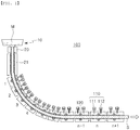
- FIG. 1 is a view illustrating a state of a continuous casting apparatus according to an embodiment of the present disclosure.
- molten steel obtained from a refining process may be injected into a tundish 10 from a ladle (not illustrated), and the molten steel temporarily stored in the tundish 10 may be supplied to a mold 20.
- the molten steel may be subjected to a primary cooling operation in the mold 20, and may be then solidified through a secondary cooling operation in a strand line 21 under the mold, to continuously produce a cast piece (S), such as a billet, a bloom, a slab, or the like.
- the molten steel (M) discharged through the mold 20 may be subjected to a primary cooling operation in the mold 20, and may be conveyed through successive segment(s) (1 to n+1) provided in a continuous casting facility 100 in a state which a surface thereof is somewhat solidified, and may be also compressed.
- each segment 110 may include an upper roller and a lower roller, and may further include a cylinder providing pressure to the upper roller and the lower roller.
- each of the segments may have an input side cylinder 111 and an output side cylinder 112, which provide pressure to the upper roller and the lower roller, on an input side and an output side, respectively.
- the cast piece (S) may be reduced in a thickness direction using the rollers described above in the segment corresponding to a final point in a solidification operation of the cast piece (S), to improve internal quality of a central portion in a continuous casting process.
- a segment corresponding to an end point of a solidification operation of the cast piece may be roughly milled and cast under a pressure of about 20 mm, to smoothly coagulate the cast piece (S) and to enhance quality such as flatness of the cast piece.
- the segment (n) when a point of the segment (n) corresponds to the final point in the solidification operation of the cast piece (S), the segment (n) may be cast by roughly milling and casting the cast piece (S) under a pressure of about 20 mm.
- a roll separation force in the segment (n) may be set to be higher than a roll separation force in the segment (n-1).
- a continuous casting apparatus may prevent the cast piece (S) from collapsing, and the like, by controlling a roll separation force as the cast piece (S) proceeds, to roughly mill the cast piece stably.
- roll separation force may be moderately adjusted to minimize a difference in thickness between a front end portion and a rear end portion of the cast piece, to satisfy a reference value for tolerance to a rolling operation, required in the subsequent process.
- FIG. 2 is a view illustrating another state of a continuous casting apparatus according to an embodiment of the present disclosure.
- FIG. 2 may be an example in which the situation illustrated in FIG. 1 further proceeds, and an end portion (S end ) of the cast piece (S) is then derived.
- a continuous casting apparatus may adjust pressures of cylinders of segments to adjust rolling reduction of the segment, depending on a position of the end portion (S end ) of the cast piece (S).
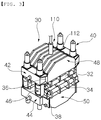
- FIG. 3 is a perspective view illustrating an example of a segment of the continuous casting apparatus illustrated in FIG. 1 .
- a segment 110 may include an upper roller 32 and a lower roller 34.
- the upper roller 32 and the lower roller 34 may be provided in forms of a plurality of rollers.
- Molten steel may be cast and rolled between the upper roller 32 and the lower roller 34 of the segment 110, to form a slab.
- Upper and lower frames 36 and 38 on which the upper roller 32 and the lower roller 34 are mounted may be provided with press-down cylinders 40, to pressure the upper roller 32 and the lower roller 34.
- four (4) cylinders present one (1) respectively on the left and the right, may be provided on input and output sides of the segment in total.
- the number of the cylinders is only illustrative, and may be set differently according to an embodiment.
- the cylinders 40 may be fixed by side boxes 42 and 44 on sides of the frame, and may be connected to tie rods 46.
- the upper roller 32 and the lower roller 34 may be assembled by girders 48 and 50 between the frames 36 and 38.
- FIG. 4 is a cutaway front view illustrating an example of the segment illustrated in FIG. 3 .
- a segment 400 may include upper and lower frames 436 and 438, an input side cylinder 440 and an output side cylinder 430 provided therebetween, and a driving roller 420 disposed between the input side cylinder 440 and the output side cylinder 430.
- the driving roller 420 may be provided to simply transport the cast piece, and may be different from the upper and lower rollers 432 and 434 for rolling the cast piece by the cylinders 430 and 440.
- Upper and lower portions of the cylinder 440 may be connected to each other by a tie rod 446, and the upper and lower rollers 432 and 434 may apply pressure to the cast piece in accordance with a pressure of the cylinder 440.
- a continuous casting apparatus may control a pressure of a segment in accordance with a position of an end portion of a cast piece, and will be described in more detail with reference to FIGS. 5 to 6 .
- FIG. 5 is a block diagram illustrating a configuration of a continuous casting apparatus according to an embodiment of the present disclosure.
- a continuous casting apparatus 200 may include a segment portion (not illustrated), an end position detector 210, and a controller 220.
- the segment portion may include a plurality of segments for casting a cast piece, and each of the segments may include an input side cylinder and an output side cylinder, as described above.
- the end position detector 210 may detect a position of an end portion of the cast piece (S end , illustrated in FIG. 2 ) .
- the end position detector 210 may apply various techniques for detecting an end portion of a cast piece. For example, the end portion of the cast piece may be detected by using an image detector, or the end portion of the cast piece may be detected by using a heat detector. In addition, various means may be applied in the present disclosure, and the end position detector 210 is not limited to any specific means in the present disclosure.
- the controller 220 may control a cylinder of a segment.
- the controller 220 may adjust pressures of cylinders included in the plurality of segments to adjust rolling reduction of the cast piece, in accordance with a position of an end portion of the cast piece.
- the controller 220 may set a roll gap difference between an input side cylinder and an output side cylinder of an N th segment as a first roll gap difference, when the end portion of the cast piece is not detected, for example, when the cast piece continues to be drawn from the mold. Meanwhile, the controller 220 may set a roll gap difference between the input side cylinder and the output side cylinder of the N th segment as a second roll gap difference smaller than the first roll gap difference, when the end portion of the cast piece is detected, for example, when the cast piece is not drawn from the mold.
- the second roll gap difference may change in accordance with a distance between an end portion of the cast piece and the N th segment. In one example, the second roll gap difference may change in proportion to a distance between the end portion of the cast piece and the N th segment.
- the controller 220 may control to roughly mill the N th segment corresponding to a final point in a solidification operation of the cast piece (S) by a relatively strong pressure, when the cast piece continues to be drawn from the mold, and may control to gradually decrease a pressure of the N th segment in accordance with a position of the end portion of the cast piece, when the cast piece is not drawn from the mold and the end portion of the cast piece is generated.
- the controller 220 may lower the roll gap difference between the input side cylinder and the output side cylinder of the N th segment on the basis of a predetermined rolling reduction amount, when the end portion of the cast piece proceeds beyond a reference distance.
- the controller 220 may periodically monitor a distance that the end portion of the cast piece moves, and when the end portion of the cast piece moves by the reference distance (Li), the roll gap control of the N th segment may be performed by calculating a target roll gap setting value (rolling reduction (PV) - ⁇ Ri), which reduces rolling reduction in the N th segment to be roughly milled by a specific rolling reduction ( ⁇ Ri).
- PV rolling reduction
- ⁇ Ri specific rolling reduction
- the controller 220 may adjust rolling reduction of an input side cylinder of an (N+1) th segment, on the basis of an amount of change of rolling reduction of the output side cylinder of the N th segment.
- the controller 220 may be implemented as a controller such as a programmable logic controller (PLC), but is not limited thereto.
- PLC programmable logic controller
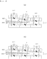
- FIGS. 6A and 6B are views illustrating segments to be controlled differently in accordance with a position of an end portion of a cast piece in a continuous casting apparatus according to an embodiment of the present disclosure.
- FIG. 6A illustrates an example in which an end portion of a cast piece has not yet been formed
- FIG. 6B illustrates an example in which an end portion of a cast piece has been formed and rolling reduction thereof is adjusted accordingly.
- molten steel 610 inside of a cast piece is roughly milled in a segment (n) corresponding to a non-solidified portion in which the molten steel 610 is less solidified. Therefore, a difference in heights of cast pieces between a previous segment (n-1) and a post segment (n+1) may be set as d1. As a result, since a roll gap difference between an input side cylinder and an output side cylinder of the segment (n) may be set to be equal to or greater than a specific roll gap difference, such a difference in the rolling reduction may be formed.
- rolling reduction of a segment (n) is reduced to d2, as an end portion of a cast piece proceeds. Therefore, rolling reduction may be reduced by reducing a roll gap difference between an input side cylinder and an output side cylinder of the segment (n).
- a rolling reduction of the input side cylinder of the segment (n+1) may change on the basis of an amount of change of rolling reduction of the output side cylinder of the segment (n).
- FIGS. 7A and 7B are views comparing shapes of a cast piece to be controlled differently in accordance with a position of an end portion of a cast piece.
- FIG. 7A illustrates an example in which an end portion of a cast piece has not yet been formed
- FIG. 7B illustrates an example in which an end portion of a cast piece has been formed and rolling reduction thereof is adjusted accordingly.
- FIG. 7A illustrates an example in which a cast piece is roughly milled by setting a roll gap difference between an input side cylinder and an output side cylinder of an N th segment as a first roll gap difference, when the cast piece is drawn from the mold.
- FIG. 7B illustrates an example in which a thickness of the cast piece is variably reduced by setting a roll gap difference between the input side cylinder and the output side cylinder of the N th segment as a second roll gap difference smaller than the first roll gap difference, when the cast piece is not drawn from the mold.
- the second roll gap difference may vary with a distance between the end portion of the cast piece and the N th segment.
- a section in which rolling reduction of the cast piece varies may also correspond to the distance (X1).
- a roll gap (Rt) may be formed only by the n th segment; and, in FIG. 7B , a roll gap formed by the n th segment may be only R1, and the rolling amount may be gradually decreased based on the moving distance of the end portion of the cast rolling reduction R2 may be set by the section (X1).
- FIG. 8 is a flowchart illustrating a continuous casting method according to an embodiment of the present disclosure.
- a continuous casting method illustrated in FIG. 8 may be performed in a continuous casting apparatus described with reference to FIGS. 1 to 7 , it can be easily understood with reference to the contents described with reference to FIGS. 1 to 7 .
- the continuous casting apparatus may roughly mill the cast piece by setting a roll gap difference between an input side cylinder and an output side cylinder of an N th segment as a first roll gap difference.
- the continuous casting apparatus may variably reduce a thickness of the cast piece by setting a roll gap difference between the input side cylinder and the output side cylinder of the N th segment as a second roll gap difference smaller than the first roll gap difference.
- the second roll gap difference may change in accordance with a distance between an end portion of the cast piece and the N th segment.
- the continuous casting apparatus may calculate a position of an end portion of the cast piece, and may track the position (S820).
- the continuous casting apparatus may perform the roughly milling under the same condition as the case in which the cast piece is drawn.
- the continuous casting apparatus may set a roll gap of cylinders of an (N-1) th segment as a roll gap of the input side cylinder of the N th segment.
- the continuous casting apparatus may set a roll gap of cylinders of an (N+1) th segment as a roll gap of the output side cylinder of the N th segment.
- the continuous casting apparatus may perform the variably reducing a thickness of the cast piece (S840 to S880).
- the continuous casting apparatus may calculate a current running distance of the end portion (S840).
- the rolling reduction may be reduced by a predetermined reduction amount, and may be re-adjusted (S860).
- the continuous casting apparatus may control the roll gap of the segment on the basis of this rolling reduction (S870).
- the continuous casting apparatus may stop the control of the rolling reduction, when the re-adjusted rolling reduction corresponds to the final rolling reduction (S880, YES).
- the above-described reduction operation of the rolling reduction (S840 to S880) may be repeatedly performed, when the re-adjusted rolling reduction does not correspond to the final rolling reduction (S880, NO).
Landscapes
- Engineering & Computer Science (AREA)
- Mechanical Engineering (AREA)
- Continuous Casting (AREA)
- Metal Rolling (AREA)
Abstract
According to one technical aspect of the present invention, a continuous casting method is performed in a continuous casting apparatus having a plurality of segments continuously provided, so as to continuously cast a slab drawn from a mold, and can comprise the steps of: rough milling the slab by setting a roll gap difference between an input side cylinder and an output side cylinder of an N-th segment as a first roll gap difference when the slab is drawn from the mold; and variably reducing the thickness of the slab by setting the roll gap difference between the input side cylinder and the output side cylinder of the N-th segment as a second roll gap difference smaller than the first roll gap difference, when the slab is not drawn from the mold. The second roll gap difference can change according to a distance between the end of the slab and the N-th segment.
Description
- The present disclosure relates to a continuous casting apparatus and a continuous casting method.
- Continuous casting technology is being developed as a steel manufacturing technique. Such continuous casting technology has advantages of being capable of performing a continuous casting process with a relatively large cross-section, and producing a cast piece several times larger than a conventional casting apparatus.
- Meanwhile, since a cast piece in a continuous casting technology has a relatively large size and a relatively long distance, weight of the cast piece may be relatively heavy to tens of tons. Therefore, influence of the weight and the temperature of the cast piece may affect the manufacturing environment of the cast piece, and such influences may cause an error in the production of the cast piece.
- Such prior art may be easily understood with reference to Korean Patent Publication No.
2015-0073760 2015-0073397 - (Patent Document 1) Korean Patent Publication No.
2015-0073760 - (Patent Document 2) Korean Patent Publication No.
2015-0073397 - The present disclosure has been made to solve the problems of the prior art described above. One technical aspect of the present disclosure is to provide a continuous casting apparatus comprising reducing rolling reduction of a roll gap, as a cast piece is drawn and an end portion of the cast piece progresses, which may prevent the occurrence of damage, such as collapse of the cast piece, or the like, even when the cast piece is roughly milled, and may also reduce a difference in thickness of the cast piece to be suitable for tolerance to a rolling operation, and a control method thereof.
- A technical aspect of the present disclosure proposes a continuous casting method. The continuous casting method may include roughly milling the cast piece by setting a roll gap difference between an input side cylinder and an output side cylinder of an Nth segment as a first roll gap difference, when the cast piece is drawn from the mold; and variably reducing a thickness of the cast piece by setting a roll gap difference between the input side cylinder and the output side cylinder of the Nth segment as a second roll gap difference smaller than the first roll gap difference, when the cast piece is not drawn from the mold. In this case, the second roll gap difference may change in accordance with a distance between an end portion of the cast piece and the Nth segment.
- In an embodiment, the second roll gap difference may change in proportion to a distance between the end portion of the cast piece and the Nth segment.
- In an embodiment, the roughly milling the cast piece may include setting a roll gap of cylinders of an (N-1)th segment as a roll gap of the input side cylinder of the Nth segment.
- In an embodiment, the roughly milling the cast piece may include setting a roll gap of cylinders of an (N+1)th segment as a roll gap of the output side cylinder of the Nth segment.
- In an embodiment, the variably reducing the cast piece may include confirming a position of the end portion of the cast piece; and lowering the roll gap difference between the input side cylinder and the output side cylinder of the Nth segment on the basis of a predetermined rolling reduction amount, when the end portion of the cast piece proceeds beyond a reference distance.
- In an embodiment, the variably reducing the cast piece may further include adjusting rolling reduction of an input side cylinder of an (N+1)th segment, on the basis of an amount of change of rolling reduction of the output side cylinder of the Nth segment.
- A technical aspect of the present disclosure proposes a continuous casting apparatus. The continuous casting apparatus may include a segment portion casting a cast piece, and including a plurality of segments including an input side cylinder and an output side cylinder; an end position detector detecting a position of an end portion of the cast piece; and a controller controlling pressures of cylinders included in the plurality of segments to adjust rolling reduction of the cast piece, in accordance with the position of the end portion of the cast piece. In this case, the controller may set a roll gap difference between an input side cylinder and an output side cylinder of an Nth segment as a first roll gap difference, when the end portion of the cast piece is not detected, and may set a roll gap difference between the input side cylinder and the output side cylinder of the Nth segment as a second roll gap difference smaller than the first roll gap difference, when the end portion of the cast piece is detected.
- In an embodiment, the controller may lower the roll gap difference between the input side cylinder and the output side cylinder of the Nth segment on the basis of a predetermined rolling reduction amount, when the end portion of the cast piece proceeds beyond a reference distance.
- In an embodiment, the controller may adjust rolling reduction of an input side cylinder of an (N+1)th segment, on the basis of an amount of change of rolling reduction of the output side cylinder of the Nth segment.
- The means for solving the above-mentioned problems does not list all the features of the present disclosure. Various means for solving the problems of the present disclosure can be understood in detail with reference to specific embodiments of the following detailed description.
- According to an aspect of the present disclosure, occurrence of damage, such as collapse of the cast piece, or the like may be prevented, even when the cast piece is roughly milled, by reducing rolling reduction of a roll gap, as a cast piece is drawn and an end portion of the cast piece progresses.
- According to an aspect of the present disclosure, a difference in thickness of the cast piece to be suitable for tolerance to a rolling operation may be reduced, by reducing rolling reduction of a roll gap, as a cast piece is drawn and an end portion of the cast piece progresses.
-
-
FIG. 1 is a view illustrating a state of a continuous casting apparatus according to an embodiment of the present disclosure. -
FIG. 2 is a view illustrating another state of a continuous casting apparatus according to an embodiment of the present disclosure. -
FIG. 3 is a perspective view illustrating an example of a segment of the continuous casting apparatus illustrated inFIG. 1 . -
FIG. 4 is a cutaway front view illustrating an example of the segment illustrated inFIG. 3 . -
FIG. 5 is a block diagram illustrating a configuration of a continuous casting apparatus according to an embodiment of the present disclosure. -
FIGS. 6A and 6B are views illustrating segments to be controlled differently in accordance with a position of an end portion of a cast piece in a continuous casting apparatus according to an embodiment of the present disclosure. -
FIGS. 7A and 7B are views comparing shapes of a cast piece to be controlled differently in accordance with a position of an end portion of a cast piece. -
FIG. 8 is a flowchart illustrating a continuous casting method according to an embodiment of the present disclosure. - Hereinafter, preferred embodiments of the present disclosure will be described with reference to the accompanying drawings.
- However, the embodiments of the present disclosure can be modified into various other forms, and the scope of the present disclosure may be not limited to the embodiments described below. Further, the embodiments of the present disclosure may be provided to more fully explain the present disclosure to those skilled in the art. It should be understood that the various embodiments of the present disclosure may be different, but need not be mutually exclusive.
- Also, "comprising" or "including" an element refers to that it may include other elements, rather than excluding other elements, unless specifically stated otherwise.
-
FIG. 1 is a view illustrating a state of a continuous casting apparatus according to an embodiment of the present disclosure. - The continuous casting will be described with reference to an example illustrated in
FIG. 1 . Molten steel obtained from a refining process may be injected into a tundish 10 from a ladle (not illustrated), and the molten steel temporarily stored in the tundish 10 may be supplied to amold 20. - The molten steel may be subjected to a primary cooling operation in the
mold 20, and may be then solidified through a secondary cooling operation in astrand line 21 under the mold, to continuously produce a cast piece (S), such as a billet, a bloom, a slab, or the like. - The molten steel (M) discharged through the
mold 20 may be subjected to a primary cooling operation in themold 20, and may be conveyed through successive segment(s) (1 to n+1) provided in acontinuous casting facility 100 in a state which a surface thereof is somewhat solidified, and may be also compressed. - For example, each
segment 110 may include an upper roller and a lower roller, and may further include a cylinder providing pressure to the upper roller and the lower roller. As illustrated in an example, each of the segments may have aninput side cylinder 111 and anoutput side cylinder 112, which provide pressure to the upper roller and the lower roller, on an input side and an output side, respectively. - The cast piece (S) may be reduced in a thickness direction using the rollers described above in the segment corresponding to a final point in a solidification operation of the cast piece (S), to improve internal quality of a central portion in a continuous casting process. For example, a segment corresponding to an end point of a solidification operation of the cast piece may be roughly milled and cast under a pressure of about 20 mm, to smoothly coagulate the cast piece (S) and to enhance quality such as flatness of the cast piece.
- For example, when a point of the segment (n) corresponds to the final point in the solidification operation of the cast piece (S), the segment (n) may be cast by roughly milling and casting the cast piece (S) under a pressure of about 20 mm. In this case, a roll separation force in the segment (n) may be set to be higher than a roll separation force in the segment (n-1).
- When a non-coagulated portion of the cast piece (S) is roughly milled to have a roll gap of 20 mm or more, the non-coagulated portion of the cast piece (S) may be collapsed. Therefore, it is important to prevent the non-coagulated portion of the cast piece (S) from collapsing.
- Therefore, a continuous casting apparatus according to the present disclosure may prevent the cast piece (S) from collapsing, and the like, by controlling a roll separation force as the cast piece (S) proceeds, to roughly mill the cast piece stably. In addition, roll separation force may be moderately adjusted to minimize a difference in thickness between a front end portion and a rear end portion of the cast piece, to satisfy a reference value for tolerance to a rolling operation, required in the subsequent process.
-
FIG. 2 is a view illustrating another state of a continuous casting apparatus according to an embodiment of the present disclosure.FIG. 2 may be an example in which the situation illustrated inFIG. 1 further proceeds, and an end portion (Send) of the cast piece (S) is then derived. - When the end portion (Send) of the cast piece (S) is derived in this way, for example, when the cast piece is not drawn from the mold, such as, when a pressure in the segment (n) is roughly milled under a relatively high pressure continuously, the problems such as collapse of the end portion (Send) of the cast piece (S) may occur.
- Therefore, a continuous casting apparatus according to an embodiment of the present disclosure may adjust pressures of cylinders of segments to adjust rolling reduction of the segment, depending on a position of the end portion (Send) of the cast piece (S).
-
FIG. 3 is a perspective view illustrating an example of a segment of the continuous casting apparatus illustrated inFIG. 1 . - Referring to
FIG. 3 , asegment 110 may include anupper roller 32 and alower roller 34. Theupper roller 32 and thelower roller 34 may be provided in forms of a plurality of rollers. - Molten steel may be cast and rolled between the
upper roller 32 and thelower roller 34 of thesegment 110, to form a slab. - Upper and
lower frames upper roller 32 and thelower roller 34 are mounted may be provided with press-downcylinders 40, to pressure theupper roller 32 and thelower roller 34. - In the illustrated example, four (4) cylinders, present one (1) respectively on the left and the right, may be provided on input and output sides of the segment in total. However, the number of the cylinders is only illustrative, and may be set differently according to an embodiment.
- The
cylinders 40 may be fixed byside boxes rods 46. - The
upper roller 32 and thelower roller 34 may be assembled bygirders frames -
FIG. 4 is a cutaway front view illustrating an example of the segment illustrated inFIG. 3 . - Referring to
FIG. 4 , asegment 400 may include upper andlower frames input side cylinder 440 and anoutput side cylinder 430 provided therebetween, and a drivingroller 420 disposed between theinput side cylinder 440 and theoutput side cylinder 430. - The driving
roller 420 may be provided to simply transport the cast piece, and may be different from the upper andlower rollers cylinders cylinder 440 may be connected to each other by atie rod 446, and the upper andlower rollers cylinder 440. - As described above, a continuous casting apparatus according to an embodiment of the present disclosure may control a pressure of a segment in accordance with a position of an end portion of a cast piece, and will be described in more detail with reference to
FIGS. 5 to 6 . -
FIG. 5 is a block diagram illustrating a configuration of a continuous casting apparatus according to an embodiment of the present disclosure. - Referring to
FIG. 5 , acontinuous casting apparatus 200 may include a segment portion (not illustrated), anend position detector 210, and acontroller 220. - The segment portion may include a plurality of segments for casting a cast piece, and each of the segments may include an input side cylinder and an output side cylinder, as described above.
- The
end position detector 210 may detect a position of an end portion of the cast piece (Send, illustrated inFIG. 2 ) . - The
end position detector 210 may apply various techniques for detecting an end portion of a cast piece. For example, the end portion of the cast piece may be detected by using an image detector, or the end portion of the cast piece may be detected by using a heat detector. In addition, various means may be applied in the present disclosure, and theend position detector 210 is not limited to any specific means in the present disclosure. - The
controller 220 may control a cylinder of a segment. - The
controller 220 may adjust pressures of cylinders included in the plurality of segments to adjust rolling reduction of the cast piece, in accordance with a position of an end portion of the cast piece. - For example, the
controller 220 may set a roll gap difference between an input side cylinder and an output side cylinder of an Nth segment as a first roll gap difference, when the end portion of the cast piece is not detected, for example, when the cast piece continues to be drawn from the mold. Meanwhile, thecontroller 220 may set a roll gap difference between the input side cylinder and the output side cylinder of the Nth segment as a second roll gap difference smaller than the first roll gap difference, when the end portion of the cast piece is detected, for example, when the cast piece is not drawn from the mold. - In this case, the second roll gap difference may change in accordance with a distance between an end portion of the cast piece and the Nth segment. In one example, the second roll gap difference may change in proportion to a distance between the end portion of the cast piece and the Nth segment.
- For example, the
controller 220 may control to roughly mill the Nth segment corresponding to a final point in a solidification operation of the cast piece (S) by a relatively strong pressure, when the cast piece continues to be drawn from the mold, and may control to gradually decrease a pressure of the Nth segment in accordance with a position of the end portion of the cast piece, when the cast piece is not drawn from the mold and the end portion of the cast piece is generated. - The
controller 220 may lower the roll gap difference between the input side cylinder and the output side cylinder of the Nth segment on the basis of a predetermined rolling reduction amount, when the end portion of the cast piece proceeds beyond a reference distance. - For example, the
controller 220 may periodically monitor a distance that the end portion of the cast piece moves, and when the end portion of the cast piece moves by the reference distance (Li), the roll gap control of the Nth segment may be performed by calculating a target roll gap setting value (rolling reduction (PV) - ΔRi), which reduces rolling reduction in the Nth segment to be roughly milled by a specific rolling reduction (ΔRi). - In one embodiment, the
controller 220 may adjust rolling reduction of an input side cylinder of an (N+1)th segment, on the basis of an amount of change of rolling reduction of the output side cylinder of the Nth segment. - The
controller 220 may be implemented as a controller such as a programmable logic controller (PLC), but is not limited thereto. -
FIGS. 6A and 6B are views illustrating segments to be controlled differently in accordance with a position of an end portion of a cast piece in a continuous casting apparatus according to an embodiment of the present disclosure. -
FIG. 6A illustrates an example in which an end portion of a cast piece has not yet been formed, andFIG. 6B illustrates an example in which an end portion of a cast piece has been formed and rolling reduction thereof is adjusted accordingly. - First, in the case of
FIG. 6A , it can be seen thatmolten steel 610 inside of a cast piece is roughly milled in a segment (n) corresponding to a non-solidified portion in which themolten steel 610 is less solidified. Therefore, a difference in heights of cast pieces between a previous segment (n-1) and a post segment (n+1) may be set as d1. As a result, since a roll gap difference between an input side cylinder and an output side cylinder of the segment (n) may be set to be equal to or greater than a specific roll gap difference, such a difference in the rolling reduction may be formed. - Next, in the case of
FIG. 6B , it can be seen that rolling reduction of a segment (n) is reduced to d2, as an end portion of a cast piece proceeds. Therefore, rolling reduction may be reduced by reducing a roll gap difference between an input side cylinder and an output side cylinder of the segment (n). - A rolling reduction of the input side cylinder of the segment (n+1) may change on the basis of an amount of change of rolling reduction of the output side cylinder of the segment (n).
-
FIGS. 7A and 7B are views comparing shapes of a cast piece to be controlled differently in accordance with a position of an end portion of a cast piece. -
FIG. 7A illustrates an example in which an end portion of a cast piece has not yet been formed, andFIG. 7B illustrates an example in which an end portion of a cast piece has been formed and rolling reduction thereof is adjusted accordingly. -
FIG. 7A illustrates an example in which a cast piece is roughly milled by setting a roll gap difference between an input side cylinder and an output side cylinder of an Nth segment as a first roll gap difference, when the cast piece is drawn from the mold. -
FIG. 7B illustrates an example in which a thickness of the cast piece is variably reduced by setting a roll gap difference between the input side cylinder and the output side cylinder of the Nth segment as a second roll gap difference smaller than the first roll gap difference, when the cast piece is not drawn from the mold. As illustrated, the second roll gap difference may vary with a distance between the end portion of the cast piece and the Nth segment. - As the end portion of the cast piece moves by a distance (X1), a section in which rolling reduction of the cast piece varies may also correspond to the distance (X1).
- For example, it can be seen that, in
FIG. 7A , a roll gap (Rt) may be formed only by the nth segment; and, inFIG. 7B , a roll gap formed by the nth segment may be only R1, and the rolling amount may be gradually decreased based on the moving distance of the end portion of the cast rolling reduction R2 may be set by the section (X1). - As a result, as the end portion of the cast piece passes a specific point, rolling reduction of the nth segment may gradually decrease on the basis of movement of the end portion of the cast piece. Therefore, tolerance to a rolling operation may be satisfied, since the end portion of the cast piece may be prevented from collapsing, and the amount of change of the cast piece may be set within a specific amount.
-
FIG. 8 is a flowchart illustrating a continuous casting method according to an embodiment of the present disclosure. - Since a continuous casting method illustrated in
FIG. 8 may be performed in a continuous casting apparatus described with reference toFIGS. 1 to 7 , it can be easily understood with reference to the contents described with reference toFIGS. 1 to 7 . - In a case in which a cast piece is drawn from a mold (S810, NO), the continuous casting apparatus may roughly mill the cast piece by setting a roll gap difference between an input side cylinder and an output side cylinder of an Nth segment as a first roll gap difference.
- In a case in which a casting operation in a mold is completed and a cast piece is drawn from the mold (S810, YES), the continuous casting apparatus may variably reduce a thickness of the cast piece by setting a roll gap difference between the input side cylinder and the output side cylinder of the Nth segment as a second roll gap difference smaller than the first roll gap difference. In this case, the second roll gap difference may change in accordance with a distance between an end portion of the cast piece and the Nth segment.
- For example, the continuous casting apparatus may calculate a position of an end portion of the cast piece, and may track the position (S820).
- When the position of the end portion of the cast piece is not equal to a predetermined position (PI), the continuous casting apparatus may perform the roughly milling under the same condition as the case in which the cast piece is drawn.
- In one example, the continuous casting apparatus may set a roll gap of cylinders of an (N-1)th segment as a roll gap of the input side cylinder of the Nth segment. Alternatively, the continuous casting apparatus may set a roll gap of cylinders of an (N+1)th segment as a roll gap of the output side cylinder of the Nth segment.
- When the position of the end portion of the cast piece is equal to a predetermined position (PI), the continuous casting apparatus may perform the variably reducing a thickness of the cast piece (S840 to S880).
- For example, the continuous casting apparatus may calculate a current running distance of the end portion (S840). When the current running distance corresponds to the reference distance (S850), the rolling reduction may be reduced by a predetermined reduction amount, and may be re-adjusted (S860). Further, the continuous casting apparatus may control the roll gap of the segment on the basis of this rolling reduction (S870).
- The continuous casting apparatus may stop the control of the rolling reduction, when the re-adjusted rolling reduction corresponds to the final rolling reduction (S880, YES). The above-described reduction operation of the rolling reduction (S840 to S880) may be repeatedly performed, when the re-adjusted rolling reduction does not correspond to the final rolling reduction (S880, NO).
- While the present disclosure has been particularly illustrated and described with reference to example embodiments thereof, it can be understood that the present disclosure is not limited to the disclosed example embodiments, but, on the contrary, Those skilled in the art will appreciate that various modifications, additions, and substitutions may be possible, without departing from the scope and spirit of the present disclosure as disclosed in the accompanying claims.
- Therefore, the spirit of the present disclosure should not be construed as being limited to the above-described embodiments, and all of the equivalents or equivalents of the claims, as well as the following claims.
Claims (9)
- A continuous casting method, performed in a continuous casting apparatus having a plurality of segments continuously provided, to continuously cast a cast piece drawn from a mold, comprising:roughly milling the cast piece by setting a roll gap difference between an input side cylinder and an output side cylinder of an Nth segment as a first roll gap difference, when the cast piece is drawn from the mold; andvariably reducing a thickness of the cast piece by setting a roll gap difference between the input side cylinder and the output side cylinder of the Nth segment as a second roll gap difference smaller than the first roll gap difference, when the cast piece is not drawn from the mold,wherein the second roll gap difference changes in accordance with a distance between an end portion of the cast piece and the Nth segment.
- The continuous casting method according to claim 1, wherein the second roll gap difference changes in proportion to a distance between the end portion of the cast piece and the Nth segment.
- The continuous casting method according to claim 1, wherein the roughly milling the cast piece comprises setting a roll gap of cylinders of an (N-1)th segment as a roll gap of the input side cylinder of the Nth segment.
- The continuous casting method according to claim 1, wherein the roughly milling the cast piece comprises setting a roll gap of cylinders of an (N+1)th segment as a roll gap of the output side cylinder of the Nth segment.
- The continuous casting method according to claim 1, wherein the variably reducing the cast piece comprises:confirming a position of the end portion of the cast piece; andlowering the roll gap difference between the input side cylinder and the output side cylinder of the Nth segment on the basis of a predetermined rolling reduction amount, when the end portion of the cast piece proceeds beyond a reference distance.
- The continuous casting method according to claim 5, wherein the variably reducing the cast piece further comprises adjusting rolling reduction of an input side cylinder of an (N+1)th segment, on the basis of an amount of change of rolling reduction of the output side cylinder of the Nth segment.
- A continuous casting apparatus comprising:a segment portion casting a cast piece, and including a plurality of segments including an input side cylinder and an output side cylinder;an end position detector detecting a position of an end portion of the cast piece; anda controller controlling pressures of cylinders included in the plurality of segments to adjust rolling reduction of the cast piece, in accordance with the position of the end portion of the cast piece,wherein the controller sets a roll gap difference between an input side cylinder and an output side cylinder of an Nth segment as a first roll gap difference, when the end portion of the cast piece is not detected, and sets a roll gap difference between the input side cylinder and the output side cylinder of the Nth segment as a second roll gap difference smaller than the first roll gap difference, when the end portion of the cast piece is detected.
- The continuous casting apparatus according to claim 7, wherein the controller lowers the roll gap difference between the input side cylinder and the output side cylinder of the Nth segment on the basis of a predetermined rolling reduction amount, when the end portion of the cast piece proceeds beyond a reference distance.
- The continuous casting apparatus according to claim 8, wherein the controller adjusts rolling reduction of an input side cylinder of an (N+1)th segment, on the basis of an amount of change of rolling reduction of the output side cylinder of the Nth segment.
Applications Claiming Priority (2)
| Application Number | Priority Date | Filing Date | Title |
|---|---|---|---|
| KR1020160176895A KR101858859B1 (en) | 2016-12-22 | 2016-12-22 | Continuous casting equipment and control method thereof |
| PCT/KR2017/015266 WO2018117698A1 (en) | 2016-12-22 | 2017-12-21 | Continuous casting apparatus and method |
Publications (2)
| Publication Number | Publication Date |
|---|---|
| EP3560629A4 EP3560629A4 (en) | 2019-10-30 |
| EP3560629A1 true EP3560629A1 (en) | 2019-10-30 |
Family
ID=62485909
Family Applications (1)
| Application Number | Title | Priority Date | Filing Date |
|---|---|---|---|
| EP17884536.8A Withdrawn EP3560629A1 (en) | 2016-12-22 | 2017-12-21 | Continuous casting apparatus and method |
Country Status (5)
| Country | Link |
|---|---|
| EP (1) | EP3560629A1 (en) |
| JP (1) | JP2020501913A (en) |
| KR (1) | KR101858859B1 (en) |
| CN (1) | CN110114171A (en) |
| WO (1) | WO2018117698A1 (en) |
Cited By (1)
| Publication number | Priority date | Publication date | Assignee | Title |
|---|---|---|---|---|
| IT202200006581A1 (en) * | 2022-04-04 | 2023-10-04 | Danieli Off Mecc | SEGMENT OF A SOFT REDUCTION DEVICE TO PERFORM A SOFT REDUCTION OF SLAB |
Family Cites Families (11)
| Publication number | Priority date | Publication date | Assignee | Title |
|---|---|---|---|---|
| JPH0692022B2 (en) * | 1990-05-30 | 1994-11-16 | 新日本製鐵株式会社 | Light reduction method for continuous cast slab |
| JP3452799B2 (en) * | 1998-06-24 | 2003-09-29 | 住友金属工業株式会社 | Continuous casting guide roll device and continuous casting method |
| JP2000334552A (en) * | 1999-05-25 | 2000-12-05 | Sumitomo Metal Ind Ltd | Continuous casting of thin slabs |
| DE19933635A1 (en) * | 1999-07-17 | 2001-01-18 | Sms Demag Ag | Method and device for changing the format thickness of the cast strand of a continuous caster in a continuous casting operation |
| JP2003290893A (en) | 2002-03-28 | 2003-10-14 | Sumitomo Heavy Ind Ltd | Adjusting method for light reduction zone in continuous casting facility and adjusting mechanism for light reduction zone |
| KR100529061B1 (en) * | 2003-12-23 | 2005-11-15 | 재단법인 포항산업과학연구원 | Position sensor calibration method of segment clamping cylinder |
| JP5472857B2 (en) | 2010-04-23 | 2014-04-16 | 新日鉄住金エンジニアリング株式会社 | Guide roll segment of continuous casting equipment |
| KR20150073760A (en) | 2013-12-23 | 2015-07-01 | 주식회사 포스코 | Segment for continuous casting with preventing surface defects and adjusting the roll gap function |
| KR20150073397A (en) | 2013-12-23 | 2015-07-01 | 주식회사 포스코 | Apparatus for high speed continuous casting |
| KR101647207B1 (en) * | 2014-11-27 | 2016-08-10 | 주식회사 포스코 | Method and apparatus for continuous casting |
| JP2016179485A (en) * | 2015-03-24 | 2016-10-13 | 株式会社神戸製鋼所 | Continuous casting method |
-
2016
- 2016-12-22 KR KR1020160176895A patent/KR101858859B1/en active Active
-
2017
- 2017-12-21 WO PCT/KR2017/015266 patent/WO2018117698A1/en not_active Ceased
- 2017-12-21 CN CN201780079301.XA patent/CN110114171A/en not_active Withdrawn
- 2017-12-21 EP EP17884536.8A patent/EP3560629A1/en not_active Withdrawn
- 2017-12-21 JP JP2019533563A patent/JP2020501913A/en active Pending
Cited By (2)
| Publication number | Priority date | Publication date | Assignee | Title |
|---|---|---|---|---|
| IT202200006581A1 (en) * | 2022-04-04 | 2023-10-04 | Danieli Off Mecc | SEGMENT OF A SOFT REDUCTION DEVICE TO PERFORM A SOFT REDUCTION OF SLAB |
| WO2023194868A1 (en) * | 2022-04-04 | 2023-10-12 | Danieli & C. Officine Meccaniche S.P.A. | Segment of a soft reduction device for carrying out a soft reduction of slabs |
Also Published As
| Publication number | Publication date |
|---|---|
| EP3560629A4 (en) | 2019-10-30 |
| CN110114171A (en) | 2019-08-09 |
| WO2018117698A1 (en) | 2018-06-28 |
| KR101858859B1 (en) | 2018-05-17 |
| JP2020501913A (en) | 2020-01-23 |
Similar Documents
| Publication | Publication Date | Title |
|---|---|---|
| US10464111B2 (en) | Method of forming tailored cast blanks | |
| KR102079220B1 (en) | Steel plant with multiple co-rolling line and corresponding method of production | |
| RU2461442C1 (en) | Device and method for metal casting and rolling | |
| JP2012011459A (en) | Soft reduction method of cast slab in continuous casting | |
| US11433442B2 (en) | Continuous casting and rolling plant for the production of metallurgical products | |
| US9776229B2 (en) | Method for influencing the geometry of a rolled item in a controlled manner | |
| JP5779978B2 (en) | Light reduction method of slab in continuous casting | |
| CN109848383B (en) | A flexible reduction method for improving the internal quality of the slab | |
| CN104837574B (en) | Influence on the width of the rolled strip | |
| CN107088650A (en) | A kind of control method for improving continuous casting machine roll-gap precision | |
| KR101858859B1 (en) | Continuous casting equipment and control method thereof | |
| CN103817299B (en) | Continuously cast bloom shape control method and crystallizer | |
| TWI615216B (en) | Steel continuous casting method | |
| CN104889354A (en) | Method for controlling torque of withdrawing and straightening machines for improving screw-down effects for solidification tail ends of continuous casting slabs | |
| US7025118B2 (en) | Method and device for continuously casting ingots, slabs or thin slabs | |
| JP5810651B2 (en) | Billet continuous casting method | |
| CN116475229A (en) | Endless rolling finishing method for hot-rolled strip steel | |
| JP2009519134A (en) | Method and apparatus for continuous casting of thin strips | |
| CN107008877A (en) | A kind of control method for improving continuous casting machine roll-gap precision | |
| KR101316756B1 (en) | Control method for Centerline Segregation by measuring slab form | |
| RU2226138C2 (en) | Billet continuous casting process | |
| JP6435977B2 (en) | How to change the slab width during continuous casting | |
| US8381794B2 (en) | Mold for the continuous casting of preliminary sections, in particular double T-shaped preliminary sections | |
| JPWO1997014522A1 (en) | Continuous casting method and apparatus | |
| WO2016121355A1 (en) | Continuous casting method for steel |
Legal Events
| Date | Code | Title | Description |
|---|---|---|---|
| PUAI | Public reference made under article 153(3) epc to a published international application that has entered the european phase |
Free format text: ORIGINAL CODE: 0009012 |
|
| 17P | Request for examination filed |
Effective date: 20190607 |
|
| A4 | Supplementary search report drawn up and despatched |
Effective date: 20190821 |
|
| AK | Designated contracting states |
Kind code of ref document: A1 Designated state(s): AL AT BE BG CH CY CZ DE DK EE ES FI FR GB GR HR HU IE IS IT LI LT LU LV MC MK MT NL NO PL PT RO RS SE SI SK SM TR |
|
| AX | Request for extension of the european patent |
Extension state: BA ME |
|
| STAA | Information on the status of an ep patent application or granted ep patent |
Free format text: STATUS: THE APPLICATION HAS BEEN WITHDRAWN |
|
| DAV | Request for validation of the european patent (deleted) | ||
| DAX | Request for extension of the european patent (deleted) | ||
| 18W | Application withdrawn |
Effective date: 20200309 |