EP3560605A1 - Methods and systems for collecting droplets of strain hardening viscoelastic fluids in a spray - Google Patents
Methods and systems for collecting droplets of strain hardening viscoelastic fluids in a spray Download PDFInfo
- Publication number
- EP3560605A1 EP3560605A1 EP19170434.5A EP19170434A EP3560605A1 EP 3560605 A1 EP3560605 A1 EP 3560605A1 EP 19170434 A EP19170434 A EP 19170434A EP 3560605 A1 EP3560605 A1 EP 3560605A1
- Authority
- EP
- European Patent Office
- Prior art keywords
- spray
- counter
- collection shell
- nip
- nozzle
- Prior art date
- Legal status (The legal status is an assumption and is not a legal conclusion. Google has not performed a legal analysis and makes no representation as to the accuracy of the status listed.)
- Granted
Links
Images






Classifications
-
- B—PERFORMING OPERATIONS; TRANSPORTING
- B05—SPRAYING OR ATOMISING IN GENERAL; APPLYING FLUENT MATERIALS TO SURFACES, IN GENERAL
- B05B—SPRAYING APPARATUS; ATOMISING APPARATUS; NOZZLES
- B05B17/00—Apparatus for spraying or atomising liquids or other fluent materials, not covered by the preceding groups
- B05B17/04—Apparatus for spraying or atomising liquids or other fluent materials, not covered by the preceding groups operating with special methods
-
- A—HUMAN NECESSITIES
- A61—MEDICAL OR VETERINARY SCIENCE; HYGIENE
- A61F—FILTERS IMPLANTABLE INTO BLOOD VESSELS; PROSTHESES; DEVICES PROVIDING PATENCY TO, OR PREVENTING COLLAPSING OF, TUBULAR STRUCTURES OF THE BODY, e.g. STENTS; ORTHOPAEDIC, NURSING OR CONTRACEPTIVE DEVICES; FOMENTATION; TREATMENT OR PROTECTION OF EYES OR EARS; BANDAGES, DRESSINGS OR ABSORBENT PADS; FIRST-AID KITS
- A61F9/00—Methods or devices for treatment of the eyes; Devices for putting in contact-lenses; Devices to correct squinting; Apparatus to guide the blind; Protective devices for the eyes, carried on the body or in the hand
- A61F9/0008—Introducing ophthalmic products into the ocular cavity or retaining products therein
-
- B—PERFORMING OPERATIONS; TRANSPORTING
- B01—PHYSICAL OR CHEMICAL PROCESSES OR APPARATUS IN GENERAL
- B01J—CHEMICAL OR PHYSICAL PROCESSES, e.g. CATALYSIS OR COLLOID CHEMISTRY; THEIR RELEVANT APPARATUS
- B01J2/00—Processes or devices for granulating materials, e.g. fertilisers in general; Rendering particulate materials free flowing in general, e.g. making them hydrophobic
- B01J2/02—Processes or devices for granulating materials, e.g. fertilisers in general; Rendering particulate materials free flowing in general, e.g. making them hydrophobic by dividing the liquid material into drops, e.g. by spraying, and solidifying the drops
- B01J2/04—Processes or devices for granulating materials, e.g. fertilisers in general; Rendering particulate materials free flowing in general, e.g. making them hydrophobic by dividing the liquid material into drops, e.g. by spraying, and solidifying the drops in a gaseous medium
-
- B—PERFORMING OPERATIONS; TRANSPORTING
- B05—SPRAYING OR ATOMISING IN GENERAL; APPLYING FLUENT MATERIALS TO SURFACES, IN GENERAL
- B05B—SPRAYING APPARATUS; ATOMISING APPARATUS; NOZZLES
- B05B12/00—Arrangements for controlling delivery; Arrangements for controlling the spray area
- B05B12/16—Arrangements for controlling delivery; Arrangements for controlling the spray area for controlling the spray area
- B05B12/20—Masking elements, i.e. elements defining uncoated areas on an object to be coated
- B05B12/26—Masking elements, i.e. elements defining uncoated areas on an object to be coated for masking cavities
-
- A—HUMAN NECESSITIES
- A61—MEDICAL OR VETERINARY SCIENCE; HYGIENE
- A61J—CONTAINERS SPECIALLY ADAPTED FOR MEDICAL OR PHARMACEUTICAL PURPOSES; DEVICES OR METHODS SPECIALLY ADAPTED FOR BRINGING PHARMACEUTICAL PRODUCTS INTO PARTICULAR PHYSICAL OR ADMINISTERING FORMS; DEVICES FOR ADMINISTERING FOOD OR MEDICINES ORALLY; BABY COMFORTERS; DEVICES FOR RECEIVING SPITTLE
- A61J3/00—Devices or methods specially adapted for bringing pharmaceutical products into particular physical or administering forms
- A61J3/005—Coating of tablets or the like
-
- A—HUMAN NECESSITIES
- A61—MEDICAL OR VETERINARY SCIENCE; HYGIENE
- A61M—DEVICES FOR INTRODUCING MEDIA INTO, OR ONTO, THE BODY; DEVICES FOR TRANSDUCING BODY MEDIA OR FOR TAKING MEDIA FROM THE BODY; DEVICES FOR PRODUCING OR ENDING SLEEP OR STUPOR
- A61M11/00—Sprayers or atomisers specially adapted for therapeutic purposes
-
- A—HUMAN NECESSITIES
- A61—MEDICAL OR VETERINARY SCIENCE; HYGIENE
- A61M—DEVICES FOR INTRODUCING MEDIA INTO, OR ONTO, THE BODY; DEVICES FOR TRANSDUCING BODY MEDIA OR FOR TAKING MEDIA FROM THE BODY; DEVICES FOR PRODUCING OR ENDING SLEEP OR STUPOR
- A61M35/00—Devices for applying media, e.g. remedies, on the human body
- A61M35/003—Portable hand-held applicators having means for dispensing or spreading integral media
-
- B—PERFORMING OPERATIONS; TRANSPORTING
- B05—SPRAYING OR ATOMISING IN GENERAL; APPLYING FLUENT MATERIALS TO SURFACES, IN GENERAL
- B05B—SPRAYING APPARATUS; ATOMISING APPARATUS; NOZZLES
- B05B12/00—Arrangements for controlling delivery; Arrangements for controlling the spray area
- B05B12/16—Arrangements for controlling delivery; Arrangements for controlling the spray area for controlling the spray area
- B05B12/18—Arrangements for controlling delivery; Arrangements for controlling the spray area for controlling the spray area using fluids, e.g. gas streams
-
- B—PERFORMING OPERATIONS; TRANSPORTING
- B05—SPRAYING OR ATOMISING IN GENERAL; APPLYING FLUENT MATERIALS TO SURFACES, IN GENERAL
- B05B—SPRAYING APPARATUS; ATOMISING APPARATUS; NOZZLES
- B05B12/00—Arrangements for controlling delivery; Arrangements for controlling the spray area
- B05B12/16—Arrangements for controlling delivery; Arrangements for controlling the spray area for controlling the spray area
- B05B12/32—Shielding elements, i.e. elements preventing overspray from reaching areas other than the object to be sprayed
-
- B—PERFORMING OPERATIONS; TRANSPORTING
- B05—SPRAYING OR ATOMISING IN GENERAL; APPLYING FLUENT MATERIALS TO SURFACES, IN GENERAL
- B05B—SPRAYING APPARATUS; ATOMISING APPARATUS; NOZZLES
- B05B3/00—Spraying or sprinkling apparatus with moving outlet elements or moving deflecting elements
- B05B3/02—Spraying or sprinkling apparatus with moving outlet elements or moving deflecting elements with rotating elements
-
- B—PERFORMING OPERATIONS; TRANSPORTING
- B05—SPRAYING OR ATOMISING IN GENERAL; APPLYING FLUENT MATERIALS TO SURFACES, IN GENERAL
- B05B—SPRAYING APPARATUS; ATOMISING APPARATUS; NOZZLES
- B05B3/00—Spraying or sprinkling apparatus with moving outlet elements or moving deflecting elements
- B05B3/02—Spraying or sprinkling apparatus with moving outlet elements or moving deflecting elements with rotating elements
- B05B3/025—Rotational joints
- B05B3/026—Rotational joints the fluid passing axially from one joint element to another
-
- B—PERFORMING OPERATIONS; TRANSPORTING
- B05—SPRAYING OR ATOMISING IN GENERAL; APPLYING FLUENT MATERIALS TO SURFACES, IN GENERAL
- B05B—SPRAYING APPARATUS; ATOMISING APPARATUS; NOZZLES
- B05B3/00—Spraying or sprinkling apparatus with moving outlet elements or moving deflecting elements
- B05B3/02—Spraying or sprinkling apparatus with moving outlet elements or moving deflecting elements with rotating elements
- B05B3/08—Spraying or sprinkling apparatus with moving outlet elements or moving deflecting elements with rotating elements in association with stationary outlet or deflecting elements
- B05B3/082—Spraying or sprinkling apparatus with moving outlet elements or moving deflecting elements with rotating elements in association with stationary outlet or deflecting elements the spraying being effected by centrifugal forces
-
- B—PERFORMING OPERATIONS; TRANSPORTING
- B05—SPRAYING OR ATOMISING IN GENERAL; APPLYING FLUENT MATERIALS TO SURFACES, IN GENERAL
- B05B—SPRAYING APPARATUS; ATOMISING APPARATUS; NOZZLES
- B05B3/00—Spraying or sprinkling apparatus with moving outlet elements or moving deflecting elements
- B05B3/02—Spraying or sprinkling apparatus with moving outlet elements or moving deflecting elements with rotating elements
- B05B3/10—Spraying or sprinkling apparatus with moving outlet elements or moving deflecting elements with rotating elements discharging over substantially the whole periphery of the rotating member
- B05B3/1035—Driving means; Parts thereof, e.g. turbine, shaft, bearings
-
- B—PERFORMING OPERATIONS; TRANSPORTING
- B05—SPRAYING OR ATOMISING IN GENERAL; APPLYING FLUENT MATERIALS TO SURFACES, IN GENERAL
- B05B—SPRAYING APPARATUS; ATOMISING APPARATUS; NOZZLES
- B05B7/00—Spraying apparatus for discharge of liquids or other fluent materials from two or more sources, e.g. of liquid and air, of powder and gas
- B05B7/0075—Nozzle arrangements in gas streams
-
- F—MECHANICAL ENGINEERING; LIGHTING; HEATING; WEAPONS; BLASTING
- F26—DRYING
- F26B—DRYING SOLID MATERIALS OR OBJECTS BY REMOVING LIQUID THEREFROM
- F26B3/00—Drying solid materials or objects by processes involving the application of heat
- F26B3/02—Drying solid materials or objects by processes involving the application of heat by convection, i.e. heat being conveyed from a heat source to the materials or objects to be dried by a gas or vapour, e.g. air
- F26B3/10—Drying solid materials or objects by processes involving the application of heat by convection, i.e. heat being conveyed from a heat source to the materials or objects to be dried by a gas or vapour, e.g. air the gas or vapour carrying the materials or objects to be dried with it
- F26B3/12—Drying solid materials or objects by processes involving the application of heat by convection, i.e. heat being conveyed from a heat source to the materials or objects to be dried by a gas or vapour, e.g. air the gas or vapour carrying the materials or objects to be dried with it in the form of a spray, i.e. sprayed or dispersed emulsions or suspensions
-
- B—PERFORMING OPERATIONS; TRANSPORTING
- B01—PHYSICAL OR CHEMICAL PROCESSES OR APPARATUS IN GENERAL
- B01J—CHEMICAL OR PHYSICAL PROCESSES, e.g. CATALYSIS OR COLLOID CHEMISTRY; THEIR RELEVANT APPARATUS
- B01J13/00—Colloid chemistry, e.g. the production of colloidal materials or their solutions, not otherwise provided for; Making microcapsules or microballoons
- B01J13/0095—Preparation of aerosols
-
- B—PERFORMING OPERATIONS; TRANSPORTING
- B05—SPRAYING OR ATOMISING IN GENERAL; APPLYING FLUENT MATERIALS TO SURFACES, IN GENERAL
- B05B—SPRAYING APPARATUS; ATOMISING APPARATUS; NOZZLES
- B05B12/00—Arrangements for controlling delivery; Arrangements for controlling the spray area
- B05B12/16—Arrangements for controlling delivery; Arrangements for controlling the spray area for controlling the spray area
- B05B12/20—Masking elements, i.e. elements defining uncoated areas on an object to be coated
-
- B—PERFORMING OPERATIONS; TRANSPORTING
- B05—SPRAYING OR ATOMISING IN GENERAL; APPLYING FLUENT MATERIALS TO SURFACES, IN GENERAL
- B05B—SPRAYING APPARATUS; ATOMISING APPARATUS; NOZZLES
- B05B9/00—Spraying apparatus for discharge of liquids or other fluent material, without essentially mixing with gas or vapour
- B05B9/03—Spraying apparatus for discharge of liquids or other fluent material, without essentially mixing with gas or vapour characterised by means for supplying liquid or other fluent material
Definitions
- the disclosed methods and systems generally relate to spray deposition systems and methods and more specifically to the controlled collection and direction of such spray in such systems.
- FIGURE 14 illustrates an example of such a system 1400 that includes a spray mechanism having two counter rotating rollers 1402 and 1404 that are in hard contact with each other.
- Such systems generally allow for the spraying of viscoelastic fluids both at room temperature (e.g., polymer solutions and complex formulations) and at elevated temperatures (e.g., polymer melts).
- rollers or small rollers Existing technologies can work with large rollers or small rollers.
- large rollers may be used for high throughput applications (e.g., as a unit operation at the end of a manufacturing line for producing droplets or powders)
- small rollers may be used for smaller output but at an equally small device footprint (e.g., as a handheld device for precision dispensing).
- the collection of the spray produced is generally integral to the spray technology.
- the spray droplets tend to naturally follow their own trajectory based on their initial velocity (e.g., upon filament break-up) and droplet size. These trajectory lines often follow a spray cone 1410. Depending on different parameters such as the roller diameter, roller speeds, contact force, and the fluid rheology, this spray cone 1410 is usually wide enough to make controlled deposition on a limited difficult.
- FIGURE 15 illustrates a system 1500 for obtaining controlled deposition on a limited area that includes the use of a mask 1504 (or, alternatively, a sheet with an orifice) to block the unwanted spray fraction of the spray cone 1510 from the spray source 1502, such as a pair of counter-rotating rollers. While this system 1500 may limit the delivery area to a limited space 1512 on a surface 1520, the system is also significantly inefficient in that most of the unwanted spray collects on the mask 1504 (or sheet).
- a mask 1504 or, alternatively, a sheet with an orifice
- This system 1500 is also wasteful, particularly for high value fluids that are only available in limited volumes (e.g., specialized drugs and bioactives manufactured in the ⁇ g scale).
- Embodiments of the disclosed technology are generally directed to systems and methods for the efficient collection of the spray produced in spray processing.
- Such embodiments may include a downscaled system, e.g., a system having 5-50mm rollers, and may include a collection shell leading to a nozzle having a suitable geometry and controlled air flow using air knives positioned and oriented to increase collection of the spray therethrough.
- Embodiments of the disclosed technology may advantageously enable the collection of a large portion, e.g., up to or over 85%, of the liquid that is input into the system.
- Prior systems have efficiencies less than 1% in larger roller systems (e.g., greater than 50mm roller diameter) and at 10% in smaller roller systems (e.g., less than 50mm roller diameter).
- Certain embodiments in accordance with the disclosed technology may further focus the spray into a defined and limited area, e.g., an area of the order of 1-2 cm 2 , which is comparable to the exposed surface area of the human eye.
- FIGURE 1 is a functional diagram illustrating an example of an aerosol producing system 100 in accordance with certain embodiments of the disclosed technology.
- the system 100 has a pair of counter-rotating rollers 102 and 104 that are in contact with each other, and a collection shell around the rollers 102 and 104 configured to collect the spray efficiently along its natural direction.
- the collection shell has a converging profile designed to guide the spray produced at the nip (e.g., the point of roller contact) into and through a nozzle 112 (e.g., exit port) that is integrated with the collection shell.
- the system 100 also includes a pair of air knives 114 and 116 that are configured to assist with the redirection of the spray into the nozzle 112.
- the air knives 114 and 116 are generally designed and placed strategically for collection of the spray at the nozzle 112.
- the air flow induced by the air knives 114 and 116 is generally tangential to the surface of the collection shell but may be at any suitable angle therefrom.
- FIGURE 2 illustrates a first example of an aerosol producing system 200 in accordance with certain embodiments of the disclosed technology.
- the system 200 has a pair of counter-rotating rollers 202 and 204 and a collection shell 210 around the rollers 202 and 204 configured to collect the spray efficiently along its natural direction.
- the collection shell 210 has a converging profile designed to guide the spray produced at the nip (e.g., the point of roller contact) into a nozzle 212 (e.g., exit port) that is integrated with the collection shell 210.
- the system 200 also includes a pair of air knives 214 and 216 that are configured to assist with the redirection of the spray into the nozzle 212.
- the term air knife generally refers to a device or component having a narrow opening through which air may be forced, e.g., by a certain type of fan or blower or other suitable device.
- the air knives 214 and 216 are generally designed and placed along the spray cone.
- the inlet pressure into the air knives 214 and 216 may be optimized for maximal collection of the spray at the nozzle 212 (e.g., measured as collected mass over exposure time).
- the air flow induced by the air knives 214 and 216 is generally tangential to the surface of the collection shell 210.
- Determination and maintenance of the amount air flow in the system is integral for guiding the spray and minimizing spray deposition in the shell surface near the nozzle.
- the air flow from the air knives 214 and 216 creates fast moving streamlines close to the surface of the collection shell 210 that prevent particles from impinging and collecting on the surface.
- the nozzle 212 may be modular and readily interchangeable with the rest of the system 200.
- the nozzle 212 may be positioned on the collection shell 210 and secured by any suitable securing mechanism.
- the geometry of the nozzle 212 can be modified depending on the intended deposition area, e.g., with respect to the nascent spray profile.
- the nozzle geometry may be selected to more closely match the exposed surface area of the eye. Such selection may also have a slight effect on the collection efficiency given the natural splay of the spray cone, for example.
- the design of the collection shell 210 and focusing of air flow by way of the air knives 214 and 216 may be based on the natural spray cone profile, for example.
- FIGURES 3-5 illustrate three different types of nozzle geometries that may be implemented.
- FIGURE 3 illustrates a nozzle 312 having an elliptical opening 314 that is perpendicular to the splay angle
- FIGURE 4 illustrates a nozzle 422 having an elliptical opening 424 that is parallel to the splay angle
- FIGURE 5 illustrates a nozzle 532 having a circular opening 534. It should be noted that the factor difference between the exit port geometries is generally small given the already large spray collection yield.
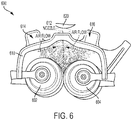
- FIGURE 6 illustrates a second example of an aerosol producing system 600 in accordance with certain embodiments of the disclosed technology. Similar to the system 200 illustrated by FIGURE 2 , the system 600 includes a pair of counter-rotating rollers 602 and 604, a collection shell 610 having a nozzle 612, and a pair of air knives 614 and 616 configured to direct the spray toward and through the nozzle 612. It should be noted that the collection shell 610 of FIGURE 6 has a different shape (e.g., curvature) than the collection shell 210 illustrated by FIGURE 2 .
- shape e.g., curvature
- optimal air flow for the collection shell 210 of FIGURE 2 may be approximately 20-30 standard cubic feet per hour whereas the optimal air flow for the collection shell 610 of FIGURE 6 is approximately 40-50 standard cubic feet per hour. At these air flows, the spray collection efficiency can increase to as high as 85% or even greater.
- FIGURE 7 illustrates a third example of an aerosol producing system 700 in accordance with certain embodiments of the disclosed technology.
- a collection shell 710 having a nozzle 712 is created, e.g., by way of three-dimensional (3D) printing, with a design and geometry that is based on the natural spray cone resulting from the rollers 702 and 704.
- the collection shell 710 is configured to fit and enclose the rollers in a benchtop test bed and direct the spray to a limited area.
- the collection shell 710 may be connected to an external clean air source and a flow meter with a needle valve used to regulate the inlet pressure (e.g., effective volume flow rate) into the air knives.
- a collection shell may be integrated in a handheld system.
- the curvature and design of the collection shell and nozzle and the optimized air flow may ensure that the produced spray is directed into the desired area, such as the exposed surface of the human eye of a patient, for example.
- Other implementations may include, but are not limited to, coating the surface of a patient's mouth or nose (e.g., for oral/nasal fluid delivery), certain spots in the skin (e.g., for applying cosmetics), or a much larger area (e.g., for applying coatings).
- Certain implementations may include designing a collection shell for collecting and conveying droplets from other spray sources having different spray cone profiles (e.g., a wide splay in both planes, or true conical spray profiles). Also, nozzle shapes may be designed for other applications where different degrees of redirection may be needed, e.g., in the application of particular types of coatings.
- FIGURE 8 illustrates a perspective cross-sectional view of two air knives 814 and 816 that are integrated with a collection shell 810 in accordance with certain embodiments of the disclosed technology.
- two air-moving devices 815 and 817 are respectively integrated with the air knives 814 and 816 to provide air through the air knives 814 and 816 into the interior of the collection shell 810 as indicated by the arrows.
- FIGURE 9 illustrates a side cross-sectional view of two air knives 914 and 916 that are integrated with a collection shell 910 in accordance with certain embodiments of the disclosed technology.
- air is moved through the air knives 914 and 916 into the interior of the collection shell 910 as indicated by the arrows.
- the position/location and orientation of each of the air knives may be determined based on any of a number of particular factors. For example, the position/location of each air knife may be based on the spray cone such that, no matter how far the air knife is located away from the roller surface, the air knife will still be along the spray cone.
- the orientation of each air knife which generally controls the direction of the air flow that is induced by the air knife, is then selected such that the air flow is tangential to a circle concentric with the roller and simultaneously against the direction of the spray cone, for example. The effect of this position and orientation is reduction of the splay of the spray cone.
- FIGURE 10 illustrates a cross-sectional view of a first example 1000 of two air knives 1014 and 1016 whose positioning and geography are defined by the pair of counter-rotating rollers 1002 and 1004, the spray cone, and the target 1012 (e.g., nozzle) in accordance with certain embodiments of the disclosed technology.
- the location and positioning of the air knives 1014 and 1016 are defined at least in part by a distance from the counter-rotating rollers 1002 and 1004 as illustrated by respectively corresponding concentric circles 1003 and 1005 and equally by collocation of air knives 1014 and 1016 along the spray cone.
- the air knives 1014 and 1016 are positioned at the intersection of the spray cone and concentric circle from the roller and oriented such that the air flow through them is tangential to the concentric circles 1003 and 1005, respectively.
- each of the air knives 1014 and 1016 is based on the spray cone emanating from the counter-rotating rollers 1002 and 1004 such that the air knives 1014 and 1016 direct air against the spray cone with the effect of reducing its splay. Further, the orientation of each of the air knives 1014 and 1016 is based on its distance from the closest counter-rotating roller 1002 and 1004, respectively, as represented by the concentric circles 1003 and 1005, respectively.
- FIGURE 11 illustrates a cross-sectional view of a first example 1100 of a collection shell 1110 whose curvature is defined by the pair of counter-rotating rollers 1102 and 1104, the spray cone, and the target 1112 in accordance with certain embodiments of the disclosed technology.
- shape e.g., curvature
- location/positioning of the air knives 1114 and 1116 are defined at least in part by a distance from the counter-rotating rollers 1102 and 1104 as illustrated by respectively corresponding concentric circles 1103 and 1105.
- the air knives 1114 and 1116 are positioned at the intersection of the spray cone and concentric circle from the roller and oriented such that the air flow through them into the interior of the collection shell 1110 is tangential to the concentric circles 1103 and 1105, respectively.
- each of the air knives 1114 and 1116 is based on the spray cone emanating from the counter-rotating rollers 1102 and 1104 such that the air knives 1114 and 1116 direct air against the spray cone with the effect of reducing its splay. Further, the orientation of each of the air knives 1114 and 1116 is based on its distance from the closest counter-rotating roller 1102 and 1104, respectively, as represented by the concentric circles 1103 and 1105, respectively.
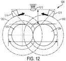
- FIGURE 12 illustrates a cross-sectional view of a second example of two air knives 1214 and 1216 whose positioning and geography are defined by the pair of counter-rotating rollers 1202 and 1204, the spray cone, and the target 1212 (e.g., nozzle) in accordance with certain embodiments of the disclosed technology.
- the location and positioning of the air knives 1214 and 1216 are defined at least in part by a distance from the counter-rotating rollers 1202 and 1204 as illustrated by respectively corresponding concentric circles 1203 and 1205 and equally by collocation of air knives 1214 and 1216 along the spray cone.
- the air knives 1214 and 1216 are positioned at the intersection of the spray cone and concentric circle from the roller and oriented such that the air flow through them is tangential to the concentric circles 1203 and 1205, respectively.
- each of the air knives 1214 and 1216 is based on the spray cone emanating from the counter-rotating rollers 1202 and 1204 such that the air knives 1214 and 1216 direct air against the spray cone with the effect of reducing its splay. Further, the orientation of each of the air knives 1214 and 1216 is based on its distance from the closest counter-rotating roller 1202 and 1204, respectively, as represented by the concentric circles 1203 and 1205, respectively.
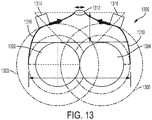
- FIGURE 13 illustrates a cross-sectional view of a second example of a collection shell whose curvature is defined by the pair of counter-rotating rollers, the spray cone, and the target in accordance with certain embodiments of the disclosed technology.
- shape e.g., curvature
- location/positioning of the air knives 1314 and 1316 are defined at least in part by a distance from the counter-rotating rollers 1302 and 1304 as illustrated by respectively corresponding concentric circles 1303 and 1305.
- the air knives 1314 and 1316 are positioned at the intersection of the spray cone and concentric circle from the roller and oriented such that the air flow through them into the interior of the collection shell 1310 is tangential to the concentric circles 1303 and 1305, respectively.
- each of the air knives 1314 and 1316 is based on the spray cone emanating from the counter-rotating rollers 1302 and 1304 such that the air knives 1314 and 1316 direct air against the spray cone with the effect of reducing its splay. Further, the orientation of each of the air knives 1314 and 1316 is based on its distance from the closest counter-rotating roller 1302 and 1304, respectively, as represented by the concentric circles 1303 and 1305, respectively.
Landscapes
- Health & Medical Sciences (AREA)
- Chemical & Material Sciences (AREA)
- Life Sciences & Earth Sciences (AREA)
- Engineering & Computer Science (AREA)
- Animal Behavior & Ethology (AREA)
- Public Health (AREA)
- General Health & Medical Sciences (AREA)
- Veterinary Medicine (AREA)
- Organic Chemistry (AREA)
- Heart & Thoracic Surgery (AREA)
- Biomedical Technology (AREA)
- Chemical Kinetics & Catalysis (AREA)
- Anesthesiology (AREA)
- Hematology (AREA)
- General Engineering & Computer Science (AREA)
- Vascular Medicine (AREA)
- Medicinal Chemistry (AREA)
- Mechanical Engineering (AREA)
- Microbiology (AREA)
- Dispersion Chemistry (AREA)
- Ophthalmology & Optometry (AREA)
- Pharmacology & Pharmacy (AREA)
- Nozzles (AREA)
- Special Spraying Apparatus (AREA)
- Application Of Or Painting With Fluid Materials (AREA)
- Details Or Accessories Of Spraying Plant Or Apparatus (AREA)
- Organic Low-Molecular-Weight Compounds And Preparation Thereof (AREA)
- Addition Polymer Or Copolymer, Post-Treatments, Or Chemical Modifications (AREA)
- Medicinal Preparation (AREA)
Abstract
Description
- The disclosed methods and systems generally relate to spray deposition systems and methods and more specifically to the controlled collection and direction of such spray in such systems.
- Many manufacturing and industrial applications benefit from fluid atomization to create a fine vapor mist or aerosol, such as the fuel/air mixture used in combustion applications, atomized air-paint mixtures for spray painting, application of coatings to pharmaceuticals, adhesive applications, and the like. Once a component solution is made into an aerosol it can be readily processed to coat virtually any shaped surface. Alternatively, in the pharmaceutical industry, aerosols are commonly used in a process called "spray-drying" to create fine powders that serve as upstream component solutions to create active pharmaceutical ingredients.
- Regarding prior techniques for the spray processing of viscoelastic fluids, such fluids often exhibit strain hardening behavior that suppresses droplet formation in conventional atomization methods. Some systems take advantage of this strain hardening behavior and harness it to generate droplets through an elastocapillary instability.
FIGURE 14 illustrates an example of such asystem 1400 that includes a spray mechanism having twocounter rotating rollers - Existing technologies can work with large rollers or small rollers. For example, whereas large rollers may be used for high throughput applications (e.g., as a unit operation at the end of a manufacturing line for producing droplets or powders), small rollers may be used for smaller output but at an equally small device footprint (e.g., as a handheld device for precision dispensing).
- The collection of the spray produced is generally integral to the spray technology. The spray droplets tend to naturally follow their own trajectory based on their initial velocity (e.g., upon filament break-up) and droplet size. These trajectory lines often follow a
spray cone 1410. Depending on different parameters such as the roller diameter, roller speeds, contact force, and the fluid rheology, thisspray cone 1410 is usually wide enough to make controlled deposition on a limited difficult. -
FIGURE 15 illustrates asystem 1500 for obtaining controlled deposition on a limited area that includes the use of a mask 1504 (or, alternatively, a sheet with an orifice) to block the unwanted spray fraction of thespray cone 1510 from thespray source 1502, such as a pair of counter-rotating rollers. While thissystem 1500 may limit the delivery area to alimited space 1512 on asurface 1520, the system is also significantly inefficient in that most of the unwanted spray collects on the mask 1504 (or sheet). - Over time, this collected volume will accumulate and likely eventually drip, which would be unsanitary for particular applications (e.g., the application of drug formulations and consumer products). This
system 1500 is also wasteful, particularly for high value fluids that are only available in limited volumes (e.g., specialized drugs and bioactives manufactured in the µg scale). - Therefore, methods and systems that reduce the amount of wasted spray would be beneficial in the art.
-
FIGURE 1 is a functional diagram illustrating an example of an aerosol producing system in accordance with certain embodiments of the disclosed technology. -
FIGURE 2 illustrates a first example of an aerosol producing system in accordance with certain embodiments of the disclosed technology. -
FIGURE 3 illustrates an example of a collection shell nozzle that has an elliptical opening that is perpendicular to the splay angle in accordance with certain embodiments of the disclosed technology. -
FIGURE 4 illustrates an example of a collection shell nozzle that has an elliptical opening that is parallel to the splay angle in accordance with certain embodiments of the disclosed technology. -
FIGURE 5 illustrates an example of a collection shell nozzle that has a circular opening in accordance with certain embodiments of the disclosed technology. -
FIGURE 6 illustrates a second example of an aerosol producing system in accordance with certain embodiments of the disclosed technology. -
FIGURE 7 illustrates a third example of an aerosol producing system in accordance with certain embodiments of the disclosed technology. -
FIGURE 8 illustrates a perspective cross-sectional view of two air knives integrated with a collection shell in accordance with certain embodiments of the disclosed technology. -
FIGURE 9 illustrates a side cross-sectional view of two air knives integrated with a collection shell in accordance with certain embodiments of the disclosed technology. -
FIGURE 10 illustrates a cross-sectional view of a first example of two air knives whose positioning and geography are defined by the pair of counter-rotating rollers, the spray cone, and the target in accordance with certain embodiments of the disclosed technology. -
FIGURE 11 illustrates a cross-sectional view of a first example of a collection shell whose curvature is defined by the pair of counter-rotating rollers, the spray cone, and the target in accordance with certain embodiments of the disclosed technology. -
FIGURE 12 illustrates a cross-sectional view of a second example of two air knives whose positioning and geography are defined by the pair of counter-rotating rollers, the spray cone, and the target in accordance with certain embodiments of the disclosed technology. -
FIGURE 13 illustrates a cross-sectional view of a second example of a collection shell whose curvature is defined by the pair of counter-rotating rollers, the spray cone, and the target in accordance with certain embodiments of the disclosed technology. -
FIGURE 14 illustrates an example of a prior atomizer for the spray processing of viscoelastic fluids. -
FIGURE 15 illustrates an example of a prior system for obtaining controlled deposition on a limited area that includes the use of a mask. - Embodiments of the disclosed technology are generally directed to systems and methods for the efficient collection of the spray produced in spray processing. Such embodiments may include a downscaled system, e.g., a system having 5-50mm rollers, and may include a collection shell leading to a nozzle having a suitable geometry and controlled air flow using air knives positioned and oriented to increase collection of the spray therethrough.
- Embodiments of the disclosed technology may advantageously enable the collection of a large portion, e.g., up to or over 85%, of the liquid that is input into the system. Prior systems have efficiencies less than 1% in larger roller systems (e.g., greater than 50mm roller diameter) and at 10% in smaller roller systems (e.g., less than 50mm roller diameter). Certain embodiments in accordance with the disclosed technology may further focus the spray into a defined and limited area, e.g., an area of the order of 1-2 cm2, which is comparable to the exposed surface area of the human eye.
-
FIGURE 1 is a functional diagram illustrating an example of anaerosol producing system 100 in accordance with certain embodiments of the disclosed technology. In the example, thesystem 100 has a pair ofcounter-rotating rollers rollers - In the example, the
system 100 also includes a pair ofair knives nozzle 112. Theair knives nozzle 112. The air flow induced by theair knives -
FIGURE 2 illustrates a first example of anaerosol producing system 200 in accordance with certain embodiments of the disclosed technology. In the example, thesystem 200 has a pair ofcounter-rotating rollers collection shell 210 around therollers collection shell 210 has a converging profile designed to guide the spray produced at the nip (e.g., the point of roller contact) into a nozzle 212 (e.g., exit port) that is integrated with thecollection shell 210. - In the example, the
system 200 also includes a pair ofair knives nozzle 212. As used herein, the term air knife generally refers to a device or component having a narrow opening through which air may be forced, e.g., by a certain type of fan or blower or other suitable device. - The
air knives air knives air knives collection shell 210. - Determination and maintenance of the amount air flow in the system is integral for guiding the spray and minimizing spray deposition in the shell surface near the nozzle. The air flow from the
air knives collection shell 210 that prevent particles from impinging and collecting on the surface. There is typically a critical level of air flow through theair knives nozzle 212. If the air flow is below or above this value, the spray collection efficiency is usually suboptimal. - In the example, the
nozzle 212 may be modular and readily interchangeable with the rest of thesystem 200. For example, thenozzle 212 may be positioned on thecollection shell 210 and secured by any suitable securing mechanism. The geometry of thenozzle 212 can be modified depending on the intended deposition area, e.g., with respect to the nascent spray profile. - For certain applications (e.g., ocular deposition), the nozzle geometry may be selected to more closely match the exposed surface area of the eye. Such selection may also have a slight effect on the collection efficiency given the natural splay of the spray cone, for example. The design of the
collection shell 210 and focusing of air flow by way of theair knives -
FIGURES 3-5 illustrate three different types of nozzle geometries that may be implemented.FIGURE 3 illustrates anozzle 312 having anelliptical opening 314 that is perpendicular to the splay angle,FIGURE 4 illustrates anozzle 422 having anelliptical opening 424 that is parallel to the splay angle, andFIGURE 5 illustrates anozzle 532 having acircular opening 534. It should be noted that the factor difference between the exit port geometries is generally small given the already large spray collection yield. -
FIGURE 6 illustrates a second example of anaerosol producing system 600 in accordance with certain embodiments of the disclosed technology. Similar to thesystem 200 illustrated byFIGURE 2 , thesystem 600 includes a pair ofcounter-rotating rollers collection shell 610 having anozzle 612, and a pair ofair knives nozzle 612. It should be noted that thecollection shell 610 ofFIGURE 6 has a different shape (e.g., curvature) than thecollection shell 210 illustrated byFIGURE 2 . - In certain embodiments, optimal air flow for the
collection shell 210 ofFIGURE 2 may be approximately 20-30 standard cubic feet per hour whereas the optimal air flow for thecollection shell 610 ofFIGURE 6 is approximately 40-50 standard cubic feet per hour. At these air flows, the spray collection efficiency can increase to as high as 85% or even greater. -
FIGURE 7 illustrates a third example of anaerosol producing system 700 in accordance with certain embodiments of the disclosed technology. In the example, acollection shell 710 having anozzle 712 is created, e.g., by way of three-dimensional (3D) printing, with a design and geometry that is based on the natural spray cone resulting from therollers - In the example, the
collection shell 710 is configured to fit and enclose the rollers in a benchtop test bed and direct the spray to a limited area. Thecollection shell 710 may be connected to an external clean air source and a flow meter with a needle valve used to regulate the inlet pressure (e.g., effective volume flow rate) into the air knives. - In certain embodiments, a collection shell may be integrated in a handheld system. The curvature and design of the collection shell and nozzle and the optimized air flow may ensure that the produced spray is directed into the desired area, such as the exposed surface of the human eye of a patient, for example. Other implementations may include, but are not limited to, coating the surface of a patient's mouth or nose (e.g., for oral/nasal fluid delivery), certain spots in the skin (e.g., for applying cosmetics), or a much larger area (e.g., for applying coatings).
- Certain implementations may include designing a collection shell for collecting and conveying droplets from other spray sources having different spray cone profiles (e.g., a wide splay in both planes, or true conical spray profiles). Also, nozzle shapes may be designed for other applications where different degrees of redirection may be needed, e.g., in the application of particular types of coatings.
-
FIGURE 8 illustrates a perspective cross-sectional view of twoair knives collection shell 810 in accordance with certain embodiments of the disclosed technology. In the example, two air-movingdevices air knives air knives collection shell 810 as indicated by the arrows. -
FIGURE 9 illustrates a side cross-sectional view of twoair knives collection shell 910 in accordance with certain embodiments of the disclosed technology. In the example, air is moved through theair knives collection shell 910 as indicated by the arrows. - In certain implementations, the position/location and orientation of each of the air knives may be determined based on any of a number of particular factors. For example, the position/location of each air knife may be based on the spray cone such that, no matter how far the air knife is located away from the roller surface, the air knife will still be along the spray cone. The orientation of each air knife, which generally controls the direction of the air flow that is induced by the air knife, is then selected such that the air flow is tangential to a circle concentric with the roller and simultaneously against the direction of the spray cone, for example. The effect of this position and orientation is reduction of the splay of the spray cone.
-
FIGURE 10 illustrates a cross-sectional view of a first example 1000 of twoair knives counter-rotating rollers air knives counter-rotating rollers concentric circles air knives air knives concentric circles - In the example 1000, the position/location of each of the
air knives counter-rotating rollers air knives air knives closest counter-rotating roller concentric circles -
FIGURE 11 illustrates a cross-sectional view of a first example 1100 of acollection shell 1110 whose curvature is defined by the pair ofcounter-rotating rollers target 1112 in accordance with certain embodiments of the disclosed technology. In the example, the shape (e.g., curvature) of thecollection shell 1110 and location/positioning of theair knives counter-rotating rollers concentric circles air knives collection shell 1110 is tangential to theconcentric circles - In the example 1100, the position/location of each of the
air knives counter-rotating rollers air knives air knives closest counter-rotating roller concentric circles -
FIGURE 12 illustrates a cross-sectional view of a second example of twoair knives counter-rotating rollers air knives counter-rotating rollers concentric circles air knives air knives concentric circles - In the example 1200, the position/location of each of the
air knives counter-rotating rollers air knives air knives closest counter-rotating roller concentric circles -
FIGURE 13 illustrates a cross-sectional view of a second example of a collection shell whose curvature is defined by the pair of counter-rotating rollers, the spray cone, and the target in accordance with certain embodiments of the disclosed technology. In the example, the shape (e.g., curvature) of thecollection shell 1310 and location/positioning of theair knives counter-rotating rollers concentric circles air knives collection shell 1310 is tangential to theconcentric circles - In the example 1300, the position/location of each of the
air knives counter-rotating rollers air knives air knives closest counter-rotating roller concentric circles
Claims (20)
- An aerosol creation system, comprising:a pair of counter-rotating rollers configured to be positioned adjacent each other and define a nip between each other, the nip having an upstream side and a downstream side;a fluid source configured to provide a fluid to the upstream side of the nip;a driving element configured to drive the pair of counter-rotating rollers to rotate in counter rotation with respect to each other and cause the fluid to be drawn through the upstream side of the nip to the downstream side of the nip and leave the downstream side of the nip as filaments that will break up into droplets; anda collection shell configured to be positioned substantially around the pair of counter-rotating rollers, the collection shell having a nozzle configured to allow passage of the spray from the downstream side of the nip.
- The aerosol creation system of claim 1, wherein the collection shell is designed based on a spray cone that is defined by the size of the counter-rotating rollers, the speed of their rotation, and the spray behavior of the fluid being dispensed into the nip.
- The aerosol creation system of claim 1, wherein the collection shell is modular and readily integratable with the system.
- The aerosol creation system of claim 3, wherein the collection shell is further readily removable from the system.
- The aerosol creation system of claim 2, further comprising a pair of air knives configured to create an air flow in a chamber that is substantially defined between an inner surface of the collection shell and the pair of counter-rotating rollers, wherein the air flow carries the droplets out through the nozzle.
- The aerosol creation system of claim 5, wherein the air flow is within a range of 3-30 standard cubic feet per hour.
- The aerosol creation system of claim 5, wherein the positioning and orientation of each of the air knives is based on a spray cone corresponding to the pair of counter-rotating rollers and defined by the size of the rollers, the rotation of the rollers, and the spray behavior of the fluid being dispensed into the nip.
- The aerosol creation system of claim 1, wherein the collection shell is created by way of one of a group consisting of: three-dimensional (3D) printing, machining, and injection molding.
- The aerosol creation system of claim 1, wherein the nozzle is selectable based on a spray cone corresponding to the pair of counter-rotation rollers.
- The aerosol creation system of claim 1, wherein the nozzle is configured to direct the spray from the downstream side of the nip to a limited area through an opening of the nozzle.
- The aerosol creation system of claim 10, wherein the limited area is a surface of a patient's eye.
- The aerosol creation system of claim 5, wherein at least one of the air knives has air driven therethrough by one of a group consisting of: a fan, a compressed air cannister, and a pressurized air line.
- The aerosol creation system of claim 1, wherein the system is a handheld device.
- The aerosol creation system of claim 1, wherein the nozzle is modular and readily integratable with the collection shell.
- The aerosol creation system of claim 1, further comprising another collection shell that is configured to replace the collection shell.
- A process of creating an aerosol, comprising:providing a fluid to a nip defined between a pair of counter-rotating rollers;rotating the counter-rotating rollers to cause the fluid to be drawn into an upstream side of the nip and create a spray from a downstream side of the nip;using a collection shell to direct the spray to a limited area by way of a nozzle.
- The process of claim 16, further comprising using at least one air knife to direct the spray within a chamber defined between the collection shell and the pair of counter-rotating rollers and expel the spray through the nozzle, wherein the positioning and orientation of the at least one air knife is based on a spray cone corresponding to the counter-rotating rollers and defined by the size of the rollers, the rotation of the rollers, and the spray behavior of the fluid being dispensed into the nip.
- The process of claim 16, further comprising designing the collection shell based on a spray cone corresponding to the pair of counter-rotating rollers.
- The process of claim 16, further comprising replacing the nozzle with another nozzle.
- The process of claim 16, further comprising replacing the collection shell with another collection shell.
Applications Claiming Priority (1)
| Application Number | Priority Date | Filing Date | Title |
|---|---|---|---|
| US15/962,580 US10953425B2 (en) | 2018-04-25 | 2018-04-25 | Methods and systems for collecting droplets of strain hardening viscoelastic fluids in a spray |
Publications (2)
| Publication Number | Publication Date |
|---|---|
| EP3560605A1 true EP3560605A1 (en) | 2019-10-30 |
| EP3560605B1 EP3560605B1 (en) | 2021-06-09 |
Family
ID=66239999
Family Applications (1)
| Application Number | Title | Priority Date | Filing Date |
|---|---|---|---|
| EP19170434.5A Active EP3560605B1 (en) | 2018-04-25 | 2019-04-19 | Methods and systems for collecting droplets of strain hardening viscoelastic fluids in a spray |
Country Status (5)
| Country | Link |
|---|---|
| US (1) | US10953425B2 (en) |
| EP (1) | EP3560605B1 (en) |
| JP (1) | JP7132881B2 (en) |
| KR (1) | KR102423318B1 (en) |
| CN (1) | CN110393838B (en) |
Families Citing this family (3)
| Publication number | Priority date | Publication date | Assignee | Title |
|---|---|---|---|---|
| US10953425B2 (en) * | 2018-04-25 | 2021-03-23 | Palo Alto Research Center Incorporated | Methods and systems for collecting droplets of strain hardening viscoelastic fluids in a spray |
| US11909052B2 (en) | 2021-06-30 | 2024-02-20 | Xerox Corporation | Fabrication of membrane electrode assembly with filament extension atomizer spray |
| US11826695B2 (en) * | 2021-10-25 | 2023-11-28 | Xerox Corporation | System and method to separate gases using high viscosity liquid sorbents in a spray contactor |
Citations (1)
| Publication number | Priority date | Publication date | Assignee | Title |
|---|---|---|---|---|
| EP3124122A1 (en) * | 2015-07-29 | 2017-02-01 | Palo Alto Research Center, Incorporated | Filament extension atomizers |
Family Cites Families (28)
| Publication number | Priority date | Publication date | Assignee | Title |
|---|---|---|---|---|
| US2291046A (en) * | 1942-07-28 | Arrangement for burning liquid fuel | ||
| US3873025A (en) * | 1974-05-06 | 1975-03-25 | Stora Kopparbergs Bergslags Ab | Method and apparatus for atomizing a liquid medium and for spraying the atomized liquid medium in a predetermined direction |
| US4034670A (en) * | 1975-03-24 | 1977-07-12 | Rockwell International Corporation | Dampening device for lithographic printing press |
| US4078725A (en) * | 1976-07-06 | 1978-03-14 | Peter Bauer | Spray apparatus |
| JPS5363419A (en) * | 1976-11-18 | 1978-06-06 | Asahi Glass Co Ltd | Spraying appratus for grc |
| US4106429A (en) * | 1977-05-23 | 1978-08-15 | Beloit Corporation | Air knife with adjustable lip |
| DE3019459A1 (en) * | 1980-05-21 | 1981-11-26 | Agfa-Gevaert Ag, 5090 Leverkusen | DEVICE AND METHOD FOR ELIMINATING CROSS THICKNESSES OF THE COATING THAT HAVE ARRANGED TO THE PATH |
| FR2726288B1 (en) * | 1994-10-27 | 1997-01-17 | Clecim Sa | AIR BLADE DEVICE FOR ADJUSTING THE THICKNESS OF A DEPOSIT |
| US5800652A (en) * | 1995-05-09 | 1998-09-01 | Paper Converting Machine Co. | Method and apparatus for tail sealing of convolutely wound webs |
| JPH10128199A (en) * | 1996-10-25 | 1998-05-19 | Sony Corp | Chemical coating device |
| SE516892C2 (en) * | 1999-12-15 | 2002-03-19 | Btg Pulp And Paper Technology | Method and apparatus for removing edge excess when coating runway |
| GB0025624D0 (en) * | 2000-10-19 | 2000-12-06 | Intersurgical Ltd | Chemical absorbent |
| AR032923A1 (en) * | 2001-03-02 | 2003-12-03 | James Hardie Int Finance Bv | APPLIANCE TO SPLASH. |
| JP2002273299A (en) * | 2001-03-22 | 2002-09-24 | Fuji Photo Film Co Ltd | Coating device and coating method |
| US8135321B2 (en) * | 2009-02-27 | 2012-03-13 | Xerox Corporation | Gas knife apparatus and methods for stripping media from surface in printing apparatus |
| US9639050B2 (en) * | 2012-07-12 | 2017-05-02 | Xerox Corporation | Electrophotographic patterning of an image definition material |
| US9643201B2 (en) * | 2013-06-17 | 2017-05-09 | The Boeing Company | High viscosity fluid dispensing system |
| US9962673B2 (en) * | 2013-10-29 | 2018-05-08 | Palo Alto Research Center Incorporated | Methods and systems for creating aerosols |
| US10016777B2 (en) * | 2013-10-29 | 2018-07-10 | Palo Alto Research Center Incorporated | Methods and systems for creating aerosols |
| US9527056B2 (en) * | 2014-05-27 | 2016-12-27 | Palo Alto Research Center Incorporated | Methods and systems for creating aerosols |
| US9707588B2 (en) * | 2014-05-27 | 2017-07-18 | Palo Alto Research Center Incorporated | Methods and systems for creating aerosols |
| US9757747B2 (en) * | 2014-05-27 | 2017-09-12 | Palo Alto Research Center Incorporated | Methods and systems for creating aerosols |
| US9878493B2 (en) * | 2014-12-17 | 2018-01-30 | Palo Alto Research Center Incorporated | Spray charging and discharging system for polymer spray deposition device |
| US9782790B2 (en) * | 2014-12-18 | 2017-10-10 | Palo Alto Research Center Incorporated | Devices and methods for the controlled formation and dispension of small drops of highly viscous and/or non-newtonian liquids |
| EP3088090B1 (en) * | 2015-04-30 | 2019-09-04 | HINTERKOPF GmbH | Varnishing device and method of coating an external surface of a varnishing object |
| US9707577B2 (en) * | 2015-07-29 | 2017-07-18 | Palo Alto Research Center Incorporated | Filament extension atomizers |
| US10493483B2 (en) * | 2017-07-17 | 2019-12-03 | Palo Alto Research Center Incorporated | Central fed roller for filament extension atomizer |
| US10953425B2 (en) * | 2018-04-25 | 2021-03-23 | Palo Alto Research Center Incorporated | Methods and systems for collecting droplets of strain hardening viscoelastic fluids in a spray |
-
2018
- 2018-04-25 US US15/962,580 patent/US10953425B2/en active Active
-
2019
- 2019-03-29 JP JP2019067028A patent/JP7132881B2/en active Active
- 2019-04-05 CN CN201910275448.7A patent/CN110393838B/en active Active
- 2019-04-05 KR KR1020190039904A patent/KR102423318B1/en active Active
- 2019-04-19 EP EP19170434.5A patent/EP3560605B1/en active Active
Patent Citations (1)
| Publication number | Priority date | Publication date | Assignee | Title |
|---|---|---|---|---|
| EP3124122A1 (en) * | 2015-07-29 | 2017-02-01 | Palo Alto Research Center, Incorporated | Filament extension atomizers |
Also Published As
| Publication number | Publication date |
|---|---|
| EP3560605B1 (en) | 2021-06-09 |
| US20190329278A1 (en) | 2019-10-31 |
| KR20190124135A (en) | 2019-11-04 |
| CN110393838B (en) | 2022-02-11 |
| JP7132881B2 (en) | 2022-09-07 |
| KR102423318B1 (en) | 2022-07-22 |
| US10953425B2 (en) | 2021-03-23 |
| CN110393838A (en) | 2019-11-01 |
| JP2019188392A (en) | 2019-10-31 |
Similar Documents
| Publication | Publication Date | Title |
|---|---|---|
| CA2377566C (en) | Low spray force, low retention atomization system | |
| US11311900B2 (en) | Methods and systems for creating aerosols | |
| EP3560605B1 (en) | Methods and systems for collecting droplets of strain hardening viscoelastic fluids in a spray | |
| US12202001B2 (en) | Methods and systems for creating aerosols | |
| US10130960B2 (en) | Swirl nozzle assemblies with high efficiency mechanical break up for generating mist sprays of uniform small droplets | |
| US9962673B2 (en) | Methods and systems for creating aerosols | |
| EP2195055B1 (en) | Ultrasonic atomizing nozzle with variable fan-spray feature | |
| EP2949401B1 (en) | Methods and systems for creating aerosols | |
| AU2014408517B2 (en) | Pneumatic atomizing nozzle | |
| US20170259280A1 (en) | Filament extension atomizers | |
| CN103301970B (en) | Liquid injecting type micro-point mist jet device | |
| EP3124124B1 (en) | Filament extension atomizers | |
| EP3641945B1 (en) | Multiliquid-nozzle | |
| CN115038525B (en) | Nozzle for spraying mist liquid | |
| JP2019188392A5 (en) | ||
| WO2018234524A1 (en) | Multiliquid-nozzle | |
| CN116635155A (en) | Two-fluid nozzle with curved opening |
Legal Events
| Date | Code | Title | Description |
|---|---|---|---|
| PUAI | Public reference made under article 153(3) epc to a published international application that has entered the european phase |
Free format text: ORIGINAL CODE: 0009012 |
|
| STAA | Information on the status of an ep patent application or granted ep patent |
Free format text: STATUS: THE APPLICATION HAS BEEN PUBLISHED |
|
| AK | Designated contracting states |
Kind code of ref document: A1 Designated state(s): AL AT BE BG CH CY CZ DE DK EE ES FI FR GB GR HR HU IE IS IT LI LT LU LV MC MK MT NL NO PL PT RO RS SE SI SK SM TR |
|
| AX | Request for extension of the european patent |
Extension state: BA ME |
|
| STAA | Information on the status of an ep patent application or granted ep patent |
Free format text: STATUS: REQUEST FOR EXAMINATION WAS MADE |
|
| 17P | Request for examination filed |
Effective date: 20200430 |
|
| RBV | Designated contracting states (corrected) |
Designated state(s): AL AT BE BG CH CY CZ DE DK EE ES FI FR GB GR HR HU IE IS IT LI LT LU LV MC MK MT NL NO PL PT RO RS SE SI SK SM TR |
|
| STAA | Information on the status of an ep patent application or granted ep patent |
Free format text: STATUS: EXAMINATION IS IN PROGRESS |
|
| 17Q | First examination report despatched |
Effective date: 20200918 |
|
| GRAP | Despatch of communication of intention to grant a patent |
Free format text: ORIGINAL CODE: EPIDOSNIGR1 |
|
| STAA | Information on the status of an ep patent application or granted ep patent |
Free format text: STATUS: GRANT OF PATENT IS INTENDED |
|
| RIC1 | Information provided on ipc code assigned before grant |
Ipc: B05B 7/00 20060101ALI20201104BHEP Ipc: B05B 3/02 20060101ALI20201104BHEP Ipc: F26B 3/12 20060101ALI20201104BHEP Ipc: B05B 12/32 20180101ALI20201104BHEP Ipc: B05B 12/18 20180101ALI20201104BHEP Ipc: B05B 12/20 20180101ALN20201104BHEP Ipc: B05B 3/08 20060101ALI20201104BHEP Ipc: B05B 17/04 20060101AFI20201104BHEP Ipc: B01J 13/00 20060101ALI20201104BHEP |
|
| INTG | Intention to grant announced |
Effective date: 20201207 |
|
| GRAS | Grant fee paid |
Free format text: ORIGINAL CODE: EPIDOSNIGR3 |
|
| GRAA | (expected) grant |
Free format text: ORIGINAL CODE: 0009210 |
|
| STAA | Information on the status of an ep patent application or granted ep patent |
Free format text: STATUS: THE PATENT HAS BEEN GRANTED |
|
| AK | Designated contracting states |
Kind code of ref document: B1 Designated state(s): AL AT BE BG CH CY CZ DE DK EE ES FI FR GB GR HR HU IE IS IT LI LT LU LV MC MK MT NL NO PL PT RO RS SE SI SK SM TR |
|
| REG | Reference to a national code |
Ref country code: GB Ref legal event code: FG4D |
|
| REG | Reference to a national code |
Ref country code: CH Ref legal event code: EP Ref country code: AT Ref legal event code: REF Ref document number: 1400029 Country of ref document: AT Kind code of ref document: T Effective date: 20210615 |
|
| REG | Reference to a national code |
Ref country code: DE Ref legal event code: R096 Ref document number: 602019005175 Country of ref document: DE |
|
| REG | Reference to a national code |
Ref country code: IE Ref legal event code: FG4D |
|
| REG | Reference to a national code |
Ref country code: LT Ref legal event code: MG9D |
|
| PG25 | Lapsed in a contracting state [announced via postgrant information from national office to epo] |
Ref country code: FI Free format text: LAPSE BECAUSE OF FAILURE TO SUBMIT A TRANSLATION OF THE DESCRIPTION OR TO PAY THE FEE WITHIN THE PRESCRIBED TIME-LIMIT Effective date: 20210609 Ref country code: HR Free format text: LAPSE BECAUSE OF FAILURE TO SUBMIT A TRANSLATION OF THE DESCRIPTION OR TO PAY THE FEE WITHIN THE PRESCRIBED TIME-LIMIT Effective date: 20210609 Ref country code: LT Free format text: LAPSE BECAUSE OF FAILURE TO SUBMIT A TRANSLATION OF THE DESCRIPTION OR TO PAY THE FEE WITHIN THE PRESCRIBED TIME-LIMIT Effective date: 20210609 Ref country code: BG Free format text: LAPSE BECAUSE OF FAILURE TO SUBMIT A TRANSLATION OF THE DESCRIPTION OR TO PAY THE FEE WITHIN THE PRESCRIBED TIME-LIMIT Effective date: 20210909 |
|
| REG | Reference to a national code |
Ref country code: AT Ref legal event code: MK05 Ref document number: 1400029 Country of ref document: AT Kind code of ref document: T Effective date: 20210609 |
|
| REG | Reference to a national code |
Ref country code: NL Ref legal event code: MP Effective date: 20210609 |
|
| PG25 | Lapsed in a contracting state [announced via postgrant information from national office to epo] |
Ref country code: GR Free format text: LAPSE BECAUSE OF FAILURE TO SUBMIT A TRANSLATION OF THE DESCRIPTION OR TO PAY THE FEE WITHIN THE PRESCRIBED TIME-LIMIT Effective date: 20210910 Ref country code: SE Free format text: LAPSE BECAUSE OF FAILURE TO SUBMIT A TRANSLATION OF THE DESCRIPTION OR TO PAY THE FEE WITHIN THE PRESCRIBED TIME-LIMIT Effective date: 20210609 Ref country code: RS Free format text: LAPSE BECAUSE OF FAILURE TO SUBMIT A TRANSLATION OF THE DESCRIPTION OR TO PAY THE FEE WITHIN THE PRESCRIBED TIME-LIMIT Effective date: 20210609 Ref country code: NO Free format text: LAPSE BECAUSE OF FAILURE TO SUBMIT A TRANSLATION OF THE DESCRIPTION OR TO PAY THE FEE WITHIN THE PRESCRIBED TIME-LIMIT Effective date: 20210909 Ref country code: LV Free format text: LAPSE BECAUSE OF FAILURE TO SUBMIT A TRANSLATION OF THE DESCRIPTION OR TO PAY THE FEE WITHIN THE PRESCRIBED TIME-LIMIT Effective date: 20210609 |
|
| PG25 | Lapsed in a contracting state [announced via postgrant information from national office to epo] |
Ref country code: SK Free format text: LAPSE BECAUSE OF FAILURE TO SUBMIT A TRANSLATION OF THE DESCRIPTION OR TO PAY THE FEE WITHIN THE PRESCRIBED TIME-LIMIT Effective date: 20210609 Ref country code: EE Free format text: LAPSE BECAUSE OF FAILURE TO SUBMIT A TRANSLATION OF THE DESCRIPTION OR TO PAY THE FEE WITHIN THE PRESCRIBED TIME-LIMIT Effective date: 20210609 Ref country code: ES Free format text: LAPSE BECAUSE OF FAILURE TO SUBMIT A TRANSLATION OF THE DESCRIPTION OR TO PAY THE FEE WITHIN THE PRESCRIBED TIME-LIMIT Effective date: 20210609 Ref country code: PT Free format text: LAPSE BECAUSE OF FAILURE TO SUBMIT A TRANSLATION OF THE DESCRIPTION OR TO PAY THE FEE WITHIN THE PRESCRIBED TIME-LIMIT Effective date: 20211011 Ref country code: NL Free format text: LAPSE BECAUSE OF FAILURE TO SUBMIT A TRANSLATION OF THE DESCRIPTION OR TO PAY THE FEE WITHIN THE PRESCRIBED TIME-LIMIT Effective date: 20210609 Ref country code: RO Free format text: LAPSE BECAUSE OF FAILURE TO SUBMIT A TRANSLATION OF THE DESCRIPTION OR TO PAY THE FEE WITHIN THE PRESCRIBED TIME-LIMIT Effective date: 20210609 Ref country code: SM Free format text: LAPSE BECAUSE OF FAILURE TO SUBMIT A TRANSLATION OF THE DESCRIPTION OR TO PAY THE FEE WITHIN THE PRESCRIBED TIME-LIMIT Effective date: 20210609 Ref country code: AT Free format text: LAPSE BECAUSE OF FAILURE TO SUBMIT A TRANSLATION OF THE DESCRIPTION OR TO PAY THE FEE WITHIN THE PRESCRIBED TIME-LIMIT Effective date: 20210609 Ref country code: CZ Free format text: LAPSE BECAUSE OF FAILURE TO SUBMIT A TRANSLATION OF THE DESCRIPTION OR TO PAY THE FEE WITHIN THE PRESCRIBED TIME-LIMIT Effective date: 20210609 |
|
| PG25 | Lapsed in a contracting state [announced via postgrant information from national office to epo] |
Ref country code: PL Free format text: LAPSE BECAUSE OF FAILURE TO SUBMIT A TRANSLATION OF THE DESCRIPTION OR TO PAY THE FEE WITHIN THE PRESCRIBED TIME-LIMIT Effective date: 20210609 |
|
| REG | Reference to a national code |
Ref country code: DE Ref legal event code: R097 Ref document number: 602019005175 Country of ref document: DE |
|
| PLBE | No opposition filed within time limit |
Free format text: ORIGINAL CODE: 0009261 |
|
| STAA | Information on the status of an ep patent application or granted ep patent |
Free format text: STATUS: NO OPPOSITION FILED WITHIN TIME LIMIT |
|
| PG25 | Lapsed in a contracting state [announced via postgrant information from national office to epo] |
Ref country code: DK Free format text: LAPSE BECAUSE OF FAILURE TO SUBMIT A TRANSLATION OF THE DESCRIPTION OR TO PAY THE FEE WITHIN THE PRESCRIBED TIME-LIMIT Effective date: 20210609 |
|
| 26N | No opposition filed |
Effective date: 20220310 |
|
| PG25 | Lapsed in a contracting state [announced via postgrant information from national office to epo] |
Ref country code: AL Free format text: LAPSE BECAUSE OF FAILURE TO SUBMIT A TRANSLATION OF THE DESCRIPTION OR TO PAY THE FEE WITHIN THE PRESCRIBED TIME-LIMIT Effective date: 20210609 |
|
| PG25 | Lapsed in a contracting state [announced via postgrant information from national office to epo] |
Ref country code: IT Free format text: LAPSE BECAUSE OF FAILURE TO SUBMIT A TRANSLATION OF THE DESCRIPTION OR TO PAY THE FEE WITHIN THE PRESCRIBED TIME-LIMIT Effective date: 20210609 |
|
| REG | Reference to a national code |
Ref country code: CH Ref legal event code: PL |
|
| REG | Reference to a national code |
Ref country code: BE Ref legal event code: MM Effective date: 20220430 |
|
| PG25 | Lapsed in a contracting state [announced via postgrant information from national office to epo] |
Ref country code: MC Free format text: LAPSE BECAUSE OF FAILURE TO SUBMIT A TRANSLATION OF THE DESCRIPTION OR TO PAY THE FEE WITHIN THE PRESCRIBED TIME-LIMIT Effective date: 20210609 Ref country code: LU Free format text: LAPSE BECAUSE OF NON-PAYMENT OF DUE FEES Effective date: 20220419 Ref country code: LI Free format text: LAPSE BECAUSE OF NON-PAYMENT OF DUE FEES Effective date: 20220430 Ref country code: CH Free format text: LAPSE BECAUSE OF NON-PAYMENT OF DUE FEES Effective date: 20220430 |
|
| PG25 | Lapsed in a contracting state [announced via postgrant information from national office to epo] |
Ref country code: BE Free format text: LAPSE BECAUSE OF NON-PAYMENT OF DUE FEES Effective date: 20220430 |
|
| PG25 | Lapsed in a contracting state [announced via postgrant information from national office to epo] |
Ref country code: IE Free format text: LAPSE BECAUSE OF NON-PAYMENT OF DUE FEES Effective date: 20220419 |
|
| PG25 | Lapsed in a contracting state [announced via postgrant information from national office to epo] |
Ref country code: HU Free format text: LAPSE BECAUSE OF FAILURE TO SUBMIT A TRANSLATION OF THE DESCRIPTION OR TO PAY THE FEE WITHIN THE PRESCRIBED TIME-LIMIT; INVALID AB INITIO Effective date: 20190419 |
|
| PG25 | Lapsed in a contracting state [announced via postgrant information from national office to epo] |
Ref country code: MK Free format text: LAPSE BECAUSE OF FAILURE TO SUBMIT A TRANSLATION OF THE DESCRIPTION OR TO PAY THE FEE WITHIN THE PRESCRIBED TIME-LIMIT Effective date: 20210609 Ref country code: CY Free format text: LAPSE BECAUSE OF FAILURE TO SUBMIT A TRANSLATION OF THE DESCRIPTION OR TO PAY THE FEE WITHIN THE PRESCRIBED TIME-LIMIT Effective date: 20210609 |
|
| PG25 | Lapsed in a contracting state [announced via postgrant information from national office to epo] |
Ref country code: MT Free format text: LAPSE BECAUSE OF FAILURE TO SUBMIT A TRANSLATION OF THE DESCRIPTION OR TO PAY THE FEE WITHIN THE PRESCRIBED TIME-LIMIT Effective date: 20210609 |
|
| PG25 | Lapsed in a contracting state [announced via postgrant information from national office to epo] |
Ref country code: TR Free format text: LAPSE BECAUSE OF FAILURE TO SUBMIT A TRANSLATION OF THE DESCRIPTION OR TO PAY THE FEE WITHIN THE PRESCRIBED TIME-LIMIT Effective date: 20210609 |
|
| PGFP | Annual fee paid to national office [announced via postgrant information from national office to epo] |
Ref country code: GB Payment date: 20260319 Year of fee payment: 8 |
|
| PGFP | Annual fee paid to national office [announced via postgrant information from national office to epo] |
Ref country code: FR Payment date: 20260320 Year of fee payment: 8 |
|
| PGFP | Annual fee paid to national office [announced via postgrant information from national office to epo] |
Ref country code: DE Payment date: 20260319 Year of fee payment: 8 |