EP3560559A1 - Tennis racket with different mesh size - Google Patents
Tennis racket with different mesh size Download PDFInfo
- Publication number
- EP3560559A1 EP3560559A1 EP19165856.6A EP19165856A EP3560559A1 EP 3560559 A1 EP3560559 A1 EP 3560559A1 EP 19165856 A EP19165856 A EP 19165856A EP 3560559 A1 EP3560559 A1 EP 3560559A1
- Authority
- EP
- European Patent Office
- Prior art keywords
- mesh
- tennis racket
- center
- area
- tip
- Prior art date
- Legal status (The legal status is an assumption and is not a legal conclusion. Google has not performed a legal analysis and makes no representation as to the accuracy of the status listed.)
- Granted
Links
Images



Classifications
-
- A—HUMAN NECESSITIES
- A63—SPORTS; GAMES; AMUSEMENTS
- A63B—APPARATUS FOR PHYSICAL TRAINING, GYMNASTICS, SWIMMING, CLIMBING, OR FENCING; BALL GAMES; TRAINING EQUIPMENT
- A63B51/00—Stringing tennis, badminton or like rackets; Strings therefor; Maintenance of racket strings
- A63B51/02—Strings; String substitutes; Products applied on strings, e.g. for protection against humidity or wear
-
- A—HUMAN NECESSITIES
- A63—SPORTS; GAMES; AMUSEMENTS
- A63B—APPARATUS FOR PHYSICAL TRAINING, GYMNASTICS, SWIMMING, CLIMBING, OR FENCING; BALL GAMES; TRAINING EQUIPMENT
- A63B49/00—Stringed rackets, e.g. for tennis
- A63B49/02—Frames
-
- A—HUMAN NECESSITIES
- A63—SPORTS; GAMES; AMUSEMENTS
- A63B—APPARATUS FOR PHYSICAL TRAINING, GYMNASTICS, SWIMMING, CLIMBING, OR FENCING; BALL GAMES; TRAINING EQUIPMENT
- A63B51/00—Stringing tennis, badminton or like rackets; Strings therefor; Maintenance of racket strings
-
- A—HUMAN NECESSITIES
- A63—SPORTS; GAMES; AMUSEMENTS
- A63B—APPARATUS FOR PHYSICAL TRAINING, GYMNASTICS, SWIMMING, CLIMBING, OR FENCING; BALL GAMES; TRAINING EQUIPMENT
- A63B2102/00—Application of clubs, bats, rackets or the like to the sporting activity ; particular sports involving the use of balls and clubs, bats, rackets, or the like
- A63B2102/02—Tennis
-
- A—HUMAN NECESSITIES
- A63—SPORTS; GAMES; AMUSEMENTS
- A63B—APPARATUS FOR PHYSICAL TRAINING, GYMNASTICS, SWIMMING, CLIMBING, OR FENCING; BALL GAMES; TRAINING EQUIPMENT
- A63B51/00—Stringing tennis, badminton or like rackets; Strings therefor; Maintenance of racket strings
- A63B51/02—Strings; String substitutes; Products applied on strings, e.g. for protection against humidity or wear
- A63B51/023—Strings having characteristics varying along the length of the string, e.g. diameter or elasticity
Definitions
- the present invention relates to tennis rackets.
- JP2002-306639 discloses a tennis racket having an enlarged sweet area.
- the length L1 of the minimum interval between longitudinal strings and the length L2 of the minimum interval between transverse strings are each set within a predetermined range, and the ratio (L2/L1) of the length L2 to the length L1 is further set to be not less than 1.50 and not greater than 2.80.
- the mainstream swing in regulation-ball tennis is classical swing.
- the classical swing when a tennis racket hits a ball, the tennis racket is swung such that a hand grip portion and a tip portion thereof move substantially parallel to each other.
- modern swing is the mainstream swing.
- the modern swing when a tennis racket hits a ball, the tennis racket is swung such that a tip portion thereof moves faster than a hand grip portion thereof.
- a ball is hit at the vicinity of the tip portion that moves fast, whereby the ball can be strongly hit.
- the sweet spot is located substantially at the center of the ball-hitting face.
- the resilience performance at the vicinity of a tip portion is inferior to that of a center portion.
- An object of the present invention is to provide a tennis racket having, at a tip side from the center of a ball-hitting face thereof, an area having high resilience performance.
- longitudinal strings extending in a longitudinal direction and transverse strings extending in a transverse direction intersect each other to form a plurality of meshes.
- a ratio of an area St of a tip mesh located closest to a tip in the longitudinal direction relative to an area Sc of a center mesh located at a center in the longitudinal direction is not less than 1.6.
- the center mesh is formed in a rectangular shape having short sides in the longitudinal direction and long sides in the transverse direction.
- an area of each mesh is set so as to be not larger than an area of a mesh adjacent thereto at a tip side.
- the area of the mesh gradually increases from the center toward the tip.
- pitches between the longitudinal strings are constant in the transverse direction.
- Resilience amounts at positions at which a distance Y from a top of the head is 6 cm, 9 cm, 12 cm, and 15 cm are denoted by Hb 6 , Hb 9 , Hb 12 , and Hb 15 , respectively.
- a minimum resilience amount is not less than 0.98 times of a maximum resilience amount.
- the area Sc of the center mesh is not less than 70 mm 2 .
- a number of the longitudinal strings is not less than 16 and not greater than 18, and a number of the transverse strings is not less than 18 and not greater than 20.
- the ratio (St/Sc) of the area St of the tip mesh to the area Sc of the center mesh is increased without extremely decreasing the area of the center mesh. Since the ratio (St/Sc) is increased, high resilience performance is exhibited at the tip side.
- FIG. 1 shows a tennis racket 2 according to the present invention.
- the tennis racket 2 includes a racket frame 4, a string 6, a yoke 8, and a grip 10.
- the tennis racket 2 is used for regulation-ball tennis.
- the up-down direction is the longitudinal direction of the tennis racket 2
- the right-left direction is the transverse direction of the tennis racket 2
- a direction perpendicular to the surface of the sheet is the thickness direction of the tennis racket 2.
- the racket frame 4 includes a head 12, a pair of throats 14, and a shaft 16.
- the head 12, the pair of throats 14, and the shaft 16 are connected to each other.
- the head 12 extends in a curved manner so as to be bent back at the upper side.
- a pair of lower ends of the head 12 are connected to each other via the yoke 8. In this manner, the head 12 and the yoke 8 form an annular portion 18 having a substantially elliptical shape.
- Each throat 14 extends downward from the lower end of the head 12.
- the throats 14 extend toward the shaft 16 in directions in which the throats 14 come close to each other.
- Both end portions of the racket frame 4 extend downward further from the pair of throats 14. Both end portions are joined to each other. The joined end portions form the shaft 16.
- the grip 10 is formed at the outer side of the shaft 16.
- the string 6 is stretched on the annular portion 18 of the racket frame 4.
- the string 6 stretched on the annular portion 18 forms a plurality of longitudinal strings 20 and a plurality of transverse strings 22.
- These longitudinal strings 20 and these transverse strings 22 form a ball-hitting face 24.
- the ball-hitting face 24 has a substantially elliptical shape surrounded by the annular portion 18.
- the major axis direction of the ball-hitting face 24 is the longitudinal direction of the tennis racket 2.
- the minor axis direction of the ball-hitting face 24 is the transverse direction of the tennis racket 2.
- the string 6 forms, for example, 16 longitudinal strings 20, and, for example, 19 transverse strings 22.
- Each longitudinal string 20 extends in the longitudinal direction inside the annular portion 18.
- Each transverse string 22 extends in the transverse direction inside the annular portion 18.
- These longitudinal strings 20 and these transverse strings 22 intersect each other to form a plurality of meshes 26.
- the shape of each mesh 26 is a quadrangle surrounded by the longitudinal strings 20 and the transverse strings 22.
- FIG. 2 shows the longitudinal strings 20 and the transverse strings 22 stretched on the annular portion 18.
- an alternate long and short dash line Ly represents a center line of the ball-hitting face 24 that extends in the longitudinal direction of the head 12.
- the center line Ly extends through the center, in the transverse direction, of the head 12.
- the center line Ly is also a straight line that passes through a position at which the dimension, in the longitudinal direction, of the ball-hitting face 24 is at its maximum.
- An alternate long and short dash line Lx represents a center line of the ball-hitting face 24 that extends in the transverse direction of the head 12.
- reference character P0 represents the center position of the ball-hitting face 24.
- the center position P0 represents the midpoint of a line segment extending on the ball-hitting face 24, of the center line Ly.
- the center line Lx is a straight line that passes through the center position P0 and extends in the transverse direction.
- a point P1 represents the point of intersection of the annular portion 18 (head 12) and the center line Ly at the upper side. In the present invention, the point P1 is also referred to as a top of the head 12.
- a point P2 represents the point of intersection of the annular portion 18 (yoke 8) and the center line Ly.
- a point P3 represents one point of intersection of the annular portion 18 (head 12) and the center line Lx in the transverse direction.
- a point P4 represents the other point of intersection of the annular portion 18 (head 12) and the center line Lx in the transverse direction.
- a double-headed arrow x represents the interval between the longitudinal strings 20 in the transverse direction.
- the interval x is measured as the interval between the axes of the longitudinal strings 20 adjacent to each other in the transverse direction.
- a double-headed arrow y represents the interval between the transverse strings 22 in the longitudinal direction.
- the interval y is measured as the interval between the axes of the transverse strings 22 adjacent to each other in the longitudinal direction.
- Reference character S represents the area of a quadrangle formed by the longitudinal strings 20 and the transverse strings 22.
- the area S is obtained as the product of the interval x and the interval y. In the present invention, the area S is referred to as area of the mesh 26.
- the mesh 26 in which the center position P0 is located, among a large number of meshes 26, is referred to as a center mesh 26c.
- the mesh 26 that is closest to the top (point P1) of the head 12 is referred to as a tip mesh 26t.
- FIG. 3 shows an enlarged view of an area surrounded by an alternate long and two short dashes line III in FIG. 2 .
- double-headed arrows y1 to y11 represent the magnitudes of the longitudinal intervals y at the respective meshes 26.
- the longitudinal intervals y are specified in order of y1 to y11 from the tip side toward the hand grip side.
- the longitudinal intervals y are further specified as y12, y13, and y14 from Y11 toward the hand grip side.
- the double-headed arrow y1 represents the longitudinal interval y at the tip mesh 26t.
- the double-headed arrow y9 represents the longitudinal interval y at the center mesh 26c.
- the longitudinal intervals y8 to y11 are set so as to have the same magnitude.
- the longitudinal interval y gradually increases from the longitudinal interval y8 toward the longitudinal interval y1.
- the longitudinal interval y gradually increases from the longitudinal interval y11 toward the hand grip side.
- each double-headed arrow x1 represents the magnitude of the transverse interval x between the longitudinal strings 20.
- the transverse intervals x between the longitudinal strings 20 are set so as to be uniform as a transverse interval x1.
- the transverse interval x at the center mesh 26c and the transverse interval x at the tip mesh 26t are also each set to a transverse interval x1.
- reference characters S1 to S11 represent the areas S of the respective meshes 26.
- the areas S are specified in order of S1 to S11 from the tip side toward the hand grip side. Although not shown, the areas S are further specified as S12, S13, and S14 from S11 toward the hand grip side.
- the area S1 represents the area St of the tip mesh 26t.
- the area S9 represents the area Sc of the center mesh 26c.
- the areas S8, S9, S10, and S11 are set so as to have the same magnitude.
- the areas S8, S10, and S11 are set so as to have the same magnitude as the area Sc.
- the area S gradually increases from the area S8 toward the area St.
- the area S gradually increases from the area S11 toward the hand grip side.
- FIG. 4 is an explanatory diagram for a testing method for resilience performance. The testing method for the resilience performance of the tennis racket 2 will be described with reference to FIG. 4 .
- the tennis racket 2 is placed on a test stand 28.
- the test stand 28 has a flat placement surface 30.
- the placement surface 30 is a flat surface that extends in the horizontal direction.
- the head 12 and the yoke 8 are placed on the placement surface 30.
- the tennis racket 2 is placed such that the ball-hitting face 24 is parallel to the placement surface 30. In other words, the tennis racket 2 is placed such that the longitudinal strings 20 and the transverse strings 22 extend parallel to the placement surface 30.
- the tennis racket 2 is fixed to the test stand 28 by a cramp that is not shown.
- reference character Pf represents a point located on the ball-hitting face 24.
- the point Pf is located on the straight line Ly.
- a double-headed arrow Y represents the distance from the top (point P1) of the head 12 to the point Pf. The distance Y is measured along the ball-hitting face 24 in the longitudinal direction.
- a tennis ball is caused to freely fall from a position having a predetermined height H from the ball-hitting face 24 at the position of the distance Y.
- the tennis ball that has collided against the ball-hitting face 24 at the point Pf is rebounded.
- a resilience amount Hb of the rebounded tennis ball is measured.
- the resilience amount Hb is obtained as a maximum reach height of the tennis ball.
- the resilience amount Hb is obtained as a height from the ball-hitting face 24.
- the ratio (Hb/H) of the height Hb to the height H may be obtained.
- the ratio (Hb/H) is used as resilience performance. When the ratio (Hb/H) is greater, the resilience performance is higher.
- the height H is set to 254 cm.
- the heights H and Hb are each measured as a distance from the ball-hitting face 24 to the lower position (lower end position) of the tennis ball.
- the heights H and Hb are each measured as a direct distance in the thickness direction of the tennis racket 2.
- FIG. 5 shows a graph of a relationship between a distance Y from the top and an area ratio (S/Sc) in each of the tennis racket 2 and a conventional tennis racket.
- A is a graph of the area ratio (S/Sc) in the tennis racket 2
- B is a graph of the area ratio (S/Sc) in a commercially-available tennis racket as the conventional tennis racket.
- the center mesh 26c is located at a position at which the distance Y is 15 cm.
- a center mesh is located at a position at which the distance Y is 15 cm.
- the ratio (S/Sc) is obtained as the ratio of the area S of the mesh 26 located at the distance Y, relative to the area Sc of the center mesh 26c.
- the area ratio (S/Sc) increases as the position approaches the top from the center mesh 26c.
- the area ratio (S/Sc) in the tennis racket 2 is greater at the tip side than that in the conventional tennis racket.
- a mesh 26 having a large area S can bend more greatly when a tennis ball collides with the tennis racket 2, than a mesh 26 having a small area S.
- the greater bending produces greater resilient force.
- resilience performance at the tip side is improved by increasing the area ratio (S/Sc).
- FIG. 6 shows a relationship between a distance Y from the top and a resilience amount.
- FIG. 6 is obtained through measurement by the testing method for resilience performance in FIG. 4 .
- A is a graph of the resilience amount Hb of the tennis racket 2
- B is a graph of the resilience amount Hb of the commercially-available tennis racket.
- the resilience amount Hb increases from the lower side toward the upper side.
- a resilience amount Hb 6 at a position at which the distance Y from the top is 6 cm, a resilience amount Hb 9 at a position at which the distance Y from the top is 9 cm, and a resilience amount Hb 12 at a position at which the distance Y from the top is 12 cm are each larger than a resilience amount Hb 15 at the position at which the distance Y is 15 cm.
- the resilience amount Hb 6 , the resilience amount Hb 9 , and the resilience amount Hb 12 at the tip side of the ball-hitting face 24 are larger than the resilience amount Hb 15 at the center mesh 26c.
- the resilience amount Hb decreases as the distance Y from the top decreases.
- the longitudinal interval y9 at the center mesh 26c is set so as to be less than the transverse interval x1 at the center mesh 26c.
- the magnitude of the longitudinal interval at the center mesh is generally set so as to be greater than that of the transverse interval at the center mesh in the conventional tennis racket. Accordingly, in the tennis racket 2, the ratio (St/Sc) of the area St at the tip mesh 26t to the area Sc at the center mesh 26c can be greater than that in the conventional tennis racket.
- the ratio (St/Sc) is increased and set so as to be not less than 1.6.
- the ratio (St/Sc) is greater than that in the conventional tennis racket.
- high resilience performance is obtained at the vicinity of the tip mesh 26t. The tennis racket 2 can strongly hit a ball at the vicinity of the tip portion.
- the area S of the mesh 26 preferably increases gradually from the center side toward the tip side. In other words, from the center mesh 26c to the tip mesh 26t, the area S of the mesh 26 preferably increases gradually from the center toward the tip. Accordingly, a sudden change in resilience performance is inhibited. Thus, the resilience performance is made uniform from the center of the ball-hitting face 24 to the vicinity of the tip.
- the area Sc of the center mesh 26c, the area S8 of the mesh 26 adjacent to the center mesh 26c at the tip side, the area S10 of the mesh 26 adjacent to the center mesh 26c at the hand grip side, and the area S11 of the mesh 26 adjacent to the mesh 26 having the area S10 at the hand grip side are set so as to have the same magnitude.
- the area S does not necessarily have to gradually increase from the center mesh 26c to the tip mesh 26t.
- the areas S of meshes 26 adjacent to each other in the longitudinal direction may be partially set so as to be equal to each other.
- the area St of the tip mesh 26t only needs to be larger than the area Sc of the center mesh 26c, and the area S of each mesh 26 only needs to be not larger than the area S of the mesh 26 adjacent thereto at the tip side.
- the conventional tennis racket is configured such that the transverse interval x gradually increases from the center side toward the outer side in the transverse direction.
- the longitudinal strings 20 are stretched at equal intervals x1 from one end toward the other end in the transverse direction.
- the pitches between the longitudinal strings 20 are constant. Accordingly, the area Sc of the center mesh 26c is inhibited from becoming extremely small even when the longitudinal interval y9 at the center mesh 26c is decreased.
- a mesh 26 having an excessively small area S decreases the resilience performance. In the tennis racket 2, even when the longitudinal interval y is decreased, since the longitudinal strings 20 are stretched at equal intervals x1, the resilience performance is not greatly deteriorated.
- the tennis racket according to the present invention is not limited to a tennis racket in which the transverse intervals x between the longitudinal strings 20 are equal.
- the transverse interval x may gradually increase or gradually decrease from the center side toward the outer side in the transverse direction.
- the area Sc of the center mesh 26c is preferably not less than 70 mm 2 , further preferably not less than 90 mm 2 , and particularly preferably not less than 110 mm 2 .
- uniform resilience performance is obtained from the center to the vicinity of the tip by decreasing the differences among the resilience amount Hb 6 , the resilience amount Hb 9 , the resilience amount Hb 12 , and the resilience amount Hb 15 .
- the minimum resilience amount is preferably not less than 0.98 times of the maximum resilience amount.
- the tennis racket 2 has excellent resilience performance at the tip side.
- the tennis racket 2 is particularly suitable for modern swing.
- the present invention is particularly suitable for the tennis racket 2 in which the longitudinal width of the annular portion 18 is larger than the transverse width thereof.
- the tennis racket 2 has a string pattern composed of 16 longitudinal strings 20 and 19 transverse strings 22, but the string pattern according to the present invention is not limited thereto.
- the present invention can be similarly applied to a tennis racket having a string pattern composed of 16 longitudinal strings 20 and 18 transverse strings 22, 16 longitudinal strings 20 and 20 transverse strings 22, or the like.
- the present invention is suitable in the case where the number of longitudinal strings 20 is not less than 16 and not greater than 18 and the number of transverse strings 22 is not less than 18 and not greater than 20.
- a tennis racket A shown in FIG. 1 was prepared.
- the face size, the string pattern, the center position, and the area ratio (S/Sc) of each mesh to the center mesh of the tennis racket A were as shown in Table 1.
- the string pattern of the racket frame A was formed from 16 longitudinal strings and 19 transverse strings.
- M1 represents the first mesh from the tip side.
- the first to eighteenth meshes were formed as M1 to M18 from the tip side toward the hand grip side.
- M9 at the center position represents that the ninth mesh from the tip side is the center mesh.
- the ratios (St/Sc) of the tip mesh St to the center mesh Sc were 1.83, 1.77, and 1.71, respectively.
- the ratio (St/Sc) was at most 1.54. Also from this fact, it is obvious that, in the tennis racket according to the present invention, the ratio (S/Sc) is greater than that in the conventional tennis racket. From the viewpoint of exhibiting high resilience performance at the vicinity of the tip, the ratio (S/Sc) is preferably not less than 1.6 and further preferably not less than 1.7.
- Example 1 The aforementioned tennis racket A of Example 1 was prepared.
- the tennis rackets D to H of Comparative Examples 1 to 5 were prepared as examples of conventional commercially-available products.
- the tennis racket A of Example 1 has better resilience at the tip side than the conventional tennis rackets.
- the difference in resilience amount is decreased from the position at which the distance Y is 6 cm to the position at which the distance Y is 15 cm.
- the minimum resilience amount Hb 6 is not less than 0.98 times of the maximum resilience amount Hb 12 .
- a tennis racket N according to the present invention was prepared as Example 4.
- the intervals between the longitudinal strings were made uniform, and the intervals between the transverse strings were small at the center side and gradually increased toward the outer side.
- M1, M3, M6, M9, M12, M15, and M18 each represent what number from the tip side the mesh is, similar to Table 1.
- the ratios (S/Sc) of the meshes of M1, M3, M6, M9, M12, M15, and M18 are shown.
- a tennis racket P of Comparative Example 11 was prepared as an example of a commercially-available product.
- the intervals between the longitudinal strings and the intervals between the transverse strings were small at the center side and gradually increased toward the outer side.
- Table 4 the ratios (S/Sc) of the meshes of M1, M3, M6, M9, M12, M15, and M18 of the tennis racket P are shown.
- Tennis rackets Q, R, and S were produced in the same manner as Example 1, except the intervals between the longitudinal strings, the intervals between the transverse strings, and the ratio (S/Sc) were as shown in Table 4.
- the shape of each mesh was a square.
- the tennis racket N of Example 4 In the tennis racket N of Example 4, the area Sc of the center mesh was made relatively large while the ratio (St/Sc) was made great. Accordingly, the tennis racket N of Example 4 has excellent vibration absorption at a wide ball-hitting face from the vicinity of the center to the vicinity of the tip. The tennis racket N also has excellent ease of providing spin. The tennis racket N is highly rated as compared to the tennis rackets of the Comparative Examples. From the evaluation results, advantages of the present invention are clear.
- the method described above can be applied to a wide range of rackets for regulation-ball tennis.
Landscapes
- Health & Medical Sciences (AREA)
- General Health & Medical Sciences (AREA)
- Physical Education & Sports Medicine (AREA)
- Golf Clubs (AREA)
- Professional, Industrial, Or Sporting Protective Garments (AREA)
Abstract
Description
- This application claims priority on Patent Application No.
2018-83991 - The present invention relates to tennis rackets.
-
JP2002-306639 - Conventionally, the mainstream swing in regulation-ball tennis is classical swing. In the classical swing, when a tennis racket hits a ball, the tennis racket is swung such that a hand grip portion and a tip portion thereof move substantially parallel to each other. Meanwhile, in recent years, modern swing is the mainstream swing. In the modern swing, when a tennis racket hits a ball, the tennis racket is swung such that a tip portion thereof moves faster than a hand grip portion thereof. In the modern swing, a ball is hit at the vicinity of the tip portion that moves fast, whereby the ball can be strongly hit.
- In a conventional tennis racket, the sweet spot is located substantially at the center of the ball-hitting face. In the tennis racket, the resilience performance at the vicinity of a tip portion is inferior to that of a center portion. For the conventional tennis racket, there is room for improvement from the viewpoint of strongly hitting a ball at the vicinity of the tip portion. For the conventional tennis racket, there is also room for improvement from the viewpoint of application to the modern swing.
- An object of the present invention is to provide a tennis racket having, at a tip side from the center of a ball-hitting face thereof, an area having high resilience performance.
- In a tennis racket according to the present invention, longitudinal strings extending in a longitudinal direction and transverse strings extending in a transverse direction intersect each other to form a plurality of meshes. At a center, in the transverse direction, of a head, a ratio of an area St of a tip mesh located closest to a tip in the longitudinal direction relative to an area Sc of a center mesh located at a center in the longitudinal direction is not less than 1.6. The center mesh is formed in a rectangular shape having short sides in the longitudinal direction and long sides in the transverse direction.
- Preferably, from the center mesh to the tip mesh, an area of each mesh is set so as to be not larger than an area of a mesh adjacent thereto at a tip side.
- Preferably, from the center mesh to the tip mesh, the area of the mesh gradually increases from the center toward the tip.
- Preferably, pitches between the longitudinal strings are constant in the transverse direction.
- Resilience amounts at positions at which a distance Y from a top of the head is 6 cm, 9 cm, 12 cm, and 15 cm are denoted by Hb6, Hb9, Hb12, and Hb15, respectively. In this case, preferably, among the resilience amounts Hb6, Hb9, Hb12, and Hb15, a minimum resilience amount is not less than 0.98 times of a maximum resilience amount.
- Preferably, the area Sc of the center mesh is not less than 70 mm2.
- Preferably, a number of the longitudinal strings is not less than 16 and not greater than 18, and a number of the transverse strings is not less than 18 and not greater than 20.
- In the tennis racket according to the present invention, since the center mesh is formed in a rectangular shape, the ratio (St/Sc) of the area St of the tip mesh to the area Sc of the center mesh is increased without extremely decreasing the area of the center mesh. Since the ratio (St/Sc) is increased, high resilience performance is exhibited at the tip side.
-
-
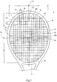
FIG. 1 is a front view of a tennis racket according to an embodiment of the present invention; -
FIG. 2 is a partially enlarged view of the tennis racket inFIG. 1 ; -
FIG. 3 is an enlarged view of an area surrounded by an alternate long and two short dashes line III inFIG. 2 ; -
FIG. 4 is an explanatory diagram for a testing method for the tennis racket inFIG. 1 ; -
FIG. 5 is a graph showing a relationship between a position from a top and an area ratio of each mesh in each of the tennis racket inFIG. 1 and a conventional tennis racket; and -
FIG. 6 is a graph showing a relationship between a position from the top and a resilience amount in each of the tennis racket inFIG. 1 and the conventional tennis racket. - The following will describe in detail the present invention based on preferred embodiments with appropriate reference to the drawings.
-
FIG. 1 shows atennis racket 2 according to the present invention. Thetennis racket 2 includes aracket frame 4, astring 6, ayoke 8, and agrip 10. Thetennis racket 2 is used for regulation-ball tennis. InFIG. 1 , the up-down direction is the longitudinal direction of thetennis racket 2, the right-left direction is the transverse direction of thetennis racket 2, and a direction perpendicular to the surface of the sheet is the thickness direction of thetennis racket 2. - The
racket frame 4 includes ahead 12, a pair ofthroats 14, and ashaft 16. Thehead 12, the pair ofthroats 14, and theshaft 16 are connected to each other. Thehead 12 extends in a curved manner so as to be bent back at the upper side. A pair of lower ends of thehead 12 are connected to each other via theyoke 8. In this manner, thehead 12 and theyoke 8 form anannular portion 18 having a substantially elliptical shape. - Each
throat 14 extends downward from the lower end of thehead 12. Thethroats 14 extend toward theshaft 16 in directions in which thethroats 14 come close to each other. Both end portions of theracket frame 4 extend downward further from the pair ofthroats 14. Both end portions are joined to each other. The joined end portions form theshaft 16. Thegrip 10 is formed at the outer side of theshaft 16. - The
string 6 is stretched on theannular portion 18 of theracket frame 4. Thestring 6 stretched on theannular portion 18 forms a plurality oflongitudinal strings 20 and a plurality oftransverse strings 22. Theselongitudinal strings 20 and thesetransverse strings 22 form a ball-hittingface 24. The ball-hittingface 24 has a substantially elliptical shape surrounded by theannular portion 18. The major axis direction of the ball-hittingface 24 is the longitudinal direction of thetennis racket 2. The minor axis direction of the ball-hittingface 24 is the transverse direction of thetennis racket 2. - In the
tennis racket 2, thestring 6 forms, for example, 16longitudinal strings 20, and, for example, 19transverse strings 22. Eachlongitudinal string 20 extends in the longitudinal direction inside theannular portion 18. Eachtransverse string 22 extends in the transverse direction inside theannular portion 18. Theselongitudinal strings 20 and thesetransverse strings 22 intersect each other to form a plurality ofmeshes 26. The shape of eachmesh 26 is a quadrangle surrounded by thelongitudinal strings 20 and thetransverse strings 22. -
FIG. 2 shows thelongitudinal strings 20 and thetransverse strings 22 stretched on theannular portion 18. InFIG. 2 , an alternate long and short dash line Ly represents a center line of the ball-hittingface 24 that extends in the longitudinal direction of thehead 12. The center line Ly extends through the center, in the transverse direction, of thehead 12. The center line Ly is also a straight line that passes through a position at which the dimension, in the longitudinal direction, of the ball-hittingface 24 is at its maximum. An alternate long and short dash line Lx represents a center line of the ball-hittingface 24 that extends in the transverse direction of thehead 12. InFIG. 2 , reference character P0 represents the center position of the ball-hittingface 24. The center position P0 represents the midpoint of a line segment extending on the ball-hittingface 24, of the center line Ly. The center line Lx is a straight line that passes through the center position P0 and extends in the transverse direction. - A point P1 represents the point of intersection of the annular portion 18 (head 12) and the center line Ly at the upper side. In the present invention, the point P1 is also referred to as a top of the
head 12. A point P2 represents the point of intersection of the annular portion 18 (yoke 8) and the center line Ly. A point P3 represents one point of intersection of the annular portion 18 (head 12) and the center line Lx in the transverse direction. A point P4 represents the other point of intersection of the annular portion 18 (head 12) and the center line Lx in the transverse direction. - In
FIG. 2 , a double-headed arrow x represents the interval between thelongitudinal strings 20 in the transverse direction. The interval x is measured as the interval between the axes of thelongitudinal strings 20 adjacent to each other in the transverse direction. A double-headed arrow y represents the interval between thetransverse strings 22 in the longitudinal direction. The interval y is measured as the interval between the axes of thetransverse strings 22 adjacent to each other in the longitudinal direction. Reference character S represents the area of a quadrangle formed by thelongitudinal strings 20 and thetransverse strings 22. The area S is obtained as the product of the interval x and the interval y. In the present invention, the area S is referred to as area of themesh 26. - In the present invention, the
mesh 26 in which the center position P0 is located, among a large number ofmeshes 26, is referred to as acenter mesh 26c. In addition, in the present invention, at the center in the transverse direction, themesh 26 that is closest to the top (point P1) of thehead 12 is referred to as atip mesh 26t. -
FIG. 3 shows an enlarged view of an area surrounded by an alternate long and two short dashes line III inFIG. 2 . InFIG. 3 , double-headed arrows y1 to y11 represent the magnitudes of the longitudinal intervals y at the respective meshes 26. The longitudinal intervals y are specified in order of y1 to y11 from the tip side toward the hand grip side. Although not shown, the longitudinal intervals y are further specified as y12, y13, and y14 from Y11 toward the hand grip side. In thetennis racket 2, the double-headed arrow y1 represents the longitudinal interval y at thetip mesh 26t. The double-headed arrow y9 represents the longitudinal interval y at thecenter mesh 26c. - In the
tennis racket 2, the longitudinal intervals y8 to y11 are set so as to have the same magnitude. The longitudinal interval y gradually increases from the longitudinal interval y8 toward the longitudinal interval y1. Similarly, the longitudinal interval y gradually increases from the longitudinal interval y11 toward the hand grip side. - In
FIG. 3 , each double-headed arrow x1 represents the magnitude of the transverse interval x between thelongitudinal strings 20. In thetennis racket 2, in the transverse direction, from one end to the other end thereof in the transverse direction, the transverse intervals x between thelongitudinal strings 20 are set so as to be uniform as a transverse interval x1. The transverse interval x at thecenter mesh 26c and the transverse interval x at thetip mesh 26t are also each set to a transverse interval x1. - In
FIG. 3 , reference characters S1 to S11 represent the areas S of the respective meshes 26. The areas S are specified in order of S1 to S11 from the tip side toward the hand grip side. Although not shown, the areas S are further specified as S12, S13, and S14 from S11 toward the hand grip side. In thetennis racket 2, the area S1 represents the area St of thetip mesh 26t. The area S9 represents the area Sc of thecenter mesh 26c. - In the
tennis racket 2, the areas S8, S9, S10, and S11 are set so as to have the same magnitude. In other words, the areas S8, S10, and S11 are set so as to have the same magnitude as the area Sc. Furthermore, the area S gradually increases from the area S8 toward the area St. Similarly, the area S gradually increases from the area S11 toward the hand grip side. -
FIG. 4 is an explanatory diagram for a testing method for resilience performance. The testing method for the resilience performance of thetennis racket 2 will be described with reference toFIG. 4 . - The
tennis racket 2 is placed on atest stand 28. The test stand 28 has aflat placement surface 30. Theplacement surface 30 is a flat surface that extends in the horizontal direction. Thehead 12 and theyoke 8 are placed on theplacement surface 30. Thetennis racket 2 is placed such that the ball-hittingface 24 is parallel to theplacement surface 30. In other words, thetennis racket 2 is placed such that thelongitudinal strings 20 and thetransverse strings 22 extend parallel to theplacement surface 30. Thetennis racket 2 is fixed to the test stand 28 by a cramp that is not shown. - In
FIG. 4 , reference character Pf represents a point located on the ball-hittingface 24. The point Pf is located on the straight line Ly. A double-headed arrow Y represents the distance from the top (point P1) of thehead 12 to the point Pf. The distance Y is measured along the ball-hittingface 24 in the longitudinal direction. - In the testing method for resilience performance, a tennis ball is caused to freely fall from a position having a predetermined height H from the ball-hitting
face 24 at the position of the distance Y. The tennis ball that has collided against the ball-hittingface 24 at the point Pf is rebounded. A resilience amount Hb of the rebounded tennis ball is measured. The resilience amount Hb is obtained as a maximum reach height of the tennis ball. The resilience amount Hb is obtained as a height from the ball-hittingface 24. The ratio (Hb/H) of the height Hb to the height H may be obtained. The ratio (Hb/H) is used as resilience performance. When the ratio (Hb/H) is greater, the resilience performance is higher. In this testing method, a tennis ball that complies with the ITF standards is used. In the testing method for resilience performance, the height H is set to 254 cm. The heights H and Hb are each measured as a distance from the ball-hittingface 24 to the lower position (lower end position) of the tennis ball. The heights H and Hb are each measured as a direct distance in the thickness direction of thetennis racket 2. -
FIG. 5 shows a graph of a relationship between a distance Y from the top and an area ratio (S/Sc) in each of thetennis racket 2 and a conventional tennis racket. InFIG. 5 , A is a graph of the area ratio (S/Sc) in thetennis racket 2, and B is a graph of the area ratio (S/Sc) in a commercially-available tennis racket as the conventional tennis racket. In thetennis racket 2, thecenter mesh 26c is located at a position at which the distance Y is 15 cm. Also in the conventional tennis racket, a center mesh is located at a position at which the distance Y is 15 cm. The ratio (S/Sc) is obtained as the ratio of the area S of themesh 26 located at the distance Y, relative to the area Sc of thecenter mesh 26c. - As shown in
FIG. 5 , in thetennis racket 2, the area ratio (S/Sc) increases as the position approaches the top from thecenter mesh 26c. The area ratio (S/Sc) in thetennis racket 2 is greater at the tip side than that in the conventional tennis racket. - A
mesh 26 having a large area S can bend more greatly when a tennis ball collides with thetennis racket 2, than amesh 26 having a small area S. The greater bending produces greater resilient force. In thetennis racket 2, resilience performance at the tip side is improved by increasing the area ratio (S/Sc). -
FIG. 6 shows a relationship between a distance Y from the top and a resilience amount.FIG. 6 is obtained through measurement by the testing method for resilience performance inFIG. 4 . InFIG. 6 , A is a graph of the resilience amount Hb of thetennis racket 2, and B is a graph of the resilience amount Hb of the commercially-available tennis racket. In thetennis racket 2, the resilience amount Hb increases from the lower side toward the upper side. - In the
tennis racket 2, a resilience amount Hb6 at a position at which the distance Y from the top is 6 cm, a resilience amount Hb9 at a position at which the distance Y from the top is 9 cm, and a resilience amount Hb12 at a position at which the distance Y from the top is 12 cm are each larger than a resilience amount Hb15 at the position at which the distance Y is 15 cm. In thetennis racket 2, the resilience amount Hb6, the resilience amount Hb9, and the resilience amount Hb12 at the tip side of the ball-hittingface 24 are larger than the resilience amount Hb15 at thecenter mesh 26c. On the other hand, in the conventional tennis racket, the resilience amount Hb decreases as the distance Y from the top decreases. - In the
tennis racket 2, the longitudinal interval y9 at thecenter mesh 26c is set so as to be less than the transverse interval x1 at thecenter mesh 26c. Although not shown, the magnitude of the longitudinal interval at the center mesh is generally set so as to be greater than that of the transverse interval at the center mesh in the conventional tennis racket. Accordingly, in thetennis racket 2, the ratio (St/Sc) of the area St at thetip mesh 26t to the area Sc at thecenter mesh 26c can be greater than that in the conventional tennis racket. - In the
tennis racket 2, the ratio (St/Sc) is increased and set so as to be not less than 1.6. In thetennis racket 2, the ratio (St/Sc) is greater than that in the conventional tennis racket. In thetennis racket 2 having a great ratio (St/Sc), high resilience performance is obtained at the vicinity of thetip mesh 26t. Thetennis racket 2 can strongly hit a ball at the vicinity of the tip portion. - The area S of the
mesh 26 preferably increases gradually from the center side toward the tip side. In other words, from thecenter mesh 26c to thetip mesh 26t, the area S of themesh 26 preferably increases gradually from the center toward the tip. Accordingly, a sudden change in resilience performance is inhibited. Thus, the resilience performance is made uniform from the center of the ball-hittingface 24 to the vicinity of the tip. - In the
tennis racket 2, the area Sc of thecenter mesh 26c, the area S8 of themesh 26 adjacent to thecenter mesh 26c at the tip side, the area S10 of themesh 26 adjacent to thecenter mesh 26c at the hand grip side, and the area S11 of themesh 26 adjacent to themesh 26 having the area S10 at the hand grip side are set so as to have the same magnitude. In the present invention, the area S does not necessarily have to gradually increase from thecenter mesh 26c to thetip mesh 26t. From the viewpoint of making the resilience uniform, the areas S ofmeshes 26 adjacent to each other in the longitudinal direction may be partially set so as to be equal to each other. Furthermore, from the viewpoint of obtaining high resilience at the tip side, the area St of thetip mesh 26t only needs to be larger than the area Sc of thecenter mesh 26c, and the area S of eachmesh 26 only needs to be not larger than the area S of themesh 26 adjacent thereto at the tip side. - The conventional tennis racket is configured such that the transverse interval x gradually increases from the center side toward the outer side in the transverse direction. In the
tennis racket 2, thelongitudinal strings 20 are stretched at equal intervals x1 from one end toward the other end in the transverse direction. In other words, the pitches between thelongitudinal strings 20 are constant. Accordingly, the area Sc of thecenter mesh 26c is inhibited from becoming extremely small even when the longitudinal interval y9 at thecenter mesh 26c is decreased. Amesh 26 having an excessively small area S decreases the resilience performance. In thetennis racket 2, even when the longitudinal interval y is decreased, since thelongitudinal strings 20 are stretched at equal intervals x1, the resilience performance is not greatly deteriorated. The tennis racket according to the present invention is not limited to a tennis racket in which the transverse intervals x between thelongitudinal strings 20 are equal. In the tennis racket, the transverse interval x may gradually increase or gradually decrease from the center side toward the outer side in the transverse direction. - From the viewpoint of inhibiting resilience performance from being deteriorated at the vicinity of the
center mesh 26c, the area Sc of thecenter mesh 26c is preferably not less than 70 mm2, further preferably not less than 90 mm2, and particularly preferably not less than 110 mm2. - Furthermore, uniform resilience performance is obtained from the center to the vicinity of the tip by decreasing the differences among the resilience amount Hb6, the resilience amount Hb9, the resilience amount Hb12, and the resilience amount Hb15. From the viewpoint of obtaining uniform resilience performance, among the resilience amount Hb6, the resilience amount Hb9, the resilience amount Hb12, and the resilience amount Hb15, the minimum resilience amount is preferably not less than 0.98 times of the maximum resilience amount.
- The
tennis racket 2 has excellent resilience performance at the tip side. Thetennis racket 2 is particularly suitable for modern swing. - From the viewpoint of increasing the resilience performance at the tip side, the present invention is particularly suitable for the
tennis racket 2 in which the longitudinal width of theannular portion 18 is larger than the transverse width thereof. - The
tennis racket 2 has a string pattern composed of 16longitudinal strings 20 and 19transverse strings 22, but the string pattern according to the present invention is not limited thereto. For example, the present invention can be similarly applied to a tennis racket having a string pattern composed of 16longitudinal strings transverse strings longitudinal strings transverse strings 22, or the like. The present invention is suitable in the case where the number oflongitudinal strings 20 is not less than 16 and not greater than 18 and the number oftransverse strings 22 is not less than 18 and not greater than 20. - The following will show the effects of the present invention by means of examples, but the present invention should not be construed in a limited manner based on the description of these examples.
- A tennis racket A shown in
FIG. 1 was prepared. The face size, the string pattern, the center position, and the area ratio (S/Sc) of each mesh to the center mesh of the tennis racket A were as shown in Table 1. The string pattern of the racket frame A was formed from 16 longitudinal strings and 19 transverse strings. In Table 1, M1 represents the first mesh from the tip side. In the tennis racket A, the first to eighteenth meshes were formed as M1 to M18 from the tip side toward the hand grip side. M9 at the center position represents that the ninth mesh from the tip side is the center mesh. - Tennis rackets B and C in each of which the face size, the string pattern, the center position, and the area ratio (S/Sc) of each mesh were as shown in Table 1 were prepared.
- Commercially-available tennis rackets D to M were prepared. The face sizes, the string patterns, the center positions, and the area ratios (S/Sc) of each mesh of these tennis rackets were as shown in Tables 1 and 2.
Table 1 Evaluation Results Ex. 1 Ex. 2 Ex. 3 Comp. Ex. 1 Comp. Ex. 2 Comp. Ex. 3 Comp. Ex. 4 Tennis racket A B C D E F G Face size 98 95 95 98 98 98 97 String pattern 16*19 16*19 18*20 16*19 16*19 16*19 16*20 Center position M9 M10 M11 M9 M10 M10 M12 Ratio S/Sc M1 1.83 1.77 1.71 1.52 1.48 1.11 1.27 M2 1.55 1.55 1.67 1.27 1.20 1.11 1.18 M3 1.40 1.40 1.55 1.23 1.08 1.04 1.14 M4 1.35 1.35 1.40 1.18 1.04 1.00 1.14 M5 1.30 1.30 1.30 1.18 1.00 1.00 1.14 M6 1.20 1.20 1.20 1.09 0.96 0.96 1.05 M7 1.10 1.10 1.10 1.09 1.00 0.96 1.05 M8 1.00 1.00 1.05 1.00 1.04 0.96 1.00 M9 1.00 1.00 1.05 1.00 1.04 1.00 1.00 M10 1.00 1.00 1.00 1.00 1.00 1.00 1.00 M11 1.00 1.00 1.00 1.00 1.00 1.00 1.00 M12 1.10 1.10 1.00 1.09 1.00 1.00 1.00 M13 1.25 1.15 1.05 1.09 1.00 1.04 1.05 M14 1.30 1.20 1.10 1.18 1.00 1.00 1.05 M15 1.45 1.25 1.15 1.27 1.00 1.04 1.14 M16 1.50 1.35 1.30 1.30 1.00 1.04 1.18 M17 1.60 1.40 1.50 1.41 1.12 1.15 1.32 M18 2.00 1.60 1.70 1.85 1.36 1.41 1.50 M19 - - 2.07 - - - 1.91 Table 2 Evaluation Results Comp. Ex. 5 Comp. Ex. 6 Comp. Ex. 7 Comp. Ex. 8 Comp. Ex. 9 Comp. Ex. 10 Tennis racket H I J K L M Face size 95 95 98 100 98 98 String pattern 16*19 16*19 16*19 16*18 16*20 16*19 Center position M9 M10 M10 M10 M10 M10 Ratio S/Sc M1 1.42 1.54 1.53 1.31 1.29 1.31 M2 1.21 1.23 1.51 1.31 1.13 1.11 M3 1.17 1.22 1.50 1.23 0.96 1.04 M4 1.08 1.18 1.41 1.23 0.96 1.00 M5 1.08 1.18 1.32 1.15 0.96 1.00 M6 1.00 1.09 1.23 1.12 0.92 0.96 M7 0.96 1.07 1.14 1.08 0.92 0.96 M8 0.96 1.00 1.05 1.04 0.96 0.96 M9 1.00 1.00 1.00 1.00 0.96 1.00 M10 1.00 1.00 1.00 1.00 1.00 1.00 M11 0.96 1.00 1.09 1.04 1.00 1.00 M12 1.00 1.09 1.18 1.08 1.00 1.00 M13 1.04 1.09 1.32 1.15 1.00 1.04 M14 1.00 1.16 1.45 1.27 1.08 1.00 M15 1.00 1.16 1.50 1.42 1.13 1.04 M16 1.04 1.25 1.55 1.56 1.25 1.04 M17 1.04 1.34 1.57 1.56 1.25 1.15 M18 1.38 1.48 1.65 - 1.33 1.41 M19 - - - - 1.58 - - In the tennis rackets of Examples 1 to 3, the ratios (St/Sc) of the tip mesh St to the center mesh Sc were 1.83, 1.77, and 1.71, respectively. On the other hand, in the tennis rackets of the Comparative Examples, the ratio (St/Sc) was at most 1.54. Also from this fact, it is obvious that, in the tennis racket according to the present invention, the ratio (S/Sc) is greater than that in the conventional tennis racket. From the viewpoint of exhibiting high resilience performance at the vicinity of the tip, the ratio (S/Sc) is preferably not less than 1.6 and further preferably not less than 1.7.
- The aforementioned tennis racket A of Example 1 was prepared. In addition, the tennis rackets D to H of Comparative Examples 1 to 5 were prepared as examples of conventional commercially-available products.
- These tennis rackets were evaluated for resilience performance by using the testing method for resilience performance in
FIG. 4 . In this testing method, the tension of the longitudinal strings was set to 50 (lbs), and the tension of the transverse strings was set to 45 (lbs). Three measurements were made for each tennis racket, and the average of measured values was obtained. The results are shown in Table 3. In each racket, among the resilience amount Hb6 at a distance Y of 6 cm, the resilience amount Hb9 at a distance Y of 9 cm, the resilience amount Hb12 at a distance Y of 12 cm, and the resilience amount Hb15 at a distance Y of 15 cm, with the maximum value being 1.00, the other resilience amounts are indicated as indexes.Table 3 Evaluation Results Ex. 1 Comp. Ex. 1 Comp. Ex. 2 Comp. Ex. 3 Comp. Ex. 4 Comp. Ex. 5 Tennis racket A D E F G H Resilience amount (cm) Y6 0.987 0.968 0.972 0.963 0.962 0.969 Y9 0.998 0.993 0.984 0.982 0.995 0.991 Y12 1.00 1.00 1.00 0.988 1.00 0.998 Y15 0.996 0.995 0.991 1.00 0.982 1.00 - As shown in Table 3, the tennis racket A of Example 1 has better resilience at the tip side than the conventional tennis rackets. In addition, the difference in resilience amount is decreased from the position at which the distance Y is 6 cm to the position at which the distance Y is 15 cm. Among the resilience amount Hb6, the resilience amount Hb9, the resilience amount Hb12, and the resilience amount Hb15, the minimum resilience amount Hb6 is not less than 0.98 times of the maximum resilience amount Hb12.
- A tennis racket N according to the present invention was prepared as Example 4. In the tennis racket N, the intervals between the longitudinal strings were made uniform, and the intervals between the transverse strings were small at the center side and gradually increased toward the outer side. In Table 4, M1, M3, M6, M9, M12, M15, and M18 each represent what number from the tip side the mesh is, similar to Table 1. In Table 4, the ratios (S/Sc) of the meshes of M1, M3, M6, M9, M12, M15, and M18 are shown.
- A tennis racket P of Comparative Example 11 was prepared as an example of a commercially-available product. In the tennis racket P, the intervals between the longitudinal strings and the intervals between the transverse strings were small at the center side and gradually increased toward the outer side. In Table 4, the ratios (S/Sc) of the meshes of M1, M3, M6, M9, M12, M15, and M18 of the tennis racket P are shown.
- Tennis rackets Q, R, and S were produced in the same manner as Example 1, except the intervals between the longitudinal strings, the intervals between the transverse strings, and the ratio (S/Sc) were as shown in Table 4. In the tennis racket Q, the shape of each mesh was a square.
- An advanced player made sensuous evaluation for these tennis rackets. The advanced player made evaluations for the size of the sweet area, the magnitude of vibration transmitted to the hand, and ease of providing spin, and made an overall evaluation. The results are shown in Table 4. The results are each indicated as a value with the value of Comparative Example 11 being a reference value 50. A higher value indicates a better result. The overall evaluation is represented as a value at five levels with the value of Comparative Example 11 being a
reference value 3. The higher the value is, the better the result is.Table 4 Evaluation Results Ex. 4 Comp. Ex. 11 Comp. Ex. 12 Comp. Ex. 13 Comp. Ex. 14 Tennis racket N P Q R S Longitudin al strings Uniform Sparse and dense Uniform Sparse and dense Sparse and dense Transverse strings Sparse and dense Sparse and dense Uniform Uniform Sparse and dense Ratio S/Sc M1 1.64 1.31 1.00 1.00 1.51 M3 1.38 1.18 1.00 1.00 1.38 M6 1.15 1.09 1.00 1.00 1.15 M9 1.00 1.00 1.00 1.00 1.00 M12 1.05 1.05 1.00 1.00 1.18 M15 1.38 1.23 1.00 1.00 1.38 M18 1.55 1.35 1.00 1.00 1.55 Sweet area 100 50 25 0 75 Vibration 100 50 0 0 75 Spin 100 50 0 33 0 Overall evaluation 5 3 1 2 3 - In the tennis racket N of Example 4, the area Sc of the center mesh was made relatively large while the ratio (St/Sc) was made great. Accordingly, the tennis racket N of Example 4 has excellent vibration absorption at a wide ball-hitting face from the vicinity of the center to the vicinity of the tip. The tennis racket N also has excellent ease of providing spin. The tennis racket N is highly rated as compared to the tennis rackets of the Comparative Examples. From the evaluation results, advantages of the present invention are clear.
- The method described above can be applied to a wide range of rackets for regulation-ball tennis.
- The above descriptions are merely illustrative examples, and various modifications can be made without departing from the principles of the present invention.
Claims (10)
- A tennis racket (2) in which longitudinal strings (20) extending in a longitudinal direction and transverse strings (22) extending in a transverse direction intersect each other to form a plurality of meshes (26), wherein
at a center, in the transverse direction, of a head (12), a ratio of an area St of a tip mesh (26t) located closest to a tip in the longitudinal direction relative to an area Sc of a center mesh (26c) located at a center (P0) in the longitudinal direction is not less than 1.6, and
the center mesh (26c) is formed in a rectangular shape having short sides (y9) in the longitudinal direction and long sides (x1) in the transverse direction. - The tennis racket (2) according to claim 1, wherein, from the center mesh (26c) to the tip mesh (26t), an area of each mesh (Sc-St) is set so as to be not larger than an area of a mesh adjacent thereto at a tip side.
- The tennis racket (2) according to claim 1 or 2, wherein, from the center mesh (26c) to the tip mesh (26t), the area of the mesh (Sc-St) gradually increases from the center (P0) toward the tip.
- The tennis racket (2) according to any one of claims 1 to 3, wherein pitches(x1) between the longitudinal strings (20) are constant in the transverse direction.
- The tennis racket (2) according to any one of the preceding claims, wherein
when resilience amounts (Hb) at positions at which a distance Y from a top of the head is 6 cm, 9 cm, 12 cm, and 15 cm are denoted by Hb6, Hb9, Hb12, and Hb15, respectively,
among the resilience amounts Hb6, Hb9, Hb12, and Hb15, a minimum resilience amount is not less than 0.98 times of a maximum resilience amount. - The tennis racket (2) according to any one of the preceding claims, wherein the area Sc of the center mesh is not less than 70 mm2.
- The tennis racket (2) according to any one of the preceding claims, wherein a number of the longitudinal strings (20) is not less than 16 and not greater than 18, and a number of the transverse strings (22) is not less than 18 and not greater than 20.
- The tennis racket (2) according to any one of the preceding claims, wherein the head (12) and a yoke (8) form an annular portion (18) having a substantially elliptical shape.
- The tennis racket (2) according to claim 8, wherein a longitudinal width of the annular portion (18) is larger than the transverse width thereof.
- The tennis racket (2) according to any one of the preceding claims, wherein, from the center mesh (26c) to a mesh at the hand grip side, an area of each mesh (St-S14) is set so as to be not larger than an area of a mesh adjacent thereto at a hand grip side.
Applications Claiming Priority (1)
| Application Number | Priority Date | Filing Date | Title |
|---|---|---|---|
| JP2018083991A JP7006485B2 (en) | 2018-04-25 | 2018-04-25 | tennis racket |
Publications (2)
| Publication Number | Publication Date |
|---|---|
| EP3560559A1 true EP3560559A1 (en) | 2019-10-30 |
| EP3560559B1 EP3560559B1 (en) | 2021-12-29 |
Family
ID=66001030
Family Applications (1)
| Application Number | Title | Priority Date | Filing Date |
|---|---|---|---|
| EP19165856.6A Active EP3560559B1 (en) | 2018-04-25 | 2019-03-28 | Tennis racket with different mesh size |
Country Status (4)
| Country | Link |
|---|---|
| US (1) | US10814188B2 (en) |
| EP (1) | EP3560559B1 (en) |
| JP (1) | JP7006485B2 (en) |
| CN (1) | CN110404238A (en) |
Cited By (1)
| Publication number | Priority date | Publication date | Assignee | Title |
|---|---|---|---|---|
| US20190329102A1 (en) * | 2018-04-25 | 2019-10-31 | Sumitomo Rubber Industries, Ltd. | Tennis racket |
Families Citing this family (3)
| Publication number | Priority date | Publication date | Assignee | Title |
|---|---|---|---|---|
| USD931964S1 (en) * | 2019-12-31 | 2021-09-28 | Head Technology Gmbh | Tennis racquet |
| USD931965S1 (en) * | 2019-12-31 | 2021-09-28 | Head Technology Gmbh | Tennis racquet |
| USD1004048S1 (en) * | 2022-05-10 | 2023-11-07 | Craig S. Blend | Fishing net frame |
Citations (8)
| Publication number | Priority date | Publication date | Assignee | Title |
|---|---|---|---|---|
| US3820785A (en) * | 1972-12-13 | 1974-06-28 | P Occhipinti | Practice tennis racket |
| GB2117253A (en) * | 1982-03-23 | 1983-10-12 | Jseng Kuni | Racquet |
| JPH07155409A (en) * | 1993-12-06 | 1995-06-20 | Sumitomo Rubber Ind Ltd | racket |
| JPH07178204A (en) * | 1993-12-21 | 1995-07-18 | Sumitomo Rubber Ind Ltd | racket |
| JP2002306639A (en) | 2001-04-18 | 2002-10-22 | Sumitomo Rubber Ind Ltd | racket |
| US20080102995A1 (en) * | 2006-10-25 | 2008-05-01 | Chia-Yuan Chang | Racket |
| US20170232308A1 (en) * | 2014-08-12 | 2017-08-17 | Babolat Vs | Tennis racket |
| JP2018083991A (en) | 2016-11-22 | 2018-05-31 | 株式会社タイキ | Silver glass-containing aqueous dispersion and textile processed with the aqueous dispersion |
Family Cites Families (12)
| Publication number | Priority date | Publication date | Assignee | Title |
|---|---|---|---|---|
| US1173712A (en) * | 1916-02-29 | Harry D Du Bois | Tennis-racket. | |
| GB225934A (en) * | 1923-09-12 | 1924-12-12 | Robert Rose | Improvements in tennis racquets and the like |
| US4013289A (en) * | 1975-06-30 | 1977-03-22 | Bernard Kaminstein | Tennis racket |
| US4231575A (en) * | 1977-12-23 | 1980-11-04 | Mers Kutt | Racket stringing |
| US4330125A (en) * | 1980-08-22 | 1982-05-18 | Sassler Marvin L | Apparatus for reducing torque and vibration in racquets |
| US4512575A (en) * | 1982-11-30 | 1985-04-23 | Tzeng Kuo Nan | Racquet having strings of equal length |
| GB9120585D0 (en) * | 1991-09-27 | 1991-11-06 | Dunlop Ltd | Games racket frame |
| US5779573A (en) * | 1997-05-16 | 1998-07-14 | You; Chin-San | Game Racket |
| US20060084532A1 (en) * | 2004-10-20 | 2006-04-20 | Chaokang Chu | Strings for racquets |
| JP2013255583A (en) * | 2012-06-11 | 2013-12-26 | Mizuno Corp | Racket and racket frame |
| US9089743B2 (en) * | 2012-07-24 | 2015-07-28 | Wilson Sporting Goods Co. | Racquet configured with fewer cross strings than main strings |
| JP7006485B2 (en) * | 2018-04-25 | 2022-02-10 | 住友ゴム工業株式会社 | tennis racket |
-
2018
- 2018-04-25 JP JP2018083991A patent/JP7006485B2/en active Active
-
2019
- 2019-03-15 CN CN201910199205.XA patent/CN110404238A/en active Pending
- 2019-03-28 EP EP19165856.6A patent/EP3560559B1/en active Active
- 2019-04-09 US US16/378,655 patent/US10814188B2/en active Active
Patent Citations (8)
| Publication number | Priority date | Publication date | Assignee | Title |
|---|---|---|---|---|
| US3820785A (en) * | 1972-12-13 | 1974-06-28 | P Occhipinti | Practice tennis racket |
| GB2117253A (en) * | 1982-03-23 | 1983-10-12 | Jseng Kuni | Racquet |
| JPH07155409A (en) * | 1993-12-06 | 1995-06-20 | Sumitomo Rubber Ind Ltd | racket |
| JPH07178204A (en) * | 1993-12-21 | 1995-07-18 | Sumitomo Rubber Ind Ltd | racket |
| JP2002306639A (en) | 2001-04-18 | 2002-10-22 | Sumitomo Rubber Ind Ltd | racket |
| US20080102995A1 (en) * | 2006-10-25 | 2008-05-01 | Chia-Yuan Chang | Racket |
| US20170232308A1 (en) * | 2014-08-12 | 2017-08-17 | Babolat Vs | Tennis racket |
| JP2018083991A (en) | 2016-11-22 | 2018-05-31 | 株式会社タイキ | Silver glass-containing aqueous dispersion and textile processed with the aqueous dispersion |
Cited By (2)
| Publication number | Priority date | Publication date | Assignee | Title |
|---|---|---|---|---|
| US20190329102A1 (en) * | 2018-04-25 | 2019-10-31 | Sumitomo Rubber Industries, Ltd. | Tennis racket |
| US10814188B2 (en) * | 2018-04-25 | 2020-10-27 | Sumitomo Rubber Industries, Ltd. | Tennis racket |
Also Published As
| Publication number | Publication date |
|---|---|
| JP7006485B2 (en) | 2022-02-10 |
| JP2019187784A (en) | 2019-10-31 |
| CN110404238A (en) | 2019-11-05 |
| EP3560559B1 (en) | 2021-12-29 |
| US20190329102A1 (en) | 2019-10-31 |
| US10814188B2 (en) | 2020-10-27 |
Similar Documents
| Publication | Publication Date | Title |
|---|---|---|
| EP3560559B1 (en) | Tennis racket with different mesh size | |
| US4720111A (en) | Golf ball | |
| US9566481B2 (en) | Striking face of a golf club head | |
| US9333400B2 (en) | Golf club set providing improved distance gapping adjustability | |
| US20160144246A1 (en) | Golf club head | |
| US7442130B2 (en) | Iron set | |
| EP4176941B1 (en) | Racket | |
| JPH1147317A (en) | Golf club head having face groove | |
| JP4306912B2 (en) | Golf club set | |
| JP2002165909A (en) | Golf club head | |
| JP2840556B2 (en) | Golf club set | |
| US10286264B2 (en) | Golf club set with progression of curvature of sole and center of gravity | |
| KR20160090205A (en) | Head part of putter for golf and putter for golf using the same | |
| US20010041625A1 (en) | Iron golf club set | |
| JP7168502B2 (en) | Wood type golf club set | |
| JP2726230B2 (en) | racket | |
| US10272305B2 (en) | Golf club set | |
| JPH07213653A (en) | racket | |
| JP2002306643A (en) | Golf club set | |
| JPH1033719A (en) | racket | |
| JP3013790B2 (en) | Arrangement method of dimples in golf ball | |
| JPH0748282Y2 (en) | Golf club set | |
| JP4733353B2 (en) | Golf club set | |
| JP2001252378A (en) | Driver club head | |
| JPH06292743A (en) | Tennis racket frame |
Legal Events
| Date | Code | Title | Description |
|---|---|---|---|
| PUAI | Public reference made under article 153(3) epc to a published international application that has entered the european phase |
Free format text: ORIGINAL CODE: 0009012 |
|
| STAA | Information on the status of an ep patent application or granted ep patent |
Free format text: STATUS: THE APPLICATION HAS BEEN PUBLISHED |
|
| AK | Designated contracting states |
Kind code of ref document: A1 Designated state(s): AL AT BE BG CH CY CZ DE DK EE ES FI FR GB GR HR HU IE IS IT LI LT LU LV MC MK MT NL NO PL PT RO RS SE SI SK SM TR |
|
| AX | Request for extension of the european patent |
Extension state: BA ME |
|
| STAA | Information on the status of an ep patent application or granted ep patent |
Free format text: STATUS: REQUEST FOR EXAMINATION WAS MADE |
|
| 17P | Request for examination filed |
Effective date: 20200330 |
|
| RBV | Designated contracting states (corrected) |
Designated state(s): AL AT BE BG CH CY CZ DE DK EE ES FI FR GB GR HR HU IE IS IT LI LT LU LV MC MK MT NL NO PL PT RO RS SE SI SK SM TR |
|
| GRAP | Despatch of communication of intention to grant a patent |
Free format text: ORIGINAL CODE: EPIDOSNIGR1 |
|
| STAA | Information on the status of an ep patent application or granted ep patent |
Free format text: STATUS: GRANT OF PATENT IS INTENDED |
|
| INTG | Intention to grant announced |
Effective date: 20210818 |
|
| RAP3 | Party data changed (applicant data changed or rights of an application transferred) |
Owner name: SUMITOMO RUBBER INDUSTRIES, LTD. |
|
| GRAS | Grant fee paid |
Free format text: ORIGINAL CODE: EPIDOSNIGR3 |
|
| GRAA | (expected) grant |
Free format text: ORIGINAL CODE: 0009210 |
|
| STAA | Information on the status of an ep patent application or granted ep patent |
Free format text: STATUS: THE PATENT HAS BEEN GRANTED |
|
| AK | Designated contracting states |
Kind code of ref document: B1 Designated state(s): AL AT BE BG CH CY CZ DE DK EE ES FI FR GB GR HR HU IE IS IT LI LT LU LV MC MK MT NL NO PL PT RO RS SE SI SK SM TR |
|
| REG | Reference to a national code |
Ref country code: GB Ref legal event code: FG4D |
|
| REG | Reference to a national code |
Ref country code: CH Ref legal event code: EP |
|
| REG | Reference to a national code |
Ref country code: AT Ref legal event code: REF Ref document number: 1458241 Country of ref document: AT Kind code of ref document: T Effective date: 20220115 |
|
| REG | Reference to a national code |
Ref country code: IE Ref legal event code: FG4D |
|
| REG | Reference to a national code |
Ref country code: DE Ref legal event code: R096 Ref document number: 602019010363 Country of ref document: DE |
|
| REG | Reference to a national code |
Ref country code: LT Ref legal event code: MG9D |
|
| PG25 | Lapsed in a contracting state [announced via postgrant information from national office to epo] |
Ref country code: RS Free format text: LAPSE BECAUSE OF FAILURE TO SUBMIT A TRANSLATION OF THE DESCRIPTION OR TO PAY THE FEE WITHIN THE PRESCRIBED TIME-LIMIT Effective date: 20211229 Ref country code: LT Free format text: LAPSE BECAUSE OF FAILURE TO SUBMIT A TRANSLATION OF THE DESCRIPTION OR TO PAY THE FEE WITHIN THE PRESCRIBED TIME-LIMIT Effective date: 20211229 Ref country code: FI Free format text: LAPSE BECAUSE OF FAILURE TO SUBMIT A TRANSLATION OF THE DESCRIPTION OR TO PAY THE FEE WITHIN THE PRESCRIBED TIME-LIMIT Effective date: 20211229 Ref country code: BG Free format text: LAPSE BECAUSE OF FAILURE TO SUBMIT A TRANSLATION OF THE DESCRIPTION OR TO PAY THE FEE WITHIN THE PRESCRIBED TIME-LIMIT Effective date: 20220329 |
|
| REG | Reference to a national code |
Ref country code: NL Ref legal event code: MP Effective date: 20211229 |
|
| REG | Reference to a national code |
Ref country code: AT Ref legal event code: MK05 Ref document number: 1458241 Country of ref document: AT Kind code of ref document: T Effective date: 20211229 |
|
| PG25 | Lapsed in a contracting state [announced via postgrant information from national office to epo] |
Ref country code: SE Free format text: LAPSE BECAUSE OF FAILURE TO SUBMIT A TRANSLATION OF THE DESCRIPTION OR TO PAY THE FEE WITHIN THE PRESCRIBED TIME-LIMIT Effective date: 20211229 Ref country code: NO Free format text: LAPSE BECAUSE OF FAILURE TO SUBMIT A TRANSLATION OF THE DESCRIPTION OR TO PAY THE FEE WITHIN THE PRESCRIBED TIME-LIMIT Effective date: 20220329 Ref country code: LV Free format text: LAPSE BECAUSE OF FAILURE TO SUBMIT A TRANSLATION OF THE DESCRIPTION OR TO PAY THE FEE WITHIN THE PRESCRIBED TIME-LIMIT Effective date: 20211229 Ref country code: HR Free format text: LAPSE BECAUSE OF FAILURE TO SUBMIT A TRANSLATION OF THE DESCRIPTION OR TO PAY THE FEE WITHIN THE PRESCRIBED TIME-LIMIT Effective date: 20211229 Ref country code: GR Free format text: LAPSE BECAUSE OF FAILURE TO SUBMIT A TRANSLATION OF THE DESCRIPTION OR TO PAY THE FEE WITHIN THE PRESCRIBED TIME-LIMIT Effective date: 20220330 |
|
| PG25 | Lapsed in a contracting state [announced via postgrant information from national office to epo] |
Ref country code: NL Free format text: LAPSE BECAUSE OF FAILURE TO SUBMIT A TRANSLATION OF THE DESCRIPTION OR TO PAY THE FEE WITHIN THE PRESCRIBED TIME-LIMIT Effective date: 20211229 |
|
| PG25 | Lapsed in a contracting state [announced via postgrant information from national office to epo] |
Ref country code: SM Free format text: LAPSE BECAUSE OF FAILURE TO SUBMIT A TRANSLATION OF THE DESCRIPTION OR TO PAY THE FEE WITHIN THE PRESCRIBED TIME-LIMIT Effective date: 20211229 Ref country code: SK Free format text: LAPSE BECAUSE OF FAILURE TO SUBMIT A TRANSLATION OF THE DESCRIPTION OR TO PAY THE FEE WITHIN THE PRESCRIBED TIME-LIMIT Effective date: 20211229 Ref country code: RO Free format text: LAPSE BECAUSE OF FAILURE TO SUBMIT A TRANSLATION OF THE DESCRIPTION OR TO PAY THE FEE WITHIN THE PRESCRIBED TIME-LIMIT Effective date: 20211229 Ref country code: PT Free format text: LAPSE BECAUSE OF FAILURE TO SUBMIT A TRANSLATION OF THE DESCRIPTION OR TO PAY THE FEE WITHIN THE PRESCRIBED TIME-LIMIT Effective date: 20220429 Ref country code: ES Free format text: LAPSE BECAUSE OF FAILURE TO SUBMIT A TRANSLATION OF THE DESCRIPTION OR TO PAY THE FEE WITHIN THE PRESCRIBED TIME-LIMIT Effective date: 20211229 Ref country code: EE Free format text: LAPSE BECAUSE OF FAILURE TO SUBMIT A TRANSLATION OF THE DESCRIPTION OR TO PAY THE FEE WITHIN THE PRESCRIBED TIME-LIMIT Effective date: 20211229 Ref country code: CZ Free format text: LAPSE BECAUSE OF FAILURE TO SUBMIT A TRANSLATION OF THE DESCRIPTION OR TO PAY THE FEE WITHIN THE PRESCRIBED TIME-LIMIT Effective date: 20211229 |
|
| PG25 | Lapsed in a contracting state [announced via postgrant information from national office to epo] |
Ref country code: PL Free format text: LAPSE BECAUSE OF FAILURE TO SUBMIT A TRANSLATION OF THE DESCRIPTION OR TO PAY THE FEE WITHIN THE PRESCRIBED TIME-LIMIT Effective date: 20211229 Ref country code: AT Free format text: LAPSE BECAUSE OF FAILURE TO SUBMIT A TRANSLATION OF THE DESCRIPTION OR TO PAY THE FEE WITHIN THE PRESCRIBED TIME-LIMIT Effective date: 20211229 |
|
| PG25 | Lapsed in a contracting state [announced via postgrant information from national office to epo] |
Ref country code: IS Free format text: LAPSE BECAUSE OF FAILURE TO SUBMIT A TRANSLATION OF THE DESCRIPTION OR TO PAY THE FEE WITHIN THE PRESCRIBED TIME-LIMIT Effective date: 20220429 |
|
| REG | Reference to a national code |
Ref country code: DE Ref legal event code: R097 Ref document number: 602019010363 Country of ref document: DE |
|
| PG25 | Lapsed in a contracting state [announced via postgrant information from national office to epo] |
Ref country code: MC Free format text: LAPSE BECAUSE OF FAILURE TO SUBMIT A TRANSLATION OF THE DESCRIPTION OR TO PAY THE FEE WITHIN THE PRESCRIBED TIME-LIMIT Effective date: 20211229 Ref country code: DK Free format text: LAPSE BECAUSE OF FAILURE TO SUBMIT A TRANSLATION OF THE DESCRIPTION OR TO PAY THE FEE WITHIN THE PRESCRIBED TIME-LIMIT Effective date: 20211229 Ref country code: AL Free format text: LAPSE BECAUSE OF FAILURE TO SUBMIT A TRANSLATION OF THE DESCRIPTION OR TO PAY THE FEE WITHIN THE PRESCRIBED TIME-LIMIT Effective date: 20211229 |
|
| REG | Reference to a national code |
Ref country code: CH Ref legal event code: PL |
|
| PLBE | No opposition filed within time limit |
Free format text: ORIGINAL CODE: 0009261 |
|
| STAA | Information on the status of an ep patent application or granted ep patent |
Free format text: STATUS: NO OPPOSITION FILED WITHIN TIME LIMIT |
|
| 26N | No opposition filed |
Effective date: 20220930 |
|
| REG | Reference to a national code |
Ref country code: BE Ref legal event code: MM Effective date: 20220331 |
|
| PG25 | Lapsed in a contracting state [announced via postgrant information from national office to epo] |
Ref country code: LU Free format text: LAPSE BECAUSE OF NON-PAYMENT OF DUE FEES Effective date: 20220328 Ref country code: LI Free format text: LAPSE BECAUSE OF NON-PAYMENT OF DUE FEES Effective date: 20220331 Ref country code: IE Free format text: LAPSE BECAUSE OF NON-PAYMENT OF DUE FEES Effective date: 20220328 Ref country code: CH Free format text: LAPSE BECAUSE OF NON-PAYMENT OF DUE FEES Effective date: 20220331 |
|
| PG25 | Lapsed in a contracting state [announced via postgrant information from national office to epo] |
Ref country code: SI Free format text: LAPSE BECAUSE OF FAILURE TO SUBMIT A TRANSLATION OF THE DESCRIPTION OR TO PAY THE FEE WITHIN THE PRESCRIBED TIME-LIMIT Effective date: 20211229 Ref country code: BE Free format text: LAPSE BECAUSE OF NON-PAYMENT OF DUE FEES Effective date: 20220331 |
|
| PG25 | Lapsed in a contracting state [announced via postgrant information from national office to epo] |
Ref country code: IT Free format text: LAPSE BECAUSE OF FAILURE TO SUBMIT A TRANSLATION OF THE DESCRIPTION OR TO PAY THE FEE WITHIN THE PRESCRIBED TIME-LIMIT Effective date: 20211229 |
|
| P01 | Opt-out of the competence of the unified patent court (upc) registered |
Effective date: 20230510 |
|
| PG25 | Lapsed in a contracting state [announced via postgrant information from national office to epo] |
Ref country code: MK Free format text: LAPSE BECAUSE OF FAILURE TO SUBMIT A TRANSLATION OF THE DESCRIPTION OR TO PAY THE FEE WITHIN THE PRESCRIBED TIME-LIMIT Effective date: 20211229 Ref country code: CY Free format text: LAPSE BECAUSE OF FAILURE TO SUBMIT A TRANSLATION OF THE DESCRIPTION OR TO PAY THE FEE WITHIN THE PRESCRIBED TIME-LIMIT Effective date: 20211229 |
|
| PG25 | Lapsed in a contracting state [announced via postgrant information from national office to epo] |
Ref country code: HU Free format text: LAPSE BECAUSE OF FAILURE TO SUBMIT A TRANSLATION OF THE DESCRIPTION OR TO PAY THE FEE WITHIN THE PRESCRIBED TIME-LIMIT; INVALID AB INITIO Effective date: 20190328 |
|
| PG25 | Lapsed in a contracting state [announced via postgrant information from national office to epo] |
Ref country code: TR Free format text: LAPSE BECAUSE OF FAILURE TO SUBMIT A TRANSLATION OF THE DESCRIPTION OR TO PAY THE FEE WITHIN THE PRESCRIBED TIME-LIMIT Effective date: 20211229 |
|
| PG25 | Lapsed in a contracting state [announced via postgrant information from national office to epo] |
Ref country code: MT Free format text: LAPSE BECAUSE OF FAILURE TO SUBMIT A TRANSLATION OF THE DESCRIPTION OR TO PAY THE FEE WITHIN THE PRESCRIBED TIME-LIMIT Effective date: 20211229 |
|
| PGFP | Annual fee paid to national office [announced via postgrant information from national office to epo] |
Ref country code: GB Payment date: 20260209 Year of fee payment: 8 |
|
| PGFP | Annual fee paid to national office [announced via postgrant information from national office to epo] |
Ref country code: DE Payment date: 20260204 Year of fee payment: 8 |
|
| PGFP | Annual fee paid to national office [announced via postgrant information from national office to epo] |
Ref country code: FR Payment date: 20260209 Year of fee payment: 8 |