EP3560469A1 - Saugfähiger artikel - Google Patents
Saugfähiger artikel Download PDFInfo
- Publication number
- EP3560469A1 EP3560469A1 EP18168885.4A EP18168885A EP3560469A1 EP 3560469 A1 EP3560469 A1 EP 3560469A1 EP 18168885 A EP18168885 A EP 18168885A EP 3560469 A1 EP3560469 A1 EP 3560469A1
- Authority
- EP
- European Patent Office
- Prior art keywords
- absorbent
- management structure
- liquid
- liquid management
- attachment zone
- Prior art date
- Legal status (The legal status is an assumption and is not a legal conclusion. Google has not performed a legal analysis and makes no representation as to the accuracy of the status listed.)
- Granted
Links
- 239000002250 absorbent Substances 0.000 title claims abstract description 393
- 230000002745 absorbent Effects 0.000 title claims abstract description 393
- 239000007788 liquid Substances 0.000 claims abstract description 272
- 239000000463 material Substances 0.000 claims abstract description 164
- 238000009826 distribution Methods 0.000 claims description 30
- 238000009736 wetting Methods 0.000 claims description 13
- 239000002245 particle Substances 0.000 claims description 10
- 230000009471 action Effects 0.000 claims description 6
- 238000007789 sealing Methods 0.000 claims description 3
- 239000011162 core material Substances 0.000 description 197
- 238000007726 management method Methods 0.000 description 140
- 239000000835 fiber Substances 0.000 description 43
- 239000010410 layer Substances 0.000 description 43
- 238000000034 method Methods 0.000 description 21
- 238000004519 manufacturing process Methods 0.000 description 15
- 239000002861 polymer material Substances 0.000 description 13
- 238000010521 absorption reaction Methods 0.000 description 12
- 239000000853 adhesive Substances 0.000 description 12
- 230000001070 adhesive effect Effects 0.000 description 12
- 206010021639 Incontinence Diseases 0.000 description 10
- 239000000306 component Substances 0.000 description 10
- 210000000416 exudates and transudate Anatomy 0.000 description 10
- 239000000126 substance Substances 0.000 description 9
- 229920003043 Cellulose fiber Polymers 0.000 description 8
- 239000006185 dispersion Substances 0.000 description 8
- 239000012530 fluid Substances 0.000 description 7
- 239000002994 raw material Substances 0.000 description 7
- XLYOFNOQVPJJNP-UHFFFAOYSA-N water Substances O XLYOFNOQVPJJNP-UHFFFAOYSA-N 0.000 description 7
- 239000004744 fabric Substances 0.000 description 6
- 230000008569 process Effects 0.000 description 6
- 229920002678 cellulose Polymers 0.000 description 5
- 239000001913 cellulose Substances 0.000 description 5
- 239000004745 nonwoven fabric Substances 0.000 description 5
- 229920000642 polymer Polymers 0.000 description 5
- 230000015572 biosynthetic process Effects 0.000 description 4
- 210000002414 leg Anatomy 0.000 description 4
- 230000014759 maintenance of location Effects 0.000 description 4
- 239000011236 particulate material Substances 0.000 description 4
- 239000002904 solvent Substances 0.000 description 4
- 239000000758 substrate Substances 0.000 description 4
- 210000002700 urine Anatomy 0.000 description 4
- 229920001131 Pulp (paper) Polymers 0.000 description 3
- 229920000297 Rayon Polymers 0.000 description 3
- 239000000470 constituent Substances 0.000 description 3
- 230000009969 flowable effect Effects 0.000 description 3
- 239000000203 mixture Substances 0.000 description 3
- 239000011347 resin Substances 0.000 description 3
- 229920005989 resin Polymers 0.000 description 3
- 229920001169 thermoplastic Polymers 0.000 description 3
- 239000004416 thermosoftening plastic Substances 0.000 description 3
- 230000007704 transition Effects 0.000 description 3
- 229920000742 Cotton Polymers 0.000 description 2
- 230000001464 adherent effect Effects 0.000 description 2
- 230000004888 barrier function Effects 0.000 description 2
- 239000011230 binding agent Substances 0.000 description 2
- 239000008280 blood Substances 0.000 description 2
- 210000004369 blood Anatomy 0.000 description 2
- 210000001124 body fluid Anatomy 0.000 description 2
- 239000002131 composite material Substances 0.000 description 2
- 150000001875 compounds Chemical class 0.000 description 2
- 238000004132 cross linking Methods 0.000 description 2
- 238000000151 deposition Methods 0.000 description 2
- 238000013461 design Methods 0.000 description 2
- 239000002657 fibrous material Substances 0.000 description 2
- 239000010408 film Substances 0.000 description 2
- 239000006260 foam Substances 0.000 description 2
- 239000003292 glue Substances 0.000 description 2
- 238000010438 heat treatment Methods 0.000 description 2
- 229910052500 inorganic mineral Inorganic materials 0.000 description 2
- 238000005304 joining Methods 0.000 description 2
- 239000004750 melt-blown nonwoven Substances 0.000 description 2
- 238000002844 melting Methods 0.000 description 2
- 230000008018 melting Effects 0.000 description 2
- 239000011707 mineral Substances 0.000 description 2
- 239000004033 plastic Substances 0.000 description 2
- 229920003023 plastic Polymers 0.000 description 2
- -1 polypropylene Polymers 0.000 description 2
- 239000000843 powder Substances 0.000 description 2
- 239000002964 rayon Substances 0.000 description 2
- 239000007787 solid Substances 0.000 description 2
- 239000004753 textile Substances 0.000 description 2
- 238000009941 weaving Methods 0.000 description 2
- QTBSBXVTEAMEQO-UHFFFAOYSA-M Acetate Chemical compound CC([O-])=O QTBSBXVTEAMEQO-UHFFFAOYSA-M 0.000 description 1
- 229920002284 Cellulose triacetate Polymers 0.000 description 1
- 240000000491 Corchorus aestuans Species 0.000 description 1
- 235000011777 Corchorus aestuans Nutrition 0.000 description 1
- 235000010862 Corchorus capsularis Nutrition 0.000 description 1
- 241000219146 Gossypium Species 0.000 description 1
- 239000004831 Hot glue Substances 0.000 description 1
- 240000006240 Linum usitatissimum Species 0.000 description 1
- 235000004431 Linum usitatissimum Nutrition 0.000 description 1
- 239000004677 Nylon Substances 0.000 description 1
- 239000004743 Polypropylene Substances 0.000 description 1
- 239000004820 Pressure-sensitive adhesive Substances 0.000 description 1
- FAPWRFPIFSIZLT-UHFFFAOYSA-M Sodium chloride Chemical compound [Na+].[Cl-] FAPWRFPIFSIZLT-UHFFFAOYSA-M 0.000 description 1
- 239000011358 absorbing material Substances 0.000 description 1
- NIXOWILDQLNWCW-UHFFFAOYSA-N acrylic acid group Chemical group C(C=C)(=O)O NIXOWILDQLNWCW-UHFFFAOYSA-N 0.000 description 1
- 238000004026 adhesive bonding Methods 0.000 description 1
- 239000002390 adhesive tape Substances 0.000 description 1
- 238000005054 agglomeration Methods 0.000 description 1
- 230000002776 aggregation Effects 0.000 description 1
- 229920005603 alternating copolymer Polymers 0.000 description 1
- 239000010425 asbestos Substances 0.000 description 1
- 239000012298 atmosphere Substances 0.000 description 1
- 229920001400 block copolymer Polymers 0.000 description 1
- 238000007664 blowing Methods 0.000 description 1
- 239000010839 body fluid Substances 0.000 description 1
- 210000001217 buttock Anatomy 0.000 description 1
- 238000009960 carding Methods 0.000 description 1
- 229920002301 cellulose acetate Polymers 0.000 description 1
- 210000003756 cervix mucus Anatomy 0.000 description 1
- 238000006243 chemical reaction Methods 0.000 description 1
- 239000003795 chemical substances by application Substances 0.000 description 1
- 239000011248 coating agent Substances 0.000 description 1
- 238000000576 coating method Methods 0.000 description 1
- 238000004891 communication Methods 0.000 description 1
- 230000003750 conditioning effect Effects 0.000 description 1
- 238000001816 cooling Methods 0.000 description 1
- 229920001577 copolymer Polymers 0.000 description 1
- 239000008358 core component Substances 0.000 description 1
- 239000012792 core layer Substances 0.000 description 1
- 238000001035 drying Methods 0.000 description 1
- 238000001523 electrospinning Methods 0.000 description 1
- 239000000839 emulsion Substances 0.000 description 1
- 238000005265 energy consumption Methods 0.000 description 1
- 210000003608 fece Anatomy 0.000 description 1
- 239000011521 glass Substances 0.000 description 1
- 229920000578 graft copolymer Polymers 0.000 description 1
- 239000008187 granular material Substances 0.000 description 1
- 229920001519 homopolymer Polymers 0.000 description 1
- 239000012943 hotmelt Substances 0.000 description 1
- 210000004251 human milk Anatomy 0.000 description 1
- 235000020256 human milk Nutrition 0.000 description 1
- 230000002209 hydrophobic effect Effects 0.000 description 1
- 238000007654 immersion Methods 0.000 description 1
- 238000005470 impregnation Methods 0.000 description 1
- 238000011065 in-situ storage Methods 0.000 description 1
- 238000003780 insertion Methods 0.000 description 1
- 230000037431 insertion Effects 0.000 description 1
- 238000009940 knitting Methods 0.000 description 1
- 239000000155 melt Substances 0.000 description 1
- 238000012986 modification Methods 0.000 description 1
- 230000004048 modification Effects 0.000 description 1
- 239000003607 modifier Substances 0.000 description 1
- 229920005615 natural polymer Polymers 0.000 description 1
- 229920001778 nylon Polymers 0.000 description 1
- 230000003204 osmotic effect Effects 0.000 description 1
- 238000004806 packaging method and process Methods 0.000 description 1
- 229920000728 polyester Polymers 0.000 description 1
- 229920001155 polypropylene Polymers 0.000 description 1
- 238000007639 printing Methods 0.000 description 1
- 229920005604 random copolymer Polymers 0.000 description 1
- 239000004627 regenerated cellulose Substances 0.000 description 1
- 229910052895 riebeckite Inorganic materials 0.000 description 1
- 239000012945 sealing adhesive Substances 0.000 description 1
- 239000011343 solid material Substances 0.000 description 1
- 239000000243 solution Substances 0.000 description 1
- 238000001179 sorption measurement Methods 0.000 description 1
- 238000009987 spinning Methods 0.000 description 1
- 238000005507 spraying Methods 0.000 description 1
- 239000003351 stiffener Substances 0.000 description 1
- 238000003860 storage Methods 0.000 description 1
- 229920000247 superabsorbent polymer Polymers 0.000 description 1
- 210000004243 sweat Anatomy 0.000 description 1
- 230000002123 temporal effect Effects 0.000 description 1
- 229920001897 terpolymer Polymers 0.000 description 1
- 238000012360 testing method Methods 0.000 description 1
- 239000012815 thermoplastic material Substances 0.000 description 1
- 238000012549 training Methods 0.000 description 1
- 238000012384 transportation and delivery Methods 0.000 description 1
- ILJSQTXMGCGYMG-UHFFFAOYSA-N triacetic acid Chemical compound CC(=O)CC(=O)CC(O)=O ILJSQTXMGCGYMG-UHFFFAOYSA-N 0.000 description 1
- 206010046901 vaginal discharge Diseases 0.000 description 1
- 235000013311 vegetables Nutrition 0.000 description 1
- 238000001238 wet grinding Methods 0.000 description 1
- 210000002268 wool Anatomy 0.000 description 1
Images


Classifications
-
- A—HUMAN NECESSITIES
- A61—MEDICAL OR VETERINARY SCIENCE; HYGIENE
- A61F—FILTERS IMPLANTABLE INTO BLOOD VESSELS; PROSTHESES; DEVICES PROVIDING PATENCY TO, OR PREVENTING COLLAPSING OF, TUBULAR STRUCTURES OF THE BODY, e.g. STENTS; ORTHOPAEDIC, NURSING OR CONTRACEPTIVE DEVICES; FOMENTATION; TREATMENT OR PROTECTION OF EYES OR EARS; BANDAGES, DRESSINGS OR ABSORBENT PADS; FIRST-AID KITS
- A61F13/00—Bandages or dressings; Absorbent pads
- A61F13/15—Absorbent pads, e.g. sanitary towels, swabs or tampons for external or internal application to the body; Supporting or fastening means therefor; Tampon applicators
- A61F13/53—Absorbent pads, e.g. sanitary towels, swabs or tampons for external or internal application to the body; Supporting or fastening means therefor; Tampon applicators characterised by the absorbing medium
- A61F13/531—Absorbent pads, e.g. sanitary towels, swabs or tampons for external or internal application to the body; Supporting or fastening means therefor; Tampon applicators characterised by the absorbing medium having a homogeneous composition through the thickness of the pad
- A61F13/532—Absorbent pads, e.g. sanitary towels, swabs or tampons for external or internal application to the body; Supporting or fastening means therefor; Tampon applicators characterised by the absorbing medium having a homogeneous composition through the thickness of the pad inhomogeneous in the plane of the pad
- A61F13/533—Absorbent pads, e.g. sanitary towels, swabs or tampons for external or internal application to the body; Supporting or fastening means therefor; Tampon applicators characterised by the absorbing medium having a homogeneous composition through the thickness of the pad inhomogeneous in the plane of the pad having discontinuous areas of compression
-
- A—HUMAN NECESSITIES
- A61—MEDICAL OR VETERINARY SCIENCE; HYGIENE
- A61F—FILTERS IMPLANTABLE INTO BLOOD VESSELS; PROSTHESES; DEVICES PROVIDING PATENCY TO, OR PREVENTING COLLAPSING OF, TUBULAR STRUCTURES OF THE BODY, e.g. STENTS; ORTHOPAEDIC, NURSING OR CONTRACEPTIVE DEVICES; FOMENTATION; TREATMENT OR PROTECTION OF EYES OR EARS; BANDAGES, DRESSINGS OR ABSORBENT PADS; FIRST-AID KITS
- A61F13/00—Bandages or dressings; Absorbent pads
- A61F13/15—Absorbent pads, e.g. sanitary towels, swabs or tampons for external or internal application to the body; Supporting or fastening means therefor; Tampon applicators
- A61F13/15577—Apparatus or processes for manufacturing
-
- A—HUMAN NECESSITIES
- A61—MEDICAL OR VETERINARY SCIENCE; HYGIENE
- A61F—FILTERS IMPLANTABLE INTO BLOOD VESSELS; PROSTHESES; DEVICES PROVIDING PATENCY TO, OR PREVENTING COLLAPSING OF, TUBULAR STRUCTURES OF THE BODY, e.g. STENTS; ORTHOPAEDIC, NURSING OR CONTRACEPTIVE DEVICES; FOMENTATION; TREATMENT OR PROTECTION OF EYES OR EARS; BANDAGES, DRESSINGS OR ABSORBENT PADS; FIRST-AID KITS
- A61F13/00—Bandages or dressings; Absorbent pads
- A61F13/15—Absorbent pads, e.g. sanitary towels, swabs or tampons for external or internal application to the body; Supporting or fastening means therefor; Tampon applicators
- A61F13/53—Absorbent pads, e.g. sanitary towels, swabs or tampons for external or internal application to the body; Supporting or fastening means therefor; Tampon applicators characterised by the absorbing medium
- A61F13/539—Absorbent pads, e.g. sanitary towels, swabs or tampons for external or internal application to the body; Supporting or fastening means therefor; Tampon applicators characterised by the absorbing medium characterised by the connection of the absorbent layers with each other or with the outer layers
-
- A—HUMAN NECESSITIES
- A61—MEDICAL OR VETERINARY SCIENCE; HYGIENE
- A61F—FILTERS IMPLANTABLE INTO BLOOD VESSELS; PROSTHESES; DEVICES PROVIDING PATENCY TO, OR PREVENTING COLLAPSING OF, TUBULAR STRUCTURES OF THE BODY, e.g. STENTS; ORTHOPAEDIC, NURSING OR CONTRACEPTIVE DEVICES; FOMENTATION; TREATMENT OR PROTECTION OF EYES OR EARS; BANDAGES, DRESSINGS OR ABSORBENT PADS; FIRST-AID KITS
- A61F13/00—Bandages or dressings; Absorbent pads
- A61F13/15—Absorbent pads, e.g. sanitary towels, swabs or tampons for external or internal application to the body; Supporting or fastening means therefor; Tampon applicators
- A61F13/15577—Apparatus or processes for manufacturing
- A61F2013/15821—Apparatus or processes for manufacturing characterized by the apparatus for manufacturing
- A61F2013/15934—Apparatus or processes for manufacturing characterized by the apparatus for manufacturing for making non-woven
- A61F2013/15959—Apparatus or processes for manufacturing characterized by the apparatus for manufacturing for making non-woven by spunbond technique
-
- A—HUMAN NECESSITIES
- A61—MEDICAL OR VETERINARY SCIENCE; HYGIENE
- A61F—FILTERS IMPLANTABLE INTO BLOOD VESSELS; PROSTHESES; DEVICES PROVIDING PATENCY TO, OR PREVENTING COLLAPSING OF, TUBULAR STRUCTURES OF THE BODY, e.g. STENTS; ORTHOPAEDIC, NURSING OR CONTRACEPTIVE DEVICES; FOMENTATION; TREATMENT OR PROTECTION OF EYES OR EARS; BANDAGES, DRESSINGS OR ABSORBENT PADS; FIRST-AID KITS
- A61F13/00—Bandages or dressings; Absorbent pads
- A61F13/15—Absorbent pads, e.g. sanitary towels, swabs or tampons for external or internal application to the body; Supporting or fastening means therefor; Tampon applicators
- A61F13/53—Absorbent pads, e.g. sanitary towels, swabs or tampons for external or internal application to the body; Supporting or fastening means therefor; Tampon applicators characterised by the absorbing medium
- A61F2013/530007—Absorbent pads, e.g. sanitary towels, swabs or tampons for external or internal application to the body; Supporting or fastening means therefor; Tampon applicators characterised by the absorbing medium being made from pulp
- A61F2013/530036—Absorbent pads, e.g. sanitary towels, swabs or tampons for external or internal application to the body; Supporting or fastening means therefor; Tampon applicators characterised by the absorbing medium being made from pulp being made in chemically-modified cellulosic material, e.g. Rayon
-
- A—HUMAN NECESSITIES
- A61—MEDICAL OR VETERINARY SCIENCE; HYGIENE
- A61F—FILTERS IMPLANTABLE INTO BLOOD VESSELS; PROSTHESES; DEVICES PROVIDING PATENCY TO, OR PREVENTING COLLAPSING OF, TUBULAR STRUCTURES OF THE BODY, e.g. STENTS; ORTHOPAEDIC, NURSING OR CONTRACEPTIVE DEVICES; FOMENTATION; TREATMENT OR PROTECTION OF EYES OR EARS; BANDAGES, DRESSINGS OR ABSORBENT PADS; FIRST-AID KITS
- A61F13/00—Bandages or dressings; Absorbent pads
- A61F13/15—Absorbent pads, e.g. sanitary towels, swabs or tampons for external or internal application to the body; Supporting or fastening means therefor; Tampon applicators
- A61F13/53—Absorbent pads, e.g. sanitary towels, swabs or tampons for external or internal application to the body; Supporting or fastening means therefor; Tampon applicators characterised by the absorbing medium
- A61F2013/530481—Absorbent pads, e.g. sanitary towels, swabs or tampons for external or internal application to the body; Supporting or fastening means therefor; Tampon applicators characterised by the absorbing medium having superabsorbent materials, i.e. highly absorbent polymer gel materials
- A61F2013/530583—Absorbent pads, e.g. sanitary towels, swabs or tampons for external or internal application to the body; Supporting or fastening means therefor; Tampon applicators characterised by the absorbing medium having superabsorbent materials, i.e. highly absorbent polymer gel materials characterized by the form
- A61F2013/530613—Absorbent pads, e.g. sanitary towels, swabs or tampons for external or internal application to the body; Supporting or fastening means therefor; Tampon applicators characterised by the absorbing medium having superabsorbent materials, i.e. highly absorbent polymer gel materials characterized by the form in fibres
- A61F2013/53062—Absorbent pads, e.g. sanitary towels, swabs or tampons for external or internal application to the body; Supporting or fastening means therefor; Tampon applicators characterised by the absorbing medium having superabsorbent materials, i.e. highly absorbent polymer gel materials characterized by the form in fibres being made into a paper or non-woven
Definitions
- the present invention pertains to the technical field of absorbent articles, more preferably disposable personal care articles such as diapers, baby pants, adult incontinent garments, and the like, and to absorbent structures for use in such absorbent articles. More specifically the present invention relates to an absorbent structure comprising an absorbent core between a topsheet and a backsheet.
- Disposable absorbent articles have an absorbent structure for absorbing bodily exudates, a soft liquid pervious topsheet on the wearer side and a liquid impervious backsheet on the garment side.
- the absorbent structure in between is normally made from a mixture of cellulose fibers or other fibrous substance and an absorbent polymer material. These fibrous substances make these absorbent articles typically quite fluffy and bulky.
- flexible, thinner, lightweight absorbent structures to resolve various problems of manufacturing, marketing, design, fit, wearing comfort, distribution, garbage disposal, material and energy consumption, transportation and storage costs and the like.
- EP 2 627 294 relates to a method and apparatus for forming a composite structure, preferably for use in an absorbent structure used within the personal hygiene industry, such as for instance feminine hygiene garments, baby diapers and pants and adult incontinence garments.
- the invention preferably provides a method and apparatus for depositing and positioning particulate materials in a desired pattern onto a moving carrier layer. The method allows accurate forming of a pattern of particulate material clusters at high production speed having improved attachment properties, with reduced raw material usage and relative low cost.
- WO 2012/052173 relates to a method and apparatus for forming a composite structure, preferably for use in an absorbent structure used within the personal hygiene industry, such as for instance feminine hygiene garments, baby diapers and pants and adult incontinence garments.
- the method comprises depositing particulate material in a desired pattern onto a moving carrier layer and positioning it into a pocketing pattern.
- the method allows accurate forming of a pre-determined pattern of particulate material clusters at high production speed, with reduced raw material usage and relative low cost. As such method allows manufacturing of absorbent structures being substantially cellulose free and substantially glue free, considered technically, economically and environmentally friendly.
- the object of embodiments of the invention is to provide an absorbent article of the type stated in the preamble, with reduced manufacturing cost, light weight, thin, and good liquid distribution and absorption capacities.
- an absorbent article comprising a liquid pervious topsheet, a liquid impervious backsheet, and an absorbent core positioned between the liquid pervious topsheet and the liquid impervious backsheet.
- the absorbent core has a first and second longitudinal edge and a first and second transverse edge.
- the absorbent core comprises a bottom core wrap sheet, absorbent material, and a liquid management structure, wherein the absorbent material is positioned directly between the bottom core wrap sheet and the liquid management structure.
- the liquid management structure covers at least a surface portion of the absorbent material and comprises at least one connecting portion which is attached to the bottom core wrap sheet forming at least one attachment zone.
- the absorbent material is adequately enclosed in the absorbent core without the need for a prior art top core wrap sheet.
- the liquid management structure to cover at least a surface portion of the absorbent material and to comprise at least one connecting portion attached to the bottom core wrap, a good immobilization of the absorbent material is acquired along with a strong structural integrity of the absorbent article.
- the at least one connecting portion forms at least one attachment zone capable of creating a channel for liquid distribution and absorption upon wetting.
- At least one channel can be created with a reduced amount of material used for manufacturing the absorbent core, and as a result the manufacturing cost can be reduced while good liquid distribution and absorption capacities can be achieved.
- the thickness and weight of absorbent article may be reduced.
- the liquid management structure is positioned directly between the absorbent material and the liquid pervious topsheet. In other words, between the liquid pervious topsheet and the absorbent material only the liquid management structure is present.
- the absorbent article can be manufactured by using less raw material and thereby manufacturing costs can be reduced.
- the liquid management structure is essentially free of spunbond nonwoven material.
- the liquid management structure has a grammage of at least 15 g/m 2 , preferably at least 17 g/m 2 , more preferably at least 19 g/m 2 , most preferably at least 20 g/m 2 .
- the liquid management structure is in contact with an upper surface portion of the absorbent material. Because the liquid management structure is in contact with the absorbent material, liquid can efficiently and effectively be acquired and distributed by the absorbent core. As compared to prior art absorbent articles which comprise a top core wrap sheet which separates or shields the absorbent material from the top sheet or from any available liquid acquisition or distribution layer, liquid can be taken up by the absorbent material faster because the liquid management structure is in direct contact with an upper surface portion of the absorbent material.
- the liquid management structure extends over substantially an entire upper surface of the absorbent material.
- the liquid management structure provides for an optimal transition between the liquid pervious top sheet and the absorbent material of the absorbent core.
- a good enclosure of the absorbent material in the absorbent core and a strong structural integrity is provided by the liquid management structure.
- the liquid management structure when seen from the top direction of the absorbent core, has a total surface area of S1 and the absorbent core has a surface area of S0 defined by an area covered by the absorbent material plus an area of the at least one attachment zone, wherein S1 is smaller than 90% of S0.
- S1 is smaller than 80% of S0, preferably S1 is smaller than 70% of S0, more preferably S1 is smaller than 60% of S0, even more preferably S1 is smaller than 50% of S0, most preferably S1 is smaller than 40% of S0.
- the at least one attachment zone is formed by heat-sealing the at least one connecting portion of the liquid management structure to the bottom core wrap sheet.
- the liquid management structure comprises a liquid acquisition layer.
- the liquid management structure comprises a liquid distribution layer.
- substantially no absorbent material is present in the at least one attachment zone between the liquid management structure and the bottom core wrap sheet.
- the at least one attachment zone extends from a crotch region in the direction of the first and/or second transverse edge of the absorbent core.
- the at least one attachment zone extends in the direction from the first longitudinal edge to the second longitudinal edge of the absorbent core.
- the absorbent core is provided with at least a second attachment zone, said second attachment zone extending in the transversal direction of the absorbent core in between the first and second longitudinal edge.
- the at least one attachment zone formed by the liquid management structure and the bottom core wrap comprises a permanent attachment, which is configured to remain attached when the absorbent material swells upon wetting.
- the at least one attachment zone formed by the liquid management structure and the bottom core wrap comprises a semi-permanent attachment, which is configured to release when the absorbent material swells upon wetting.
- the at least one attachment zone is a continuous zone.
- the absorbent material comprises cellulosic fluff pulp and/or superabsorbent particles.
- the liquid management structure has a longitudinal dimension which is at least 20% of a length of the absorbent core, preferably at least 30%, more preferably at least 50%.
- the liquid management structure has a transverse dimension which is at least 5% of a width of the absorbent core, preferably at least 10%, more preferably at least 20%.
- a longitudinal dimension of the liquid management structure and the length of the absorbent core are within ⁇ 10% difference, and are preferably substantially the same.
- a transverse dimension of the liquid management structure and the width of the absorbent core are within ⁇ 10% difference, and are preferably substantially the same.
- the absorbent core comprises a second liquid management structure.
- a distance between the first and second liquid management structure is at least 5% of the width of the absorbent core.
- the at least one attachment zone comprises a first attachment zone and a second attachment zone.
- first and second attachment zones extend next to each other from the crotch region in the direction of the first and/or the second transverse edge.
- first and second attachment zones are connected through at least one semi-permanent attachment zone which preferably extends in a substantially transverse direction.
- the absorbent core comprises a bridge zone allowing a liquid flow between the first and the second longitudinal edge by capillary action through the absorbent material and/or by mass flow, such that upon wetting of the absorbent material, a front and rear channel are created, wherein the bridge zone extends between said front and rear channel; wherein a minimum distance between said front and rear channel is preferably larger than 3 mm more preferably larger than 5 mm.
- Figures 1A and 1B illustrate an exemplary embodiment of an absorbent article, here a diaper.
- Figure 1A shows a cross-section of the absorbent article
- Figure 1B shows the absorbent article in its flat out, un-contracted state with the wearer side facing the viewer.
- the skilled person understands that the absorbent article may also be a pant or an adult incontinence garment or the like.
- the absorbent article comprising a liquid pervious topsheet 100, a liquid impervious backsheet 200, and an absorbent core 300 positioned between the liquid pervious topsheet 100 and the liquid impervious backsheet 200.
- the absorbent article may further comprise adhesive between the absorbent core 300 and the liquid pervious topsheet 100.
- the absorbent article has a first and second longitudinal edge 103, 104 and a first and second transverse edge 101, 102.
- the absorbent core 300 comprises a bottom core wrap sheet 320, absorbent material 330, and a liquid management structure 310.
- the absorbent material 330 is positioned directly between the bottom core wrap sheet 320 and the liquid management structure 310.
- the liquid management structure 310 has a surface S1 which covers an entire upper surface S0 of the absorbent material 330 which may corresponds with an upper surface of the absorbent core 300. In this manner, the liquid management structure can perform the task of physically containing the absorbent material 330 in place, which task in prior art absorbent articles is performed by a dedicated top core wrap sheet.
- the liquid management structure 310 performs the task of acquiring and/or distributing liquid, which travels through the liquid pervious topsheet 100, to the absorbent material 330.
- the liquid management structure 310 comprises at least one connecting portion 311 which is attached to the bottom core wrap sheet 320 forming at least one attachment zone 313.
- the attachment zone 313 extends from the crotch region in the direction of the first and second transverse edge 101, 102. Upon wetting op the absorbent material 330 a channel is created at the attachment zone 313. In this manner liquid can be efficiently distributed to the absorbent material 330.
- liquid management structure 310 such that the absorbent material 330 is positioned directly between the bottom core wrap sheet 320 and the liquid management structure 310, the provision of a dedicated top core wrap sheet, as seen in prior art absorbent articles, can be omitted. This allows the amount of raw material for manufacturing the absorbent article to be reduced. As a result the manufacturing costs are reduced. At the same time, by providing the liquid management structure 310 with the above described functionality, an absorbent article with good liquid distribution and absorption capacities is obtained.
- the liquid management structure 310 is positioned directly between the absorbent material 330 and the liquid pervious topsheet 100. In such an embodiment, only the liquid managing structure 310 is present between the topsheet and the absorbent material. In alternative embodiments, adhesive may be present between the absorbent material 330 and the liquid pervious topsheet 100 , e.g. between the topsheet 100 and the liquid management structure 310.
- the illustrated liquid management structure 310 is preferably essentially free of spunbond nonwoven material. More preferably, the liquid management structure 310 is essentially free of spunbond nonwoven material with a grammage or basis weight smaller than 15 g/m 2 . These materials are considered to have poor liquid acquisition and/or distribution capacities.
- the liquid management structure 310 has a grammage of at least 15 g/m 2 , preferably at least 17 g/m 2 , more preferably at least 19 g/m 2 , most preferably at least 20 g/m 2 . Carded nonwoven materials with a grammage of at least 15g/m 2 are preferred.
- the liquid management structure 310 may comprise meltblown nonwoven material and/or spunbond nonwoven material with a grammage of at least 15g/m 2 . This may contribute to the liquid acquisition and/or distribution capacities of the absorbent article.
- the liquid management structure 310 may be made of single substrate, material or nonwoven, or may comprise two or more substrates, materials or nonwovens.
- the distribution layer may comprise cross-linkerd cellulose fibers, which may be twisted, curled, and/or crimped.
- the liquid management structure 310 comprises a textile structure with super absorbent particles blended therein, preferably in a homogeneous manner.
- the liquid management structure may comprise a super absorbent particles impregnated highloft structure.
- the liquid management structure 310 may be bonded to the absorbent material 330 by means of gluing, ultrasonic bonding, thermobonding, and the like. In an alternative embodiment no additional bonding between the liquid management structure 310 and the absorbent material 330 is carried out.
- the liquid management structure 310 has a total surface area of S1
- the absorbent core 300 comprising the absorbent material 330 has a surface area of S0 defined by an area covered by the absorbent material 330 plus an area of the attachment zone 313.
- S1 is substantially equal to S0 such that the liquid management structure 310 extends over the entire upper surface of the absorbent core 300.
- S1 may be smaller than S0 as will be described later in this text.
- S1 may be larger than S0.
- the attachment zone 313 has a center line CL, which is a straight line.
- the center line CL may be a curve, a polyline, or any other shape.
- the center line CL is defined as a line which is at the same distance of opposite edges of the attachment zone 313, and which preferably extends in a length direction of the attachment zone 313.
- the attachment zone 313 extends from a crotch region in the direction of the first and second transverse edge 101, 102 of the absorbent article which allows a better liquid distribution between the crotch region and a front/back portion of the absorbent article.
- the at least one attachment zone 313 may extend in the direction from the first longitudinal edge 103 to the second longitudinal edge 104 of the absorbent article, thereby allowing a better liquid distribution between left and right portions of the absorbent article.
- the at least one attachment zone 313 is arranged symmetrically with respect to a longitudinal center line of absorbent core 300.
- a contour of the attachment zone 313 is adjacent to the absorbent material, which may comprise cellulosic fluff pulp and/or superabsorbent particles.
- a length of the attachment zone 313 is larger than 10% of the length of the absorbent core 300, more preferably larger than 30%, even more preferably larger than 50%, which allows a better liquid distribution over a larger area of the absorbent core 300.
- the attachment zone 313 may be a permanent attachment zone which remains attached when wetted, allowing the channel to distribute liquid during consecutive liquid insults.
- the liquid managing structure 310 may have a substantially rectangular shape.
- the liquid managing structure 310 may have a longitudinal dimension which ranges from 50% to substantially 100% of the length of the absorbent core 300, and a transverse dimension which ranges from 50% to substantially 100% of the width of the absorbent core 300.
- the longitudinal dimension and the transverse dimension of the liquid managing structure 310 are substantially 100% of the length and the width of the absorbent core 300, respectively.
- a rear and/or front edge of the liquid managing structure 310 may be attached to a corresponding rear and front edge of the bottom core wrap sheet 320, respectively, to provide a stable and integrated structure of the absorbent core 300 while the use of material is reduced.
- a left side and/or right side edge of the liquid managing structure 310 may be attached to a corresponding left side and right side edge of the bottom core wrap sheet 320, respectively.
- the attachment between liquid management structure 310 and bottom core wrap sheet 320 is a permanent attachment, and the absorbent core 300 is configured such that, in a wetted state of absorbent core 300, the absorbent material 330 may extend partially over a bottom of the channel.
- the attachment between liquid managing structure 310 and bottom core wrap sheet 320 may be a semi-permanent attachment configured to release after having been in contact with urine for a predetermined period of time, and the predetermined period of time is preferably smaller than 30 seconds.
- the attachment zone 313 is provided by means of continuous attachments in the longitudinal direction of the absorbent core 300 in Figures 1A and 1B . It is however clear to the skilled person that in a possible embodiment the attachment zone may be provided by means of continuous attachments in the transversal direction of the absorbent core 300 and/or discontinuous attachments in the transversal direction of the absorbent core 300 and/or discontinuous attachments in the longitudinal direction of the absorbent core 300.
- the at least one attachment zone 313 is formed by heat-sealing the at least one portion of the liquid management structure 310 to the bottom core wrap sheet 320.
- the at least one attachment zone 313 may be formed by means of any one of the following or a combination thereof: pressure bonding, thermobonding, sonic bonding, chemical bonding, adhesive, mechanical bonding.
- the channel created by the attachment zone 313 may be indicated with a color and/or with a pattern which is different from the color and/or pattern of the topsheet 100 and/or backsheet 200. More in particular the area of the channel may comprise a print allowing a user to visually distinguish the at least one channel.
- This print may be arranged on the topsheet 100, on the liquid managing structure 310, on the bottom core wrap sheet 320, on the backsheet 200, or on any sheet in between the topsheet 100 and the backsheet 200, as long as it is visible for a user.
- the sheets may be partially transparent, the print may be arranged on a sheet in between the topsheet 100 and the backsheet 200, as long as it is visible through the topsheet 100 and/or the backsheet 200. Preferably the print is visible when looking at the topsheet 100 of the absorbent article.
- Figure 2 shows a cross-section of an absorbent article according to an embodiment, which is similar to the embodiment as illustrated in Figures 1A and 1B .
- the connecting portion 311 of the liquid management structure 310 is attached to the bottom core wrap sheet 320 at the bottom of the absorbent core 300
- the connecting portion 311 of the liquid management structure 310 is attached to the bottom core wrap sheet 320 at a location midway the absorbent core 300.
- the attachment zone 313 in Figure 1A is located close to the backsheet 200, at the bottom of the absorbent core 300
- the attachment zone 313 in Figure 2 is located further away from the backsheet 200, in the middle of the thickness of the absorbent core 300.
- air channels may be created in between the back sheet 200 and the absorbent core 300 at the location of the attachment zone 313.
- the attachment of the portion 311 of the liquid management structure 310 to the bottom core wrap sheet 320 can be positioned anywhere along the thickness dimension of the absorbent core 300.
- substantially no absorbent material 330 is present between the liquid management structure 310 and the bottom core wrap sheet 320.
- Figures 3A and 3B illustrate an exemplary embodiment of an absorbent article, here a diaper.
- Figure 3A shows a cross-section of the absorbent article
- Figure 3B shows the absorbent article in its flat out, un-contracted state with the wearer side facing the viewer.
- embodiments of absorbent articles according to the previous figures comprise one liquid management structure 310 with one connection portion 311 and one corresponding attachment zone 313, the embodiment according to Figures 3A and 3B illustrate one liquid management structure 310 comprising two connection portions 311a, 311b which are attached to the bottom core wrap sheet 320 to form two corresponding attachment zones 313a, 313b.
- Figure 3A illustrates an absorbent article comprising a liquid pervious topsheet 100, a liquid impervious backsheet 200, and an absorbent core 300 positioned between the liquid pervious topsheet 100 and the liquid impervious backsheet 200.
- the absorbent article has a first and second longitudinal edge 103, 104 and a first and second transverse edge 101, 102.
- the absorbent core 300 comprises a bottom core wrap sheet 320, absorbent material 330, and a liquid management structure 310.
- the absorbent material 330 is positioned directly between the bottom core wrap sheet 320 and the liquid management structure 310.
- the surface area S1 of the liquid management structure 310 covers substantially an entire upper surface area S0 of the absorbent material 330.
- the liquid managing structure 310 comprises two connecting portions 311a, 311b which are attached to the bottom core wrap sheet 320 forming two corresponding attachment zones 313a, 313b.
- the two attachment zones 313a, 313b extend next to each other from the crotch region in the direction of the first and the second transverse edge 101, 102. It is clear to the skilled person that more than two attachment zones may be provided and that the orientation, shape and/or dimensions of the one, two or more attachment zones may vary.
- the first and second attachment zones 313a, 313b are connected through at least one additional attachment zone (not illustrated) which preferably extends in a substantially transverse direction.
- the at least one additional attachment zone (not illustrated) is a semi-permanent attachment zone.
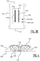
- Figure 4 shows a cross-section of an absorbent article according to an embodiment, which is similar to the embodiment as illustrated in Figures 1A and 1B .
- the bottom core wrap sheet 320 is substantially flat and covers the bottom of the absorbent core 300 whereas the liquid management structure 310 covers the upper portion of the absorbent core 300 as well as side portions thereof such that the liquid management structure 310 and the bottom core wrap sheet 320 enclose the absorbent core 300.
- the liquid management structure 310 covers the upper portion of the absorbent core 300
- the bottom core wrap sheet 320 covers the bottom of the absorbent core, as well as side portions thereof such that the liquid management structure 310 and the bottom core wrap sheet 320 enclose the absorbent core 300.
- the liquid management structure 310 partially overlaps with the bottom core wrap sheet 320 at the side edges of the upper portion of the absorbent core 300.
- Figures 5A and 5B illustrate an exemplary embodiment of an absorbent article, here a diaper.
- Figure 5A shows a cross-section of the absorbent article
- Figure 5B shows the absorbent article in its flat out, un-contracted state with the wearer side facing the viewer.
- the absorbent article comprises a liquid pervious topsheet 100, a liquid impervious backsheet 200, and an absorbent core 300 positioned between the liquid pervious topsheet 100 and the liquid impervious backsheet 200.
- the absorbent article has a first and second longitudinal edge 103, 104 and a first and second transverse edge 101, 102.
- the absorbent core 300 comprises a liquid management structure 310, a bottom core wrap sheet 320, and absorbent material 330 arranged partially between the liquid management structure 310 and the bottom core wrap sheet 320.
- the liquid management structure 310 comprises a connecting portion 311 which is attached to the bottom core wrap sheet 320 forming an attachment zone 313.
- the liquid management structure 310 further comprises edge portions 316, 317 covering a portion of the absorbent material 330. Each edge portion 316, 317 has a free edge 316', 317', wherein the free edges 316', 317' are not connected to the bottom core wrap sheet 320.
- the first edge portion 316 and the second edge portion 317 are located at opposite sides of the attachment portion 311.
- first edge portion 316 and the second edge portion 317 provide a stable structural basis for the formation of an attachment zone 313 and a corresponding channel.
- the absorbent material 330 swells such that the first edge portion 316 and the second edge portion 317 form embankments delimiting the channel for guiding the liquid.
- a portion of the absorbent material 330 is not covered by the liquid management structure 310.
- the liquid management structure 310 may be attached to the liquid pervious topsheet 100, e.g. using adhesive.
- the attachment zone 313 extends from the crotch region CR in the direction of the first and second transverse edge 101, 102.
- a channel is created at said attachment zone 313.
- the absorbent material 330 may swell upon wetting, and the edge portions 316, 317 may prevent the absorbent material 330 from entering the attachment zone 313 and help with formation of embankments delimiting the channel upon wetting.
- This embodiment allows the amount of raw material for manufacturing the liquid management structure 310 to be reduced, and as a result the manufacturing cost can be reduced. Meanwhile an absorbent article with good liquid distribution and absorption capacities can still be obtained.
- the liquid management structure 310 has a total surface area of S1 and the absorbent core 300 has a surface area of S0 defined by an area covered by the absorbent material 330 plus an area of the at least one attachment zone 313.
- S1 is smaller than 90% of S0, preferably S1 is smaller than 80% of S0, more preferably S1 is smaller than 70% of S0, even more preferably S1 is smaller than 60% of S0, even more preferably S1 is smaller than 50% of S0, most preferably S1 is smaller than 40% of S0.
- the attachment zone 313 has a center line CL, which is a straight line. In other embodiments, the center line CL may be a curve, a polyline, or any other shape.
- the center line is a line which is at the same distance of opposite edges of the attachment zone 313, and which preferably extends in a length direction of the attachment zone 313.
- the attachment zone 313 extends from a crotch region in the direction of the first and second transverse edge of the absorbent article 101, 102, which allows a better liquid distribution between crotch region and front/back portion of absorbent article.
- the at least one attachment zone 313 may extend in the direction from the first longitudinal edge 103 to the second longitudinal edge 104 of the absorbent article, which allows a better liquid distribution between left and right portions of absorbent article.
- the at least one attachment zone 313 is arranged symmetrically with respect to a longitudinal center line of absorbent core 300.
- a contour of the attachment zone 313 is adjacent to the absorbent material, which may comprise cellulosic fluff pulp and/or superabsorbent particles.
- a length of the attachment zone 313 is larger than 10% of the length of the absorbent core 300, more preferably larger than 30%, even more preferably larger than 50%, which allows a better liquid distribution over a larger area of the absorbent core 300.
- the attachment zone 313 may be a permanent attachment zone which remains attached when wetted, allowing the channel to distribute liquid during consecutive liquid insults.
- the liquid management structure 310 has a substantially rectangular shape.
- the liquid management structure 310 has a longitudinal dimension which is substantially 100% of the length of the absorbent core 300 and a transverse dimension which is about 60% of the width of the absorbent core 300.
- a rear and front edge of the liquid management structure 310 may be attached to a rear and front edge of the bottom core wrap sheet 320, respectively, to provide a stable and integrated structure of the absorbent core 300 while the use of material can still be reduced.
- the ratio of the longitudinal dimension of the liquid management structure 310 to the length of the absorbent core 300 may vary.
- the ratio of the transverse dimension of the liquid management structure 310 to the width of the absorbent core 300 may vary.
- the liquid managing structure 310 may have a longitudinal dimension which ranges from 50% to substantially 100% of the length of the absorbent core 300, and/or a transverse dimension which ranges from 50% to substantially 100% of the width of the absorbent core 300.
- a transverse dimension of the liquid management structure 310 and/or a transverse dimension of the bottom core wrap sheet 320 and the width of the absorbent core 300 may be within ⁇ 10% difference, preferably substantially the same, which allows an attachment between the liquid management structure 310 and the bottom core wrap sheet 320 by the longitudinal edges of the absorbent core 300.
- the at least one attachment between the liquid management structure 310 and bottom core wrap sheet 320 may be a permanent attachment, wherein the absorbent core 300 is configured such that, in a wetted state of absorbent core 300, the absorbent material 330 may extend partially over a bottom of the channel formed by the attachment.
- the attachment between the liquid management structure 310 and bottom core wrap sheet 320 may be a semi-permanent attachment configured to release after having been in contact with urine for a predetermined period of time, and the predetermined period of time is preferably smaller than 30 seconds.
- the attachment zone 313 is provided by means of continuous attachments in the longitudinal direction of the absorbent core in Figure 5A and 5B .
- the attachment zone may be provided by means of continuous attachments in the transversal direction of the absorbent core and/or discontinuous attachments in the transversal direction of the absorbent core and/or discontinuous attachments in the longitudinal direction of the absorbent core.
- the illustrated liquid management structure 310 is preferably essentially free of spunbond nonwoven material. More preferably, the liquid management structure 310 is essentially free of spunbond nonwoven material with a grammage or basis weight smaller than 15 g/m 2 . These materials are considered to have poor liquid acquisition and/or distribution capacities in comparison with nonwoven materials with a higher basis weight.
- the liquid management structure 310 has a grammage of at least 15 g/m 2 , preferably at least 17 g/m 2 , more preferably at least 19 g/m 2 , most preferably at least 20 g/m 2 . Carded nonwoven materials with a grammage of at least 15g/m 2 are preferred.
- the liquid management structure 310 may comprise meltblown nonwoven material and/or spunbond nonwoven material with a grammage of at least 15g/m 2 . This may contribute to the liquid acquisition and/or distribution capacities of the absorbent article.
- the liquid management structure 310 may be made of single substrate, material or nonwoven, or may comprise two or more substrates, materials or nonwovens. Preferably, the liquid management structure 310 is in contact with a surface portion of the absorbent material 330. This improves the transition and distribution of the liquid between the liquid management structure 310 and the absorbent material.
- Figures 6A, 6B , 6C and 6D are top plan views of exemplary embodiments of an absorbent article, wherein Figures 6A and 6C illustrate embodiments comprising one liquid management structure 310 having two attachment zones 313a, 313b, and Figures 6B and 6D illustrate embodiments comprising two liquid management structures 310a, 310b, wherein each liquid management structure 310a, 310b has one corresponding attachment zone 313a, 313b.
- the embodiment of Figure 6A corresponds to the embodiment as previously described in view of Figures 3A and 3B .
- edge portions 316 and 317 of the liquid management structure 310 are indicated which do not have free edges.
- the liquid management structure 310 has similar dimensions as compared to the absorbent core 300, more in particular since S1 is substantially equal to S0, the liquid management structure 310 can be connected to the bottom core wrap sheet 320 at the longitudinal edges of the edge portions 316 and 317.
- the total surface area S1 of the liquid management structure 310 is smaller than the surface area S0 of the absorbent core 300. More in particular, the total surface area S1 of the liquid management structure 310 is smaller than 90% of the surface area S0 of the absorbent core 300.
- edge portions 316 and 317 have free edges 316' and 317', respectively, in the longitudinal direction of the absorbent core.
- Figure 6B illustrates an embodiment comprising two liquid management structures 310a, 310b, wherein each liquid management structure 310a, 310b has one corresponding attachment zone 313a, 313b and has two edge portions 316a, 317a, 316b, 317b with corresponding free edges 316a', 317a', 316b', 317b'.
- the first liquid management structure 310a has a total surface area of S1a
- the second liquid management structure 310b has a total surface area of S1b
- the absorbent core 300 has a surface area of S0 defined by an area covered by the absorbent material 330 plus an area of the attachment zones 313a, 313b.
- S1a and S1b may be similar, preferably substantially the same, and S1a+S1b is smaller than 90% of S0, preferably 80% of S0, more preferably 70% of S0, and most preferably 60% of S0.
- the distance between the liquid management structure 310a and the second liquid management structure 310b may be at least 5% of the width of the absorbent core 300.
- Figure 6D illustrates an embodiment comprising two liquid management structures 310a, 310b, wherein each liquid management structure 310a, 310b has one corresponding attachment zone 313a, 313b and has two edge portions 316a, 317a, 316b, 317b wherein edge portions 317a, 316b have corresponding free edges 317a', 316b' and edge portions 316a, 317b have corresponding longitudinal edges which may be connected to the bottom core wrap sheet 320.
- the first liquid management structure 310a has a total surface area of S1a
- the second liquid management structure 310b has a total surface area of S1b
- the absorbent core 300 has a surface area of S0 defined by an area covered by the absorbent material 330 plus an area of the attachment zones 313a, 313b.
- S1a and S1b may be similar, preferably substantially the same, and S1a+S1b is smaller than 90% of S0, preferably 80% of S0, more preferably 70% of S0, and most preferably 60% of S0.
- the distance between the liquid management structure 310a and the second liquid management structure 310b may be at least 5% of the width of the absorbent core 300.
- Figure 7 shows an exemplary absorbent article in its flat out, un-contracted state with the wearer side facing the viewer.
- the absorbent article may also be a pant or an adult incontinence garment or the like.
- the absorbent article comprises a liquid pervious topsheet, a liquid impervious backsheet, and an absorbent core 300 positioned in between the topsheet and the backsheet.
- the absorbent core 300 comprises absorbent material 330 between a liquid management structure 310 and a bottom core wrap sheet 320.
- the absorbent article has a first and second longitudinal edge 103, 104 and a first and second transverse edge 101, 102.
- the absorbent core 300 is provided with a plurality of attachment zones 313a, 313b, 313c, 313d comprising at least a first attachment zone 313a and a second attachment zone 313b.
- the first and second attachment zones extend next to each other from the crotch region CR in the direction of the first and/or second transverse edge 101, 102.
- first and second attachment zone 313a, 313b the liquid management structure 310 is attached to the bottom core wrap sheet 320
- First attachment zone 313a and second attachment zone 313b are substantially parallel and run in the longitudinal direction of absorbent core 300. However, it is also possible for first and second attachment zone 313a, 313b to extend under a small angle with respect to the longitudinal direction of absorbent core 300, e.g. an angle between 5 and 10°. For example, first and second attachment zone 313a, 313b may be diverging slightly outwardly in the direction of second transverse edge 102. Preferably first attachment zone 313a and second attachment zone 313b are arranged symmetrically with respect to a longitudinal center line CL of absorbent core 300.
- the absorbent article is further provided with a third and a fourth attachment zone 313c, 313d located at a distance each other.
- Third and fourth attachment zone 313c, 313d each extend from the crotch region in the direction of first transverse edge 101.
- the distance between first and second attachment zone 313a, 313b may be different from the distance between third and fourth attachment zone 313c, 313d.
- Third attachment zone 313c and fourth attachment zone 313d are substantially parallel and run in the longitudinal direction of absorbent core 300.
- third and fourth attachment zone 313c, 313d may extend under a small angle with respect to the longitudinal direction of absorbent core 300, e.g. an angle between 5 and 10°.
- third and fourth attachment zone 313c, 313d may be diverging slightly outwardly in the direction of first transverse edge 101.
- third attachment zone 313c and fourth attachment zone 313d are arranged symmetrically with respect to a longitudinal center line CL of absorbent core 300.
- liquid management structure 310 which comprises four attachment zones 313a, 313b, 313c, 313d and which comprises no free edges.
- the liquid management structure has a total surface area of S1 which is substantially equal to S0 which is the surface area of the absorbent core defined by an area covered by the absorbent material plus an area of the four attachment zones 313a, 313b, 313c, 313d.
- the absorbent core 300 comprises a liquid management structure 310, a bottom core wrap sheet 320 (not shown), and absorbent material 330 arranged between the liquid management structure 310 and the bottom core wrap sheet 320.
- the liquid management structure 310 comprises a first connecting portion which is attached to the bottom core wrap sheet 320 forming a first attachment zone 313a.
- the liquid management structure 310 comprises a second connecting portion which is attached to the bottom core wrap sheet 320 forming a second attachment zone 313b.
- the first attachment zone 313a and the second attachment zone 313b diverge from the crotch region in the direction of a front and rear transverse edge of absorbent article.
- the center line of the first attachment zone 313a and the second attachment zone 313b may have a curved shape.
- the liquid management structure 310 Seen in a top view of the absorbent core 300, has a total surface area of S1 and the absorbent core has a surface area of S0. S1 and S0 are substantially the same.
- the absorbent core 300 comprises a liquid management structure 310, a bottom core wrap sheet 320 (not shown), and absorbent material 330 arranged between the liquid management structure 310 and the bottom core wrap sheet 320.
- the liquid management structure 310 comprises a first connecting portion which is attached to the bottom core wrap sheet 320 forming a first attachment zone 313a.
- the liquid management structure 310 comprises a second connecting portion which is attached to the bottom core wrap sheet 320 forming a second attachment zone 313b.
- the first attachment zone 313a and the second attachment zone 313b together form a substantially X-shaped zone.
- the crossing point is on a longitudinal center line of the absorbent core 300 extending between the transverse edges.
- the crossing point is in the crotch portion of the absorbent core 300.
- the liquid management structure 310 Seen in a top view of the absorbent core 300, the liquid management structure 310 has a total surface area of S1 and the absorbent core has a surface area of S0. S1 and S0 are substantially the same.
- the absorbent core 300 comprises a liquid management structure 310, a bottom core wrap sheet 320 (not shown), and absorbent material 330 arranged between the liquid management structure 310 and the bottom core wrap sheet 320.
- the liquid management structure 310 comprises a first connecting portion which is attached to the bottom core wrap sheet 320 forming a first attachment zone 313a.
- the liquid management structure 310 comprises a second connecting portion which is attached to the bottom core wrap sheet 320 forming a second attachment zone 313b. Between the first attachment zone 313a and the second attachment zone 313b a bridge zone 145 is formed which allows a liquid flow F between the first and the second longitudinal edge of the absorbent core 300 by capillary action through the absorbent material and/or by mass flow, such that upon wetting of the absorbent material, a first channel and a second channel in front of one another are created, wherein the bridge zone 145 extends between the first and second channel.
- a minimum distance between said first and second channel is preferably larger than 3 mm and more preferably larger than 5 mm.
- the liquid management structure 310 has a total surface area of S1 and the absorbent core has a surface area of S0.
- S1 and S0 are substantially the same.
- only one liquid management structure 310 is provided which comprises two attachment zones 313a, 313b and which comprises no free edges.
- the liquid management structure has a total surface area of S1 which is substantially equal to S0 which is the surface area of the absorbent core defined by an area covered by the absorbent material plus an area of the two attachment zones 313a, 313b.
- attachment zones 313a, 313b may be provided by 1 or 2 separate liquid managing structures, wherein each liquid managing structure may haves none, 1, 2, 3 or 4 free edges, wherein the total combined surface area S1 of the liquid managing structure(s) is smaller than 90% of S0 (see Figures 6A-6D ).
- each liquid managing structure may haves none, 1, 2, 3 or 4 free edges, wherein the total combined surface area S1 of the liquid managing structure(s) is smaller than 90% of S0 (see Figures 6A-6D ).
Landscapes
- Health & Medical Sciences (AREA)
- Engineering & Computer Science (AREA)
- Life Sciences & Earth Sciences (AREA)
- Biomedical Technology (AREA)
- Heart & Thoracic Surgery (AREA)
- Vascular Medicine (AREA)
- Epidemiology (AREA)
- Animal Behavior & Ethology (AREA)
- General Health & Medical Sciences (AREA)
- Public Health (AREA)
- Veterinary Medicine (AREA)
- Manufacturing & Machinery (AREA)
- Absorbent Articles And Supports Therefor (AREA)
- Orthopedics, Nursing, And Contraception (AREA)
Priority Applications (10)
| Application Number | Priority Date | Filing Date | Title |
|---|---|---|---|
| EP18168885.4A EP3560469B1 (de) | 2018-04-24 | 2018-04-24 | Saugfähiger artikel |
| ES18168885T ES2881224T3 (es) | 2018-04-24 | 2018-04-24 | Artículo absorbente |
| PL18168885T PL3560469T3 (pl) | 2018-04-24 | 2018-04-24 | Wyrób chłonny |
| EP19721233.5A EP3784189A1 (de) | 2018-04-24 | 2019-04-24 | Absorbierender artikel |
| MX2020011195A MX2020011195A (es) | 2018-04-24 | 2019-04-24 | Articulo absorbente. |
| CA3097490A CA3097490A1 (en) | 2018-04-24 | 2019-04-24 | Absorbent article |
| AU2019258304A AU2019258304A1 (en) | 2018-04-24 | 2019-04-24 | Absorbent article |
| US15/733,774 US20210236352A1 (en) | 2018-04-24 | 2019-04-24 | Absorbent article |
| PCT/EP2019/060462 WO2019206961A1 (en) | 2018-04-24 | 2019-04-24 | Absorbent article |
| BR112020021639-9A BR112020021639A2 (pt) | 2018-04-24 | 2019-04-24 | artigo absorvente |
Applications Claiming Priority (1)
| Application Number | Priority Date | Filing Date | Title |
|---|---|---|---|
| EP18168885.4A EP3560469B1 (de) | 2018-04-24 | 2018-04-24 | Saugfähiger artikel |
Publications (2)
| Publication Number | Publication Date |
|---|---|
| EP3560469A1 true EP3560469A1 (de) | 2019-10-30 |
| EP3560469B1 EP3560469B1 (de) | 2021-06-16 |
Family
ID=62062854
Family Applications (2)
| Application Number | Title | Priority Date | Filing Date |
|---|---|---|---|
| EP18168885.4A Active EP3560469B1 (de) | 2018-04-24 | 2018-04-24 | Saugfähiger artikel |
| EP19721233.5A Pending EP3784189A1 (de) | 2018-04-24 | 2019-04-24 | Absorbierender artikel |
Family Applications After (1)
| Application Number | Title | Priority Date | Filing Date |
|---|---|---|---|
| EP19721233.5A Pending EP3784189A1 (de) | 2018-04-24 | 2019-04-24 | Absorbierender artikel |
Country Status (9)
| Country | Link |
|---|---|
| US (1) | US20210236352A1 (de) |
| EP (2) | EP3560469B1 (de) |
| AU (1) | AU2019258304A1 (de) |
| BR (1) | BR112020021639A2 (de) |
| CA (1) | CA3097490A1 (de) |
| ES (1) | ES2881224T3 (de) |
| MX (1) | MX2020011195A (de) |
| PL (1) | PL3560469T3 (de) |
| WO (1) | WO2019206961A1 (de) |
Cited By (9)
| Publication number | Priority date | Publication date | Assignee | Title |
|---|---|---|---|---|
| EP3711732B1 (de) | 2019-03-21 | 2021-11-17 | Ontex BV | Absorbierender artikel und verfahren zur herstellung |
| EP3799848B1 (de) | 2020-03-19 | 2022-04-13 | Ontex BV | Absorbierende artikel und verfahren zur herstellung |
| EP4014937A1 (de) * | 2020-12-18 | 2022-06-22 | Drylock Technologies NV | Absorbierender artikel mit verbesserter bodenverteilungsanordnung |
| WO2022129643A1 (en) * | 2020-12-18 | 2022-06-23 | Drylock Technologies Nv | Absorbent article with improved structure |
| WO2022129636A1 (en) * | 2020-12-18 | 2022-06-23 | Drylock Technologies Nv | Absorbent article with improved capillary acceleration sheet |
| WO2022129635A1 (en) * | 2020-12-18 | 2022-06-23 | Drylock Technologies Nv | Absorbent article with resilient bottom layer |
| NL2027169B1 (en) * | 2020-12-18 | 2022-07-15 | Drylock Tech Nv | Absorbent article with improved capillary acceleration sheet |
| NL2028199B1 (en) * | 2021-05-12 | 2022-11-29 | Drylock Tech Nv | Absorbent article with resilient bottom layer |
| WO2023063897A1 (en) * | 2021-10-14 | 2023-04-20 | Evyap Sabun Yag Gliserin Sanayi Ve Ticaret Anonim Sirketi | An absorbent hygiene product |
Families Citing this family (1)
| Publication number | Priority date | Publication date | Assignee | Title |
|---|---|---|---|---|
| USD979181S1 (en) * | 2019-05-10 | 2023-02-28 | Drylock Technologies N.V. | Absorbent underpants |
Citations (5)
| Publication number | Priority date | Publication date | Assignee | Title |
|---|---|---|---|---|
| WO2012052173A1 (en) | 2010-10-20 | 2012-04-26 | Vynka Bvba | Method and apparatus for producing an environmentally friendly absorbent structure |
| EP2450012A1 (de) * | 2010-10-13 | 2012-05-09 | Romanova bvba starter | Verbesserte absorbierende Struktur |
| EP2627294A1 (de) | 2010-10-13 | 2013-08-21 | Romanova bvba starter | Verfahren und vorrichtung zur herstellung von verbundstofffüllern |
| US20170079858A1 (en) * | 2015-09-22 | 2017-03-23 | The Procter & Gamble Company | Absorbent articles having curved channels |
| EP3167858A1 (de) * | 2015-11-16 | 2017-05-17 | The Procter and Gamble Company | Absorbierende kerne mit materialfreien bereichen |
Family Cites Families (11)
| Publication number | Priority date | Publication date | Assignee | Title |
|---|---|---|---|---|
| US20040158212A1 (en) | 2003-02-10 | 2004-08-12 | The Procter & Gamble Company | Disposable absorbent article comprising a durable hydrophilic core wrap |
| US20070044903A1 (en) | 2005-08-30 | 2007-03-01 | Kimberly-Clark Worldwide, Inc. | Method and apparatus for making absorbent article with core wrap |
| US8198506B2 (en) | 2006-04-21 | 2012-06-12 | Kimberly-Clark Worldwide, Inc. | Stabilized absorbent composite |
| IN2015DN03110A (de) | 2012-11-13 | 2015-10-02 | Procter & Gamble | |
| EP2813201B1 (de) | 2013-06-14 | 2017-11-01 | The Procter and Gamble Company | Saugfähiger Artikel und saugfähiger Kern mit Kanalformung bei Nässe |
| US10335324B2 (en) * | 2013-08-27 | 2019-07-02 | The Procter & Gamble Company | Absorbent articles with channels |
| EP3191049A1 (de) | 2014-09-12 | 2017-07-19 | The Procter and Gamble Company | Saugfähiger artikel mit einer deckschicht/einem erfassungsvlieslaminat |
| JP6647015B2 (ja) | 2014-12-16 | 2020-02-14 | 花王株式会社 | 吸収性物品 |
| US10376428B2 (en) * | 2015-01-16 | 2019-08-13 | The Procter & Gamble Company | Absorbent pant with advantageously channeled absorbent core structure and bulge-reducing features |
| US10070997B2 (en) | 2015-01-16 | 2018-09-11 | The Procter & Gamble Company | Absorbent pant with advantageously channeled absorbent core structure and bulge-reducing features |
| US10806640B2 (en) | 2016-03-30 | 2020-10-20 | Basf Se | Ultrathin fluid-absorbent article |
-
2018
- 2018-04-24 PL PL18168885T patent/PL3560469T3/pl unknown
- 2018-04-24 EP EP18168885.4A patent/EP3560469B1/de active Active
- 2018-04-24 ES ES18168885T patent/ES2881224T3/es active Active
-
2019
- 2019-04-24 CA CA3097490A patent/CA3097490A1/en active Pending
- 2019-04-24 WO PCT/EP2019/060462 patent/WO2019206961A1/en unknown
- 2019-04-24 US US15/733,774 patent/US20210236352A1/en active Pending
- 2019-04-24 MX MX2020011195A patent/MX2020011195A/es unknown
- 2019-04-24 AU AU2019258304A patent/AU2019258304A1/en active Pending
- 2019-04-24 BR BR112020021639-9A patent/BR112020021639A2/pt unknown
- 2019-04-24 EP EP19721233.5A patent/EP3784189A1/de active Pending
Patent Citations (5)
| Publication number | Priority date | Publication date | Assignee | Title |
|---|---|---|---|---|
| EP2450012A1 (de) * | 2010-10-13 | 2012-05-09 | Romanova bvba starter | Verbesserte absorbierende Struktur |
| EP2627294A1 (de) | 2010-10-13 | 2013-08-21 | Romanova bvba starter | Verfahren und vorrichtung zur herstellung von verbundstofffüllern |
| WO2012052173A1 (en) | 2010-10-20 | 2012-04-26 | Vynka Bvba | Method and apparatus for producing an environmentally friendly absorbent structure |
| US20170079858A1 (en) * | 2015-09-22 | 2017-03-23 | The Procter & Gamble Company | Absorbent articles having curved channels |
| EP3167858A1 (de) * | 2015-11-16 | 2017-05-17 | The Procter and Gamble Company | Absorbierende kerne mit materialfreien bereichen |
Cited By (12)
| Publication number | Priority date | Publication date | Assignee | Title |
|---|---|---|---|---|
| EP3711732B1 (de) | 2019-03-21 | 2021-11-17 | Ontex BV | Absorbierender artikel und verfahren zur herstellung |
| EP3799848B1 (de) | 2020-03-19 | 2022-04-13 | Ontex BV | Absorbierende artikel und verfahren zur herstellung |
| EP4014937A1 (de) * | 2020-12-18 | 2022-06-22 | Drylock Technologies NV | Absorbierender artikel mit verbesserter bodenverteilungsanordnung |
| WO2022129643A1 (en) * | 2020-12-18 | 2022-06-23 | Drylock Technologies Nv | Absorbent article with improved structure |
| WO2022129636A1 (en) * | 2020-12-18 | 2022-06-23 | Drylock Technologies Nv | Absorbent article with improved capillary acceleration sheet |
| WO2022128391A1 (en) * | 2020-12-18 | 2022-06-23 | Drylock Technologies Nv | Absorbent article with improved bottom distribution assembly |
| WO2022129635A1 (en) * | 2020-12-18 | 2022-06-23 | Drylock Technologies Nv | Absorbent article with resilient bottom layer |
| NL2027163B1 (en) * | 2020-12-18 | 2022-07-15 | Drylock Tech Nv | Absorbent article with improved bottom distribution assembly |
| NL2027169B1 (en) * | 2020-12-18 | 2022-07-15 | Drylock Tech Nv | Absorbent article with improved capillary acceleration sheet |
| WO2022129642A3 (en) * | 2020-12-18 | 2022-08-11 | Drylock Technologies Nv | Absorbent article with improved structure |
| NL2028199B1 (en) * | 2021-05-12 | 2022-11-29 | Drylock Tech Nv | Absorbent article with resilient bottom layer |
| WO2023063897A1 (en) * | 2021-10-14 | 2023-04-20 | Evyap Sabun Yag Gliserin Sanayi Ve Ticaret Anonim Sirketi | An absorbent hygiene product |
Also Published As
| Publication number | Publication date |
|---|---|
| BR112020021639A2 (pt) | 2021-01-26 |
| EP3784189A1 (de) | 2021-03-03 |
| WO2019206961A1 (en) | 2019-10-31 |
| EP3560469B1 (de) | 2021-06-16 |
| AU2019258304A1 (en) | 2020-11-12 |
| US20210236352A1 (en) | 2021-08-05 |
| CA3097490A1 (en) | 2019-10-31 |
| PL3560469T3 (pl) | 2021-09-27 |
| MX2020011195A (es) | 2021-01-29 |
| ES2881224T3 (es) | 2021-11-29 |
Similar Documents
| Publication | Publication Date | Title |
|---|---|---|
| EP3560469B1 (de) | Saugfähiger artikel | |
| US20230039880A1 (en) | Absorbent article with capillary acceleration sheet | |
| EP3549566B1 (de) | Saugfähiger artikel mit reduziertem saugfähigem kern | |
| EP2450012A1 (de) | Verbesserte absorbierende Struktur | |
| EP3569208A1 (de) | Absorbierender artikel mit abstandselement | |
| EP4014937B1 (de) | Absorbierender artikel mit verbesserter bodenverteilungsanordnung | |
| NL2026975B1 (en) | Absorbent article with improved capillary acceleration sheet | |
| US20240024172A1 (en) | Absorbent article with improved capillary acceleration sheet | |
| NL2027169B1 (en) | Absorbent article with improved capillary acceleration sheet | |
| NL2028199B1 (en) | Absorbent article with resilient bottom layer | |
| US20240041668A1 (en) | Absorbent article with resilient bottom layer | |
| US20240099911A1 (en) | Absorbent article with improved structure | |
| RU2805155C2 (ru) | Впитывающее изделие |
Legal Events
| Date | Code | Title | Description |
|---|---|---|---|
| PUAI | Public reference made under article 153(3) epc to a published international application that has entered the european phase |
Free format text: ORIGINAL CODE: 0009012 |
|
| STAA | Information on the status of an ep patent application or granted ep patent |
Free format text: STATUS: THE APPLICATION HAS BEEN PUBLISHED |
|
| AK | Designated contracting states |
Kind code of ref document: A1 Designated state(s): AL AT BE BG CH CY CZ DE DK EE ES FI FR GB GR HR HU IE IS IT LI LT LU LV MC MK MT NL NO PL PT RO RS SE SI SK SM TR |
|
| AX | Request for extension of the european patent |
Extension state: BA ME |
|
| STAA | Information on the status of an ep patent application or granted ep patent |
Free format text: STATUS: REQUEST FOR EXAMINATION WAS MADE |
|
| 17P | Request for examination filed |
Effective date: 20200429 |
|
| RBV | Designated contracting states (corrected) |
Designated state(s): AL AT BE BG CH CY CZ DE DK EE ES FI FR GB GR HR HU IE IS IT LI LT LU LV MC MK MT NL NO PL PT RO RS SE SI SK SM TR |
|
| STAA | Information on the status of an ep patent application or granted ep patent |
Free format text: STATUS: EXAMINATION IS IN PROGRESS |
|
| STAA | Information on the status of an ep patent application or granted ep patent |
Free format text: STATUS: EXAMINATION IS IN PROGRESS |
|
| 17Q | First examination report despatched |
Effective date: 20200930 |
|
| GRAP | Despatch of communication of intention to grant a patent |
Free format text: ORIGINAL CODE: EPIDOSNIGR1 |
|
| STAA | Information on the status of an ep patent application or granted ep patent |
Free format text: STATUS: GRANT OF PATENT IS INTENDED |
|
| GRAS | Grant fee paid |
Free format text: ORIGINAL CODE: EPIDOSNIGR3 |
|
| GRAA | (expected) grant |
Free format text: ORIGINAL CODE: 0009210 |
|
| STAA | Information on the status of an ep patent application or granted ep patent |
Free format text: STATUS: THE PATENT HAS BEEN GRANTED |
|
| TPAC | Observations filed by third parties |
Free format text: ORIGINAL CODE: EPIDOSNTIPA |
|
| INTG | Intention to grant announced |
Effective date: 20210420 |
|
| AK | Designated contracting states |
Kind code of ref document: B1 Designated state(s): AL AT BE BG CH CY CZ DE DK EE ES FI FR GB GR HR HU IE IS IT LI LT LU LV MC MK MT NL NO PL PT RO RS SE SI SK SM TR |
|
| REG | Reference to a national code |
Ref country code: GB Ref legal event code: FG4D |
|
| REG | Reference to a national code |
Ref country code: CH Ref legal event code: EP |
|
| REG | Reference to a national code |
Ref country code: DE Ref legal event code: R096 Ref document number: 602018018540 Country of ref document: DE |
|
| REG | Reference to a national code |
Ref country code: AT Ref legal event code: REF Ref document number: 1401714 Country of ref document: AT Kind code of ref document: T Effective date: 20210715 |
|
| REG | Reference to a national code |
Ref country code: IE Ref legal event code: FG4D |
|
| REG | Reference to a national code |
Ref country code: DE Ref legal event code: R026 Ref document number: 602018018540 Country of ref document: DE |
|
| REG | Reference to a national code |
Ref country code: SE Ref legal event code: TRGR |
|
| PLBI | Opposition filed |
Free format text: ORIGINAL CODE: 0009260 |
|
| REG | Reference to a national code |
Ref country code: NL Ref legal event code: FP |
|
| REG | Reference to a national code |
Ref country code: FI Ref legal event code: MDE Opponent name: ONTEX BV |
|
| 26 | Opposition filed |
Opponent name: ONTEX BV Effective date: 20210730 |
|
| REG | Reference to a national code |
Ref country code: LT Ref legal event code: MG9D |
|
| PG25 | Lapsed in a contracting state [announced via postgrant information from national office to epo] |
Ref country code: HR Free format text: LAPSE BECAUSE OF FAILURE TO SUBMIT A TRANSLATION OF THE DESCRIPTION OR TO PAY THE FEE WITHIN THE PRESCRIBED TIME-LIMIT Effective date: 20210616 Ref country code: LT Free format text: LAPSE BECAUSE OF FAILURE TO SUBMIT A TRANSLATION OF THE DESCRIPTION OR TO PAY THE FEE WITHIN THE PRESCRIBED TIME-LIMIT Effective date: 20210616 Ref country code: FI Free format text: LAPSE BECAUSE OF FAILURE TO SUBMIT A TRANSLATION OF THE DESCRIPTION OR TO PAY THE FEE WITHIN THE PRESCRIBED TIME-LIMIT Effective date: 20210616 Ref country code: BG Free format text: LAPSE BECAUSE OF FAILURE TO SUBMIT A TRANSLATION OF THE DESCRIPTION OR TO PAY THE FEE WITHIN THE PRESCRIBED TIME-LIMIT Effective date: 20210916 |
|
| REG | Reference to a national code |
Ref country code: AT Ref legal event code: MK05 Ref document number: 1401714 Country of ref document: AT Kind code of ref document: T Effective date: 20210616 |
|
| REG | Reference to a national code |
Ref country code: ES Ref legal event code: FG2A Ref document number: 2881224 Country of ref document: ES Kind code of ref document: T3 Effective date: 20211129 |
|
| PG25 | Lapsed in a contracting state [announced via postgrant information from national office to epo] |
Ref country code: GR Free format text: LAPSE BECAUSE OF FAILURE TO SUBMIT A TRANSLATION OF THE DESCRIPTION OR TO PAY THE FEE WITHIN THE PRESCRIBED TIME-LIMIT Effective date: 20210917 Ref country code: RS Free format text: LAPSE BECAUSE OF FAILURE TO SUBMIT A TRANSLATION OF THE DESCRIPTION OR TO PAY THE FEE WITHIN THE PRESCRIBED TIME-LIMIT Effective date: 20210616 Ref country code: LV Free format text: LAPSE BECAUSE OF FAILURE TO SUBMIT A TRANSLATION OF THE DESCRIPTION OR TO PAY THE FEE WITHIN THE PRESCRIBED TIME-LIMIT Effective date: 20210616 Ref country code: NO Free format text: LAPSE BECAUSE OF FAILURE TO SUBMIT A TRANSLATION OF THE DESCRIPTION OR TO PAY THE FEE WITHIN THE PRESCRIBED TIME-LIMIT Effective date: 20210916 |
|
| PG25 | Lapsed in a contracting state [announced via postgrant information from national office to epo] |
Ref country code: RO Free format text: LAPSE BECAUSE OF FAILURE TO SUBMIT A TRANSLATION OF THE DESCRIPTION OR TO PAY THE FEE WITHIN THE PRESCRIBED TIME-LIMIT Effective date: 20210616 Ref country code: PT Free format text: LAPSE BECAUSE OF FAILURE TO SUBMIT A TRANSLATION OF THE DESCRIPTION OR TO PAY THE FEE WITHIN THE PRESCRIBED TIME-LIMIT Effective date: 20211018 Ref country code: AT Free format text: LAPSE BECAUSE OF FAILURE TO SUBMIT A TRANSLATION OF THE DESCRIPTION OR TO PAY THE FEE WITHIN THE PRESCRIBED TIME-LIMIT Effective date: 20210616 Ref country code: SM Free format text: LAPSE BECAUSE OF FAILURE TO SUBMIT A TRANSLATION OF THE DESCRIPTION OR TO PAY THE FEE WITHIN THE PRESCRIBED TIME-LIMIT Effective date: 20210616 Ref country code: SK Free format text: LAPSE BECAUSE OF FAILURE TO SUBMIT A TRANSLATION OF THE DESCRIPTION OR TO PAY THE FEE WITHIN THE PRESCRIBED TIME-LIMIT Effective date: 20210616 Ref country code: EE Free format text: LAPSE BECAUSE OF FAILURE TO SUBMIT A TRANSLATION OF THE DESCRIPTION OR TO PAY THE FEE WITHIN THE PRESCRIBED TIME-LIMIT Effective date: 20210616 |
|
| PLAX | Notice of opposition and request to file observation + time limit sent |
Free format text: ORIGINAL CODE: EPIDOSNOBS2 |
|
| PG25 | Lapsed in a contracting state [announced via postgrant information from national office to epo] |
Ref country code: DK Free format text: LAPSE BECAUSE OF FAILURE TO SUBMIT A TRANSLATION OF THE DESCRIPTION OR TO PAY THE FEE WITHIN THE PRESCRIBED TIME-LIMIT Effective date: 20210616 |
|
| PG25 | Lapsed in a contracting state [announced via postgrant information from national office to epo] |
Ref country code: AL Free format text: LAPSE BECAUSE OF FAILURE TO SUBMIT A TRANSLATION OF THE DESCRIPTION OR TO PAY THE FEE WITHIN THE PRESCRIBED TIME-LIMIT Effective date: 20210616 |
|
| PLBB | Reply of patent proprietor to notice(s) of opposition received |
Free format text: ORIGINAL CODE: EPIDOSNOBS3 |
|
| PG25 | Lapsed in a contracting state [announced via postgrant information from national office to epo] |
Ref country code: MC Free format text: LAPSE BECAUSE OF FAILURE TO SUBMIT A TRANSLATION OF THE DESCRIPTION OR TO PAY THE FEE WITHIN THE PRESCRIBED TIME-LIMIT Effective date: 20210616 Ref country code: LU Free format text: LAPSE BECAUSE OF NON-PAYMENT OF DUE FEES Effective date: 20220424 |
|
| PGFP | Annual fee paid to national office [announced via postgrant information from national office to epo] |
Ref country code: NL Payment date: 20230426 Year of fee payment: 6 |
|
| P01 | Opt-out of the competence of the unified patent court (upc) registered |
Effective date: 20230526 |
|
| PGFP | Annual fee paid to national office [announced via postgrant information from national office to epo] |
Ref country code: IT Payment date: 20230419 Year of fee payment: 6 Ref country code: IE Payment date: 20230427 Year of fee payment: 6 Ref country code: FR Payment date: 20230425 Year of fee payment: 6 Ref country code: ES Payment date: 20230503 Year of fee payment: 6 Ref country code: DE Payment date: 20230427 Year of fee payment: 6 Ref country code: CZ Payment date: 20230412 Year of fee payment: 6 Ref country code: CH Payment date: 20230502 Year of fee payment: 6 |
|
| PGFP | Annual fee paid to national office [announced via postgrant information from national office to epo] |
Ref country code: SE Payment date: 20230427 Year of fee payment: 6 Ref country code: PL Payment date: 20230405 Year of fee payment: 6 |
|
| PGFP | Annual fee paid to national office [announced via postgrant information from national office to epo] |
Ref country code: BE Payment date: 20230427 Year of fee payment: 6 |
|
| PGFP | Annual fee paid to national office [announced via postgrant information from national office to epo] |
Ref country code: GB Payment date: 20230427 Year of fee payment: 6 |
|
| PG25 | Lapsed in a contracting state [announced via postgrant information from national office to epo] |
Ref country code: HU Free format text: LAPSE BECAUSE OF FAILURE TO SUBMIT A TRANSLATION OF THE DESCRIPTION OR TO PAY THE FEE WITHIN THE PRESCRIBED TIME-LIMIT; INVALID AB INITIO Effective date: 20180424 |
|
| PLCK | Communication despatched that opposition was rejected |
Free format text: ORIGINAL CODE: EPIDOSNREJ1 |