EP3560322A1 - Rundballenpresse - Google Patents
Rundballenpresse Download PDFInfo
- Publication number
- EP3560322A1 EP3560322A1 EP19155637.2A EP19155637A EP3560322A1 EP 3560322 A1 EP3560322 A1 EP 3560322A1 EP 19155637 A EP19155637 A EP 19155637A EP 3560322 A1 EP3560322 A1 EP 3560322A1
- Authority
- EP
- European Patent Office
- Prior art keywords
- wrapping
- round
- housing
- loading arm
- arm
- Prior art date
- Legal status (The legal status is an assumption and is not a legal conclusion. Google has not performed a legal analysis and makes no representation as to the accuracy of the status listed.)
- Granted
Links
Images


Classifications
-
- A—HUMAN NECESSITIES
- A01—AGRICULTURE; FORESTRY; ANIMAL HUSBANDRY; HUNTING; TRAPPING; FISHING
- A01F—PROCESSING OF HARVESTED PRODUCE; HAY OR STRAW PRESSES; DEVICES FOR STORING AGRICULTURAL OR HORTICULTURAL PRODUCE
- A01F15/00—Baling presses for straw, hay or the like
- A01F15/07—Rotobalers, i.e. machines for forming cylindrical bales by winding and pressing
-
- A—HUMAN NECESSITIES
- A01—AGRICULTURE; FORESTRY; ANIMAL HUSBANDRY; HUNTING; TRAPPING; FISHING
- A01F—PROCESSING OF HARVESTED PRODUCE; HAY OR STRAW PRESSES; DEVICES FOR STORING AGRICULTURAL OR HORTICULTURAL PRODUCE
- A01F15/00—Baling presses for straw, hay or the like
- A01F15/07—Rotobalers, i.e. machines for forming cylindrical bales by winding and pressing
- A01F15/071—Wrapping devices
- A01F2015/0735—Combined machines that include a press bale and a wrapping device in a further step, e.g. turning table, not in the same closed pressing chamber
Definitions
- the invention relates to a round baler with a winding device for wrapping round bales according to the preamble of claim 1.
- Round balers are used in agriculture to absorb, for example, stored in the swath halmianos crop such as straw, hay, grass or the like and to round, essentially cylindrical bales, so-called round bales to press.
- the crop is compressed in a baling chamber of the round baler to form a round bale, wherein the pressing chamber may be circumferentially bounded by one or more rotating belts and / or rotating steel rollers.
- the pressed round bales are usually bound after reaching a predetermined size with laces and / or a network and ejected through a rear flap opening of the pressing chamber and passed to a winding chamber downstream winding device.
- the wrapping of a round bale takes place especially when processing grass and / or clover, since the crop can be stored in the round bale by the wrapping material, usually a foil, largely to the exclusion of air, whereby a subsequent fermentation to silage can be made possible.
- the round bale is placed on the field after pressing and / or wrapping by the winding device.
- such a round baler which has a bale wrapper at the rear, which essentially comprises a wrapping table for receiving a pressed round bale and a wrapping arm which can be rotated about a vertical axis.
- the two-part wrapping arm is in each case equipped with a foil holder at the end so that a round bale lying on the wrapping table can be wrapped with foil during rotation of the wrapping arm.
- the round bale is additionally rotated about a horizontal axis of rotation during the wrapping on the changing table, the round bale is wrapped on all sides with foil after completion of the winding process.
- Such round balers with a winding device require due to the arrangement of the winding device behind the pressing chamber and the space required by the winding device during winding and conditional by the winding device a large amount of space, which can be a hindrance, for example, in traffic or maneuvering with the press.
- a round baler for agricultural stalk products comprises a baling chamber arranged in a housing for pressing round bales, which has at least one substantially housing-fixed press roll in a lower region, and a winding device downstream of the press chamber with a wrapping table for wrapping a round bale with a wrapping material.
- the changing table is arranged movably on the housing by means of one, in particular exactly one, loading arm, and is designed to be displaceable between at least one loading position for receiving a bale from the pressing chamber and a winding position for wrapping the bale, in particular substantially linearly.
- the housing of the baler can also have a frame with at least one wheel axle arranged thereon, wherein the loading arm can be arranged on the frame, in particular adjacent to a wheel axle.
- the displacement of the changing table by means of a loading arm according to the invention has the advantage that the loading arm has only a small space requirement and thus a shortened design of the round baler is made possible, whereby the handling of the round baler, especially when maneuvering or in traffic is improved.
- the loading arm is mounted on the press side pivotable about a first pivot axis, and has at least a first arm and a second arm, which are pivotally connected via a hinged joint about a second pivot axis.
- the first and second pivot axes can be arranged substantially parallel to each other.
- the first boom can be arranged on the press side, and the second boom on the winding table side.
- the design of the loading arm in the form of an articulated arm, the design effort for moving the changing table can be kept low, and also the maintenance can be simplified.
- the loading arm offers the possibility of the changing table to the side, for example, in a maintenance position in which the changing table protrudes at least partially laterally beyond the pressing chamber, to pivot and thus allows improved access to the pressing chamber.
- the changing table is rotatable about an axis of rotation at the end of the loading arm and, in particular, is rotatable about an axis of rotation.
- the rotation axis may be formed substantially parallel to the first and second pivot axis. Due to the substantially parallel configured first pivot axis, the second pivot axis and the rotation axis pivoting of the wrapping table can be carried out substantially in one plane.
- the axis of rotation may be arranged substantially parallel to the second boom, whereby the changing table is movable in a further degree of freedom, which offers the advantage that a round bale of the wrapping table, for example, on its peripheral surface or end face can be stored, which is particularly on hilly terrain of Advantage is.
- the loading arm is configured on the press side tiltable about a substantially horizontal tilt axis in the vertical direction.
- the tilting axis can be arranged substantially parallel to a wheel axle. This can cause a substantially vertical tilting of the loading arm and thus of the wrapping table, whereby the movement space of the wrapping table can be further increased.
- a damping means for damping a movement of the loading arm about the tilting axis, in particular between the housing and the first boom, is provided.
- the damping means may be a spring-damper element, or be formed by a suitable control of an actuator, which may be provided for tilting the loading arm about the tilting axis.
- the changing table in the loading position, is arranged substantially below the pressing chamber and adjacent to the at least one press roller fixed to the housing.
- the pressing chamber can be opened in this case, for example by pivoting the rear press rollers.
- At least one roller of the winding material is fixed to the housing for wrapping a round bale on the housing.
- the at least one roller fixedly arranged in the housing of the wrapping material can be arranged adjacent to rear-side press rollers of the pressing chamber.
- the wrapping material for wrapping the round bale can be unwound from the at least one roll.
- a further advantage is that the changing table by means of the loading arm in a transport position, in which the changing table is disposed adjacent to the pressing chamber and / or can be brought into a storage position in which a round bale of the wrapping table circumferentially or frontally on the floor can be stored.
- the changing table may be arranged with the support side for a round bale to the pressing chamber out on the outside of the pressing chamber, or the support side may point away from the pressing chamber.
- the changing table can be arranged in the transport position with the press chamber closed substantially adjacent to the at least one press roller arranged fixed to the housing.
- the changing table can be arranged parallel to the pivoted arms of the loading arm and be tilted with these upwards in the direction of the pressing chamber about the tilting axis.
- the storage position allows a drop of a finished pressed and / or wrapped round bale aud its peripheral surface or one of its end faces, which, especially in rough terrain rolling away the round bales can be avoided.
- a control device for controlling the loading arm, the wrapping table and / or the winding device, in particular for relocating the wrapping table in a loading position.
- a control device for controlling and / or regulating the wrapping arm, the wrapping table and / or a displacement of the winding device can be arranged, in particular remotely controllable, on the round baler.
- the control device may be wired and / or wireless with a working machine side arranged control and regulation device connectable. This has the advantage that a displacement of the wrapping table into a loading position, a winding position, a transport position and / or a storage position can be comfortably controlled by the operator from the working machine.
- At least one actuator for moving the loading arm and / or the wrapping table is provided, which is a hydraulic, pneumatic and / or electrical actuator. Under a movement is a pivoting, tilting and / or rotating, for example, the loading arm and / or changing table to understand.
- An embodiment of an actuator in the form of a hydraulic cylinder would have the advantage that it can be connected to the hydraulics of a working machine, which moves the round baler and supplied with energy. This makes it possible to harness a powerful actuator with little effort.
- a round baler 10 is shown with a arranged in a housing 12 pressing chamber 14 for pressing round bales 16 in a schematic side view.
- the round baler 10 is designed in the form of a fixed chamber press, but may alternatively also be designed in the form of a round baler 10 with a variable pressing chamber.
- the round baler 10 may be connected to an agricultural machine as a towing vehicle (not shown) for propelling and powering the propulsion machinery.
- the round baler 10 is usually used for picking and compacting crop, which is passed through a rotor 28 through a feed opening 30 in the pressing chamber 14 and compacted there.
- the illustrated press has a press chamber 14, along the circumference of press rollers 18 are arranged, wherein adjacent to the feed opening housing-fixed press rollers 20 are arranged, which are not displaced even when ejecting the round bale 16.
- a part of the press rollers 18 is formed pivotable together with a rear part of the housing 12, so that a finished pressed round bales 16 from the pressing chamber 14 and can be fed to a pressing chamber 14 downstream winding device 22 can be supplied.
- the winding device 22 serves to wrap a round bale 16 with a wrapping material 26 such as a film, for example, to ensile the crop as animal feed.
- the wrapping material 26 is held in rolls.
- the round bale 16 is usually placed on a wrapping table 24, which can rotate the round bale 16 at least about its axis of geometry to ensure uniform wrapping with the wrapping material 26.
- the illustrated round baler 10 has a rear side open pressing chamber 14, wherein a rear part of the housing 12 with the pressing rollers 18 arranged there upwards is pivoted and thus allows a remove the round bale 16 from the pressing chamber 14.
- the illustrated changing table 24 is arranged with a loading arm 32 on the housing 12 of the round baler 10.
- the changing table 24 can thereby be displaced from the loading position L shown substantially linearly to a longitudinal direction of the press 10 into a winding position W.
- the changing table 24 is arranged on a housing-fixed press roll 20, which is arranged on the bottom side of the pressing chamber 14 and adjacent to the feed opening 30.
- the round bale 16 is at least partially reached by the influence of gravity from the open pressing chamber 14 on the wrapping table 24.
- the changing table 24 is pivotally connected via the loading arm 32 to the housing 12 of the press.
- the loading arm 32 is connected to a frame 34 of the housing 12 adjacent to a wheel axle 36.
- the loading arm 32 is designed in the form of an articulated arm and has a first arm 38 and a second arm 40, which are pivotably connected to one another via an articulated joint 54.
- the first arm 38 is connected to the housing 12, in particular the frame 34, and the second arm 40 is connected to the changing table 24.
- the loading arm 32 is on the housing side about a first pivot axis 42 and pivotable about a second pivot axis 44 in the articulated joint 54, wherein the first and second pivot axis 42, 44 are arranged substantially parallel, whereby the loading arm 32 can be pivoted substantially in one plane.
- End of the loading arm 32 or the second arm 40 of the changing table 24 is rotatably disposed at least about an axis of rotation 46.
- the axis of rotation 46, the first pivot axis 42 and / or second pivot axis 44 may be arranged in parallel, thereby pivoting the loading arm 32 and the wrapping table 24 substantially in one plane.
- the end of the second arm 40 of the changing table 24 is rotatable about a rotation axis 48 by means of a rotary joint.
- the axis of rotation 48 is parallel, in particular coaxial, arranged to the second arm 40.
- the loading arm 32 is about a tilt axis 50 around tilted in the vertical tilted.
- the tilting axis 50 is arranged substantially parallel to the wheel axle 36.
- the loading arm 32 is arranged on one side of the frame 34 in order to allow a substantially linear movement of the wrapping table 24 via the articulated joint 54.
- the control device 52 controls the necessary to achieve a certain position movements of the loading arm 32nd
- the wrapping material 26 ( Fig. 2 ) for wrapping the round bale 16 is arranged on the rear side on the housing 12 of the press 10 in the form of at least one roller.
- the loading arm 32 is pivoted in a substantially horizontal direction to the rear, whereby the changing table 24 has been spent with the round bale 16 behind the closed pressing chamber 14 in a winding position W.
- the wrapping material 26 spans the round bale 16, wherein the round bale 16 can also be set in rotation by the wrapping table 26, whereby a complete wrapping of the round bale 16 with the wrapping material 24 can be ensured.
- the loading arm 32 is tilted in a substantially horizontal position about its tilting axis 50, wherein the first and second pivot axis 42, 44 and the axis of rotation 46 of the wrapping table 24 are arranged substantially parallel, so that the loading arm 32 pivots substantially in one plane is.
- the wrapping table 24 is moved to the storage position A ( Fig. 3 ), in which, for example, taking into account the geographical boundary conditions, the storage of the round bale 16 is carried on the ground.
- the loading arm 32 is off-center attached to the housing 12 and the frame 34, and arranged externally adjacent to one of the wheels.
- the loading arm 32 is arranged with the first boom 38 right below the pressing chamber 14, adjacent to the viewed in the direction of travel of the press 10 portion of the frame 34, such that the loading arm 32 and in particular the first arm 38 to the first pivot axis 42 and Tilting axis 50 are movable around.
Landscapes
- Life Sciences & Earth Sciences (AREA)
- Environmental Sciences (AREA)
- Storage Of Harvested Produce (AREA)
Abstract
Description
- Die Erfindung betrifft eine Rundballenpresse mit einer Wickelvorrichtung zum Umhüllen von Rundballen gemäß dem Oberbegriff des Anspruches 1.
- Rundballenpressen werden in der Landwirtschaft eingesetzt, um beispielsweise im Schwad abgelegtes halmartiges Erntegut wie Stroh, Heu, Gras oder dergleichen aufzunehmen und zu runden, im Wesentlichen zylinderförmigen Ballen, sogenannten Rundballen, zu pressen. Das Erntegut wird dabei in einer Presskammer der Rundballenpresse zu einem Rundballen verdichtet, wobei die Presskammer umfangsseitig durch einen oder mehrere umlaufenden Riemen und/oder rotierende Stahlrollen begrenzt sein kann. Die gepressten Rundballen werden üblicherweise nach Erreichen einer vorbestimmten Größe mit Schnüren und/oder einem Netz gebunden und durch eine hintere Klappenöffnung der Presskammer ausgeworfen und an eine der Presskammer nachgeordnete Wickelvorrichtung übergeben. Das Umwickeln eines Rundballens erfolgt besonders bei einer Verarbeitung von Gras und/oder Klee, da das Erntegut in dem Rundballen durch das Wickelmaterial, üblicherweise eine Folie, weitestgehend unter Ausschluss von Luft gelagert werden kann, wodurch eine anschließende Gärung zu Silage ermöglicht werden kann. Der Rundballen wird nach dem Pressen und/oder Umwickeln durch die Wickelvorrichtung auf dem Feld abgelegt.
- Aus der
EP 2 050 330 A1 ist beispielsweise eine derartige Rundballenpresse bekannt, welche heckseitig einen Ballenwickler aufweist, der im Wesentlichen einen Wickeltisch zur Aufnahme eines gepressten Rundballens sowie einen um eine vertikale Achse drehbaren Wickelarm umfasst. Der zweigliedrige Wickelarm ist jeweils endseitig mit einem Folienhalter ausgestattet, so dass sich ein auf dem Wickeltisch liegender Rundballen bei Rotation des Wickelarms mit Folie umhüllen lässt. Indem der Rundballen während des Umhüllens auf dem Wickeltisch zusätzlich um eine horizontale Drehachse in Drehung versetzt wird, ist der Rundballen nach Abschluss des Wickelvorgangs allseitig mit Folie umhüllt. Derartige Rundballenpressen mit einer Wickelvorrichtung benötigen aufgrund der Anordnung der Wickelvorrichtung hinter der Presskammer und des Platzbedarfs der Wickelvorrichtung beim Wickeln und bedingt durch die Wickelvorrichtung einen großen Bauraum, was beispielsweise im Straßenverkehr oder beim Manövrieren mit der Presse hinderlich sein kann. - Es ist daher eine Aufgabe der Erfindung, eine Rundballenpresse mit integrierter Ballenwickeleinrichtung zu schaffen, welche einen geringeren Bauraumbedarf und eine verbesserte Handhabbarkeit aufweist.
- Die Lösung der Aufgabe erfolgt erfindungsgemäß durch die kennzeichnenden Merkmale des Anspruches 1. Vorteilhafte Ausgestaltungen der Erfindung sind in den Unteransprüchen angegeben.
- Eine Rundballenpresse für landwirtschaftliche Halmgüter umfasst eine in einem Gehäuse angeordneten Presskammer zum Pressen von Rundballen, welche in einem unteren Bereich zumindest eine im Wesentlichen gehäusefeste Pressrolle aufweist, und einer der Presskammer nachgelagerten Wickelvorrichtung mit einem Wickeltisch zum Umwickeln eines Rundballens mit einem Wickelmaterial. Gemäß der Erfindung ist der Wickeltisch mittels eines, insbesondere genau eines, Ladearmes beweglich an dem Gehäuse angeordnet, und ist zwischen zumindest einer Ladeposition zum Aufnehmen eines Ballens aus der Presskammer und einer Wickelposition zum Umwickeln des Ballens, insbesondere im Wesentlichen linear, verlagerbar ausgebildet. Das Gehäuse der Ballenpresse kann dabei auch einen Rahmen mit wenigstens einer daran angeordneten Radachse aufweisen, wobei der Ladearm an dem Rahmen, insbesondere benachbart zu einer Radachse, angeordnet sein kann. Die Verlagerung des Wickeltisches mittels eines erfindungsgemäßen Ladearms weist den Vorteil auf, das der Ladearm nur einen geringen Bauraumbedarf aufweist und somit eine verkürzte Bauform der Rundballenpresse ermöglicht wird, wodurch die Handhabbarkeit der Rundballenpresse, besonders beim Manövrieren oder im Straßenverkehr, verbessert wird.
- In einer bevorzugten Ausgestaltung der Erfindung ist der Ladearm pressenseitig um eine erste Schwenkachse verschwenkbar gelagert, und weist mindestens einen ersten Ausleger und einen zweiten Ausleger auf, welche über ein Knickgelenk um eine zweite Schwenkachse verschwenkbar verbunden sind. Die erste und zweite Schwenkachse können dabei im Wesentlichen parallel zueinander angeordnet sein. Der erste Ausleger kann dabei pressenseitig angeordnet sein, und der zweite Ausleger wickeltischseitig. Durch die Ausgestaltung des Ladearms in Form eines Knickarms kann der konstruktive Aufwand zum Verlagern des Wickeltisches geringgehalten werden, und zudem die Wartung vereinfacht werden. Zudem bietet der Ladearm die Möglichkeit den Wickeltisch zur Seite, beispielsweise in eine Wartungsposition in der der Wickeltisch zumindest teilweise seitlich über die Presskammer hinausragt, zu schwenken und ermöglicht so einen verbesserten Zugang zur Presskammer.
- Besonders vorteilhafterweise ist, dass der Wickeltisch endseitig des Ladearmes um eine Rotationsachse drehbar und, insbesondere um eine Drehachse herum rotierbar, ausgebildet ist. Die Rotationsachse kann dabei im Wesentlichen parallel zu der ersten und zweiten Schwenkachse ausgebildet sein. Durch die im Wesentlichen parallel ausgestaltete erste Schwenkachse, die zweite Schwenkachse und die Rotationsachse kann ein Verschwenken des Wickeltisches im Wesentlichen in einer Ebene erfolgen. Die Drehachse kann im Wesentlichen parallel zur dem zweitem Ausleger angeordnet sein, wodurch der Wickeltisch in einem weiteren Freiheitsgrad bewegbar ist, was den Vorteil bietet, dass ein Rundballen von dem Wickeltisch beispielsweise auf seiner Umfangsfläche oder Stirnfläche abgelegt werden kann, was besonders auf hügeligem Gelände von Vorteil ist.
- In einer weiteren bevorzugten Ausgestaltung der Erfindung ist der Ladearm pressenseitig um eine im Wesentlichen waagerechte Kippachse in vertikaler Richtung kippbar ausgestaltet. Die Kippachse kann dabei im Wesentlichen parallel zu einer Radachse angeordnet sein. Dies kann ein im Wesentlichen vertikales kippen des Ladearmes und damit des Wickeltisches bewirken, wodurch der Bewegungsraum des Wickeltisches weiter vergrößert werden kann.
- Vorteilhafterweise ist ein Dämpfungsmittel zur Dämpfung einer Bewegung des Ladearmes um die Kippachse, insbesondere zwischen Gehäuse und erstem Ausleger, vorgesehen. Das Dämpfungsmittel kann dabei ein Feder-Dämpferelement sein, oder durch eine geeignete Ansteuerung eines Aktors, welcher zum Kippen des Ladearmes um die Kippachse vorgesehen sein kann, ausgebildet sein. Hierdurch können vorteilhafterweise dynamische Kräfte, die beispielsweise bei einer Fahrt über uneben Boden mit einem Ballen auf dem Wickeltisch entstehen können, gedämpft werden, welche sonst direkt in das Gehäuse der Presse übertragen würden.
- In einer weiterhin bevorzugten Ausführungsform ist in der Ladeposition der Wickeltisch im Wesentlichen unterhalb der Presskammer und benachbart zu der mindestens einen gehäusefesten Pressrolle angeordnet. Die Presskammer kann hierbei geöffnet sein, beispielsweise durch verschwenken der hinteren Pressrollen. Diese Ladeposition hat den Vorteil, dass der fertig gepresste Rundballen unmittelbar aus der Presskammer auf den Wickeltisch, insbesondere nur durch Schwerkrafteinfluß, übergeladen werden kann, ohne dass hierfür zusätzliche Transportvorrichtungen notwendig sind., wodurch die Bauform der Ballenpresse kompakt gehalten werden kann.
- In einer weiteren vorteilhaften Ausgestaltung der Erfindung ist mindestens eine Rolle des Wickelmaterials gehäusefest zum Umwickeln eines Rundballens an dem Gehäuse angeordnet. Die mindestens eine gehäusefest angeordnete Rolle des Wickelmaterials kann benachbart zu heckseitigen Pressrollen der Presskammer angeordnet sein. Während des Betriebs der Wickelvorrichtung kann das Wickelmaterial zum Umwickeln des Rundballens von der mindestens einen Rolle abgewickelt werden.
- Vorteilhaft ist weiterhin, dass der Wickeltisch mittels des Ladearms in eine Transportposition, in welcher der Wickeltisch benachbart zu der Presskammer angeordnet ist und/oder in eine Ablageposition verbringbar ist, in welcher ein Rundballen von dem Wickeltisch umfangsseitig oder stirnseitig auf den Boden ablegbar ist. In der Transportposition kann der Wickeltisch mit der Auflageseite für einen Rundballen zu der Presskammer hin außenseitig an der Presskammer angeordnet sein, oder die Auflageseite kann von der Presskammer wegzeigen. Der Wickeltisch kann in der Transportposition bei geschlossener Presskammer im Wesentlichen benachbart zu der mindestens einen gehäusefest angeordneten Pressrolle angeordnet sein. Der Wickeltisch kann parallel zu den eingeschwenkten Auslegern des Ladearmes angeordnet sein und mit diesen nach oben in Richtung der Presskammer um die Kippachse gekippt sein. Die Ablageposition ermöglicht ein Ablegen eines fertig gepressten und/oder umwickelten Rundballens aud seine Umfangsfläche oder eine seiner Stirnflächen, wodurch besonders in uneben Gelände ein Wegrollen der Rundballen vermieden werden kann.
- In einer besonders bevorzugten Ausgestaltung der Erfindung ist zur Steuerung des Ladearms, des Wickeltisches und/oder der Wickelvorrichtung, insbesondere zur Verlagerung des Wickeltisches in eine Ladeposition, eine Wickelposition, eine Transportposition und/oder eine Ablageposition, eine Steuerungsvorrichtung vorgesehen. Eine Steuerungsvorrichtung zur Steuerung und/oder Regelung des Wickelarms, des Wickeltisches und/oder einer Verlagerung der Wickelvorrichtung kann, insbesondere fernbedienbar, an der Rundballenpresse angeordnet sein. Die Steuerungsvorrichtung kann drahtgebunden und/oder drahtlos mit einer arbeitsmaschinenseitig angeordneten Steuer- und Regeleinrichtung verbindbar sein. Die hat den Vorteil, dass eine Verlagerung des Wickeltisches in eine Ladeposition, eine Wickelposition, eine Transportposition und/oder eine Ablageposition komfortabel durch den Bediener von der Arbeitsmaschine aus steuerbar ist.
- In einer besonders bevorzugten Ausgestaltung der Erfindung ist mindestens ein Aktor zur Bewegung des Ladearmes und/oder des Wickeltisches vorgesehen, welcher ein hydraulischer, pneumatischer und/oder elektrischer Aktor ist. Unter einer Bewegung ist dabei ein Verschwenken, Kippen und/oder Rotieren, beispielsweise des Ladearmes und/oder Wickeltisches, zu verstehen. Eine Ausgestaltung eines Aktors in Form eines Hydraulikzylinders hätte den Vorteil, dass dieser mit der Hydraulik einer Arbeitsmaschine, welcher die Rundballenpresse bewegt und mit Energie versorgt, verbunden werden kann. Dies ermöglicht einen leistungsfähigen Aktor mit geringem Aufwand nutzbar zu machen.
- Nachfolgend wird die Erfindung unter Bezugnahme auf die anliegenden Zeichnungen näher erläutert.
- Es zeigt:
- Fig. 1:
- eine schematische Seitenansicht einer Rundballenpresse mit einem Wickeltisch in einer Ladeposition;
- Fig. 2:
- eine schematische Seitenansicht der Rundballenpresse aus
Fig. 1 beim Umwickeln eines Rundballens mit einem Wickelmaterial; - Fig. 3:
- eine schematische Darstellung der Rundballenpresse mit einem Wickeltisch in einer Ablageposition;
- Fig. 4:
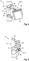
- eine schematische Draufsicht mit einem seitlich verschwenkten Wickeltisch in einer Ablageposition; und
- Fig. 5:
- eine schematische Darstellung der Rundballenpresse mit einem Wickeltisch in einer Transportposition.
- In
Fig. 1 ist eine Rundballenpresse 10 mit einer in einem Gehäuse 12 angeordneten Presskammer 14 zum Pressen von Rundballen 16 in einer schematischen Seitenansicht dargestellt. Die Rundballenpresse 10 ist in Form einer Festkammerpresse ausgebildet, kann aber alternativ auch in Form einer Rundballenpresse 10 mit einer variablen Presskammer ausgebildet sein. Die Rundballenpresse 10 kann mit einer landwirtschaftlichen Arbeitsmaschine als Zugfahrzeug (nicht dargestellt) zum Fortbewegen und Versorgen mit Antriebsenergie verbunden werden. Die Rundballenpresse 10 dient üblicherweise dem Aufnehmen und Verdichten von Erntegut, welches über einen Rotor 28 durch eine Zuführöffnung 30 in die Presskammer 14 geleitet und dort verdichtet wird. Die dargestellte Presse weist eine Presskammer 14 auf, entlang deren Umfang Pressrollen 18 angeordnet sind, wobei benachbart zu der Zuführöffnung gehäusefeste Pressrollen 20 angeordnet sind, welche auch bei einem Auswerfen des Rundballens 16 nicht verlagert werden. Ein Teil der Pressrollen 18 ist zusammen mit einem hinteren Teil des Gehäuses 12 verschwenkbar ausgebildet, damit ein fertig gepresster Rundballen 16 aus der Presskammer 14 ausgeworden und einer der Presskammer 14 nachgeordneten Wickelvorrichtung 22 zugeführt werden kann. Die Wickelvorrichtung 22 dient dazu, einen Rundballen 16 mit einem Wickelmaterial 26 wie einer Folie zu umwickeln, beispielsweise um das Erntegut als Tierfutter zu silieren. Das Wickelmaterial 26 wird dabei in Rollen vorgehalten. Der Rundballen 16 wird dabei üblicherweise auf einem Wickeltisch 24 abgelegt, welcher den Rundballen 16 zumindest um seine Geometrieachse drehen kann, um ein gleichmäßiges Umwickeln mit dem Wickelmaterial 26 zu gewährleisten. Die dargestellte Rundballenpresse 10 weist eine heckseitig geöffnete Presskammer 14 auf, wobei ein hinterer Teil des Gehäuses 12 mit den dort angeordneten Pressrollen 18 nach oben verschwenkt ist und so ein entnehmen des Rundballens 16 aus der Presskammer 14 ermöglicht. - Gemäß der Erfindung ist der dargestellte Wickeltisch 24 mit einem Ladearm 32 an dem Gehäuse 12 der Rundballenpresse 10 angeordnet. Der Wickeltisch 24 kann dadurch aus der dargestellten Ladeposition L im Wesentlichen linear zu einer Längsrichtung der Presse 10 in eine Wickelposition W verlagert werden. In der dargestellten Ladeposition L ist der Wickeltisch 24 bei geöffneter Presskammer 14 an einer gehäusefesten Pressroll 20 angeordnet, welche bodenseitig der Presskammer 14 und benachbart zu der Zuführöffnung 30 angeordnet ist. Der Rundballen 16 ist zumindest teilweise durch Einfluß der Schwerkraft aus der geöffneten Presskammer 14 auf den Wickeltisch 24 gelangt.
- Der Wickeltisch 24 ist über den Ladearm 32 mit dem Gehäuse 12 der Presse schwenkbar verbunden. Der Ladearm 32 ist dabei mit einem Rahmen 34 des Gehäuses 12 benachbart zu einer Radachse 36 verbunden. Der Ladearm 32 ist in Form eines Knickarmes ausgebildet und weist einen ersten Ausleger 38 und einen zweiten Ausleger 40 auf, welche über ein Knickgelenk 54 verschwenkbar miteinander verbunden sind. Der erste Ausleger 38 ist dabei mit dem Gehäuse 12, insbesondere dem Rahmen 34, und der zweite Ausleger 40 mit dem Wickeltisch 24 verbunden. Der Ladearm 32 ist gehäuseseitig um eine erste Schwenkachse 42 und in dem Knickgelenk 54 um eine zweite Schwenkachse 44 verschwenkbar, wobei die erste und zweite Schwenkachse 42, 44 im Wesentlichen parallel angeordnet sind, wodurch der Ladearm 32 im Wesentlichen in einer Ebene verschwenkt werden kann. Endseitig des Ladearmes 32 oder des zweiten Auslegers 40 ist der Wickeltisch 24 zumindest um eine Rotationsachse 46 drehbar angeordnet. Die Rotationsachse 46, die erste Schwenkachse 42 und/oder zweite Schwenkachse 44 können parallel angeordnet sein, wodurch ein Verschwenken des Ladearmes 32 und des Wickeltisches 24 im Wesentlichen in einer Ebene ermöglicht wird. Endseitig des zweiten Auslegers 40 der Wickeltisch 24 ist mittels eines Drehgelenks um eine Drehachse 48 drehbar. Die Drehachse 48 ist dabei parallel, insbesondere koaxial, zu dem zweiten Ausleger 40 angeordnet. Um den Wickeltisch 24 in die dargestellte Ladeposition L zur Aufnahme des Rundballens 16 verbringen zu können, ist der Ladearm 32 um eine Kippachse 50 herum in der Vertikalen kippbar ausgestaltet. Die Kippachse 50 ist dabei im Wesentlichen parallel zur Radachse 36 angeordnet.
- Der Ladearm 32 ist an einer Seite des Rahmens 34 angeordnet, um über das Knickgelenk 54 eine im Wesentlichen lineare Bewegung des Wickeltisches 24 zu ermöglichen. Eine Steuerung der Bewegung des Ladearmes 32, des Wickeltisches 24 und/oder der Wickelvorrichtung 22 erfolgt über eine Steuerungsvorrichtung 52, welche pressenseitig installiert ist. Die Steuerungsvorrichtung 52 steuert dabei die zur Erreichung einer bestimmten Position notwendigen Bewegungen des Ladearmes 32.
- Das Wickelmaterial 26 (
Fig. 2 ) zum Umhüllen des Rundballens 16 ist heckseitig an dem Gehäuse 12 der Presse 10 in Form von mindestens einer Rolle angeordnet. Der Ladearm 32 ist in im Wesentlichen horizontaler Richtung nach hinten verschwenkt, wodurch der Wickeltisch 24 mit dem Rundballen 16 hinter der geschlossenen Presskammer 14 in eine Wickelposition W verbracht wurde. Das Wickelmaterial 26 umspannt den Rundballen 16, wobei der Rundballen 16 durch den Wickeltisch 26 ebenfalls in Rotation versetzt werden kann, wodurch eine vollständige Umwickelung des Rundballens 16 mit dem Wickelmaterial 24 gewährleistet werden kann. Der Ladearm 32 ist dabei in eine im Wesentlichen waagerechte Position um seine Kippachse 50 verkippt, wobei die erste und zweite Schwenkachse 42, 44 und die Rotationsachse 46 des Wickeltisches 24 im Wesentlichen parallel angeordnet sind, so dass der Ladearm 32 im Wesentlichen in einer Ebene verschwenkt ist. Nach dem Umwickeln des Rundballens 16 mit dem Wickelmaterial 26 ist der Wickeltisch 24 in die Ablageposition A verbracht (Fig. 3 ), in der, beispielsweise unter Berücksichtigung der geographischen Randbedingungen, die Ablage des Rundballens 16 auf den Boden erfolgt. Der Ladearm 32 ist außermittig an dem Gehäuse 12 bzw. dem Rahmen 34 befestigt, und außenseitig benachbart an einem der Räder angeordnet. Aufgrund der außermittigen Anordnung ist der Ladearm 32 in der dargestellten Ablageposition A leicht in dem Knickgelenk 54 zur Mitte hin geknickt, so dass mittels einer Drehung um die Drehachse 48 der Wickeltisch 24 so weit nach hinten gekippt werden kann, dass der Rundballen 16 auf dem Boden abgelegt werden kann. Hierbei ist auch eine, wie inFigur 4 dargestellt, seitliche Ablage des Rundballens 16 möglich, welche besonders in hügeligem Gelände ein Weggrollen des Rundballen 16 vermeiden hilft. Denkbar ist auch eine Ablageposition A des Wickeltisches 24, in ein Rundballen auf einer seiner Stirnseiten abgelegt werden kann. Hierdurch kann bei besonders hügeligem Gelände ein sicheres Ablegen und ein Wegrollen des Ballens 16 vermieden werden. Der Ladearm 32 ist mit dem ersten Ausleger 38 rechts unterhalb der Presskammer 14, benachbart zu dem in Fahrtrichtung der Presse 10 gesehenen Bereich des Rahmens 34, derart angeordnet, dass der Ladearm 32 und insbesondere der erste Ausleger 38, um die erste Schwenkachse 42 und die Kippachse 50 herum bewegbar sind. - In der in
Figur 5 dargestellten Transportposition T ist der Wickeltisch 24 mittels des Ladearms 32 weitestgehend nach innen und unterhalb der Presskammer 14 verschwenkt. Zudem ist der Wickeltisch 24 über ein Verkippen des Ladearmes 32 in vertikaler Richtung unmittelbar benachbart an die Presskammer 14 herangeklappt. Der Wickeltisch 24 ragt dabei nicht über die beiderseitig des Gehäuses 12 angeordneten Rollen des Wickelmaterials 26 hinaus und ragt heckseitig nicht über die Presse 10 hinaus. -
- 10
- Rundballenpresse
- 12
- Gehäuse
- 14
- Presskammer
- 16
- Rundballen
- 18
- Pressrolle
- 20
- gehäusefeste Pressrolle
- 22
- Wickelvorrichtung
- 24
- Wickeltisch
- 26
- Wickelmaterial
- 28
- Rotor
- 30
- Zufuhröffnung
- 32
- Ladearm
- 34
- Rahmen
- 36
- Radachse
- 38
- erster Ausleger
- 40
- zweiter Ausleger
- 42
- erste Schwenkachse
- 44
- zweite Schwenkachse
- 46
- Rotationsachse
- 48
- Drehachse
- 50
- Kippachse
- 52
- Steuerungsvorrichtung
- 54
- Knickgelenk
- L
- Ladeposition
- W
- Wickelposition
- A
- Ablageposition
- T
- Transportposition
Claims (10)
- Rundballenpresse mit einer in einem Gehäuse (12) angeordneten Presskammer (14) zum Pressen von Rundballen (16), welche in einem unteren Bereich zumindest eine im Wesentlichen gehäusefeste Pressrolle (20) aufweist, und einer der Presskammer (14) nachgelagerten Wickelvorrichtung (22) mit einem Wickeltisch (24) zum Umwickeln eines Rundballens (16) mit einem Wickelmaterial (26), dadurch gekennzeichnet, dass der Wickeltisch (24) mittels eines Ladearmes (32) beweglich an dem Gehäuse (12) angeordnet ist, und zwischen zumindest einer Ladeposition (L) zum Aufnehmen eines Ballens (16) aus der Presskammer (14) und einer Wickelposition (W) zum Umwickeln des Ballens (16) verlagerbar ausgebildet ist.
- Rundballenpresse nach Anspruch 1, dadurch gekennzeichnet, dass der Ladearm (32) pressenseitig um eine erste Schwenkachse (42) verschwenkbar gelagert ist und mindestens einen ersten Ausleger (38) und einen zweiten Ausleger (40) aufweist, welche über ein Knickgelenk (54) um eine zweite Schwenkachse (44) verschwenkbar verbunden sind.
- Rundballenpresse nach Anspruch 1 oder 2, dadurch gekennzeichnet, dass der Wickeltisch (24) endseitig des Ladearmes (32) um eine Rotationsachse (46) drehbar, und insbesondere um eine Drehachse (48) herum rotierbar, ausgebildet ist.
- Rundballenpresse nach einem der vorherigen Ansprüche, dadurch gekennzeichnet, dass der Ladearm (32) pressenseitig um eine im Wesentlichen waagerechte Kippachse (50) in vertikaler Richtung kippbar ausgestaltet ist.
- Rundballenpresse nach einem der vorherigen Ansprüche, dadurch gekennzeichnet, dass ein Dämpfungsmittel zur Dämpfung einer Bewegung des Ladearmes (32) um die Kippachse (50), insbesondere zwischen Gehäuse (12) und erstem Ausleger (38), vorgesehen ist.
- Rundballenpresse nach einem der vorherigen Ansprüche, dadurch gekennzeichnet, dass in der Ladeposition (L) der Wickeltisch (24) im Wesentlichen unterhalb der Presskammer (14) und benachbart zu der mindestens einen gehäusefesten Pressrolle (20) angeordnet ist.
- Rundballenpresse nach einem der vorherigen Ansprüche, dadurch gekennzeichnet, dass mindestens eine Rolle (26) des Wickelmaterials gehäusefest zum Umwickeln eines Rundballens (16) an dem Gehäuse (12) angeordnet ist.
- Rundballenpresse nach einem der vorherigen Ansprüche, dadurch gekennzeichnet, dass der Wickeltisch (24) mittels des Ladearms (32) in eine Transportposition (T), in welcher der Wickeltisch (24) benachbart zu der Presskammer (14) angeordnet ist und/oder in eine Ablageposition (A) verbringbar ist, in welcher ein Rundballen (16) von dem Wickeltisch (24) umfangsseitig oder stirnseitig auf den Boden ablegbar ist.
- Rundballenpresse nach einem der vorherigen Ansprüche, dadurch gekennzeichnet, dass zur Steuerung des Ladearms (32), des Wickeltisches (24) und/oder der Wickelvorrichtung (22), insbesondere zur Verlagerung des Wickeltisches (24) in eine Ladeposition (L), eine Wickelposition (W), eine Transportposition (T) und/oder eine Ablageposition (A), eine Steuerungsvorrichtung (52) vorgesehen.
- Rundballenpresse nach einem der vorherigen Ansprüche, dadurch gekennzeichnet, dass mindestens ein Aktor zur Bewegung des Ladearmes (32) und/oder des Wickeltisches (24) vorgesehen ist, welcher ein hydraulischer, pneumatischer und/oder elektrischer Aktor ist.
Applications Claiming Priority (1)
| Application Number | Priority Date | Filing Date | Title |
|---|---|---|---|
| DE102018110035.3A DE102018110035A1 (de) | 2018-04-26 | 2018-04-26 | Rundballenpresse |
Publications (2)
| Publication Number | Publication Date |
|---|---|
| EP3560322A1 true EP3560322A1 (de) | 2019-10-30 |
| EP3560322B1 EP3560322B1 (de) | 2022-01-05 |
Family
ID=65351883
Family Applications (1)
| Application Number | Title | Priority Date | Filing Date |
|---|---|---|---|
| EP19155637.2A Active EP3560322B1 (de) | 2018-04-26 | 2019-02-06 | Rundballenpresse |
Country Status (2)
| Country | Link |
|---|---|
| EP (1) | EP3560322B1 (de) |
| DE (1) | DE102018110035A1 (de) |
Citations (6)
| Publication number | Priority date | Publication date | Assignee | Title |
|---|---|---|---|---|
| EP1048201A1 (de) * | 1999-04-28 | 2000-11-02 | Deere & Company | Ballenwickelgerät |
| EP1266562A1 (de) * | 2001-06-11 | 2002-12-18 | Lely Enterprises AG | Rundballenpresse für landwirtschaftliche Halmgüter |
| US20060075552A1 (en) * | 2004-10-07 | 2006-04-13 | Mark Diggins | Invalid hoist with safety device |
| EP2050330A1 (de) | 2007-10-19 | 2009-04-22 | Usines CLAAS France S.A.S. | Ballenwickler zur Wicklung runder Ballen |
| DE102013108246A1 (de) * | 2013-08-01 | 2015-02-05 | Usines Claas France S.A.S. | Landwirtschaftliche Rundballenpresse |
| WO2017213492A1 (en) * | 2016-06-07 | 2017-12-14 | Forage Company B.V. | Baler-wrapper combination with a moveable bale support and bale forming and wrapping method using such a combination |
-
2018
- 2018-04-26 DE DE102018110035.3A patent/DE102018110035A1/de not_active Withdrawn
-
2019
- 2019-02-06 EP EP19155637.2A patent/EP3560322B1/de active Active
Patent Citations (6)
| Publication number | Priority date | Publication date | Assignee | Title |
|---|---|---|---|---|
| EP1048201A1 (de) * | 1999-04-28 | 2000-11-02 | Deere & Company | Ballenwickelgerät |
| EP1266562A1 (de) * | 2001-06-11 | 2002-12-18 | Lely Enterprises AG | Rundballenpresse für landwirtschaftliche Halmgüter |
| US20060075552A1 (en) * | 2004-10-07 | 2006-04-13 | Mark Diggins | Invalid hoist with safety device |
| EP2050330A1 (de) | 2007-10-19 | 2009-04-22 | Usines CLAAS France S.A.S. | Ballenwickler zur Wicklung runder Ballen |
| DE102013108246A1 (de) * | 2013-08-01 | 2015-02-05 | Usines Claas France S.A.S. | Landwirtschaftliche Rundballenpresse |
| WO2017213492A1 (en) * | 2016-06-07 | 2017-12-14 | Forage Company B.V. | Baler-wrapper combination with a moveable bale support and bale forming and wrapping method using such a combination |
Also Published As
| Publication number | Publication date |
|---|---|
| EP3560322B1 (de) | 2022-01-05 |
| DE102018110035A1 (de) | 2019-10-31 |
Similar Documents
| Publication | Publication Date | Title |
|---|---|---|
| DE60225537T2 (de) | Ballenpresse | |
| EP3578035B1 (de) | Rundballenpresse und entladeverfahren | |
| EP3785521B1 (de) | Landwirtschaftliche ballenpresse mit einer bindung und verfahren zum warten der ballenpresse | |
| EP2878190B1 (de) | Landwirtschaftliche Rundballenpresse | |
| DE19932336A1 (de) | Kontinuierlich arbeitende Rundballenpresse | |
| EP2606715B1 (de) | Press-Wickelkombination | |
| EP2022319B1 (de) | Landwirtschaftliche Ballenpresse | |
| EP3721699A1 (de) | Ballenwickelvorrichtung für eine ballenpresse, beladehilfe und ballenpresse | |
| EP2984922B1 (de) | Ballenwickeleinrichtung | |
| EP1726204B1 (de) | Vorrichtung zum Pressen und Umhüllen von Rundballen | |
| EP3143868B1 (de) | Rundballenpresse | |
| EP3560323B1 (de) | Landwirtschaftliche rundballenpresse und verfahren zum betrieb einer landwirtschaftlichen rundballenpresse | |
| EP2647281B1 (de) | Rundballenpresse | |
| EP3338534B1 (de) | Rundballenpresse | |
| EP3560322B1 (de) | Rundballenpresse | |
| DE2219976A1 (de) | Ladewagen | |
| DE29911916U1 (de) | Wickelvorrichtung und System zum Pressen und Wickeln von Ballen | |
| EP3760031B1 (de) | Rundballenpresse und verfahren zum betrieb einer rundballenpresse | |
| EP4176705A1 (de) | Rundballenpresse mit einer vorrichtung zum klemmen eines ballens | |
| DE102011109890B4 (de) | Landwirtschaftliche Rundballenpresse | |
| EP3275305B1 (de) | Ballenpresse mit wickelvorrichtung | |
| EP4183244A1 (de) | Rundballenpresse | |
| EP2853145B1 (de) | Rundballenpresse | |
| DE2536793C3 (de) | Vorrichtung zum Abtragen, Transportieren und Austeilen von Silagefutter aus Fahrsilos, Mieten o.dgl. (sog.Silofräse) | |
| EP4282250B1 (de) | Rundballenpresse |
Legal Events
| Date | Code | Title | Description |
|---|---|---|---|
| PUAI | Public reference made under article 153(3) epc to a published international application that has entered the european phase |
Free format text: ORIGINAL CODE: 0009012 |
|
| STAA | Information on the status of an ep patent application or granted ep patent |
Free format text: STATUS: THE APPLICATION HAS BEEN PUBLISHED |
|
| AK | Designated contracting states |
Kind code of ref document: A1 Designated state(s): AL AT BE BG CH CY CZ DE DK EE ES FI FR GB GR HR HU IE IS IT LI LT LU LV MC MK MT NL NO PL PT RO RS SE SI SK SM TR |
|
| AX | Request for extension of the european patent |
Extension state: BA ME |
|
| STAA | Information on the status of an ep patent application or granted ep patent |
Free format text: STATUS: REQUEST FOR EXAMINATION WAS MADE |
|
| 17P | Request for examination filed |
Effective date: 20200430 |
|
| RBV | Designated contracting states (corrected) |
Designated state(s): AL AT BE BG CH CY CZ DE DK EE ES FI FR GB GR HR HU IE IS IT LI LT LU LV MC MK MT NL NO PL PT RO RS SE SI SK SM TR |
|
| STAA | Information on the status of an ep patent application or granted ep patent |
Free format text: STATUS: EXAMINATION IS IN PROGRESS |
|
| 17Q | First examination report despatched |
Effective date: 20201014 |
|
| GRAP | Despatch of communication of intention to grant a patent |
Free format text: ORIGINAL CODE: EPIDOSNIGR1 |
|
| STAA | Information on the status of an ep patent application or granted ep patent |
Free format text: STATUS: GRANT OF PATENT IS INTENDED |
|
| INTG | Intention to grant announced |
Effective date: 20210811 |
|
| GRAS | Grant fee paid |
Free format text: ORIGINAL CODE: EPIDOSNIGR3 |
|
| GRAA | (expected) grant |
Free format text: ORIGINAL CODE: 0009210 |
|
| STAA | Information on the status of an ep patent application or granted ep patent |
Free format text: STATUS: THE PATENT HAS BEEN GRANTED |
|
| AK | Designated contracting states |
Kind code of ref document: B1 Designated state(s): AL AT BE BG CH CY CZ DE DK EE ES FI FR GB GR HR HU IE IS IT LI LT LU LV MC MK MT NL NO PL PT RO RS SE SI SK SM TR |
|
| REG | Reference to a national code |
Ref country code: GB Ref legal event code: FG4D Free format text: NOT ENGLISH |
|
| REG | Reference to a national code |
Ref country code: CH Ref legal event code: EP |
|
| REG | Reference to a national code |
Ref country code: AT Ref legal event code: REF Ref document number: 1459699 Country of ref document: AT Kind code of ref document: T Effective date: 20220115 |
|
| REG | Reference to a national code |
Ref country code: DE Ref legal event code: R096 Ref document number: 502019003131 Country of ref document: DE |
|
| REG | Reference to a national code |
Ref country code: IE Ref legal event code: FG4D Free format text: LANGUAGE OF EP DOCUMENT: GERMAN |
|
| REG | Reference to a national code |
Ref country code: LT Ref legal event code: MG9D |
|
| REG | Reference to a national code |
Ref country code: NL Ref legal event code: MP Effective date: 20220105 |
|
| PG25 | Lapsed in a contracting state [announced via postgrant information from national office to epo] |
Ref country code: NL Free format text: LAPSE BECAUSE OF FAILURE TO SUBMIT A TRANSLATION OF THE DESCRIPTION OR TO PAY THE FEE WITHIN THE PRESCRIBED TIME-LIMIT Effective date: 20220105 |
|
| PG25 | Lapsed in a contracting state [announced via postgrant information from national office to epo] |
Ref country code: SE Free format text: LAPSE BECAUSE OF FAILURE TO SUBMIT A TRANSLATION OF THE DESCRIPTION OR TO PAY THE FEE WITHIN THE PRESCRIBED TIME-LIMIT Effective date: 20220105 Ref country code: RS Free format text: LAPSE BECAUSE OF FAILURE TO SUBMIT A TRANSLATION OF THE DESCRIPTION OR TO PAY THE FEE WITHIN THE PRESCRIBED TIME-LIMIT Effective date: 20220105 Ref country code: PT Free format text: LAPSE BECAUSE OF FAILURE TO SUBMIT A TRANSLATION OF THE DESCRIPTION OR TO PAY THE FEE WITHIN THE PRESCRIBED TIME-LIMIT Effective date: 20220505 Ref country code: NO Free format text: LAPSE BECAUSE OF FAILURE TO SUBMIT A TRANSLATION OF THE DESCRIPTION OR TO PAY THE FEE WITHIN THE PRESCRIBED TIME-LIMIT Effective date: 20220405 Ref country code: LT Free format text: LAPSE BECAUSE OF FAILURE TO SUBMIT A TRANSLATION OF THE DESCRIPTION OR TO PAY THE FEE WITHIN THE PRESCRIBED TIME-LIMIT Effective date: 20220105 Ref country code: HR Free format text: LAPSE BECAUSE OF FAILURE TO SUBMIT A TRANSLATION OF THE DESCRIPTION OR TO PAY THE FEE WITHIN THE PRESCRIBED TIME-LIMIT Effective date: 20220105 Ref country code: ES Free format text: LAPSE BECAUSE OF FAILURE TO SUBMIT A TRANSLATION OF THE DESCRIPTION OR TO PAY THE FEE WITHIN THE PRESCRIBED TIME-LIMIT Effective date: 20220105 Ref country code: BG Free format text: LAPSE BECAUSE OF FAILURE TO SUBMIT A TRANSLATION OF THE DESCRIPTION OR TO PAY THE FEE WITHIN THE PRESCRIBED TIME-LIMIT Effective date: 20220405 |
|
| PG25 | Lapsed in a contracting state [announced via postgrant information from national office to epo] |
Ref country code: PL Free format text: LAPSE BECAUSE OF FAILURE TO SUBMIT A TRANSLATION OF THE DESCRIPTION OR TO PAY THE FEE WITHIN THE PRESCRIBED TIME-LIMIT Effective date: 20220105 Ref country code: LV Free format text: LAPSE BECAUSE OF FAILURE TO SUBMIT A TRANSLATION OF THE DESCRIPTION OR TO PAY THE FEE WITHIN THE PRESCRIBED TIME-LIMIT Effective date: 20220105 Ref country code: GR Free format text: LAPSE BECAUSE OF FAILURE TO SUBMIT A TRANSLATION OF THE DESCRIPTION OR TO PAY THE FEE WITHIN THE PRESCRIBED TIME-LIMIT Effective date: 20220406 Ref country code: FI Free format text: LAPSE BECAUSE OF FAILURE TO SUBMIT A TRANSLATION OF THE DESCRIPTION OR TO PAY THE FEE WITHIN THE PRESCRIBED TIME-LIMIT Effective date: 20220105 |
|
| PG25 | Lapsed in a contracting state [announced via postgrant information from national office to epo] |
Ref country code: IS Free format text: LAPSE BECAUSE OF FAILURE TO SUBMIT A TRANSLATION OF THE DESCRIPTION OR TO PAY THE FEE WITHIN THE PRESCRIBED TIME-LIMIT Effective date: 20220505 |
|
| REG | Reference to a national code |
Ref country code: DE Ref legal event code: R097 Ref document number: 502019003131 Country of ref document: DE |
|
| REG | Reference to a national code |
Ref country code: CH Ref legal event code: PL |
|
| PG25 | Lapsed in a contracting state [announced via postgrant information from national office to epo] |
Ref country code: SM Free format text: LAPSE BECAUSE OF FAILURE TO SUBMIT A TRANSLATION OF THE DESCRIPTION OR TO PAY THE FEE WITHIN THE PRESCRIBED TIME-LIMIT Effective date: 20220105 Ref country code: SK Free format text: LAPSE BECAUSE OF FAILURE TO SUBMIT A TRANSLATION OF THE DESCRIPTION OR TO PAY THE FEE WITHIN THE PRESCRIBED TIME-LIMIT Effective date: 20220105 Ref country code: RO Free format text: LAPSE BECAUSE OF FAILURE TO SUBMIT A TRANSLATION OF THE DESCRIPTION OR TO PAY THE FEE WITHIN THE PRESCRIBED TIME-LIMIT Effective date: 20220105 Ref country code: MC Free format text: LAPSE BECAUSE OF FAILURE TO SUBMIT A TRANSLATION OF THE DESCRIPTION OR TO PAY THE FEE WITHIN THE PRESCRIBED TIME-LIMIT Effective date: 20220105 Ref country code: LU Free format text: LAPSE BECAUSE OF NON-PAYMENT OF DUE FEES Effective date: 20220206 Ref country code: EE Free format text: LAPSE BECAUSE OF FAILURE TO SUBMIT A TRANSLATION OF THE DESCRIPTION OR TO PAY THE FEE WITHIN THE PRESCRIBED TIME-LIMIT Effective date: 20220105 Ref country code: DK Free format text: LAPSE BECAUSE OF FAILURE TO SUBMIT A TRANSLATION OF THE DESCRIPTION OR TO PAY THE FEE WITHIN THE PRESCRIBED TIME-LIMIT Effective date: 20220105 Ref country code: CZ Free format text: LAPSE BECAUSE OF FAILURE TO SUBMIT A TRANSLATION OF THE DESCRIPTION OR TO PAY THE FEE WITHIN THE PRESCRIBED TIME-LIMIT Effective date: 20220105 |
|
| PLBE | No opposition filed within time limit |
Free format text: ORIGINAL CODE: 0009261 |
|
| STAA | Information on the status of an ep patent application or granted ep patent |
Free format text: STATUS: NO OPPOSITION FILED WITHIN TIME LIMIT |
|
| PG25 | Lapsed in a contracting state [announced via postgrant information from national office to epo] |
Ref country code: AL Free format text: LAPSE BECAUSE OF FAILURE TO SUBMIT A TRANSLATION OF THE DESCRIPTION OR TO PAY THE FEE WITHIN THE PRESCRIBED TIME-LIMIT Effective date: 20220105 |
|
| 26N | No opposition filed |
Effective date: 20221006 |
|
| PG25 | Lapsed in a contracting state [announced via postgrant information from national office to epo] |
Ref country code: LI Free format text: LAPSE BECAUSE OF NON-PAYMENT OF DUE FEES Effective date: 20220228 Ref country code: IE Free format text: LAPSE BECAUSE OF NON-PAYMENT OF DUE FEES Effective date: 20220206 Ref country code: CH Free format text: LAPSE BECAUSE OF NON-PAYMENT OF DUE FEES Effective date: 20220228 |
|
| PG25 | Lapsed in a contracting state [announced via postgrant information from national office to epo] |
Ref country code: SI Free format text: LAPSE BECAUSE OF FAILURE TO SUBMIT A TRANSLATION OF THE DESCRIPTION OR TO PAY THE FEE WITHIN THE PRESCRIBED TIME-LIMIT Effective date: 20220105 |
|
| P01 | Opt-out of the competence of the unified patent court (upc) registered |
Effective date: 20230516 |
|
| PG25 | Lapsed in a contracting state [announced via postgrant information from national office to epo] |
Ref country code: IT Free format text: LAPSE BECAUSE OF FAILURE TO SUBMIT A TRANSLATION OF THE DESCRIPTION OR TO PAY THE FEE WITHIN THE PRESCRIBED TIME-LIMIT Effective date: 20220105 |
|
| GBPC | Gb: european patent ceased through non-payment of renewal fee |
Effective date: 20230206 |
|
| PG25 | Lapsed in a contracting state [announced via postgrant information from national office to epo] |
Ref country code: GB Free format text: LAPSE BECAUSE OF NON-PAYMENT OF DUE FEES Effective date: 20230206 |
|
| PG25 | Lapsed in a contracting state [announced via postgrant information from national office to epo] |
Ref country code: GB Free format text: LAPSE BECAUSE OF NON-PAYMENT OF DUE FEES Effective date: 20230206 |
|
| PG25 | Lapsed in a contracting state [announced via postgrant information from national office to epo] |
Ref country code: MK Free format text: LAPSE BECAUSE OF FAILURE TO SUBMIT A TRANSLATION OF THE DESCRIPTION OR TO PAY THE FEE WITHIN THE PRESCRIBED TIME-LIMIT Effective date: 20220105 Ref country code: CY Free format text: LAPSE BECAUSE OF FAILURE TO SUBMIT A TRANSLATION OF THE DESCRIPTION OR TO PAY THE FEE WITHIN THE PRESCRIBED TIME-LIMIT Effective date: 20220105 |
|
| PG25 | Lapsed in a contracting state [announced via postgrant information from national office to epo] |
Ref country code: HU Free format text: LAPSE BECAUSE OF FAILURE TO SUBMIT A TRANSLATION OF THE DESCRIPTION OR TO PAY THE FEE WITHIN THE PRESCRIBED TIME-LIMIT; INVALID AB INITIO Effective date: 20190206 |
|
| PG25 | Lapsed in a contracting state [announced via postgrant information from national office to epo] |
Ref country code: TR Free format text: LAPSE BECAUSE OF FAILURE TO SUBMIT A TRANSLATION OF THE DESCRIPTION OR TO PAY THE FEE WITHIN THE PRESCRIBED TIME-LIMIT Effective date: 20220105 |
|
| PG25 | Lapsed in a contracting state [announced via postgrant information from national office to epo] |
Ref country code: MT Free format text: LAPSE BECAUSE OF FAILURE TO SUBMIT A TRANSLATION OF THE DESCRIPTION OR TO PAY THE FEE WITHIN THE PRESCRIBED TIME-LIMIT Effective date: 20220105 |
|
| REG | Reference to a national code |
Ref country code: AT Ref legal event code: MM01 Ref document number: 1459699 Country of ref document: AT Kind code of ref document: T Effective date: 20240206 |
|
| PG25 | Lapsed in a contracting state [announced via postgrant information from national office to epo] |
Ref country code: AT Free format text: LAPSE BECAUSE OF NON-PAYMENT OF DUE FEES Effective date: 20240206 |
|
| PGFP | Annual fee paid to national office [announced via postgrant information from national office to epo] |
Ref country code: DE Payment date: 20260218 Year of fee payment: 8 |
|
| PGFP | Annual fee paid to national office [announced via postgrant information from national office to epo] |
Ref country code: AT Payment date: 20260410 Year of fee payment: 5 |
|
| PGFP | Annual fee paid to national office [announced via postgrant information from national office to epo] |
Ref country code: BE Payment date: 20260218 Year of fee payment: 8 |
|
| PGFP | Annual fee paid to national office [announced via postgrant information from national office to epo] |
Ref country code: FR Payment date: 20260218 Year of fee payment: 8 |