EP3560263B1 - Traffic-priority based silencing techniques for interference mitigation - Google Patents
Traffic-priority based silencing techniques for interference mitigation Download PDFInfo
- Publication number
- EP3560263B1 EP3560263B1 EP17808295.4A EP17808295A EP3560263B1 EP 3560263 B1 EP3560263 B1 EP 3560263B1 EP 17808295 A EP17808295 A EP 17808295A EP 3560263 B1 EP3560263 B1 EP 3560263B1
- Authority
- EP
- European Patent Office
- Prior art keywords
- resources
- traffic
- semi
- message
- priority
- Prior art date
- Legal status (The legal status is an assumption and is not a legal conclusion. Google has not performed a legal analysis and makes no representation as to the accuracy of the status listed.)
- Active
Links
- 230000030279 gene silencing Effects 0.000 title claims description 172
- 238000000034 method Methods 0.000 title claims description 159
- 230000000116 mitigating effect Effects 0.000 title description 59
- 238000004891 communication Methods 0.000 claims description 342
- 230000005540 biological transmission Effects 0.000 claims description 45
- 230000006870 function Effects 0.000 description 47
- 230000004224 protection Effects 0.000 description 23
- 238000010586 diagram Methods 0.000 description 21
- 238000005516 engineering process Methods 0.000 description 12
- 230000011664 signaling Effects 0.000 description 11
- 230000002093 peripheral effect Effects 0.000 description 7
- 238000012544 monitoring process Methods 0.000 description 6
- 238000013468 resource allocation Methods 0.000 description 6
- 230000008093 supporting effect Effects 0.000 description 5
- 239000000969 carrier Substances 0.000 description 4
- 238000001514 detection method Methods 0.000 description 4
- 230000008569 process Effects 0.000 description 4
- 125000004122 cyclic group Chemical group 0.000 description 3
- 230000003993 interaction Effects 0.000 description 3
- 230000003287 optical effect Effects 0.000 description 3
- 238000012545 processing Methods 0.000 description 3
- 230000001360 synchronised effect Effects 0.000 description 3
- 238000003491 array Methods 0.000 description 2
- 239000000835 fiber Substances 0.000 description 2
- 238000007726 management method Methods 0.000 description 2
- 238000010295 mobile communication Methods 0.000 description 2
- 230000008520 organization Effects 0.000 description 2
- 239000002245 particle Substances 0.000 description 2
- 230000000737 periodic effect Effects 0.000 description 2
- 238000001228 spectrum Methods 0.000 description 2
- 238000012546 transfer Methods 0.000 description 2
- 230000003190 augmentative effect Effects 0.000 description 1
- 230000006399 behavior Effects 0.000 description 1
- 230000001413 cellular effect Effects 0.000 description 1
- 239000003795 chemical substances by application Substances 0.000 description 1
- 238000004590 computer program Methods 0.000 description 1
- 230000001419 dependent effect Effects 0.000 description 1
- 230000001066 destructive effect Effects 0.000 description 1
- 230000009977 dual effect Effects 0.000 description 1
- 230000007613 environmental effect Effects 0.000 description 1
- 238000001914 filtration Methods 0.000 description 1
- 230000001976 improved effect Effects 0.000 description 1
- 230000000977 initiatory effect Effects 0.000 description 1
- 230000007774 longterm Effects 0.000 description 1
- 238000012986 modification Methods 0.000 description 1
- 230000004048 modification Effects 0.000 description 1
- 230000002085 persistent effect Effects 0.000 description 1
- 230000004044 response Effects 0.000 description 1
- 230000002441 reversible effect Effects 0.000 description 1
- 238000005070 sampling Methods 0.000 description 1
- 208000037918 transfusion-transmitted disease Diseases 0.000 description 1
- 238000012384 transportation and delivery Methods 0.000 description 1
- XLYOFNOQVPJJNP-UHFFFAOYSA-N water Substances O XLYOFNOQVPJJNP-UHFFFAOYSA-N 0.000 description 1
Images


Classifications
-
- H—ELECTRICITY
- H04—ELECTRIC COMMUNICATION TECHNIQUE
- H04W—WIRELESS COMMUNICATION NETWORKS
- H04W72/00—Local resource management
- H04W72/50—Allocation or scheduling criteria for wireless resources
- H04W72/56—Allocation or scheduling criteria for wireless resources based on priority criteria
- H04W72/566—Allocation or scheduling criteria for wireless resources based on priority criteria of the information or information source or recipient
- H04W72/569—Allocation or scheduling criteria for wireless resources based on priority criteria of the information or information source or recipient of the traffic information
-
- H—ELECTRICITY
- H04—ELECTRIC COMMUNICATION TECHNIQUE
- H04W—WIRELESS COMMUNICATION NETWORKS
- H04W48/00—Access restriction; Network selection; Access point selection
- H04W48/16—Discovering, processing access restriction or access information
-
- H—ELECTRICITY
- H04—ELECTRIC COMMUNICATION TECHNIQUE
- H04W—WIRELESS COMMUNICATION NETWORKS
- H04W72/00—Local resource management
- H04W72/20—Control channels or signalling for resource management
- H04W72/23—Control channels or signalling for resource management in the downlink direction of a wireless link, i.e. towards a terminal
-
- H—ELECTRICITY
- H04—ELECTRIC COMMUNICATION TECHNIQUE
- H04W—WIRELESS COMMUNICATION NETWORKS
- H04W76/00—Connection management
- H04W76/10—Connection setup
- H04W76/14—Direct-mode setup
-
- H—ELECTRICITY
- H04—ELECTRIC COMMUNICATION TECHNIQUE
- H04W—WIRELESS COMMUNICATION NETWORKS
- H04W72/00—Local resource management
- H04W72/02—Selection of wireless resources by user or terminal
-
- H—ELECTRICITY
- H04—ELECTRIC COMMUNICATION TECHNIQUE
- H04W—WIRELESS COMMUNICATION NETWORKS
- H04W72/00—Local resource management
- H04W72/20—Control channels or signalling for resource management
-
- H—ELECTRICITY
- H04—ELECTRIC COMMUNICATION TECHNIQUE
- H04W—WIRELESS COMMUNICATION NETWORKS
- H04W72/00—Local resource management
- H04W72/50—Allocation or scheduling criteria for wireless resources
- H04W72/56—Allocation or scheduling criteria for wireless resources based on priority criteria
-
- H—ELECTRICITY
- H04—ELECTRIC COMMUNICATION TECHNIQUE
- H04W—WIRELESS COMMUNICATION NETWORKS
- H04W88/00—Devices specially adapted for wireless communication networks, e.g. terminals, base stations or access point devices
- H04W88/02—Terminal devices
- H04W88/04—Terminal devices adapted for relaying to or from another terminal or user
Description
- The following relates generally to wireless communication, and more specifically to traffic-priority-based silencing techniques for interference mitigation.
- Wireless communications systems are widely deployed to provide various types of communication content such as voice, video, packet data, messaging, broadcast, and so on. These systems may be capable of supporting communication with multiple users by sharing the available system resources (e.g., time, frequency, and power). Examples of such multiple-access systems include code division multiple access (CDMA) systems, time division multiple access (TDMA) systems, frequency division multiple access (FDMA) systems, and orthogonal frequency division multiple access (OFDMA) systems, (e.g., a Long Term Evolution (LTE) system, or a New Radio (NR) system). A wireless multiple-access communications system may include a number of base stations or access network nodes, each simultaneously supporting communication for multiple communication devices, which may be otherwise known as user equipment (UE).
- Multiple types of traffic may be communicated in a wireless communication system. In some cases, different performance metrics of the different types of traffic may cause some types of traffic to have a higher priority than others. One example of a type of traffic in a wireless communication system may include ultra-reliability low-latency communications (URLLC), also sometimes referred to as mission-critical communications, which may specify that packets are communicated with low latency and with high-reliability. URLLC or mission-critical communications may be examples of communications having a high priority, or a priority that is above a threshold. Low priority communications include communications that have a priority that is below a threshold. Examples of communications having a priority level that is less than that of URLLC or mission-critical communications include enhanced mobile broadband (eMBB) communications. A wireless communication system may designate resources to be used for various types of communications, such as high priority or low priority traffic.
- INTERDIGITAL COMMUNICATIONS: "Priority handling for D2D communications" 3GPP DRAFT, 24 MAY 2015 (2015-05-24) relates to group priority in D2D communications. HUAWEI HISILICON: "Discussions on Remaining Issues for SPS" 3GPP DRAFT, 13 November 2016 (2016-11-13) relates to extra latency caused in logical channels having different priorities.
-
WO 2016/047994 A1 relates to methods for solving conflicts between transmissions of different type (e.g., WAN vs D2D, or semi-persistent scheduling "SPS" vs scheduled transmissions) and priority on overlapped subframes; wherein said overlapping of subframes is caused by misalignment of timing advance. In the overlapping region, the transmission with lower priority is pre-empted (i.e. silenced) by the transmitting UE. - The invention is defined by the subject-matter of the independent claims. Particular embodiments of the invention are set out in the dependent claims. The described techniques relate to improved methods, or apparatuses that support traffic-priority-based silencing techniques for interference mitigation. Generally, the described techniques provide priority traffic grant-less access to pre-defined communication resources that are semi-persistently scheduled. A set of semi-persistent communication resources may be reserved for use by priority traffic. If the semi-persistent resources are not used for priority traffic, the semi-persistent resources may be scheduled for use by other types of traffic. As priority traffic is identified, the priority traffic may be transmitted using the semi-persistent resource without having those communication resources granted by a scheduling entity. Such grant-less access to the semi-persistent resources may result in interference between the scheduled traffic and the priority traffic communicated without first scheduling the specific communication resources. To mitigate interference between different traffic types, a UE may transmit a device-to-device silencing message to other UEs. Upon receiving the silencing message, the other UEs may release any scheduled communication resources that at least partially overlap with the semi-persistent resources.
-
-
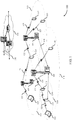
FIG. 1 illustrates an example of a system for wireless communication that supports traffic-priority-based silencing techniques for interference mitigation in accordance with aspects of the present disclosure. -
FIG. 2 illustrates an example of a wireless communication system that supports traffic-priority-based silencing techniques for interference mitigation in accordance with aspects of the present disclosure. -
FIGs. 3A-3C illustrate examples of resource structures that support traffic-priority-based silencing techniques for interference mitigation in accordance with aspects of the present disclosure. -
FIG. 4 illustrates an example of a discovery procedure that supports traffic-priority-based silencing techniques for interference mitigation in accordance with aspects of the present disclosure. -
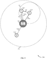
FIG. 5 illustrates an example of a wireless communication system that supports traffic-priority-based silencing techniques for interference mitigation in accordance with aspects of the present disclosure. -
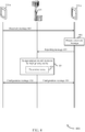
FIG. 6 illustrates an example of a signaling procedure that supports traffic-priority-based silencing techniques for interference mitigation in accordance with aspects of the present disclosure. -
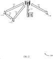
FIG. 7 illustrates an example of a wireless communication system that supports traffic-priority-based silencing techniques for interference mitigation in accordance with aspects of the present disclosure. -
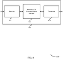
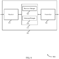
FIGs. 8 through 10 show block diagrams of a device that supports traffic-priority-based silencing techniques for interference mitigation in accordance with aspects of the present disclosure. -
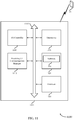
FIG. 11 illustrates a block diagram of a system including a receiving UE that supports traffic-priority-based silencing techniques for interference mitigation in accordance with aspects of the present disclosure. -
FIGs. 12 through 14 show block diagrams of a device that supports traffic-priority-based silencing techniques for interference mitigation in accordance with aspects of the present disclosure. -
FIG. 15 illustrates a block diagram of a system including a transmitting UE that supports traffic-priority-based silencing techniques for interference mitigation in accordance with aspects of the present disclosure. -
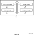
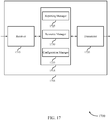
FIGs. 16 through 18 show block diagrams of a device that supports traffic-priority-based silencing techniques for interference mitigation in accordance with aspects of the present disclosure. -
FIG. 19 illustrates a block diagram of a system including a base station that supports traffic-priority-based silencing techniques for interference mitigation in accordance with aspects of the present disclosure. -
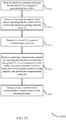
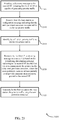
FIGs. 20 through 25 illustrate methods for traffic-priority-based silencing techniques for interference mitigation in accordance with aspects of the present disclosure. - Wireless communication systems may communicate multiple types of traffic having different performance metrics or performance requirements. The different performance metrics of the different types of traffic may have competing aims that do not always work well together. For example, some types of applications may use the wireless communication system for high-throughput applications where large amounts of data are communicated (e.g., downloading a large file). Other types of applications may use the wireless communication system for low-latency applications where the delivery speed of individual packets is a prime consideration (e.g., self-driving vehicles). Such different considerations and performance metrics may, at times, place conflicting demands for use on a wireless communication system.
- Techniques are described herein to provide priority traffic grant-less access to pre-defined communication resources that are semi-persistently scheduled. A set of semi-persistent communication resources may be reserved for use by priority traffic. If the semi-persistent resources are not used for priority traffic, the semi-persistent resources may be scheduled for use by other types of traffic. As priority traffic is identified, the priority traffic may be transmitted using the next available semi-persistent resource without having those communication resources granted by a scheduling entity. Such grant-less access to the semi-persistent resources may result in interference between the scheduled traffic and the priority traffic communicated without first scheduling the specific communication resources. To mitigate interference between different traffic types, a UE may transmit a device-to-device silencing message to other UEs. Upon receiving the silencing message, the other UEs may release any scheduled communication resources that at least partially overlap with the semi-persistent resources.
- By providing priority traffic grant-less access to semi-persistent resources, the priority traffic (e.g., low-latency traffic) may be able to arrive within a time-frame specified by its performance metrics. In addition, use of a device-to-device silencing message allows other types of traffic to use the semi-persistent resources without unduly comprising the priority traffic's ability to arrive at its destination within its performance metrics. In some examples, a discovery procedure may be performed prior to using silencing messages.
- Aspects of the disclosure are initially described in the context of a wireless communications system. Aspects of the disclosure are illustrated by and described with reference to the wireless communication systems, the resources structures, and the process flows that relate to traffic-priority based silencing techniques for interference mitigation. Aspects of the disclosure are further illustrated by and described with reference to apparatus diagrams, system diagrams, and flowcharts that relate to traffic-priority-based silencing techniques for interference mitigation.
-
FIG. 1 illustrates an example of awireless communications system 100 in accordance with various aspects of the present disclosure. Thewireless communications system 100 includesbase stations 105, UEs 115, and acore network 130. In some examples, thewireless communications system 100 may be a LTE (or LTE-Advanced) network, or a New Radio (NR) network. In some cases,wireless communications system 100 may support enhanced broadband communications, ultra-reliable (i.e., mission critical) communications, low latency communications, and communications with low-cost and low-complexity devices. Because these different types of communications have different performance requirements or different performance metrics, in some situations, some of these communications may have priority over other communications. To reduce interference between data and to prevent collisions of data, a UE that transmits priority traffic may first transmit a device-to-device silencing message to other UEs. Upon receiving the silencing message, the other UEs may release any scheduled communication resources that at least partially overlap with the semi-persistent resources. -
Base stations 105 may wirelessly communicate withUEs 115 via one or more base station antennas. Eachbase station 105 may provide communication coverage for a respectivegeographic coverage area 110.Communication links 125 shown inwireless communications system 100 may include uplink (UL) transmissions from aUE 115 to abase station 105, or downlink (DL) transmissions, from abase station 105 to aUE 115. Control information and data may be multiplexed on an uplink channel or downlink according to various techniques. Control information and data may be multiplexed on a downlink channel, for example, using time division multiplexing (TDM) techniques, frequency division multiplexing (FDM) techniques, or hybrid TDM-FDM techniques. In some examples, the control information transmitted during a transmission time interval (TTI) of a downlink channel may be distributed between different control regions in a cascaded manner (e.g., between a common control region and one or more UE-specific control regions). -
UEs 115 may be dispersed throughout thewireless communications system 100, and eachUE 115 may be stationary or mobile. AUE 115 may also be referred to as a mobile station, a subscriber station, a mobile unit, a subscriber unit, a wireless unit, a remote unit, a mobile device, a wireless device, a wireless communications device, a remote device, a mobile subscriber station, an access terminal, a mobile terminal, a wireless terminal, a remote terminal, a handset, a user agent, a mobile client, a client, or some other suitable terminology. AUE 115 may also be a cellular phone, a personal digital assistant (PDA), a wireless modem, a wireless communication device, a handheld device, a tablet computer, a laptop computer, a cordless phone, a personal electronic device, a handheld device, a personal computer, a wireless local loop (WLL) station, an Internet of things (IoT) device, an Internet of Everything (IoE) device, a machine type communication (MTC) device, an appliance, an automobile, or the like. - In some cases, a
UE 115 may also be able to communicate directly with other UEs (e.g., using a peer-to-peer (P2P) or device-to-device (D2D) protocol). One or more of a group ofUEs 115 utilizing D2D communications may be within thecoverage area 110 of a cell.Other UEs 115 in such a group may be outside thecoverage area 110 of a cell, or otherwise unable to receive transmissions from abase station 105. In some cases, groups ofUEs 115 communicating via D2D communications may utilize a one-to-many (1:M) system in which eachUE 115 transmits to everyother UE 115 in the group. In some cases, abase station 105 facilitates the scheduling of resources for D2D communications. In other cases, D2D communications are carried out independent of abase station 105. AUE 115 may transmit a silencing message in a D2D manner to other UEs to clear semi-persistent resources for us by high-priority traffic. - Some
UEs 115, such as MTC or IoT devices, may be low cost or low complexity devices, and may provide for automated communication between machines, i.e., Machine-to-Machine (M2M) communication. M2M or MTC may refer to data communication technologies that allow devices to communicate with one another or a base station without human intervention. For example, M2M or MTC may refer to communications from devices that integrate sensors or meters to measure or capture information and relay that information to a central server or application program that can make use of the information or present the information to humans interacting with the program or application. SomeUEs 115 may be designed to collect information or enable automated behavior of machines. Examples of applications for MTC devices include smart metering, inventory monitoring, water level monitoring, equipment monitoring, healthcare monitoring, wildlife monitoring, weather and geological event monitoring, fleet management and tracking, remote security sensing, physical access control, and transaction-based business charging. In some examples, the mission-critical UEs that transmit silencing messages may be MTC devices. -
Base stations 105 may communicate with thecore network 130 and with one another. For example,base stations 105 may interface with thecore network 130 through backhaul links 132 (e.g., S1, etc.).Base stations 105 may communicate with one another over backhaul links 134 (e.g., X2, etc.) either directly or indirectly (e.g., through core network 130).Base stations 105 may perform radio configuration and scheduling for communication withUEs 115, or may operate under the control of a base station controller (not shown). In some examples,base stations 105 may be macro cells, small cells, hot spots, or the like.Base stations 105 may also be referred to as eNodeBs (eNBs) 105. - A
base station 105 may be connected by an S1 interface to thecore network 130. The core network may be an evolved packet core (EPC), which may include at least one mobility management entity (MME), at least one S-GW, and at least one P-GW. The MME may be the control node that processes the signaling between theUE 115 and the EPC. All user Internet Protocol (IP) packets may be transferred through the S-GW, which itself may be connected to the P-GW. The P-GW may provide IP address allocation as well as other functions. The P-GW may be connected to the network operators IP services. The operators IP services may include the Internet, the Intranet, an IP Multimedia Subsystem (IMS), and a Packet-Switched (PS) Streaming Service (PSS). -
Wireless communications system 100 may operate in an ultra high frequency (UHF) frequency region using frequency bands from 700 MHz to 2600 MHz (2.6 GHz), although in some cases wireless local area networks (WLAN) may use frequencies as high as 4 GHz. This region may also be known as the decimeter band, since the wavelengths range from approximately one decimeter to one meter in length. UHF waves may propagate mainly by line of sight, and may be blocked by buildings and environmental features. However, the waves may penetrate walls sufficiently to provide service to UEs 115 located indoors. Transmission of UHF waves is characterized by smaller antennas and shorter range (e.g., less than 100 km) compared to transmission using the smaller frequencies (and longer waves) of the high frequency (HF) or very high frequency (VHF) portion of the spectrum. In some cases,wireless communications system 100 may also utilize extremely high frequency (EHF) portions of the spectrum (e.g., from 30 GHz to 300 GHz). This region may also be known as the millimeter band, since the wavelengths range from approximately one millimeter to one centimeter in length. Thus, EHF antennas may be even smaller and more closely spaced than UHF antennas. In some cases, this may facilitate use of antenna arrays within a UE 115 (e.g., for directional beamforming). However, EHF transmissions may be subject to even greater atmospheric attenuation and shorter range than UHF transmissions. - Thus,
wireless communications system 100 may support millimeter wave (mmW) communications betweenUEs 115 andbase stations 105. Devices operating in mmW or EHF bands may have multiple antennas to allow beamforming. That is, abase station 105 may use multiple antennas or antenna arrays to conduct beamforming operations for directional communications with aUE 115. Beamforming (which may also be referred to as spatial filtering or directional transmission) is a signal processing technique that may be used at a transmitter (e.g. a base station 105) to shape and/or steer an overall antenna beam in the direction of a target receiver (e.g. a UE 115). This may be achieved by combining elements in an antenna array in such a way that transmitted signals at particular angles experience constructive interference while others experience destructive interference. The silencing messages may also be used when using narrow beams to communicate data. - Time intervals in LTE or NR may be expressed in multiples of a basic time unit (which may be a sampling period of
T s = 1/30,720,000 seconds). Time resources may be organized according to radio frames of length of 10ms (Tf = 307200Ts), which may be identified by a system frame number (SFN) ranging from 0 to 1023. Each frame may include ten one millisecond subframes numbered from zero to nine. A subframe may be further divided into two 0.5 millisecond slots, each of which contains six or seven modulation symbol periods (depending on the length of the cyclic prefix prepended to each symbol). Excluding the cyclic prefix, each symbol contains 2048 sample periods. In some cases the subframe may be the smallest scheduling unit, also known as a TTI. In other cases, a TTI may be shorter than a subframe or may be dynamically selected (e.g., in short TTI bursts or in selected component carriers using short TTIs). - A resource element may consist of one symbol period and one subcarrier (e.g., a 15 KHz frequency range). A resource block may contain 12 consecutive subcarriers in the frequency domain and, for a normal cyclic prefix in each orthogonal frequency division multiplexing (OFDM) symbol, seven consecutive OFDM symbols in the time domain (one slot), or 84 resource elements. The number of bits carried by each resource element may depend on the modulation scheme (the configuration of symbols that may be selected during each symbol period). Thus, the more resource blocks that a UE receives and the higher the modulation scheme, the higher the data rate may be.
-
FIG. 2 illustrates an example of awireless communication system 200 for traffic-priority-based silencing techniques for interference mitigation. Thewireless communication system 200 may support device-to-device (D2D) silencingmessages 220 configured to mitigate interference between high-priority traffic and low-priority traffic. The wireless communication system may include abase station 105, a transmitting UE 115-a, a UE 115-b, and a receiving UE 115-c. The transmitting UE 115-a may be a UE that transmits aD2D silencing message 220 and the receiving UE 115-c may be a UE that receives theD2D silencing message 220. In the some examples, the transmitting UE 115-a may be mission-critical UE capable of generating high-priority traffic and the UEs 115-b, 115-c may be associated with low-priority traffic. The UEs 115-a, 115-b, 115-c may senddata transmissions base station 105 using communication resources that comprise frequency resources and time-based resources. In some scenarios, interference between data transmission may be caused at least in part by multiple types of traffic being communicated using the same communication resources. As used herein, the term "transmitting UE" may refer to a UE that transmits high-priority traffic in a wireless communication system. The term "receiving UE" may refer to any other UE in the wireless communication system and in particular refers to any UE that receives a D2D message from the transmitting UE. In some instances, a receiving UE may be capable of generating high-priority traffic. - Multiple types of traffic may be communicated in the
wireless communication system 200. Different types of traffic may have different performance metrics or requirements. In some cases, the different performance metrics may cause some types of traffic to have a higher priority than others. For example, ultra-reliability low-latency communications (URLLC) may require that packets are communicated with low latency (e.g., within 500 microseconds of detection) and with high-reliability. As such, URLLC traffic may have priority over other types of traffic in thewireless communication system 200. Other types of network traffic may include mobile broadband traffic, enhanced mobile broadband (eMBB) traffic, or machine-to-machine traffic. High-priority traffic (e.g., URLLC traffic) may include network traffic related to a smart electrical grid, industrial automation, augmented reality applications, or may be used in automotive and aviation applications (e.g., self-driving vehicles). Some resource allocation procedures used in a wireless communication system may be unable to satisfy the low-latency and high reliability performance metrics of high-priority traffic. - To satisfy some performance metrics, high-priority traffic may be given grant-less access to certain resources that are semi-persistently scheduled. Grant-less access may refer to a situation where a
UE 115 may use the communication resources without requesting resources from thebase station 105 or receiving a resource grant from thebase station 105. For example, in some cases, rather than requesting resources the UE 115-a may transmit high-priority traffic (e.g., data transmission 205) using the next-available semi-persistent resources. Furthermore, when not being used by high-priority traffic, abase station 105 may schedule the resources to be used by low-priority traffic (e.g.,data transmissions 210 or 215). Grant-less communication, however, may result in collisions between low-priority traffic scheduled to use the semi-persistent resources (e.g., data transmission 210) and the high-priority traffic communicated without first scheduling specific resources (e.g., data transmission 205). If such collisions occur, the high-priority traffic may not arrive at or may not be successfully received by thebase station 105. If the high-priority traffic is not received by thebase station 105, the communication may also fail to satisfy the reliability performance metrics of high-priority traffic. - To mitigate interference, the low-priority traffic that is scheduled to use communication resources that at least partially overlap with semi-persistent resources (e.g., data transmission 210) may be silenced based on a D2D silencing message transmitted by the transmitting UE 115-a. Upon receiving the silencing
message 220, the transmitting UE 115-c may refrain from transmitting its scheduled traffic using the communication resources that at least partially overlap with the semi-persistent resources. As such, the high-priority traffic may therefore be successfully received by thebase station 105 while the scheduled low-priority traffic is not received by the base station. When granting low-priority traffic access to semi-persistent resources, abase station 105 may indicate to the receiving UE 115-c which resources in the grant are semi-persistent resources. - In some instances, the transmitting UE 115-a (capable of generating high-priority traffic) may silence other UEs (e.g., receiving UE 115-c) transmitting low-priority traffic using communication resources that overlap with the semi-persistent resources. The transmitting UE 115-a then may use the released resources for its own high-priority traffic. When the transmitting UE 115-a wants to send high-priority traffic, instead of sending a scheduling request to the
base station 105, the transmitting UE 115-a may transmit a silencingmessage 220 toother UEs 115. The silencingmessage 220 may be a device-to-device communication and may not include any involvement from thebase station 105. Upon receiving the silencingmessage 220, theother UEs 115 may refrain from transmitting low-priority packets using communication resources that at least in partially overlap with semi-persistent resources. The transmitting UE 115-a may transmit its high-priority traffic using the released uplink resources. - To coordinate which communication resources are released and to mitigate which UEs release communication resources, a discovery procedure may be performed. In the discovery procedure, the transmitting UE 115-a may periodically broadcast a discovery message to other UEs in a device-to-device manner. Other UEs may detect the discovery message and report to the
base station 105 what discovery messages were detected. Based on the reporting messages, thebase station 105 may generate one or more zones of protection in its coverage area. Thebase station 105 may also determine a resource pool of semi-persistent resources for each zone of protection. Thebase station 105 may inform theUEs 115 which zone of protection they are in. When the transmitting UE 115-a identifies high-priority data to be transmitted, the transmitting UE 115-a may identify which resources to transmit the high-priority data based on the zones and the resource pools. In addition, other UEs that receive a silencing message from the transmitting UE 115-a, may release resources based on what zone of protection they are in. In this manner, theother UEs 115 may need not release all of their scheduled resources after receiving a silencing message. The transmitting UE 115-a may transmit the high-priority traffic using the semi-persistent resources associated with the zone of protection. In some examples, the silencing message is transmitted using a physical downlink control channel (PDCCH). - As used herein, the term "traffic" may refer to any information moving being communicated between entities in a communication system. For example, traffic may refer to data, packets, communications, messages, indications, signals, or other types of data that may be communicated via a communication system.
- As used herein, the term "high-priority traffic" may refer to data that is able to take precedence over other types of traffic. The term "low-priority traffic" may refer to the other types of traffic that are not able to take precedence. To illustrate the use of the term priority, in some wireless communication systems, all traffic may be treated equally. For example, traffic may be transmitted based on the order that the traffic requested transmission. During heavy traffic periods, however, there may be a delay between a request to transmit data and actual transmission of the data. In some examples, high priority traffic may refer to traffic that is capable of being transmitted before other types of traffic that may have requested the resources first. In some examples, high-priority traffic may be identified based on performance metrics associated with the high-priority traffic. In some instances, the high-priority traffic is low-latency traffic that includes a performance metric indicating that the traffic should be received by its intended recipient within a certain period of time. In some examples, high-priority traffic may be referred to simply as priority traffic of and the low-priority traffic may be referred to as traffic, where the priority traffic has a higher priority than the traffic.
- The
wireless communication system 200 may be an example of thewireless communications system 100 described with reference toFIG. 1 . While only asingle base station 105 and threeUEs 115 are depicted, thewireless communication system 200 may include any number ofbase station 105 and/orUEs 115, among other components. Thebase station 105 may be an example of thebase stations 105 described with reference toFIG. 1 . The UEs 115-a, 115-b, 115-c be examples of theUEs 115 described with reference toFIG. 1 . -
FIG. 3A illustrates an example of aresource structure 300 for traffic-priority-based silencing techniques for interference mitigation. Theresource structure 300 shows an example of a resource allocation procedure of a wireless communication system. Theresource structure 300 may include a number of subframes, such as downlink (DL) subframes 302 and uplink (UL) subframes 304. Thesubframes control portion 306 and adata portion 308. In some examples, thecontrol portion 306 may be PDCCH and thedata portion 308 may be a physical downlink shared channel (PDSCH). TheUL subframes 304 may include acontrol portion 310 of communication resources and adata portion 312 of communication resources. In some examples, thecontrol portion 310 may be a physical uplink control channel (PUCCH) and thedata portion 312 may be a physical uplink shared channel (PUSCH). - Some resource allocation procedures may include: (1) detecting high-priority data to be transmitted, (2) transmitting a scheduling request to a
base station 105 requesting communication resources, (3) receiving a resource grant from the base station, and (4) transmitting the data using the resources indicated by the resource grant. Thus, up to four cycles (e.g., subframes) may occur between the detection of data at a UE 115-a and when the data is transmitted by the UE, which may exceed the performance metrics of certain high-priority traffic. In some cases, such a procedure may take up to ten milliseconds for thebase station 105 to receive the high-priority traffic, much greater than the 500 microseconds associated with some low-latency communications. -
Resource structure 300 illustrates an example of a resource allocation procedure that may occur in the context of resource structures depicted. Attime 320, the UE 115-a (e.g., a UE capable of generating high-priority traffic) may detect or identify data to be transmitted to thebase station 105. In some examples, the data may be high-priority data. The data may be generated at the UE 115-a or it may be received from other network entities in other communications (e.g., a device-to-device communication between UEs or from another base station). - After identifying the data to be transmitted, the UE 115-a may transmit a
scheduling request 322 to thebase station 105 during aUL subframe 304. Thescheduling request 322 may indicate that the UE 115-a has data to be transmitted to thebase station 105. In addition, thescheduling request 322 may indicate characteristics of the data requesting transmission, such as the size of the data, performance metrics associated with the type of data, or combinations thereof. - The
base station 105 may transmit aresource grant 324 to the UE 115-a during aDL subframe 302. Theresource grant 324 may allocate communication resources (e.g., uplink resources) to the UE 115-a to transmit the data. The UE 115-a may transmit thedata 326 to thebase station 105 using the communication resources indicated in theresource grant 324. In some examples, the communication resources included in theresource grant 324 may overlap withsemi-persistent resources 345. - An elapsed
time 330 extends between thedetection time 320 and atransmission time 328 of thedata 326. If thedata 326 was high-priority data, the elapsedtime 330 may be longer than a latency performance metric of thedata 326 requests that the data be transmitted. For example, a latency performance metric of high-priority data may indicate that the high-priority data should be transmitted to its destination within a certain amount of time from detection, for example, 500 microseconds. The elapsedtime 330 associated with scheduling communication resources in the resource allocation procedure may be to 10 milliseconds. To satisfy some performance metrics, high-priority traffic may be given grant-less access to certain resources that are semi-persistently scheduled. -
FIG. 3B illustrates an example of aresource structure 340 for traffic-priority-based silencing techniques for interference mitigation. Theresource structure 340 shows how certain communication resources may be identified assemi-persistent resources 345 reserved for use by high-priority traffic. Thesemi-persistent resources 345 may be predetermined based at least in part on the amount of high-priority traffic that may be handled by thebase station 105. - Semi-persistent resources may refer to resources that are reserved for an intended purpose. However, when the
semi-persistent resources 345 are not needed for the intended purpose, thesemi-persistent resources 345 may be allocated to other purposes. Hence, the resources are semi-persistent rather than persistent. In some cases, thesemi-persistent resources 345 may be reserved for use by high-priority traffic such as low-latency packets or URLLC packets. Thesemi-persistent resources 345 may be selected from uplink resources of the wireless communication system. In some examples, however, semi-persistent resources reserved for high-priority traffic may be selected from downlink resources. - A
base station 105 may receive an indication that at least one UE communicating with thebase station 105 is capable of generating high-priority traffic (e.g., UE 115-a). Thebase station 105 may determine semi-persistent resources reserved for the grant-less access of high-priority traffic based on receiving the indication. The indication may be received via a reporting message. The transmitting UE 115-a may execute a discovery procedure to determine which UEs also communicating with the base station 105 (e.g., UE 115-b or UE 115-c) may need to be silenced to make way for high-priority traffic. - The
semi-persistent resources 345 may be selected based on a number of factors. For example, abase station 105 may determine thesemi-persistent resources 345 after receiving an indication from aUE 115 that the UE is capable of generating high-priority traffic. The selection ofsemi-persistent resources 345 may be based on the number of UEs capable of generating high-priority traffic in the coverage area, the locations of those UEs, the total amount of resources available for communication, network traffic and estimated network traffic for the communication system, the amount of non-high-priority traffic, other factors, or combinations thereof. -
FIG. 3C illustrates an example of aresource structure 360 for traffic-priority-based silencing techniques for interference mitigation. Theresource structure 360 shows an example of a resource allocation procedure of a wireless communication system usingsemi-persistent resources 345 reserved for high-priority traffic. - As shown in UL subframe 304-a, the
base station 105 has allocated uplink communication resources 312-a todata 362 transmitted by UE 115-b anddata 364 transmitted by UE 115-c. In the illustrative example, the communication resources allocated todata 364 includes thesemi-persistent resources 345 reserved for high-priority traffic. However, high-priority traffic was not transmitted during thesemi-persistent resources 345 in UL subframe 304-a. Therefore, no collisions occurred betweendata 364 and high-priority traffic. - As shown in UL subframe 304-b, the
base station 105 has allocated uplink communication resources 312-b to data 366 transmitted by UE 115-b anddata 368 transmitted by UE 115-c. In the illustrative example, the communication resources allocated todata 368 overlap at least partially with thesemi-persistent resources 345 reserved for high-priority traffic. In the UL subframe 304-b, high-priority traffic 372 was transmitted using thesemi-persistent resources 345 resources. Consequently, thedata 368 and the high-priority traffic 372 may interfere with one another or collide. - Interference may occur because, at
time 370, the UE 115-a may detect or identify high-priority data that is to be transmitted to thebase station 105. Upon detecting the high-priority data, the UE 115-a may identify its next-available set ofsemi-persistent resources 345 to transmit the high-priority data. Attime 374, the UE 115-a may transmit the high-priority traffic 372 using thesemi-persistent resources 345 of the UL subframe 304-b without receiving a grant of resources from thebase station 105. Becausedata 368 was previously scheduled to use thesemi-persistent resources 345 of the UL subframe 304-b, the high-priority traffic 372 and thedata 368 may interfere or collide with one another without additional signaling. - To account for the possibility of collisions and interference, the transmitting UE 115-a may transmit a silencing
message 378 to other UEs (e.g., receiving UE 115-c). After detecting the high-priority data attime 370, the transmitting UE 115-a may generate the silencingmessage 378. The silencingmessage 378 may request that the other UEs release any scheduled communication resources that overlap with thesemi-persistent resources 345. In this manner, the transmitting UE 115-a may mitigate potential sources of interference while transmitting the high-priority traffic 372 without scheduling specific resources to do so. The silencingmessage 378 may be transmitted during acontrol portion 310 of a UL subframe 312-b. In some examples, the silencingmessage 378 may be a D2D message. - In the illustrative example of
FIG. 3C , the receiving UE 115-c may release the scheduled communication resources originally allocated fordata 368. In some examples, the receiving UE 115-c may release only a portion of the communication resources allocated todata 368. Because the communication resources allocated to data UE 115-b do not overlap with thesemi-persistent resources 345, even if the UE 115-b receives the silencingmessage 378, the UE 115-b may not release the communication resources. The silencingmessage 378 may be an example of the silencingmessage 220 described with reference toFIG. 2 . -
FIG. 4 illustrates an example of adiscovery procedure 400 for traffic-priority-based silencing techniques for interference mitigation. Thediscovery procedure 400 may both alert abase station 105 to whichUEs 115 are capable of generating high-priority traffic and associate other UEs (e.g., the receiving UE 115-c) with the UEs capable of generating high-priority traffic (e.g., the transmitting UE 115-a). To accomplish these dual goals of thediscovery procedure 400, a transmitting UE 115-a may transmit aD2D discovery message 405 directly to other UEs 115 (e.g., receiving UE 115-c), rather than alerting thebase station 105 directly that the UE 115-a is capable of generating high-priority traffic. - The transmitting UE 115-a may generate and broadcast a
discovery message 405 to other UEs 115 (e.g., the receiving UE 115-c). Thediscovery message 405 may be configured to informother UEs 115 that the transmitting UE 115-a is capable of generating high-priority traffic. As such, in some examples, thediscovery message 405 may be transmitted only byUEs 115 that are capable of generating high-priority traffic. Thediscovery message 405 may be a D2D communication transmitted directly from one UE 115 (e.g., the transmitting UE 115-a) to another UE 115 (e.g., the receiving UE 115-c). - The
discovery message 405 may include information relevant to the discovery procedure. For example, thediscovery message 405 may include an identification number of theUE 115 that transmits thediscovery message 405. Thediscovery message 405 may include an indication that the transmitting UE 115-a is a mission-critical UE or a UE capable of generating high-priority traffic. In some examples, thediscovery message 405 may include an indication about whichbase station 105 the transmitting UE 115-a is communicating with. In some instances, thediscovery message 405 may be received by UEs that communicate with adifferent base station 105 than the one communicating with the transmitting UE 115-a. In such instances, theUEs 115 may disregard thediscovery message 405. In some examples, thediscovery message 405 may include location information about the location of the transmitting UE 115-a (e.g., coordinates in a coordinate system such as a geographic coordinate system that includes latitude and longitude). In some examples, thediscovery message 405 includes other types of information related to the discovery process. - The transmitting UE 115-a may broadcast the
discovery message 405 to other UEs generally. In some examples, anyUE 115 in the broadcast radius of the transmitting UE 115-a may receive the broadcast message. In some examples, the broadcast radius of the transmitting UE 115-a may be based on the pathloss of thediscovery message 405 as it propagates through space. In some examples, thediscovery message 405 may be transmitted by the transmitting UE 115-a in a periodic manner. - At
block 410, the receiving UE 115-c (or anyUE 115 that receives the discovery message 405) may process thediscovery message 405. Processing the discovery message may include decoding thediscovery message 405, determining whether receiving UE 115-c communicates with thesame base station 105 as the transmitting UE 115-a, determining whetherdiscovery message 405 is relevant to the receiving UE 115-c, or combinations thereof. In some examples, the receiving UE 115-c may determine a received power level of thediscovery message 405. If the received power level does not satisfy a power level threshold, the receiving UE 115-c may determine that thediscovery message 405 need not be reported to thebase station 105. - The receiving UE 115-c may generate and transmit a
reporting message 415 to thebase station 105 in response to receiving adiscovery message 405. Thereporting message 415 may indicate to thebase station 105 that the transmitting UE 115-a is capable of generating high-priority traffic. In this manner, thebase station 105 may indirectly identify whichUEs 115 are capable of generating high-priority traffic. In addition, thereporting message 415 may link the receiving UE 115-c with the transmitting UE 115-a. Thereporting message 415 may also indicate that the receiving UE 115-c capable of receiving messages transmitted by the transmitting UE 115-a. - In some examples, the
reporting message 415 may include an identification number of the receiving UE 115-c, an identification number of the transmitting UE 115-a, location information related to either the receiving UE 115-c, the transmitting UE 115-a, or both, other information, or combinations thereof. Using thereporting message 415, thebase station 105 may determine semi-persistent resources to allocate to be used by high-priority traffic. In some examples, the receiving UE 115-c transmits reportingmessages 415 based on receiving adiscovery message 405 from anotherUE 115. In other examples, the receiving UE 115-c transmits reporting messages in a periodic manner. - In some examples, the
discovery message 405 or thereporting message 415 may be transmitted on dedicated channels. For example, thediscovery message 405 or thereporting message 415 may be transmitted using a physical uplink control channel (PUCCH). In some examples, thediscovery procedure 400 may take place using a slow time scale. - At
block 420, thebase station 105 may assign semi-persistent resources to be used by UEs to transmit high-priority traffic. Thebase station 105 may determine the semi-persistent resources based on information included in reportingmessages 415 that have been received. The semi-persistent resources assigned by thebase station 105 may be examples of thesemi-persistent resources 345 described with reference toFIGs. 3B and 3C . - As part of determining semi-persistent resources, at
block 425, the base station may also determine zones of protection. The zones of protection may comprise a geographic area of thecoverage area 110 of thebase station 105. Different semi-persistent resources may be associated with different zones of protection. In this manner, the impact of a silencing message may be limited to UEs within the with zone of protection. In some examples, the zone of protection may include more than oneUE 115 capable of generating high-priority traffic. The zones of protection are further illustrated with reference toFIG. 5 . - In some examples, the
base station 105 may generate a table of protections zones based on the information included in thereporting messages 415. The table may include a field listing the zone of protection, a field listing the semi-persistent resources associated with the zone of protection, a field listing the UEs capable of generating high-priority traffic associated with the zone, the normal UEs associated with the zone, or combinations thereof. Thebase station 105 may generate messages such as aconfiguration message 430 or aresource grant 605 based on the information in the table. - The
base station 105 may generate and transmit aconfiguration message 430 that indicates which communication resources have been reserved for use by high-priority traffic in a semi-persistent manner (e.g., the semi-persistent resources). In some examples, theconfiguration message 430 may also indicate the zone assigned to theUE 115 that receives theconfiguration message 430 and specifies which semi-persistent resources are associated with each zone. Theconfiguration message 430 may also include information related to the table of protection zones. - The
base station 105 may transmit theconfiguration message 430 to the transmitting UE 115-a to inform the transmitting UE 115-a which communication resources it can use to transmit high-priority traffic without scheduling the resources (e.g., the semi-persistent resources). In some examples, thebase station 105 may transmit theconfiguration message 430 to other UEs (e.g., receiving UE 115-c) that are within zones of protection. In other examples, however, thebase station 105 does not transmit aconfiguration message 430 to the affectedUEs 115, but rather includes information related to the semi-persistent resources and the zones of protection in resource grants. -
FIG. 5 illustrates an example of awireless communication system 500 that implements thediscovery procedure 400 for traffic-priority-based silencing techniques for interference mitigation. The transmitting UE 115-a may broadcast thediscovery message 405. The receiving UE 115-c may transmit a reporting message 415-a indicating that it has discovered the transmitting UE 115-a that is capable of generating high-priority traffic. The UE 115-a may also transmit a reporting message 415-b. However, the reporting message 415-b may indicate that no UE capable of generating high-priority traffic has been detected. In some examples, the reporting message 415-b is not transmitted at all. - Based on receiving the reporting messages 415-a or 415-b (or lack thereof), the
base station 105 may generating azone 505 of protection for the transmitting UE 115-a. Thezone 505 may be based on a single UE. In some examples, the zone is generated based on location information in thediscovery message 405 or the reportingmessages 415. In some examples, thezone 505 is a geographic area formed from thecoverage area 110 of thebase station 105. - Semi-persistent resources reserved for use by high-priority traffic are associated with each zone. When a
UE 115 is in thezone 505, any scheduled communication resources that overlap with the semi-persistent resources may be silenced based on receiving a silencing message from aUE 115 capable of generating high-priority traffic in thezone 505. - In some examples, a second UE capable of generating high-priority traffic is communicating with the
base station 105 in addition to the transmitting UE 115-a. In such examples, thebase station 105 may assign multiple sets of semi-persistent resources and generate multiple zones of protection. For instance, thebase station 105 may receive areporting message 415 that indicates this second UE is capable of generating high-priority traffic. Thebase station 105 may assign semi-persistent resources for the second UE and/or may generate anadditional zone 505 of protection associated with the second UE. In some examples, thebase station 105 may determine whether the transmitting UE 115-a and the second UE should be in thesame zone 505 and use the same semi-persistent resources. - The
base station 105 may transmit a configuration message 430-a to the transmitting UE 115-a. In some examples, thebase station 105 may also transmit a configuration message 430-b to other UEs that are within azone 505 of protection. In other examples, however, information regarding the semi-persistent resources and/or the zones of protection may be included in resources grants. -
FIG. 6 illustrates an example of asignaling procedure 600 for traffic-priority-based silencing techniques for interference mitigation. Thesignaling procedure 600 may demonstrate how a UE (e.g., transmitting UE 115-a) may transmit high-priority traffic using unscheduled communication resources and mitigate interference with scheduled traffic. Thesignaling procedure 600 may occur after adiscovery procedure 400 has been performed. As such, semi-persistent resources and/or zones of protection may have already been determined by thebase station 105 prior to initiating thesignaling procedure 600. - As part of the
signaling procedure 600, thebase station 105 may grant communication resources to the receiving UE 115-c via aresource grant 605. Thebase station 105 may transmit theresource grant 605 based on receiving a scheduling request from the receiving UE 115-c. - In some instances, the
resource grant 605 may assign communication resources to the receiving UE 115-c that at least partially overlap with semi-persistent resources reserved for use by high-priority traffic. In some cases, theresource grant 605 may include information regarding the semi-persistent resources that may overlap with the assigned communication resources. For example, theresource grant 605 may include an indication that some of the communication resources overlap with semi-persistent resources, information regarding which communication resources are the semi-persistent resources, information regarding what zone the receiving UE 115-c, other information regarding the semi-persistent resources or zones, or combinations thereof. The information regarding the semi-persistent resources in theresource grant 605 may be a single bit in some examples. Theresource grant 605 may determine from the scheduling request whether the data to be transmitted by the receiving UE 115-c is low-priority data. In some examples, thebase station 105 may grant communication resources that at least partially overlap with the semi-persistent resources to low-priority data only, in an effort to avoid collisions between high-priority data. - At the same time that the receiving UE 115-c is receiving the
resource grant 605 that includes communication resources that at least partially overlap with the semi-persistent resources, the transmitting UE 115-a may be preparing to transmit high-priority traffic. Atblock 610, the transmitting UE 115-a may identify high-priority data waiting to be transmitted to its destination. - At
block 615, the transmitting UE 115-a may identify semi-persistent resources that it may use to transmit the high-priority traffic. As part of the identifying, the transmitting UE 115-a may identify performance metrics associated with the identified high-priority data. The transmitting UE 115-a may select which semi-persistent resources to use based at least in part on the semi-persistent resources satisfying the performance metrics of the high-priority data. For example, if two different sets of semi-persistent resources will ensure that the high-priority data arrives at its intended destination within the time frame prescribed by the performance metrics, the transmitting entity 115-a may use either of the semi-persistent resources. In some examples, the transmitting entity 115-a may identify the next available semi-persistent resources to transmit the high-priority data. - The transmitting UE 115-a may generate and transmit a silencing
message 620 toother UEs 115 in the general area. The silencing message may be a D2D communication between UEs. The silencingmessage 620 may indicate toother UEs 115 that the transmitting UE 115-a is to communicate priority traffic using semi-persistent resources. - The silencing
message 620 may include a variety of different types of information to communicate to other UEs which semi-persistent resources should be released. In some examples, the silencingmessage 620 may include information indicating which resources will be used by high-priority traffic. In such examples, the receiving UE 115-c may release the scheduled communication resources included in the message. In some examples, the silencingmessage 620 may indicate which zone should release its resources. In such examples, the receiving UE 115-c may release scheduled communication resources if the receiving UE 115-c is in the indicated zone. In some examples, the silencingmessage 620 may indicate an identifying number of the transmitting UE 115-a. In such examples, the receiving UE 115-c may release the communication resources associated with the transmitting UE 115-a. In some examples, the silencingmessage 620 may simply include information stating that other UEs should silence some resources. In such examples, the receiving UE 115-c may release any and all communication resources that it knows overlap with semi-persistent resources. In some examples, the silencingmessage 620 may include information indicating a location of the transmitting UE 115-a. In such examples, the receiving UEs 115-c may release communication resources based on a comparison of the location of the receiving UE 115-c to the location of the transmitting UE 115-a. In such examples, if a distance between the locations satisfies a threshold, the receive UE 115-c may release any scheduled communication resources that overlap with the semi-persistent resources. In some examples, the silencingmessage 620 includes information indicating the priority of the high-priority traffic or the performance metrics associated with the high-priority traffic. - In some of the examples discussed above, the receiving UE 115-c releases communication resources based on data already accessible to the UE 115-c (e.g., not included in the silencing message 620). Such information may be communicated to the receiving UE 115-c via a
configuration message 430 or aresource grant 605. The silencingmessage 620 may be an example of the silencingmessages FIGs. 2 and3 . - Upon receiving the silencing
message 620, atblock 625, the receiving UE 115-c may determine what semi-persistent resources reserved for use by high-priority traffic should be released. In some examples, the receiving UE 115-c may determine a next occurrence of the semi-persistent resources after receiving the silencingmessage 620. In some examples, the receiving UE 115-c may determine information from the silencingmessage 620 such as an identification number of the transmitting UE 115-a or an identification of a zone. The receiving UE 115-c may look up which communication resources to release based on the information. In some examples, the receiving UE 115-c may identify the semi-persistent resources to release based on information in the silencingmessage 620 about the semi-persistent resources. - At
block 630, the receiving UE 115-c may compare scheduled resources allocated to the receiving UE 115-c to the semi-persistent resources to be released. If the receiving UE 115-c does not have any scheduled resources that overlap with the semi-persistent resources, the receiving UE 115-c may not release any communication resources. In some examples, the silencingmessage 620 may be received during the same transmission time interval that the portion of the communication resources are released. - At
block 635, the receiving UE 115-c may determine the priority of the traffic scheduled to use communication resources that at least partially overlap with the semi-persistent resources. If the communication resources are being used to communicate traffic having a greater or equal priority than the high-priority traffic being transmitted by the transmitting UE 115-a, the receiving UE 115-c may not release its resources. - At
block 640, the receiving UE 115-c may release at least in a portion of its scheduled communication resources. Releasing the communication resources may be based on receiving the silencingmessage 620. In some examples, releasing the communication resources may be based on any of the function described with reference toblocks - The transmitting UE 115-a may transmit the high-
priority traffic 645 using the semi-persistent resources identified earlier. The transmitting UE 115-a may transmit the high-priority traffic 645 regardless of what traffic was scheduled to use the communication resources that are reserved as semi-persistent resources. - At
block 650, thebase station 105 may determine whether the scheduled low-priority traffic was received or only partially received from the receiving UE 115-c. In some instances, thebase station 105 determines whether high-priority traffic 645 was received prior to determining whether low-priority traffic was not received. Thebase station 105 may determine whether the low-priority traffic scheduled to be received using the communication resources that are at least partially overlapping with the semi-persistent resources was not received. - If the scheduled low-priority traffic was not received, the
base station 105 may grant an assignment of new communication resources for the low-priority traffic to the receiving UE 115-c. Thebase station 105 may transmit anew resource grant 655 to the receiving UE 115-c that indicates the new communication resources for the low-priority traffic. Thenew resource grant 655 may be an example of theresource grant 605. In some examples, only a portion of the scheduled low-priority traffic is granted the new communication resources. The UE 115-c may transmit the scheduled low-priority traffic 660 to thebase station 105. In the new communication resources may be different from the communication resources granted in theresource grant 605. In some examples, the resource grants 605, 655 may be referred to as scheduling messages. Thenew resource grant 655 may reschedule the traffic that was not received. -
FIG. 7 illustrates an example of awireless communication system 700 that implements thesignaling procedure 600 for traffic-priority-based silencing techniques for interference mitigation. Thewireless communication system 700 shows how thesignaling procedure 600 may interact with a broader system. Thewireless communication system 700 shows the signaling of the resource grants 605-a and 605-b to various UEs, the transmission of the silencingmessage 620 to other UEs in thezone 505 associated with the transmitting UE 115-a. - The
wireless communication system 700 also shows that low-priority traffic 705 may be transmitted by the UE 115-b. The low-priority traffic 705 may be scheduled to use communication resources that at least partially overlap with the semi-persistent resources being used by the transmitting UE 115-a to communicate the high-priority traffic 645. However, because the UE 115-b is outside of thezone 505, the UE 115-b does not have to release its overlapping communication resources. In this manner, scheduled non-priority traffic may continue to be communicated without being interpreted by every occurrence of high-priority traffic. In some examples, the UE 115-b does not even receive adiscovery message 405 or a silencingmessage 620 because the UE 115-b is out of range of the D2D messages transmitted by the transmitting UE 115-a. -
FIG. 8 shows a block diagram 800 of awireless device 805 that supports traffic-priority-based silencing techniques for interference mitigation in accordance with various aspects of the present disclosure.Wireless device 805 may be an example of aspects of a receiving UE 115-c as described with reference toFIGs. 1-7 .Wireless device 805 may includereceiver 810, receivingUE communications manager 815, andtransmitter 820.Wireless device 805 may also include a processor. Each of these components may be in communication with one another (e.g., via one or more buses). -
Receiver 810 may receive information such as packets, user data, or control information associated with various information channels (e.g., control channels, data channels, and information related to traffic-priority-based silencing techniques for interference mitigation, etc.). Information may be passed on to other components of the device. Thereceiver 810 may be an example of aspects of thetransceiver 1135 described with reference toFIG. 11 . - Receiving
UE communications manager 815 may be an example of aspects of the receivingUE communications manager 1115 described with reference toFIG. 11 . ReceivingUE communications manager 815 and/or at least some of its various sub-components may be implemented in hardware, software executed by a processor, firmware, or any combination thereof. If implemented in software executed by a processor, the functions of the receivingUE communications manager 815 and/or at least some of its various sub-components may be executed by a general-purpose processor, a digital signal processor (DSP), an application-specific integrated circuit (ASIC), an field-programmable gate array (FPGA) or other programmable logic device, discrete gate or transistor logic, discrete hardware components, or any combination thereof designed to perform the functions described in the present disclosure. The receivingUE communications manager 815 and/or at least some of its various sub-components may be physically located at various positions, including being distributed such that portions of functions are implemented at different physical locations by one or more physical devices. In some examples, receivingUE communications manager 815 and/or at least some of its various sub-components may be a separate and distinct component in accordance with various aspects of the present disclosure. In other examples, receivingUE communications manager 815 and/or at least some of its various sub-components may be combined with one or more other hardware components, including but not limited to a receiver, a transmitter, a transceiver, one or more other components described in the present disclosure, or a combination thereof in accordance with various aspects of the present disclosure. - Receiving
UE communications manager 815 may receive, by a first UE, a grant of communication resources, receive a silencing message from a second UE, the silencing message indicating that the second UE is to communicate priority traffic using semi-persistent resources, where the semi-persistent resources at least partially overlap with the communication resources, and release at least a portion of the communication resources based on the silencing message. -
Transmitter 820 may transmit signals generated by other components of the device. In some examples, thetransmitter 820 may be collocated with areceiver 810 in a transceiver module. For example, thetransmitter 820 may be an example of aspects of thetransceiver 1135 described with reference toFIG. 11 . Thetransmitter 820 may include a single antenna, or it may include a set of antennas. -
FIG. 9 shows a block diagram 900 of awireless device 905 that supports traffic-priority-based silencing techniques for interference mitigation in accordance with various aspects of the present disclosure.Wireless device 905 may be an example of aspects of awireless device 805 or a receiving UE 115-c as described with reference toFIGs. 1-8 .Wireless device 905 may includereceiver 910, receivingUE communications manager 915, andtransmitter 920.Wireless device 905 may also include a processor. Each of these components may be in communication with one another (e.g., via one or more buses). -
Receiver 910 may receive information such as packets, user data, or control information associated with various information channels (e.g., control channels, data channels, and information related to traffic-priority-based silencing techniques for interference mitigation, etc.). Information may be passed on to other components of the device. Thereceiver 910 may be an example of aspects of thetransceiver 1135 described with reference toFIG. 11 . ReceivingUE communications manager 915 may be an example of aspects of the receivingUE communications manager 1115 described with reference toFIG. 11 . ReceivingUE communications manager 915 may also includeresource manager 925 and silencingmanager 930. -
Resource manager 925 may receive, by a first UE, a grant of communication resources. Theresource manager 925 may determine a next occurrence of the semi-persistent resources after receiving the silencing message, where the portion of the communication resources that are released at least partially overlap with the next occurrence of the semi-persistent resources. Theresource manager 925 may compare the communication resources allocated to the first UE by the grant to the semi-persistent resources associated with the second UE, where releasing the communication resources is based on the comparing. Theresource manager 925 may determine that the communication resources are being used to communicate traffic having a lesser priority than the priority traffic, where releasing the communication resources is based on the determining. Theresource manager 925 may receive, by the first UE, a second grant that includes new communication resources rescheduling the traffic for transmission, where the new communication resources are different from the communication resources. In some cases, the second UE is capable of generating priority traffic. In some cases, the priority traffic is low latency traffic. - Silencing
manager 930 may receive a silencing message from a second UE, the silencing message indicating that the second UE is to communicate priority traffic using semi-persistent resources, where the semi-persistent resources at least partially overlap with the communication resources. The silencingmanager 930 may release at least a portion of the communication resources based on the silencing message. The silencingmanager 930 may refrain, by the first UE, from transmitting traffic during the communication resources based on releasing the communication resources. In some cases, the silencing message is received during the same transmission time interval that the portion of the communication resources are released. -
Transmitter 920 may transmit signals generated by other components of the device. In some examples, thetransmitter 920 may be collocated with areceiver 910 in a transceiver module. For example, thetransmitter 920 may be an example of aspects of thetransceiver 1135 described with reference toFIG. 11 . Thetransmitter 920 may include a single antenna, or it may include a set of antennas. -
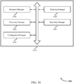
FIG. 10 shows a block diagram 1000 of a receivingUE communications manager 1015 that supports traffic-priority-based silencing techniques for interference mitigation in accordance with various aspects of the present disclosure. The receivingUE communications manager 1015 may be an example of aspects of a receivingUE communications manager 815, a receivingUE communications manager 915, or a receivingUE communications manager 1115 described with reference toFIGs. 8 ,9 , and11 . The receivingUE communications manager 1015 may includeresource manager 1020, silencingmanager 1025,discovery manager 1030,reporting manager 1035, andconfiguration manager 1040. Each of these modules may communicate, directly or indirectly, with one another (e.g., via one or more buses). -
Resource manager 1020 may be an example of theresource manager 925 described with reference toFIG. 9 . As such, theresource manager 1020 may be capable of performing the functions of theresource manager 925. - Silencing
manager 1025 may be an example of the silencingmanager 930 described with reference toFIG. 9 . As such, the silencingmanager 1025 may be capable of performing the functions of the silencingmanager 930. -
Discovery manager 1030 may receive a discovery message indicating that the second UE is capable of generating priority traffic. In some cases, the discovery message is a device-to-device communication received directly from the second UE.Reporting manager 1035 may transmit a reporting message to a base station indicating that the second UE has received the discovery message from the first UE. -
Configuration manager 1040 may receive, from a base station, a configuration message indicating a zone assigned to the first UE and that the semi-persistent resources are associated with the zone. In some cases, the zone is based on the second UE being capable of generating priority traffic. -
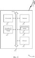
FIG. 11 shows a diagram of asystem 1100 including adevice 1105 that supports traffic-priority-based silencing techniques for interference mitigation in accordance with various aspects of the present disclosure.Device 1105 may be an example of or include the components ofwireless device 805,wireless device 905, or a receiving UE 115-c as described above, e.g., with reference toFIGs. 1-9 .Device 1105 may include components for bi-directional voice and data communications including components for transmitting and receiving communications, including receivingUE communications manager 1115,processor 1120,memory 1125,software 1130,transceiver 1135, and I/O controller 1140. These components may be in electronic communication via one or more busses (e.g., bus 1110). -
Processor 1120 may include an intelligent hardware device, (e.g., a general-purpose processor, a DSP, a central processing unit (CPU), a microcontroller, an ASIC, an FPGA, a programmable logic device, a discrete gate or transistor logic component, a discrete hardware component, or any combination thereof). In some cases,processor 1120 may be configured to operate a memory array using a memory controller. In other cases, a memory controller may be integrated intoprocessor 1120.Processor 1120 may be configured to execute computer-readable instructions stored in a memory to perform various functions (e.g., functions or tasks supporting traffic-priority-based silencing techniques for interference mitigation). -
Memory 1125 may include random access memory (RAM) and read only memory (ROM). Thememory 1125 may store computer-readable, computer-executable software 1130 including instructions that, when executed, cause the processor to perform various functions described herein. In some cases, thememory 1125 may contain, among other things, a basic input/output system (BIOS) which may control basic hardware and/or software operation such as the interaction with peripheral components or devices. -
Software 1130 may include code to implement aspects of the present disclosure, including code to support traffic-priority-based silencing techniques for interference mitigation.Software 1130 may be stored in a non-transitory computer-readable medium such as system memory or other memory. In some cases, thesoftware 1130 may not be directly executable by the processor but may cause a computer (e.g., when compiled and executed) to perform functions described herein. -
Transceiver 1135 may communicate bi-directionally, via one or more antennas, wired, or wireless links as described above. For example, thetransceiver 1135 may represent a wireless transceiver and may communicate bi-directionally with another wireless transceiver. Thetransceiver 1135 may also include a modem to modulate the packets and provide the modulated packets to the antennas for transmission, and to demodulate packets received from the antennas. - I/
O controller 1140 may manage input and output signals fordevice 1105. I/O controller 1140 may also manage peripherals not integrated intodevice 1105. In some cases, I/O controller 1140 may represent a physical connection or port to an external peripheral. In some cases, I/O controller 1140 may utilize an operating system such as iOS®, ANDROID®, MS-DOS®, MS-WINDOWS®, OS/2®, UNIX®, LINUX®, or another known operating system. -
FIG. 12 shows a block diagram 1200 of awireless device 1205 that supports traffic-priority-based silencing techniques for interference mitigation in accordance with various aspects of the present disclosure.Wireless device 1205 may be an example of aspects of a transmitting UE 115-a as described with reference toFIGs. 1-8 .Wireless device 1205 may includereceiver 1210, transmittingUE communications manager 1215, andtransmitter 1220.Wireless device 1205 may also include a processor. Each of these components may be in communication with one another (e.g., via one or more buses). -
Receiver 1210 may receive information such as packets, user data, or control information associated with various information channels (e.g., control channels, data channels, and information related to traffic-priority-based silencing techniques for interference mitigation, etc.). Information may be passed on to other components of the device. Thereceiver 1210 may be an example of aspects of thetransceiver 1535 described with reference toFIG. 15 . - Transmitting
UE communications manager 1215 may be an example of aspects of the transmittingUE communications manager 1515 described with reference toFIG. 15 . TransmittingUE communications manager 1215 and/or at least some of its various sub-components may be implemented in hardware, software executed by a processor, firmware, or any combination thereof. If implemented in software executed by a processor, the functions of the transmittingUE communications manager 1215 and/or at least some of its various sub-components may be executed by a general-purpose processor, a DSP, an ASIC, an FPGA or other programmable logic device, discrete gate or transistor logic, discrete hardware components, or any combination thereof designed to perform the functions described in the present disclosure. The transmittingUE communications manager 1215 and/or at least some of its various sub-components may be physically located at various positions, including being distributed such that portions of functions are implemented at different physical locations by one or more physical devices. In some examples, transmittingUE communications manager 1215 and/or at least some of its various sub-components may be a separate and distinct component in accordance with various aspects of the present disclosure. In other examples, transmittingUE communications manager 1215 and/or at least some of its various sub-components may be combined with one or more other hardware components, including but not limited to a receiver, a transmitter, a transceiver, one or more other components described in the present disclosure, or a combination thereof in accordance with various aspects of the present disclosure. - Transmitting
UE communications manager 1215 may identify, by a first UE, priority traffic to transmit to a base station, transmit, by the first UE, a silencing message to a second UE based on the identifying, the silencing message indicating to the second UE that the first UE is to communicate the priority traffic using semi-persistent resources, where the semi-persistent resources at least partially overlap with communication resources granted to the second UE, and transmit, by the first UE and to the base station, the priority traffic using the semi-persistent resources. -
Transmitter 1220 may transmit signals generated by other components of the device. In some examples, thetransmitter 1220 may be collocated with areceiver 1210 in a transceiver module. For example, thetransmitter 1220 may be an example of aspects of thetransceiver 1535 described with reference toFIG. 15 . Thetransmitter 1220 may include a single antenna, or it may include a set of antennas. -
FIG. 13 shows a block diagram 1300 of awireless device 1305 that supports traffic-priority-based silencing techniques for interference mitigation in accordance with various aspects of the present disclosure.Wireless device 1305 may be an example of aspects of awireless device 1205 or a transmitting UE 115-a as described with reference toFIGs. 1-8 and12 .Wireless device 1305 may includereceiver 1310, transmittingUE communications manager 1315, andtransmitter 1320.Wireless device 1305 may also include a processor. Each of these components may be in communication with one another (e.g., via one or more buses). -
Receiver 1310 may receive information such as packets, user data, or control information associated with various information channels (e.g., control channels, data channels, and information related to traffic-priority-based silencing techniques for interference mitigation, etc.). Information may be passed on to other components of the device. Thereceiver 1310 may be an example of aspects of thetransceiver 1535 described with reference toFIG. 15 . - Transmitting
UE communications manager 1315 may be an example of aspects of the transmittingUE communications manager 1515 described with reference toFIG. 15 . TransmittingUE communications manager 1315 may also includepriority traffic manager 1325 and silencingmanager 1330. -
Priority traffic manager 1325 may identify, by a first UE, priority traffic to transmit to a base station and transmit, by the first UE and to the base station, the priority traffic using the semi-persistent resources. In some cases, the priority traffic is transmitted during the first semi-persistent resources available after the silencing message is transmitted. - Silencing
manager 1330 may transmit, by the first UE, a silencing message to a second UE based on the identifying, the silencing message indicating to the second UE that the first UE is to communicate the priority traffic using semi-persistent resources, where the semi-persistent resources at least partially overlap with communication resources granted to the second UE. In some cases, the silencing message is a device-to-device communication transmitted directly to the second UE. -
Transmitter 1320 may transmit signals generated by other components of the device. In some examples, thetransmitter 1320 may be collocated with areceiver 1310 in a transceiver module. For example, thetransmitter 1320 may be an example of aspects of thetransceiver 1535 described with reference toFIG. 15 . Thetransmitter 1320 may include a single antenna, or it may include a set of antennas. -
FIG. 14 shows a block diagram 1400 of a transmittingUE communications manager 1415 that supports traffic-priority-based silencing techniques for interference mitigation in accordance with various aspects of the present disclosure. The transmittingUE communications manager 1415 may be an example of aspects of a transmittingUE communications manager 1515 described with reference toFIGs. 12 ,13 , and15 . The transmittingUE communications manager 1415 may includepriority traffic manager 1420, silencingmanager 1425,discovery manager 1430, andconfiguration manager 1435. Each of these modules may communicate, directly or indirectly, with one another (e.g., via one or more buses). -
Priority traffic manager 1420 may be an example of thepriority traffic manager 1325 described with reference toFIG. 13 . As such, thepriority traffic manager 1420 may be capable of performing the functions of thepriority traffic manager 1325. - Silencing
manager 1425 may be an example of the silencingmanager 1330 described with reference toFIG. 13 . As such, the silencingmanager 1425 may be capable of performing the functions of the silencingmanager 1330. -
Discovery manager 1430 may broadcast a discovery message to the second UE indicating that the first UE is capable of generating priority traffic. In some cases, the discovery message is a device-to-device communication transmitted directly to the second UE. -
Configuration manager 1435 may receive, from the base station, a configuration message indicating that the semi-persistent resources are reserved for use by the priority traffic. -
FIG. 15 shows a diagram of asystem 1500 including adevice 1505 that supports traffic-priority-based silencing techniques for interference mitigation in accordance with various aspects of the present disclosure.Device 1505 may be an example of or include the components of transmitting UE 115-a as described above, e.g., with reference toFIGs. 1-8 and12 .Device 1505 may include components for bi-directional voice and data communications including components for transmitting and receiving communications, including transmittingUE communications manager 1515,processor 1520,memory 1525,software 1530,transceiver 1535, and I/O controller 1540. These components may be in electronic communication via one or more busses (e.g., bus 1510). -
Processor 1520 may include an intelligent hardware device, (e.g., a general-purpose processor, a DSP, a CPU, a microcontroller, an ASIC, an FPGA, a programmable logic device, a discrete gate or transistor logic component, a discrete hardware component, or any combination thereof). In some cases,processor 1520 may be configured to operate a memory array using a memory controller. In other cases, a memory controller may be integrated intoprocessor 1520.Processor 1520 may be configured to execute computer-readable instructions stored in a memory to perform various functions (e.g., functions or tasks supporting traffic-priority-based silencing techniques for interference mitigation). -
Memory 1525 may include RAM and ROM. Thememory 1525 may store computer-readable, computer-executable software 1530 including instructions that, when executed, cause the processor to perform various functions described herein. In some cases, thememory 1525 may contain, among other things, a BIOS which may control basic hardware and/or software operation such as the interaction with peripheral components or devices. -
Software 1530 may include code to implement aspects of the present disclosure, including code to support traffic-priority-based silencing techniques for interference mitigation.Software 1530 may be stored in a non-transitory computer-readable medium such as system memory or other memory. In some cases, thesoftware 1530 may not be directly executable by the processor but may cause a computer (e.g., when compiled and executed) to perform functions described herein. -
Transceiver 1535 may communicate bi-directionally, via one or more antennas, wired, or wireless links as described above. For example, thetransceiver 1535 may represent a wireless transceiver and may communicate bi-directionally with another wireless transceiver. Thetransceiver 1535 may also include a modem to modulate the packets and provide the modulated packets to the antennas for transmission, and to demodulate packets received from the antennas. - I/
O controller 1540 may manage input and output signals fordevice 1505. I/O controller 1540 may also manage peripherals not integrated intodevice 1505. In some cases, I/O controller 1540 may represent a physical connection or port to an external peripheral. In some cases, I/O controller 1540 may utilize an operating system such as iOS®, ANDROID®, MS-DOS®, MS-WINDOWS®, OS/2®, UNIX®, LINUX®, or another known operating system. -
FIG. 16 shows a block diagram 1600 of awireless device 1605 that supports traffic-priority-based silencing techniques for interference mitigation in accordance with various aspects of the present disclosure.Wireless device 1605 may be an example of aspects of abase station 105 as described with reference toFIGs. 1-8 .Wireless device 1605 may includereceiver 1610, basestation communications manager 1615, andtransmitter 1620.Wireless device 1605 may also include a processor. Each of these components may be in communication with one another (e.g., via one or more buses). -
Receiver 1610 may receive information such as packets, user data, or control information associated with various information channels (e.g., control channels, data channels, and information related to traffic-priority-based silencing techniques for interference mitigation, etc.). Information may be passed on to other components of the device. Thereceiver 1610 may be an example of aspects of thetransceiver 1935 described with reference toFIG. 19 . - Base
station communications manager 1615 may be an example of aspects of the basestation communications manager 1915 described with reference toFIG. 19 . Basestation communications manager 1615 and/or at least some of its various sub-components may be implemented in hardware, software executed by a processor, firmware, or any combination thereof. If implemented in software executed by a processor, the functions of the basestation communications manager 1615 and/or at least some of its various sub-components may be executed by a general-purpose processor, a DSP, an ASIC, an FPGA or other programmable logic device, discrete gate or transistor logic, discrete hardware components, or any combination thereof designed to perform the functions described in the present disclosure. The basestation communications manager 1615 and/or at least some of its various sub-components may be physically located at various positions, including being distributed such that portions of functions are implemented at different physical locations by one or more physical devices. In some examples, basestation communications manager 1615 and/or at least some of its various sub-components may be a separate and distinct component in accordance with various aspects of the present disclosure. In other examples, basestation communications manager 1615 and/or at least some of its various sub-components may be combined with one or more other hardware components, including but not limited to a receiver, a transmitter, a transceiver, one or more other components described in the present disclosure, or a combination thereof in accordance with various aspects of the present disclosure. - Base
station communications manager 1615 may receive, by a base station, a reporting message from a first UE indicating that the first UE is capable of receiving messages transmitted by a second UE and that the second UE is capable of generating priority traffic, assign semi-persistent resources to be used by the second UE to transmit the priority traffic, and transmit a configuration message to the second UE indicating the assigned semi-persistent resources. -
Transmitter 1620 may transmit signals generated by other components of the device. In some examples, thetransmitter 1620 may be collocated with areceiver 1610 in a transceiver module. For example, thetransmitter 1620 may be an example of aspects of thetransceiver 1935 described with reference toFIG. 19 . Thetransmitter 1620 may include a single antenna, or it may include a set of antennas. -
FIG. 17 shows a block diagram 1700 of awireless device 1705 that supports traffic-priority-based silencing techniques for interference mitigation in accordance with various aspects of the present disclosure.Wireless device 1705 may be an example of aspects of awireless device 1605 or abase station 105 as described with reference toFIGs. 1-8 and 16.Wireless device 1705 may includereceiver 1710, basestation communications manager 1715, andtransmitter 1720.Wireless device 1705 may also include a processor. Each of these components may be in communication with one another (e.g., via one or more buses). -
Receiver 1710 may receive information such as packets, user data, or control information associated with various information channels (e.g., control channels, data channels, and information related to traffic-priority-based silencing techniques for interference mitigation, etc.). Information may be passed on to other components of the device. Thereceiver 1710 may be an example of aspects of thetransceiver 1935 described with reference toFIG. 19 . - Base
station communications manager 1715 may be an example of aspects of the basestation communications manager 1915 described with reference toFIG. 19 . Basestation communications manager 1715 may also includereporting manager 1725,resource manager 1730, andconfiguration manager 1735. -
Reporting manager 1725 may receive, by a base station, a reporting message from a first UE indicating that the first UE is capable of receiving messages transmitted by a second UE and that the second UE is capable of generating priority traffic. Theresporting manager 1725 may receive a second reporting message indicating that a third UE different from the second UE is capable of generating priority traffic, where the zone and the semi-persistent resources are based on the reporting message and the second reporting message. -
Resource manager 1730 may assign semi-persistent resources to be used by the second UE to transmit the priority traffic. Theresource manager 1730 may grant an assignment of communication resources to traffic generated by the first UE, the communication resources at least partially overlapping with the semi-persistent resources, where the traffic has a lower priority than the priority traffic. Theresource manager 1730 may transmit a scheduling message to the first UE rescheduling the traffic based on the determining. -
Configuration manager 1735 may transmit a configuration message to the second UE indicating the assigned semi-persistent resources. -
Transmitter 1720 may transmit signals generated by other components of the device. In some examples, thetransmitter 1720 may be collocated with areceiver 1710 in a transceiver module. For example, thetransmitter 1720 may be an example of aspects of thetransceiver 1935 described with reference toFIG. 19 . Thetransmitter 1720 may include a single antenna, or it may include a set of antennas. -
FIG. 18 shows a block diagram 1800 of a basestation communications manager 1815 that supports traffic-priority-based silencing techniques for interference mitigation in accordance with various aspects of the present disclosure. The basestation communications manager 1815 may be an example of aspects of a basestation communications manager 1915 described with reference toFIGs. 16 ,17 , and19 . The basestation communications manager 1815 may includereporting manager 1820,resource manager 1825,configuration manager 1830,zone manager 1835, andpriority traffic manager 1840. Each of these modules may communicate, directly or indirectly, with one another (e.g., via one or more buses). -
Reporting manager 1820 may be an example of thereporting manager 1725 described with reference toFIG. 17 . As such, thereporting manager 1820 may be capable of performing the functions of thereporting manager 1725. -
Resource manager 1825 may be an example of theresource manager 1730 described with reference toFIG. 17 . As such, theresource manager 1825 may be capable of performing the functions of theresource manager 1730. -
Configuration manager 1830 may transmit a configuration message to the second UE indicating the assigned semi-persistent resources. -
Zone manager 1835 may generate a zone based on receiving the reporting message, the semi-persistent resources being associated with the zone, where the configuration message indicates the zone. -
Priority traffic manager 1840 may receive, from the second UE, the priority traffic using at least a portion of the communication resources granted to the traffic and determine that traffic scheduled to be received using communication resources that at least partially overlap with the semi-persistent resources was not received. -
FIG. 19 shows a diagram of asystem 1900 including adevice 1905 that supports traffic-priority-based silencing techniques for interference mitigation in accordance with various aspects of the present disclosure.Device 1905 may be an example of or include the components ofbase station 105 as described above, e.g., with reference toFIGs. 1-8 and16 .Device 1905 may include components for bi-directional voice and data communications including components for transmitting and receiving communications, including basestation communications manager 1915,processor 1920,memory 1925,software 1930,transceiver 1935,antenna 1940, andnetwork communications manager 1945. These components may be in electronic communication via one or more busses (e.g., bus 1910).Device 1905 may communicate wirelessly with one ormore UEs 115. - Base
station communications manager 1915 may manage communications withother base station 105, and may include a controller or scheduler for controlling communications withUEs 115 in cooperation withother base stations 105. For example, the basestation communications manager 1915 may coordinate scheduling for transmissions to UEs 115 for various interference mitigation techniques such as beamforming or joint transmission. In some examples, basestation communications manager 1915 may provide an X2 interface within LTE/LTE-A wireless communication network technology to provide communication betweenbase stations 105. - In some examples, base
station communications manager 1915 may manage communications withother base station 105, and may include a controller or scheduler for controlling communications withUEs 115 in cooperation withother base stations 105. For example, the basestation communications manager 1915 may coordinate scheduling for transmissions to UEs 115 for various interference mitigation techniques such as beamforming or joint transmission. In some examples, basestation communications manager 1915 may provide an X2 interface within an LTE/LTE-A wireless communication network technology to provide communication betweenbase stations 105. -
Processor 1920 may include an intelligent hardware device, (e.g., a general-purpose processor, a DSP, a CPU, a microcontroller, an ASIC, an FPGA, a programmable logic device, a discrete gate or transistor logic component, a discrete hardware component, or any combination thereof). In some cases,processor 1920 may be configured to operate a memory array using a memory controller. In other cases, a memory controller may be integrated intoprocessor 1920.Processor 1920 may be configured to execute computer-readable instructions stored in a memory to perform various functions (e.g., functions or tasks supporting traffic-priority-based silencing techniques for interference mitigation). -
Memory 1925 may include RAM and ROM. Thememory 1925 may store computer-readable, computer-executable software 1930 including instructions that, when executed, cause the processor to perform various functions described herein. In some cases, thememory 1925 may contain, among other things, a BIOS which may control basic hardware and/or software operation such as the interaction with peripheral components or devices. -
Software 1930 may include code to implement aspects of the present disclosure, including code to support traffic-priority-based silencing techniques for interference mitigation.Software 1930 may be stored in a non-transitory computer-readable medium such as system memory or other memory. In some cases, thesoftware 1930 may not be directly executable by the processor but may cause a computer (e.g., when compiled and executed) to perform functions described herein. -
Transceiver 1935 may communicate bi-directionally, via one or more antennas, wired, or wireless links as described above. For example, thetransceiver 1935 may represent a wireless transceiver and may communicate bi-directionally with another wireless transceiver. Thetransceiver 1935 may also include a modem to modulate the packets and provide the modulated packets to the antennas for transmission, and to demodulate packets received from the antennas. - In some cases, the wireless device may include a
single antenna 1940. However, in some cases the device may have more than oneantenna 1940, which may be capable of concurrently transmitting or receiving multiple wireless transmissions. -
Network communications manager 1945 may manage communications with the core network (e.g., via one or more wired backhaul links). For example, thenetwork communications manager 1945 may manage the transfer of data communications for client devices, such as one ormore UEs 115. -
FIG. 20 shows a flowchart illustrating amethod 2000 for traffic-priority-based silencing techniques for interference mitigation in accordance with various aspects of the present disclosure. The operations ofmethod 2000 may be implemented by a receiving UE 115-c or its components as described herein. For example, the operations ofmethod 2000 may be performed by a receiving UE communications manager as described with reference toFIGs. 8 through 11 . In some examples, a receiving UE 115-c may execute a set of codes to control the functional elements of the device to perform the functions described below. Additionally or alternatively, the receiving UE 115-c may perform aspects of the functions described below using special-purpose hardware. - At
block 2005 the receiving UE 115-c may receive, by a first UE, a grant of communication resources. The operations ofblock 2005 may be performed according to the methods described with reference toFIGs. 1 through 7 . In certain examples, aspects of the operations ofblock 2005 may be performed by a resource manager as described with reference toFIGs. 8 through 11 . - At block 2010 the receiving UE 115-c may receive a silencing message from a second UE, the silencing message indicating that the second UE is to communicate priority traffic using semi-persistent resources, wherein the semi-persistent resources at least partially overlap with the communication resources. The operations of block 2010 may be performed according to the methods described with reference to
FIGs. 1 through 7 . In certain examples, aspects of the operations of block 2010 may be performed by a silencing manager as described with reference toFIGs. 8 through 11 . - At block 2015 the receiving UE 115-c may release at least a portion of the communication resources based at least in part on the silencing message. The operations of block 2015 may be performed according to the methods described with reference to
FIGs. 1 through 7 . In certain examples, aspects of the operations of block 2015 may be performed by a silencing manager as described with reference toFIGs. 8 through 11 . -
FIG. 21 shows a flowchart illustrating amethod 2100 for traffic-priority-based silencing techniques for interference mitigation in accordance with various aspects of the present disclosure. The operations ofmethod 2100 may be implemented by a receiving UE 115-c or its components as described herein. For example, the operations ofmethod 2100 may be performed by a receiving UE communications manager as described with reference toFIGs. 8 through 11 . In some examples, a receiving UE 115-c may execute a set of codes to control the functional elements of the device to perform the functions described below. Additionally or alternatively, the receiving UE 115-c may perform aspects of the functions described below using special-purpose hardware. - At
block 2105 the receiving UE 115-c may receive a discovery message indicating that the second UE is capable of generating priority traffic. The operations ofblock 2105 may be performed according to the methods described with reference toFIGs. 1 through 7 . In certain examples, aspects of the operations ofblock 2105 may be performed by a discovery manager as described with reference toFIGs. 8 through 11 . - At block 2110 the receiving UE 115-c may transmit a reporting message to a base station indicating that the second UE has received the discovery message from the first UE. The operations of block 2110 may be performed according to the methods described with reference to
FIGs. 1 through 7 . In certain examples, aspects of the operations of block 2110 may be performed by a reporting manager as described with reference toFIGs. 8 through 11 . - At
block 2115 the receiving UE 115-c may receive, by a first UE, a grant of communication resources. The operations ofblock 2115 may be performed according to the methods described with reference toFIGs. 1 through 7 . In certain examples, aspects of the operations ofblock 2115 may be performed by a resource manager as described with reference toFIGs. 8 through 11 . - At block 2120 the receiving UE 115-c may receive a silencing message from a second UE, the silencing message indicating that the second UE is to communicate priority traffic using semi-persistent resources, wherein the semi-persistent resources at least partially overlap with the communication resources. The operations of block 2120 may be performed according to the methods described with reference to
FIGs. 1 through 7 . In certain examples, aspects of the operations of block 2120 may be performed by a silencing manager as described with reference toFIGs. 8 through 11 . - At
block 2125 the receiving UE 115-c may release at least a portion of the communication resources based at least in part on the silencing message. The operations ofblock 2125 may be performed according to the methods described with reference toFIGs. 1 through 7 . In certain examples, aspects of the operations ofblock 2125 may be performed by a silencing manager as described with reference toFIGs. 8 through 11 . -
FIG. 22 shows a flowchart illustrating amethod 2200 for traffic-priority-based silencing techniques for interference mitigation in accordance with various aspects of the present disclosure. The operations ofmethod 2200 may be implemented by a transmitting UE 115-a or its components as described herein. For example, the operations ofmethod 2200 may be performed by a transmitting UE communications manager as described with reference toFIGs. 12 through 15 . In some examples, a transmitting UE 115-a may execute a set of codes to control the functional elements of the device to perform the functions described below. Additionally or alternatively, the transmitting UE 115-a may perform aspects of the functions described below using special-purpose hardware. - At
block 2205 the transmitting UE 115-a may identify, by a first UE, priority traffic to transmit to a base station. The operations ofblock 2205 may be performed according to the methods described with reference toFIGs. 1 through 7 . In certain examples, aspects of the operations ofblock 2205 may be performed by a priority traffic manager as described with reference toFIGs. 12 through 15 . - At
block 2210 the transmitting UE 115-a may transmit, by the first UE, a silencing message to a second UE based at least in part on the identifying, the silencing message indicating to the second UE that the first UE is to communicate the priority traffic using semi-persistent resources, wherein the semi-persistent resources at least partially overlap with communication resources granted to the second UE. The operations ofblock 2210 may be performed according to the methods described with reference toFIGs. 1 through 7 . In certain examples, aspects of the operations ofblock 2210 may be performed by a silencing manager as described with reference toFIGs. 12 through 15 . - At block 2215 the transmitting UE 115-a may transmit, by the first UE and to the base station, the priority traffic using the semi-persistent resources. The operations of block 2215 may be performed according to the methods described with reference to
FIGs. 1 through 7 . In certain examples, aspects of the operations of block 2215 may be performed by a priority traffic manager as described with reference toFIGs. 12 through 15 . -
FIG. 23 shows a flowchart illustrating amethod 2300 for traffic-priority-based silencing techniques for interference mitigation in accordance with various aspects of the present disclosure. The operations ofmethod 2300 may be implemented by a transmitting UE 115-a or its components as described herein. For example, the operations ofmethod 2300 may be performed by a transmitting UE communications manager as described with reference toFIGs. 12 through 15 . In some examples, a transmitting UE 115-a may execute a set of codes to control the functional elements of the device to perform the functions described below. Additionally or alternatively, the transmitting UE 115-a may perform aspects of the functions described below using special-purpose hardware. - At block 2305 the transmitting UE 115-a may broadcast a discovery message to the second UE indicating that the first UE is capable of generating priority traffic. The operations of block 2305 may be performed according to the methods described with reference to
FIGs. 1 through 7 . In certain examples, aspects of the operations of block 2305 may be performed by a discovery manager as described with reference toFIGs. 12 through 15 . - At block 2310 the transmitting UE 115-a may receive, from the base station, a configuration message indicating that the semi-persistent resources are reserved for use by the priority traffic. The operations of block 2310 may be performed according to the methods described with reference to
FIGs. 1 through 7 . In certain examples, aspects of the operations of block 2310 may be performed by a configuration manager as described with reference toFIGs. 12 through 15 . - At
block 2315 the transmitting UE 115-a may identify, by a first UE, priority traffic to transmit to a base station. The operations ofblock 2315 may be performed according to the methods described with reference toFIGs. 1 through 7 . In certain examples, aspects of the operations ofblock 2315 may be performed by a priority traffic manager as described with reference toFIGs. 12 through 15 . - At block 2320 the transmitting UE 115-a may transmit, by the first UE, a silencing message to a second UE based at least in part on the identifying, the silencing message indicating to the second UE that the first UE is to communicate the priority traffic using semi-persistent resources, wherein the semi-persistent resources at least partially overlap with communication resources granted to the second UE. The operations of block 2320 may be performed according to the methods described with reference to
FIGs. 1 through 7 . In certain examples, aspects of the operations of block 2320 may be performed by a silencing manager as described with reference toFIGs. 12 through 15 . - At
block 2325 the transmitting UE 115-a may transmit, by the first UE and to the base station, the priority traffic using the semi-persistent resources. The operations ofblock 2325 may be performed according to the methods described with reference toFIGs. 1 through 7 . In certain examples, aspects of the operations ofblock 2325 may be performed by a priority traffic manager as described with reference toFIGs. 12 through 15 . -
FIG. 24 shows a flowchart illustrating amethod 2400 for traffic-priority-based silencing techniques for interference mitigation in accordance with various aspects of the present disclosure. The operations ofmethod 2400 may be implemented by abase station 105 or its components as described herein. For example, the operations ofmethod 2400 may be performed by a base station communications manager as described with reference toFIGs. 16 through 19 . In some examples, abase station 105 may execute a set of codes to control the functional elements of the device to perform the functions described below. Additionally or alternatively, thebase station 105 may perform aspects of the functions described below using special-purpose hardware. - At
block 2405 thebase station 105 may receive, by a base station, a reporting message from a first UE indicating that the first UE is capable of receiving messages transmitted by a second UE and that the second UE is capable of generating priority traffic. The operations ofblock 2405 may be performed according to the methods described with reference toFIGs. 1 through 7 . In certain examples, aspects of the operations ofblock 2405 may be performed by a reporting manager as described with reference toFIGs. 16 through 19 . - At
block 2410 thebase station 105 may assign semi-persistent resources to be used by the second UE to transmit the priority traffic. The operations ofblock 2410 may be performed according to the methods described with reference toFIGs. 1 through 7 . In certain examples, aspects of the operations ofblock 2410 may be performed by a resource manager as described with reference toFIGs. 16 through 19 . - At block 2415 the
base station 105 may transmit a configuration message to the second UE indicating the assigned semi-persistent resources. The operations of block 2415 may be performed according to the methods described with reference toFIGs. 1 through 7 . In certain examples, aspects of the operations of block 2415 may be performed by a configuration manager as described with reference toFIGs. 16 through 19 . -
FIG. 25 shows a flowchart illustrating amethod 2500 for traffic-priority-based silencing techniques for interference mitigation in accordance with various aspects of the present disclosure. The operations ofmethod 2500 may be implemented by abase station 105 or its components as described herein. For example, the operations ofmethod 2500 may be performed by a base station communications manager as described with reference toFIGs. 16 through 19 . In some examples, abase station 105 may execute a set of codes to control the functional elements of the device to perform the functions described below. Additionally or alternatively, thebase station 105 may perform aspects of the functions described below using special-purpose hardware. - At
block 2505 thebase station 105 may receive, by a base station, a reporting message from a first UE indicating that the first UE is capable of receiving messages transmitted by a second UE and that the second UE is capable of generating priority traffic. The operations ofblock 2505 may be performed according to the methods described with reference toFIGs. 1 through 7 . In certain examples, aspects of the operations ofblock 2505 may be performed by a reporting manager as described with reference toFIGs. 16 through 19 . - At block 2510 the
base station 105 may assign semi-persistent resources to be used by the second UE to transmit the priority traffic. The operations of block 2510 may be performed according to the methods described with reference toFIGs. 1 through 7 . In certain examples, aspects of the operations of block 2510 may be performed by a resource manager as described with reference toFIGs. 16 through 19 . - At block 2515 the
base station 105 may transmit a configuration message to the second UE indicating the assigned semi-persistent resources. The operations of block 2515 may be performed according to the methods described with reference toFIGs. 1 through 7 . In certain examples, aspects of the operations of block 2515 may be performed by a configuration manager as described with reference toFIGs. 16 through 19 . - At
block 2520 thebase station 105 may grant an assignment of communication resources to traffic generated by the first UE, the communication resources at least partially overlapping with the semi-persistent resources, wherein the traffic has a lower priority than the priority traffic. The operations ofblock 2520 may be performed according to the methods described with reference toFIGs. 1 through 7 . In certain examples, aspects of the operations ofblock 2520 may be performed by a resource manager as described with reference toFIGs. 16 through 19 . - At block 2525 the
base station 105 may receive, from the second UE, the priority traffic using at least a portion of the communication resources granted to the traffic. The operations of block 2525 may be performed according to the methods described with reference toFIGs. 1 through 7 . In certain examples, aspects of the operations of block 2525 may be performed by a priority traffic manager as described with reference toFIGs. 16 through 19 . - It should be noted that the methods described above describe possible implementations, and that the operations and the steps may be rearranged or otherwise modified and that other implementations are possible. Furthermore, aspects from two or more of the methods may be combined.
- Techniques described herein may be used for various wireless communications systems such as code division multiple access (CDMA), time division multiple access (TDMA), frequency division multiple access (FDMA), orthogonal frequency division multiple access (OFDMA), single carrier frequency division multiple access (SC-FDMA), and other systems. The terms "system" and "network" are often used interchangeably. A code division multiple access (CDMA) system may implement a radio technology such as CDMA2000, Universal Terrestrial Radio Access (UTRA), etc. CDMA2000 covers IS-2000, IS-95, and IS-856 standards. IS-2000 Releases may be commonly referred to as CDMA2000 IX, IX, etc. IS-856 (TIA-856) is commonly referred to as CDMA2000 1xEV-DO, High Rate Packet Data (HRPD), etc. UTRA includes Wideband CDMA (WCDMA) and other variants of CDMA. A time division multiple access (TDMA) system may implement a radio technology such as Global System for Mobile Communications (GSM).
- An orthogonal frequency division multiple access (OFDMA) system may implement a radio technology such as Ultra Mobile Broadband (UMB), Evolved UTRA (E-UTRA), Institute of Electrical and Electronics Engineers (IEEE) 802.11 (Wi-Fi), IEEE 802.16 (WiMAX), IEEE 802.20, Flash-OFDM, etc. UTRA and E-UTRA are part of Universal Mobile Telecommunications system (UMTS). 3GPP LTE and LTE-Advanced (LTE-A) are releases of Universal Mobile Telecommunications System (UMTS) that use E-UTRA. UTRA, E-UTRA, UMTS, LTE, LTE-A, NR, and Global System for Mobile communications (GSM) are described in documents from the organization named "3rd Generation Partnership Project" (3GPP). CDMA2000 and UMB are described in documents from an organization named "3rd Generation Partnership Project 2" (3GPP2). The techniques described herein may be used for the systems and radio technologies mentioned above as well as other systems and radio technologies. While aspects an LTE or an NR system may be described for purposes of example, and LTE or NR terminology may be used in much of the description, the techniques described herein are applicable beyond LTE or NR applications.
- In LTE/LTE-A networks, including such networks described herein, the term evolved node B (eNB) may be generally used to describe the base stations. The wireless communications system or systems described herein may include a heterogeneous LTE/LTE-A or NR network in which different types of evolved node B (eNBs) provide coverage for various geographical regions. For example, each eNB, gNB or base station may provide communication coverage for a macro cell, a small cell, or other types of cell. The term "cell" may be used to describe a base station, a carrier or component carrier associated with a base station, or a coverage area (e.g., sector, etc.) of a carrier or base station, depending on context.
- Base stations may include or may be referred to by those skilled in the art as a base transceiver station, a radio base station, an access point, a radio transceiver, a NodeB, eNodeB (eNB), next generation NodeB (gNB), Home NodeB, a Home eNodeB, or some other suitable terminology. The geographic coverage area for a base station may be divided into sectors making up only a portion of the coverage area. The wireless communications system or systems described herein may include base stations of different types (e.g., macro or small cell base stations). The UEs described herein may be able to communicate with various types of base stations and network equipment including macro eNBs, small cell eNBs, gNBs, relay base stations, and the like. There may be overlapping geographic coverage areas for different technologies.
- A macro cell generally covers a relatively large geographic area (e.g., several kilometers in radius) and may allow unrestricted access by UEs with service subscriptions with the network provider. A small cell is a lower-powered base station, as compared with a macro cell, that may operate in the same or different (e.g., licensed, unlicensed, etc.) frequency bands as macro cells. Small cells may include pico cells, femto cells, and micro cells according to various examples. A pico cell, for example, may cover a small geographic area and may allow unrestricted access by UEs with service subscriptions with the network provider. A femto cell may also cover a small geographic area (e.g., a home) and may provide restricted access by UEs having an association with the femto cell (e.g., UEs in a closed subscriber group (CSG), UEs for users in the home, and the like). An eNB for a macro cell may be referred to as a macro eNB. An eNB for a small cell may be referred to as a small cell eNB, a pico eNB, a femto eNB, or a home eNB. An eNB may support one or multiple (e.g., two, three, four, and the like) cells (e.g., component carriers).
- The wireless communications system or systems described herein may support synchronous or asynchronous operation. For synchronous operation, the base stations may have similar frame timing, and transmissions from different base stations may be approximately aligned in time. For asynchronous operation, the base stations may have different frame timing, and transmissions from different base stations may not be aligned in time. The techniques described herein may be used for either synchronous or asynchronous operations.
- The downlink transmissions described herein may also be called forward link transmissions while the uplink transmissions may also be called reverse link transmissions. Each communication link described herein-including, for example,
wireless communication systems FIGs. 1 and2 -may include one or more carriers, where each carrier may be a signal made up of multiple sub-carriers (e.g., waveform signals of different frequencies). - The description set forth herein, in connection with the appended drawings, describes example configurations and does not represent all the examples that may be implemented or that are within the scope of the claims. The term "exemplary" used herein means "serving as an example, instance, or illustration," and not "preferred" or "advantageous over other examples." The detailed description includes specific details for the purpose of providing an understanding of the described techniques. These techniques, however, may be practiced without these specific details. In some instances, well-known structures and devices are shown in block diagram form in order to avoid obscuring the concepts of the described examples.
- In the appended figures, similar components or features may have the same reference label. Further, various components of the same type may be distinguished by following the reference label by a dash and a second label that distinguishes among the similar components. If just the first reference label is used in the specification, the description is applicable to any one of the similar components having the same first reference label irrespective of the second reference label.
- Information and signals described herein may be represented using any of a variety of different technologies and techniques. For example, data, instructions, commands, information, signals, bits, symbols, and chips that may be referenced throughout the above description may be represented by voltages, currents, electromagnetic waves, magnetic fields or particles, optical fields or particles, or any combination thereof.
- The various illustrative blocks and modules described in connection with the disclosure herein may be implemented or performed with a general-purpose processor, a DSP, an ASIC, an FPGA or other programmable logic device, discrete gate or transistor logic, discrete hardware components, or any combination thereof designed to perform the functions described herein. A general-purpose processor may be a microprocessor, but in the alternative, the processor may be any conventional processor, controller, microcontroller, or state machine. A processor may also be implemented as a combination of computing devices (e.g., a combination of a DSP and a microprocessor, multiple microprocessors, one or more microprocessors in conjunction with a DSP core, or any other such configuration).
- The functions described herein may be implemented in hardware, software executed by a processor, firmware, or any combination thereof. If implemented in software executed by a processor, the functions may be stored on or transmitted over as one or more instructions or code on a computer-readable medium. Other examples and implementations are within the scope of the disclosure and appended claims. For example, due to the nature of software, functions described above can be implemented using software executed by a processor, hardware, firmware, hardwiring, or combinations of any of these. Features implementing functions may also be physically located at various positions, including being distributed such that portions of functions are implemented at different physical locations. Also, as used herein, including in the claims, "or" as used in a list of items (for example, a list of items prefaced by a phrase such as "at least one of' or "one or more of') indicates an inclusive list such that, for example, a list of at least one of A, B, or C means A or B or C or AB or AC or BC or ABC (i.e., A and B and C). Also, as used herein, the phrase "based on" shall not be construed as a reference to a closed set of conditions. For example, an exemplary step that is described as "based on condition A" may be based on both a condition A and a condition B without departing from the scope of the present disclosure. In other words, as used herein, the phrase "based on" shall be construed in the same manner as the phrase "based at least in part on."
- Computer-readable media includes both non-transitory computer storage media and communication media including any medium that facilitates transfer of a computer program from one place to another. A non-transitory storage medium may be any available medium that can be accessed by a general purpose or special purpose computer. By way of example, and not limitation, non-transitory computer-readable media may comprise RAM, ROM, electrically erasable programmable read only memory (EEPROM), compact disk (CD) ROM or other optical disk storage, magnetic disk storage or other magnetic storage devices, or any other non-transitory medium that can be used to carry or store desired program code means in the form of instructions or data structures and that can be accessed by a general-purpose or special-purpose computer, or a general-purpose or special-purpose processor. Also, any connection is properly termed a computer-readable medium. For example, if the software is transmitted from a website, server, or other remote source using a coaxial cable, fiber optic cable, twisted pair, digital subscriber line (DSL), or wireless technologies such as infrared, radio, and microwave, then the coaxial cable, fiber optic cable, twisted pair, digital subscriber line (DSL), or wireless technologies such as infrared, radio, and microwave are included in the definition of medium. Disk and disc, as used herein, include CD, laser disc, optical disc, digital versatile disc (DVD), floppy disk and Blu-ray disc where disks usually reproduce data magnetically, while discs reproduce data optically with lasers. Combinations of the above are also included within the scope of computer-readable media.
- The description herein is provided to enable a person skilled in the art to make or use the disclosure. Various modifications to the disclosure will be readily apparent to those skilled in the art, and other variations may be applied without departing from the scope of the claims.
Claims (13)
- A method for wireless communication at a first user equipment "UE", comprising:receiving (2005), by the first UE, a grant of communication resources;receiving (2010) a silencing message from a second UE, the silencing message indicating that the second UE is to communicate priority traffic using semi-persistent resources, wherein the semi-persistent resources at least partially overlap with the communication resources;determining a next occurrence of the semi-persistent resources after receiving the silencing message; andreleasing at least a portion of the communication resources that at least partially overlap with the next occurrence of the semi-persistent resources based at least in part on the silencing message.
- The method of claim 1, wherein:
the silencing message is received during the same transmission time interval that the portion of the communication resources are released. - The method of claim 1, further comprising:receiving (2105) a discovery message indicating that the second UE is capable of generating priority traffic; andtransmitting (2110) a reporting message to a base station indicating that the first UE has received the discovery message from the second UE.
- The method of claim 3, wherein:
the discovery message is a device-to-device communication received directly from the second UE. - The method of claim 1, further comprising:refraining, by the first UE, from transmitting traffic during the communication resources based at least in part on releasing the communication resources, andreceiving, by the first UE, a second grant that includes new communication resources rescheduling the traffic for transmission, wherein the new communication resources are different from the communication resources.
- A method for wireless communication at a second user equipment "UE", comprising:identifying (2205), by the second UE, priority traffic to transmit to a base station;transmitting (2210), by the second UE, a silencing message to a first UE based at least in part on the identifying, the silencing message indicating to the first UE that the second UE is to communicate the priority traffic using semi-persistent resources and requesting that the first UE releases at least a portion of the granted communication resources that at least partially overlap with a next occurrence of the semi-persistent resources; andtransmitting, by the second UE and to the base station, the priority traffic using the semi-persistent resources, wherein the priority traffic is transmitted during the first semi-persistent resources available after the silencing message is transmitted.
- The method of claim 6, further comprising:broadcasting (2305) a discovery message to the first UE indicating that the second UE is capable of generating priority traffic, andthe discovery message is a device-to-device communication transmitted directly to the first UE.
- An apparatus (905, 1015) comprising a first user equipment "UE" for wireless communication in a system including the first UE and a second UE, the apparatus comprising:means (925, 1020) for receiving, by the first UE, a grant of communication resources;means (930, 1025) for receiving a silencing message from the second UE, the silencing message indicating that the second UE is to communicate priority traffic using semi-persistent resources, wherein the semi-persistent resources at least partially overlap with the communication resources;means (925, 1020) for determining a next occurrence of the semi-persistent resources after receiving the silencing message; andmeans (925, 1020) for releasing at least a portion of the communication resources that at least partially overlap with the next occurrence of the semi-persistent resources based at least in part on the silencing message.
- The apparatus of claim 8, wherein:
the silencing message is received during the same transmission time interval that the portion of the communication resources are released. - The apparatus of claim 8, further comprising:means (1030) for receiving a discovery message indicating that the second UE is capable of generating priority traffic; andmeans (1035) for transmitting a reporting message to a base station indicating that the first UE has received the discovery message from the second UE.
- The apparatus of claim 8, further comprising:means (930, 1025) for refraining, by the first UE, from transmitting traffic during the communication resources based at least in part on releasing the communication resources, andmeans (925, 1020) for receiving, by the first UE, a second grant that includes new communication resources rescheduling the traffic for transmission, wherein the new communication resources are different from the communication resources.
- An apparatus (1305, 1415) comprising a second user equipment "UE" for wireless communication in a system including a first UE and the second UE, the apparatus comprising:means (1325, 1420) for identifying, by the second UE, priority traffic to transmit to a base station;means (1330, 1425) for transmitting, by the second UE, a silencing message to the first UE based at least in part on the identifying, the silencing message indicating to the first UE that the second UE is to communicate the priority traffic using semi-persistent resources and requesting that the first UE releases at least a portion of the granted communication resources that at least partially overlap with a next occurrence of the semi-persistent resources; andmeans (1325, 1420) for transmitting, by the second UE and to the base station, the priority traffic using the semi-persistent resources, wherein the priority traffic is transmitted during the first semi-persistent resources available after the silencing message is transmitted.
- The apparatus of claim 12, further comprising:means (1430) for broadcasting a discovery message to the first UE indicating that the second UE is capable of generating priority traffic, andthe discovery message is a device-to-device communication transmitted directly to the first UE.
Applications Claiming Priority (2)
| Application Number | Priority Date | Filing Date | Title |
|---|---|---|---|
| US15/386,653 US10264595B2 (en) | 2016-12-21 | 2016-12-21 | Traffic-priority based silencing techniques for interference mitigation |
| PCT/US2017/063290 WO2018118340A1 (en) | 2016-12-21 | 2017-11-27 | Traffic-priority based silencing techniques for interference mitigation |
Publications (2)
| Publication Number | Publication Date |
|---|---|
| EP3560263A1 EP3560263A1 (en) | 2019-10-30 |
| EP3560263B1 true EP3560263B1 (en) | 2021-08-18 |
Family
ID=60543730
Family Applications (1)
| Application Number | Title | Priority Date | Filing Date |
|---|---|---|---|
| EP17808295.4A Active EP3560263B1 (en) | 2016-12-21 | 2017-11-27 | Traffic-priority based silencing techniques for interference mitigation |
Country Status (6)
| Country | Link |
|---|---|
| US (2) | US10264595B2 (en) |
| EP (1) | EP3560263B1 (en) |
| CN (1) | CN110089183B (en) |
| ES (1) | ES2888127T3 (en) |
| TW (1) | TW201830995A (en) |
| WO (1) | WO2018118340A1 (en) |
Cited By (1)
| Publication number | Priority date | Publication date | Assignee | Title |
|---|---|---|---|---|
| US20220417905A1 (en) * | 2021-06-25 | 2022-12-29 | Qualcomm Incorporated | Sidelink cancellation for out of coverage user equipment |
Families Citing this family (8)
| Publication number | Priority date | Publication date | Assignee | Title |
|---|---|---|---|---|
| US10264595B2 (en) | 2016-12-21 | 2019-04-16 | Qualcomm Incorporated | Traffic-priority based silencing techniques for interference mitigation |
| CN108282289B (en) * | 2017-01-06 | 2022-10-04 | 北京三星通信技术研究有限公司 | Data receiving method and equipment |
| WO2018182383A1 (en) | 2017-04-01 | 2018-10-04 | 엘지전자 주식회사 | Method for transmitting or receiving uplink signal for terminal supporting short transmission time interval in wireless communication system, and apparatus therefor |
| US11425733B2 (en) * | 2018-10-05 | 2022-08-23 | Qualcomm Incorporated | Packet priority handling in device-to-device communication |
| US10820326B2 (en) * | 2018-11-28 | 2020-10-27 | Qualcomm Incorporated | Resource allocation for reserved resources |
| US11470017B2 (en) * | 2019-07-30 | 2022-10-11 | At&T Intellectual Property I, L.P. | Immersive reality component management via a reduced competition core network component |
| US11277844B2 (en) * | 2019-08-16 | 2022-03-15 | Qualcomm Incorporated | Coordination of semi-persistent scheduling downlink transmissions and dynamic downlink transmissions |
| CN115150897A (en) * | 2021-03-30 | 2022-10-04 | 华为技术有限公司 | Communication resource cooperation method and electronic equipment |
Citations (1)
| Publication number | Priority date | Publication date | Assignee | Title |
|---|---|---|---|---|
| WO2016047994A1 (en) * | 2014-09-24 | 2016-03-31 | 엘지전자(주) | Method for transmitting and receiving signal in wireless communication system and apparatus therefor |
Family Cites Families (18)
| Publication number | Priority date | Publication date | Assignee | Title |
|---|---|---|---|---|
| US8274998B2 (en) * | 2008-10-02 | 2012-09-25 | Cortina Systems, Inc. | Systems and methods for packet based timing offset determination using timing adjustment information |
| US20100150089A1 (en) * | 2008-12-12 | 2010-06-17 | Research In Motion Limited | Uplink Semi-Persistent Scheduling Explicit Release Acknowledgement Transmission |
| US8885507B2 (en) | 2009-12-11 | 2014-11-11 | Nokia Corporation | Method, apparatus and computer program product for allocating resources in wireless communication network |
| CA2814485C (en) * | 2010-10-14 | 2017-06-13 | Mitsubishi Electric Corporation | Transmission apparatus, reception apparatus, and relay apparatus |
| US8700085B2 (en) | 2010-11-30 | 2014-04-15 | Intel Corporation | Dynamic interference mitigation for cellular networks |
| KR101196811B1 (en) | 2011-03-16 | 2012-11-06 | 서울대학교산학협력단 | Method And Apparatus For Dynamic Inter-Cell Interference Avoidance |
| EP2839714B1 (en) * | 2012-04-16 | 2016-06-08 | Telefonaktiebolaget LM Ericsson (publ) | Method and radio network node for managing radio resources |
| CA2882856C (en) | 2012-08-23 | 2021-02-16 | Interdigital Patent Holdings, Inc. | Method and apparatus for performing device-to-device discovery |
| KR102118412B1 (en) * | 2013-11-27 | 2020-06-03 | 삼성전자 주식회사 | Method and apparatus for managing resources in device-to-device communication in wireless communication system |
| EP3108708A1 (en) * | 2014-02-20 | 2016-12-28 | Nokia Solutions and Networks Oy | Proximity-based service allocation |
| CN110191511A (en) * | 2014-03-19 | 2019-08-30 | 华为技术有限公司 | The method and apparatus of semi-persistent scheduling SPS |
| CN105284153A (en) * | 2014-05-16 | 2016-01-27 | 华为技术有限公司 | Method and device for accessing network by user equipment of voice service |
| US10225810B2 (en) | 2014-08-06 | 2019-03-05 | Samsung Electronics Co., Ltd. | Method and apparatus for transmitting/receiving synchronization signal in device-to-device communication system |
| EP3687255A1 (en) | 2015-01-23 | 2020-07-29 | Telefonaktiebolaget LM Ericsson (publ) | Resource allocation in a wireless network |
| CN106464610B (en) * | 2015-01-27 | 2020-02-14 | 华为技术有限公司 | Resource allocation method and device based on V2V |
| CN106211332B (en) | 2015-05-05 | 2021-08-17 | 中兴通讯股份有限公司 | Resource allocation method and device |
| US10264595B2 (en) | 2016-12-21 | 2019-04-16 | Qualcomm Incorporated | Traffic-priority based silencing techniques for interference mitigation |
| US11349764B2 (en) * | 2019-02-15 | 2022-05-31 | Qualcomm Incorporated | Methods and apparatus for signaling offset in a wireless communication system |
-
2016
- 2016-12-21 US US15/386,653 patent/US10264595B2/en active Active
-
2017
- 2017-11-24 TW TW106140903A patent/TW201830995A/en unknown
- 2017-11-27 WO PCT/US2017/063290 patent/WO2018118340A1/en unknown
- 2017-11-27 CN CN201780074886.6A patent/CN110089183B/en active Active
- 2017-11-27 EP EP17808295.4A patent/EP3560263B1/en active Active
- 2017-11-27 ES ES17808295T patent/ES2888127T3/en active Active
-
2019
- 2019-03-05 US US16/293,400 patent/US10912107B2/en active Active
Patent Citations (2)
| Publication number | Priority date | Publication date | Assignee | Title |
|---|---|---|---|---|
| WO2016047994A1 (en) * | 2014-09-24 | 2016-03-31 | 엘지전자(주) | Method for transmitting and receiving signal in wireless communication system and apparatus therefor |
| US20170303215A1 (en) * | 2014-09-24 | 2017-10-19 | Lg Electronics Inc. | Method for transmitting and receiving signal in wireless communication system and apparatus therefor |
Cited By (2)
| Publication number | Priority date | Publication date | Assignee | Title |
|---|---|---|---|---|
| US20220417905A1 (en) * | 2021-06-25 | 2022-12-29 | Qualcomm Incorporated | Sidelink cancellation for out of coverage user equipment |
| US11910408B2 (en) * | 2021-06-25 | 2024-02-20 | Qualcomm Incorporated | Sidelink cancellation for out of coverage user equipment |
Also Published As
| Publication number | Publication date |
|---|---|
| WO2018118340A1 (en) | 2018-06-28 |
| US20180176935A1 (en) | 2018-06-21 |
| CN110089183B (en) | 2022-06-03 |
| US10264595B2 (en) | 2019-04-16 |
| US10912107B2 (en) | 2021-02-02 |
| US20190200374A1 (en) | 2019-06-27 |
| ES2888127T3 (en) | 2021-12-30 |
| EP3560263A1 (en) | 2019-10-30 |
| CN110089183A (en) | 2019-08-02 |
| TW201830995A (en) | 2018-08-16 |
Similar Documents
| Publication | Publication Date | Title |
|---|---|---|
| US11191078B2 (en) | Traffic-priority-based transmission power fallback for interference mitigation | |
| US10912107B2 (en) | Traffic-priority based silencing techniques for interference mitigation | |
| US10687359B2 (en) | System acquisition in a shared radio frequency spectrum band | |
| US11057926B2 (en) | Physical uplink shared channel coverage enhancements | |
| US10484992B2 (en) | Channel reservation for multi-user scheduling | |
| EP3632027B1 (en) | Grantless uplink transmission for emtc-u | |
| EP3622762B1 (en) | Cellular vehicle-to-everything design principles | |
| JP2019536315A (en) | Sending scheduling requests for access to directional beams | |
| JP2019537386A (en) | Physical downlink control channel for MuLTEfire coverage extension and hybrid automatic repeat request feedback | |
| EP3646504B1 (en) | Periodic grants for multiple transmission time interval configurations | |
| EP3620013B1 (en) | Scheduling request for wireless systems |
Legal Events
| Date | Code | Title | Description |
|---|---|---|---|
| STAA | Information on the status of an ep patent application or granted ep patent |
Free format text: STATUS: UNKNOWN |
|
| STAA | Information on the status of an ep patent application or granted ep patent |
Free format text: STATUS: THE INTERNATIONAL PUBLICATION HAS BEEN MADE |
|
| PUAI | Public reference made under article 153(3) epc to a published international application that has entered the european phase |
Free format text: ORIGINAL CODE: 0009012 |
|
| STAA | Information on the status of an ep patent application or granted ep patent |
Free format text: STATUS: REQUEST FOR EXAMINATION WAS MADE |
|
| 17P | Request for examination filed |
Effective date: 20190503 |
|
| AK | Designated contracting states |
Kind code of ref document: A1 Designated state(s): AL AT BE BG CH CY CZ DE DK EE ES FI FR GB GR HR HU IE IS IT LI LT LU LV MC MK MT NL NO PL PT RO RS SE SI SK SM TR |
|
| AX | Request for extension of the european patent |
Extension state: BA ME |
|
| DAV | Request for validation of the european patent (deleted) | ||
| DAX | Request for extension of the european patent (deleted) | ||
| STAA | Information on the status of an ep patent application or granted ep patent |
Free format text: STATUS: EXAMINATION IS IN PROGRESS |
|
| 17Q | First examination report despatched |
Effective date: 20200706 |
|
| STAA | Information on the status of an ep patent application or granted ep patent |
Free format text: STATUS: EXAMINATION IS IN PROGRESS |
|
| GRAP | Despatch of communication of intention to grant a patent |
Free format text: ORIGINAL CODE: EPIDOSNIGR1 |
|
| STAA | Information on the status of an ep patent application or granted ep patent |
Free format text: STATUS: GRANT OF PATENT IS INTENDED |
|
| INTG | Intention to grant announced |
Effective date: 20210303 |
|
| GRAS | Grant fee paid |
Free format text: ORIGINAL CODE: EPIDOSNIGR3 |
|
| GRAA | (expected) grant |
Free format text: ORIGINAL CODE: 0009210 |
|
| STAA | Information on the status of an ep patent application or granted ep patent |
Free format text: STATUS: THE PATENT HAS BEEN GRANTED |
|
| AK | Designated contracting states |
Kind code of ref document: B1 Designated state(s): AL AT BE BG CH CY CZ DE DK EE ES FI FR GB GR HR HU IE IS IT LI LT LU LV MC MK MT NL NO PL PT RO RS SE SI SK SM TR |
|
| REG | Reference to a national code |
Ref country code: GB Ref legal event code: FG4D |
|
| REG | Reference to a national code |
Ref country code: CH Ref legal event code: EP |
|
| REG | Reference to a national code |
Ref country code: DE Ref legal event code: R096 Ref document number: 602017044386 Country of ref document: DE |
|
| REG | Reference to a national code |
Ref country code: AT Ref legal event code: REF Ref document number: 1422793 Country of ref document: AT Kind code of ref document: T Effective date: 20210915 Ref country code: NL Ref legal event code: FP Ref country code: IE Ref legal event code: FG4D |
|
| REG | Reference to a national code |
Ref country code: SE Ref legal event code: TRGR |
|
| REG | Reference to a national code |
Ref country code: LT Ref legal event code: MG9D |
|
| REG | Reference to a national code |
Ref country code: ES Ref legal event code: FG2A Ref document number: 2888127 Country of ref document: ES Kind code of ref document: T3 Effective date: 20211230 |
|
| REG | Reference to a national code |
Ref country code: AT Ref legal event code: MK05 Ref document number: 1422793 Country of ref document: AT Kind code of ref document: T Effective date: 20210818 |
|
| PG25 | Lapsed in a contracting state [announced via postgrant information from national office to epo] |
Ref country code: AT Free format text: LAPSE BECAUSE OF FAILURE TO SUBMIT A TRANSLATION OF THE DESCRIPTION OR TO PAY THE FEE WITHIN THE PRESCRIBED TIME-LIMIT Effective date: 20210818 Ref country code: BG Free format text: LAPSE BECAUSE OF FAILURE TO SUBMIT A TRANSLATION OF THE DESCRIPTION OR TO PAY THE FEE WITHIN THE PRESCRIBED TIME-LIMIT Effective date: 20211118 Ref country code: LT Free format text: LAPSE BECAUSE OF FAILURE TO SUBMIT A TRANSLATION OF THE DESCRIPTION OR TO PAY THE FEE WITHIN THE PRESCRIBED TIME-LIMIT Effective date: 20210818 Ref country code: NO Free format text: LAPSE BECAUSE OF FAILURE TO SUBMIT A TRANSLATION OF THE DESCRIPTION OR TO PAY THE FEE WITHIN THE PRESCRIBED TIME-LIMIT Effective date: 20211118 Ref country code: PT Free format text: LAPSE BECAUSE OF FAILURE TO SUBMIT A TRANSLATION OF THE DESCRIPTION OR TO PAY THE FEE WITHIN THE PRESCRIBED TIME-LIMIT Effective date: 20211220 Ref country code: RS Free format text: LAPSE BECAUSE OF FAILURE TO SUBMIT A TRANSLATION OF THE DESCRIPTION OR TO PAY THE FEE WITHIN THE PRESCRIBED TIME-LIMIT Effective date: 20210818 Ref country code: HR Free format text: LAPSE BECAUSE OF FAILURE TO SUBMIT A TRANSLATION OF THE DESCRIPTION OR TO PAY THE FEE WITHIN THE PRESCRIBED TIME-LIMIT Effective date: 20210818 Ref country code: FI Free format text: LAPSE BECAUSE OF FAILURE TO SUBMIT A TRANSLATION OF THE DESCRIPTION OR TO PAY THE FEE WITHIN THE PRESCRIBED TIME-LIMIT Effective date: 20210818 |
|
| PG25 | Lapsed in a contracting state [announced via postgrant information from national office to epo] |
Ref country code: PL Free format text: LAPSE BECAUSE OF FAILURE TO SUBMIT A TRANSLATION OF THE DESCRIPTION OR TO PAY THE FEE WITHIN THE PRESCRIBED TIME-LIMIT Effective date: 20210818 Ref country code: LV Free format text: LAPSE BECAUSE OF FAILURE TO SUBMIT A TRANSLATION OF THE DESCRIPTION OR TO PAY THE FEE WITHIN THE PRESCRIBED TIME-LIMIT Effective date: 20210818 Ref country code: GR Free format text: LAPSE BECAUSE OF FAILURE TO SUBMIT A TRANSLATION OF THE DESCRIPTION OR TO PAY THE FEE WITHIN THE PRESCRIBED TIME-LIMIT Effective date: 20211119 |
|
| PG25 | Lapsed in a contracting state [announced via postgrant information from national office to epo] |
Ref country code: DK Free format text: LAPSE BECAUSE OF FAILURE TO SUBMIT A TRANSLATION OF THE DESCRIPTION OR TO PAY THE FEE WITHIN THE PRESCRIBED TIME-LIMIT Effective date: 20210818 |
|
| REG | Reference to a national code |
Ref country code: DE Ref legal event code: R097 Ref document number: 602017044386 Country of ref document: DE |
|
| PG25 | Lapsed in a contracting state [announced via postgrant information from national office to epo] |
Ref country code: SM Free format text: LAPSE BECAUSE OF FAILURE TO SUBMIT A TRANSLATION OF THE DESCRIPTION OR TO PAY THE FEE WITHIN THE PRESCRIBED TIME-LIMIT Effective date: 20210818 Ref country code: SK Free format text: LAPSE BECAUSE OF FAILURE TO SUBMIT A TRANSLATION OF THE DESCRIPTION OR TO PAY THE FEE WITHIN THE PRESCRIBED TIME-LIMIT Effective date: 20210818 Ref country code: RO Free format text: LAPSE BECAUSE OF FAILURE TO SUBMIT A TRANSLATION OF THE DESCRIPTION OR TO PAY THE FEE WITHIN THE PRESCRIBED TIME-LIMIT Effective date: 20210818 Ref country code: EE Free format text: LAPSE BECAUSE OF FAILURE TO SUBMIT A TRANSLATION OF THE DESCRIPTION OR TO PAY THE FEE WITHIN THE PRESCRIBED TIME-LIMIT Effective date: 20210818 Ref country code: CZ Free format text: LAPSE BECAUSE OF FAILURE TO SUBMIT A TRANSLATION OF THE DESCRIPTION OR TO PAY THE FEE WITHIN THE PRESCRIBED TIME-LIMIT Effective date: 20210818 Ref country code: AL Free format text: LAPSE BECAUSE OF FAILURE TO SUBMIT A TRANSLATION OF THE DESCRIPTION OR TO PAY THE FEE WITHIN THE PRESCRIBED TIME-LIMIT Effective date: 20210818 |
|
| PLBE | No opposition filed within time limit |
Free format text: ORIGINAL CODE: 0009261 |
|
| STAA | Information on the status of an ep patent application or granted ep patent |
Free format text: STATUS: NO OPPOSITION FILED WITHIN TIME LIMIT |
|
| PG25 | Lapsed in a contracting state [announced via postgrant information from national office to epo] |
Ref country code: MC Free format text: LAPSE BECAUSE OF FAILURE TO SUBMIT A TRANSLATION OF THE DESCRIPTION OR TO PAY THE FEE WITHIN THE PRESCRIBED TIME-LIMIT Effective date: 20210818 |
|
| 26N | No opposition filed |
Effective date: 20220519 |
|
| PG25 | Lapsed in a contracting state [announced via postgrant information from national office to epo] |
Ref country code: LU Free format text: LAPSE BECAUSE OF NON-PAYMENT OF DUE FEES Effective date: 20211127 Ref country code: BE Free format text: LAPSE BECAUSE OF NON-PAYMENT OF DUE FEES Effective date: 20211130 |
|
| REG | Reference to a national code |
Ref country code: BE Ref legal event code: MM Effective date: 20211130 |
|
| PG25 | Lapsed in a contracting state [announced via postgrant information from national office to epo] |
Ref country code: SI Free format text: LAPSE BECAUSE OF FAILURE TO SUBMIT A TRANSLATION OF THE DESCRIPTION OR TO PAY THE FEE WITHIN THE PRESCRIBED TIME-LIMIT Effective date: 20210818 |
|
| PG25 | Lapsed in a contracting state [announced via postgrant information from national office to epo] |
Ref country code: IE Free format text: LAPSE BECAUSE OF NON-PAYMENT OF DUE FEES Effective date: 20211127 |
|
| PG25 | Lapsed in a contracting state [announced via postgrant information from national office to epo] |
Ref country code: CY Free format text: LAPSE BECAUSE OF FAILURE TO SUBMIT A TRANSLATION OF THE DESCRIPTION OR TO PAY THE FEE WITHIN THE PRESCRIBED TIME-LIMIT Effective date: 20210818 |
|
| PG25 | Lapsed in a contracting state [announced via postgrant information from national office to epo] |
Ref country code: HU Free format text: LAPSE BECAUSE OF FAILURE TO SUBMIT A TRANSLATION OF THE DESCRIPTION OR TO PAY THE FEE WITHIN THE PRESCRIBED TIME-LIMIT; INVALID AB INITIO Effective date: 20171127 |
|
| PGFP | Annual fee paid to national office [announced via postgrant information from national office to epo] |
Ref country code: NL Payment date: 20230929 Year of fee payment: 7 |
|
| PGFP | Annual fee paid to national office [announced via postgrant information from national office to epo] |
Ref country code: FR Payment date: 20230925 Year of fee payment: 7 |
|
| PGFP | Annual fee paid to national office [announced via postgrant information from national office to epo] |
Ref country code: GB Payment date: 20231013 Year of fee payment: 7 |
|
| PGFP | Annual fee paid to national office [announced via postgrant information from national office to epo] |
Ref country code: ES Payment date: 20231208 Year of fee payment: 7 |
|
| PGFP | Annual fee paid to national office [announced via postgrant information from national office to epo] |
Ref country code: SE Payment date: 20231108 Year of fee payment: 7 Ref country code: IT Payment date: 20231110 Year of fee payment: 7 Ref country code: DE Payment date: 20230925 Year of fee payment: 7 Ref country code: CH Payment date: 20231202 Year of fee payment: 7 |
|
| PG25 | Lapsed in a contracting state [announced via postgrant information from national office to epo] |
Ref country code: MK Free format text: LAPSE BECAUSE OF FAILURE TO SUBMIT A TRANSLATION OF THE DESCRIPTION OR TO PAY THE FEE WITHIN THE PRESCRIBED TIME-LIMIT Effective date: 20210818 |