EP3559947B1 - Verarbeitung in subbändern eines aktuellen ambisonic-inhalts zur verbesserten dekodierung - Google Patents
Verarbeitung in subbändern eines aktuellen ambisonic-inhalts zur verbesserten dekodierung Download PDFInfo
- Publication number
- EP3559947B1 EP3559947B1 EP17829231.4A EP17829231A EP3559947B1 EP 3559947 B1 EP3559947 B1 EP 3559947B1 EP 17829231 A EP17829231 A EP 17829231A EP 3559947 B1 EP3559947 B1 EP 3559947B1
- Authority
- EP
- European Patent Office
- Prior art keywords
- ambisonic
- matrix
- sub
- matrices
- order
- Prior art date
- Legal status (The legal status is an assumption and is not a legal conclusion. Google has not performed a legal analysis and makes no representation as to the accuracy of the status listed.)
- Active
Links
Images
Classifications
-
- H—ELECTRICITY
- H04—ELECTRIC COMMUNICATION TECHNIQUE
- H04S—STEREOPHONIC SYSTEMS
- H04S7/00—Indicating arrangements; Control arrangements, e.g. balance control
- H04S7/30—Control circuits for electronic adaptation of the sound field
- H04S7/307—Frequency adjustment, e.g. tone control
-
- G—PHYSICS
- G10—MUSICAL INSTRUMENTS; ACOUSTICS
- G10L—SPEECH ANALYSIS TECHNIQUES OR SPEECH SYNTHESIS; SPEECH RECOGNITION; SPEECH OR VOICE PROCESSING TECHNIQUES; SPEECH OR AUDIO CODING OR DECODING
- G10L19/00—Speech or audio signals analysis-synthesis techniques for redundancy reduction, e.g. in vocoders; Coding or decoding of speech or audio signals, using source filter models or psychoacoustic analysis
- G10L19/008—Multichannel audio signal coding or decoding using interchannel correlation to reduce redundancy, e.g. joint-stereo, intensity-coding or matrixing
-
- G—PHYSICS
- G10—MUSICAL INSTRUMENTS; ACOUSTICS
- G10L—SPEECH ANALYSIS TECHNIQUES OR SPEECH SYNTHESIS; SPEECH RECOGNITION; SPEECH OR VOICE PROCESSING TECHNIQUES; SPEECH OR AUDIO CODING OR DECODING
- G10L21/00—Speech or voice signal processing techniques to produce another audible or non-audible signal, e.g. visual or tactile, in order to modify its quality or its intelligibility
- G10L21/02—Speech enhancement, e.g. noise reduction or echo cancellation
- G10L21/0208—Noise filtering
- G10L21/0216—Noise filtering characterised by the method used for estimating noise
- G10L21/0232—Processing in the frequency domain
-
- G—PHYSICS
- G10—MUSICAL INSTRUMENTS; ACOUSTICS
- G10L—SPEECH ANALYSIS TECHNIQUES OR SPEECH SYNTHESIS; SPEECH RECOGNITION; SPEECH OR VOICE PROCESSING TECHNIQUES; SPEECH OR AUDIO CODING OR DECODING
- G10L21/00—Speech or voice signal processing techniques to produce another audible or non-audible signal, e.g. visual or tactile, in order to modify its quality or its intelligibility
- G10L21/02—Speech enhancement, e.g. noise reduction or echo cancellation
- G10L21/0272—Voice signal separating
-
- H—ELECTRICITY
- H04—ELECTRIC COMMUNICATION TECHNIQUE
- H04R—LOUDSPEAKERS, MICROPHONES, GRAMOPHONE PICK-UPS OR LIKE ACOUSTIC ELECTROMECHANICAL TRANSDUCERS; ELECTRIC HEARING AIDS; PUBLIC ADDRESS SYSTEMS
- H04R3/00—Circuits for transducers
- H04R3/04—Circuits for transducers for correcting frequency response
-
- H—ELECTRICITY
- H04—ELECTRIC COMMUNICATION TECHNIQUE
- H04R—LOUDSPEAKERS, MICROPHONES, GRAMOPHONE PICK-UPS OR LIKE ACOUSTIC ELECTROMECHANICAL TRANSDUCERS; ELECTRIC HEARING AIDS; PUBLIC ADDRESS SYSTEMS
- H04R5/00—Stereophonic arrangements
- H04R5/04—Circuit arrangements, e.g. for selective connection of amplifier inputs/outputs to loudspeakers, for loudspeaker detection, or for adaptation of settings to personal preferences or hearing impairments
-
- H—ELECTRICITY
- H04—ELECTRIC COMMUNICATION TECHNIQUE
- H04S—STEREOPHONIC SYSTEMS
- H04S3/00—Systems employing more than two channels, e.g. quadraphonic
- H04S3/008—Systems employing more than two channels, e.g. quadraphonic in which the audio signals are in digital form, i.e. employing more than two discrete digital channels
-
- H—ELECTRICITY
- H04—ELECTRIC COMMUNICATION TECHNIQUE
- H04S—STEREOPHONIC SYSTEMS
- H04S3/00—Systems employing more than two channels, e.g. quadraphonic
- H04S3/02—Systems employing more than two channels, e.g. quadraphonic of the matrix type, i.e. in which input signals are combined algebraically, e.g. after having been phase shifted with respect to each other
-
- G—PHYSICS
- G10—MUSICAL INSTRUMENTS; ACOUSTICS
- G10L—SPEECH ANALYSIS TECHNIQUES OR SPEECH SYNTHESIS; SPEECH RECOGNITION; SPEECH OR VOICE PROCESSING TECHNIQUES; SPEECH OR AUDIO CODING OR DECODING
- G10L21/00—Speech or voice signal processing techniques to produce another audible or non-audible signal, e.g. visual or tactile, in order to modify its quality or its intelligibility
- G10L21/02—Speech enhancement, e.g. noise reduction or echo cancellation
- G10L21/0208—Noise filtering
- G10L21/0216—Noise filtering characterised by the method used for estimating noise
- G10L2021/02161—Number of inputs available containing the signal or the noise to be suppressed
- G10L2021/02163—Only one microphone
-
- H—ELECTRICITY
- H04—ELECTRIC COMMUNICATION TECHNIQUE
- H04S—STEREOPHONIC SYSTEMS
- H04S2420/00—Techniques used stereophonic systems covered by H04S but not provided for in its groups
- H04S2420/11—Application of ambisonics in stereophonic audio systems
Definitions
- the present invention relates to the field of audio or acoustic signal processing, and more particularly to the processing of real multi-channel sound content in surround sound (or “ambisonic” format hereinafter).
- ambisonic treatment methods are known: M. Baqué, A. Guérin and M. Melon "Source separation applied to ambisonic content: localization and extraction of direct fields", French Congress of Acoustics and the 20th conference Vibrations, SHocks and NOise, CFA / VISHNO 2016, 1 April 2016 (2016-04-01), pages 1-6 , Le Mans, describes the use of a different mixing matrix according to the frequency sub-bands.
- the patent application EP2866475A1 describes a similar technique.
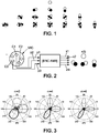
- Ambisonia consists of a projection of the acoustic field on a basis of spherical harmonic functions (basis illustrated on figure 1 ), to obtain a spatial representation of the sound scene.
- a real ambisonic encoding is done from a network of sensors, generally distributed on a sphere, which are combined to synthesize an ambisonic content whose channels best respect the directivities of the spherical harmonics (as illustrated on figure 2 ).
- a MIC microphone comprises a plurality of piezoelectric capsules C1, C2, ... which receive sound waves in different directions of arrival in space.
- a processing unit UT receiving the signals coming from these capsules performs ambisonic encoding using a matrix of filters presented below, and delivers ambisonic signals (formalized in a base of spherical harmonics of the type illustrated on figure 1 ).
- the ambisonic formalism initially limited to the representation of spherical harmonic functions of order 1, was subsequently extended to higher orders.
- the ambisonic formalism with a larger number of components is commonly called “ Higher Order Ambisonics ” (or “HOA” hereafter).
- an M-order content contains a total of (M + 1) 2 channels (4 channels in order 1, 9 channels in order 2, 16 channels in order 3, and so on).
- x (t) of order M and composed of N sound sources s i of incidence ( ⁇ i , ⁇ i ) propagating in a free field
- A is a so-called “mixing matrix”, of dimensions (M + 1) 2 x N and of which each column A i contains the mixing coefficients of the source i .
- this matrix A corresponds to the encoding coefficients of each source i, associated with each direction of each source i .
- a matrix B called the “separation matrix”, the inverse of matrix A.
- ACI independent component analysis algorithm
- This step amounts to forming channels (or “beamforming” hereafter), that is to say to combining different channels having distinct directivities, in order to create a new component having the desired directivity.
- the process is similar.
- s (t) the sum of the contributions of sources
- s (t) the sum of the transmitted signals by a set of loudspeakers (which then makes it possible to supply these loudspeakers effectively with the signals s1, s2, s3, etc.).
- the decoding matrix B is therefore formulated here from the positions of the loudspeakers of a sound reproduction system and the signals intended for the loudspeakers are extracted according to the same process as that used for the separation of sources.
- the sensors used have physical limitations which lead to a degradation of the microphone encoding, and therefore a degradation of the directivity of the ambisonic components.
- the encoding of high frequencies deteriorates when the inter-sensor spacing becomes approximately greater than half a wavelength: this is due to the phenomenon of spatial aliasing.
- the microphone capsules tend to become omnidirectional and it becomes impossible to obtain the desired directivities.
- the degradations at low frequencies are more marked when it comes to synthesizing high order ambisonic components.
- the associated directivities are more complex and therefore more sensitive to variations in the properties of the sensors.
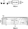
- the figure 5 illustrates the degree of correlation between theoretical encoding and actual encoding from a 32 capsule spherical microphone, as a function of frequency and ambisonic order.
- the figure 5 shows that the highest degree of correlation is generally achieved for frequencies between 1 kHz and 10 kHz. Nevertheless, for the other frequency ranges (except for the ambisonic orders 0 and 1), the extraction of sources would not always lead to the same result for a theoretical encoding and for a real encoding of these same sources. More precisely, for frequencies outside the interval [1 kHz-10 kHz], the extracted components are potentially degraded.
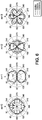
- the figure 6 shows the real directivity in the horizontal plane of the first components of orders 0, 1, 2 and 3 as a function of the sound frequency. It appears, on the figure 6 , that the real components are not properly encoded. Indeed, if we take the example of the component of order 0 at the frequency of 10 kHz, we see that it is not circular, unlike the theoretical component and the same component calculated at frequencies between 300 and 1000Hz. Thus, the directivity of this component at the frequency of 10 kHz is no longer respected, which could induce a degraded spatial rendering. Furthermore, the components at order 1, 2 and 3 also have biased directivities for frequencies lower than 10 kHz.
- the beamforming carried out no longer makes it possible to properly extract the desired components. For example, this results in the appearance of interference during source separation. This can also result in a degradation of the spatial rendering in frequency bands concerned by multichannel broadcasting. More particularly, there is a loss of energy at low frequencies in high orders during encoding. This implies that the sources extracted using high order channels can lose part of their energy in the frequencies concerned.
- the present invention improves this situation.
- a frequency band can be defined by several frequency bands or frequency subbands.
- ambisonic decoding sub-matrices for each frequency band, and for each ambisonic order, makes it possible to take advantage in each frequency band of a maximum number of ambisonic channels which are really valid in each sub-matrix, in order to to restore a decoded signal with little or no degradation.
- each ambisonic decoding sub-matrix is associated with a frequency band chosen as a function of a criterion of validity of the ambisonic components of the order with which said sub-matrix is associated, in said chosen frequency band.
- Such an embodiment makes it possible to isolate the ambisonic components constituting each order, in order to process them in the frequency range in which they are valid.
- the component validity criterion can be defined by conditions for capturing said ambisonic components, by at least one ambisonic microphone.
- a frequency band associated with an ambisonic order can include several FFT frequency bands.
- several frequency bands can be associated with an ambisonic order.
- the processing of the ambisonic content is carried out for source separation and said decoding matrix is a source blind separation matrix constructed from the ambisonic components.
- the separation matrix can be produced from ambisonic components filtered at a chosen frequency band and preferably in which the number of ambisonic channels valid according to the aforementioned criterion is maximum.
- the channels are retained for an accuracy of representation at such a highest ambisonic order, but also to keep a maximum of channels represented correctly in this frequency band, at lower ambisonic orders.
- mixing sub-matrices are simplified before their inversion, by reducing a number of columns of each sub-matrix, the remaining columns of the sub-matrices being chosen so as to keep the least correlated signals. after application of the decoding sub-matrices.
- the signal is made up of direct fields resulting from the equivalent “free field” propagation of each source and reflections on the walls of the acoustic environment.
- mixing sub-matrices are simplified before their inversion, by reducing a number of columns of each sub-matrix, the remaining columns of the sub-matrices being chosen so as to keep signals. corresponding to direct sound fields after application of the decoding sub-matrices.
- the aforementioned decoding matrix can be an inverse matrix of the relative spatial positions of the loudspeakers.
- the present invention is also aimed at a computer program comprising instructions for implementing the method when this program is executed by a processor.
- An example of a flowchart of the general algorithm of such a program is shown in Figure figure 7 commented on below, which is specified in the figures 8 and 9 .
- the present invention thus proposes to use the formation of channels from a real ambisonic encoding by taking advantage, in each frequency band, of all the channels whose directivity respects the ambisonic formalism.
- An embodiment presented above then makes it possible to determine one or more mixing matrices Ak, corresponding to sub-matrices obtained from the theoretical matrix A, and each formulated in a frequency band, then inverted to give matrices of Bk decoding.
- the invention offers a generic processing of any ambisonic content, and in particular real, possibly affected by the physical limitations of a recording system, and this without any constraint aiming to limit the total bandwidth of the extracted sources. .
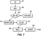
- FIG. 7 The overall diagram of a global ambisonic treatment method within the meaning of the invention is presented figure 7 .
- This is for example an ambisonic decoding process.
- the terms “ambisonic decoding” are understood to mean both the supply of decoded signals, for example intended to supply respective loudspeakers for surround sound reproduction, and more generally the supply of signals each associated with a sound source, especially in the source separation technique.
- An ambisonic microphone is a microphone made up of a plurality of microphone capsules generally distributed in a spherical manner and as regularly as possible. These capsules act as sound signal sensors. The microphone capsules are arranged on the ambisonic microphone so as to pick up sound signals according to their directionality in space.
- Step S2 therefore aims to recover the data characterizing the ambisonic microphone MIC (and possibly the conditions for capturing the ambisonic content c (t), and / or the reverberation conditions during capturing, or the like).
- a data characterizing the ambisonic microphone MIC can be the inter-capsule spacing.
- the encoding of the high frequencies is degraded when the inter-sensor spacing becomes greater than half a wavelength. This is due to the phenomenon of spatial aliasing (or “aliasing”).
- aliasing spatial aliasing
- a BFA analysis filter bank can be applied to the ambisonic content x (t) in order to then select, in step S31, ambisonic component signals filtered in frequency ranges in which the representation ambisonic for a given order m is the most exact (thus respecting a “validity criterion” of the ambisonic representation), and this according to the microphone data defined above.
- step S4 aims to obtain a matrix decoding B, depending on the type of processing chosen.
- the decoding matrix B is the inverse of a matrix A containing coefficients specific to the spatial positions of the loudspeakers used for the reproduction.
- the decoding matrix B is initially produced in step S4 with a view to blind source separation processing from the filtered and selected ambisonic components. More particularly, this decoding matrix B is produced for the frequency band containing the greatest number of valid ambisonic channels (and the greatest order likely to be obtained M).
- the determination of the frequency bands of validity of the various ambisonic orders can be adapted to the ambisonic microphone used to capture the ambisonic components to be decoded. To do this, it is possible for example to base oneself on the frequency variations of the accuracy of the ambisonic representation for different orders m, of the type illustrated on the figure 5 .
- step S7 at least two matrices B1, B2, resulting from a matrix reduction of the decoding matrix B for each frequency sub-band (in the example illustrated, the frequency sub-bands f1 and f2 ).
- a matrix reduction of the decoding matrix B for each frequency sub-band in the example illustrated, the frequency sub-bands f1 and f2 .
- step S8 the product of each matrix B1 and B2 obtained in the previous step is carried out by the ambisonic signals filtered in the corresponding sub-bands f1, f2.
- a set of extracted signals sk is obtained.
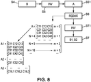
- the figure 8 illustrates the steps of a particular embodiment of the method according to the invention. More precisely, the figure 8 presents process steps which can be implemented between steps S4 and S7 of the figure 7 .
- step S4 as described above, the decoding matrix B defined above is obtained.
- step S5 it is possible to perform an inversion of this decoding matrix B (or in an equivalent manner, a determination of its pseudo-inverse) in order to obtain the corresponding mixing matrix A (step S51).
- the mixing matrix A can thus contain coefficients relating to respective positions of sound sources to be extracted.
- the mixing matrix A can contain coefficients relating to the position of the loudspeakers on which it is desired to reproduce the decoded signals.
- Each mixing sub-matrix thus obtained is of dimension N x Ntarget, with Ntarget the number of sources resulting from the separation of blind sources or the number of loudspeakers provided for a reproduction.
- the number of loudspeakers is preferably equal to or greater than the number of lines.
- the number of columns may be less than or equal to the number of rows.
- the mixing matrix A1 of four rows we can delete columns and keep for example sources whose signals are of greater energies and / or those which are the least correlated (sources less "mixed” possible) and / or the signals correspond to the direct field of the sources, or the like.
- step S71 an inversion of each mixing sub-matrix A1, A2 is carried out in order to obtain respectively the decoding sub-matrices B1, B2 presented above (step S7). Passing through the mixing matrix A makes it possible in particular to conserve satisfactory levels of energy of the ambisonic components linked to each order, despite the matrix reductions. In other words, steps S5 to S71 make it possible to “refine” the decoding of the ambisonic content x (t).
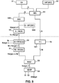
- the figure 9 is a block diagram of a processing algorithm corresponding to the embodiment illustrated in the figures 7 and 8 .
- the same step references S1, S2, etc. have been used to denote identical or similar steps presented above with reference to figures 7 and 8 .
- step S2 the data relating to the ambisonic capture of the content x (t) (data relating to the ambisonic microphone MIC used, etc.) is available.
- a frequency band is determined for each ambisonic order.
- a filter bank allowing reconstruction is applied to the N ambisonic channels in step S3, to give K sub-bands denoted xk.
- the sub-bands are chosen to correspond to the different ranges of validity of the microphone encoding.
- a source separation matrix B is used, developed as a function of the frequency-filtered ambisonic components. (arrow from above coming on rectangle S4A). More particularly, a blind source separation method is applied in the sub-band containing the most valid channels, to obtain a separation matrix B of dimensions Ntarget x N, Ntarget being the number of sources obtained by the blind separation method in the selected frequency sub-band.
- the valid channels are determined on the basis of a validity criterion relating to each order of the ambisonic content x (t) as a function of each frequency band of the filter bank. More generally, in order to maximize the quality of the source separation, a frequency band comprising the most valid ambisonic components is chosen.
- the term “valid” is understood to mean components whose energy criteria or directivity have not been biased during ambisonic capture, as presented above with reference to the. figure 5 .
- each order in frequency bands of the audio domain can be established by knowing the limits of the ambisonic microphone used during the capture of the ambisonic content x (t), or with the help of an abacus established on the basis of measurements carried out on a plurality of ambisonic microphones, making it possible to obtain an average of the validity of each ambisonic order in each frequency band.
- 1st order ambisonics channels tend to be valid in a frequency band ranging from 100Hz to about 10kHz.
- the frequency band in which 2nd order ambisonics can be more generally valid can for example range from 1kHz to 9kHz, etc.
- step S4B the decoding matrix is constructed as a function of the position of the loudspeakers on which the content must be reproduced. More exactly, this decoding matrix B corresponds to the inverse of a mixing matrix A which is defined by the respective spatial positions of the loudspeakers.
- the “theoretical” mixing matrix A (for the two aforementioned variants) is constructed by inversion of B.
- the mixing matrix is made up of N rows and Ntarget columns, the ith column containing the spherical harmonic coefficients, relating to the coordinates ( ⁇ i , ⁇ i ) of the source s i .
- a mixing matrix A in the case of source separation for ambisonic content of order 2 composed of five sources:
- A is composed of N lines and a minimum of N columns, the ith column containing the spherical harmonic coefficients, relating to the coordinates ( ⁇ i , ⁇ i ) of the loudspeaker i.
- step S6 and for each sub-band k, a mixing sub-matrix Ak is constructed, such that Ak is a truncated version of the matrix A, by keeping only the Nk rows corresponding to the channels effectively valid in this subband k.
- Nk is less than the number of sources Ntarget sought in the sub-band, only one set of Ntarget, k, columns (with Ntarget, k less than or equal to Nk), chosen according to energy criteria (for example by separating the sources with the greatest contribution) or according to other criteria of interest as defined previously.
- Ak (4x4) matrix truncated to order 1 ambisonic
- a set of Nk loudspeakers is selected for reproduction, and Ak therefore has the dimensions Nk x Nk.
- step S7 the matrix Ak is inverted to give Bk.
- the sub-matrix Ak is not a square matrix, an infinite number of possibilities exist for the inversion.
- a pseudo-inversion can be applied, or else an inversion by applying additional constraints (for example choice of the solution giving the most directional beamforming, or minimizing the secondary lobes).
- matrix inversion is understood to mean both a conventional matrix inversion and a pseudo-inversion as presented above.
- a filter bank is implemented, consisting of two frequency bands, 200Hz-900Hz (up to order 1) and 900Hz-8000Hz (use of order 2)
- x1 (t) consists of 4 channels (order 1 ambisonics) and x2 (t) contains 9 channels (order 2 ambisonics).
- a separation matrix B of dimensions 3x9 is estimated by independent component analysis carried out in the 900Hz-8000Hz sub-band, that is to say x2 (t).
- a theoretical mixing matrix A of dimensions 9x3, is deduced by inversion of B, each column i containing the spherical harmonic coefficients of the source i.
- A1 and A2 are inverted to form the separation matrices B1 and B2.
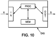
- the present invention further relates to a DIS device for implementing the invention.
- This DIS device can include an input interface IN to receive ambisonic signals x (t).
- the device DIS can comprise a memory MEM for storing instructions of a computer program within the meaning of the invention.
- the instructions of the computer program are instructions for processing the ambisonic signals x (t). They are implemented by a processor PROC, in order to deliver, via an output interface OUT, decoded signals s (t).
- the frequency ranges for which the ambisonic representation is valid are given above by way of example and may differ depending on the nature of the ambisonic microphone (s) used for pickup, or even the pickup conditions themselves.
Landscapes
- Engineering & Computer Science (AREA)
- Physics & Mathematics (AREA)
- Acoustics & Sound (AREA)
- Signal Processing (AREA)
- Multimedia (AREA)
- Computational Linguistics (AREA)
- Human Computer Interaction (AREA)
- Audiology, Speech & Language Pathology (AREA)
- Health & Medical Sciences (AREA)
- Quality & Reliability (AREA)
- Mathematical Physics (AREA)
- Mathematical Analysis (AREA)
- Theoretical Computer Science (AREA)
- Pure & Applied Mathematics (AREA)
- Mathematical Optimization (AREA)
- General Physics & Mathematics (AREA)
- Algebra (AREA)
- Stereophonic System (AREA)
- Circuit For Audible Band Transducer (AREA)
Claims (15)
- Verfahren, welches von Informatikmitteln durchgeführt wird, zur Verarbeitung esines Ambisonic-Inhalts, der mehrere Ambisonic-Komponenten mehrerer Ordnungen umfasst, die eine Folge von Ambisonic-Kanälen definieren, in denen jeweils eine Ambisonic-Komponente dargestellt wird, wobei das Verfahren umfasst:- eine Frequenzfilterung der Ambisonic-Komponenten in mehrere Frequenzbänder,- eine Erstellung einer Ambisonic-Decodiermatrix (B), wobei das Verfahren gekennzeichnet ist durch:- eine Verarbeitung der Ambisonic-Decodiermatrix (B), um durch Verringerung der Matrixdimension mehrere Ambisonic-Decodierungs-Untermatrizen (B1, B2) zu extrahieren, die jeweils einer Ambisonic-Ordnung und einem für diese Ambisonic-Ordnung gewählten Frequenzband zugeordnet sind,- jeweilige Anwendungen der Decodierungs-Untermatrizen auf die Ambisonic-Komponenten in jedem gewählten Frequenzband und eine Rekonstruktion, Band für Band, der Ergebnisse dieser jeweiligen Anwendungen, um mehrere decodierte Signale zu liefern, die jeweils einer Schallquelle zugeordnet sind.
- Verfahren nach Anspruch 1, wobei jede Untermatrix einem Frequenzband zugeordnet wird, das in Abhängigkeit von einem Kriterium der Gültigkeit der Ambisonic-Komponenten der Ordnung, welcher die Untermatrix zugeordnet ist, in dem gewählten Frequenzband gewählt wird.
- Verfahren nach Anspruch 2, wobei das Kriterium der Gültigkeit der Komponenten durch Bedingungen der Erfassung dieser Ambisonic-Komponenten durch mindestens ein Ambisonic-Mikrofon definiert ist.
- Verfahren nach Anspruch 3, welches umfasst:- einen Empfang von Daten von mindestens einem Ambisonic-Mikrofon, das verwendet wird, um die Ambisonic-Komponenten zu erfassen;- eine Bestimmung der Frequenzbänder, die gewählt werden, um die Untermatrizen (B1, B2) zu konstruieren, in Abhängigkeit von den Daten des Ambisonic-Mikrofons.
- Verfahren nach einem der vorhergehenden Ansprüche, wobei, wenn jede Ambisonic-Decodierungs-Untermatrix (B1, B2) einer Ambisonic-Ordnung und einem für diese Ambisonic-Ordnung gewählten Frequenzband zugeordnet ist,- ein Frequenzband in einem Bereich von 100 Hz bis 10 kHz für die Ambisonic-Ordnung m = 1 gewählt wird,- ein Frequenzband in einem Bereich von 500 Hz bis 10 kHz für die Ambisonic-Ordnung m = 2 gewählt wird,- ein Frequenzband in einem Bereich von 2000 Hz bis 9000 Hz für die Ambisonic-Ordnung m = 3 gewählt wird,- ein Frequenzband in einem Bereich von 3000 Hz bis 7000 Hz für die Ambisonic-Ordnung m = 4 gewählt wird.
- Verfahren nach einem der vorhergehenden Ansprüche, wobei die Verarbeitung der Ambisonic-Decodiermatrix (B) umfasst:- eine Invertierung der erstellten Ambisonic-Decodiermatrix (B), um eine Mischmatrix (A) zu erhalten, in der:• die Zeilen jeweiligen Ambisonic-Kanälen entsprechen, und• die Spalten Schallquellen entsprechen,- eine Verarbeitung der Mischmatrix (A), um durch Verringerung der Matrixdimension mehrere Misch-Untermatrizen (A1, A2) zu extrahieren, die jeweils einer Ambisonic-Ordnung und einem gewählten Frequenzband zugeordnet sind, und- eine Invertierung der Misch-Untermatrizen (A1, A2), um jeweils die Ambisonic-Decodierungs-Untermatrizen (B1, B2) zu erhalten.
- Verfahren nach einem der vorhergehenden Ansprüche, wobei die Verarbeitung des Ambisonic-Inhalts für eine Quellentrennung durchgeführt wird und die Decodiermatrix (B) eine Matrix der blinden Quellentrennung ist, die aus den Ambisonic-Komponenten erstellt wird (S4A).
- Verfahren nach Anspruch 7 in Verbindung mit Anspruch 2, wobei die Trennmatrix (B) aus den in einem gewählten Frequenzband gefilterten Ambisonic-Komponenten erstellt wird, und wobei die Anzahl der gemäß dem Kriterium gültigen Ambisonic-Kanäle maximal ist.
- Verfahren nach einem der Ansprüche 7 und 8 in Verbindung mit Anspruch 6, welches außerdem eine Vereinfachung der Misch-Untermatrizen (A1, A2) vor ihrer Invertierung durch Verringerung einer Spaltenzahl jeder Untermatrix umfasst, wobei die verbleibenden Spalten der Untermatrizen so gewählt werden, dass nach Anwendung der Decodierungs-Untermatrizen Signale mit den größten Energien erhalten bleiben.
- Verfahren nach einem der Ansprüche 7 bis 9 in Verbindung mit Anspruch 6, welches außerdem eine Vereinfachung der Misch-Untermatrizen (A1, A2) vor ihrer Invertierung durch Verringerung einer Spaltenzahl jeder Untermatrix umfasst, wobei die verbleibenden Spalten der Untermatrizen so gewählt werden, dass nach Anwendung der Decodierungs-Untermatrizen Signale, die am wenigsten korreliert sind, erhalten bleiben.
- Verfahren nach einem der Ansprüche 7 bis 10 in Verbindung mit Anspruch 6, welches außerdem eine Vereinfachung der Misch-Untermatrizen (A1, A2) vor ihrer Invertierung durch Verringerung einer Spaltenzahl jeder Untermatrix umfasst, wobei die verbleibenden Spalten der Untermatrizen so gewählt werden, dass nach Anwendung der Decodierungs-Untermatrizen Signale, die direkten Schallfeldern entsprechen, erhalten bleiben.
- Verfahren nach einem der Ansprüche 1 bis 6, wobei die Verarbeitung des Ambisonic-Inhalts für eine Ambisonic-Wiedergabe auf mehreren Lautsprechern durchgeführt wird und die Decodiermatrix (B) eine inverse Matrix relativer räumlicher Positionen der Lautsprecher ist (S4B).
- Verfahren nach einem der vorhergehenden Ansprüche, welches für einen in Teilfrequenzbänder (k) zerlegten Ambisonic-Inhalt (x) eine Anwendung von Decodierungs-Untermatrizen (Bk) umfasst, die erhalten wurden durch:- für jede Ambisonic-Ordnung des Inhalts, eine Bestimmung eines Frequenzbandes, auf welchem die Ordnung ein vorbestimmtes Gültigkeitskriterium der Ambisonic-Codierung einhält,- auf der Basis dieser Frequenzbänder, eine Anwendung einer Filterbank auf den Ambisonic-Inhalt (x), um mehrere Signale in Teilbändern (xk) mit variablen Größen zu erzeugen, welche Ambisonic-Kanälen entsprechen, die in diesem Teilband (k) gültig sind,- eine Bestimmung einer Decodiermatrix (B) von maximaler Größe in dem Frequenzband der maximalen Ambisonic-Ordnung und einer zugeordneten Mischmatrix (A), die invers oder pseudoinvers zu der Decodiermatrix (B) ist,- für jedes andere Frequenzband (k), eine Bestimmung einer Mischmatrix (Ak) von reduzierter Größe, die eine Untermatrix der Mischmatrix (A) ist, und einer Decodierungs-Untermatrix (Bk), die invers oder pseudoinvers zu der Misch-Untermatrix (Ak) ist,- eine Rekonstruktion der getrennten Vollbandsignale (s) durch Anwendung einer Synthesefilterbank auf die getrennten Signale (sk), die aus der Multiplikation der Signale (xk) mit den Matrizen (Bk) hervorgehen.
- Computerprogramm, dadurch gekennzeichnet, dass es Anwendungen zur Durchführung des Verfahrens nach einem der Ansprüche 1 bis 13, wenn dieses Programm von einem Prozessor ausgeführt wird, umfasst.
- Rechenvorrichtung, welche umfasst:- eine Eingangsschnittstelle zum Empfangen von Signalen von Ambisonic-Komponenten,- eine Ausgangsschnittstelle zum Liefern von decodierten Signalen, die jeweils einer Schallquelle zugeordnet sind,- und eine Verarbeitungsschaltung, die für die Durchführung des Verfahrens nach einem der Ansprüche 1 bis 13 ausgelegt ist.
Applications Claiming Priority (2)
| Application Number | Priority Date | Filing Date | Title |
|---|---|---|---|
| FR1663079A FR3060830A1 (fr) | 2016-12-21 | 2016-12-21 | Traitement en sous-bandes d'un contenu ambisonique reel pour un decodage perfectionne |
| PCT/FR2017/053622 WO2018115666A1 (fr) | 2016-12-21 | 2017-12-15 | Traitement en sous-bandes d'un contenu ambisonique réel pour un décodage perfectionné |
Publications (2)
| Publication Number | Publication Date |
|---|---|
| EP3559947A1 EP3559947A1 (de) | 2019-10-30 |
| EP3559947B1 true EP3559947B1 (de) | 2020-09-02 |
Family
ID=58162877
Family Applications (1)
| Application Number | Title | Priority Date | Filing Date |
|---|---|---|---|
| EP17829231.4A Active EP3559947B1 (de) | 2016-12-21 | 2017-12-15 | Verarbeitung in subbändern eines aktuellen ambisonic-inhalts zur verbesserten dekodierung |
Country Status (6)
| Country | Link |
|---|---|
| US (1) | US10687164B2 (de) |
| EP (1) | EP3559947B1 (de) |
| CN (1) | CN110301003B (de) |
| ES (1) | ES2834087T3 (de) |
| FR (1) | FR3060830A1 (de) |
| WO (1) | WO2018115666A1 (de) |
Families Citing this family (4)
| Publication number | Priority date | Publication date | Assignee | Title |
|---|---|---|---|---|
| GB201818959D0 (en) * | 2018-11-21 | 2019-01-09 | Nokia Technologies Oy | Ambience audio representation and associated rendering |
| CN117809663A (zh) | 2018-12-07 | 2024-04-02 | 弗劳恩霍夫应用研究促进协会 | 从包括至少两个声道的信号产生声场描述的装置、方法 |
| FR3096550B1 (fr) | 2019-06-24 | 2021-06-04 | Orange | Dispositif de captation sonore à réseau de microphones perfectionné |
| FR3112016B1 (fr) * | 2020-06-30 | 2023-04-14 | Fond B Com | Procédé de conversion d’un premier ensemble de signaux représentatifs d’un champ sonore en un second ensemble de signaux et dispositif électronique associé |
Family Cites Families (11)
| Publication number | Priority date | Publication date | Assignee | Title |
|---|---|---|---|---|
| FR2847376B1 (fr) * | 2002-11-19 | 2005-02-04 | France Telecom | Procede de traitement de donnees sonores et dispositif d'acquisition sonore mettant en oeuvre ce procede |
| US8290782B2 (en) * | 2008-07-24 | 2012-10-16 | Dts, Inc. | Compression of audio scale-factors by two-dimensional transformation |
| WO2010076460A1 (fr) * | 2008-12-15 | 2010-07-08 | France Telecom | Codage perfectionne de signaux audionumériques multicanaux |
| EP2469741A1 (de) * | 2010-12-21 | 2012-06-27 | Thomson Licensing | Verfahren und Vorrichtung zur Kodierung und Dekodierung aufeinanderfolgender Rahmen einer Ambisonics-Darstellung eines 2- oder 3-dimensionalen Schallfelds |
| EP2592846A1 (de) * | 2011-11-11 | 2013-05-15 | Thomson Licensing | Verfahren und Vorrichtung zur Verarbeitung von Signalen einer kugelförmigen Mikrofonanordnung auf einer starren Kugel zur Erzeugung einer Ambisonics-Wiedergabe des Klangfelds |
| EP2866475A1 (de) * | 2013-10-23 | 2015-04-29 | Thomson Licensing | Verfahren und Vorrichtung zur Decodierung einer Audioschallfelddarstellung für Audiowiedergabe mittels 2D-Einstellungen |
| CN104754471A (zh) * | 2013-12-30 | 2015-07-01 | 华为技术有限公司 | 基于麦克风阵列的声场处理方法和电子设备 |
| KR101862356B1 (ko) * | 2014-01-03 | 2018-06-29 | 삼성전자주식회사 | 개선된 앰비소닉 디코딩을 수행하는 방법 및 장치 |
| US9838819B2 (en) * | 2014-07-02 | 2017-12-05 | Qualcomm Incorporated | Reducing correlation between higher order ambisonic (HOA) background channels |
| EP3007167A1 (de) * | 2014-10-10 | 2016-04-13 | Thomson Licensing | Verfahren und Vorrichtung zur Komprimierung mit niedrigen Kompressions-Datenraten einer übergeordneten Ambisonics-Signalrepräsentation eines Schallfelds |
| US9712936B2 (en) * | 2015-02-03 | 2017-07-18 | Qualcomm Incorporated | Coding higher-order ambisonic audio data with motion stabilization |
-
2016
- 2016-12-21 FR FR1663079A patent/FR3060830A1/fr not_active Withdrawn
-
2017
- 2017-12-15 ES ES17829231T patent/ES2834087T3/es active Active
- 2017-12-15 EP EP17829231.4A patent/EP3559947B1/de active Active
- 2017-12-15 US US16/471,371 patent/US10687164B2/en active Active
- 2017-12-15 WO PCT/FR2017/053622 patent/WO2018115666A1/fr not_active Ceased
- 2017-12-15 CN CN201780079018.7A patent/CN110301003B/zh active Active
Non-Patent Citations (1)
| Title |
|---|
| None * |
Also Published As
| Publication number | Publication date |
|---|---|
| US20190335291A1 (en) | 2019-10-31 |
| ES2834087T3 (es) | 2021-06-16 |
| CN110301003B (zh) | 2023-04-21 |
| EP3559947A1 (de) | 2019-10-30 |
| WO2018115666A1 (fr) | 2018-06-28 |
| CN110301003A (zh) | 2019-10-01 |
| FR3060830A1 (fr) | 2018-06-22 |
| US10687164B2 (en) | 2020-06-16 |
Similar Documents
| Publication | Publication Date | Title |
|---|---|---|
| EP1992198B1 (de) | Optimierung des binauralen raumklangeffektes durch mehrkanalkodierung | |
| EP2898707B1 (de) | Optimierte kalibrierung eines klangwiedergabesystems mit mehreren lautsprechern | |
| EP2374124B1 (de) | Verwaltete codierung von mehrkanaligen digitalen audiosignalen | |
| EP3635718B1 (de) | Verarbeitung von klangdaten zur trennung von klangquellen in einem mehrkanalsignal | |
| EP2002424B1 (de) | Vorrichtung und verfahren zur skalierbaren kodierung eines mehrkanaligen audiosignals auf der basis einer hauptkomponentenanalyse | |
| EP2005420B1 (de) | Einrichtung und verfahren zur codierung durch hauptkomponentenanalyse eines mehrkanaligen audiosignals | |
| EP1600042B1 (de) | Verfahren zum bearbeiten komprimierter audiodaten zur räumlichen wiedergabe | |
| EP3391370B1 (de) | Adaptive kanalreduktionsverarbeitung zur codierung eines mehrkanalaudiosignals | |
| EP3559947B1 (de) | Verarbeitung in subbändern eines aktuellen ambisonic-inhalts zur verbesserten dekodierung | |
| EP3427260B1 (de) | Optimierte codierung und decodierung von verräumlichungsinformationen zur parametrischen codierung und decodierung eines mehrkanaligen audiosignals | |
| EP2901718B1 (de) | Verfahren und vorrichtung zur wiedergabe eines audiosignals | |
| EP2319037B1 (de) | Rekonstruktion von mehrkanal-audiodaten | |
| WO2007110520A1 (fr) | Procede de synthese binaurale prenant en compte un effet de salle | |
| FR3065137A1 (fr) | Procede de spatialisation sonore | |
| EP3025514B1 (de) | Klangverräumlichung mit raumwirkung | |
| EP3058564B1 (de) | Komplexitätsoptimierte klangverräumlichung mit nachhall | |
| EP4042418B1 (de) | Bestimmung von korrekturen zur anwendung auf ein mehrkanalaudiosignal, zugehörige codierung und decodierung | |
| EP3384688B1 (de) | Aufeinanderfolgende dekompositionen von audiofiltern | |
| CN121099251A (zh) | 音频的虚拟环绕处理方法、计算机程序产品及电子设备 | |
| WO2017187053A1 (fr) | Procédé et système de diffusion d'un signal audio à 360° |
Legal Events
| Date | Code | Title | Description |
|---|---|---|---|
| STAA | Information on the status of an ep patent application or granted ep patent |
Free format text: STATUS: UNKNOWN |
|
| STAA | Information on the status of an ep patent application or granted ep patent |
Free format text: STATUS: THE INTERNATIONAL PUBLICATION HAS BEEN MADE |
|
| PUAI | Public reference made under article 153(3) epc to a published international application that has entered the european phase |
Free format text: ORIGINAL CODE: 0009012 |
|
| STAA | Information on the status of an ep patent application or granted ep patent |
Free format text: STATUS: REQUEST FOR EXAMINATION WAS MADE |
|
| 17P | Request for examination filed |
Effective date: 20190621 |
|
| AK | Designated contracting states |
Kind code of ref document: A1 Designated state(s): AL AT BE BG CH CY CZ DE DK EE ES FI FR GB GR HR HU IE IS IT LI LT LU LV MC MK MT NL NO PL PT RO RS SE SI SK SM TR |
|
| AX | Request for extension of the european patent |
Extension state: BA ME |
|
| DAV | Request for validation of the european patent (deleted) | ||
| DAX | Request for extension of the european patent (deleted) | ||
| GRAP | Despatch of communication of intention to grant a patent |
Free format text: ORIGINAL CODE: EPIDOSNIGR1 |
|
| STAA | Information on the status of an ep patent application or granted ep patent |
Free format text: STATUS: GRANT OF PATENT IS INTENDED |
|
| INTG | Intention to grant announced |
Effective date: 20200414 |
|
| RAP1 | Party data changed (applicant data changed or rights of an application transferred) |
Owner name: ORANGE |
|
| GRAS | Grant fee paid |
Free format text: ORIGINAL CODE: EPIDOSNIGR3 |
|
| GRAJ | Information related to disapproval of communication of intention to grant by the applicant or resumption of examination proceedings by the epo deleted |
Free format text: ORIGINAL CODE: EPIDOSDIGR1 |
|
| GRAL | Information related to payment of fee for publishing/printing deleted |
Free format text: ORIGINAL CODE: EPIDOSDIGR3 |
|
| STAA | Information on the status of an ep patent application or granted ep patent |
Free format text: STATUS: REQUEST FOR EXAMINATION WAS MADE |
|
| GRAR | Information related to intention to grant a patent recorded |
Free format text: ORIGINAL CODE: EPIDOSNIGR71 |
|
| STAA | Information on the status of an ep patent application or granted ep patent |
Free format text: STATUS: GRANT OF PATENT IS INTENDED |
|
| GRAA | (expected) grant |
Free format text: ORIGINAL CODE: 0009210 |
|
| STAA | Information on the status of an ep patent application or granted ep patent |
Free format text: STATUS: THE PATENT HAS BEEN GRANTED |
|
| INTC | Intention to grant announced (deleted) | ||
| AK | Designated contracting states |
Kind code of ref document: B1 Designated state(s): AL AT BE BG CH CY CZ DE DK EE ES FI FR GB GR HR HU IE IS IT LI LT LU LV MC MK MT NL NO PL PT RO RS SE SI SK SM TR |
|
| INTG | Intention to grant announced |
Effective date: 20200727 |
|
| REG | Reference to a national code |
Ref country code: GB Ref legal event code: FG4D Free format text: NOT ENGLISH |
|
| REG | Reference to a national code |
Ref country code: AT Ref legal event code: REF Ref document number: 1309744 Country of ref document: AT Kind code of ref document: T Effective date: 20200915 Ref country code: CH Ref legal event code: EP |
|
| REG | Reference to a national code |
Ref country code: DE Ref legal event code: R096 Ref document number: 602017023022 Country of ref document: DE |
|
| REG | Reference to a national code |
Ref country code: IE Ref legal event code: FG4D Free format text: LANGUAGE OF EP DOCUMENT: FRENCH |
|
| REG | Reference to a national code |
Ref country code: LT Ref legal event code: MG4D |
|
| PG25 | Lapsed in a contracting state [announced via postgrant information from national office to epo] |
Ref country code: SE Free format text: LAPSE BECAUSE OF FAILURE TO SUBMIT A TRANSLATION OF THE DESCRIPTION OR TO PAY THE FEE WITHIN THE PRESCRIBED TIME-LIMIT Effective date: 20200902 Ref country code: FI Free format text: LAPSE BECAUSE OF FAILURE TO SUBMIT A TRANSLATION OF THE DESCRIPTION OR TO PAY THE FEE WITHIN THE PRESCRIBED TIME-LIMIT Effective date: 20200902 Ref country code: GR Free format text: LAPSE BECAUSE OF FAILURE TO SUBMIT A TRANSLATION OF THE DESCRIPTION OR TO PAY THE FEE WITHIN THE PRESCRIBED TIME-LIMIT Effective date: 20201203 Ref country code: BG Free format text: LAPSE BECAUSE OF FAILURE TO SUBMIT A TRANSLATION OF THE DESCRIPTION OR TO PAY THE FEE WITHIN THE PRESCRIBED TIME-LIMIT Effective date: 20201202 Ref country code: NO Free format text: LAPSE BECAUSE OF FAILURE TO SUBMIT A TRANSLATION OF THE DESCRIPTION OR TO PAY THE FEE WITHIN THE PRESCRIBED TIME-LIMIT Effective date: 20201202 Ref country code: LT Free format text: LAPSE BECAUSE OF FAILURE TO SUBMIT A TRANSLATION OF THE DESCRIPTION OR TO PAY THE FEE WITHIN THE PRESCRIBED TIME-LIMIT Effective date: 20200902 Ref country code: HR Free format text: LAPSE BECAUSE OF FAILURE TO SUBMIT A TRANSLATION OF THE DESCRIPTION OR TO PAY THE FEE WITHIN THE PRESCRIBED TIME-LIMIT Effective date: 20200902 |
|
| REG | Reference to a national code |
Ref country code: NL Ref legal event code: MP Effective date: 20200902 |
|
| REG | Reference to a national code |
Ref country code: AT Ref legal event code: MK05 Ref document number: 1309744 Country of ref document: AT Kind code of ref document: T Effective date: 20200902 |
|
| PG25 | Lapsed in a contracting state [announced via postgrant information from national office to epo] |
Ref country code: PL Free format text: LAPSE BECAUSE OF FAILURE TO SUBMIT A TRANSLATION OF THE DESCRIPTION OR TO PAY THE FEE WITHIN THE PRESCRIBED TIME-LIMIT Effective date: 20200902 Ref country code: RS Free format text: LAPSE BECAUSE OF FAILURE TO SUBMIT A TRANSLATION OF THE DESCRIPTION OR TO PAY THE FEE WITHIN THE PRESCRIBED TIME-LIMIT Effective date: 20200902 Ref country code: LV Free format text: LAPSE BECAUSE OF FAILURE TO SUBMIT A TRANSLATION OF THE DESCRIPTION OR TO PAY THE FEE WITHIN THE PRESCRIBED TIME-LIMIT Effective date: 20200902 |
|
| PG25 | Lapsed in a contracting state [announced via postgrant information from national office to epo] |
Ref country code: CZ Free format text: LAPSE BECAUSE OF FAILURE TO SUBMIT A TRANSLATION OF THE DESCRIPTION OR TO PAY THE FEE WITHIN THE PRESCRIBED TIME-LIMIT Effective date: 20200902 Ref country code: RO Free format text: LAPSE BECAUSE OF FAILURE TO SUBMIT A TRANSLATION OF THE DESCRIPTION OR TO PAY THE FEE WITHIN THE PRESCRIBED TIME-LIMIT Effective date: 20200902 Ref country code: PT Free format text: LAPSE BECAUSE OF FAILURE TO SUBMIT A TRANSLATION OF THE DESCRIPTION OR TO PAY THE FEE WITHIN THE PRESCRIBED TIME-LIMIT Effective date: 20210104 Ref country code: EE Free format text: LAPSE BECAUSE OF FAILURE TO SUBMIT A TRANSLATION OF THE DESCRIPTION OR TO PAY THE FEE WITHIN THE PRESCRIBED TIME-LIMIT Effective date: 20200902 Ref country code: SM Free format text: LAPSE BECAUSE OF FAILURE TO SUBMIT A TRANSLATION OF THE DESCRIPTION OR TO PAY THE FEE WITHIN THE PRESCRIBED TIME-LIMIT Effective date: 20200902 |
|
| PG25 | Lapsed in a contracting state [announced via postgrant information from national office to epo] |
Ref country code: AL Free format text: LAPSE BECAUSE OF FAILURE TO SUBMIT A TRANSLATION OF THE DESCRIPTION OR TO PAY THE FEE WITHIN THE PRESCRIBED TIME-LIMIT Effective date: 20200902 Ref country code: AT Free format text: LAPSE BECAUSE OF FAILURE TO SUBMIT A TRANSLATION OF THE DESCRIPTION OR TO PAY THE FEE WITHIN THE PRESCRIBED TIME-LIMIT Effective date: 20200902 Ref country code: IS Free format text: LAPSE BECAUSE OF FAILURE TO SUBMIT A TRANSLATION OF THE DESCRIPTION OR TO PAY THE FEE WITHIN THE PRESCRIBED TIME-LIMIT Effective date: 20210102 |
|
| REG | Reference to a national code |
Ref country code: DE Ref legal event code: R097 Ref document number: 602017023022 Country of ref document: DE |
|
| REG | Reference to a national code |
Ref country code: ES Ref legal event code: FG2A Ref document number: 2834087 Country of ref document: ES Kind code of ref document: T3 Effective date: 20210616 |
|
| PG25 | Lapsed in a contracting state [announced via postgrant information from national office to epo] |
Ref country code: SK Free format text: LAPSE BECAUSE OF FAILURE TO SUBMIT A TRANSLATION OF THE DESCRIPTION OR TO PAY THE FEE WITHIN THE PRESCRIBED TIME-LIMIT Effective date: 20200902 |
|
| PLBE | No opposition filed within time limit |
Free format text: ORIGINAL CODE: 0009261 |
|
| STAA | Information on the status of an ep patent application or granted ep patent |
Free format text: STATUS: NO OPPOSITION FILED WITHIN TIME LIMIT |
|
| RAP4 | Party data changed (patent owner data changed or rights of a patent transferred) |
Owner name: ORANGE |
|
| REG | Reference to a national code |
Ref country code: CH Ref legal event code: PL |
|
| 26N | No opposition filed |
Effective date: 20210603 |
|
| PG25 | Lapsed in a contracting state [announced via postgrant information from national office to epo] |
Ref country code: MC Free format text: LAPSE BECAUSE OF FAILURE TO SUBMIT A TRANSLATION OF THE DESCRIPTION OR TO PAY THE FEE WITHIN THE PRESCRIBED TIME-LIMIT Effective date: 20200902 Ref country code: DK Free format text: LAPSE BECAUSE OF FAILURE TO SUBMIT A TRANSLATION OF THE DESCRIPTION OR TO PAY THE FEE WITHIN THE PRESCRIBED TIME-LIMIT Effective date: 20200902 |
|
| REG | Reference to a national code |
Ref country code: BE Ref legal event code: MM Effective date: 20201231 |
|
| PG25 | Lapsed in a contracting state [announced via postgrant information from national office to epo] |
Ref country code: IE Free format text: LAPSE BECAUSE OF NON-PAYMENT OF DUE FEES Effective date: 20201215 Ref country code: LU Free format text: LAPSE BECAUSE OF NON-PAYMENT OF DUE FEES Effective date: 20201215 |
|
| PG25 | Lapsed in a contracting state [announced via postgrant information from national office to epo] |
Ref country code: LI Free format text: LAPSE BECAUSE OF NON-PAYMENT OF DUE FEES Effective date: 20201231 Ref country code: CH Free format text: LAPSE BECAUSE OF NON-PAYMENT OF DUE FEES Effective date: 20201231 |
|
| PG25 | Lapsed in a contracting state [announced via postgrant information from national office to epo] |
Ref country code: TR Free format text: LAPSE BECAUSE OF FAILURE TO SUBMIT A TRANSLATION OF THE DESCRIPTION OR TO PAY THE FEE WITHIN THE PRESCRIBED TIME-LIMIT Effective date: 20200902 Ref country code: MT Free format text: LAPSE BECAUSE OF FAILURE TO SUBMIT A TRANSLATION OF THE DESCRIPTION OR TO PAY THE FEE WITHIN THE PRESCRIBED TIME-LIMIT Effective date: 20200902 Ref country code: CY Free format text: LAPSE BECAUSE OF FAILURE TO SUBMIT A TRANSLATION OF THE DESCRIPTION OR TO PAY THE FEE WITHIN THE PRESCRIBED TIME-LIMIT Effective date: 20200902 |
|
| PG25 | Lapsed in a contracting state [announced via postgrant information from national office to epo] |
Ref country code: MK Free format text: LAPSE BECAUSE OF FAILURE TO SUBMIT A TRANSLATION OF THE DESCRIPTION OR TO PAY THE FEE WITHIN THE PRESCRIBED TIME-LIMIT Effective date: 20200902 |
|
| PG25 | Lapsed in a contracting state [announced via postgrant information from national office to epo] |
Ref country code: BE Free format text: LAPSE BECAUSE OF NON-PAYMENT OF DUE FEES Effective date: 20201231 |
|
| PG25 | Lapsed in a contracting state [announced via postgrant information from national office to epo] |
Ref country code: NL Free format text: LAPSE BECAUSE OF NON-PAYMENT OF DUE FEES Effective date: 20200923 |
|
| PG25 | Lapsed in a contracting state [announced via postgrant information from national office to epo] |
Ref country code: SI Free format text: LAPSE BECAUSE OF FAILURE TO SUBMIT A TRANSLATION OF THE DESCRIPTION OR TO PAY THE FEE WITHIN THE PRESCRIBED TIME-LIMIT Effective date: 20200902 |
|
| PGFP | Annual fee paid to national office [announced via postgrant information from national office to epo] |
Ref country code: DE Payment date: 20251126 Year of fee payment: 9 |
|
| PGFP | Annual fee paid to national office [announced via postgrant information from national office to epo] |
Ref country code: GB Payment date: 20251119 Year of fee payment: 9 |
|
| PGFP | Annual fee paid to national office [announced via postgrant information from national office to epo] |
Ref country code: IT Payment date: 20251119 Year of fee payment: 9 |
|
| PGFP | Annual fee paid to national office [announced via postgrant information from national office to epo] |
Ref country code: FR Payment date: 20251119 Year of fee payment: 9 |
|
| PGFP | Annual fee paid to national office [announced via postgrant information from national office to epo] |
Ref country code: ES Payment date: 20260102 Year of fee payment: 9 |