EP3559900B1 - Système et procédé de compensation de réflexion sur un dispositif d'affichage - Google Patents
Système et procédé de compensation de réflexion sur un dispositif d'affichage Download PDFInfo
- Publication number
- EP3559900B1 EP3559900B1 EP17883609.4A EP17883609A EP3559900B1 EP 3559900 B1 EP3559900 B1 EP 3559900B1 EP 17883609 A EP17883609 A EP 17883609A EP 3559900 B1 EP3559900 B1 EP 3559900B1
- Authority
- EP
- European Patent Office
- Prior art keywords
- reflection
- display device
- target image
- scene
- luminance values
- Prior art date
- Legal status (The legal status is an assumption and is not a legal conclusion. Google has not performed a legal analysis and makes no representation as to the accuracy of the status listed.)
- Active
Links
Images


Classifications
-
- G—PHYSICS
- G09—EDUCATION; CRYPTOGRAPHY; DISPLAY; ADVERTISING; SEALS
- G09G—ARRANGEMENTS OR CIRCUITS FOR CONTROL OF INDICATING DEVICES USING STATIC MEANS TO PRESENT VARIABLE INFORMATION
- G09G5/00—Control arrangements or circuits for visual indicators common to cathode-ray tube indicators and other visual indicators
- G09G5/10—Intensity circuits
-
- G—PHYSICS
- G06—COMPUTING OR CALCULATING; COUNTING
- G06T—IMAGE DATA PROCESSING OR GENERATION, IN GENERAL
- G06T5/00—Image enhancement or restoration
- G06T5/90—Dynamic range modification of images or parts thereof
- G06T5/94—Dynamic range modification of images or parts thereof based on local image properties, e.g. for local contrast enhancement
-
- G—PHYSICS
- G06—COMPUTING OR CALCULATING; COUNTING
- G06T—IMAGE DATA PROCESSING OR GENERATION, IN GENERAL
- G06T5/00—Image enhancement or restoration
- G06T5/50—Image enhancement or restoration using two or more images, e.g. averaging or subtraction
-
- G—PHYSICS
- G06—COMPUTING OR CALCULATING; COUNTING
- G06T—IMAGE DATA PROCESSING OR GENERATION, IN GENERAL
- G06T7/00—Image analysis
- G06T7/50—Depth or shape recovery
- G06T7/514—Depth or shape recovery from specularities
-
- G—PHYSICS
- G06—COMPUTING OR CALCULATING; COUNTING
- G06T—IMAGE DATA PROCESSING OR GENERATION, IN GENERAL
- G06T7/00—Image analysis
- G06T7/50—Depth or shape recovery
- G06T7/55—Depth or shape recovery from multiple images
-
- G—PHYSICS
- G06—COMPUTING OR CALCULATING; COUNTING
- G06T—IMAGE DATA PROCESSING OR GENERATION, IN GENERAL
- G06T7/00—Image analysis
- G06T7/70—Determining position or orientation of objects or cameras
-
- G—PHYSICS
- G09—EDUCATION; CRYPTOGRAPHY; DISPLAY; ADVERTISING; SEALS
- G09G—ARRANGEMENTS OR CIRCUITS FOR CONTROL OF INDICATING DEVICES USING STATIC MEANS TO PRESENT VARIABLE INFORMATION
- G09G5/00—Control arrangements or circuits for visual indicators common to cathode-ray tube indicators and other visual indicators
- G09G5/36—Control arrangements or circuits for visual indicators common to cathode-ray tube indicators and other visual indicators characterised by the display of a graphic pattern, e.g. using an all-points-addressable [APA] memory
- G09G5/363—Graphics controllers
-
- G—PHYSICS
- G06—COMPUTING OR CALCULATING; COUNTING
- G06T—IMAGE DATA PROCESSING OR GENERATION, IN GENERAL
- G06T2207/00—Indexing scheme for image analysis or image enhancement
- G06T2207/30—Subject of image; Context of image processing
- G06T2207/30196—Human being; Person
- G06T2207/30201—Face
-
- G—PHYSICS
- G09—EDUCATION; CRYPTOGRAPHY; DISPLAY; ADVERTISING; SEALS
- G09G—ARRANGEMENTS OR CIRCUITS FOR CONTROL OF INDICATING DEVICES USING STATIC MEANS TO PRESENT VARIABLE INFORMATION
- G09G2320/00—Control of display operating conditions
- G09G2320/06—Adjustment of display parameters
- G09G2320/066—Adjustment of display parameters for control of contrast
-
- G—PHYSICS
- G09—EDUCATION; CRYPTOGRAPHY; DISPLAY; ADVERTISING; SEALS
- G09G—ARRANGEMENTS OR CIRCUITS FOR CONTROL OF INDICATING DEVICES USING STATIC MEANS TO PRESENT VARIABLE INFORMATION
- G09G2320/00—Control of display operating conditions
- G09G2320/06—Adjustment of display parameters
- G09G2320/068—Adjustment of display parameters for control of viewing angle adjustment
-
- G—PHYSICS
- G09—EDUCATION; CRYPTOGRAPHY; DISPLAY; ADVERTISING; SEALS
- G09G—ARRANGEMENTS OR CIRCUITS FOR CONTROL OF INDICATING DEVICES USING STATIC MEANS TO PRESENT VARIABLE INFORMATION
- G09G2320/00—Control of display operating conditions
- G09G2320/06—Adjustment of display parameters
- G09G2320/0686—Adjustment of display parameters with two or more screen areas displaying information with different brightness or colours
-
- G—PHYSICS
- G09—EDUCATION; CRYPTOGRAPHY; DISPLAY; ADVERTISING; SEALS
- G09G—ARRANGEMENTS OR CIRCUITS FOR CONTROL OF INDICATING DEVICES USING STATIC MEANS TO PRESENT VARIABLE INFORMATION
- G09G2320/00—Control of display operating conditions
- G09G2320/08—Arrangements within a display terminal for setting, manually or automatically, display parameters of the display terminal
-
- G—PHYSICS
- G09—EDUCATION; CRYPTOGRAPHY; DISPLAY; ADVERTISING; SEALS
- G09G—ARRANGEMENTS OR CIRCUITS FOR CONTROL OF INDICATING DEVICES USING STATIC MEANS TO PRESENT VARIABLE INFORMATION
- G09G2354/00—Aspects of interface with display user
-
- G—PHYSICS
- G09—EDUCATION; CRYPTOGRAPHY; DISPLAY; ADVERTISING; SEALS
- G09G—ARRANGEMENTS OR CIRCUITS FOR CONTROL OF INDICATING DEVICES USING STATIC MEANS TO PRESENT VARIABLE INFORMATION
- G09G2360/00—Aspects of the architecture of display systems
- G09G2360/14—Detecting light within display terminals, e.g. using a single or a plurality of photosensors
- G09G2360/144—Detecting light within display terminals, e.g. using a single or a plurality of photosensors the light being ambient light
-
- G—PHYSICS
- G09—EDUCATION; CRYPTOGRAPHY; DISPLAY; ADVERTISING; SEALS
- G09G—ARRANGEMENTS OR CIRCUITS FOR CONTROL OF INDICATING DEVICES USING STATIC MEANS TO PRESENT VARIABLE INFORMATION
- G09G2380/00—Specific applications
- G09G2380/10—Automotive applications
Definitions
- the technical field generally relates to performing digital image processing to compensate for the reflection of one or more specular reflections within an ambient environment.
- US 2012/229487 A1 relates to a method comprising determining that light reflected by a display obstructs view of the display, and causing compensation for reflected light based on the determination that light reflected by a display obstructs view of the display is disclosed.
- the light may be reflected in multiple ways.
- reflectance can be quantified in terms of diffuseness of reflection, varying between fully diffuse to fully specular.
- shining a spot light on a perfect mirror will provide only specular reflection such that the spot light will only be visible in the reflected image when the mirror is displayed from an angle complimentary to the angle of the spot light. That is, if the spot light is located to the left of center of the mirror and shown onto the mirror from 45 degrees, the spot light will only be visible when it is viewed by an observer located 45 degrees to the right of the mirror.
- diffuse surfaces will accept light and reflect it in all angles.
- a commonly applied method to mitigate the effect of ambient involves raising the black level, but this only serves to further undermine contrast and does little to compensate for the confound between displayed content and reflected background information.
- a computer-implemented system according to claim 15 is provided.
- various example embodiments described herein provide for a system and method for compensating for reflections caused by light-generating objects in the scene facing a display device by capturing images of the scene, identifying in the images reflection-inducing zones corresponding to the light generating objects, estimating the reflection effect on the display device from the reflection-inducing zones and adjusting a target image to be displayed based on the estimated reflection effect.
- the reflection-inducing zones may be zones that cause specular reflection and the estimating estimates the specular reflection effect on the display device.
- One or more reflection compensation systems and methods described herein may be implemented in computer programs executing on programmable computers, each comprising at least one processor, a data storage system (including volatile and non-volatile memory and/or storage elements), at least one input device, and at least one output device.
- the programmable computer may be a programmable logic unit, a mainframe computer, server, and personal computer, cloud based program or system, laptop, personal data assistance, cellular telephone, smartphone, wearable device, tablet device, virtual reality devices, smart display devices (ex: Smart TVs), set-top box, video game console, or portable video game devices.
- Each program is preferably implemented in a high level procedural or object oriented programming and/or scripting language to communicate with a computer system.
- the programs can be implemented in assembly or machine language, if desired. In any case, the language may be a compiled or interpreted language.
- Each such computer program is preferably stored on a storage media or a device readable by a general or special purpose programmable computer for configuring and operating the computer when the storage media or device is read by the computer to perform the procedures described herein.
- the systems may be embedded within an operating system running on the programmable computer.
- the system may be implemented in hardware, such as within a CPU or video card (GPU).
- the systems, processes and methods of the described embodiments are capable of being distributed in a computer program product comprising a computer readable medium that bears computer-usable instructions for one or more processors.
- the medium may be provided in various forms including one or more diskettes, compact disks, tapes, chips, wireline transmissions, satellite transmissions, internet transmission or downloadings, magnetic and electronic storage media, digital and analog signals, and the like.
- the computer-usable instructions may also be in various forms including compiled and non-compiled code.
- the one or more reflection compensation system and methods described herein is applied where an image or video (hereinafter referred to as a "target image") is to be displayed on an electronic display device.
- the electronic display device may be a computer monitor, a screen of mobile device (ex: tablet, smartphone, laptop, wearable device), a screen of video game console, a TV, etc.
- the display device may be implemented using display technologies such as OLED, LCD, quantum dot display, laser projector, CRT, etc.
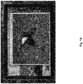
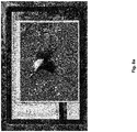
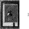
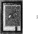
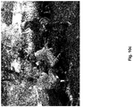
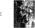
- Figures 1a and 1b show a first and second sample image representing a common reflection problem.
- Light-generating objects in the area facing the display device causes reflection on the display device that appear as whitish highlights on the display device.
- FIG. 2 therein illustrated is a flowchart of the operational steps of an example method 100 for compensating for specular reflection on a display device.
- one or more images of a scene facing the display device is captured.
- the display device is to be used to display one or more target images.
- the scene facing the display device corresponds to the environment in front of the display device.
- any object in the scene that emits light that causes specular reflection on the display device is referred herein generally as a "light-generating object". It will be understood that the light-generating object may directly emit light that causes specular reflections, or the light-generating object may be reflecting light from an external source, the reflected light further causing specular reflections on the display device.
- the one or more images may be captured sequentially, such as in a video. Accordingly, the scene being captured in the images may change over the sequence, such as due to a change in orientation of the image capture device or changes to objects in the scene.
- the one or more images of the scene are captured by an image capture device.
- the image capture device may be positioned to be offset by a known distance and orientation from the display device.
- the image capture device is located in proximity of the display device and is facing the same direction as the display device.
- the image capture device may be an external camera positioned in proximity of the display device.
- the image capture device may be an embedded camera, such as the front facing camera of a mobile device (smartphone, tablet, laptop with webcam, video game console, etc.).
- the image capture device may be a combination of capture devices, such as a combination of a camera and an ambient light sensor.
- the camera and the ambient light sensor are located in proximity of one another such that a scene captured by the camera substantially corresponds to the scene captured by the ambient light sensor. It will be appreciated that various mobile devices are now offered with both a camera and an ambient light sensor.
- the image capture devices may have two or more cameras, which may be operated to capture the scene while providing depth information of objects within the scene (ex: stereoscopic cameras).
- An additional device operable to determine depth such as a time-of-flight sensor, can also be used.
- the images captured of the scene may be down-sampled to a lower resolution, which may improve processing speed. It will be appreciated that steps described herein that operate on captured images of the scene facing the display can refer to the down-sampled captured images.
- the scene facing the display device represented in the images captured by the image capture device is defined by the field of view of the capture device.
- one or more reflection-inducing zones located within the one or more captured images are identified.
- the reflection-inducing zones correspond to light-generating objects in the scene that can cause specular reflections on the display device.
- the reflection-inducing zones are areas of the capture images that have a sufficiently high luminance value that indicates bright light-generating objects in the scene.
- the specular reflection effect on the display device caused by the light-generating objects, and as represented by the reflection-inducing zones in the captured images, are determined.
- the specular reflection effect represents an estimation of how a viewer viewing the display device would perceive specular reflections caused by light-generating objects in the scene facing the display device.
- a target image that is to be displayed on the display device is adjusted based on the reflection effect.
- the target image may be adjusted to reduce or mitigate the reflections perceived by the viewer.
- the adjustment may include digitally processing the target image.
- FIG. 3 therein illustrated is a flowchart of the operational steps of an example method for identifying one or more reflection-inducing zones located within the one or more captured images.
- the method may correspond to substeps of step 116.
- an area of the one or more captured images that is not a reflection-inducing zone is identified. This zone corresponds to a part of the scene facing the display device that will not cause significant specular reflections to be perceived by the viewer.
- the face of the viewer is captured within the images of the scene facing the display device and zone of the images corresponding to a portion of the face of the viewer is used as a reference area to set a threshold for identifying reflection-inducing zones of the captured images.
- a threshold for identifying reflection-inducing zones of the captured images.
- an area of the face corresponding to the bridge of the viewer's nose may be used.
- the area may also include parts of the forehead and portions of each eye of the user.
- a threshold for determining reflection-inducing zones is set.
- the threshold may be set as a luminance value that is a multiple (ex: 100 times) of the average of the luminance values of the pixels forming the reference area within the captured images.
- the threshold may be set as a factor of a maximum image value (ex: high luminance in the reference area such that the threshold exceeds maximum luminance pixel values).
- the areas of the captured image that have luminance values that exceed the threshold are determined to be reflection-inducing zones.
- a smoothing or dilating may be applied to remove reflection-inducing zones below a certain size.
- the distances of each light-generating object represented by the reflection-inducing zones from the display device are determined. That is, for each reflection-inducing zone identified from step 224, the distance of the real-life light-generating object represented by that reflection-inducing zone is determined.
- the distances of each light-generating object may be determined from known properties of the scene facing the display device. This may be the case where the scene is fixed relative to the display device.
- the location of each light-generating object in the scene, including their distance from the display device, can be predefined and the identified reflection-inducing zones are matched to its corresponding light-generating object.
- a display device such as computer monitor or a TV may be in a fixed position in a space, such as within a room, and light-generating objects found within the space (ex: walls, windows, light fixtures, lamps) are predefined.
- the display device in a fixed position may be an electronic billboard or other display device positioned in a public space.
- a display device may be in a fixed position inside the interior cabin of an automobile and light-generating objects of the cabin (ex: windows of the vehicle, lights inside the cabin) are predefined. It will be appreciated that although the automobile is movable, the display device remains in a fixed position relative to the interior of the cabin.
- properties of the scene such as location and brightness of light-generating objects, may be known ahead of time. For example, such properties may be pre-measured and pre-stored.
- the distance of light-generating objects within the scene from the display device is determined from sensed motion of the display device and the movement of reflection-inducing zones within images captured of the scene as the display device is moved.
- the distance of the light-generating objects can be calculated based on parallax effect.
- the determining of distances of light generating objects within the scene may take into account the offset of the image capture device from the display device. Additionally or alternatively, the determining of the distances of the light generating objects within the scene may take into account the position of the viewer, such as the viewer's eyes.
- FIG. 4 therein illustrated is a flowchart showing the operational steps of an example method 232 for determining distance of light-generating objects in the scene from the display device.
- the motion of the image capture device is sensed.
- the motion may be sensed by a sensor external to the image capture device but that is representative of the motion of the image capture device.
- the display device is a mobile device (ex: smartphone, tablet, laptop, portable video console)
- the motion may be sensed with a motion sensor of the mobile device, such as a gyroscope.
- a motion sensor of the mobile device such as a gyroscope.
- the movement of reflection inducing zones within the scene is determined from the plurality of images of the scene captured during movement of the image capture device.
- the sensed motion of the image capture device is correlated within the determined movement of reflection inducing zones to determine the distance of light-generating objects represented by the reflection inducing zones from the display device.
- lateral movement of the image capture device is sensed. Furthermore, edges of the reflection-inducing zones that are approximately perpendicular to the direction of motion are identified. The movement of the edges within the scene represented by the plurality of captured images are identified. Movement of edges that are counter to the sensed motion is ignored. Edges with least amount of movement within the captured scene are determined to be located at a higher distance (ex: infinity) from the display device. Edges with greater motion are determined to be closer to the display device.
- Occlusion objects within the scene are also detected.
- Occlusion objects correspond to objects located between a light-generating object and the display device and acts to block some of the reflection exhibited on the display device.
- FIG. 5 therein illustrated is a flowchart of the operational steps of an example method 124 for determining the reflection effect on the display device caused by the reflection-inducing zones identified at step 116.
- the position of a viewer viewing the display device is determined.
- Object recognition of the images captured of the scene facing the display device can be performed to recognize the viewer.
- the eyes of the viewer are located.
- the position of the viewer can be tracked over time.
- the reflection-inducing zones identified at 116 and distance of each light-generating objects represented by the reflection-inducing zones are received.
- reflection zones are determined based on the position of the viewer and information pertaining to the reflection-inducing zones and distances of the corresponding light-generating objects from display device.
- the reflection zones that are determined represent the reflection exhibited on the display device as perceived by the user caused by light-generating objects in the scene. It will be appreciated that the reflection zones may cover only a portion of the area of the display device. For example, some areas of the display device do not correspond to a reflection-inducing zone and therefore are determined to not exhibit reflection.
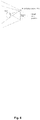
- FIG. 6 therein illustrated is a schematic diagram showing the relative positions of a viewer, the display device and an image capture device.
- reflections on the display device perceived by the viewer correspond to the viewer's view of light-generating objects in the scene as seen from the virtual view position, which corresponds to the position of the viewer's eyes mirrored over the display device.
- the image capture device that captures images of the scene is offset from the virtual view position. Accordingly, an extrapolation is applied to determine how light-generating objects represented as reflection-inducing zones in the images captured would be seen from the virtual view position.
- the reflection zones may be represented as a veiling glare in the form of a 2-D array, wherein values in the array define the luminance value of the reflection zones as perceived by the viewer on the display device.
- FIG. 7 therein illustrated is a flowchart of the operational steps of an example method 132 for adjusting the target image to be displayed based on the reflection effect.
- the reflection zones determined at step 424 are received.
- the veiling glare defining luminance values of the reflection zone is also received.
- the luminance values of the reflection zone are compared with luminance values of the target image to determine the adjustment to be applied to the target image. For example, the luminance value of the reflection zone at a given area on the display device is compared with luminance value at a corresponding area (when displayed on the display device) of the target image.
- the comparison of luminance values may be carried out on a pixel-by-pixel basis. Upsampling of the veiling glare may applied.
- the luminance values of the pixels within the one or more subareas areas are decreased.
- the luminance values of the pixels of the target image in the subareas are less than luminance values in corresponding subareas of the reflection zone.
- this has the effect of reducing luminance values in the target image in areas where the target image already has high luminance values and boosting the luminance values in the target image in areas where the target images does not have luminance values.
- Areas of the target image that correspond to areas of the display device that does not exhibit reflection are not adjusted.
- the target image is adjusted according to the adjustment calculated at step 516.
- the adjusted target image is displayed on the display device.
- the basic concept is to take continuous video, ambient light and motion sensor data from a mobile device, and use it to deduce in real-time the current reflections seen by the user on his or her screen.
- the head position is simultaneously tracked in order to reproject the bright regions as seen by the front-facing camera.
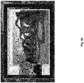
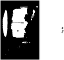
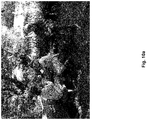
- the main challenge with veil subtraction lies in the accurate prediction of the reflection image as seen from the viewer's perspective. If the reflection image is in the wrong place, the results may be deteriorated due to subtracting the wrong veil, as shown in Figures 8a and 8b .
- Veil estimation requires (a) knowing where the viewer's eyes are located and (b) knowing the brightness and position of significant reflection sources are, both relative to the display.
- the device being used is equipped with a front-facing camera, an ambient light sensor, and motion sensors to provide when and how the display is moving.
- a front-facing camera to provide when and how the display is moving.
- An aim is to keep the computational complexity low as well so as not to tax the CPU, GPU, or battery too heavily.
- Reprojection is also simplified, as a small number of discrete positions are moved along a set of 3-D contours and in-filling to estimate new highlights. This is designed as a lightweight process.
- a threshold is set empirically based on the captured image pixel value at the bridge of the user's nose. Since it is expected this will be proportional to the viewer's eye adaptation and already in camera brightness units, whatever the exposure happens to be, this serves as a convenient way to set the threshold.
- a square area equal to the inter-ocular spacing is averaged, which covers most of the nose, some of the forehead, and roughly half of each eye.
- the highlight threshold is set to a multiple (ex: 100 times) of this average, or a factor (ex: 0.92) of the maximum image value in a [0,1] range, whichever is smaller.
- Down-sampled capture image pixels that are above threshold using a 2-D bitmap are marked. This bitmap is subsequently eroded and dilated to remove isolated highlights that would be too small to remedy.
- the front camera geometry and determined head position is used to extrapolate the view behind the screen that corresponds to the reflected image from the user's perspective.
- distance estimates for all the scene pixels is needed, which is obtained from a call-back function. In the demo for a car, this function will use the mock-up car's window geometry.
- the virtual view that would not require any reprojection corresponds to an impossible position behind the display.
- Reprojecting highlights captured by the front camera depends on the distances to objects in the scene.
- the distance to the viewer's head outline can be estimated from eye-tracking data, and other distances based on a fixed automobile demo geometry.
- the diagram shown also simplifies the problem by showing only one eye. Since it is assumed that the viewer has two eyes, the reprojection is performed twice and overlay the results. A 50% factor may be used for each highlight after normalization based on the ambient sensor value.
- pixel areas are opened up, using a quad-filling method. It is understood that there are portions of the reprojected view obstructed by the viewer's head, where the highlights will be uncertain. These will be filled with highlight or non-highlight regions, depending on the boundaries.
- the final highlight image is then converted to absolute luminance as reflected in the display using a measured screen reflectance value.
- the overall strategy is to subtract the veil due to highlights where target image values permit, and raise other values as necessary to subtract the veil in target regions that would otherwise be too dark for subtraction. This fits the goal of maintaining local contrast despite highlights, at the expense of manipulating brightness in some highlight regions.
- the overall effect is an interesting one, which sits visually between emissive and reflective displays. In brighter regions of the target image, where veil subtraction just works, the veil largely disappears and colors are restored. In darker regions, the image highlight is like dappled light on a reflection print, bringing up local brightness while preserving contrast and color appearance. This ends up being much less objectionable than other manipulations tested.
- Target image values are converted to single-channel floating-point in a [0,1] range.
- the L low and L high values are calculated within small regions of the target image used to set the local multiplier m.
- This down-sampled multiplier image as well as the veil image are smoothed (blurred) by a certain amount to avoid the appearance of artificial boundaries.
- the headroom constant k may be used to provide additional range on displays that can boost small regions to bright values, but have difficulty maintaining high total output, such as OLED devices. Settings above 1.0 will slightly dim the display everywhere that added brightness is not needed to compensate for highlights.
- the automotive application is a constrained subproblem that avoids the need to estimate the distances to highlight boundaries in the scene, since the rough geometry of the vehicle is known.
- the viewer's head position still needs to be tracked based on front-camera data.
- Android comes with built-in calls that perform this task.
- the viewer's eye position together with the camera field of view and position with respect to the display area are used to reproject bright region locations to where they are expected to appear in the reflected screen.
- This step is performed on a pixel-by-pixel basis in over-threshold regions of the captured image, but at a reduced resolution to maintain responsiveness. In this situation, shifts in the viewer's head position and changes in the scene behind the viewer are responded to. Some delay (ex: on the order of fraction of seconds) is acceptable.
- the example implementation seeks to simulate an in-dash display roughly positioned in front of the driver.
- test accuracy of head-tracking combined with reflection prediction by tracing expected (reflected) window outlines in tablet display.
- thresholding technique identify bright region boundaries and use perpendicular in-plane motion to estimate distances and connect contours as needed where distances are unreliable. Check against measurements.
- the current demo implementation consists of two C++ classes that run on a Samsung tablet device, and a Java interface with GPU code to interface with Android and the graphics hardware.
- a Java interface with GPU code to interface with Android and the graphics hardware.
- the first C++ class is GetHighlights, and its purpose is to determine the position and relative intensity of reflected highlights visible to the viewer. All of the above information is needed except for the target display image (f), which is applied in another class, HideHighlights.
- the GetHighlights class performs the following operations on the input:
- step (5) is specifically designed to compensate for this lack of calibration, substituting the absolute value from the ambient sensor and inferring that most of the measured light is represented somewhere in the image, even if it shows only as white. By scaling the highlights by the ambient sensor reading, the recorded highlights are obtained back into roughly the correct range.
- the only assumption is that the exposure is bright enough to track the user's eye positions and dim enough that everything else is not completely blown out. In cases where there is nothing significantly above the brightness of the viewer's face, no highlights will be returned and the loop can be paused until the ambient sensor detects a change in the lighting.
- the result produced by the GetHighlights class is a low-resolution image matching the display's aspect ratio with the highlights the viewer is expected to see reflected at the moment the front image was captured.
- This estimated highlight image then gets passed along with the target display image (f) to the HideHighlights class to perform the following steps:
- step (6) how pixel values translate to absolute luminance on the display needs to be known. This should be determined by the brightness setting available in Android, but there seems to be a complex, dynamic relation between this setting and the actual pixel luminances on the OLED display.
- the final operation (7) is the only one performed at full display resolution, but can be sped up easily enough by employing the GPU.
Landscapes
- Engineering & Computer Science (AREA)
- Physics & Mathematics (AREA)
- General Physics & Mathematics (AREA)
- Theoretical Computer Science (AREA)
- Computer Vision & Pattern Recognition (AREA)
- Computer Hardware Design (AREA)
- Computer Graphics (AREA)
- Controls And Circuits For Display Device (AREA)
Claims (15)
- Procédé de compensation de réflexion sur un dispositif d'affichage (604), le procédé comprenant :la capture (108), par un dispositif de capture d'images (602), d'une ou de plusieurs images d'une scène faisant face au dispositif d'affichage ;l'identification (116), à partir des images capturées, d'une ou de plusieurs zones induisant des réflexions situées dans la scène faisant face au dispositif d'affichage ;la détermination (124) d'un effet de réflexion spéculaire sur le dispositif d'affichage dû aux zones induisant des réflexions ; etle réglage (132) d'une image cible à afficher sur le dispositif d'affichage sur la base de l'effet de réflexion spéculaire déterminé ; etdans lequel la ou les zones induisant des réflexions sont déterminées sur la base de valeurs de luminance de pixels dans la ou les images capturées ;la ou les zones induisant des réflexions correspondent à des zones dans la ou les images capturées ayant une valeur de luminance supérieure à un seuil prédéterminé ;caractérisé en ce que la capture de l'image ou des images de la scène faisant face au dispositif d'affichage comprend la capture du visage d'un observateur situé dans la scène ; etle seuil prédéterminé est déterminé sur la base d'une valeur de luminance d'une zone dans la ou les images capturées correspondant à une partie du visage de l'observateur.
- Procédé selon la revendication 1, dans lequel le réglage de l'image cible comprend le réglage de valeurs de luminance d'une pluralité de pixels d'image dans une ou plusieurs régions de l'image cible.
- Procédé selon la revendication 1, dans lequel les régions de l'image cible correspondent à des zones induisant des réflexions identifiées à partir des images capturées.
- Procédé selon l'une quelconque des revendications 1 à 3, comprenant en outre la détermination à partir des images capturées d'une position de l'observateur regardant le dispositif d'affichage ; etdans lequel l'effet de réflexion sur le dispositif d'affichage dû aux zones induisant des réflexions est déterminé sur la base de la position de l'observateur et de la distance de chacune des zones induisant des réflexions par rapport au dispositif d'affichage ;dans lequel la détermination de la position de l'observateur comprend de préférence la détermination d'au moins un œil de l'observateur et dans lequel l'effet de réflexion est déterminé sur la base de la position des yeux.
- Procédé selon l'une quelconque des revendications 1 à 4, comprenant en outre :la réception de propriétés prédéfinies d'un ou de plusieurs objets produisant de la lumière situés dans la scène ;la mise en correspondance d'une ou de plusieurs zones induisant des réflexions avec un ou plusieurs objets produisant de la lumière correspondants ;la détermination de l'effet de réflexion spéculaire sur le dispositif d'affichage dû aux zones induisant des réflexions et aux propriétés prédéfinies des objets produisant de la lumière correspondants ; etle réglage de l'image cible à afficher sur le dispositif d'affichage sur la base de l'effet de réflexion spéculaire déterminé.
- Procédé selon la revendication 5,
dans lequel les propriétés prédéfinies de l'objet ou des objets produisant de la lumière situés dans la scène comprennent une ou plusieurs propriétés parmi l'emplacement, les valeurs de luminance prédéfinies et la taille de chacun des objets produisant de la lumière. - Procédé selon la revendication 6, comprenant en outre la détermination d'une distance d'une ou de plusieurs zones induisant des réflexions par rapport au dispositif d'affichage sur la base des propriétés prédéfinies des objets produisant de la lumière.
- Procédé selon l'une quelconque des revendications 5 à 7 dans lequel les objets produisant de la lumière sont des objets d'un habitacle d'une automobile et où le dispositif d'affichage est situé à une position fixe à l'intérieur de l'habitacle de l'automobile.
- Procédé selon l'une quelconque des revendications 5 à 8, comprenant en outre l'identification d'éléments d'occlusion situés dans la scène.
- Procédé selon l'une quelconque des revendications 1 à 9, dans lequel l'effet de réflexion définit un emplacement et des valeurs de luminance de pixels d'image d'une ou de plusieurs zones de réflexion présentées sur le dispositif d'affichage en raison des zones induisant des réflexions situées dans la scène faisant face au dispositif d'affichage ; et
dans lequel le réglage de l'image cible comprend le réglage de valeurs de luminance dans l'image cible conformément à l'effet de réflexion déterminé. - Procédé selon la revendication 10, dans lequel le réglage de valeurs de luminance comprend pour une zone de l'image cible correspondant à une zone de réflexion :pour une ou plusieurs sous-zones de la zone où des valeurs de luminance des pixels de l'image cible sont supérieures aux valeurs de luminance de l'effet de réflexion dans des sous-zones correspondantes de la zone de réflexion, la réduction des valeurs de luminance des pixels dans la ou les sous-zones ; etpour une ou plusieurs sous-zones de la zone où des valeurs de luminance des pixels de l'image cible dans les sous-zones sont inférieures aux valeurs de luminance de l'effet de réflexion dans des sous-zones correspondantes de la zone de réflexion, l'augmentation des valeurs de luminance des pixels dans la ou les sous-zones.
- Procédé selon la revendication 11, dans lequel les valeurs de pixel dans la zone de l'image cible correspondant à la zone donnée parmi la ou les zones de réflexion sont réglées conformément à :
 L'est la valeur de luminance réglée du pixel de l'image cible dans la zone,L est la valeur de luminance originale du pixel de l'image cible dans la zone,Vest la valeur de luminance de l'effet de réflexion du pixel correspondant dans la zone correspondante de la zone de réflexion,
 Vavg est la moyenne locale des valeurs de luminance de l'effet de réflexion du pixel correspondant dans la zone correspondante de la zone de réflexion,Llow est le minimum local des valeurs de luminance originales des pixels de l'image cible dans la zone,Lhigh est le maximum local des valeurs de luminance originales des pixels de l'image cible dans la zone, etk est une valeur de marge qui est ≥ 1,0.
 - Procédé selon l'une quelconque des revendications 1 à 11, dans lequel la ou les images de la scène faisant face au dispositif d'affichage sont capturées par une caméra parmi :une caméra orientée vers l'avant décalée selon une distance et une orientation connues par rapport au dispositif d'affichage ; et/ouune caméra orientée vers l'avant en association avec un capteur de lumière ambiante, la caméra orientée vers l'avant et le capteur de lumière ambiante étant positionnés à proximité du dispositif d'affichage.
- Procédé selon l'une quelconque des revendications 1 à 13, dans lequel le réglage de l'image cible est en outre basé sur une réflexion prédéfinie du dispositif d'affichage.
- Système mis en œuvre par ordinateur comprenant :un dispositif d'affichage (604) ;un dispositif de capture d'images (602) ;au moins un dispositif de stockage de données ; etau moins un processeur couplé de manière opérationnelle à l'au moins un dispositif de stockage, au dispositif d'affichage et au dispositif de capture d'images,l'au moins un processeur étant conçu pour exécuter le procédé selon l'une quelconque des revendications 1 à 14.
Applications Claiming Priority (2)
| Application Number | Priority Date | Filing Date | Title |
|---|---|---|---|
| US201662436667P | 2016-12-20 | 2016-12-20 | |
| PCT/CA2017/051526 WO2018112609A1 (fr) | 2016-12-20 | 2017-12-18 | Système et procédé de compensation de réflexion sur un dispositif d'affichage |
Publications (4)
| Publication Number | Publication Date |
|---|---|
| EP3559900A1 EP3559900A1 (fr) | 2019-10-30 |
| EP3559900A4 EP3559900A4 (fr) | 2020-06-17 |
| EP3559900B1 true EP3559900B1 (fr) | 2021-08-18 |
| EP3559900B8 EP3559900B8 (fr) | 2021-09-22 |
Family
ID=62624571
Family Applications (1)
| Application Number | Title | Priority Date | Filing Date |
|---|---|---|---|
| EP17883609.4A Active EP3559900B8 (fr) | 2016-12-20 | 2017-12-18 | Système et procédé de compensation de réflexion sur un dispositif d'affichage |
Country Status (6)
| Country | Link |
|---|---|
| US (3) | US11250811B2 (fr) |
| EP (1) | EP3559900B8 (fr) |
| JP (1) | JP7181202B2 (fr) |
| CN (1) | CN110235171B (fr) |
| CA (1) | CA3047805A1 (fr) |
| WO (1) | WO2018112609A1 (fr) |
Cited By (1)
| Publication number | Priority date | Publication date | Assignee | Title |
|---|---|---|---|---|
| EP4315310A1 (fr) * | 2021-03-31 | 2024-02-07 | Continental Automotive Technologies GmbH | Système et procédé d'ajustement d'un niveau de luminance d'un dispositif d'affichage |
Families Citing this family (10)
| Publication number | Priority date | Publication date | Assignee | Title |
|---|---|---|---|---|
| JP7181202B2 (ja) | 2016-12-20 | 2022-11-30 | フォルシア イリステック インコーポレイテッド | ディスプレイ装置上の反射の補正のためのシステムおよび方法 |
| US11159737B2 (en) * | 2019-10-14 | 2021-10-26 | Google Llc | Exposure change control in low light environments |
| US12372409B2 (en) | 2020-01-10 | 2025-07-29 | Teledyne Flir Commercial Systems, Inc. | Radiometric thermal imaging improvements for navigation systems and methods |
| EP4053682B1 (fr) * | 2021-03-01 | 2025-07-02 | Nokia Technologies Oy | Écran de dispositif d'utilisateur |
| EP4067814B1 (fr) * | 2021-03-29 | 2025-02-12 | Teledyne FLIR Commercial Systems, Inc. | Améliorations d'imagerie thermique radiométrique pour systèmes et procédés de navigation |
| JP2023011241A (ja) * | 2021-07-12 | 2023-01-24 | 株式会社デンソー | 車両用表示制御装置、車両用表示方法、及び車両用表示プログラム |
| CN115457918A (zh) * | 2022-09-30 | 2022-12-09 | 联想(北京)有限公司 | 一种处理方法及装置 |
| CN116543724B (zh) * | 2023-04-28 | 2026-02-13 | 北京优酷科技有限公司 | 输出画面矫正方法、设备和存储介质 |
| CN119132258B (zh) * | 2024-11-11 | 2025-02-28 | 深圳市易快来科技股份有限公司 | 一种全反射屏幕显示的图像处理方法及系统 |
| CN120564653A (zh) * | 2025-06-26 | 2025-08-29 | 西安隆宝电子科技有限公司 | 一种液晶屏亮度调节方法、系统、产品和介质 |
Family Cites Families (19)
| Publication number | Priority date | Publication date | Assignee | Title |
|---|---|---|---|---|
| US5442484A (en) | 1992-01-06 | 1995-08-15 | Mitsubishi Denki Kabushiki Kaisha | Retro-focus type lens and projection-type display apparatus |
| US5854661A (en) | 1997-09-30 | 1998-12-29 | Lucent Technologies Inc. | System and method for subtracting reflection images from a display screen |
| US6411306B1 (en) | 1997-11-14 | 2002-06-25 | Eastman Kodak Company | Automatic luminance and contrast adustment for display device |
| US20040070565A1 (en) * | 2001-12-05 | 2004-04-15 | Nayar Shree K | Method and apparatus for displaying images |
| US7545397B2 (en) | 2004-10-25 | 2009-06-09 | Bose Corporation | Enhancing contrast |
| US7725022B2 (en) * | 2006-08-22 | 2010-05-25 | Qualcomm Incorporated | Dynamic automatic exposure compensation for image capture devices |
| JP2009031337A (ja) * | 2007-07-24 | 2009-02-12 | Funai Electric Co Ltd | 映像表示装置 |
| JP2009244700A (ja) * | 2008-03-31 | 2009-10-22 | Equos Research Co Ltd | 画像表示装置 |
| JP5540537B2 (ja) * | 2009-03-24 | 2014-07-02 | 株式会社オートネットワーク技術研究所 | 制御装置、制御方法及びコンピュータプログラム |
| US9380292B2 (en) * | 2009-07-31 | 2016-06-28 | 3Dmedia Corporation | Methods, systems, and computer-readable storage media for generating three-dimensional (3D) images of a scene |
| US20120229487A1 (en) | 2011-03-11 | 2012-09-13 | Nokia Corporation | Method and Apparatus for Reflection Compensation |
| US8559753B2 (en) | 2011-09-23 | 2013-10-15 | The Boeing Company | Reflection removal system |
| JP5443533B2 (ja) | 2012-03-22 | 2014-03-19 | 株式会社東芝 | 画像処理装置、画像表示装置及び画像処理方法 |
| CN104584113B (zh) * | 2012-08-15 | 2017-03-08 | 富士胶片株式会社 | 显示装置 |
| JP2015022525A (ja) * | 2013-07-19 | 2015-02-02 | 富士通株式会社 | 情報処理装置、被写体部位の検出方法、及びプログラム |
| KR20150039458A (ko) * | 2013-10-02 | 2015-04-10 | 삼성전자주식회사 | 디스플레이장치 및 그 제어방법 |
| JP6432159B2 (ja) * | 2014-05-22 | 2018-12-05 | 凸版印刷株式会社 | 情報表示装置、情報表示方法、および情報表示プログラム |
| US9645008B2 (en) * | 2014-08-25 | 2017-05-09 | Apple Inc. | Light sensor windows for electronic devices |
| JP7181202B2 (ja) | 2016-12-20 | 2022-11-30 | フォルシア イリステック インコーポレイテッド | ディスプレイ装置上の反射の補正のためのシステムおよび方法 |
-
2017
- 2017-12-18 JP JP2019533169A patent/JP7181202B2/ja active Active
- 2017-12-18 EP EP17883609.4A patent/EP3559900B8/fr active Active
- 2017-12-18 CA CA3047805A patent/CA3047805A1/fr active Pending
- 2017-12-18 CN CN201780079262.3A patent/CN110235171B/zh active Active
- 2017-12-18 WO PCT/CA2017/051526 patent/WO2018112609A1/fr not_active Ceased
- 2017-12-18 US US16/471,156 patent/US11250811B2/en active Active
-
2022
- 2022-02-14 US US17/671,492 patent/US11783796B2/en active Active
-
2023
- 2023-10-09 US US18/377,948 patent/US12243502B2/en active Active
Cited By (1)
| Publication number | Priority date | Publication date | Assignee | Title |
|---|---|---|---|---|
| EP4315310A1 (fr) * | 2021-03-31 | 2024-02-07 | Continental Automotive Technologies GmbH | Système et procédé d'ajustement d'un niveau de luminance d'un dispositif d'affichage |
Also Published As
| Publication number | Publication date |
|---|---|
| CN110235171B (zh) | 2023-12-29 |
| US20220208144A1 (en) | 2022-06-30 |
| EP3559900A1 (fr) | 2019-10-30 |
| EP3559900A4 (fr) | 2020-06-17 |
| EP3559900B8 (fr) | 2021-09-22 |
| US11250811B2 (en) | 2022-02-15 |
| JP2020504836A (ja) | 2020-02-13 |
| US12243502B2 (en) | 2025-03-04 |
| US20200258474A2 (en) | 2020-08-13 |
| US20200027423A1 (en) | 2020-01-23 |
| CA3047805A1 (fr) | 2018-06-28 |
| JP7181202B2 (ja) | 2022-11-30 |
| US20240119915A1 (en) | 2024-04-11 |
| WO2018112609A1 (fr) | 2018-06-28 |
| CN110235171A (zh) | 2019-09-13 |
| US11783796B2 (en) | 2023-10-10 |
Similar Documents
| Publication | Publication Date | Title |
|---|---|---|
| US12243502B2 (en) | System and method for compensation of reflection on a display device | |
| EP3827416B1 (fr) | Estimation d'éclairage pour réalité augmentée | |
| EP3602248B1 (fr) | Application sélective de traitement de reprojection sur des sous-régions de couche pour optimiser une puissance de re-projection tardive | |
| US10380802B2 (en) | Projecting augmentation images onto moving objects | |
| EP2458554B1 (fr) | Poursuite basée sur le mouvement | |
| US20210278678A1 (en) | Distributed Foveated Rendering Based on User Gaze | |
| US9652662B2 (en) | Image processing device and image processing method | |
| US11170578B1 (en) | Occlusion detection | |
| CN112805755B (zh) | 信息处理装置、信息处理方法和记录介质 | |
| EP3757655B1 (fr) | Procédé et système d'estimation de la position de la cornée en 3d | |
| US20190135197A1 (en) | Image generation device, image generation method, recording medium, and image display system | |
| US11544910B2 (en) | System and method for positioning image elements in augmented reality system | |
| EP3065107B1 (fr) | Estimation de mouvement cohérent pour une vidéo stéréoscopique | |
| US20250104580A1 (en) | Optical artifact mitigation and content display enhancement | |
| EP3811326A1 (fr) | Système et méthodologies de commande de contenu d'affichage tête haute (hud) | |
| CN115917598B (zh) | 用于确定视频中的移动对象的一致深度的模型 | |
| US20260038094A1 (en) | Fast low-light image visibility enhancement | |
| Ward et al. | 75‐3: Reducing Glare from Reflected Highlights in Mobile and Automotive Displays | |
| NZ756028B2 (en) | Selective application of reprojection processing on layer sub-regions for optimizing late stage reprojection power |
Legal Events
| Date | Code | Title | Description |
|---|---|---|---|
| STAA | Information on the status of an ep patent application or granted ep patent |
Free format text: STATUS: THE INTERNATIONAL PUBLICATION HAS BEEN MADE |
|
| PUAI | Public reference made under article 153(3) epc to a published international application that has entered the european phase |
Free format text: ORIGINAL CODE: 0009012 |
|
| STAA | Information on the status of an ep patent application or granted ep patent |
Free format text: STATUS: REQUEST FOR EXAMINATION WAS MADE |
|
| 17P | Request for examination filed |
Effective date: 20190702 |
|
| AK | Designated contracting states |
Kind code of ref document: A1 Designated state(s): AL AT BE BG CH CY CZ DE DK EE ES FI FR GB GR HR HU IE IS IT LI LT LU LV MC MK MT NL NO PL PT RO RS SE SI SK SM TR |
|
| AX | Request for extension of the european patent |
Extension state: BA ME |
|
| DAV | Request for validation of the european patent (deleted) | ||
| DAX | Request for extension of the european patent (deleted) | ||
| A4 | Supplementary search report drawn up and despatched |
Effective date: 20200520 |
|
| RIC1 | Information provided on ipc code assigned before grant |
Ipc: G06T 7/55 20170101ALI20200514BHEP Ipc: G06T 5/50 20060101ALI20200514BHEP Ipc: G06T 5/00 20060101AFI20200514BHEP Ipc: G09G 5/36 20060101ALI20200514BHEP |
|
| GRAP | Despatch of communication of intention to grant a patent |
Free format text: ORIGINAL CODE: EPIDOSNIGR1 |
|
| STAA | Information on the status of an ep patent application or granted ep patent |
Free format text: STATUS: GRANT OF PATENT IS INTENDED |
|
| INTG | Intention to grant announced |
Effective date: 20210318 |
|
| GRAS | Grant fee paid |
Free format text: ORIGINAL CODE: EPIDOSNIGR3 |
|
| GRAA | (expected) grant |
Free format text: ORIGINAL CODE: 0009210 |
|
| STAA | Information on the status of an ep patent application or granted ep patent |
Free format text: STATUS: THE PATENT HAS BEEN GRANTED |
|
| AK | Designated contracting states |
Kind code of ref document: B1 Designated state(s): AL AT BE BG CH CY CZ DE DK EE ES FI FR GB GR HR HU IE IS IT LI LT LU LV MC MK MT NL NO PL PT RO RS SE SI SK SM TR |
|
| REG | Reference to a national code |
Ref country code: GB Ref legal event code: FG4D |
|
| REG | Reference to a national code |
Ref country code: DE Ref legal event code: R081 Ref document number: 602017044499 Country of ref document: DE Owner name: FAURECIA LRYSTEC INC., MONTREAL, CA Free format text: FORMER OWNER: IRYSTEC SOFTWARE INC, MONTREAL, QUEBEC, CA |
|
| REG | Reference to a national code |
Ref country code: CH Ref legal event code: PK Free format text: BERICHTIGUNG B8 Ref country code: CH Ref legal event code: EP |
|
| REG | Reference to a national code |
Ref country code: DE Ref legal event code: R096 Ref document number: 602017044499 Country of ref document: DE |
|
| RAP2 | Party data changed (patent owner data changed or rights of a patent transferred) |
Owner name: FAURECIA IRYSTEC INC. |
|
| REG | Reference to a national code |
Ref country code: IE Ref legal event code: FG4D Ref country code: AT Ref legal event code: REF Ref document number: 1422313 Country of ref document: AT Kind code of ref document: T Effective date: 20210915 |
|
| REG | Reference to a national code |
Ref country code: SE Ref legal event code: TRGR |
|
| REG | Reference to a national code |
Ref country code: LT Ref legal event code: MG9D |
|
| REG | Reference to a national code |
Ref country code: NL Ref legal event code: MP Effective date: 20210818 |
|
| REG | Reference to a national code |
Ref country code: AT Ref legal event code: MK05 Ref document number: 1422313 Country of ref document: AT Kind code of ref document: T Effective date: 20210818 |
|
| PG25 | Lapsed in a contracting state [announced via postgrant information from national office to epo] |
Ref country code: HR Free format text: LAPSE BECAUSE OF FAILURE TO SUBMIT A TRANSLATION OF THE DESCRIPTION OR TO PAY THE FEE WITHIN THE PRESCRIBED TIME-LIMIT Effective date: 20210818 Ref country code: FI Free format text: LAPSE BECAUSE OF FAILURE TO SUBMIT A TRANSLATION OF THE DESCRIPTION OR TO PAY THE FEE WITHIN THE PRESCRIBED TIME-LIMIT Effective date: 20210818 Ref country code: ES Free format text: LAPSE BECAUSE OF FAILURE TO SUBMIT A TRANSLATION OF THE DESCRIPTION OR TO PAY THE FEE WITHIN THE PRESCRIBED TIME-LIMIT Effective date: 20210818 Ref country code: RS Free format text: LAPSE BECAUSE OF FAILURE TO SUBMIT A TRANSLATION OF THE DESCRIPTION OR TO PAY THE FEE WITHIN THE PRESCRIBED TIME-LIMIT Effective date: 20210818 Ref country code: LT Free format text: LAPSE BECAUSE OF FAILURE TO SUBMIT A TRANSLATION OF THE DESCRIPTION OR TO PAY THE FEE WITHIN THE PRESCRIBED TIME-LIMIT Effective date: 20210818 Ref country code: AT Free format text: LAPSE BECAUSE OF FAILURE TO SUBMIT A TRANSLATION OF THE DESCRIPTION OR TO PAY THE FEE WITHIN THE PRESCRIBED TIME-LIMIT Effective date: 20210818 Ref country code: BG Free format text: LAPSE BECAUSE OF FAILURE TO SUBMIT A TRANSLATION OF THE DESCRIPTION OR TO PAY THE FEE WITHIN THE PRESCRIBED TIME-LIMIT Effective date: 20211118 Ref country code: NO Free format text: LAPSE BECAUSE OF FAILURE TO SUBMIT A TRANSLATION OF THE DESCRIPTION OR TO PAY THE FEE WITHIN THE PRESCRIBED TIME-LIMIT Effective date: 20211118 Ref country code: PT Free format text: LAPSE BECAUSE OF FAILURE TO SUBMIT A TRANSLATION OF THE DESCRIPTION OR TO PAY THE FEE WITHIN THE PRESCRIBED TIME-LIMIT Effective date: 20211220 |
|
| PG25 | Lapsed in a contracting state [announced via postgrant information from national office to epo] |
Ref country code: PL Free format text: LAPSE BECAUSE OF FAILURE TO SUBMIT A TRANSLATION OF THE DESCRIPTION OR TO PAY THE FEE WITHIN THE PRESCRIBED TIME-LIMIT Effective date: 20210818 Ref country code: LV Free format text: LAPSE BECAUSE OF FAILURE TO SUBMIT A TRANSLATION OF THE DESCRIPTION OR TO PAY THE FEE WITHIN THE PRESCRIBED TIME-LIMIT Effective date: 20210818 Ref country code: GR Free format text: LAPSE BECAUSE OF FAILURE TO SUBMIT A TRANSLATION OF THE DESCRIPTION OR TO PAY THE FEE WITHIN THE PRESCRIBED TIME-LIMIT Effective date: 20211119 |
|
| PG25 | Lapsed in a contracting state [announced via postgrant information from national office to epo] |
Ref country code: NL Free format text: LAPSE BECAUSE OF FAILURE TO SUBMIT A TRANSLATION OF THE DESCRIPTION OR TO PAY THE FEE WITHIN THE PRESCRIBED TIME-LIMIT Effective date: 20210818 |
|
| PG25 | Lapsed in a contracting state [announced via postgrant information from national office to epo] |
Ref country code: DK Free format text: LAPSE BECAUSE OF FAILURE TO SUBMIT A TRANSLATION OF THE DESCRIPTION OR TO PAY THE FEE WITHIN THE PRESCRIBED TIME-LIMIT Effective date: 20210818 |
|
| REG | Reference to a national code |
Ref country code: DE Ref legal event code: R097 Ref document number: 602017044499 Country of ref document: DE |
|
| PG25 | Lapsed in a contracting state [announced via postgrant information from national office to epo] |
Ref country code: SM Free format text: LAPSE BECAUSE OF FAILURE TO SUBMIT A TRANSLATION OF THE DESCRIPTION OR TO PAY THE FEE WITHIN THE PRESCRIBED TIME-LIMIT Effective date: 20210818 Ref country code: SK Free format text: LAPSE BECAUSE OF FAILURE TO SUBMIT A TRANSLATION OF THE DESCRIPTION OR TO PAY THE FEE WITHIN THE PRESCRIBED TIME-LIMIT Effective date: 20210818 Ref country code: RO Free format text: LAPSE BECAUSE OF FAILURE TO SUBMIT A TRANSLATION OF THE DESCRIPTION OR TO PAY THE FEE WITHIN THE PRESCRIBED TIME-LIMIT Effective date: 20210818 Ref country code: EE Free format text: LAPSE BECAUSE OF FAILURE TO SUBMIT A TRANSLATION OF THE DESCRIPTION OR TO PAY THE FEE WITHIN THE PRESCRIBED TIME-LIMIT Effective date: 20210818 Ref country code: CZ Free format text: LAPSE BECAUSE OF FAILURE TO SUBMIT A TRANSLATION OF THE DESCRIPTION OR TO PAY THE FEE WITHIN THE PRESCRIBED TIME-LIMIT Effective date: 20210818 Ref country code: AL Free format text: LAPSE BECAUSE OF FAILURE TO SUBMIT A TRANSLATION OF THE DESCRIPTION OR TO PAY THE FEE WITHIN THE PRESCRIBED TIME-LIMIT Effective date: 20210818 |
|
| PLBE | No opposition filed within time limit |
Free format text: ORIGINAL CODE: 0009261 |
|
| STAA | Information on the status of an ep patent application or granted ep patent |
Free format text: STATUS: NO OPPOSITION FILED WITHIN TIME LIMIT |
|
| 26N | No opposition filed |
Effective date: 20220519 |
|
| PG25 | Lapsed in a contracting state [announced via postgrant information from national office to epo] |
Ref country code: MC Free format text: LAPSE BECAUSE OF FAILURE TO SUBMIT A TRANSLATION OF THE DESCRIPTION OR TO PAY THE FEE WITHIN THE PRESCRIBED TIME-LIMIT Effective date: 20210818 Ref country code: IT Free format text: LAPSE BECAUSE OF FAILURE TO SUBMIT A TRANSLATION OF THE DESCRIPTION OR TO PAY THE FEE WITHIN THE PRESCRIBED TIME-LIMIT Effective date: 20210818 |
|
| REG | Reference to a national code |
Ref country code: CH Ref legal event code: PL |
|
| PG25 | Lapsed in a contracting state [announced via postgrant information from national office to epo] |
Ref country code: SI Free format text: LAPSE BECAUSE OF FAILURE TO SUBMIT A TRANSLATION OF THE DESCRIPTION OR TO PAY THE FEE WITHIN THE PRESCRIBED TIME-LIMIT Effective date: 20210818 |
|
| REG | Reference to a national code |
Ref country code: BE Ref legal event code: MM Effective date: 20211231 |
|
| PG25 | Lapsed in a contracting state [announced via postgrant information from national office to epo] |
Ref country code: LU Free format text: LAPSE BECAUSE OF NON-PAYMENT OF DUE FEES Effective date: 20211218 Ref country code: IE Free format text: LAPSE BECAUSE OF NON-PAYMENT OF DUE FEES Effective date: 20211218 |
|
| PG25 | Lapsed in a contracting state [announced via postgrant information from national office to epo] |
Ref country code: BE Free format text: LAPSE BECAUSE OF NON-PAYMENT OF DUE FEES Effective date: 20211231 |
|
| PG25 | Lapsed in a contracting state [announced via postgrant information from national office to epo] |
Ref country code: LI Free format text: LAPSE BECAUSE OF NON-PAYMENT OF DUE FEES Effective date: 20211231 Ref country code: CH Free format text: LAPSE BECAUSE OF NON-PAYMENT OF DUE FEES Effective date: 20211231 |
|
| PG25 | Lapsed in a contracting state [announced via postgrant information from national office to epo] |
Ref country code: CY Free format text: LAPSE BECAUSE OF FAILURE TO SUBMIT A TRANSLATION OF THE DESCRIPTION OR TO PAY THE FEE WITHIN THE PRESCRIBED TIME-LIMIT Effective date: 20210818 |
|
| PG25 | Lapsed in a contracting state [announced via postgrant information from national office to epo] |
Ref country code: HU Free format text: LAPSE BECAUSE OF FAILURE TO SUBMIT A TRANSLATION OF THE DESCRIPTION OR TO PAY THE FEE WITHIN THE PRESCRIBED TIME-LIMIT; INVALID AB INITIO Effective date: 20171218 |
|
| PG25 | Lapsed in a contracting state [announced via postgrant information from national office to epo] |
Ref country code: MK Free format text: LAPSE BECAUSE OF FAILURE TO SUBMIT A TRANSLATION OF THE DESCRIPTION OR TO PAY THE FEE WITHIN THE PRESCRIBED TIME-LIMIT Effective date: 20210818 |
|
| PG25 | Lapsed in a contracting state [announced via postgrant information from national office to epo] |
Ref country code: TR Free format text: LAPSE BECAUSE OF FAILURE TO SUBMIT A TRANSLATION OF THE DESCRIPTION OR TO PAY THE FEE WITHIN THE PRESCRIBED TIME-LIMIT Effective date: 20210818 |
|
| PG25 | Lapsed in a contracting state [announced via postgrant information from national office to epo] |
Ref country code: MT Free format text: LAPSE BECAUSE OF FAILURE TO SUBMIT A TRANSLATION OF THE DESCRIPTION OR TO PAY THE FEE WITHIN THE PRESCRIBED TIME-LIMIT Effective date: 20210818 |
|
| PGFP | Annual fee paid to national office [announced via postgrant information from national office to epo] |
Ref country code: DE Payment date: 20251126 Year of fee payment: 9 |
|
| PGFP | Annual fee paid to national office [announced via postgrant information from national office to epo] |
Ref country code: GB Payment date: 20251120 Year of fee payment: 9 |
|
| PGFP | Annual fee paid to national office [announced via postgrant information from national office to epo] |
Ref country code: FR Payment date: 20251120 Year of fee payment: 9 |
|
| PGFP | Annual fee paid to national office [announced via postgrant information from national office to epo] |
Ref country code: SE Payment date: 20251119 Year of fee payment: 9 |