EP3559053B1 - Compositions and processes for self-assembly of block copolymers - Google Patents
Compositions and processes for self-assembly of block copolymers Download PDFInfo
- Publication number
- EP3559053B1 EP3559053B1 EP17835663.0A EP17835663A EP3559053B1 EP 3559053 B1 EP3559053 B1 EP 3559053B1 EP 17835663 A EP17835663 A EP 17835663A EP 3559053 B1 EP3559053 B1 EP 3559053B1
- Authority
- EP
- European Patent Office
- Prior art keywords
- layer
- substrate
- polymer
- grafted
- crosslinked
- Prior art date
- Legal status (The legal status is an assumption and is not a legal conclusion. Google has not performed a legal analysis and makes no representation as to the accuracy of the status listed.)
- Active
Links
- 229920001400 block copolymer Polymers 0.000 title claims description 121
- 238000000034 method Methods 0.000 title claims description 60
- 239000000203 mixture Substances 0.000 title claims description 42
- 230000008569 process Effects 0.000 title claims description 40
- 238000001338 self-assembly Methods 0.000 title description 16
- 229920000642 polymer Polymers 0.000 claims description 175
- 239000000758 substrate Substances 0.000 claims description 135
- 230000007935 neutral effect Effects 0.000 claims description 82
- 238000000576 coating method Methods 0.000 claims description 44
- 239000011248 coating agent Substances 0.000 claims description 43
- 239000001257 hydrogen Substances 0.000 claims description 38
- 229910052739 hydrogen Inorganic materials 0.000 claims description 38
- 239000002904 solvent Substances 0.000 claims description 33
- 238000002408 directed self-assembly Methods 0.000 claims description 31
- 229920002120 photoresistant polymer Polymers 0.000 claims description 29
- 125000000217 alkyl group Chemical group 0.000 claims description 27
- 238000005530 etching Methods 0.000 claims description 24
- 125000003545 alkoxy group Chemical group 0.000 claims description 20
- 238000010438 heat treatment Methods 0.000 claims description 20
- 239000000463 material Substances 0.000 claims description 19
- UFHFLCQGNIYNRP-UHFFFAOYSA-N Hydrogen Chemical compound [H][H] UFHFLCQGNIYNRP-UHFFFAOYSA-N 0.000 claims description 17
- 239000002243 precursor Substances 0.000 claims description 17
- 229920001577 copolymer Polymers 0.000 claims description 14
- 239000002253 acid Substances 0.000 claims description 12
- 150000004820 halides Chemical class 0.000 claims description 12
- 150000002431 hydrogen Chemical class 0.000 claims description 12
- 239000003960 organic solvent Substances 0.000 claims description 12
- 125000002947 alkylene group Chemical group 0.000 claims description 11
- 125000003709 fluoroalkyl group Chemical group 0.000 claims description 9
- 125000004665 trialkylsilyl group Chemical group 0.000 claims description 9
- 125000001931 aliphatic group Chemical group 0.000 claims description 7
- 238000000137 annealing Methods 0.000 claims description 6
- 125000004428 fluoroalkoxy group Chemical group 0.000 claims description 6
- 238000003384 imaging method Methods 0.000 claims description 5
- 125000005529 alkyleneoxy group Chemical group 0.000 claims description 3
- 239000010410 layer Substances 0.000 description 112
- 239000004793 Polystyrene Substances 0.000 description 39
- 230000015572 biosynthetic process Effects 0.000 description 35
- 229920002223 polystyrene Polymers 0.000 description 35
- OKKJLVBELUTLKV-UHFFFAOYSA-N Methanol Chemical compound OC OKKJLVBELUTLKV-UHFFFAOYSA-N 0.000 description 33
- 239000000243 solution Substances 0.000 description 32
- 239000010408 film Substances 0.000 description 30
- PPBRXRYQALVLMV-UHFFFAOYSA-N Styrene Chemical compound C=CC1=CC=CC=C1 PPBRXRYQALVLMV-UHFFFAOYSA-N 0.000 description 24
- 238000003786 synthesis reaction Methods 0.000 description 24
- -1 methoxy, ethoxy, propoxy, butoxy Chemical group 0.000 description 23
- WVDDGKGOMKODPV-UHFFFAOYSA-N Benzyl alcohol Chemical group OCC1=CC=CC=C1 WVDDGKGOMKODPV-UHFFFAOYSA-N 0.000 description 20
- VYPSYNLAJGMNEJ-UHFFFAOYSA-N Silicium dioxide Chemical compound O=[Si]=O VYPSYNLAJGMNEJ-UHFFFAOYSA-N 0.000 description 18
- NIXOWILDQLNWCW-UHFFFAOYSA-M Acrylate Chemical compound [O-]C(=O)C=C NIXOWILDQLNWCW-UHFFFAOYSA-M 0.000 description 17
- 235000012431 wafers Nutrition 0.000 description 17
- 239000000178 monomer Substances 0.000 description 16
- CSCPPACGZOOCGX-UHFFFAOYSA-N Acetone Chemical compound CC(C)=O CSCPPACGZOOCGX-UHFFFAOYSA-N 0.000 description 15
- 239000000126 substance Substances 0.000 description 14
- XLYOFNOQVPJJNP-UHFFFAOYSA-N water Substances O XLYOFNOQVPJJNP-UHFFFAOYSA-N 0.000 description 14
- 230000000052 comparative effect Effects 0.000 description 12
- 125000004435 hydrogen atom Chemical group [H]* 0.000 description 11
- 238000001459 lithography Methods 0.000 description 11
- WYURNTSHIVDZCO-UHFFFAOYSA-N tetrahydrofuran Substances C1CCOC1 WYURNTSHIVDZCO-UHFFFAOYSA-N 0.000 description 11
- WGOPGODQLGJZGL-UHFFFAOYSA-N lithium;butane Chemical compound [Li+].CC[CH-]C WGOPGODQLGJZGL-UHFFFAOYSA-N 0.000 description 10
- LLHKCFNBLRBOGN-UHFFFAOYSA-N propylene glycol methyl ether acetate Chemical compound COCC(C)OC(C)=O LLHKCFNBLRBOGN-UHFFFAOYSA-N 0.000 description 10
- 230000005855 radiation Effects 0.000 description 10
- 238000003756 stirring Methods 0.000 description 10
- YXFVVABEGXRONW-UHFFFAOYSA-N Toluene Chemical compound CC1=CC=CC=C1 YXFVVABEGXRONW-UHFFFAOYSA-N 0.000 description 9
- 238000012545 processing Methods 0.000 description 9
- 239000000377 silicon dioxide Substances 0.000 description 9
- 239000000654 additive Substances 0.000 description 8
- 238000006243 chemical reaction Methods 0.000 description 8
- 229910052710 silicon Inorganic materials 0.000 description 8
- WGTYBPLFGIVFAS-UHFFFAOYSA-M tetramethylammonium hydroxide Chemical compound [OH-].C[N+](C)(C)C WGTYBPLFGIVFAS-UHFFFAOYSA-M 0.000 description 8
- IJGRMHOSHXDMSA-UHFFFAOYSA-N Atomic nitrogen Chemical compound N#N IJGRMHOSHXDMSA-UHFFFAOYSA-N 0.000 description 7
- ZMXDDKWLCZADIW-UHFFFAOYSA-N N,N-Dimethylformamide Chemical compound CN(C)C=O ZMXDDKWLCZADIW-UHFFFAOYSA-N 0.000 description 7
- 239000003708 ampul Substances 0.000 description 7
- 229910052681 coesite Inorganic materials 0.000 description 7
- 229910052906 cristobalite Inorganic materials 0.000 description 7
- 229920003229 poly(methyl methacrylate) Polymers 0.000 description 7
- 239000004926 polymethyl methacrylate Substances 0.000 description 7
- 229910052682 stishovite Inorganic materials 0.000 description 7
- 238000012546 transfer Methods 0.000 description 7
- 229910052905 tridymite Inorganic materials 0.000 description 7
- XKRFYHLGVUSROY-UHFFFAOYSA-N Argon Chemical compound [Ar] XKRFYHLGVUSROY-UHFFFAOYSA-N 0.000 description 6
- YMWUJEATGCHHMB-UHFFFAOYSA-N Dichloromethane Chemical compound ClCCl YMWUJEATGCHHMB-UHFFFAOYSA-N 0.000 description 6
- RTZKZFJDLAIYFH-UHFFFAOYSA-N Diethyl ether Chemical compound CCOCC RTZKZFJDLAIYFH-UHFFFAOYSA-N 0.000 description 6
- IAZDPXIOMUYVGZ-UHFFFAOYSA-N Dimethylsulphoxide Chemical compound CS(C)=O IAZDPXIOMUYVGZ-UHFFFAOYSA-N 0.000 description 6
- LFQSCWFLJHTTHZ-UHFFFAOYSA-N Ethanol Chemical compound CCO LFQSCWFLJHTTHZ-UHFFFAOYSA-N 0.000 description 6
- VVQNEPGJFQJSBK-UHFFFAOYSA-N Methyl methacrylate Chemical compound COC(=O)C(C)=C VVQNEPGJFQJSBK-UHFFFAOYSA-N 0.000 description 6
- RDOXTESZEPMUJZ-UHFFFAOYSA-N anisole Chemical compound COC1=CC=CC=C1 RDOXTESZEPMUJZ-UHFFFAOYSA-N 0.000 description 6
- 125000003118 aryl group Chemical group 0.000 description 6
- 235000019445 benzyl alcohol Nutrition 0.000 description 6
- DKPFZGUDAPQIHT-UHFFFAOYSA-N butyl acetate Chemical compound CCCCOC(C)=O DKPFZGUDAPQIHT-UHFFFAOYSA-N 0.000 description 6
- LZCLXQDLBQLTDK-UHFFFAOYSA-N ethyl 2-hydroxypropanoate Chemical compound CCOC(=O)C(C)O LZCLXQDLBQLTDK-UHFFFAOYSA-N 0.000 description 6
- 239000011521 glass Substances 0.000 description 6
- 238000004519 manufacturing process Methods 0.000 description 6
- 125000001997 phenyl group Chemical group [H]C1=C([H])C([H])=C(*)C([H])=C1[H] 0.000 description 6
- 125000001424 substituent group Chemical group 0.000 description 6
- 239000010409 thin film Substances 0.000 description 6
- ZWEHNKRNPOVVGH-UHFFFAOYSA-N 2-Butanone Chemical compound CCC(C)=O ZWEHNKRNPOVVGH-UHFFFAOYSA-N 0.000 description 5
- IAYPIBMASNFSPL-UHFFFAOYSA-N Ethylene oxide Chemical compound C1CO1 IAYPIBMASNFSPL-UHFFFAOYSA-N 0.000 description 5
- XUIMIQQOPSSXEZ-UHFFFAOYSA-N Silicon Chemical compound [Si] XUIMIQQOPSSXEZ-UHFFFAOYSA-N 0.000 description 5
- 238000004132 cross linking Methods 0.000 description 5
- 229920000359 diblock copolymer Polymers 0.000 description 5
- 230000002349 favourable effect Effects 0.000 description 5
- 238000000671 immersion lithography Methods 0.000 description 5
- 239000003999 initiator Substances 0.000 description 5
- 125000002496 methyl group Chemical group [H]C([H])([H])* 0.000 description 5
- 239000011541 reaction mixture Substances 0.000 description 5
- 239000010703 silicon Substances 0.000 description 5
- YEJRWHAVMIAJKC-UHFFFAOYSA-N 4-Butyrolactone Chemical compound O=C1CCCO1 YEJRWHAVMIAJKC-UHFFFAOYSA-N 0.000 description 4
- CURLTUGMZLYLDI-UHFFFAOYSA-N Carbon dioxide Chemical compound O=C=O CURLTUGMZLYLDI-UHFFFAOYSA-N 0.000 description 4
- KFZMGEQAYNKOFK-UHFFFAOYSA-N Isopropanol Chemical compound CC(C)O KFZMGEQAYNKOFK-UHFFFAOYSA-N 0.000 description 4
- UFWIBTONFRDIAS-UHFFFAOYSA-N Naphthalene Chemical compound C1=CC=CC2=CC=CC=C21 UFWIBTONFRDIAS-UHFFFAOYSA-N 0.000 description 4
- MWPLVEDNUUSJAV-UHFFFAOYSA-N anthracene Chemical compound C1=CC=CC2=CC3=CC=CC=C3C=C21 MWPLVEDNUUSJAV-UHFFFAOYSA-N 0.000 description 4
- JHIVVAPYMSGYDF-UHFFFAOYSA-N cyclohexanone Chemical compound O=C1CCCCC1 JHIVVAPYMSGYDF-UHFFFAOYSA-N 0.000 description 4
- 230000007547 defect Effects 0.000 description 4
- SWXVUIWOUIDPGS-UHFFFAOYSA-N diacetone alcohol Chemical compound CC(=O)CC(C)(C)O SWXVUIWOUIDPGS-UHFFFAOYSA-N 0.000 description 4
- 239000000706 filtrate Substances 0.000 description 4
- 238000001914 filtration Methods 0.000 description 4
- CATSNJVOTSVZJV-UHFFFAOYSA-N heptan-2-one Chemical compound CCCCCC(C)=O CATSNJVOTSVZJV-UHFFFAOYSA-N 0.000 description 4
- 125000005647 linker group Chemical group 0.000 description 4
- JHJNPOSPVGRIAN-SFHVURJKSA-N n-[3-[(1s)-1-[[6-(3,4-dimethoxyphenyl)pyrazin-2-yl]amino]ethyl]phenyl]-5-methylpyridine-3-carboxamide Chemical compound C1=C(OC)C(OC)=CC=C1C1=CN=CC(N[C@@H](C)C=2C=C(NC(=O)C=3C=C(C)C=NC=3)C=CC=2)=N1 JHJNPOSPVGRIAN-SFHVURJKSA-N 0.000 description 4
- BVJSUAQZOZWCKN-UHFFFAOYSA-N p-hydroxybenzyl alcohol Chemical compound OCC1=CC=C(O)C=C1 BVJSUAQZOZWCKN-UHFFFAOYSA-N 0.000 description 4
- 238000001020 plasma etching Methods 0.000 description 4
- BBEAQIROQSPTKN-UHFFFAOYSA-N pyrene Chemical compound C1=CC=C2C=CC3=CC=CC4=CC=C1C2=C43 BBEAQIROQSPTKN-UHFFFAOYSA-N 0.000 description 4
- 230000009257 reactivity Effects 0.000 description 4
- QTBSBXVTEAMEQO-UHFFFAOYSA-N Acetic acid Chemical compound CC(O)=O QTBSBXVTEAMEQO-UHFFFAOYSA-N 0.000 description 3
- RYGMFSIKBFXOCR-UHFFFAOYSA-N Copper Chemical compound [Cu] RYGMFSIKBFXOCR-UHFFFAOYSA-N 0.000 description 3
- XEKOWRVHYACXOJ-UHFFFAOYSA-N Ethyl acetate Chemical compound CCOC(C)=O XEKOWRVHYACXOJ-UHFFFAOYSA-N 0.000 description 3
- HEMHJVSKTPXQMS-UHFFFAOYSA-M Sodium hydroxide Chemical compound [OH-].[Na+] HEMHJVSKTPXQMS-UHFFFAOYSA-M 0.000 description 3
- ZMANZCXQSJIPKH-UHFFFAOYSA-N Triethylamine Chemical compound CCN(CC)CC ZMANZCXQSJIPKH-UHFFFAOYSA-N 0.000 description 3
- 229910052782 aluminium Inorganic materials 0.000 description 3
- 229910052786 argon Inorganic materials 0.000 description 3
- QVGXLLKOCUKJST-UHFFFAOYSA-N atomic oxygen Chemical compound [O] QVGXLLKOCUKJST-UHFFFAOYSA-N 0.000 description 3
- 229910052802 copper Inorganic materials 0.000 description 3
- 239000010949 copper Substances 0.000 description 3
- 125000004122 cyclic group Chemical group 0.000 description 3
- 238000011161 development Methods 0.000 description 3
- 238000001035 drying Methods 0.000 description 3
- 238000000407 epitaxy Methods 0.000 description 3
- 229940116333 ethyl lactate Drugs 0.000 description 3
- 229910052731 fluorine Inorganic materials 0.000 description 3
- 229920000578 graft copolymer Polymers 0.000 description 3
- 230000003993 interaction Effects 0.000 description 3
- UZKWTJUDCOPSNM-UHFFFAOYSA-N methoxybenzene Substances CCCCOC=C UZKWTJUDCOPSNM-UHFFFAOYSA-N 0.000 description 3
- 238000004377 microelectronic Methods 0.000 description 3
- 229910052757 nitrogen Inorganic materials 0.000 description 3
- 239000003921 oil Substances 0.000 description 3
- 239000001301 oxygen Substances 0.000 description 3
- 229910052760 oxygen Inorganic materials 0.000 description 3
- 238000001556 precipitation Methods 0.000 description 3
- 235000012239 silicon dioxide Nutrition 0.000 description 3
- FVAUCKIRQBBSSJ-UHFFFAOYSA-M sodium iodide Chemical compound [Na+].[I-] FVAUCKIRQBBSSJ-UHFFFAOYSA-M 0.000 description 3
- 239000007787 solid Substances 0.000 description 3
- 238000009987 spinning Methods 0.000 description 3
- 239000004094 surface-active agent Substances 0.000 description 3
- FPGGTKZVZWFYPV-UHFFFAOYSA-M tetrabutylammonium fluoride Chemical compound [F-].CCCC[N+](CCCC)(CCCC)CCCC FPGGTKZVZWFYPV-UHFFFAOYSA-M 0.000 description 3
- 229910052719 titanium Inorganic materials 0.000 description 3
- 239000010936 titanium Substances 0.000 description 3
- 125000000008 (C1-C10) alkyl group Chemical group 0.000 description 2
- ARXJGSRGQADJSQ-UHFFFAOYSA-N 1-methoxypropan-2-ol Chemical compound COCC(C)O ARXJGSRGQADJSQ-UHFFFAOYSA-N 0.000 description 2
- XLLIQLLCWZCATF-UHFFFAOYSA-N 2-methoxyethyl acetate Chemical compound COCCOC(C)=O XLLIQLLCWZCATF-UHFFFAOYSA-N 0.000 description 2
- VFXXTYGQYWRHJP-UHFFFAOYSA-N 4,4'-azobis(4-cyanopentanoic acid) Chemical compound OC(=O)CCC(C)(C#N)N=NC(C)(CCC(O)=O)C#N VFXXTYGQYWRHJP-UHFFFAOYSA-N 0.000 description 2
- FUGYGGDSWSUORM-UHFFFAOYSA-N 4-hydroxystyrene Chemical compound OC1=CC=C(C=C)C=C1 FUGYGGDSWSUORM-UHFFFAOYSA-N 0.000 description 2
- YYROPELSRYBVMQ-UHFFFAOYSA-N 4-toluenesulfonyl chloride Chemical compound CC1=CC=C(S(Cl)(=O)=O)C=C1 YYROPELSRYBVMQ-UHFFFAOYSA-N 0.000 description 2
- KAKZBPTYRLMSJV-UHFFFAOYSA-N Butadiene Chemical compound C=CC=C KAKZBPTYRLMSJV-UHFFFAOYSA-N 0.000 description 2
- OKTJSMMVPCPJKN-UHFFFAOYSA-N Carbon Chemical compound [C] OKTJSMMVPCPJKN-UHFFFAOYSA-N 0.000 description 2
- VGGSQFUCUMXWEO-UHFFFAOYSA-N Ethene Chemical compound C=C VGGSQFUCUMXWEO-UHFFFAOYSA-N 0.000 description 2
- 239000005977 Ethylene Substances 0.000 description 2
- RRHGJUQNOFWUDK-UHFFFAOYSA-N Isoprene Chemical compound CC(=C)C=C RRHGJUQNOFWUDK-UHFFFAOYSA-N 0.000 description 2
- WMFOQBRAJBCJND-UHFFFAOYSA-M Lithium hydroxide Chemical compound [Li+].[OH-] WMFOQBRAJBCJND-UHFFFAOYSA-M 0.000 description 2
- FAPWRFPIFSIZLT-UHFFFAOYSA-M Sodium chloride Chemical compound [Na+].[Cl-] FAPWRFPIFSIZLT-UHFFFAOYSA-M 0.000 description 2
- YRKCREAYFQTBPV-UHFFFAOYSA-N acetylacetone Chemical compound CC(=O)CC(C)=O YRKCREAYFQTBPV-UHFFFAOYSA-N 0.000 description 2
- 150000001336 alkenes Chemical class 0.000 description 2
- XAGFODPZIPBFFR-UHFFFAOYSA-N aluminium Chemical compound [Al] XAGFODPZIPBFFR-UHFFFAOYSA-N 0.000 description 2
- 150000003863 ammonium salts Chemical class 0.000 description 2
- 229940072049 amyl acetate Drugs 0.000 description 2
- PGMYKACGEOXYJE-UHFFFAOYSA-N anhydrous amyl acetate Natural products CCCCCOC(C)=O PGMYKACGEOXYJE-UHFFFAOYSA-N 0.000 description 2
- 239000006117 anti-reflective coating Substances 0.000 description 2
- 238000013459 approach Methods 0.000 description 2
- 150000004945 aromatic hydrocarbons Chemical group 0.000 description 2
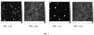
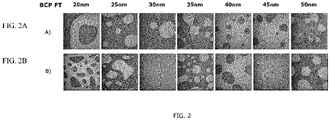
- 238000000089 atomic force micrograph Methods 0.000 description 2
- 230000004888 barrier function Effects 0.000 description 2
- 230000008901 benefit Effects 0.000 description 2
- DNFSNYQTQMVTOK-UHFFFAOYSA-N bis(4-tert-butylphenyl)iodanium Chemical compound C1=CC(C(C)(C)C)=CC=C1[I+]C1=CC=C(C(C)(C)C)C=C1 DNFSNYQTQMVTOK-UHFFFAOYSA-N 0.000 description 2
- 229910052799 carbon Inorganic materials 0.000 description 2
- 235000011089 carbon dioxide Nutrition 0.000 description 2
- 150000007942 carboxylates Chemical class 0.000 description 2
- 150000001875 compounds Chemical class 0.000 description 2
- 125000000113 cyclohexyl group Chemical group [H]C1([H])C([H])([H])C([H])([H])C([H])(*)C([H])([H])C1([H])[H] 0.000 description 2
- BGTOWKSIORTVQH-UHFFFAOYSA-N cyclopentanone Chemical compound O=C1CCCC1 BGTOWKSIORTVQH-UHFFFAOYSA-N 0.000 description 2
- 238000010511 deprotection reaction Methods 0.000 description 2
- 238000005516 engineering process Methods 0.000 description 2
- 125000001495 ethyl group Chemical group [H]C([H])([H])C([H])([H])* 0.000 description 2
- GVEPBJHOBDJJJI-UHFFFAOYSA-N fluoranthrene Natural products C1=CC(C2=CC=CC=C22)=C3C2=CC=CC3=C1 GVEPBJHOBDJJJI-UHFFFAOYSA-N 0.000 description 2
- 238000005227 gel permeation chromatography Methods 0.000 description 2
- 229910052732 germanium Inorganic materials 0.000 description 2
- MNWFXJYAOYHMED-UHFFFAOYSA-M heptanoate Chemical compound CCCCCCC([O-])=O MNWFXJYAOYHMED-UHFFFAOYSA-M 0.000 description 2
- 229920001519 homopolymer Polymers 0.000 description 2
- 150000002430 hydrocarbons Chemical group 0.000 description 2
- 125000001449 isopropyl group Chemical group [H]C([H])([H])C([H])(*)C([H])([H])[H] 0.000 description 2
- URMHJZVLKKDTOJ-UHFFFAOYSA-N lithium;(3-methyl-1-phenylpentyl)benzene Chemical compound [Li+].C=1C=CC=CC=1[C-](CC(C)CC)C1=CC=CC=C1 URMHJZVLKKDTOJ-UHFFFAOYSA-N 0.000 description 2
- 229920002521 macromolecule Polymers 0.000 description 2
- 229910052751 metal Inorganic materials 0.000 description 2
- 239000002184 metal Substances 0.000 description 2
- 229920006030 multiblock copolymer Polymers 0.000 description 2
- 239000012299 nitrogen atmosphere Substances 0.000 description 2
- JGTNAGYHADQMCM-UHFFFAOYSA-N perfluorobutanesulfonic acid Chemical compound OS(=O)(=O)C(F)(F)C(F)(F)C(F)(F)C(F)(F)F JGTNAGYHADQMCM-UHFFFAOYSA-N 0.000 description 2
- 239000013500 performance material Substances 0.000 description 2
- 239000011295 pitch Substances 0.000 description 2
- 230000001376 precipitating effect Effects 0.000 description 2
- 125000006239 protecting group Chemical group 0.000 description 2
- 238000000425 proton nuclear magnetic resonance spectrum Methods 0.000 description 2
- 238000000926 separation method Methods 0.000 description 2
- 125000001981 tert-butyldimethylsilyl group Chemical group [H]C([H])([H])[Si]([H])(C([H])([H])[H])[*]C(C([H])([H])[H])(C([H])([H])[H])C([H])([H])[H] 0.000 description 2
- YLQBMQCUIZJEEH-UHFFFAOYSA-N tetrahydrofuran Natural products C=1C=COC=1 YLQBMQCUIZJEEH-UHFFFAOYSA-N 0.000 description 2
- 229920000428 triblock copolymer Polymers 0.000 description 2
- 238000001039 wet etching Methods 0.000 description 2
- 238000009736 wetting Methods 0.000 description 2
- PAPBSGBWRJIAAV-UHFFFAOYSA-N ε-Caprolactone Chemical compound O=C1CCCCCO1 PAPBSGBWRJIAAV-UHFFFAOYSA-N 0.000 description 2
- DTGKSKDOIYIVQL-WEDXCCLWSA-N (+)-borneol Chemical group C1C[C@@]2(C)[C@@H](O)C[C@@H]1C2(C)C DTGKSKDOIYIVQL-WEDXCCLWSA-N 0.000 description 1
- UJMXMRBISVKKOI-UHFFFAOYSA-N (2-nitrophenyl)methyl trifluoromethanesulfonate Chemical compound [O-][N+](=O)C1=CC=CC=C1COS(=O)(=O)C(F)(F)F UJMXMRBISVKKOI-UHFFFAOYSA-N 0.000 description 1
- JAMNSIXSLVPNLC-UHFFFAOYSA-N (4-ethenylphenyl) acetate Chemical compound CC(=O)OC1=CC=C(C=C)C=C1 JAMNSIXSLVPNLC-UHFFFAOYSA-N 0.000 description 1
- DFMFSSOQMCTCGK-UHFFFAOYSA-N (4-nitrophenyl)methyl trifluoromethanesulfonate Chemical compound [O-][N+](=O)C1=CC=C(COS(=O)(=O)C(F)(F)F)C=C1 DFMFSSOQMCTCGK-UHFFFAOYSA-N 0.000 description 1
- 125000002030 1,2-phenylene group Chemical group [H]C1=C([H])C([*:1])=C([*:2])C([H])=C1[H] 0.000 description 1
- WNXJIVFYUVYPPR-UHFFFAOYSA-N 1,3-dioxolane Chemical compound C1COCO1 WNXJIVFYUVYPPR-UHFFFAOYSA-N 0.000 description 1
- 125000004955 1,4-cyclohexylene group Chemical group [H]C1([H])C([H])([H])C([H])([*:1])C([H])([H])C([H])([H])C1([H])[*:2] 0.000 description 1
- ZMYIIHDQURVDRB-UHFFFAOYSA-N 1-phenylethenylbenzene Chemical group C=1C=CC=CC=1C(=C)C1=CC=CC=C1 ZMYIIHDQURVDRB-UHFFFAOYSA-N 0.000 description 1
- BSZXAFXFTLXUFV-UHFFFAOYSA-N 1-phenylethylbenzene Chemical compound C=1C=CC=CC=1C(C)C1=CC=CC=C1 BSZXAFXFTLXUFV-UHFFFAOYSA-N 0.000 description 1
- FENFUOGYJVOCRY-UHFFFAOYSA-N 1-propoxypropan-2-ol Chemical compound CCCOCC(C)O FENFUOGYJVOCRY-UHFFFAOYSA-N 0.000 description 1
- 125000004206 2,2,2-trifluoroethyl group Chemical group [H]C([H])(*)C(F)(F)F 0.000 description 1
- FGQLGYBGTRHODR-UHFFFAOYSA-N 2,2-diethoxypropane Chemical compound CCOC(C)(C)OCC FGQLGYBGTRHODR-UHFFFAOYSA-N 0.000 description 1
- LTMRRSWNXVJMBA-UHFFFAOYSA-L 2,2-diethylpropanedioate Chemical compound CCC(CC)(C([O-])=O)C([O-])=O LTMRRSWNXVJMBA-UHFFFAOYSA-L 0.000 description 1
- IKMBXKGUMLSBOT-UHFFFAOYSA-N 2,3,4,5,6-pentafluorobenzenesulfonic acid Chemical class OS(=O)(=O)C1=C(F)C(F)=C(F)C(F)=C1F IKMBXKGUMLSBOT-UHFFFAOYSA-N 0.000 description 1
- SBASXUCJHJRPEV-UHFFFAOYSA-N 2-(2-methoxyethoxy)ethanol Chemical compound COCCOCCO SBASXUCJHJRPEV-UHFFFAOYSA-N 0.000 description 1
- XNWFRZJHXBZDAG-UHFFFAOYSA-N 2-METHOXYETHANOL Chemical compound COCCO XNWFRZJHXBZDAG-UHFFFAOYSA-N 0.000 description 1
- JTXMVXSTHSMVQF-UHFFFAOYSA-N 2-acetyloxyethyl acetate Chemical compound CC(=O)OCCOC(C)=O JTXMVXSTHSMVQF-UHFFFAOYSA-N 0.000 description 1
- ZCGZOPIPEZCKKQ-UHFFFAOYSA-N 2-ethoxy-2-methylpropanoic acid Chemical compound CCOC(C)(C)C(O)=O ZCGZOPIPEZCKKQ-UHFFFAOYSA-N 0.000 description 1
- ZNQVEEAIQZEUHB-UHFFFAOYSA-N 2-ethoxyethanol Chemical compound CCOCCO ZNQVEEAIQZEUHB-UHFFFAOYSA-N 0.000 description 1
- SVONRAPFKPVNKG-UHFFFAOYSA-N 2-ethoxyethyl acetate Chemical compound CCOCCOC(C)=O SVONRAPFKPVNKG-UHFFFAOYSA-N 0.000 description 1
- 125000000954 2-hydroxyethyl group Chemical group [H]C([*])([H])C([H])([H])O[H] 0.000 description 1
- IPDVQPDVQHNZQO-UHFFFAOYSA-N 2-hydroxyisoindole-1,3-dione;trifluoromethanesulfonic acid Chemical compound OS(=O)(=O)C(F)(F)F.C1=CC=C2C(=O)N(O)C(=O)C2=C1 IPDVQPDVQHNZQO-UHFFFAOYSA-N 0.000 description 1
- VATRWWPJWVCZTA-UHFFFAOYSA-N 3-oxo-n-[2-(trifluoromethyl)phenyl]butanamide Chemical compound CC(=O)CC(=O)NC1=CC=CC=C1C(F)(F)F VATRWWPJWVCZTA-UHFFFAOYSA-N 0.000 description 1
- JLBJTVDPSNHSKJ-UHFFFAOYSA-N 4-Methylstyrene Chemical compound CC1=CC=C(C=C)C=C1 JLBJTVDPSNHSKJ-UHFFFAOYSA-N 0.000 description 1
- LPEKGGXMPWTOCB-UHFFFAOYSA-N 8beta-(2,3-epoxy-2-methylbutyryloxy)-14-acetoxytithifolin Natural products COC(=O)C(C)O LPEKGGXMPWTOCB-UHFFFAOYSA-N 0.000 description 1
- 241000208140 Acer Species 0.000 description 1
- JBRZTFJDHDCESZ-UHFFFAOYSA-N AsGa Chemical compound [As]#[Ga] JBRZTFJDHDCESZ-UHFFFAOYSA-N 0.000 description 1
- YIEIATVZEVPKRS-BYYHNAKLSA-N C=1C=C(O)C=CC=1OC(=O)CCC(C)(C#N)/N=N/C(C#N)(C)CCC(=O)OC1=CC=C(O)C=C1 Chemical compound C=1C=C(O)C=CC=1OC(=O)CCC(C)(C#N)/N=N/C(C#N)(C)CCC(=O)OC1=CC=C(O)C=C1 YIEIATVZEVPKRS-BYYHNAKLSA-N 0.000 description 1
- GAWIXWVDTYZWAW-UHFFFAOYSA-N C[CH]O Chemical group C[CH]O GAWIXWVDTYZWAW-UHFFFAOYSA-N 0.000 description 1
- UGFAIRIUMAVXCW-UHFFFAOYSA-N Carbon monoxide Chemical compound [O+]#[C-] UGFAIRIUMAVXCW-UHFFFAOYSA-N 0.000 description 1
- 239000004970 Chain extender Substances 0.000 description 1
- 244000248349 Citrus limon Species 0.000 description 1
- 235000005979 Citrus limon Nutrition 0.000 description 1
- 239000004971 Cross linker Substances 0.000 description 1
- XDTMQSROBMDMFD-UHFFFAOYSA-N Cyclohexane Chemical compound C1CCCCC1 XDTMQSROBMDMFD-UHFFFAOYSA-N 0.000 description 1
- BUDQDWGNQVEFAC-UHFFFAOYSA-N Dihydropyran Chemical compound C1COC=CC1 BUDQDWGNQVEFAC-UHFFFAOYSA-N 0.000 description 1
- LCGLNKUTAGEVQW-UHFFFAOYSA-N Dimethyl ether Chemical compound COC LCGLNKUTAGEVQW-UHFFFAOYSA-N 0.000 description 1
- XXRCUYVCPSWGCC-UHFFFAOYSA-N Ethyl pyruvate Chemical compound CCOC(=O)C(C)=O XXRCUYVCPSWGCC-UHFFFAOYSA-N 0.000 description 1
- PXGOKWXKJXAPGV-UHFFFAOYSA-N Fluorine Chemical compound FF PXGOKWXKJXAPGV-UHFFFAOYSA-N 0.000 description 1
- XPDWGBQVDMORPB-UHFFFAOYSA-N Fluoroform Chemical compound FC(F)F XPDWGBQVDMORPB-UHFFFAOYSA-N 0.000 description 1
- 229910001218 Gallium arsenide Inorganic materials 0.000 description 1
- WHXSMMKQMYFTQS-UHFFFAOYSA-N Lithium Chemical compound [Li] WHXSMMKQMYFTQS-UHFFFAOYSA-N 0.000 description 1
- FXHOOIRPVKKKFG-UHFFFAOYSA-N N,N-Dimethylacetamide Chemical compound CN(C)C(C)=O FXHOOIRPVKKKFG-UHFFFAOYSA-N 0.000 description 1
- 239000004677 Nylon Substances 0.000 description 1
- 229920003171 Poly (ethylene oxide) Polymers 0.000 description 1
- 229910052581 Si3N4 Inorganic materials 0.000 description 1
- RTAQQCXQSZGOHL-UHFFFAOYSA-N Titanium Chemical compound [Ti] RTAQQCXQSZGOHL-UHFFFAOYSA-N 0.000 description 1
- 101100107923 Vitis labrusca AMAT gene Proteins 0.000 description 1
- AOWPVIWVMWUSBD-RNFRBKRXSA-N [(3r)-3-hydroxybutyl] (3r)-3-hydroxybutanoate Chemical compound C[C@@H](O)CCOC(=O)C[C@@H](C)O AOWPVIWVMWUSBD-RNFRBKRXSA-N 0.000 description 1
- JDHMKYGBWFPOHE-UHFFFAOYSA-N [3-(1-phenylethenyl)phenyl]methanol Chemical compound OCC1=CC=CC(C(=C)C=2C=CC=CC=2)=C1 JDHMKYGBWFPOHE-UHFFFAOYSA-N 0.000 description 1
- OGALXJIOJZXBBP-UHFFFAOYSA-N [4-(chloromethyl)phenyl]methanol Chemical compound OCC1=CC=C(CCl)C=C1 OGALXJIOJZXBBP-UHFFFAOYSA-N 0.000 description 1
- NVJPBZCLWGTJKD-UHFFFAOYSA-N [bis(4-tert-butylphenyl)-lambda3-iodanyl] trifluoromethanesulfonate Chemical compound CC(C)(C)c1ccc(cc1)[I](OS(=O)(=O)C(F)(F)F)c1ccc(cc1)C(C)(C)C NVJPBZCLWGTJKD-UHFFFAOYSA-N 0.000 description 1
- 238000010521 absorption reaction Methods 0.000 description 1
- DHKHKXVYLBGOIT-UHFFFAOYSA-N acetaldehyde Diethyl Acetal Natural products CCOC(C)OCC DHKHKXVYLBGOIT-UHFFFAOYSA-N 0.000 description 1
- 150000001241 acetals Chemical class 0.000 description 1
- 150000007513 acids Chemical class 0.000 description 1
- 230000000996 additive effect Effects 0.000 description 1
- 238000013019 agitation Methods 0.000 description 1
- 150000001298 alcohols Chemical class 0.000 description 1
- 239000012670 alkaline solution Substances 0.000 description 1
- IYABWNGZIDDRAK-UHFFFAOYSA-N allene Chemical group C=C=C IYABWNGZIDDRAK-UHFFFAOYSA-N 0.000 description 1
- XYLMUPLGERFSHI-UHFFFAOYSA-N alpha-Methylstyrene Chemical compound CC(=C)C1=CC=CC=C1 XYLMUPLGERFSHI-UHFFFAOYSA-N 0.000 description 1
- 230000004075 alteration Effects 0.000 description 1
- 150000001408 amides Chemical class 0.000 description 1
- 150000001450 anions Chemical class 0.000 description 1
- 238000003491 array Methods 0.000 description 1
- 125000000732 arylene group Chemical group 0.000 description 1
- FFBHFFJDDLITSX-UHFFFAOYSA-N benzyl N-[2-hydroxy-4-(3-oxomorpholin-4-yl)phenyl]carbamate Chemical compound OC1=C(NC(=O)OCC2=CC=CC=C2)C=CC(=C1)N1CCOCC1=O FFBHFFJDDLITSX-UHFFFAOYSA-N 0.000 description 1
- AGEZXYOZHKGVCM-UHFFFAOYSA-N benzyl bromide Chemical group BrCC1=CC=CC=C1 AGEZXYOZHKGVCM-UHFFFAOYSA-N 0.000 description 1
- 125000001797 benzyl group Chemical group [H]C1=C([H])C([H])=C(C([H])=C1[H])C([H])([H])* 0.000 description 1
- 125000002529 biphenylenyl group Chemical group C1(=CC=CC=2C3=CC=CC=C3C12)* 0.000 description 1
- 238000009835 boiling Methods 0.000 description 1
- 229910052794 bromium Inorganic materials 0.000 description 1
- 230000005587 bubbling Effects 0.000 description 1
- 229930188620 butyrolactone Natural products 0.000 description 1
- 125000004432 carbon atom Chemical group C* 0.000 description 1
- 239000001569 carbon dioxide Substances 0.000 description 1
- 229910002092 carbon dioxide Inorganic materials 0.000 description 1
- 229910002091 carbon monoxide Inorganic materials 0.000 description 1
- BVKZGUZCCUSVTD-UHFFFAOYSA-N carbonic acid Chemical class OC(O)=O BVKZGUZCCUSVTD-UHFFFAOYSA-N 0.000 description 1
- 238000005266 casting Methods 0.000 description 1
- 239000000919 ceramic Substances 0.000 description 1
- 230000008859 change Effects 0.000 description 1
- 239000003795 chemical substances by application Substances 0.000 description 1
- 125000004093 cyano group Chemical group *C#N 0.000 description 1
- 125000000753 cycloalkyl group Chemical group 0.000 description 1
- 125000002993 cycloalkylene group Chemical group 0.000 description 1
- 125000001511 cyclopentyl group Chemical group [H]C1([H])C([H])([H])C([H])([H])C([H])(*)C1([H])[H] 0.000 description 1
- 125000001559 cyclopropyl group Chemical group [H]C1([H])C([H])([H])C1([H])* 0.000 description 1
- 238000000276 deep-ultraviolet lithography Methods 0.000 description 1
- 238000007872 degassing Methods 0.000 description 1
- 239000008367 deionised water Substances 0.000 description 1
- 229910021641 deionized water Inorganic materials 0.000 description 1
- 230000001419 dependent effect Effects 0.000 description 1
- MTHSVFCYNBDYFN-UHFFFAOYSA-N diethylene glycol Chemical class OCCOCCO MTHSVFCYNBDYFN-UHFFFAOYSA-N 0.000 description 1
- XXJWXESWEXIICW-UHFFFAOYSA-N diethylene glycol monoethyl ether Chemical compound CCOCCOCCO XXJWXESWEXIICW-UHFFFAOYSA-N 0.000 description 1
- 229940075557 diethylene glycol monoethyl ether Drugs 0.000 description 1
- SBZXBUIDTXKZTM-UHFFFAOYSA-N diglyme Chemical compound COCCOCCOC SBZXBUIDTXKZTM-UHFFFAOYSA-N 0.000 description 1
- UYAAVKFHBMJOJZ-UHFFFAOYSA-N diimidazo[1,3-b:1',3'-e]pyrazine-5,10-dione Chemical compound O=C1C2=CN=CN2C(=O)C2=CN=CN12 UYAAVKFHBMJOJZ-UHFFFAOYSA-N 0.000 description 1
- 229910001873 dinitrogen Inorganic materials 0.000 description 1
- ZUOUZKKEUPVFJK-UHFFFAOYSA-N diphenyl Chemical group C1=CC=CC=C1C1=CC=CC=C1 ZUOUZKKEUPVFJK-UHFFFAOYSA-N 0.000 description 1
- 230000008034 disappearance Effects 0.000 description 1
- ODQWQRRAPPTVAG-GZTJUZNOSA-N doxepin Chemical compound C1OC2=CC=CC=C2C(=C/CCN(C)C)/C2=CC=CC=C21 ODQWQRRAPPTVAG-GZTJUZNOSA-N 0.000 description 1
- 230000009977 dual effect Effects 0.000 description 1
- 230000000694 effects Effects 0.000 description 1
- 229920001971 elastomer Polymers 0.000 description 1
- 238000000609 electron-beam lithography Methods 0.000 description 1
- 230000002708 enhancing effect Effects 0.000 description 1
- 150000002148 esters Chemical class 0.000 description 1
- UHKJHMOIRYZSTH-UHFFFAOYSA-N ethyl 2-ethoxypropanoate Chemical compound CCOC(C)C(=O)OCC UHKJHMOIRYZSTH-UHFFFAOYSA-N 0.000 description 1
- GFUIDHWFLMPAGY-UHFFFAOYSA-N ethyl 2-hydroxy-2-methylpropanoate Chemical compound CCOC(=O)C(C)(C)O GFUIDHWFLMPAGY-UHFFFAOYSA-N 0.000 description 1
- ZANNOFHADGWOLI-UHFFFAOYSA-N ethyl 2-hydroxyacetate Chemical compound CCOC(=O)CO ZANNOFHADGWOLI-UHFFFAOYSA-N 0.000 description 1
- BHXIWUJLHYHGSJ-UHFFFAOYSA-N ethyl 3-ethoxypropanoate Chemical compound CCOCCC(=O)OCC BHXIWUJLHYHGSJ-UHFFFAOYSA-N 0.000 description 1
- 229940117360 ethyl pyruvate Drugs 0.000 description 1
- 238000002474 experimental method Methods 0.000 description 1
- 238000001900 extreme ultraviolet lithography Methods 0.000 description 1
- 239000011737 fluorine Substances 0.000 description 1
- 238000009472 formulation Methods 0.000 description 1
- 125000000524 functional group Chemical group 0.000 description 1
- 239000007789 gas Substances 0.000 description 1
- 150000002334 glycols Chemical class 0.000 description 1
- 239000004519 grease Substances 0.000 description 1
- 229910052736 halogen Inorganic materials 0.000 description 1
- 150000002367 halogens Chemical class 0.000 description 1
- 235000012907 honey Nutrition 0.000 description 1
- XMBWDFGMSWQBCA-UHFFFAOYSA-N hydrogen iodide Chemical class I XMBWDFGMSWQBCA-UHFFFAOYSA-N 0.000 description 1
- XLSMFKSTNGKWQX-UHFFFAOYSA-N hydroxyacetone Chemical compound CC(=O)CO XLSMFKSTNGKWQX-UHFFFAOYSA-N 0.000 description 1
- 239000012535 impurity Substances 0.000 description 1
- 230000010354 integration Effects 0.000 description 1
- 230000002452 interceptive effect Effects 0.000 description 1
- 229910052740 iodine Inorganic materials 0.000 description 1
- 238000010884 ion-beam technique Methods 0.000 description 1
- 229910052742 iron Inorganic materials 0.000 description 1
- 125000000959 isobutyl group Chemical group [H]C([H])([H])C([H])(C([H])([H])[H])C([H])([H])* 0.000 description 1
- 125000001972 isopentyl group Chemical group [H]C([H])([H])C([H])(C([H])([H])[H])C([H])([H])C([H])([H])* 0.000 description 1
- 150000002576 ketones Chemical class 0.000 description 1
- JJTUDXZGHPGLLC-UHFFFAOYSA-N lactide Chemical compound CC1OC(=O)C(C)OC1=O JJTUDXZGHPGLLC-UHFFFAOYSA-N 0.000 description 1
- 150000002596 lactones Chemical class 0.000 description 1
- 229910052744 lithium Inorganic materials 0.000 description 1
- 238000010551 living anionic polymerization reaction Methods 0.000 description 1
- FPYJFEHAWHCUMM-UHFFFAOYSA-N maleic anhydride Chemical compound O=C1OC(=O)C=C1 FPYJFEHAWHCUMM-UHFFFAOYSA-N 0.000 description 1
- 150000002739 metals Chemical class 0.000 description 1
- BDJSOPWXYLFTNW-UHFFFAOYSA-N methyl 3-methoxypropanoate Chemical compound COCCC(=O)OC BDJSOPWXYLFTNW-UHFFFAOYSA-N 0.000 description 1
- 229940057867 methyl lactate Drugs 0.000 description 1
- CWKLZLBVOJRSOM-UHFFFAOYSA-N methyl pyruvate Chemical compound COC(=O)C(C)=O CWKLZLBVOJRSOM-UHFFFAOYSA-N 0.000 description 1
- 230000004048 modification Effects 0.000 description 1
- 238000012986 modification Methods 0.000 description 1
- 125000004108 n-butyl group Chemical group [H]C([H])([H])C([H])([H])C([H])([H])C([H])([H])* 0.000 description 1
- 125000001280 n-hexyl group Chemical group C(CCCCC)* 0.000 description 1
- PNXSDOXXIOPXPY-DPTVFECHSA-N n-hydroxy-5-norbornene-2,3-dicarboximide perfluoro-1-butanesulfonate Chemical compound C([C@H]1C=C2)[C@H]2C2C1C(=O)N(OS(=O)(=O)C(F)(F)C(F)(F)C(F)(F)C(F)(F)F)C2=O PNXSDOXXIOPXPY-DPTVFECHSA-N 0.000 description 1
- 125000000740 n-pentyl group Chemical group [H]C([H])([H])C([H])([H])C([H])([H])C([H])([H])C([H])([H])* 0.000 description 1
- 125000004123 n-propyl group Chemical group [H]C([H])([H])C([H])([H])C([H])([H])* 0.000 description 1
- 125000001971 neopentyl group Chemical group [H]C([*])([H])C(C([H])([H])[H])(C([H])([H])[H])C([H])([H])[H] 0.000 description 1
- JFNLZVQOOSMTJK-KNVOCYPGSA-N norbornene Chemical compound C1[C@@H]2CC[C@H]1C=C2 JFNLZVQOOSMTJK-KNVOCYPGSA-N 0.000 description 1
- 229920001778 nylon Polymers 0.000 description 1
- 239000012044 organic layer Substances 0.000 description 1
- 125000005459 perfluorocyclohexyl group Chemical group 0.000 description 1
- 230000002688 persistence Effects 0.000 description 1
- 230000002085 persistent effect Effects 0.000 description 1
- 238000006552 photochemical reaction Methods 0.000 description 1
- 229920000233 poly(alkylene oxides) Polymers 0.000 description 1
- 229920000977 poly(butadiene-b-ethylene oxide) Polymers 0.000 description 1
- 229910021420 polycrystalline silicon Inorganic materials 0.000 description 1
- 229920000728 polyester Polymers 0.000 description 1
- 229920000570 polyether Polymers 0.000 description 1
- 239000004848 polyfunctional curative Substances 0.000 description 1
- 229920006254 polymer film Polymers 0.000 description 1
- 239000002952 polymeric resin Substances 0.000 description 1
- 238000006116 polymerization reaction Methods 0.000 description 1
- 229920000193 polymethacrylate Polymers 0.000 description 1
- 229920001451 polypropylene glycol Polymers 0.000 description 1
- 229920005591 polysilicon Polymers 0.000 description 1
- LPNYRYFBWFDTMA-UHFFFAOYSA-N potassium tert-butoxide Chemical compound [K+].CC(C)(C)[O-] LPNYRYFBWFDTMA-UHFFFAOYSA-N 0.000 description 1
- 239000000843 powder Substances 0.000 description 1
- 239000000047 product Substances 0.000 description 1
- 125000001436 propyl group Chemical group [H]C([*])([H])C([H])([H])C([H])([H])[H] 0.000 description 1
- 229940116423 propylene glycol diacetate Drugs 0.000 description 1
- 238000010926 purge Methods 0.000 description 1
- 238000010791 quenching Methods 0.000 description 1
- 230000009467 reduction Effects 0.000 description 1
- 239000005060 rubber Substances 0.000 description 1
- 150000003839 salts Chemical class 0.000 description 1
- 238000001878 scanning electron micrograph Methods 0.000 description 1
- SCPYDCQAZCOKTP-UHFFFAOYSA-N silanol Chemical compound [SiH3]O SCPYDCQAZCOKTP-UHFFFAOYSA-N 0.000 description 1
- HBMJWWWQQXIZIP-UHFFFAOYSA-N silicon carbide Chemical compound [Si+]#[C-] HBMJWWWQQXIZIP-UHFFFAOYSA-N 0.000 description 1
- 229910010271 silicon carbide Inorganic materials 0.000 description 1
- HQVNEWCFYHHQES-UHFFFAOYSA-N silicon nitride Chemical compound N12[Si]34N5[Si]62N3[Si]51N64 HQVNEWCFYHHQES-UHFFFAOYSA-N 0.000 description 1
- 125000004469 siloxy group Chemical group [SiH3]O* 0.000 description 1
- 150000003384 small molecules Chemical class 0.000 description 1
- 239000011780 sodium chloride Substances 0.000 description 1
- 235000009518 sodium iodide Nutrition 0.000 description 1
- 239000003381 stabilizer Substances 0.000 description 1
- 229910001220 stainless steel Inorganic materials 0.000 description 1
- 239000010935 stainless steel Substances 0.000 description 1
- 125000003011 styrenyl group Chemical group [H]\C(*)=C(/[H])C1=C([H])C([H])=C([H])C([H])=C1[H] 0.000 description 1
- 125000003107 substituted aryl group Chemical group 0.000 description 1
- 150000003871 sulfonates Chemical class 0.000 description 1
- 229920003051 synthetic elastomer Polymers 0.000 description 1
- 229920003002 synthetic resin Polymers 0.000 description 1
- 239000005061 synthetic rubber Substances 0.000 description 1
- 229910052715 tantalum Inorganic materials 0.000 description 1
- GUVRBAGPIYLISA-UHFFFAOYSA-N tantalum atom Chemical compound [Ta] GUVRBAGPIYLISA-UHFFFAOYSA-N 0.000 description 1
- 229920001897 terpolymer Polymers 0.000 description 1
- 125000000999 tert-butyl group Chemical group [H]C([H])([H])C(*)(C([H])([H])[H])C([H])([H])[H] 0.000 description 1
- MYFKFDIWTKIUDJ-UHFFFAOYSA-N tert-butyl-dimethyl-[[3-(1-phenylethenyl)phenyl]methoxy]silane Chemical compound CC(C)(C)[Si](C)(C)OCC1=CC=CC(C(=C)C=2C=CC=CC=2)=C1 MYFKFDIWTKIUDJ-UHFFFAOYSA-N 0.000 description 1
- TXEYQDLBPFQVAA-UHFFFAOYSA-N tetrafluoromethane Chemical compound FC(F)(F)F TXEYQDLBPFQVAA-UHFFFAOYSA-N 0.000 description 1
- MYXKPFMQWULLOH-UHFFFAOYSA-M tetramethylazanium;hydroxide;pentahydrate Chemical compound O.O.O.O.O.[OH-].C[N+](C)(C)C MYXKPFMQWULLOH-UHFFFAOYSA-M 0.000 description 1
- RXMRGBVLCSYIBO-UHFFFAOYSA-M tetramethylazanium;iodide Chemical compound [I-].C[N+](C)(C)C RXMRGBVLCSYIBO-UHFFFAOYSA-M 0.000 description 1
- 238000007669 thermal treatment Methods 0.000 description 1
- 238000004448 titration Methods 0.000 description 1
- JOXIMZWYDAKGHI-UHFFFAOYSA-N toluene-4-sulfonic acid Chemical compound CC1=CC=C(S(O)(=O)=O)C=C1 JOXIMZWYDAKGHI-UHFFFAOYSA-N 0.000 description 1
- 238000012876 topography Methods 0.000 description 1
- ITMCEJHCFYSIIV-UHFFFAOYSA-M triflate Chemical compound [O-]S(=O)(=O)C(F)(F)F ITMCEJHCFYSIIV-UHFFFAOYSA-M 0.000 description 1
- 125000002023 trifluoromethyl group Chemical group FC(F)(F)* 0.000 description 1
- 239000003643 water by type Substances 0.000 description 1
- 239000002023 wood Substances 0.000 description 1
Images
Classifications
-
- C—CHEMISTRY; METALLURGY
- C08—ORGANIC MACROMOLECULAR COMPOUNDS; THEIR PREPARATION OR CHEMICAL WORKING-UP; COMPOSITIONS BASED THEREON
- C08F—MACROMOLECULAR COMPOUNDS OBTAINED BY REACTIONS ONLY INVOLVING CARBON-TO-CARBON UNSATURATED BONDS
- C08F212/00—Copolymers of compounds having one or more unsaturated aliphatic radicals, each having only one carbon-to-carbon double bond, and at least one being terminated by an aromatic carbocyclic ring
- C08F212/02—Monomers containing only one unsaturated aliphatic radical
- C08F212/04—Monomers containing only one unsaturated aliphatic radical containing one ring
- C08F212/06—Hydrocarbons
- C08F212/08—Styrene
-
- G—PHYSICS
- G03—PHOTOGRAPHY; CINEMATOGRAPHY; ANALOGOUS TECHNIQUES USING WAVES OTHER THAN OPTICAL WAVES; ELECTROGRAPHY; HOLOGRAPHY
- G03F—PHOTOMECHANICAL PRODUCTION OF TEXTURED OR PATTERNED SURFACES, e.g. FOR PRINTING, FOR PROCESSING OF SEMICONDUCTOR DEVICES; MATERIALS THEREFOR; ORIGINALS THEREFOR; APPARATUS SPECIALLY ADAPTED THEREFOR
- G03F7/00—Photomechanical, e.g. photolithographic, production of textured or patterned surfaces, e.g. printing surfaces; Materials therefor, e.g. comprising photoresists; Apparatus specially adapted therefor
- G03F7/004—Photosensitive materials
- G03F7/09—Photosensitive materials characterised by structural details, e.g. supports, auxiliary layers
- G03F7/11—Photosensitive materials characterised by structural details, e.g. supports, auxiliary layers having cover layers or intermediate layers, e.g. subbing layers
-
- C—CHEMISTRY; METALLURGY
- C08—ORGANIC MACROMOLECULAR COMPOUNDS; THEIR PREPARATION OR CHEMICAL WORKING-UP; COMPOSITIONS BASED THEREON
- C08F—MACROMOLECULAR COMPOUNDS OBTAINED BY REACTIONS ONLY INVOLVING CARBON-TO-CARBON UNSATURATED BONDS
- C08F112/00—Homopolymers of compounds having one or more unsaturated aliphatic radicals, each having only one carbon-to-carbon double bond, and at least one being terminated by an aromatic carbocyclic ring
- C08F112/02—Monomers containing only one unsaturated aliphatic radical
- C08F112/04—Monomers containing only one unsaturated aliphatic radical containing one ring
- C08F112/06—Hydrocarbons
- C08F112/08—Styrene
-
- C—CHEMISTRY; METALLURGY
- C08—ORGANIC MACROMOLECULAR COMPOUNDS; THEIR PREPARATION OR CHEMICAL WORKING-UP; COMPOSITIONS BASED THEREON
- C08F—MACROMOLECULAR COMPOUNDS OBTAINED BY REACTIONS ONLY INVOLVING CARBON-TO-CARBON UNSATURATED BONDS
- C08F2/00—Processes of polymerisation
- C08F2/38—Polymerisation using regulators, e.g. chain terminating agents, e.g. telomerisation
-
- C—CHEMISTRY; METALLURGY
- C08—ORGANIC MACROMOLECULAR COMPOUNDS; THEIR PREPARATION OR CHEMICAL WORKING-UP; COMPOSITIONS BASED THEREON
- C08F—MACROMOLECULAR COMPOUNDS OBTAINED BY REACTIONS ONLY INVOLVING CARBON-TO-CARBON UNSATURATED BONDS
- C08F8/00—Chemical modification by after-treatment
-
- C—CHEMISTRY; METALLURGY
- C08—ORGANIC MACROMOLECULAR COMPOUNDS; THEIR PREPARATION OR CHEMICAL WORKING-UP; COMPOSITIONS BASED THEREON
- C08F—MACROMOLECULAR COMPOUNDS OBTAINED BY REACTIONS ONLY INVOLVING CARBON-TO-CARBON UNSATURATED BONDS
- C08F8/00—Chemical modification by after-treatment
- C08F8/02—Alkylation
-
- C—CHEMISTRY; METALLURGY
- C08—ORGANIC MACROMOLECULAR COMPOUNDS; THEIR PREPARATION OR CHEMICAL WORKING-UP; COMPOSITIONS BASED THEREON
- C08F—MACROMOLECULAR COMPOUNDS OBTAINED BY REACTIONS ONLY INVOLVING CARBON-TO-CARBON UNSATURATED BONDS
- C08F8/00—Chemical modification by after-treatment
- C08F8/12—Hydrolysis
-
- C—CHEMISTRY; METALLURGY
- C08—ORGANIC MACROMOLECULAR COMPOUNDS; THEIR PREPARATION OR CHEMICAL WORKING-UP; COMPOSITIONS BASED THEREON
- C08F—MACROMOLECULAR COMPOUNDS OBTAINED BY REACTIONS ONLY INVOLVING CARBON-TO-CARBON UNSATURATED BONDS
- C08F8/00—Chemical modification by after-treatment
- C08F8/34—Introducing sulfur atoms or sulfur-containing groups
- C08F8/36—Sulfonation; Sulfation
-
- C—CHEMISTRY; METALLURGY
- C08—ORGANIC MACROMOLECULAR COMPOUNDS; THEIR PREPARATION OR CHEMICAL WORKING-UP; COMPOSITIONS BASED THEREON
- C08F—MACROMOLECULAR COMPOUNDS OBTAINED BY REACTIONS ONLY INVOLVING CARBON-TO-CARBON UNSATURATED BONDS
- C08F8/00—Chemical modification by after-treatment
- C08F8/42—Introducing metal atoms or metal-containing groups
-
- C—CHEMISTRY; METALLURGY
- C09—DYES; PAINTS; POLISHES; NATURAL RESINS; ADHESIVES; COMPOSITIONS NOT OTHERWISE PROVIDED FOR; APPLICATIONS OF MATERIALS NOT OTHERWISE PROVIDED FOR
- C09D—COATING COMPOSITIONS, e.g. PAINTS, VARNISHES OR LACQUERS; FILLING PASTES; CHEMICAL PAINT OR INK REMOVERS; INKS; CORRECTING FLUIDS; WOODSTAINS; PASTES OR SOLIDS FOR COLOURING OR PRINTING; USE OF MATERIALS THEREFOR
- C09D125/00—Coating compositions based on homopolymers or copolymers of compounds having one or more unsaturated aliphatic radicals, each having only one carbon-to-carbon double bond, and at least one being terminated by an aromatic carbocyclic ring; Coating compositions based on derivatives of such polymers
- C09D125/18—Homopolymers or copolymers of aromatic monomers containing elements other than carbon and hydrogen
-
- G—PHYSICS
- G03—PHOTOGRAPHY; CINEMATOGRAPHY; ANALOGOUS TECHNIQUES USING WAVES OTHER THAN OPTICAL WAVES; ELECTROGRAPHY; HOLOGRAPHY
- G03F—PHOTOMECHANICAL PRODUCTION OF TEXTURED OR PATTERNED SURFACES, e.g. FOR PRINTING, FOR PROCESSING OF SEMICONDUCTOR DEVICES; MATERIALS THEREFOR; ORIGINALS THEREFOR; APPARATUS SPECIALLY ADAPTED THEREFOR
- G03F7/00—Photomechanical, e.g. photolithographic, production of textured or patterned surfaces, e.g. printing surfaces; Materials therefor, e.g. comprising photoresists; Apparatus specially adapted therefor
- G03F7/0002—Lithographic processes using patterning methods other than those involving the exposure to radiation, e.g. by stamping
-
- G—PHYSICS
- G03—PHOTOGRAPHY; CINEMATOGRAPHY; ANALOGOUS TECHNIQUES USING WAVES OTHER THAN OPTICAL WAVES; ELECTROGRAPHY; HOLOGRAPHY
- G03F—PHOTOMECHANICAL PRODUCTION OF TEXTURED OR PATTERNED SURFACES, e.g. FOR PRINTING, FOR PROCESSING OF SEMICONDUCTOR DEVICES; MATERIALS THEREFOR; ORIGINALS THEREFOR; APPARATUS SPECIALLY ADAPTED THEREFOR
- G03F7/00—Photomechanical, e.g. photolithographic, production of textured or patterned surfaces, e.g. printing surfaces; Materials therefor, e.g. comprising photoresists; Apparatus specially adapted therefor
- G03F7/004—Photosensitive materials
- G03F7/038—Macromolecular compounds which are rendered insoluble or differentially wettable
-
- G—PHYSICS
- G03—PHOTOGRAPHY; CINEMATOGRAPHY; ANALOGOUS TECHNIQUES USING WAVES OTHER THAN OPTICAL WAVES; ELECTROGRAPHY; HOLOGRAPHY
- G03F—PHOTOMECHANICAL PRODUCTION OF TEXTURED OR PATTERNED SURFACES, e.g. FOR PRINTING, FOR PROCESSING OF SEMICONDUCTOR DEVICES; MATERIALS THEREFOR; ORIGINALS THEREFOR; APPARATUS SPECIALLY ADAPTED THEREFOR
- G03F7/00—Photomechanical, e.g. photolithographic, production of textured or patterned surfaces, e.g. printing surfaces; Materials therefor, e.g. comprising photoresists; Apparatus specially adapted therefor
- G03F7/16—Coating processes; Apparatus therefor
- G03F7/168—Finishing the coated layer, e.g. drying, baking, soaking
-
- G—PHYSICS
- G03—PHOTOGRAPHY; CINEMATOGRAPHY; ANALOGOUS TECHNIQUES USING WAVES OTHER THAN OPTICAL WAVES; ELECTROGRAPHY; HOLOGRAPHY
- G03F—PHOTOMECHANICAL PRODUCTION OF TEXTURED OR PATTERNED SURFACES, e.g. FOR PRINTING, FOR PROCESSING OF SEMICONDUCTOR DEVICES; MATERIALS THEREFOR; ORIGINALS THEREFOR; APPARATUS SPECIALLY ADAPTED THEREFOR
- G03F7/00—Photomechanical, e.g. photolithographic, production of textured or patterned surfaces, e.g. printing surfaces; Materials therefor, e.g. comprising photoresists; Apparatus specially adapted therefor
- G03F7/20—Exposure; Apparatus therefor
- G03F7/2002—Exposure; Apparatus therefor with visible light or UV light, through an original having an opaque pattern on a transparent support, e.g. film printing, projection printing; by reflection of visible or UV light from an original such as a printed image
- G03F7/2004—Exposure; Apparatus therefor with visible light or UV light, through an original having an opaque pattern on a transparent support, e.g. film printing, projection printing; by reflection of visible or UV light from an original such as a printed image characterised by the use of a particular light source, e.g. fluorescent lamps or deep UV light
-
- G—PHYSICS
- G03—PHOTOGRAPHY; CINEMATOGRAPHY; ANALOGOUS TECHNIQUES USING WAVES OTHER THAN OPTICAL WAVES; ELECTROGRAPHY; HOLOGRAPHY
- G03F—PHOTOMECHANICAL PRODUCTION OF TEXTURED OR PATTERNED SURFACES, e.g. FOR PRINTING, FOR PROCESSING OF SEMICONDUCTOR DEVICES; MATERIALS THEREFOR; ORIGINALS THEREFOR; APPARATUS SPECIALLY ADAPTED THEREFOR
- G03F7/00—Photomechanical, e.g. photolithographic, production of textured or patterned surfaces, e.g. printing surfaces; Materials therefor, e.g. comprising photoresists; Apparatus specially adapted therefor
- G03F7/26—Processing photosensitive materials; Apparatus therefor
- G03F7/30—Imagewise removal using liquid means
- G03F7/32—Liquid compositions therefor, e.g. developers
- G03F7/322—Aqueous alkaline compositions
-
- G—PHYSICS
- G03—PHOTOGRAPHY; CINEMATOGRAPHY; ANALOGOUS TECHNIQUES USING WAVES OTHER THAN OPTICAL WAVES; ELECTROGRAPHY; HOLOGRAPHY
- G03F—PHOTOMECHANICAL PRODUCTION OF TEXTURED OR PATTERNED SURFACES, e.g. FOR PRINTING, FOR PROCESSING OF SEMICONDUCTOR DEVICES; MATERIALS THEREFOR; ORIGINALS THEREFOR; APPARATUS SPECIALLY ADAPTED THEREFOR
- G03F7/00—Photomechanical, e.g. photolithographic, production of textured or patterned surfaces, e.g. printing surfaces; Materials therefor, e.g. comprising photoresists; Apparatus specially adapted therefor
- G03F7/26—Processing photosensitive materials; Apparatus therefor
- G03F7/30—Imagewise removal using liquid means
- G03F7/32—Liquid compositions therefor, e.g. developers
- G03F7/325—Non-aqueous compositions
-
- H—ELECTRICITY
- H01—ELECTRIC ELEMENTS
- H01L—SEMICONDUCTOR DEVICES NOT COVERED BY CLASS H10
- H01L21/00—Processes or apparatus adapted for the manufacture or treatment of semiconductor or solid state devices or of parts thereof
- H01L21/02—Manufacture or treatment of semiconductor devices or of parts thereof
- H01L21/027—Making masks on semiconductor bodies for further photolithographic processing not provided for in group H01L21/18 or H01L21/34
- H01L21/0271—Making masks on semiconductor bodies for further photolithographic processing not provided for in group H01L21/18 or H01L21/34 comprising organic layers
- H01L21/0273—Making masks on semiconductor bodies for further photolithographic processing not provided for in group H01L21/18 or H01L21/34 comprising organic layers characterised by the treatment of photoresist layers
-
- C—CHEMISTRY; METALLURGY
- C08—ORGANIC MACROMOLECULAR COMPOUNDS; THEIR PREPARATION OR CHEMICAL WORKING-UP; COMPOSITIONS BASED THEREON
- C08F—MACROMOLECULAR COMPOUNDS OBTAINED BY REACTIONS ONLY INVOLVING CARBON-TO-CARBON UNSATURATED BONDS
- C08F2810/00—Chemical modification of a polymer
- C08F2810/40—Chemical modification of a polymer taking place solely at one end or both ends of the polymer backbone, i.e. not in the side or lateral chains
-
- H—ELECTRICITY
- H01—ELECTRIC ELEMENTS
- H01L—SEMICONDUCTOR DEVICES NOT COVERED BY CLASS H10
- H01L21/00—Processes or apparatus adapted for the manufacture or treatment of semiconductor or solid state devices or of parts thereof
- H01L21/02—Manufacture or treatment of semiconductor devices or of parts thereof
- H01L21/027—Making masks on semiconductor bodies for further photolithographic processing not provided for in group H01L21/18 or H01L21/34
- H01L21/0271—Making masks on semiconductor bodies for further photolithographic processing not provided for in group H01L21/18 or H01L21/34 comprising organic layers
- H01L21/0273—Making masks on semiconductor bodies for further photolithographic processing not provided for in group H01L21/18 or H01L21/34 comprising organic layers characterised by the treatment of photoresist layers
- H01L21/0274—Photolithographic processes
Definitions
- the invention relates to novel polymers, novel compositions and novel methods for using the novel compositions for aligning microdomains of directed self-assembling block copolymers (BCP).
- BCP directed self-assembling block copolymers
- Directed self-assembly of block copolymers is a method useful for generating smaller and smaller patterned features for the manufacture of microelectronic devices in which the critical dimensions (CD) of features on the order of nanoscale can be achieved.
- Directed self-assembly methods are desirable for extending the resolution capabilities of microlithographic technology.
- ultraviolet (UV) radiation may be used to expose through a mask onto a photoresist layer coated on a substrate or layered substrate.
- Positive or negative photoresists are useful and these can also contain a refractory element such as silicon to enable dry development with conventional integrated circuit (IC) plasma processing.
- UV radiation transmitted through a mask causes a photochemical reaction in the photoresist such that the exposed regions are removed with a developer solution or by conventional IC plasma processing.
- UV radiation transmitted through a mask causes the regions exposed to radiation to become less removable with a developer solution or by conventional IC plasma processing.
- An integrated circuit feature, such as a gate, via or interconnect, is then etched into the substrate or layered substrate, and the remaining photoresist is removed.
- the dimensions of features of the integrated circuit feature are limited. Further reduction in pattern dimensions are difficult to achieve with radiation exposure due to limitations related to aberrations, focus, proximity effects, minimum achievable exposure wavelengths and maximum achievable numerical apertures.
- the directed self-assembly block copolymer comprises a block of etch resistant copolymeric unit and a block of highly etchable copolymeric unit, which when coated, aligned and etched on a substrate give regions of very high density patterns.
- the block copolymers self organizes around a substrate that is prepatterned with conventional lithography (Ultraviolet, Deep UV, e-beam, Extreme UV (EUV) exposure source) to form repeating topographical features such as a line/space (L/S) or contact hole (CH) pattern.
- the block copolymer can form self-aligned lamellar regions which can form parallel line-space patterns of different pitches in the trenches between prepatterned lines, thus enhancing pattern resolution by sub-dividing the space in the trench between the topographical lines into finer patterns.
- a diblock copolymer which is capable of microphase separation and comprises a block rich in carbon (such as styrene or containing some other element like Si, Ge, Ti) which is resistant to plasma etch, and a block which is highly plasma etchable or removable, can provide a high resolution pattern definition.
- Examples of highly etchable blocks can comprise monomers which are rich in oxygen and which do not contain refractory elements, and are capable of forming blocks which are highly etchable, such as methylmethacrylate.
- the plasma etch gases used in the etching process of defining the self-assembly pattern typically are those used in processes employed to make integrated circuits (IC). In this manner very fine patterns can be created in typical IC substrates than were definable by conventional lithographic techniques, thus achieving pattern multiplication.
- features such as contact holes can be made denser by using graphoepitaxy in which a suitable block copolymer arranges itself by directed self-assembly around an array of contact holes or posts defined by conventional lithography, thus forming a denser array of regions of etchable and etch resistant domains which when etched give rise to a denser array of contact holes. Consequently, graphoepitaxy has the potential to offer both pattern rectification and pattern multiplication.
- the self-assembly of the block copolymer is formed around a surface that has regions of differing chemical affinity but no or very slight topography to guide the self-assembly process.
- the surface of a substrate could be patterned with conventional lithography (UV, Deep UV, e-beam EUV) to create surfaces of different chemical affinity in a line and space (L/S) pattern in which exposed areas whose surface chemistry had been modified by irradiation alternate with areas which are unexposed and show no chemical change.
- Chemical epitaxy has the advantage that it can be fined tuned by changes in the chemical differences to help improve line edge roughness and CD control, thus allowing for pattern rectification.
- Other types of patterns such as repeating contact holes (CH) arrays could also be pattern rectified using chemoepitaxy.
- Neutral layers are layers on a substrate, or the surface of a treated substrate, which have no affinity for either of the block segment of a block copolymer employed in directed self-assembly.
- neutral layers are useful as they allow the proper placement or orientation of block polymer segments for directed self-assembly which leads to proper placement of etch resistant block polymer segments and highly etchable block polymer segments relative to the substrate.
- a neutral layer allows block segments to be oriented so that the block segments are oriented perpendicular to the surface of the substrates, an orientation which is ideal for both pattern rectification and pattern multiplication depending on the length of the block segments in the block copolymer as related to the length between the lines defined by conventional lithography. If a substrate interacts too strongly with one of the block segments it would cause it to lie flat on that surface to maximize the surface of contact between the segment and the substrate; such a surface would perturb the desirable perpendicular alignment which can be used to either achieve pattern rectification or pattern multiplication based on features created through conventional lithography.
- Modification of selected small areas or pinning of substrate to make them strongly interactive with one block of the block copolymer and leaving the remainder of the surface coated with the pinning layer can be useful for forcing the alignment of the domains of the block copolymer in a desired direction, and this is the basis for the pinned chemoepitaxy or graphoepitaxy employed for pattern multiplication.
- One problem with current methods in chemoepitaxy directing layers employing a pinning layer is the ability to form with conventional brush precursors on substrates such as Si or SiO 2 a uniform and dense film over large areas.
- the formation of such dense films of a directing layer would be advantageous in more effectively forming perpendicular morphologies of block copolymer domains during the self-assembly of an overlying block copolymer containing styrenic and aliphatic blocks.
- Non-limiting examples of such block copolymers are those containing blocks of methyl methacrylate and blocks of styrene.
- novel styrenic graftable polymers which contain a benzylic alcohol end group moiety and have low polydispersity ranging from 1 to 1.3. These new material are capable when coated from a formulation comprised of a solvent and baked of forming a surprisingly dense and uniform grafted layers. These densely grafted layer give surprisingly effective pinning layers in which perpendicular orientation of domains for block copolymer containing styrenic and aliphatic block occurs during chemoepitaxy directed self-assembly.
- these new pinning layer precursors When used in conjunction with graftable, crosslinking, or crosslinking and graftable neutral layer precursors these new pinning layer precursors surprisingly allow access to chemoepitaxy directed self-assembly schemes in which small nanometer sized patterns containing neutral layer and pinning layer can affect chemoepitaxy directed self-assembly, but at the same time, also allow for the creation of large unpatterned areas of the substrate only coated with a pinning layer. This allows for no perpendicular orientation of the block polymer domains in these areas which would otherwise give rise to undesirable defect creating during pattern transfer into the substrate during etching.
- Polymer International, 1 January 2009, pages 145-154 discloses polystyrene macroinitiators depicted in Table 1.
- the macroinitiators contain terminal functional groups derived from 4-hydroxybenzyl alcohol. They are employed to prepare di- and triblock copolymers with caprolactone or caprolactone and lactide.
- US 2013/330668 A1 discloses neutral layer polymer compositions for directed self assembly and processes thereof.
- the reference discloses a novel polymeric composition comprising a novel polymer having two or more repeat units and a terminus having a specific structure (1) bearing a cyano group.
- the present invention relates to a novel styrenic polymer and to the novel composition comprised of this polymer and a solvent; wherein the styrenic polymer has a polydispersity from 1 to 1.3 having structure 3); wherein R 1 is a C-1 to C-20 alkyl, R 2 , R 3 , R 4 and R 5 are independently selected from the group consisting of hydrogen and a C-1 to C-20, alkyl moiety, R 6 , R 6a , R 6b , R 6c and R 6d are independently selected from the group consisting of hydrogen, a C-1 to C-20 alkyl, a C-1 to C-20 alkyloxy, a C-1 to C-10 fluoroalkyl, a C-1 to C-10 fluoroalkyloxy, a trialkylsilyl group, a (trialkylsilyl)alkylene group, and a (trialkylsilyl)alkyleneoxy group, R is selected from the group consisting of hydrogen,
- this invention pertains to the use of this composition to create a grafted film on a substrate, and in a further aspect this grafted film may be used in a directed self-assembly process.
- the conjunction “and” is intended to be inclusive and the conjunction “or” is not intended to be exclusive unless otherwise indicated.
- the phrase “or, alternatively” is intended to be exclusive.
- the term “and/or” refers to any combination of the foregoing elements including using a single element.
- alkyl refers to hydrocarbon groups which can be linear, branched (e.g. methyl, ethyl, propyl, isopropyl, tert-butyl) or cyclic (e.g. cyclohexyl, cyclopropyl, cyclopentyl).
- Alkyloxy refers to an alkyl group as defined above on which is attached through an oxy (-O-) moiety (e.g. methoxy, ethoxy, propoxy, butoxy, 1,2-isopropoxy, cyclopentyloxy cyclohexyloxy).
- oxy e.g. methoxy, ethoxy, propoxy, butoxy, 1,2-isopropoxy, cyclopentyloxy cyclohexyloxy.
- Fluoroalkyl refers to a linear, cyclic or branched saturated alkyl group as defined above in which the hydrogens have been replaced by fluorine either partially or fully (e.g. trifluoromethyl, pefluoroethyl, 2,2,2-trifluoroethyl, prefluoroisopropyl, perfluorocyclohexyl).
- Fluoroalkyloxy refers to a fluoroalkyl group as defined above on which is attached through an oxy (-O-) moiety (e.g. trifluoromethyoxy, perfluoroethyloxy, 2,2,2-trifluoroethoxy, perfluorocyclohexyloxy).
- alkylene refers to hydrocarbon groups which can be a linear, branched or cyclic which has two attachment points (e.g. methylene, ethylene, 1,2-isopropylene, a 1,4-cyclohexylene).
- this range encompasses linear alkylenes starting with C-1 but only designates branched alkylenes, or branched cycloalkylene starting with C-3.
- alkylene also encompasses unsubstituted alkylene (a.k.a. linear branched or cyclic alkylene with only hydrogen present), and substituted alkylenes (a.k.a.
- aryl refers to aromatic hydrocarbon moiety which has one attachment points, this moiety may be a single benzene moiety (e.g. phenyl), a polycyclic aromatic moiety with one attachment points such derived from naphthalene, anthracene, pyrene, or a multiple benzene rings in a chain which have one attachment point (e.g. 1,4-biphenyl).
- aryl also encompasses the aforementioned moieties which are unsubstituted aryls (a.k.a. only hydrogen as substituents) or which are substituted aryls, wherein the substituent is a substituent selected from a halide, a C-1 to C-20 alkyl, or a C-1 to C-20 alkyloxy.
- arylene refers to aromatic hydrocarbon moiety which has two attachment points, this moiety may be a single benzene moiety (e.g. 1,4-phenylene, 1,3-phenylene and 1,2-phenylene), a polycyclic aromatic moiety with two attachment points such derived from naphthalene, anthracene, pyrene, or a multiple benzene rings in a chain which have two attachment point (e.g. biphenylene).
- Lo is the block copolymer, bulk repeat period, as defined in Erik W. Edwards et. al., Macromolecules 2007, 40, p 90-96 .
- linking moieties L 1 and L 2 are both designated as a single valence bonds, this represents a single linking moiety which is a single valence bond.
- R" is a C-1 to C-20 alkyl moiety.
- R" is a C-1 to C-20 alkyloxy moiety.
- R' and R" both selected from the same substituent chosen from hydrogen, a halide, a C-1 to C-20 alkyl moiety, or a C-1 to C-20 alkyloxy moiety.
- R' and R" are hydrogen.
- the end group has the following structure 2b), wherein L 3 is C-1 to C-19 alkylene, and represent the direct valence bond attaching, the end group 2b), to the end of the polymer chain of the styrenic polymer:
- L 3 is a C-1 to C-5 alkylene moiety.
- L 3 is a C-1 to C-2 alkylene moiety.
- L 3 is a C-1 alkylene moiety.
- the styrenic polymer has a polydispersity from 1 to 1.1.
- the polymer has a polydispersity from 1 to 1.09, from 1 and 1.08, from 1 to 1.07, from 1 and 1.06, from 1 to 1.05, from 1 to 1.04, from 1 to 1.03, from 1 to 1.02, or from 1 to 1.01.
- the styrenic polymer has a Mw from 1000 g/mol to 50000 g/mol.
- the styrenic polymer may have an Mw from 1000 g/mole to 40000 g/mol, 1000 to 30000, 1000 to 20000, 1000 to 10000, 1000 to 9000, 1000 to 8000, 1000 to 7000, 1000 to 6000, 2000 to 6000, 3000 to 6000, 4000 to 6000, 5000 to 6000, 5100 to 5500 or 5100 to 5400.
- the styrenic polymer has polydispersity from 1 to 1.3, and has a structure 3); 3) wherein R 1 is a C-1 to C-20 alkyl, R 2 , R 3 , R 4 and R 5 are independently selected from hydrogen or a C-1 to C-20 alkyl moiety, R 6 , R 6a , R 6b , R 6c and R 6d are independently selected from the group consisting of hydrogen, a C-1 to C-20 alkyl, a C-1 to C-20 alkyloxy, a C-1 to C-10 fluoroalkyl, a C-1 to C-10 fluoroalkyloxy, a trialkylsilyl group, a (trialkylsilyl)alkylene group, and a (trialkylsilyl)alkyleneoxy group, R is selected from the group consisting of hydrogen, a halide, a C-1 to C-20 alkyl moiety, and a C-1 to C-20 alkyloxy mo
- m is 1.
- m is 2.
- m is 3.
- R 2 , R 3 , R 4 and R 5 are all hydrogen.
- R 6 , R 6a , R 6b , R 6c and R 6d are all hydrogen.
- the styrenic polymer has structure 3
- the styrenic polymer has the more specific structure 3a), wherein the styrenic polymer has polydispersity from 1 to 1.3
- R 2 , R 3 , R 4 and R 5 are all hydrogen.
- R 6 , R 6a , R 6b , R 6c and R 6d are all hydrogen.
- the styrenic polymer has the more specific structure 3b).
- R 2 , R 3 , R 4 and R 5 are all hydrogen.
- R 6 , R 6a , R 6b , R 6c and R 6d are all hydrogen.
- R 1 is a C-1 to C-6 alkyl
- R 2 , R 3 , R 4 and R 5 are independently selected from the group consisting of hydrogen and a C-1 to C-4 alkyl moiety
- R 6 , R 6a , R 6b , R 6c and R 6d are independently selected from the group consisting of hydrogen, and a C-1 to C-4 alkyl
- R is hydrogen
- R 1 is a C-1 to C-6 alkyl
- R 2 , and R 3 are hydrogen and R 4 and R 5 are independently selected from the group consisting of hydrogen and a C-1 to C-4 alkyl moiety
- R 6 , R 6a , R 6b , R 6c and R 6d are independently selected from the group consisting of hydrogen, and a C-1 to C-4 alkyl and R is hydrogen.
- the styrenic polymer is one wherein, R 2 is hydrogen.
- the styrenic polymer is one wherein, R 2 is C-1 to C-4 alkyl moiety.
- R 3 is hydrogen
- R 3 is C-1 to C-4 alkyl moiety.
- R 4 is hydrogen
- R 4 is C-1 to C-4 alkyl moiety.
- R 5 is hydrogen
- R 5 is C-1 to C-4 alkyl moiety.
- R 6 , R 6a , R 6b , R 6c and R 6d are hydrogen.
- R 1 is a C-1 to C-6 alkyl
- R 2 , R 3 , R 4 and R 5 are hydrogen
- R 6 , R 6a , R 6b , R 6c and R 6d are independently selected from the group consisting of hydrogen, and a C-1 to C-4 alkyl, and R is hydrogen.
- R 1 is a C-1 to C-6 alkyl
- R 2 , R 3 , R 4 and R 5 are hydrogen
- R 6 , R 6a , R 6b , R 6c and R 6d are hydrogen and R is hydrogen.
- the styrenic polymer is one where R is a halide
- this halide may be selected from the group consisting of F, CI, Br or I.
- the halide is F, in another the halide is CI, in another the halide is Br in yet another the halide is I.
- the styrenic polymer is one wherein, where R is an alkyl moiety, R is a C-1 to C-20 alkyl moiety.
- R is a C-1 to C-15 alkyl moiety
- R is a C-1 to C-10 alkyl moiety
- R is a C-1 to C-5 alkyl moiety
- R is a C-1 to C-4 alkyl moiety
- R is a C-1 to C-3 alkyl moiety
- R is a C-1 to C-2 alkyl moiety or R is a C-1 alkyl moiety.
- R is an alkyloxy moiety
- R is a C-1 to C-20 alkyloxy moiety.
- R is a C-1 to C-15 alkyloxy moiety
- R is a C-1 to C-10 alkyloxy moiety
- R is a C-1 to C-5 alkyloxy moiety
- R is a C-1 to C-4 alkyloxy moiety
- R is a C-1 to C-3 alkyloxy moiety
- R is a C-1 to C-2 alkyloxy moiety or R is a C-1 alkyloxy moiety.
- this polystyrene has a polydispersity from 1 to 1.1.
- the polymer has a polydispersity from 1 to 1.09, from 1 to 1.08, from 1 to 1.07, from 1 to 1.06, from 1 to 1.05, from 1 to 1.04, from 1 to 1.03, from 1 to 1.02, or from 1 to 1.01.
- the styrenic polymer has a Mw from 1000 g/mol to 50000 g/mol.
- the styrenic polymer may have an Mw from 1000 g/mole to 40000 g/mol, 1000 to 30000, 1000 to 20000, 1000 to 10000, 1000 to 9000, 1000 to 8000, 1000 to 7000, 1000 to 6000, 2000 to 6000, 3000 to 6000, 4000 to 6000, 5000 to 6000, 5100 to 5500 or 5100 to 5400.
- compositions which is comprised of a styrenic polymer and a solvent, where the styrenic polymer is selected from any one of the above described embodiments of the styrenic polymer.
- the styrenic polymer may be a mixture of two or more different styrenic polymer selected from any of the above described embodiment of the styrenic polymer.
- composition may comprise further additives as components such surfactants, levelling agents, stabilizers, thermal acid generators, photoacid generators.
- the solvent is one which dissolves the novel styrenic polymer and any other additional component.
- This solvent may be a single solvent or a mixture of solvents.
- Suitable solvents are organic solvent which may include, for example, a glycol ether derivative such as ethyl cellosolve, methyl cellosolve, propylene glycol monomethyl ether (PGME), diethylene glycol monomethyl ether, diethylene glycol monoethyl ether, dipropylene glycol dimethyl ether, propylene glycol n-propyl ether, or diethylene glycol dimethyl ether; a glycol ether ester derivative such as ethyl cellosolve acetate, methyl cellosolve acetate, or propylene glycol monomethyl ether acetate (PGMEA); carboxylates such as ethyl acetate, n-butyl acetate and amyl acetate; carboxylates of di-basic acids such as die
- novel composition in addition to the solvent, may contain surfactants as additives to facilitate coating.
- the novel composition may optionally comprise an acid generator such as a thermal acid generator and/or a photoacid generator.
- an acid generator such as a thermal acid generator and/or a photoacid generator.
- additives are not required for assisting these additives by releasing acid may assist in the grafting reaction of the benzyl alcohol end group moiety of the novel styrenic polymer on a substrate to form a pinning layer. This may both assist in accessing a higher level of grafting reaction at the substrate surface and may also allow the bake temperature needed to affect grafting after coating to be lowered.
- Suitable thermal acid generators include the onium salts, halogen containing compounds, perfluorobenzene sulfonate esters, perfluoroalkane sulfonate esters.
- exemplary thermal acid generators for the above formulation include tri-C-1 to C-8-alkylammonium p-toluenesulfonate, C-1 to C-8--alkylammonium dedecylbenzenesulfonate, tri-C-1 to C-8-alkylammonium perfluorobutane-1-sulfonate, tri-C-1 to C-8-alkylammonium trifluoromethane-sulfonate, N-hydroxyphthalimide trifluoromethane-sulfonate, bis(4-t-butyl phenyl)iodonium trifluoromethane sulfonate, bis(4-t-butyl phenyl)iodonium perfluoro-1-butanes
- Another aspect of this invention is a novel process of grafting a pinning layer on a substrate comprised of steps:
- this step may be done at temperatures ranging from 140°C to 170°C, or 150°C to 170°C.
- the time for removing solvent and graft the novel styrenic polymer on the substrate is 1-10 minutes or 1-5 minutes.
- the typical initial film thickness prior to removal of ungrafted material in step c) range from 10 nm to 200 nm after heating, or 20 nm to 100 nm, or 20 nm to 80 nm, or 30 nm to 60nm, or 40 nm to 60 nm.
- the temperature needed to affect solvent removal and grafting in b) may be from 90°C to 170°C, or 100°C to 170°C.
- the time for removing solvent and graft the novel styrenic polymer on the substrate may be 1-10 minutes or in another embodiment 2-5 minutes.
- a photoacid generator is present, the acid is released during an optional blanket irradiation step with UV, deep UV or VUV radiation after a bake to remove solvent only in the range of 90 to 150°C. Subsequent to the irradiation step for photoacid generators releasing a high acidity photoacid (i.e. pK a ⁇ -2) it may be possible to affect grafting without a subsequent grafting bake step or to proceed with a moderate grafting bake step from 90 to 150°C. Otherwise, for photoacid generators releasing a lower acidity photoacid (i.e. pK a ⁇ -2) a baking temperature in the range of 90 to 200°C may be employed. Generally, the heating time to remove solvent and graft the copolymer to the substrate is 1-10 minutes, or another embodiment 1-5 minutes.
- Another aspect of this invention is a novel first of process of chemoepitaxy, directed self-assembly of a block copolymer layer used to form an image which is comprised of the steps:
- the temperature for affecting grafting may be varied, as previously described for the process of forming a grafted cross-linked coating of the novel copolymer of this invention.
- the baking time this step may be varied as previously described.
- this aspect of the invention is to form an image into the substrate by having a step n1) following step m1) in which the self-assembled bock copolymer domains are used to provide a selective barrier against etching into the substrate.
- This selectivity etching may either be imparted by a differing reactivity of the assembled block domains towards a chemical etchant, or by a differing reactivity towards a plasma etching step, used to etch the substrate.
- a plasma etching step used to etch the substrate.
- One example is when one block is plasma etch resistant block and the other is highly etchable by the plasma.
- Selective etching into the substrate by the self-assembled block copolymer may be used to provide an image into the substrate. In turn this image may be used to in the manufacture of microelectronic devices by defining structures in specific layers employed in a process to make a memory or logic device. Negative or positive resists may be employed in steps e1) and f1).
- the radiation used to form the photoresist pattern formed in step f1) may be selected from e-beam, broadband UV, 193 nm immersion lithography, 13.5 nm, 193nm, 248 nm, 365 nm and 436 nm radiation.
- Another aspect of this invention is a second novel process of chemoepitaxy, directed self-assembly of a block copolymer layer used to form an image comprised of the steps:
- the temperature for affecting grafting may be varied, as previously described for the process of forming a grafted cross-linked coating of the novel copolymer of this invention.
- the baking time this step may be varied as previously described.
- this aspect of the invention is to form an image into the substrate by having a step m2) following step 12) in which the self-assembled bock copolymer domains are used to provide a selective barrier against etching into the substrate.
- This selectivity etching may either be imparted by a differing reactivity of the assembled block domains towards a chemical etchant, or by a differing reactivity towards a plasma etching step, used to etch the substrate.
- a plasma etching step used to etch the substrate.
- One example is when one block is plasma etch resistant block and the other is highly etchable by the plasma.
- Selective etching into the substrate by the self-assembled block copolymer may be used to provide an image into the substrate. In turn this image may be used to in the manufacture of microelectronic devices by defining structures in specific layers employed in a process to make a memory or logic device. Negative or positive resists may be employed in steps d2) and e2).
- the radiation used to form the photoresist pattern formed in step f2) may be selected from e-beam, broadband, 193 nm immersion lithography, 13.5 nm, 193nm, 248 nm, 365 nm and 436 nm radiation.
- the interaction between the substrate and favorable domain causes the lamellar to be oriented parallel to the substrate in the thin film instead of perpendicular orientation.
- This parallel morphology of thin film has three typical structures such as asymmetric, symmetric and, hole and island structure depending on the BCP film thickness and the interfacial energy between the BCP domains and ambient environment (e.g. air or N 2 ).
- PS polystyrene
- both the PS domain and PMMA domain have the same interfacial energy. Consequently, both PS and PMMA domains can be located in an orientation parallel to the substrate surface.
- this grafted layer produces a unexpectedly strong, dense and uniform pinning layers which may be used to avoid defect formation in these large areas which would occur for a diblock lamellar forming block copolymer of a styrenic (or other etch resistant polymer block of similar polarity to the novel grafted polystyrenic layer formed from the novel polymer) and aliphatic block (or other etchable polymer block of different polarity than the styrenic block).
- the solvent needed to remove the ungrafted novel styrenic polymer may be such solvents as previously described as suitable to dissolve these materials to form the novel compositions described herein.
- the solvent suitable for removing ungrafted, uncrosslinked, or ungrafted and uncrosslinked neutral layer precursor are ones as described suitable in the references previously used to describe suitable neutral layer materials.
- the block copolymer for use in conjunction with the novel styrenic composition capable of forming a pinning layer can be any block copolymers which can form domains through self-assembly.
- the microdomains are formed by blocks of the same type which tend to self-associate.
- block copolymer employed for this purpose are polymers in which the repeat units derived from monomers are arranged in blocks which are different compositionally, structurally or both and are capable of phase separating and forming domains.
- the blocks have differing properties which can be used to remove one block while keeping the other block intact on the surface, thus providing a pattern on the surface.
- the block may be selectively removed by plasma etching, solvent etching, developer etching using aqueous alkaline solution.
- one block can be made from polyolefinic monomers including polydienes, polyethers including poly(alkylene oxides) such as poly(ethylene oxide), poly(propylene oxide), poly(butylene oxide) or mixtures thereof; and, the other block can be made from different monomers including poly((meth)acrylates), polystyrenes, polyesters, polyorganosiloxanes, polyorganogermanes, and or mixtures thereof.
- These blocks in a polymer chain can each comprise one or more repeat units derived from monomers.
- block copolymers may be used. For instance, these may consist of diblock copolymers, triblock copolymers, terpolymers, or multiblock copolymers. The blocks of these block copolymers may themselves consist of homopolymers or copolymers.
- Block copolymers of different types may also be employed for self-assembly, such as dendritic block copolymers, hyperbranched block copolymers, graft block copolymers, organic diblock copolymers, organic multiblock copolymers, linear block copolymers, star block copolymers amphiphilic inorganic block copolymers, amphiphilic organic block copolymers or a mixture consisting of at least block copolymers of different types.
- the blocks of organic block copolymer may comprise repeat units derived from monomers such as C-2 to C-30 olefins, (meth)acrylate monomers derived from C-1 to C-30 alcohols, inorganic-containing monomers including those based on Si, Ge, Ti, Fe, Al.
- monomers based on C-2 to C-30 olefins can make up a block of high etch resistance alone or do so in combination with one other olefinic monomer.
- olefinic monomers of this type are ethylene, propylene, 1-butene, 1,3-butadiene, isoprene, dihydropyran, norbornene, maleic anhydride, styrene, 4-hydroxy styrene, 4-acetoxy styrene, 4-methylstyrene, alpha-methylstyrene or mixtures thereof.
- Examples of highly etchable units can be derived from (meth)acrylate monomers such as (meth)acrylate, methyl (meth)acrylate, ethyl (meth)acrylate, n-propyl (meth)acrylate, isopropyl (meth)acrylate, n-butyl (meth)acrylate, isobutyl (meth)acrylate, n-pentyl (meth)acrylate, isopentyl (meth)acrylate, neopentyl (meth)acrylate, n-hexyl (meth)acrylate, cyclohexyl (meth)acrylate, isobornyl (meth)acrylate, hydroxyethyl (meth)acrylate or mixtures thereof.
- (meth)acrylate monomers such as (meth)acrylate, methyl (meth)acrylate, ethyl (meth)acrylate, n-propyl (meth)acrylate, isopropy
- block copolymer containing one type of high etch resistant repeat unit would be a polystyrene block containing only repeat units derived from styrene and another type of highly etchable polymethylmethacrylate block containing only repeat units derived from methylmethacrylate. These together would form the block copolymer poly(styrene-b-methylmethacrylate), where b refers to block.
- block copolymers that are useful for graphoepitaxy, chemoepitaxy or pinned chemoepitaxy as used for directed self-assembly on a patterned substrate containing areas of patterned neutral layer, and areas of the patterned novel polystyrenic pinning layer are poly(styrene-b-vinyl pyridine), poly(styrene-b-butadiene), poly(styrene-b-isoprene), poly(styrene-b-methyl methacrylate), poly(styrene-b-alkenyl aromatics), poly(isoprene-b-ethylene oxide), poly(styrene-b-(ethylene-propylene)), poly(ethylene oxide-b-caprolactone), poly(butadiene-b-ethylene oxide), poly(styrene-b-t-butyl (meth)acrylate), poly(methyl methacrylate-b-t
- All these polymeric materials share in common the presence of at least one block which is rich in repeat units resistant to etching techniques typically employed in manufacturing IC devices and at least one block which etches rapidly under these same conditions. This allows for the directed self-assembled polymer to pattern transfer onto the substrate to affect either pattern rectification or pattern multiplication.
- the block copolymers employed for the directed self-assembly such as in graphoepitaxy, chemoepitaxy or pinned chemoepitaxy have a weight-averaged molecular weight (M w ) in the range of 3,000 to 500,000 g/mol and a number averaged molecular weight (M n ) of 1,000 to 60,000 and a polydispersity (M w /M n ) of 1.01 to 6, or 1.01 to 2 or 1.01 to 1.5.
- M w weight-averaged molecular weight
- M n number averaged molecular weight
- M w /M n polydispersity
- Molecular weight, both M w and M n can be determined by, for example, gel permeation chromatography using a universal calibration method, calibrated to polystyrene standards.
- Solvents suitable for dissolving block copolymers for forming a film can vary with the solubility requirements of the block copolymer.
- solvents for the block copolymer assembly include propylene glycol monomethyl ether acetate (PGMEA), ethoxyethyl propionate, anisole, ethyl lactate, 2-heptanone, cyclohexanone, amyl acetate, n-butyl acetate, n-amyl ketone (MAK), gamma-butyrolactone (GBL), toluene.
- specifically useful casting solvents include propylene glycol monomethyl ether acetate (PGMEA), gamma-butyrolactone (GBL), or a combination of these solvents.
- the block copolymer composition can comprise additional components and/or additives selected from the group consisting of: inorganic-containing polymers; additives including small molecules, inorganic-containing molecules, surfactants, photoacid generators, thermal acid generators, quenchers, hardeners, cross-linkers, chain extenders; and combinations comprising at least one of the foregoing, wherein one or more of the additional components and/or additives co-assemble with the block copolymer to form the block copolymer assembly.
- additional components and/or additives selected from the group consisting of: inorganic-containing polymers; additives including small molecules, inorganic-containing molecules, surfactants, photoacid generators, thermal acid generators, quenchers, hardeners, cross-linkers, chain extenders; and combinations comprising at least one of the foregoing, wherein one or more of the additional components and/or additives co-assemble with the block copolymer to form the block copolymer assembly.
- the block copolymer composition is applied on a patterned substrate containing areas of patterned neutral layer, and areas of the patterned novel polystyrenic pinning layer are defined on a surface by conventional lithography as described above, where the neutral layer surface is formed by a material as previously described and the pinning layer is formed the novel styrenic polymers described herein.
- the block copolymer Upon application and solvent removal, the block copolymer then undergoes self-assembly directed by the specific pattern formed by conventional lithographic processing over the neutral layer through a patterned chemical difference of the substrate surface created by conventional lithographic process. Either pattern rectification maintaining the same resolution is achieved and/or pattern multiplication may also be achieved if multiple phase boundaries are formed between the features defined with conventional lithography, depending on the relative pitch of the pattern versus the microphase separation distance after standard IC processing to pattern transfer.
- an oriented block copolymer assembly is prepared by the above method, having microphase-separated domains that comprise cylindrical microdomains oriented perpendicular to the neutral surface, or that comprise lamellar domains oriented perpendicular to the neutral surface.
- the microphase-separated domains are lamellar domains oriented perpendicular to the neutral surface, which provide parallel line/space patterns in the block copolymer assembly.
- the domains, so oriented, are desirably thermally stable under further processing conditions.
- a layer of a block copolymer assembly including a useful diblock copolymer such as, for example, poly(styrene-b-methyl methacrylate), and optionally baking and/or annealing the domains of the block copolymer will form on and remain perpendicular to the neutral surface, giving highly resistant and highly etchable regions on the surface of the substrate, which can be further pattern transferred in the substrate layers.
- the directed self-assembled block copolymer pattern is transferred into the underlying substrate using known techniques.
- wet or plasma etching could be used with optional UV exposure.
- Wet etching could be with acetic acid.
- Standard plasma etch process such as a plasma comprising oxygen may be used; additionally argon, carbon monoxide, carbon dioxide, CF 4 , CHF 3 , may be present in the plasma.
- the initial negative tone photoresist pattern used for forming the directed self-assembly pattern can be defined using either negative or positive photoresists, in negative tone development processes, and imageable using any conventional lithographic techniques, such as e-beam, ion beam, x-ray, EUV (13.5 nm), broadband, or UV (450 nm-10 nm) exposure, immersion lithography.
- the present invention is particularly useful for 193nm imagewise exposure using either dry lithography or immersion lithography.
- a commercially available positive 193 nm photoresist can be employed such as the non-limiting example of AZ AX2110P (available from EMD Performance Materials Corp, Somerville, NJ), photoresist from Shin-Etsu Chemical Corp., JSR Micro from Japan Synthetic Rubber, and other photoresists available from Fujifilm, TOK.
- These photoresists may be developed after exposure, and post exposure baked using an aqueous alkaline developer comprising tetramethylammonium hydroxide to give a positive tone pattern or developed using an organic solvent such as n-amyl ketone (MAK), n-butyl acetate, anisole, to give a negative tone pattern.
- MAK n-amyl ketone
- the neutrality is required to control the orientation of the block copolymer during the alignment process, such that the domains of the block copolymer will form on and remain perpendicular to the neutral surface, as shown in Figures 1a-1c.
- Figures 1a-1c show how the block copolymer orients itself into domains perpendicular to the substrate and one of the domains is removes to give a pattern on the substrate.
- the substrate usable with these inventive chemoepitaxy and grafting process any required in the manufacture of an IC device.
- the substrate is a wafer coated with a layer of high carbon content organic layer with a coating of silicon or titanium containing ARC (high etch resistance to oxygen plasma) over it, which allows pattern transfer of the patterned block copolymer into these coatings.
- Suitable substrates include, without limitation, silicon, silicon substrate coated with a metal surface, copper coated silicon wafer, copper, aluminum, polymeric resins, silicon dioxide, metals, doped silicon dioxide, silicon nitride, silicon carbide, tantalum, polysilicon, ceramics, aluminum/copper mixtures, glass, coated glass; gallium arsenide and other such Group III/V compounds.
- These substrates may be coated with antireflective coating(s).
- the substrate may comprise any number of layers made from the materials described above.
- a variety of processes involving pinned chemoepitaxy may be employed to achieve a directed self-assembly of the aforementioned block copolymer using along with the novel styrenic polymer composition known neutral layers as described in US8,835,581 , US9,181,449 , US9,093,263 , US8691925 , US20140335324A1 , US2016-0122579A1 or US application #14/885,328 .
- This pattern can then be further transferred into the substrate.
- a variety of high resolution features may be pattern transferred into the substrate achieving either pattern rectification, pattern multiplication or both.
- the substrate surface provides a pinning surface feature in the novel neutral layer which has a particular chemical affinity towards a block of the block copolymer, and it is this affinity and the presence of the neutral layer which orients the alignment of the block copolymer.
- a neutral layer which is resistant to lithographic processes and maintain neutrality after crosslinking may be used as described above.
- the pinning feature in the novel chemoepitaxy processes 1 and 2 described above prepared from the composition comprised of the novel styrenic polymers described herein.
- novel copolymers when formulated in a composition comprised of the novel polymer and a solvent and coated on a substrate via novel process can provide and maintain a grafted layer with very good film uniformity across and also act as a pinning layer towards block copolymers during processing involving self-assembly.
- This has the advantage, as discussed in detail above, that it allows during self-assembly of an overlying block copolymer for a consistent formation of parallel lamellar formation over the entire large area which do not contain nanometer sized repeating patterns such as lines and spaces or trenches.
- Polymer molecular weights were determined with a Water 2695 Alliance Module gel permeation chromatograph (Waters Corporation, 34 Maple Street, Milford, MA), provided with one Shodex KF-801, two KF-802, one KF-804 columns and dual ultraviolet detector (Model 2487) and differential refractometry detector (Mode 2414).
- the solvent used was tetrahydrofuran flowing at 0.7 mL/min at 40°C and the calibration was carried out with standard polystyrene samples.
- Lithographic Exposures were done with a Hamamatsu Photonics(250 Wood Avenue Middlesex, NJ 08846), EX-mini. Etching Experiments were done with a Nordson March (300 Nordson Dr. M/S 47 Amherst, OH 44001 U.S.A.) RIE-1700. Spinning and development of films and patterns was done with a Litho Tech Japan(Litho Tech Japan Corporation 2-6-6-201 Namiki, Kawaguchi-shi, Saitama, 3320034, Japan), LARC1012 or a SOKUDO (5th Fl.
- a single neck 1L glass reactor was attached with septum adapter which facilities application of N 2 and vacuum to the reactor.
- the reactor was dried using heat-gun under dynamic vacuum and filled with N 2 .
- About 600 mL of anhydrous cyclohexane was transferred into the reactor using a stainless steel cannula under N 2 .
- 110 mL (99. 66 gram) of styrene (degassed and stored under N 2 ) was added into the reactor using N 2 purged syringe.
- Sec-BuLi (11.4M) was added drop-by-drop to quench the impurity in the monomer solution. The titration was performed until a faint honey color persisted in the solution.
- the reaction mixture was terminated with 0.5 ml of 1M HCI and an inlet N 2 bubbling tube was inserted. Nitrogen was bubbled into the reaction to expel the remaining excess EO into an out-let cannula via septum into a flask containing NaOH solution in water for 15 min.
- HNMR NMR showed that OTs end-group [OTs group has 2 identifiable peaks: 2.5 ppm for 3 H in CH 3 Ph and 7.5 ppm for aromatic protons in CH 3 Ph] was successfully converted to benzyl alcohol (H-1 NMR 2 H at 3.6 ppm, -CH 2 CH 2 OPhCH 2 OH; 2 H at 4.6 ppm, -CH 2 CH 2 OPhCH2OH).
- a solution was prepared with 1.43 g of the azo initiator prepared in Synthesis Example 1 and 28.6 g of styrene dissolved in 54 g of 2-butanone in a 250 ml flask, equipped with a magnetic bar and cold water condenser. After a nitrogen purge for 30 min, the flask was immersed in an 80°C oil bath. The polymerization reaction was carried out at that temperature for 18 hrs. The resulting solution was then allowed to cool to room temperature and was precipitated into methanol. The crude polymer was isolated by filtration and purified by dissolving it into 2-butanone and re-precipitating it with methanol.
- the isolated polymer was dried in a 50°C vacuum oven until constant weight (16.4 g) was obtained (57% yield).
- the polymer was found to have an Mw of 15175 g/mol and a Mn of 9783 g/mol. Characteristic proton peaks assigned to benzyl alcohol end groups (4.6, 5.1 and 7.3 ppm) were clearly seen.
- Synthesis Example 3 synthesis of polystyrene endcapped with tert -butyldimethyl((3-(1-phenylvinyl)benzyl)oxy)silane (3-TBDMPVBOS)
- a dilute Lithium 3-methyl-1,1-diphenylpentan-1-ide solution was prepared by reacting sec-butyl lithium with 1,1-diphenylethane(DPE) in toluene 1 mL of DPE reacted with sec-butyl lithium until a dark color forms.
- the solution of 3-TBDMPVBOS was promptly titrated with the dilute solution Lithium 3-methyl-1,1-diphenylpentan-1-ide solution until a pale orange/red color was persistence. After closing the stopcock, the ampule was removed from glovebox. Both Styrene ampule and DPE ampule were attached to the flaks using glass joints and yellow grease. Vacuum was applied to the flask and dried using heat-gun.
- PS-DPE-CH 2 OH (3-(1-phenylvinyl)phenyl)methanol capped polystyrene
- PS-DPE-CH 2 OH with M n ⁇ 5k tends to partially dissolves in methanol, so care must be taken to avoid loss during precipitation.
- a deionized water/Methanol mixture (1:1) was used to remove any silanol and LiOH bi-products.
- the polymer was dried in a vacuum oven at 80°C for 24h, which resulted in a yield of 42 g of white powder like PS-DPE-CH 2 OH.
- proton NMR the disappearance of the characteristic proton peaks assigned to the tert-butydimethysilyl protecting group (-0.9 ppm) was clearly seen.
- Si wafers were coated at 1500 rpm with a Si-antireflective coating (ARC) (SHB A940) obtained from Fujifilm (419 West Avenue Stamford, CT 06902) and baked at 220°C for 90 s, and then the wafers were rinsed with TMAH. Then these ARC coated wafer were individually coated with 2 wt % filtered solutions in PGMEA of either the polymer from "Synthesis example 2," or the polymer from "Comparative Example 2,” to get a thickness of 51 nm.
- ARC Si-antireflective coating
- each of these wafers was baked at 160°C for 5 min, and then rinsed with PGMEA for 1 min, to remove un-grafted styrenic polymer, and this bake was followed by spin drying at 1500 rpm, and baking at 110°C for 1 min to produce polystyrene grafted wafers.
- a block copolymer (BCP) film was coated from the diblock copolymer of methyl methacrylate and (MMA) AZEMBLY EXP PME-190" (EMD Performance Materials, 70 Meister Ave, Branchburg, NJ 08876, USA) having an Lo of 30 nm and polystyrene Vf ⁇ 40 to 60%.
- This material was coating by varying the speed speed during the coating to coat a range of thicknesses (20 nm, 25 nm, 30 nm, 35 nm, 40 nm, 45 nm and 50 nm) These wafers coated with this BCP were then annealed at 250°C for 5 min under N 2 to anneal the block copolymer film. NanoSEM NanoSEM (NanoSEM 3D, Applied Materials, Santa Clara, CA) top down images were taken of these different coated and annealed wafers ( FIG 2 ).
- the interaction between the substrate and favorable domain causes the lamellar to be oriented parallel to the substrate in the thin film instead of perpendicular orientation.
- This parallel morphology of thin film has three typical structures such as asymmetric, symmetric and, hole and island structure depending on the BCP film thickness and the interfacial energy between the BCP domains and ambient environment (e.g. air or N 2 ).
- PS polystyrene
- N 2 atmosphere it would be expected that both the PS domain and PMMA domain have the same interfacial energy to N 2 ambient.
- FIG 2A nd 2B, FIG 2A nd 2B respectively compares how effectively the BCP having an Lo of 30 nm undergoes self-assembly on substrate which are in 2A grafted PS brush from a polystyrene material having a polydispersity of ⁇ 1.7 to in 2B a grafted PS brush from a polystyrene material having a polydispersity of 1.05.
- FIG 2A With increasing film thickness, the SEM pictures consistently showed always hole and island structure regardless of film thickness changes while FIG 2B it is clear from the SEM pictures perfectly parallel thin film structures are present.
- This result indicates that PS brush materials applied in 2B by having a narrow polydispersity provides a dense strong grafted PS grafted surface.
- FIG 2A forms it is evident that using a PS precursor with a high polydispersity yields a poor grafted PS film, since the theoretical parallel orientations indicative of asymmetric and symmetric wetting structures.
Description
- The invention relates to novel polymers, novel compositions and novel methods for using the novel compositions for aligning microdomains of directed self-assembling block copolymers (BCP). The compositions and processes are useful for fabrication of electronic devices.
- Directed self-assembly of block copolymers is a method useful for generating smaller and smaller patterned features for the manufacture of microelectronic devices in which the critical dimensions (CD) of features on the order of nanoscale can be achieved. Directed self-assembly methods are desirable for extending the resolution capabilities of microlithographic technology. In a conventional lithography approach, ultraviolet (UV) radiation may be used to expose through a mask onto a photoresist layer coated on a substrate or layered substrate. Positive or negative photoresists are useful and these can also contain a refractory element such as silicon to enable dry development with conventional integrated circuit (IC) plasma processing. In a positive photoresist, UV radiation transmitted through a mask causes a photochemical reaction in the photoresist such that the exposed regions are removed with a developer solution or by conventional IC plasma processing. Conversely, in negative photoresists, UV radiation transmitted through a mask causes the regions exposed to radiation to become less removable with a developer solution or by conventional IC plasma processing. An integrated circuit feature, such as a gate, via or interconnect, is then etched into the substrate or layered substrate, and the remaining photoresist is removed. When using conventional lithographic exposure processes, the dimensions of features of the integrated circuit feature are limited. Further reduction in pattern dimensions are difficult to achieve with radiation exposure due to limitations related to aberrations, focus, proximity effects, minimum achievable exposure wavelengths and maximum achievable numerical apertures. The need for large-scale integration has led to a continued shrinking of the circuit dimensions and features in the devices. In the past, the final resolution of the features has been dependent upon the wavelength of light used to expose the photoresist, which has its own limitations. Direct assembly techniques, such as graphoepitaxy and chemoepitaxy using block copolymer imaging, are highly desirable techniques used to enhance resolution while reducing CD variation. These techniques can be employed to either enhance conventional UV lithographic techniques or to enable even higher resolution and CD control in approaches employing EUV, e-beam, deep UV or immersion lithography. The directed self-assembly block copolymer comprises a block of etch resistant copolymeric unit and a block of highly etchable copolymeric unit, which when coated, aligned and etched on a substrate give regions of very high density patterns. In the graphoepitaxy directed self-assembly method, the block copolymers self organizes around a substrate that is prepatterned with conventional lithography (Ultraviolet, Deep UV, e-beam, Extreme UV (EUV) exposure source) to form repeating topographical features such as a line/space (L/S) or contact hole (CH) pattern. In an example of a L/S directed self-assembly array, the block copolymer can form self-aligned lamellar regions which can form parallel line-space patterns of different pitches in the trenches between prepatterned lines, thus enhancing pattern resolution by sub-dividing the space in the trench between the topographical lines into finer patterns. For example, a diblock copolymer which is capable of microphase separation and comprises a block rich in carbon (such as styrene or containing some other element like Si, Ge, Ti) which is resistant to plasma etch, and a block which is highly plasma etchable or removable, can provide a high resolution pattern definition. Examples of highly etchable blocks can comprise monomers which are rich in oxygen and which do not contain refractory elements, and are capable of forming blocks which are highly etchable, such as methylmethacrylate. The plasma etch gases used in the etching process of defining the self-assembly pattern typically are those used in processes employed to make integrated circuits (IC). In this manner very fine patterns can be created in typical IC substrates than were definable by conventional lithographic techniques, thus achieving pattern multiplication. Similarly, features such as contact holes can be made denser by using graphoepitaxy in which a suitable block copolymer arranges itself by directed self-assembly around an array of contact holes or posts defined by conventional lithography, thus forming a denser array of regions of etchable and etch resistant domains which when etched give rise to a denser array of contact holes. Consequently, graphoepitaxy has the potential to offer both pattern rectification and pattern multiplication.
- In chemical epitaxy or pinning chemical epitaxy (a.k.a. chemoepitaxy) the self-assembly of the block copolymer is formed around a surface that has regions of differing chemical affinity but no or very slight topography to guide the self-assembly process. For example, the surface of a substrate could be patterned with conventional lithography (UV, Deep UV, e-beam EUV) to create surfaces of different chemical affinity in a line and space (L/S) pattern in which exposed areas whose surface chemistry had been modified by irradiation alternate with areas which are unexposed and show no chemical change. These areas present no topographical difference, but do present a surface chemical difference or pinning to direct self-assembly of block copolymer segments. Specifically, the directed self-assembly of a block copolymer whose block segments contain etch resistant (such as styrene repeat unit) and rapidly etching repeat units (such as methyl methacrylate repeat units) would allow precise placement of etch resistant block segments and highly etchable block segments over the pattern. This technique allows for the precise placement of these block copolymers and the subsequent pattern transfer of the pattern into a substrate after plasma or wet etch processing. Chemical epitaxy has the advantage that it can be fined tuned by changes in the chemical differences to help improve line edge roughness and CD control, thus allowing for pattern rectification. Other types of patterns such as repeating contact holes (CH) arrays could also be pattern rectified using chemoepitaxy.
- Neutral layers are layers on a substrate, or the surface of a treated substrate, which have no affinity for either of the block segment of a block copolymer employed in directed self-assembly. In the graphoepitaxy method of directed self-assembly of block copolymer, neutral layers are useful as they allow the proper placement or orientation of block polymer segments for directed self-assembly which leads to proper placement of etch resistant block polymer segments and highly etchable block polymer segments relative to the substrate. For instance, in surfaces containing line and space features which have been defined by conventional radiation lithography, a neutral layer allows block segments to be oriented so that the block segments are oriented perpendicular to the surface of the substrates, an orientation which is ideal for both pattern rectification and pattern multiplication depending on the length of the block segments in the block copolymer as related to the length between the lines defined by conventional lithography. If a substrate interacts too strongly with one of the block segments it would cause it to lie flat on that surface to maximize the surface of contact between the segment and the substrate; such a surface would perturb the desirable perpendicular alignment which can be used to either achieve pattern rectification or pattern multiplication based on features created through conventional lithography. Modification of selected small areas or pinning of substrate to make them strongly interactive with one block of the block copolymer and leaving the remainder of the surface coated with the pinning layer can be useful for forcing the alignment of the domains of the block copolymer in a desired direction, and this is the basis for the pinned chemoepitaxy or graphoepitaxy employed for pattern multiplication.
- One problem with current methods in chemoepitaxy directing layers employing a pinning layer is the ability to form with conventional brush precursors on substrates such as Si or SiO2 a uniform and dense film over large areas. The formation of such dense films of a directing layer would be advantageous in more effectively forming perpendicular morphologies of block copolymer domains during the self-assembly of an overlying block copolymer containing styrenic and aliphatic blocks. Non-limiting examples of such block copolymers are those containing blocks of methyl methacrylate and blocks of styrene. We disclose herein novel styrenic graftable polymers which contain a benzylic alcohol end group moiety and have low polydispersity ranging from 1 to 1.3. These new material are capable when coated from a formulation comprised of a solvent and baked of forming a surprisingly dense and uniform grafted layers. These densely grafted layer give surprisingly effective pinning layers in which perpendicular orientation of domains for block copolymer containing styrenic and aliphatic block occurs during chemoepitaxy directed self-assembly. When used in conjunction with graftable, crosslinking, or crosslinking and graftable neutral layer precursors these new pinning layer precursors surprisingly allow access to chemoepitaxy directed self-assembly schemes in which small nanometer sized patterns containing neutral layer and pinning layer can affect chemoepitaxy directed self-assembly, but at the same time, also allow for the creation of large unpatterned areas of the substrate only coated with a pinning layer. This allows for no perpendicular orientation of the block polymer domains in these areas which would otherwise give rise to undesirable defect creating during pattern transfer into the substrate during etching.
- Polymer International, 1 January 2009, pages 145-154, discloses polystyrene macroinitiators depicted in Table 1. The macroinitiators contain terminal functional groups derived from 4-hydroxybenzyl alcohol. They are employed to prepare di- and triblock copolymers with caprolactone or caprolactone and lactide.
- Macromolecules, Vol. 35, No. 19, 1 September 2002, pages 7224-7231, discloses the synthesis of branched polymers by means of living anionic polymerization, and discloses star-branched polymers by using chain-end-functionalized polystyrenes with dendritic benzyl bromide moieties. The benzyl bromide-functionalized polystyrenes are coupled with 1,1-diphenylethylene (DPE)-end-capped polystyryllithium, see the abstract. The polystyrenes containing terminal groups based on phenyl or benzyl alcohol are depicted in schemes 1 and 2.
-
US 2013/330668 A1 discloses neutral layer polymer compositions for directed self assembly and processes thereof. The reference discloses a novel polymeric composition comprising a novel polymer having two or more repeat units and a terminus having a specific structure (1) bearing a cyano group. - In two of its aspects, the present invention relates to a novel styrenic polymer and to the novel composition comprised of this polymer and a solvent; wherein the styrenic polymer has a polydispersity from 1 to 1.3 having structure 3);

wherein the styrenic polymer has a polydispersity of 1 to 1.3 and further wherein each polymer chain of the styrenic polymer is capped with one end group of structure 2b), and further wherein, L3 is a C-1 to C-19 alkylene group, andrepresent the direct valence bond attaching, the end group 2b), to the end of the polymer chain of the styrenic polymer

- In another aspect this invention pertains to the use of this composition to create a grafted film on a substrate, and in a further aspect this grafted film may be used in a directed self-assembly process.
-
-
FIG. 1 : Shows AFM images of polystyrene brush treated Si and SiO2 surfaces.
1 a) Comparative Example 1 grafted on Si substrate; 1 b) Synthesis Example 2 grafted on Si substrate; 1 c) Comparative Synthesis Example 2 grafted on SiO2 substrate; 1 d) Synthesis Example 2 grafted on SiO2 substrate. -
FIG. 2 : Shows Self-assembly morphology of PS-b-PMMA (Lo=30nm) film on polystyrene brush treated substrates; 2A: "Comparative Synthesis Example 2," 2B: "Synthesis Example 2." - It is to be understood that both the foregoing general description and the following detailed description are illustrative and explanatory, and are not restrictive of the subject matter, as claimed. In this application, the use of the singular includes the plural, the word "a" or "an" means "at least one", and the use of "or" means "and/or", unless specifically stated otherwise. Furthermore, the use of the term "including", as well as other forms such as "includes" and "included", is not limiting. Also, terms such as "element" or "component" encompass both elements and components comprising one unit and elements or components that comprise more than one unit, unless specifically stated otherwise. As used herein, the conjunction "and" is intended to be inclusive and the conjunction "or" is not intended to be exclusive unless otherwise indicated. For example, the phrase "or, alternatively" is intended to be exclusive. As used herein, the term "and/or" refers to any combination of the foregoing elements including using a single element.
- The section headings used herein are for organizational purposes and are not to be construed as limiting the subject matter described. In the event that one or more of the literature and similar materials defines a term in a manner that contradicts the definition of that term in this application, this application controls.
- Herein, alkyl refers to hydrocarbon groups which can be linear, branched (e.g. methyl, ethyl, propyl, isopropyl, tert-butyl) or cyclic (e.g. cyclohexyl, cyclopropyl, cyclopentyl).
- Alkyloxy refers to an alkyl group as defined above on which is attached through an oxy (-O-) moiety (e.g. methoxy, ethoxy, propoxy, butoxy, 1,2-isopropoxy, cyclopentyloxy cyclohexyloxy).
- Fluoroalkyl refers to a linear, cyclic or branched saturated alkyl group as defined above in which the hydrogens have been replaced by fluorine either partially or fully (e.g. trifluoromethyl, pefluoroethyl, 2,2,2-trifluoroethyl, prefluoroisopropyl, perfluorocyclohexyl).
- Fluoroalkyloxy refers to a fluoroalkyl group as defined above on which is attached through an oxy (-O-) moiety (e.g. trifluoromethyoxy, perfluoroethyloxy, 2,2,2-trifluoroethoxy, perfluorocyclohexyloxy).
- Herein when referring to an alkyl, alkyloxy, fluoroalkyl, fluoroalkyloxy moieties with a possible range carbon atoms which starts with C-1 such as for instance "C-1 to C-10 alkyl," or "C-1 to C-10 fluoroalkyl," as a non-limiting examples, this range encompasses linear alkyls, alkyloxy, fluoroalkyl and fluoroalkyloxy starting with C-1 but only designated branched alkyls, branched alkyloxy, cycloalkyl, cycloakyloxy, branched fluoroalkyl, and cyclic fluoroalkyl starting with C-3.
- Herein the term alkylene refers to hydrocarbon groups which can be a linear, branched or cyclic which has two attachment points (e.g. methylene, ethylene, 1,2-isopropylene, a 1,4-cyclohexylene). Here again, when designating a possible range of carbons, such as C-1 to C-20, as a non-limiting example, this range encompasses linear alkylenes starting with C-1 but only designates branched alkylenes, or branched cycloalkylene starting with C-3. The term alkylene also encompasses unsubstituted alkylene (a.k.a. linear branched or cyclic alkylene with only hydrogen present), and substituted alkylenes (a.k.a. linear branched or cyclic alkylenes containing these substituents other than hydrogen), wherein these substituted alkylenes are ones wherein one or more hydrogens is replaced by a substituent selected from an aryl group, a halide, a C-1 to C-20 alkyl, or a C-1 to C-20 alkyloxy.
- Herein the term aryl refers to aromatic hydrocarbon moiety which has one attachment points, this moiety may be a single benzene moiety (e.g. phenyl), a polycyclic aromatic moiety with one attachment points such derived from naphthalene, anthracene, pyrene, or a multiple benzene rings in a chain which have one attachment point (e.g. 1,4-biphenyl). The term aryl also encompasses the aforementioned moieties which are unsubstituted aryls (a.k.a. only hydrogen as substituents) or which are substituted aryls, wherein the substituent is a substituent selected from a halide, a C-1 to C-20 alkyl, or a C-1 to C-20 alkyloxy.
- Herein the term arylene refers to aromatic hydrocarbon moiety which has two attachment points, this moiety may be a single benzene moiety (e.g. 1,4-phenylene, 1,3-phenylene and 1,2-phenylene), a polycyclic aromatic moiety with two attachment points such derived from naphthalene, anthracene, pyrene, or a multiple benzene rings in a chain which have two attachment point (e.g. biphenylene).
- Lo is the block copolymer, bulk repeat period, as defined in Erik W. Edwards et. al., Macromolecules 2007, 40, p 90-96.
- If two linking moieties are adjacent to each other and both are designated as a single valence bond this designation represents a single linking moiety which is a single valence bond (e.g. if linking moieties L1 and L2 are both designated as a single valence bonds, this represents a single linking moiety which is a single valence bond).
- In another embodiment of any one of the above embodiments of the styrenic polymer, wherein the end group has structure 2a), R" is a C-1 to C-20 alkyl moiety.
- In another embodiment of any one of the above embodiments of the styrenic polymer, wherein the end group has structure 2a), R" is a C-1 to C-20 alkyloxy moiety.
- In another embodiment of any one of the above embodiments of the styrenic polymer, wherein the end group has structure 2a), R' and R" both selected from the same substituent chosen from hydrogen, a halide, a C-1 to C-20 alkyl moiety, or a C-1 to C-20 alkyloxy moiety.
- In another embodiment of any one of the above embodiments of the styrenic polymer, wherein the end group has structure 2a),R' and R" are hydrogen.
- In one embodiment of the styrenic polymer, the end group has the following structure 2b), wherein L3 is C-1 to C-19 alkylene, andrepresent the direct valence bond attaching, the end group 2b), to the end of the polymer chain of the styrenic polymer:


- In another embodiment of any one of the above embodiments of the styrenic polymer, wherein the end group has structure 2b), L3 is a C-1 to C-5 alkylene moiety.
- In another embodiment of any one of the above embodiments of the styrenic polymer, wherein the end group has structure 2b), L3 is a C-1 to C-2 alkylene moiety.
- In another embodiment of any one of the above embodiments of the styrenic polymer, wherein the end group has structure 2b), L3 is a C-1 alkylene moiety.
- In another embodiment of any one of the above embodiments of the styrenic polymer, wherein the end group has structure 1), 1a), 1b), 1c) 2), 2a) 2b), the styrenic polymer has a polydispersity from 1 to 1.1. In other aspect of this embodiment the polymer has a polydispersity from 1 to 1.09, from 1 and 1.08, from 1 to 1.07, from 1 and 1.06, from 1 to 1.05, from 1 to 1.04, from 1 to 1.03, from 1 to 1.02, or from 1 to 1.01.
- In another embodiment of any one of the above embodiments of the styrenic polymer, wherein the end group has structure 2b), the styrenic polymer has a Mw from 1000 g/mol to 50000 g/mol. In other embodiments of this aspect of the invention the styrenic polymer may have an Mw from 1000 g/mole to 40000 g/mol, 1000 to 30000, 1000 to 20000, 1000 to 10000, 1000 to 9000, 1000 to 8000, 1000 to 7000, 1000 to 6000, 2000 to 6000, 3000 to 6000, 4000 to 6000, 5000 to 6000, 5100 to 5500 or 5100 to 5400.
- In another embodiment of this invention, the styrenic polymer has polydispersity from 1 to 1.3, and has a structure 3);

wherein R1 is a C-1 to C-20 alkyl, R2, R3, R4 and R5 are independently selected from hydrogen or a C-1 to C-20 alkyl moiety, R6, R6a, R6b, R6c and R6d are independently selected from the group consisting of hydrogen, a C-1 to C-20 alkyl, a C-1 to C-20 alkyloxy, a C-1 to C-10 fluoroalkyl, a C-1 to C-10 fluoroalkyloxy, a trialkylsilyl group, a (trialkylsilyl)alkylene group, and a (trialkylsilyl)alkyleneoxy group, R is selected from the group consisting of hydrogen, a halide, a C-1 to C-20 alkyl moiety, and a C-1 to C-20 alkyloxy moiety, n is the number of repeat unit in a polymer chain, and is a non-zero positive integer, and m is 1 to 3. - In another embodiment of any one of the above embodiments wherein the styrenic polymer has structure 3, m is 1.
- In another embodiment of any one of the above embodiments wherein the styrenic polymer has structure 3, m is 2.
- In another embodiment of any one of the above embodiments wherein the styrenic polymer has structure 3, m is 3.
- In another embodiment of any one of the above embodiments wherein the styrenic polymer has structure 3, R2, R3, R4 and R5 are all hydrogen.
- In another embodiment of any one of the above embodiments wherein the styrenic polymer has structure 3, R6, R6a, R6b, R6c and R6d are all hydrogen.
- In another embodiment of any one of the above embodiments wherein the styrenic polymer has structure 3, the styrenic polymer has the more specific structure 3a), wherein the styrenic polymer has polydispersity from 1 to 1.3,

- In another embodiment of any one of the above embodiments wherein the styrenic polymer has structure 3a), R2, R3, R4 and R5 are all hydrogen.
- In another embodiment of any one of the above embodiments wherein the styrenic polymer has structure 3a), R6, R6a, R6b, R6c and R6d are all hydrogen.
- In another embodiment of any one of the above embodiments wherein the styrenic polymer has structure 3a), the styrenic polymer has the more specific structure 3b).

- In another embodiment of any one of the above embodiments wherein the styrenic polymer has structure 3b), R2, R3, R4 and R5 are all hydrogen.
- In another embodiment of any one of the above embodiments wherein the styrenic polymer has structure 3b), R6, R6a, R6b, R6c and R6d are all hydrogen.
- In another embodiment of any one of the above embodiments wherein the styrenic polymer has structure 3b), R1 is a C-1 to C-6 alkyl, R2, R3, R4 and R5 are independently selected from the group consisting of hydrogen and a C-1 to C-4 alkyl moiety, R6, R6a, R6b, R6c and R6d are independently selected from the group consisting of hydrogen, and a C-1 to C-4 alkyl, and R is hydrogen.
- In another embodiment of any one of the above embodiments wherein the styrenic polymer has structure 3a) or 3b), R1 is a C-1 to C-6 alkyl, R2, and R3, are hydrogen and R4 and R5 are independently selected from the group consisting of hydrogen and a C-1 to C-4 alkyl moiety, R6, R6a, R6b, R6c and R6d are independently selected from the group consisting of hydrogen, and a C-1 to C-4 alkyl and R is hydrogen.
- In another embodiment of any one of the above embodiments wherein the styrenic polymer has structure 3) 3a) or 3b), the styrenic polymer is one wherein, R2 is hydrogen.
- In another embodiment of any one of the above embodiments wherein the styrenic polymer has structure 3) 3a) or 3b), the styrenic polymer is one wherein, R2 is C-1 to C-4 alkyl moiety.
- In another embodiment of any one of the above embodiments wherein the styrenic polymer has structure 3) 3a) or 3b), 3) 3a) or 3b), R3 is hydrogen.
- In another embodiment of any one of the above embodiments wherein the styrenic polymer has structure 3) 3a) or 3b), R3 is C-1 to C-4 alkyl moiety.
- In another embodiment of any one of the embodiment wherein the styrenic polymer has structure 3) 3a) or 3b), R4 is hydrogen.
- In another embodiment of any one of the above embodiments wherein the styrenic polymer has structure 3) 3a) or 3b), R4 is C-1 to C-4 alkyl moiety.
- In another embodiment of any one of the above embodiments wherein the styrenic polymer has structure 3) 3a) or 3b), R5 is hydrogen.
- In another embodiment of any one of the above embodiments wherein the styrenic polymer has structure 3) 3a) or 3b), R5 is C-1 to C-4 alkyl moiety.
- In another embodiment of any one of the above embodiments wherein the styrenic polymer has structure 3) 3a) or 3b), R6, R6a, R6b, R6c and R6d are hydrogen.
- In another embodiment of any one of the above embodiments wherein the styrenic polymer has structure 3) 3a) or 3b), R1 is a C-1 to C-6 alkyl, R2, R3, R4 and R5 are hydrogen, R6, R6a, R6b, R6c and R6d are independently selected from the group consisting of hydrogen, and a C-1 to C-4 alkyl, and R is hydrogen.
- In another embodiment of any one of the above embodiments wherein the styrenic polymer has structure 3) 3a) or 3b), R1 is a C-1 to C-6 alkyl, R2, R3, R4 and R5 are hydrogen, R6, R6a, R6b, R6c and R6d are hydrogen and R is hydrogen.
- In another embodiment of any one of the above embodiments wherein the styrenic polymer has structure 3) 3a) or 3b), the styrenic polymer is one where R is a halide, this halide may be selected from the group consisting of F, CI, Br or I. In another aspect of this embodiment the halide is F, in another the halide is CI, in another the halide is Br in yet another the halide is I.
- In another embodiment of any one of the above embodiments wherein the styrenic polymer has structure 3) 3a) or 3b), the the styrenic polymer is one wherein, where R is an alkyl moiety, R is a C-1 to C-20 alkyl moiety. In other aspect of this embodiment, R is a C-1 to C-15 alkyl moiety, R is a C-1 to C-10 alkyl moiety, R is a C-1 to C-5 alkyl moiety, R is a C-1 to C-4 alkyl moiety, R is a C-1 to C-3 alkyl moiety, R is a C-1 to C-2 alkyl moiety or R is a C-1 alkyl moiety.
- In another embodiment of any one of the above embodiments wherein the styrenic polymer has structure 3) 3a) or 3b, R is an alkyloxy moiety, R is a C-1 to C-20 alkyloxy moiety. In other aspect of this embodiment, R is a C-1 to C-15 alkyloxy moiety, R is a C-1 to C-10 alkyloxy moiety, R is a C-1 to C-5 alkyloxy moiety, R is a C-1 to C-4 alkyloxy moiety, R is a C-1 to C-3 alkyloxy moiety, R is a C-1 to C-2 alkyloxy moiety or R is a C-1 alkyloxy moiety.
- In another embodiment of any one of the above embodiments, wherein the polymer has structure 3), 3a), 3b), this polystyrene has a polydispersity from 1 to 1.1. In other aspect of this embodiment the polymer has a polydispersity from 1 to 1.09, from 1 to 1.08, from 1 to 1.07, from 1 to 1.06, from 1 to 1.05, from 1 to 1.04, from 1 to 1.03, from 1 to 1.02, or from 1 to 1.01.
- In another embodiment of any one of the above embodiments, wherein the polymer has structure 3), 3a), 3b), the styrenic polymer has a Mw from 1000 g/mol to 50000 g/mol. In other embodiments of this aspect of the invention the styrenic polymer may have an Mw from 1000 g/mole to 40000 g/mol, 1000 to 30000, 1000 to 20000, 1000 to 10000, 1000 to 9000, 1000 to 8000, 1000 to 7000, 1000 to 6000, 2000 to 6000, 3000 to 6000, 4000 to 6000, 5000 to 6000, 5100 to 5500 or 5100 to 5400.
- Another aspect of this invention is a composition which is comprised of a styrenic polymer and a solvent, where the styrenic polymer is selected from any one of the above described embodiments of the styrenic polymer.
- In another embodiment of this invention the styrenic polymer may be a mixture of two or more different styrenic polymer selected from any of the above described embodiment of the styrenic polymer.
- In another aspect of this novel composition, it may comprise further additives as components such surfactants, levelling agents, stabilizers, thermal acid generators, photoacid generators.
- In the above embodiments of the novel composition, the solvent is one which dissolves the novel styrenic polymer and any other additional component. This solvent may be a single solvent or a mixture of solvents. Suitable solvents are organic solvent which may include, for example, a glycol ether derivative such as ethyl cellosolve, methyl cellosolve, propylene glycol monomethyl ether (PGME), diethylene glycol monomethyl ether, diethylene glycol monoethyl ether, dipropylene glycol dimethyl ether, propylene glycol n-propyl ether, or diethylene glycol dimethyl ether; a glycol ether ester derivative such as ethyl cellosolve acetate, methyl cellosolve acetate, or propylene glycol monomethyl ether acetate (PGMEA); carboxylates such as ethyl acetate, n-butyl acetate and amyl acetate; carboxylates of di-basic acids such as diethyloxylate and diethylmalonate; dicarboxylates of glycols such as ethylene glycol diacetate and propylene glycol diacetate; and hydroxy carboxylates such as methyl lactate, ethyl lactate (EL), ethyl glycolate, and ethyl-3-hydroxy propionate; a ketone ester such as methyl pyruvate or ethyl pyruvate; an alkyloxycarboxylic acid ester such as methyl 3-methoxypropionate, ethyl 3-ethoxypropionate, ethyl 2-hydroxy-2-methylpropionate, or methylethoxypropionate; a ketone derivative such as methyl ethyl ketone, acetyl acetone, cyclopentanone, cyclohexanone or 2-heptanone; a ketone ether derivative such as diacetone alcohol methyl ether; a ketone alcohol derivative such as acetol or diacetone alcohol; a ketal or acetal like 1,3 dioxalane and diethoxypropane; lactones such as butyrolactone; an amide derivative such as dimethylacetamide or dimethylformamide, anisole, and mixtures thereof.
- The novel composition, in addition to the solvent, may contain surfactants as additives to facilitate coating.
- Also, the novel composition may optionally comprise an acid generator such as a thermal acid generator and/or a photoacid generator. Although such additives are not required for assisting these additives by releasing acid may assist in the grafting reaction of the benzyl alcohol end group moiety of the novel styrenic polymer on a substrate to form a pinning layer. This may both assist in accessing a higher level of grafting reaction at the substrate surface and may also allow the bake temperature needed to affect grafting after coating to be lowered.
- Suitable thermal acid generators include the onium salts, halogen containing compounds, perfluorobenzene sulfonate esters, perfluoroalkane sulfonate esters. Without limitation, exemplary thermal acid generators for the above formulationinclude tri-C-1 to C-8-alkylammonium p-toluenesulfonate, C-1 to C-8--alkylammonium dedecylbenzenesulfonate, tri-C-1 to C-8-alkylammonium perfluorobutane-1-sulfonate, tri-C-1 to C-8-alkylammonium trifluoromethane-sulfonate, N-hydroxyphthalimide trifluoromethane-sulfonate, bis(4-t-butyl phenyl)iodonium trifluoromethane sulfonate, bis(4-t-butyl phenyl)iodonium perfluoro-1-butanesulfonate, bis(4-t-butyl phenyl)iodonium perfuoro-l-octanesulfonate, bis(phenyl)iodonium hexafluoroantimonate, N-hydroxy-5-norbornene-2,3-dicarboximide perfluoro1-butanesulfonate, 2-nitrobenzyl trifluoromethanesulfonate, 4-nitrobenzyl trifluoromethanesulfonate, 2-nitrobenzyl perfluorobutane sulfonate, 4-nitrobenzyl perfluorobutanesulfonate or a combination comprising at least one of the foregoing.Suitable photoacid generators include, for example, aromatic and aliphatic sulfonium salts and iodonium salts.
- Another aspect of this invention is a novel process of grafting a pinning layer on a substrate comprised of steps:
- a) coating the substrate with any of the above described compositions comprised of the novel styrenic polymer to form a coated layer;
- b) heating the coated layer of polymer at a temperature from 120°C to 190°C to remove solvent and affect grafting;
- c) treating the heated coated layer with an organic solvent to remove ungrafted polymer, leaving an insoluble grafted pinning layer on the substrate.
- In another aspect of novel process grafting a pinning layer on a substrate the novel composition step b) to remove solvent and graft the copolymer on the substrate, this step may be done at temperatures ranging from 140°C to 170°C, or 150°C to 170°C. The time for removing solvent and graft the novel styrenic polymer on the substrate is 1-10 minutes or 1-5 minutes.
- In another aspect of novel process grafting a pinning layer the typical initial film thickness prior to removal of ungrafted material in step c) range from 10 nm to 200 nm after heating, or 20 nm to 100 nm, or 20 nm to 80 nm, or 30 nm to 60nm, or 40 nm to 60 nm.
- If a thermal acid generator is present as an additive the temperature needed to affect solvent removal and grafting in b) may be from 90°C to 170°C, or 100°C to 170°C. Here also, the time for removing solvent and graft the novel styrenic polymer on the substrate may be 1-10 minutes or in another embodiment 2-5 minutes.
- If a photoacid generator is present, the acid is released during an optional blanket irradiation step with UV, deep UV or VUV radiation after a bake to remove solvent only in the range of 90 to 150°C. Subsequent to the irradiation step for photoacid generators releasing a high acidity photoacid (i.e. pKa <-2) it may be possible to affect grafting without a subsequent grafting bake step or to proceed with a moderate grafting bake step from 90 to 150°C. Otherwise, for photoacid generators releasing a lower acidity photoacid (i.e. pKa ≥ -2) a baking temperature in the range of 90 to 200°C may be employed. Generally, the heating time to remove solvent and graft the copolymer to the substrate is 1-10 minutes, or another embodiment 1-5 minutes.
- Another aspect of this invention is a novel first of process of chemoepitaxy, directed self-assembly of a block copolymer layer used to form an image which is comprised of the steps:
- a1) coating the substrate with a graftable neutral layer polymer precursor to form a coated layer 1;
- b1) heating coated layer 1 at a temperature from 90°C to 180°C to remove solvent;
- c1) heating the coating after step b1) at a temperature from 200°C to 300°C to affect grafting;
- d1) treating the coating after step c1) with an organic solvent to remove ungrafted neutral layer polymer, leaving an insoluble grafted neutral layer on the substrate;
- e1) coating a photoresist layer over the grafted neutral layer;
- f1) forming a negative tone pattern in the photoresist layer, thereby forming regions in which the grafted neutral layer is covered or uncovered by the resist, where the pattern in the resist is comprised of both small nanometer sized repeating patterns and also large areas of resist removed during the imaging process containing no repeating nanometer sized patterns;
- g1) etching to remove the neutral layer regions uncovered in step f1) leaving bare substrate in these regions;
- h1) stripping the resist away from the substrate after step g1), leaving a patterned substrate in which regions of substrate left uncovered by resist in step f1) are free of a grafted neutral layer and the regions covered by resist in step f1) retain the grafted neutral layer;
- i1) coating the patterned substrate with the above described composition to form a coated layer 2;
- j1) heating the coated layer 2 a temperature from 120°C to 190°C;
- k1) treating the coated layer 2 after heating step j1) with an organic solvent to remove ungrafted polymer, leaving an insoluble grafted pinning layer material on the substrate in the regions free of grafted neutral layer creating a substrate with both pinning layer areas and neutral layer areas;
- I1) applying a coating of a block copolymer comprising an etch resistant styrenic block and a highly etchable aliphatic block over the substrate containing a patterned neutral layer and pinning layer, creating a substrate containing both a patterned neutral layer and a patterned pinning layer;
- m1) annealing the block copolymer layer until directed self-assembly occurs in the small nanometer sized repeating patterns of the substrate, but where no perpendicular orientation of block polymer domains occurs in the large areas containing grafted pinning layer;
- n1) etching the block copolymer, thereby removing the highly etchable block of the copolymer and forming a repeating nanometer sized pattern in the areas where directed self-assembly of the block copolymer occurred on the substrate in step m1).
- In another aspect of the above novel first of process of chemoepitaxy in step j1) the temperature for affecting grafting may be varied, as previously described for the process of forming a grafted cross-linked coating of the novel copolymer of this invention. Also, the baking time this step may be varied as previously described. In another embodiment of this aspect of the invention is to form an image into the substrate by having a step n1) following step m1) in which the self-assembled bock copolymer domains are used to provide a selective barrier against etching into the substrate. This selectivity etching may either be imparted by a differing reactivity of the assembled block domains towards a chemical etchant, or by a differing reactivity towards a plasma etching step, used to etch the substrate. One example is when one block is plasma etch resistant block and the other is highly etchable by the plasma. Selective etching into the substrate by the self-assembled block copolymer may be used to provide an image into the substrate. In turn this image may be used to in the manufacture of microelectronic devices by defining structures in specific layers employed in a process to make a memory or logic device. Negative or positive resists may be employed in steps e1) and f1). Although for positive resist their tone is reversed to obtain a negative image instead of positive by using an organic solvent to develop instead of a TMAH based developer. Also, the radiation used to form the photoresist pattern formed in step f1) may be selected from e-beam, broadband UV, 193 nm immersion lithography, 13.5 nm, 193nm, 248 nm, 365 nm and 436 nm radiation.
- Another aspect of this invention is a second novel process of chemoepitaxy, directed self-assembly of a block copolymer layer used to form an image comprised of the steps:
- a2) forming a coating of a neutral layer polymer precursor which is crosslinkable or which is both crosslinkable and graftable on a substrate;
- b2) heating the neutral polymer layer precursor coating which is crosslinkable or the precursor coating which is both crosslinkable and graftable at a temperature from 90°C to 180°C to remove solvent;
- c2) heating the neutral layer polymer precursor coating which is crosslinkable or the coating precursor coating which is both crosslinkable and graftable at a temperature from 200°C to 300°C to form a crosslinked neutral layer or a crosslinked and grafted neutral layer;
- d2) providing a coating of a photoresist layer over the crosslinked neutral layer or over the crosslinked and grafted neutral layer;
- e2) forming a negative tone pattern in the photoresist layer, thereby forming regions in which the crosslinked or the crosslinked and grafted neutral layer is covered or uncovered by the resist, where the pattern in the resist is comprised of both small nanometer repeating patterns and also large areas of resist removed during the imaging process containing no repeating nanometer sized patterns;
- f2) etching with a plasma to remove in the neutral layer regions uncovered in step e2) removing crosslinked or crosslinked and grafted neutral layer leaving bare substrate in the regions uncovered in step e2);
- g2) stripping the resist away from the substrate after step f2), leaving a patterned substrate in which regions of substrate left uncovered by resist in step e2) are free of a crosslinked or crosslinked and grafted neutral layer and the regions covered by resist in step f2) retain the crosslinked or crosslinked and grafted neutral layer;
- h2) coating the patterned substrate with the above described composition to form a coated layer;
- i2) heating the coated layer at a temperature from 120°C to 190°C;
- j2) treating the coated layer after heating step i2) with an organic solvent to remove ungrafted polymer, leaving an insoluble crosslinked or crosslinked and grafted pinning layer material on the substrate in the regions free of crosslinked neutral layer or free of crosslinked and grafted neutral layer, creating a substrate containing both a patterned neutral layer and a patterned pinning layer;
- k2) applying a coating of a block copolymer comprising an etch resistant styrenic block and a highly etchable aliphatic block over the substrate containing a patterned neutral layer and pinning layer;
- l2) annealing the block copolymer layer until directed self-assembly occurs in the small nanometer sized repeating patterns of the substrate, but where no perpendicular orientation of block polymer domains occurs in the large areas containing grafted pinning layer;
- m2) etching the block copolymer, thereby removing the highly etchable block of the copolymer and forming a repeating nanometer sized pattern in the areas where directed self-assembly of the block copolymer occurred on the substrate in step 12).
- In another aspect of the above novel second of process of chemoepitaxy in step j2) the temperature for affecting grafting may be varied, as previously described for the process of forming a grafted cross-linked coating of the novel copolymer of this invention. Also, the baking time this step may be varied as previously described. In another embodiment of this aspect of the invention is to form an image into the substrate by having a step m2) following step 12) in which the self-assembled bock copolymer domains are used to provide a selective barrier against etching into the substrate. This selectivity etching may either be imparted by a differing reactivity of the assembled block domains towards a chemical etchant, or by a differing reactivity towards a plasma etching step, used to etch the substrate. One example is when one block is plasma etch resistant block and the other is highly etchable by the plasma. Selective etching into the substrate by the self-assembled block copolymer may be used to provide an image into the substrate. In turn this image may be used to in the manufacture of microelectronic devices by defining structures in specific layers employed in a process to make a memory or logic device. Negative or positive resists may be employed in steps d2) and e2). Although for positive resist their tone is reversed to obtain a negative image instead of positive by using an organic solvent to develop instead of a TMAH based developer. Also, the radiation used to form the photoresist pattern formed in step f2) may be selected from e-beam, broadband, 193 nm immersion lithography, 13.5 nm, 193nm, 248 nm, 365 nm and 436 nm radiation.
- In general, but not bound by theory, when the substrate has a favorable interfacial energy with one domain than the other of a lamellar forming di-block copolymer, the interaction between the substrate and favorable domain causes the lamellar to be oriented parallel to the substrate in the thin film instead of perpendicular orientation. This parallel morphology of thin film has three typical structures such as asymmetric, symmetric and, hole and island structure depending on the BCP film thickness and the interfacial energy between the BCP domains and ambient environment (e.g. air or N2). On a substrate grafted with polystyrene (PS) and coated with the BCP and annealed, in an N2 atmosphere, both the PS domain and PMMA domain have the same interfacial energy. Consequently, both PS and PMMA domains can be located in an orientation parallel to the substrate surface.
- Specifically, in the large areas stripped of neutral layer in the above described processes, on which a layer of the novel polystyrenic polymer can grafted on the bare substrate, this grafted layer produces a unexpectedly strong, dense and uniform pinning layers which may be used to avoid defect formation in these large areas which would occur for a diblock lamellar forming block copolymer of a styrenic (or other etch resistant polymer block of similar polarity to the novel grafted polystyrenic layer formed from the novel polymer) and aliphatic block (or other etchable polymer block of different polarity than the styrenic block). The formation of such an unexpectedly strong pinning layer produce a surface which is very favorable to a consistent parallel lamellar orientation of the block copolymer consistently over the entire large area with the grafted pinning layer. These parallel lamellar orientations give rise to a block copolymer coating which concomitant with its uniformity of orientation, during pattern etching, gives a consistent etching rate over the entire area. This uniformity of etching over large areas the block copolymer coating, prevents formation of defect areas of inconsistent etch rate. This would occur if the block copolymer coating, during self-assembly, formed self-assembled island or hole structures morphologies, which would otherwise occur at a substrate for a given coating of a lamellar forming di block copolymer, having a given Lo which would on a good pinning area form either asymmetric or symmetric structures having parallel lamellar orientations of the block copolymer domains. Thus, in summary, for the grafted pinning layer formed from the novel styrenic polymers there is formation of an unexpectedly strong and uniform pinning layer which leads in turn to a consistent formation of parallel lamellar formation over the entire large area which do not contain nanometer sized repeating patterns such as lines and spaces or trenches.
- In the above described grafting process and in chemoepitaxy processes 1 or 2, the solvent needed to remove the ungrafted novel styrenic polymer may be such solvents as previously described as suitable to dissolve these materials to form the novel compositions described herein.
- Similarly in the above described chemoepitaxy processes 1 or 2 the solvent suitable for removing ungrafted, uncrosslinked, or ungrafted and uncrosslinked neutral layer precursor are ones as described suitable in the references previously used to describe suitable neutral layer materials.
- In the above described chemoepitaxy process 1 or 2, the block copolymer for use in conjunction with the novel styrenic composition capable of forming a pinning layer can be any block copolymers which can form domains through self-assembly. The microdomains are formed by blocks of the same type which tend to self-associate. Typically, block copolymer employed for this purpose are polymers in which the repeat units derived from monomers are arranged in blocks which are different compositionally, structurally or both and are capable of phase separating and forming domains. The blocks have differing properties which can be used to remove one block while keeping the other block intact on the surface, thus providing a pattern on the surface. Thus, the block may be selectively removed by plasma etching, solvent etching, developer etching using aqueous alkaline solution. In block copolymers based on organic monomers, one block can be made from polyolefinic monomers including polydienes, polyethers including poly(alkylene oxides) such as poly(ethylene oxide), poly(propylene oxide), poly(butylene oxide) or mixtures thereof; and, the other block can be made from different monomers including poly((meth)acrylates), polystyrenes, polyesters, polyorganosiloxanes, polyorganogermanes, and or mixtures thereof. These blocks in a polymer chain can each comprise one or more repeat units derived from monomers. Depending on the type of pattern needed and methods used different types of block copolymers may be used. For instance, these may consist of diblock copolymers, triblock copolymers, terpolymers, or multiblock copolymers. The blocks of these block copolymers may themselves consist of homopolymers or copolymers. Block copolymers of different types may also be employed for self-assembly, such as dendritic block copolymers, hyperbranched block copolymers, graft block copolymers, organic diblock copolymers, organic multiblock copolymers, linear block copolymers, star block copolymers amphiphilic inorganic block copolymers, amphiphilic organic block copolymers or a mixture consisting of at least block copolymers of different types.
- The blocks of organic block copolymer may comprise repeat units derived from monomers such as C-2 to C-30 olefins, (meth)acrylate monomers derived from C-1 to C-30 alcohols, inorganic-containing monomers including those based on Si, Ge, Ti, Fe, Al. Monomers based on C-2 to C-30 olefins can make up a block of high etch resistance alone or do so in combination with one other olefinic monomer. Specific example of olefinic monomers of this type are ethylene, propylene, 1-butene, 1,3-butadiene, isoprene, dihydropyran, norbornene, maleic anhydride, styrene, 4-hydroxy styrene, 4-acetoxy styrene, 4-methylstyrene, alpha-methylstyrene or mixtures thereof. Examples of highly etchable units can be derived from (meth)acrylate monomers such as (meth)acrylate, methyl (meth)acrylate, ethyl (meth)acrylate, n-propyl (meth)acrylate, isopropyl (meth)acrylate, n-butyl (meth)acrylate, isobutyl (meth)acrylate, n-pentyl (meth)acrylate, isopentyl (meth)acrylate, neopentyl (meth)acrylate, n-hexyl (meth)acrylate, cyclohexyl (meth)acrylate, isobornyl (meth)acrylate, hydroxyethyl (meth)acrylate or mixtures thereof.
- An illustrative example of a block copolymer containing one type of high etch resistant repeat unit would be a polystyrene block containing only repeat units derived from styrene and another type of highly etchable polymethylmethacrylate block containing only repeat units derived from methylmethacrylate. These together would form the block copolymer poly(styrene-b-methylmethacrylate), where b refers to block.
- Specific non-limiting examples of block copolymers that are useful for graphoepitaxy, chemoepitaxy or pinned chemoepitaxy as used for directed self-assembly on a patterned substrate containing areas of patterned neutral layer, and areas of the patterned novel polystyrenic pinning layer are poly(styrene-b-vinyl pyridine), poly(styrene-b-butadiene), poly(styrene-b-isoprene), poly(styrene-b-methyl methacrylate), poly(styrene-b-alkenyl aromatics), poly(isoprene-b-ethylene oxide), poly(styrene-b-(ethylene-propylene)), poly(ethylene oxide-b-caprolactone), poly(butadiene-b-ethylene oxide), poly(styrene-b-t-butyl (meth)acrylate), poly(methyl methacrylate-b-t-butyl methacrylate), poly(ethylene oxide-b-propylene oxide), poly(styrene-b-tetrahydrofuran), poly(styrene-b-isoprene-b-ethylene oxide), poly(styrene-b-dimethylsiloxane), poly(methyl methacrylate-b-dimethylsiloxane), or a combination comprising at least one of the above described block copolymers. All these polymeric materials share in common the presence of at least one block which is rich in repeat units resistant to etching techniques typically employed in manufacturing IC devices and at least one block which etches rapidly under these same conditions. This allows for the directed self-assembled polymer to pattern transfer onto the substrate to affect either pattern rectification or pattern multiplication.
- Typically, the block copolymers employed for the directed self-assembly such as in graphoepitaxy, chemoepitaxy or pinned chemoepitaxy have a weight-averaged molecular weight (Mw) in the range of 3,000 to 500,000 g/mol and a number averaged molecular weight (Mn) of 1,000 to 60,000 and a polydispersity (Mw/Mn) of 1.01 to 6, or 1.01 to 2 or 1.01 to 1.5. Molecular weight, both Mw and Mn, can be determined by, for example, gel permeation chromatography using a universal calibration method, calibrated to polystyrene standards. This ensures that the polymer blocks have enough mobility to undergo self-assembly when applied to a given surface either spontaneously, or by using a purely thermal treatment, or through a thermal process which is assisted by the absorption of solvent vapor into the polymer framework to increase flow of segments enabling self-assembly to occur.
- Solvents suitable for dissolving block copolymers for forming a film can vary with the solubility requirements of the block copolymer. Examples of solvents for the block copolymer assembly include propylene glycol monomethyl ether acetate (PGMEA), ethoxyethyl propionate, anisole, ethyl lactate, 2-heptanone, cyclohexanone, amyl acetate, n-butyl acetate, n-amyl ketone (MAK), gamma-butyrolactone (GBL), toluene. In an embodiment, specifically useful casting solvents include propylene glycol monomethyl ether acetate (PGMEA), gamma-butyrolactone (GBL), or a combination of these solvents.
- The block copolymer composition can comprise additional components and/or additives selected from the group consisting of: inorganic-containing polymers; additives including small molecules, inorganic-containing molecules, surfactants, photoacid generators, thermal acid generators, quenchers, hardeners, cross-linkers, chain extenders; and combinations comprising at least one of the foregoing, wherein one or more of the additional components and/or additives co-assemble with the block copolymer to form the block copolymer assembly.
- The block copolymer composition is applied on a patterned substrate containing areas of patterned neutral layer, and areas of the patterned novel polystyrenic pinning layer are defined on a surface by conventional lithography as described above, where the neutral layer surface is formed by a material as previously described and the pinning layer is formed the novel styrenic polymers described herein. Upon application and solvent removal, the block copolymer then undergoes self-assembly directed by the specific pattern formed by conventional lithographic processing over the neutral layer through a patterned chemical difference of the substrate surface created by conventional lithographic process. Either pattern rectification maintaining the same resolution is achieved and/or pattern multiplication may also be achieved if multiple phase boundaries are formed between the features defined with conventional lithography, depending on the relative pitch of the pattern versus the microphase separation distance after standard IC processing to pattern transfer.
- The application of the block copolymer by spinning techniques (including spin drying) can suffice to form the self-directed block copolymer assembly. Other methods of self-directed domain formation can occur during applying, baking, annealing, or during a combination of one or more of these operations. In this way, an oriented block copolymer assembly is prepared by the above method, having microphase-separated domains that comprise cylindrical microdomains oriented perpendicular to the neutral surface, or that comprise lamellar domains oriented perpendicular to the neutral surface. Generally, the microphase-separated domains are lamellar domains oriented perpendicular to the neutral surface, which provide parallel line/space patterns in the block copolymer assembly. The domains, so oriented, are desirably thermally stable under further processing conditions. Thus, after coating a layer of a block copolymer assembly including a useful diblock copolymer such as, for example, poly(styrene-b-methyl methacrylate), and optionally baking and/or annealing, the domains of the block copolymer will form on and remain perpendicular to the neutral surface, giving highly resistant and highly etchable regions on the surface of the substrate, which can be further pattern transferred in the substrate layers. The directed self-assembled block copolymer pattern is transferred into the underlying substrate using known techniques. In one example wet or plasma etching could be used with optional UV exposure. Wet etching could be with acetic acid. Standard plasma etch process, such as a plasma comprising oxygen may be used; additionally argon, carbon monoxide, carbon dioxide, CF4, CHF3, may be present in the plasma.
- In the present invention the initial negative tone photoresist pattern used for forming the directed self-assembly pattern can be defined using either negative or positive photoresists, in negative tone development processes, and imageable using any conventional lithographic techniques, such as e-beam, ion beam, x-ray, EUV (13.5 nm), broadband, or UV (450 nm-10 nm) exposure, immersion lithography. In one embodiment the present invention is particularly useful for 193nm imagewise exposure using either dry lithography or immersion lithography. For 193 nm lithography a commercially available positive 193 nm photoresist can be employed such as the non-limiting example of AZ AX2110P (available from EMD Performance Materials Corp, Somerville, NJ), photoresist from Shin-Etsu Chemical Corp., JSR Micro from Japan Synthetic Rubber, and other photoresists available from Fujifilm, TOK. These photoresists may be developed after exposure, and post exposure baked using an aqueous alkaline developer comprising tetramethylammonium hydroxide to give a positive tone pattern or developed using an organic solvent such as n-amyl ketone (MAK), n-butyl acetate, anisole, to give a negative tone pattern. Alternatively, also for 193 nm exposure, commercially available negative tone photoresists may be employed. One particular feature of the present invention is that despite the high level of crosslinking of the neutral layer, unexpectedly neutrality of the neutral layer toward the block copolymer is maintained. The high level of crosslinking is required when processing steps occur, such as overcoating with photoresist, baking the photoresist, exposing the photoresist, developing the photoresist pattern with the developers employed as described above for each type of photoresist, stripping conditions; but the novel neutral film still retains neutrality thus allowing for proper orientation of the block copolymer domains between the topographical lithographic features. The neutrality is required to control the orientation of the block copolymer during the alignment process, such that the domains of the block copolymer will form on and remain perpendicular to the neutral surface, as shown in
Figures 1a-1c. Figures 1a-1c show how the block copolymer orients itself into domains perpendicular to the substrate and one of the domains is removes to give a pattern on the substrate. - The substrate usable with these inventive chemoepitaxy and grafting process any required in the manufacture of an IC device. In one example the substrate is a wafer coated with a layer of high carbon content organic layer with a coating of silicon or titanium containing ARC (high etch resistance to oxygen plasma) over it, which allows pattern transfer of the patterned block copolymer into these coatings. Suitable substrates include, without limitation, silicon, silicon substrate coated with a metal surface, copper coated silicon wafer, copper, aluminum, polymeric resins, silicon dioxide, metals, doped silicon dioxide, silicon nitride, silicon carbide, tantalum, polysilicon, ceramics, aluminum/copper mixtures, glass, coated glass; gallium arsenide and other such Group III/V compounds. These substrates may be coated with antireflective coating(s). The substrate may comprise any number of layers made from the materials described above.
- For the present invention a variety of processes involving pinned chemoepitaxy may be employed to achieve a directed self-assembly of the aforementioned block copolymer using along with the novel styrenic polymer composition known neutral layers as described in
US8,835,581 ,US9,181,449 US9,093,263 US8691925 ,US20140335324A1 ,US2016-0122579A1 orUS application #14/885,328 - In chemoepitaxy, the substrate surface provides a pinning surface feature in the novel neutral layer which has a particular chemical affinity towards a block of the block copolymer, and it is this affinity and the presence of the neutral layer which orients the alignment of the block copolymer. A neutral layer which is resistant to lithographic processes and maintain neutrality after crosslinking may be used as described above. The pinning feature in the novel chemoepitaxy processes 1 and 2 described above prepared from the composition comprised of the novel styrenic polymers described herein.
- We have unexpectedly found that the novel copolymers when formulated in a composition comprised of the novel polymer and a solvent and coated on a substrate via novel process can provide and maintain a grafted layer with very good film uniformity across and also act as a pinning layer towards block copolymers during processing involving self-assembly. This has the advantage, as discussed in detail above, that it allows during self-assembly of an overlying block copolymer for a consistent formation of parallel lamellar formation over the entire large area which do not contain nanometer sized repeating patterns such as lines and spaces or trenches. This in turns avoids the random formation of perpendicular lamellar orientation polymer block domains in the block polymer film overlying this large area of the substrate not containing patterns. This random perpendicular orientation of block copolymer film overlying would result in the block copolymer film having randomly distributed areas with drastically different etch resistance which during pattern transfer into the substrate would cause defects to arise.
- Reference will now be made to more specific embodiments of the present disclosure and experimental results that provide support for such embodiments. However, Applicants note that the disclosure below is for illustrative purposes only and is not intended to limit the scope of the claimed subject matter in any way.
- Polymer molecular weights were determined with a Water 2695 Alliance Module gel permeation chromatograph (Waters Corporation, 34 Maple Street, Milford, MA), provided with one Shodex KF-801, two KF-802, one KF-804 columns and dual ultraviolet detector (Model 2487) and differential refractometry detector (Mode 2414). The solvent used was tetrahydrofuran flowing at 0.7 mL/min at 40°C and the calibration was carried out with standard polystyrene samples.
- All chemicals were obtained from Millipore Sigma, (Billerica Ma).
- Lithographic Exposures were done with a Hamamatsu Photonics(250 Wood Avenue Middlesex, NJ 08846), EX-mini. Etching Experiments were done with a Nordson March (300 Nordson Dr. M/S 47 Amherst, OH 44001 U.S.A.) RIE-1700. Spinning and development of films and patterns was done with a Litho Tech Japan(Litho Tech Japan Corporation 2-6-6-201 Namiki, Kawaguchi-shi, Saitama, 3320034, Japan), LARC1012 or a SOKUDO (5th Fl. K•I Shijo Building, 88 Kankoboko-cho, Shijodori-Muromachi-Higashiiru, Shimogyo-ku, Kyoto, 600-8009, Japan) DUO track. Scanning Electron Micrographs were obtained with an AMAT (Applied Materials, Inc. 3050 Bowers Avenue, P.O. Box 58039 Santa Clara, CA 95054-3299 U.S.A.) SEM. A Hitachi (Hitachi High Technologies America Inc. 10 North Martingale Road, Suite 500 Schaumburg, Illinois 60173-2295) S-5500 was used to examine cross sections SEM of Viarrays produced. Contact angles were measured using a Kyowa (Kyowa Interface Science Co., Ltd. 5-4-41 Nobitome, Niiza-City, Saitama 352-0011, Japan) Interface Science Drop Master DY-700.
- A single neck 1L glass reactor was attached with septum adapter which facilities application of N2 and vacuum to the reactor. The reactor was dried using heat-gun under dynamic vacuum and filled with N2. About 600 mL of anhydrous cyclohexane was transferred into the reactor using a stainless steel cannula under N2. Subsequently, 110 mL (99. 66 gram) of styrene (degassed and stored under N2) was added into the reactor using N2 purged syringe. Sec-BuLi (1.4M) was added drop-by-drop to quench the impurity in the monomer solution. The titration was performed until a faint honey color persisted in the solution. Immediately, 14.5 mL, 0.020 mole of sec-BuLi (1.4M) was added into the reaction using syringe. The solution turned orange in color. The reaction was kept in a water bath at 45oC for 4 h. The living polystyryllithium anions were end-capped with ethylene oxide (EO). Purified EO (2 mL), distilled over a small amount of sec-BuLi, and was transferred via cannula into the reactor. The orange color of the living polystyryl lithium disappeared immediately upon addition of EO. Extreme caution should be observed while adding low boiling monomer solution into the reactor kept at 45°C. After the addition, the hot water bath was removed and the end-capping reaction was continued for 2 h at 25°C. The reaction mixture was terminated with 0.5 ml of 1M HCI and an inlet N2 bubbling tube was inserted. Nitrogen was bubbled into the reaction to expel the remaining excess EO into an out-let cannula via septum into a flask containing NaOH solution in water for 15 min. The reaction mixture was diluted with 30 ml of THF and precipitated into an excess ethanol or ethanol with 10 % water solution. Polymer was washed with ethanol until the filtrate became neutral and the polymer was dried under vacuum at 55°C over 10 h. Yield 100 %. Mw=5250 and = 5021 g/mol.
- Under nitrogen gas protection 100 g of polymer made in example 1 dissolved in 95 g of methylene chloride was charged into a 3 L flask. To this was added 30 g of p-toluenesulfonyl chloride dissolved in 240 g of methylene chloride. Under stirring of this solution, 18.3 g of triethylamine was added in a few portions. After the reaction mixture was stirred at room temperature for 24 hrs, the solution was slowly poured into methanol with vigorous stirring. The polymer was isolated by filtering. The polymer was purified by precipitating it first into water and finally into methanol again. The purified polymer was dried in 45°C vacuum oven until constant weight to obtain 93 g white polymer. Proton NMR showed that OH end-group was successfully converted to OTs.
- Under nitrogen protection 5g of 4-hydroxybenzyl alcohol was dissolved in 95 g of DMF and 32 g of 1 M potassium tert-butoxide in THF was added. After stirring at rt for about 30 min, 23 g of polymer made above dissolved in 80 g of DMF was slowly added. The reaction mixture was stirred at room temperature for 24 hrs. The solution was poured into 1L of 1:1 (V/V) water/isopropanol with vigorous agitation. The formed polymer was isolated by filtering. The polymer was purified by precipitating in water and finally in isopropanol again. The purified polymer was dried in 50°C vacuum oven until constant weight to obtain 20 g white polymer. HNMR NMR showed that OTs end-group [OTs group has 2 identifiable peaks: 2.5 ppm for 3 H in CH 3 Ph and 7.5 ppm for aromatic protons in CH3Ph] was successfully converted to benzyl alcohol (H-1 NMR 2 H at 3.6 ppm, -CH2CH2OPhCH2OH; 2 H at 4.6 ppm, -CH2CH2OPhCH2OH). The GPC Molecular weight was found to be Mw=5408 and Mn=5153 g/mol, D= 1.05.
-
- (1) A solution was prepared by dissolving with stirring 5.0 g of 4,4'-azobis(4-cyanovaleric acid) in about 100 mL of methanol. To this was added slowly with stirring a solution consisting of an equimolar amount of tetramethylammonium hydroxide pentahydrate in methanol stirring was continued for 30 min after the addition was complete. The solution was then concentrated at room temperature with a rotary-evaporator, and the residue poured into diethyl ether which upon stirring yielded a viscous oil. The oil was turned into a white solid by stirring it in a mixture of diethyl ether and acetone. Drying at room temperature yielded 5.5 g of the ammonium salt of 4,4'-azobis(4-cyanovaleric acid).
- (2) A solution was prepared by dissolving 4 g of 4-(chloromethyl)benzyl alcohol in 30 ml of acetone. To this solution was added 5.7 g of sodium iodide dissolved in 25 g acetone. The mixture was stirred at room temperature for 17 hrs. The formed sodium chloride was filtered out. The filtrate was then concentrated to low volume using a rotary evaporator and poured into stirred DI water. The white solid obtained was isolated, washed thoroughly with DI water and dried in a vacuum oven. Yield: 5 g of 4-(iodomethyl)benzyl alcohol.
- (3) A solution was prepared by dissolving 4.9 g of 4-(iodomethyl)benzyl alcohol obtained in step (2) in 11 g dimethyl sulfoxide (DMSO). To this solution was added 4.3 g of the ammonium salt prepared in step (1) dissolved in 100 g of DMSO. The reaction mixture was stirred at room temperature for 18 hrs. Tetramethylammonium iodide was filtered off to yield a filtrate. The filtrate was poured into DI water under stirring. The formed solid was filtered, washed thoroughly with water, and dried at room temperature giving 4 g of azo initiator with 2 benzyl alcohol groups, (E)-bis(4-hydroxyphenyl) 4,4'-(diazene-1,2-diyl)bis(4-cyanopentanoate) H-1 (45 % yield). H-1 NMR (HOCH2PhCH2OC(O)CH2CH2C(CH3)(CN)N)2: 6 H at 1.7 ppm, 8 H at 2.5 ppm, 4 H at 4.6 ppm, 4 H at 5.1 ppm and 8 H at 7.4 ppm.
- A solution was prepared with 1.43 g of the azo initiator prepared in Synthesis Example 1 and 28.6 g of styrene dissolved in 54 g of 2-butanone in a 250 ml flask, equipped with a magnetic bar and cold water condenser. After a nitrogen purge for 30 min, the flask was immersed in an 80°C oil bath. The polymerization reaction was carried out at that temperature for 18 hrs. The resulting solution was then allowed to cool to room temperature and was precipitated into methanol. The crude polymer was isolated by filtration and purified by dissolving it into 2-butanone and re-precipitating it with methanol. Finally, the isolated polymer was dried in a 50°C vacuum oven until constant weight (16.4 g) was obtained (57% yield). The polymer was found to have an Mw of 15175 g/mol and a Mn of 9783 g/mol. Characteristic proton peaks assigned to benzyl alcohol end groups (4.6, 5.1 and 7.3 ppm) were clearly seen.
- ∼55 mL of Styrene (column passed and degassed) was taken into a calibrated ampule provided with two Rota flow stopcocks and 19F connecting glass joint. After careful degassing under dynamic vacuum while Styrene kept at low temperature, desired amount of Styrene (55mL) monomer was collected and ampule was closed under vacuum with stopcock. In the glovebox, the required amount of 3-TBDMPVBOS was weighed (1.2 molar excess with respect to Sec-BuLi) in a vial and dissolved in ∼5-10 mL toluene and transferred in a calibrated ampule provided with single Rota flow-stopcock and 19F joint. A dilute Lithium 3-methyl-1,1-diphenylpentan-1-ide solution was prepared by reacting sec-butyl lithium with 1,1-diphenylethane(DPE) in toluene 1 mL of DPE reacted with sec-butyl lithium until a dark color forms. The solution of 3-TBDMPVBOS was promptly titrated with the dilute solution Lithium 3-methyl-1,1-diphenylpentan-1-ide solution until a pale orange/red color was persistence. After closing the stopcock, the ampule was removed from glovebox. Both Styrene ampule and DPE ampule were attached to the flaks using glass joints and yellow grease. Vacuum was applied to the flask and dried using heat-gun. After 10 min flask was brought to RT and filled with argon. Under positive pressure ∼600 mL dry THF was transferred to the flask via cannula transfer. The flask temperature was lowered to -78°C using a dry ice/acetone bath. THF solution was titrated with Sec-BuLi (1.4M) until a persistent lemon yellow/yellow color was obtained. While the flask was at -78°C, the styrene ampule was filled with argon, and the pressure equilibrating stopcock was closed. After 5 min, the dry ice/acetone bath was removed and the flask was brought to (room temperature(RT). After 15-30 min, the yellow color/sec-BuLi (complete decay of excess Sec-BuLi was) faded and colorless solution was obtained. After the colorless solution was obtained, flask temperature was lowered to -78°C and required amount of sec-BuLi initiator was added using airtight glass syringe. After 2-3 min, while the initiator solution was kept under rapid stirring, Styrene was added dropwise within 3-6 min. The reaction was continued for a further for 30 minutes and terminated with 3 mL degassed methanol. The flask was brought to RT and the polymer was recovered by precipitation into MeOH. The precipitated polymer was filtered and dried in vacuum at 80°C and gave quantitative yield of 3-TBDMPVBOS endcapped polystyrene(PS).
- To a single neck 500 mL round bottom flask, dried polymer, 3-TBDMPVBOS endcapped polystyrene(PS), was taken and dissolved in ∼200mL anhydrous tetrahydrofuran. The flask was closed with a rubber septum and excess tetrabutylammonium fluoride(TBAF) (1:6) was added via cannula. The reaction was allowed to run at RT for >24h. After complete deprotection of siloxy groups, (3-(1-phenylvinyl)phenyl)methanol capped polystyrene (PS-DPE-CH2OH) was recovered by precipitation in a large excess of methanol (PS-DPE-CH2OH with Mn~5k tends to partially dissolves in methanol, so care must be taken to avoid loss during precipitation. A deionized water/Methanol mixture (1:1) was used to remove any silanol and LiOH bi-products. After filtration, the polymer was dried in a vacuum oven at 80°C for 24h, which resulted in a yield of 42 g of white powder like PS-DPE-CH2OH. In proton NMR the disappearance of the characteristic proton peaks assigned to the tert-butydimethysilyl protecting group (-0.9 ppm) was clearly seen.
- The polymer of "Synthesis Example 2," and the polymer of "Comparative Synthesis Example 2," were separately dissolved in PGMEA to form 2 wt % solutions. These solutions were individually filtered using a Nylon filter (Entegris, Billerica, Ma). These two solution were then separately coated at 1500 rpm on both Si and SiO2 wafers, and the wafers were subsequently each baked at 150°C for 5 min. Following the bake, the wafers were rinsed with PGMEA for 1 min to remove any un-grafted polymer from the wafer which were then spun dried by spinning "1,500 rpm," followed by baking at 110°C for 1 min. AFM images of processed substrates for were taken and scanned surface images were shown in
FIG. 1 . The grafted brush polymer made from "Synthesis Example 2," showed a uniform and dense films on both b) Si and d) SiO2 substrate. In contrast, the wafers treated with the polymer of "Comparative Synthesis Example 2," has non-grafted area (white holes) indicating that the grafted polymer brush film is not uniform on either a) Si and c) SiO2 substrates. - Si wafers were coated at 1500 rpm with a Si-antireflective coating (ARC) (SHB A940) obtained from Fujifilm (419 West Avenue Stamford, CT 06902) and baked at 220°C for 90 s, and then the wafers were rinsed with TMAH. Then these ARC coated wafer were individually coated with 2 wt % filtered solutions in PGMEA of either the polymer from "Synthesis example 2," or the polymer from "Comparative Example 2," to get a thickness of 51 nm. After coating, each of these wafers was baked at 160°C for 5 min, and then rinsed with PGMEA for 1 min, to remove un-grafted styrenic polymer, and this bake was followed by spin drying at 1500 rpm, and baking at 110°C for 1 min to produce polystyrene grafted wafers. On each of these polystyrene grafted wafers, a block copolymer (BCP) film was coated from the diblock copolymer of methyl methacrylate and (MMA) AZEMBLY EXP PME-190" (EMD Performance Materials, 70 Meister Ave, Branchburg, NJ 08876, USA) having an Lo of 30 nm and polystyrene Vf ∼40 to 60%. This material was coating by varying the speed speed during the coating to coat a range of thicknesses (20 nm, 25 nm, 30 nm, 35 nm, 40 nm, 45 nm and 50 nm) These wafers coated with this BCP were then annealed at 250°C for 5 min under N2 to anneal the block copolymer film. NanoSEM NanoSEM (NanoSEM 3D, Applied Materials, Santa Clara, CA) top down images were taken of these different coated and annealed wafers (
FIG 2 ). In the annealed BCP films having a thickness of 30 nm and 45 nm film thicknesses, parallel morphology was observed (FIG 2B ) on the wafers prepared from the polymer of "Synthesis Example 2) but not with any of the wafers prepared from the polymer of "Comparative Synthesis Example 2," (FIG 2A ). This indicated that the polymer of "Synthesis Example 2," provided a strong consistent surface energy by forming a uniform and dense polymer grafted brush film while brush material from Comparative Synthesis Example 2," did not have a comparable grafted polymer brush film quality. In general, but not bound by theory, when the substrate has a favorable interfacial energy with one domain than the other in di-block copolymer, the interaction between the substrate and favorable domain causes the lamellar to be oriented parallel to the substrate in the thin film instead of perpendicular orientation. This parallel morphology of thin film has three typical structures such as asymmetric, symmetric and, hole and island structure depending on the BCP film thickness and the interfacial energy between the BCP domains and ambient environment (e.g. air or N2). On a substrate grafted with polystyrene (PS) and coated with the BCP and annealed, in N2 atmosphere, it would be expected that both the PS domain and PMMA domain have the same interfacial energy to N2 ambient. Consequently, both PS and PMMA domains can be located at the top surface of the BCP film.FIG 2A nd2B, FIG 2A nd2B , respectively compares how effectively the BCP having an Lo of 30 nm undergoes self-assembly on substrate which are in 2A grafted PS brush from a polystyrene material having a polydispersity of ~ 1.7 to in 2B a grafted PS brush from a polystyrene material having a polydispersity of 1.05. Theoretically, for this BCP having a Lo of 30 nm, at BCP film thickness at thicknesses of BCP of 30nm and 45nm, there should be symmetric and asymmetric wetting structures while at other BCP film thicknesses hole and Island structures should predominate. However, to sustain this theory, interfacial energy between substrate and PS domain should be sufficiently strong. If not, both PS and PMMA domains will be able to interact with the substrate which doesn't generate perfectly parallel thin film structures at the corresponding film thickness. To achieve this theoretical result, the grafted PS brush regions should have dense and uniform film on the substrate to enable strong consistent interfacial interaction with PS domain of the BCP. InFIG 2A , with increasing film thickness, the SEM pictures consistently showed always hole and island structure regardless of film thickness changes whileFIG 2B it is clear from the SEM pictures perfectly parallel thin film structures are present. This result indicates that PS brush materials applied in 2B by having a narrow polydispersity provides a dense strong grafted PS grafted surface. On the other hand, inFIG 2A forms it is evident that using a PS precursor with a high polydispersity yields a poor grafted PS film, since the theoretical parallel orientations indicative of asymmetric and symmetric wetting structures.
Claims (11)
- A styrenic polymer, wherein the styrenic polymer has a polydispersity of 1 to 1.3 having structure 3);

- The styrenic polymer of claim 1 wherein the styrenic polymer has structure 3a)

- The styrenic polymer according of claims 1 or 2 where the styrenic polymer has structure 3b)

- A styrenic polymer, wherein the styrenic polymer has a polydispersity of 1 to 1.3 and further wherein each polymer chain of the styrenic polymer is capped with one end group of structure 2b), and further wherein, L3 is a C-1 to C-19 alkylene group, andrepresent the direct valence bond attaching, the end group 2b), to the end of the polymer chain of the styrenic polymer


- The styrenic polymer of one of claims 1 to 4 where the styrenic polymer has a polydispersity from 1 to 1.1.
- The styrenic polymer of one of claims 1 to 5 where the styrenic polymer has a Mw from 1000 g/mol to 50000 g/mol.
- A composition which is comprised of a styrenic polymer of one of claims 1 to 6 and a solvent.
- The composition of claim 7 further comprising a thermal acid generator.
- A process of grafting a pinning layer on a substrate comprised of steps:a) coating the substrate with the composition of claims 7 or 8 to form a coated layer;b) heating the coated layer at a temperature from 140°C to 170°C to affect grafting; andc) treating the heated coated layer with an organic solvent to remove ungrafted polymer, leaving an insoluble grafted pinning layer on the substrate.
- A process of chemoepitaxy, directed self-assembly of a block copolymer layer used to form an image comprised of the steps:a1) coating a substrate with a graftable neutral layer polymer precursor to form a coated layer 1;b1) heating coated layer 1 at a temperature from 90°C to 180°C to remove solvent;c1) heating the coated layer 1 after step b1) at a temperature from 200°C to 300°C to affect grafting;d1) treating the coated layer 1 after step c1) with an organic solvent to remove ungrafted neutral layer polymer, leaving an insoluble grafted neutral layer on the substrate;e1) coating a photoresist layer over the grafted neutral layer;f1) forming a negative pattern in the photoresist layer, thereby forming regions in which the grafted neutral layer is covered or uncovered by the resist, where the pattern in the resist is comprised of both small nanometer sized repeating patterns and also large areas of resist removed during the imaging process containing no repeating nanometer sized patterns;g1) etching to remove the neutral layer regions uncovered in step f1) leaving bare substrate in these regions;h1) stripping the resist away from the substrate after step g1), leaving a patterned substrate in which regions of substrate left uncovered by resist in step f1) are free of a grafted neutral layer and the regions covered by resist in step f1) retain the grafted neutral layer;i1) coating the patterned substrate with the composition of claims 7 or 8 to form a coated layer 2;j1) heating the coated layer 2 a temperature from 120°C to 190°C;k1) treating the coated layer 2 after heating step j1) with an organic solvent to remove ungrafted polymer, leaving an insoluble grafted pinning layer material on the substrate in the regions free of grafted neutral layer creating a substrate with both pinning layer areas and neutral layer areas;l1) applying a coating of a block copolymer comprising an etch resistant styrenic block and a highly etchable aliphatic block over the substrate containing a patterned neutral layer and pinning layer, creating a substrate containing both a patterned neutral layer and a patterned pinning layer;m1) annealing the block copolymer layer until directed self-assembly occurs in the small nanometer sized repeating patterns of the substrate, but where no perpendicular orientation of block polymer domains occurs in the large areas containing grafted pinning layer;n1) etching the block copolymer, thereby removing the highly etchable block of the copolymer and forming a repeating nanometer sized pattern in the areas where directed self-assembly of the block copolymer occurred on the substrate in step m1).
- A process of chemoepitaxy, directed self-assembly of a block copolymer layer used to form an image comprised of the steps:a2) forming a coating of a neutral layer polymer precursor which is crosslinkable or which is both crosslinkable and graftable on a substrate;b2) heating the neutral polymer layer precursor coating which is crosslinkable or the precursor coating which is both crosslinkable and graftable at a temperature from 90°C to 180°C to remove solvent;c2) heating the neutral layer polymer precursor coating which is crosslinkable or the coating precursor coating which is both crosslinkable and graftable at a temperature from 200°C to 300°C to form a crosslinked neutral layer or a crosslinked and grafted neutral layer;d2) providing a coating of a photoresist layer over the crosslinked neutral layer or over the crosslinked and grafted neutral layer;e2) forming a negative pattern in the photoresist layer, thereby forming regions in which the crosslinked or the crosslinked and grafted neutral layer is covered or uncovered by the resist, where the pattern in the resist is comprised of both small nanometer repeating patterns and also large areas of resist removed during the imaging process containing no repeating nanometer sized patterns;f2) etching with a plasma to remove in the neutral layer regions uncovered in step e2) removing crosslinked or crosslinked and grafted neutral layer leaving bare substrate in the regions uncovered in step e2);g2) stripping the resist away from the substrate after step f2), leaving a patterned substrate in which regions of substrate left uncovered by resist in step e2) are free of a crosslinked or crosslinked and grafted neutral layer and the regions covered by resist in step f2) retain the crosslinked or crosslinked and grafted neutral layer;h2) coating the patterned substrate with the composition of claims 7 or 8 to form a coated layer;i2) heating the coated layer at a temperature from 120°C to 190°C;j2) treating the coated layer after heating step i2) with an organic solvent to remove ungrafted polymer, leaving an insoluble crosslinked or crosslinked and grafted pinning layer material on the substrate in the regions free of crosslinked neutral layer or free of crosslinked and grafted neutral layer, creating a substrate containing both a patterned neutral layer and a patterned pinning layer;k2) applying a coating of a block copolymer comprising an etch resistant styrenic block and a highly etchable aliphatic block over the substrate containing a patterned neutral layer and pinning layer;l2) annealing the block copolymer layer until directed self-assembly occurs in the small nanometer sized repeating patterns of the substrate, but where no perpendicular orientation of block polymer domains occurs in the large areas containing grafted pinning layer;m2) etching the block copolymer, thereby removing the highly etchable block of the copolymer and forming a repeating nanometer sized pattern in the areas where directed self-assembly of the block copolymer occurred on the substrate in step 12).
Priority Applications (1)
| Application Number | Priority Date | Filing Date | Title |
|---|---|---|---|
| EP21157541.0A EP3858872B1 (en) | 2016-12-21 | 2017-12-19 | Compositions and processes for self-assembly of block copolymers |
Applications Claiming Priority (2)
| Application Number | Priority Date | Filing Date | Title |
|---|---|---|---|
| US201662437426P | 2016-12-21 | 2016-12-21 | |
| PCT/EP2017/083514 WO2018114930A1 (en) | 2016-12-21 | 2017-12-19 | Novel compositions and processes for self-assembly of block copolymers |
Related Child Applications (2)
| Application Number | Title | Priority Date | Filing Date |
|---|---|---|---|
| EP21157541.0A Division EP3858872B1 (en) | 2016-12-21 | 2017-12-19 | Compositions and processes for self-assembly of block copolymers |
| EP21157541.0A Division-Into EP3858872B1 (en) | 2016-12-21 | 2017-12-19 | Compositions and processes for self-assembly of block copolymers |
Publications (2)
| Publication Number | Publication Date |
|---|---|
| EP3559053A1 EP3559053A1 (en) | 2019-10-30 |
| EP3559053B1 true EP3559053B1 (en) | 2022-04-13 |
Family
ID=61027675
Family Applications (2)
| Application Number | Title | Priority Date | Filing Date |
|---|---|---|---|
| EP21157541.0A Active EP3858872B1 (en) | 2016-12-21 | 2017-12-19 | Compositions and processes for self-assembly of block copolymers |
| EP17835663.0A Active EP3559053B1 (en) | 2016-12-21 | 2017-12-19 | Compositions and processes for self-assembly of block copolymers |
Family Applications Before (1)
| Application Number | Title | Priority Date | Filing Date |
|---|---|---|---|
| EP21157541.0A Active EP3858872B1 (en) | 2016-12-21 | 2017-12-19 | Compositions and processes for self-assembly of block copolymers |
Country Status (8)
| Country | Link |
|---|---|
| US (1) | US11067893B2 (en) |
| EP (2) | EP3858872B1 (en) |
| JP (3) | JP6835969B2 (en) |
| KR (2) | KR102353786B1 (en) |
| CN (1) | CN110114377B (en) |
| SG (1) | SG10202108825RA (en) |
| TW (2) | TWI755344B (en) |
| WO (1) | WO2018114930A1 (en) |
Families Citing this family (1)
| Publication number | Priority date | Publication date | Assignee | Title |
|---|---|---|---|---|
| CN112799280A (en) * | 2020-12-31 | 2021-05-14 | 北京科华微电子材料有限公司 | Application of nitrobenzyl alcohol sulfonate compound as accelerator in photoresist and composition for preparing photoresist |
Family Cites Families (83)
| Publication number | Priority date | Publication date | Assignee | Title |
|---|---|---|---|---|
| GB715913A (en) | 1951-03-09 | 1954-09-22 | Rohm & Haas | Improvements in or relating to esters of vinyloxyalkoxy compounds and unsaturated carboxylic acids |
| FR1233582A (en) | 1959-04-20 | 1960-10-12 | Rhone Poulenc Sa | Sulphonated azonitriles |
| US3285949A (en) | 1964-04-17 | 1966-11-15 | Goodrich Co B F | Carboxyl-terminated butadiene polymers prepared in tertiary butanol with bis-azocyano acid initiation |
| US3474054A (en) | 1966-09-13 | 1969-10-21 | Permalac Corp The | Surface coating compositions containing pyridine salts or aromatic sulfonic acids |
| US3919077A (en) | 1972-12-29 | 1975-11-11 | Darrell Duayne Whitehurst | Sorbent for removal of heavy metals |
| US4200729A (en) | 1978-05-22 | 1980-04-29 | King Industries, Inc | Curing amino resins with aromatic sulfonic acid oxa-azacyclopentane adducts |
| US4251665A (en) | 1978-05-22 | 1981-02-17 | King Industries, Inc. | Aromatic sulfonic acid oxa-azacyclopentane adducts |
| JPS58225103A (en) | 1982-06-22 | 1983-12-27 | Sumitomo Bakelite Co Ltd | Crosslinking of thermoplastic resin |
| US4698394A (en) | 1985-12-23 | 1987-10-06 | Shell Oil Company | Reactive styrene polymers |
| EP0227124B2 (en) | 1985-12-23 | 1996-01-31 | Shell Internationale Researchmaatschappij B.V. | Olefinic benzocyclobutene polymers and processes for the preparation thereof |
| CA1293090C (en) | 1986-09-29 | 1991-12-10 | Pui Kwan Wong | Olefinic benzocyclobutene polymers and processes for the preparation thereof |
| US5136029A (en) | 1988-10-20 | 1992-08-04 | Kanegafuchi Kagaku Kogyo Kabushiki Kaisha | Hydrolyzable silyl group-containing azo compound |
| US5446125A (en) | 1991-04-01 | 1995-08-29 | Ocg Microelectronic Materials, Inc. | Method for removing metal impurities from resist components |
| US5187019A (en) | 1991-09-06 | 1993-02-16 | King Industries, Inc. | Latent catalysts |
| US5571657A (en) | 1993-09-30 | 1996-11-05 | Shipley Company, Inc. | Modified cation exhange process |
| JPH0892377A (en) * | 1994-09-27 | 1996-04-09 | Kuraray Co Ltd | Polymer having diphenylethylene unit at terminal, silane compound utilized for producing the same and method for producing block, graft or star type polymer from the polymer |
| JP3363051B2 (en) | 1997-02-21 | 2003-01-07 | 丸善石油化学株式会社 | Metal removal method for vinylphenol polymer |
| KR100282819B1 (en) * | 1998-08-20 | 2001-03-02 | 김충섭 | New halogenated royal resins useful for combinatorial chemical synthesis |
| NL1014545C2 (en) | 1999-03-31 | 2002-02-26 | Ciba Sc Holding Ag | Oxim derivatives and their use as latent acids. |
| EP1095711B1 (en) | 1999-10-27 | 2004-01-28 | Novartis AG | Process for coating a material surface |
| CN1243041C (en) | 2001-02-23 | 2006-02-22 | Ems化学股份有限公司 | Thermoplastic block copolymers consisting of polyalkyl (meth) acrylate and polyamide segments and use thereof |
| JP2003048929A (en) | 2001-05-29 | 2003-02-21 | Nippon Shokubai Co Ltd | Curable resin composition |
| ATE462746T1 (en) | 2001-06-20 | 2010-04-15 | Nippon Kayaku Kk | BLOCK COPOLYMER WITH REDUCED IMPURITIES CONTENT, POLYMERIC CARRIER, PHARMACEUTICAL PREPARATIONS IN POLYMERIC FORM AND METHOD FOR THE PRODUCTION THEREOF |
| JP2003238682A (en) | 2002-02-19 | 2003-08-27 | Sumitomo Bakelite Co Ltd | Method for removing metal from polyamide compound |
| JP3797262B2 (en) * | 2002-04-05 | 2006-07-12 | 住友化学株式会社 | Modified diene polymer rubber, method for producing the same, and rubber composition |
| DE60306203T2 (en) | 2003-01-09 | 2006-10-05 | Alcon Inc. | UV ABSORBERS WITH DUAL FUNCTION FOR OPHTHALMIC LENS MATERIALS |
| US7471614B2 (en) | 2003-08-29 | 2008-12-30 | International Business Machines Corporation | High density data storage medium |
| JP4377186B2 (en) | 2003-09-24 | 2009-12-02 | 富士フイルム株式会社 | Ink jet recording head and ink jet recording apparatus |
| US8133534B2 (en) | 2004-11-22 | 2012-03-13 | Wisconsin Alumni Research Foundation | Methods and compositions for forming patterns with isolated or discrete features using block copolymer materials |
| US20090286927A1 (en) | 2005-06-27 | 2009-11-19 | Niels Dan Anders Sodergard | Hyperbranched Polymers |
| US8168284B2 (en) | 2005-10-06 | 2012-05-01 | Wisconsin Alumni Research Foundation | Fabrication of complex three-dimensional structures based on directed assembly of self-assembling materials on activated two-dimensional templates |
| US7411053B2 (en) | 2006-05-25 | 2008-08-12 | Harruna Issifu I | Ligand-functionalized/azo compounds and methods of use thereof |
| JP2008088368A (en) | 2006-10-04 | 2008-04-17 | Canon Inc | Process for producing composition containing polymer compound, composition and liquid imparting method |
| US7964107B2 (en) | 2007-02-08 | 2011-06-21 | Micron Technology, Inc. | Methods using block copolymer self-assembly for sub-lithographic patterning |
| US8372295B2 (en) | 2007-04-20 | 2013-02-12 | Micron Technology, Inc. | Extensions of self-assembled structures to increased dimensions via a “bootstrap” self-templating method |
| US8080615B2 (en) | 2007-06-19 | 2011-12-20 | Micron Technology, Inc. | Crosslinkable graft polymer non-preferentially wetted by polystyrene and polyethylene oxide |
| US7790350B2 (en) | 2007-07-30 | 2010-09-07 | International Business Machines Corporation | Method and materials for patterning a neutral surface |
| KR100930966B1 (en) | 2007-09-14 | 2009-12-10 | 한국과학기술원 | Nanostructures of block copolymers formed on surface patterns of shapes inconsistent with the nanostructures of block copolymers and methods for manufacturing the same |
| WO2009058180A2 (en) | 2007-09-27 | 2009-05-07 | Massachusetts Institute Of Technology | Self-assembly technique applicable to large areas and nanofabrication |
| US9183870B2 (en) | 2007-12-07 | 2015-11-10 | Wisconsin Alumni Research Foundation | Density multiplication and improved lithography by directed block copolymer assembly |
| US7763319B2 (en) | 2008-01-11 | 2010-07-27 | International Business Machines Corporation | Method of controlling orientation of domains in block copolymer films |
| US7521094B1 (en) | 2008-01-14 | 2009-04-21 | International Business Machines Corporation | Method of forming polymer features by directed self-assembly of block copolymers |
| US8017194B2 (en) | 2008-01-17 | 2011-09-13 | International Business Machines Corporation | Method and material for a thermally crosslinkable random copolymer |
| US8999492B2 (en) | 2008-02-05 | 2015-04-07 | Micron Technology, Inc. | Method to produce nanometer-sized features with directed assembly of block copolymers |
| US8215074B2 (en) | 2008-02-05 | 2012-07-10 | International Business Machines Corporation | Pattern formation employing self-assembled material |
| US7560141B1 (en) | 2008-11-11 | 2009-07-14 | International Business Machines Corporation | Method of positioning patterns from block copolymer self-assembly |
| US8362179B2 (en) | 2008-11-19 | 2013-01-29 | Wisconsin Alumni Research Foundation | Photopatternable imaging layers for controlling block copolymer microdomain orientation |
| JP5431012B2 (en) | 2009-04-30 | 2014-03-05 | 株式会社ダイセル | Copolymer, resin composition containing the copolymer, and cured product thereof |
| JP5222805B2 (en) | 2009-07-09 | 2013-06-26 | パナソニック株式会社 | Self-organized pattern forming method |
| US8569427B2 (en) | 2009-10-08 | 2013-10-29 | University Of South Carolina | Polymers derived from rosin and their methods of preparation |
| US8623458B2 (en) | 2009-12-18 | 2014-01-07 | International Business Machines Corporation | Methods of directed self-assembly, and layered structures formed therefrom |
| US8309278B2 (en) | 2010-07-07 | 2012-11-13 | Massachusetts Institute Of Technology | Guided self-assembly of block copolymer line structures for integrated circuit interconnects |
| DE102010034577B4 (en) | 2010-08-17 | 2013-01-17 | Fraunhofer-Gesellschaft zur Förderung der angewandten Forschung e.V. | A process for making impact resistant ultra-thin dielectrics in electronic devices using crosslinkable polymeric dielectric materials |
| KR101781517B1 (en) | 2010-09-30 | 2017-09-26 | 삼성디스플레이 주식회사 | Block copolymer and method of forming patterns by using the same |
| US9233840B2 (en) | 2010-10-28 | 2016-01-12 | International Business Machines Corporation | Method for improving self-assembled polymer features |
| KR101892623B1 (en) | 2011-04-29 | 2018-08-30 | 삼성디스플레이 주식회사 | Random copolymer for forming neutral surface and methods of manufacturing and using thereof |
| JP6064360B2 (en) | 2011-05-11 | 2017-01-25 | Jsr株式会社 | Pattern forming method and resist underlayer film forming composition |
| WO2012161106A1 (en) | 2011-05-26 | 2012-11-29 | 住友化学株式会社 | Organic thin-film transistor insulating layer material |
| US8568958B2 (en) | 2011-06-21 | 2013-10-29 | Az Electronic Materials Usa Corp. | Underlayer composition and process thereof |
| JP5240380B1 (en) | 2011-07-05 | 2013-07-17 | Jsr株式会社 | Resin composition, polymer, cured film and electronic component |
| US8691925B2 (en) | 2011-09-23 | 2014-04-08 | Az Electronic Materials (Luxembourg) S.A.R.L. | Compositions of neutral layer for directed self assembly block copolymers and processes thereof |
| NL2009555A (en) | 2011-10-03 | 2013-04-08 | Asml Netherlands Bv | Method to provide a patterned orientation template for a self-assemblable polymer. |
| JP5994788B2 (en) | 2011-11-09 | 2016-09-21 | Jsr株式会社 | Self-assembling composition for pattern formation and pattern forming method |
| WO2013119832A1 (en) | 2012-02-10 | 2013-08-15 | Board Of Regents, The University Of Texas System | Anhydride copolymer top coats for orientation control of thin film block copolymers |
| JP5891075B2 (en) | 2012-03-08 | 2016-03-22 | 東京応化工業株式会社 | Block copolymer-containing composition and pattern reduction method |
| US8686109B2 (en) | 2012-03-09 | 2014-04-01 | Az Electronic Materials (Luxembourg) S.A.R.L. | Methods and materials for removing metals in block copolymers |
| US9478429B2 (en) | 2012-03-13 | 2016-10-25 | Massachusetts Institute Of Technology | Removable templates for directed self assembly |
| US9086621B2 (en) | 2012-04-20 | 2015-07-21 | Asml Netherlands B.V. | Methods for providing spaced lithography features on a substrate by self-assembly of block copolymers |
| US8835581B2 (en) * | 2012-06-08 | 2014-09-16 | Az Electronic Materials (Luxembourg) S.A.R.L. | Neutral layer polymer composition for directed self assembly and processes thereof |
| US8956808B2 (en) | 2012-12-04 | 2015-02-17 | Globalfoundries Inc. | Asymmetric templates for forming non-periodic patterns using directed self-assembly materials |
| US9171720B2 (en) | 2013-01-19 | 2015-10-27 | Rohm And Haas Electronic Materials Llc | Hardmask surface treatment |
| KR102245179B1 (en) | 2013-04-03 | 2021-04-28 | 브레우어 사이언스, 인코포레이션 | Highly etch-resistant polymer block for use in block copolymers for directed self-assembly |
| US10457088B2 (en) | 2013-05-13 | 2019-10-29 | Ridgefield Acquisition | Template for self assembly and method of making a self assembled pattern |
| US9291909B2 (en) | 2013-05-17 | 2016-03-22 | Az Electronic Materials (Luxembourg) S.A.R.L. | Composition comprising a polymeric thermal acid generator and processes thereof |
| KR20150019922A (en) | 2013-08-16 | 2015-02-25 | 에스케이하이닉스 주식회사 | Method for manufacturing hole pattern, and electronic device and method for fabricating the same |
| US9093263B2 (en) | 2013-09-27 | 2015-07-28 | Az Electronic Materials (Luxembourg) S.A.R.L. | Underlayer composition for promoting self assembly and method of making and using |
| US9181449B2 (en) | 2013-12-16 | 2015-11-10 | Az Electronic Materials (Luxembourg) S.A.R.L. | Underlayer composition for promoting self assembly and method of making and using |
| CN106104754B (en) | 2014-01-16 | 2020-07-28 | 布鲁尔科技公司 | High CHI block copolymers for direct self-assembly |
| US20160122580A1 (en) * | 2014-10-30 | 2016-05-05 | Az Electronic Materials (Luxembourg) S.A.R.L. | Defect reduction methods and composition for via formation in directed self-assembly patterning |
| US9505945B2 (en) | 2014-10-30 | 2016-11-29 | Az Electronic Materials (Luxembourg) S.A.R.L. | Silicon containing block copolymers for direct self-assembly application |
| KR102295523B1 (en) | 2014-12-03 | 2021-08-30 | 삼성전자 주식회사 | Method of forming fine pattern and method of manufacturing integrated circuit device using the same |
| US9574104B1 (en) | 2015-10-16 | 2017-02-21 | Az Electronic Materials (Luxembourg) S.A.R.L. | Compositions and processes for self-assembly of block copolymers |
| EP3525658A1 (en) * | 2016-10-14 | 2019-08-21 | Novartis AG | Optical coherence tomography cross view imaging |
-
2017
- 2017-12-19 EP EP21157541.0A patent/EP3858872B1/en active Active
- 2017-12-19 CN CN201780080045.6A patent/CN110114377B/en active Active
- 2017-12-19 US US16/468,740 patent/US11067893B2/en active Active
- 2017-12-19 KR KR1020217017854A patent/KR102353786B1/en active IP Right Grant
- 2017-12-19 TW TW110127344A patent/TWI755344B/en active
- 2017-12-19 KR KR1020197021091A patent/KR102267528B1/en active IP Right Grant
- 2017-12-19 SG SG10202108825RA patent/SG10202108825RA/en unknown
- 2017-12-19 EP EP17835663.0A patent/EP3559053B1/en active Active
- 2017-12-19 WO PCT/EP2017/083514 patent/WO2018114930A1/en unknown
- 2017-12-19 JP JP2019533498A patent/JP6835969B2/en active Active
- 2017-12-19 TW TW106144584A patent/TWI737872B/en active
-
2021
- 2021-02-02 JP JP2021014975A patent/JP2021073354A/en active Pending
-
2023
- 2023-02-01 JP JP2023013720A patent/JP2023061994A/en active Pending
Non-Patent Citations (1)
| Title |
|---|
| None * |
Also Published As
| Publication number | Publication date |
|---|---|
| CN110114377B (en) | 2022-06-03 |
| KR102353786B1 (en) | 2022-01-19 |
| TW202140580A (en) | 2021-11-01 |
| EP3858872B1 (en) | 2022-05-11 |
| TW201839019A (en) | 2018-11-01 |
| EP3559053A1 (en) | 2019-10-30 |
| KR20210074402A (en) | 2021-06-21 |
| EP3858872A1 (en) | 2021-08-04 |
| TWI737872B (en) | 2021-09-01 |
| JP2021073354A (en) | 2021-05-13 |
| JP6835969B2 (en) | 2021-02-24 |
| US20200019062A1 (en) | 2020-01-16 |
| TWI755344B (en) | 2022-02-11 |
| SG10202108825RA (en) | 2021-09-29 |
| JP2020503406A (en) | 2020-01-30 |
| JP2023061994A (en) | 2023-05-02 |
| WO2018114930A1 (en) | 2018-06-28 |
| CN110114377A (en) | 2019-08-09 |
| US11067893B2 (en) | 2021-07-20 |
| KR102267528B1 (en) | 2021-06-22 |
| KR20190095947A (en) | 2019-08-16 |
Similar Documents
| Publication | Publication Date | Title |
|---|---|---|
| EP3362404B1 (en) | Compositions and processes for self-assembly of block copolymers | |
| EP2758469B1 (en) | Compositions of neutral layer for directed self assembly block copolymers and processes thereof | |
| EP2859023B1 (en) | Neutral layer polymer composition for directed self assembly and processes thereof | |
| KR102409830B1 (en) | Polymer Compositions for Self-Assembly Applications | |
| JP2018503241A (en) | Defect reduction methods and compositions for induced self-assembly patterning | |
| JP2023061994A (en) | Novel composition and process for self-assembly of block copolymer | |
| US11384193B2 (en) | Hydrophobic pinning mat for directed self-assembly of diblock copolymer novel compositions and processes for self-assembly of block copolymers | |
| EP3394185B1 (en) | Novel compositions and use thereof for modification of substrate surfaces | |
| US20240002571A1 (en) | Tunable high-chi diblock copolymers consisting of alternating copolymer segments for directed self-assembly and application thereof |
Legal Events
| Date | Code | Title | Description |
|---|---|---|---|
| STAA | Information on the status of an ep patent application or granted ep patent |
Free format text: STATUS: UNKNOWN |
|
| STAA | Information on the status of an ep patent application or granted ep patent |
Free format text: STATUS: THE INTERNATIONAL PUBLICATION HAS BEEN MADE |
|
| PUAI | Public reference made under article 153(3) epc to a published international application that has entered the european phase |
Free format text: ORIGINAL CODE: 0009012 |
|
| STAA | Information on the status of an ep patent application or granted ep patent |
Free format text: STATUS: REQUEST FOR EXAMINATION WAS MADE |
|
| 17P | Request for examination filed |
Effective date: 20190703 |
|
| AK | Designated contracting states |
Kind code of ref document: A1 Designated state(s): AL AT BE BG CH CY CZ DE DK EE ES FI FR GB GR HR HU IE IS IT LI LT LU LV MC MK MT NL NO PL PT RO RS SE SI SK SM TR |
|
| AX | Request for extension of the european patent |
Extension state: BA ME |
|
| DAV | Request for validation of the european patent (deleted) | ||
| DAX | Request for extension of the european patent (deleted) | ||
| STAA | Information on the status of an ep patent application or granted ep patent |
Free format text: STATUS: EXAMINATION IS IN PROGRESS |
|
| 17Q | First examination report despatched |
Effective date: 20200421 |
|
| RAP1 | Party data changed (applicant data changed or rights of an application transferred) |
Owner name: MERCK PATENT GMBH |
|
| STAA | Information on the status of an ep patent application or granted ep patent |
Free format text: STATUS: EXAMINATION IS IN PROGRESS |
|
| RIC1 | Information provided on ipc code assigned before grant |
Ipc: H01L 21/02 20060101ALN20210901BHEP Ipc: H01L 21/32 20060101ALN20210901BHEP Ipc: C08F 8/02 20060101ALI20210901BHEP Ipc: C09D 125/18 20060101ALI20210901BHEP Ipc: C08F 12/08 20060101ALI20210901BHEP Ipc: C08F 2/38 20060101ALI20210901BHEP Ipc: C08F 8/00 20060101AFI20210901BHEP |
|
| RIC1 | Information provided on ipc code assigned before grant |
Ipc: H01L 21/02 20060101ALN20211006BHEP Ipc: H01L 21/32 20060101ALN20211006BHEP Ipc: C08F 8/02 20060101ALI20211006BHEP Ipc: C09D 125/18 20060101ALI20211006BHEP Ipc: C08F 12/08 20060101ALI20211006BHEP Ipc: C08F 2/38 20060101ALI20211006BHEP Ipc: C08F 8/00 20060101AFI20211006BHEP |
|
| GRAP | Despatch of communication of intention to grant a patent |
Free format text: ORIGINAL CODE: EPIDOSNIGR1 |
|
| STAA | Information on the status of an ep patent application or granted ep patent |
Free format text: STATUS: GRANT OF PATENT IS INTENDED |
|
| INTG | Intention to grant announced |
Effective date: 20211124 |
|
| GRAS | Grant fee paid |
Free format text: ORIGINAL CODE: EPIDOSNIGR3 |
|
| GRAA | (expected) grant |
Free format text: ORIGINAL CODE: 0009210 |
|
| STAA | Information on the status of an ep patent application or granted ep patent |
Free format text: STATUS: THE PATENT HAS BEEN GRANTED |
|
| AK | Designated contracting states |
Kind code of ref document: B1 Designated state(s): AL AT BE BG CH CY CZ DE DK EE ES FI FR GB GR HR HU IE IS IT LI LT LU LV MC MK MT NL NO PL PT RO RS SE SI SK SM TR |
|
| REG | Reference to a national code |
Ref country code: GB Ref legal event code: FG4D |
|
| REG | Reference to a national code |
Ref country code: CH Ref legal event code: EP |
|
| RAP4 | Party data changed (patent owner data changed or rights of a patent transferred) |
Owner name: MERCK PATENT GMBH |
|
| REG | Reference to a national code |
Ref country code: DE Ref legal event code: R096 Ref document number: 602017056032 Country of ref document: DE |
|
| REG | Reference to a national code |
Ref country code: IE Ref legal event code: FG4D |
|
| REG | Reference to a national code |
Ref country code: AT Ref legal event code: REF Ref document number: 1483377 Country of ref document: AT Kind code of ref document: T Effective date: 20220515 |
|
| REG | Reference to a national code |
Ref country code: LT Ref legal event code: MG9D |
|
| REG | Reference to a national code |
Ref country code: NL Ref legal event code: MP Effective date: 20220413 |
|
| REG | Reference to a national code |
Ref country code: AT Ref legal event code: MK05 Ref document number: 1483377 Country of ref document: AT Kind code of ref document: T Effective date: 20220413 |
|
| PG25 | Lapsed in a contracting state [announced via postgrant information from national office to epo] |
Ref country code: NL Free format text: LAPSE BECAUSE OF FAILURE TO SUBMIT A TRANSLATION OF THE DESCRIPTION OR TO PAY THE FEE WITHIN THE PRESCRIBED TIME-LIMIT Effective date: 20220413 |
|
| PG25 | Lapsed in a contracting state [announced via postgrant information from national office to epo] |
Ref country code: SE Free format text: LAPSE BECAUSE OF FAILURE TO SUBMIT A TRANSLATION OF THE DESCRIPTION OR TO PAY THE FEE WITHIN THE PRESCRIBED TIME-LIMIT Effective date: 20220413 Ref country code: PT Free format text: LAPSE BECAUSE OF FAILURE TO SUBMIT A TRANSLATION OF THE DESCRIPTION OR TO PAY THE FEE WITHIN THE PRESCRIBED TIME-LIMIT Effective date: 20220816 Ref country code: NO Free format text: LAPSE BECAUSE OF FAILURE TO SUBMIT A TRANSLATION OF THE DESCRIPTION OR TO PAY THE FEE WITHIN THE PRESCRIBED TIME-LIMIT Effective date: 20220713 Ref country code: LT Free format text: LAPSE BECAUSE OF FAILURE TO SUBMIT A TRANSLATION OF THE DESCRIPTION OR TO PAY THE FEE WITHIN THE PRESCRIBED TIME-LIMIT Effective date: 20220413 Ref country code: HR Free format text: LAPSE BECAUSE OF FAILURE TO SUBMIT A TRANSLATION OF THE DESCRIPTION OR TO PAY THE FEE WITHIN THE PRESCRIBED TIME-LIMIT Effective date: 20220413 Ref country code: GR Free format text: LAPSE BECAUSE OF FAILURE TO SUBMIT A TRANSLATION OF THE DESCRIPTION OR TO PAY THE FEE WITHIN THE PRESCRIBED TIME-LIMIT Effective date: 20220714 Ref country code: FI Free format text: LAPSE BECAUSE OF FAILURE TO SUBMIT A TRANSLATION OF THE DESCRIPTION OR TO PAY THE FEE WITHIN THE PRESCRIBED TIME-LIMIT Effective date: 20220413 Ref country code: ES Free format text: LAPSE BECAUSE OF FAILURE TO SUBMIT A TRANSLATION OF THE DESCRIPTION OR TO PAY THE FEE WITHIN THE PRESCRIBED TIME-LIMIT Effective date: 20220413 Ref country code: BG Free format text: LAPSE BECAUSE OF FAILURE TO SUBMIT A TRANSLATION OF THE DESCRIPTION OR TO PAY THE FEE WITHIN THE PRESCRIBED TIME-LIMIT Effective date: 20220713 Ref country code: AT Free format text: LAPSE BECAUSE OF FAILURE TO SUBMIT A TRANSLATION OF THE DESCRIPTION OR TO PAY THE FEE WITHIN THE PRESCRIBED TIME-LIMIT Effective date: 20220413 |
|
| PG25 | Lapsed in a contracting state [announced via postgrant information from national office to epo] |
Ref country code: RS Free format text: LAPSE BECAUSE OF FAILURE TO SUBMIT A TRANSLATION OF THE DESCRIPTION OR TO PAY THE FEE WITHIN THE PRESCRIBED TIME-LIMIT Effective date: 20220413 Ref country code: PL Free format text: LAPSE BECAUSE OF FAILURE TO SUBMIT A TRANSLATION OF THE DESCRIPTION OR TO PAY THE FEE WITHIN THE PRESCRIBED TIME-LIMIT Effective date: 20220413 Ref country code: LV Free format text: LAPSE BECAUSE OF FAILURE TO SUBMIT A TRANSLATION OF THE DESCRIPTION OR TO PAY THE FEE WITHIN THE PRESCRIBED TIME-LIMIT Effective date: 20220413 Ref country code: IS Free format text: LAPSE BECAUSE OF FAILURE TO SUBMIT A TRANSLATION OF THE DESCRIPTION OR TO PAY THE FEE WITHIN THE PRESCRIBED TIME-LIMIT Effective date: 20220813 |
|
| REG | Reference to a national code |
Ref country code: DE Ref legal event code: R097 Ref document number: 602017056032 Country of ref document: DE |
|
| PG25 | Lapsed in a contracting state [announced via postgrant information from national office to epo] |
Ref country code: SM Free format text: LAPSE BECAUSE OF FAILURE TO SUBMIT A TRANSLATION OF THE DESCRIPTION OR TO PAY THE FEE WITHIN THE PRESCRIBED TIME-LIMIT Effective date: 20220413 Ref country code: SK Free format text: LAPSE BECAUSE OF FAILURE TO SUBMIT A TRANSLATION OF THE DESCRIPTION OR TO PAY THE FEE WITHIN THE PRESCRIBED TIME-LIMIT Effective date: 20220413 Ref country code: RO Free format text: LAPSE BECAUSE OF FAILURE TO SUBMIT A TRANSLATION OF THE DESCRIPTION OR TO PAY THE FEE WITHIN THE PRESCRIBED TIME-LIMIT Effective date: 20220413 Ref country code: EE Free format text: LAPSE BECAUSE OF FAILURE TO SUBMIT A TRANSLATION OF THE DESCRIPTION OR TO PAY THE FEE WITHIN THE PRESCRIBED TIME-LIMIT Effective date: 20220413 Ref country code: DK Free format text: LAPSE BECAUSE OF FAILURE TO SUBMIT A TRANSLATION OF THE DESCRIPTION OR TO PAY THE FEE WITHIN THE PRESCRIBED TIME-LIMIT Effective date: 20220413 Ref country code: CZ Free format text: LAPSE BECAUSE OF FAILURE TO SUBMIT A TRANSLATION OF THE DESCRIPTION OR TO PAY THE FEE WITHIN THE PRESCRIBED TIME-LIMIT Effective date: 20220413 |
|
| PLBE | No opposition filed within time limit |
Free format text: ORIGINAL CODE: 0009261 |
|
| STAA | Information on the status of an ep patent application or granted ep patent |
Free format text: STATUS: NO OPPOSITION FILED WITHIN TIME LIMIT |
|
| 26N | No opposition filed |
Effective date: 20230116 |
|
| PG25 | Lapsed in a contracting state [announced via postgrant information from national office to epo] |
Ref country code: AL Free format text: LAPSE BECAUSE OF FAILURE TO SUBMIT A TRANSLATION OF THE DESCRIPTION OR TO PAY THE FEE WITHIN THE PRESCRIBED TIME-LIMIT Effective date: 20220413 |
|
| PG25 | Lapsed in a contracting state [announced via postgrant information from national office to epo] |
Ref country code: SI Free format text: LAPSE BECAUSE OF FAILURE TO SUBMIT A TRANSLATION OF THE DESCRIPTION OR TO PAY THE FEE WITHIN THE PRESCRIBED TIME-LIMIT Effective date: 20220413 |
|
| P01 | Opt-out of the competence of the unified patent court (upc) registered |
Effective date: 20230519 |
|
| REG | Reference to a national code |
Ref country code: CH Ref legal event code: PL |
|
| GBPC | Gb: european patent ceased through non-payment of renewal fee |
Effective date: 20221219 |
|
| REG | Reference to a national code |
Ref country code: BE Ref legal event code: MM Effective date: 20221231 |
|
| PG25 | Lapsed in a contracting state [announced via postgrant information from national office to epo] |
Ref country code: LU Free format text: LAPSE BECAUSE OF NON-PAYMENT OF DUE FEES Effective date: 20221219 |
|
| PG25 | Lapsed in a contracting state [announced via postgrant information from national office to epo] |
Ref country code: LI Free format text: LAPSE BECAUSE OF NON-PAYMENT OF DUE FEES Effective date: 20221231 Ref country code: IE Free format text: LAPSE BECAUSE OF NON-PAYMENT OF DUE FEES Effective date: 20221219 Ref country code: GB Free format text: LAPSE BECAUSE OF NON-PAYMENT OF DUE FEES Effective date: 20221219 Ref country code: CH Free format text: LAPSE BECAUSE OF NON-PAYMENT OF DUE FEES Effective date: 20221231 |
|
| PG25 | Lapsed in a contracting state [announced via postgrant information from national office to epo] |
Ref country code: FR Free format text: LAPSE BECAUSE OF NON-PAYMENT OF DUE FEES Effective date: 20221231 Ref country code: BE Free format text: LAPSE BECAUSE OF NON-PAYMENT OF DUE FEES Effective date: 20221231 |
|
| PG25 | Lapsed in a contracting state [announced via postgrant information from national office to epo] |
Ref country code: IT Free format text: LAPSE BECAUSE OF FAILURE TO SUBMIT A TRANSLATION OF THE DESCRIPTION OR TO PAY THE FEE WITHIN THE PRESCRIBED TIME-LIMIT Effective date: 20220413 |
|
| PGFP | Annual fee paid to national office [announced via postgrant information from national office to epo] |
Ref country code: DE Payment date: 20231024 Year of fee payment: 7 |
|
| PG25 | Lapsed in a contracting state [announced via postgrant information from national office to epo] |
Ref country code: HU Free format text: LAPSE BECAUSE OF FAILURE TO SUBMIT A TRANSLATION OF THE DESCRIPTION OR TO PAY THE FEE WITHIN THE PRESCRIBED TIME-LIMIT; INVALID AB INITIO Effective date: 20171219 |