EP3558882B1 - Interne zentrifugierende vorrichtung zur formung von fasern - Google Patents
Interne zentrifugierende vorrichtung zur formung von fasern Download PDFInfo
- Publication number
- EP3558882B1 EP3558882B1 EP17832276.4A EP17832276A EP3558882B1 EP 3558882 B1 EP3558882 B1 EP 3558882B1 EP 17832276 A EP17832276 A EP 17832276A EP 3558882 B1 EP3558882 B1 EP 3558882B1
- Authority
- EP
- European Patent Office
- Prior art keywords
- shaft
- hub
- fixing
- elements
- ring
- Prior art date
- Legal status (The legal status is an assumption and is not a legal conclusion. Google has not performed a legal analysis and makes no representation as to the accuracy of the status listed.)
- Active
Links
Images

Classifications
-
- C—CHEMISTRY; METALLURGY
- C03—GLASS; MINERAL OR SLAG WOOL
- C03B—MANUFACTURE, SHAPING, OR SUPPLEMENTARY PROCESSES
- C03B37/00—Manufacture or treatment of flakes, fibres, or filaments from softened glass, minerals, or slags
- C03B37/01—Manufacture of glass fibres or filaments
- C03B37/04—Manufacture of glass fibres or filaments by using centrifugal force, e.g. spinning through radial orifices; Construction of the spinner cups therefor
- C03B37/045—Construction of the spinner cups
Definitions
- the invention relates to an internal centrifugation device for forming fibers, in particular mineral fibers, in particular glass fibers, and a fiberizing assembly incorporating such a device, as well as the method for mounting / removing the device.
- the invention will be more particularly described with regard to the manufacture of mineral fibers, without however being limited thereto, and applies to any manufacture of fibers obtained by internal centrifugation and gas drawing.
- An internal centrifugation device comprises, in a known manner, a fiberizing plate, intended to rotate at high speed and pierced in its peripheral vertical wall with a very large number of orifices, and a support, also called a tulip, on which is fixed the fiberizing plate and which is intended to be fixed on a rotary shaft to animate the fiberizing plate with a rotary movement.
- the mineral raw material for example molten glass, flows inside the rotating shaft into the fiber plate. Under the effect of rotation, the mineral material escapes from the fiber-drawing plate by centrifugation via the orifices to form filaments which, under the effect of drawing means, stretch into fibers. They are generally folded back towards a receiving belt by means of blowing means.
- the plate can be provided with a bottom or be bottomless.
- the centrifugation device further comprises a basket, also pierced with holes at its periphery, which is housed inside the fiberizing plate.
- the basket is intended to accommodate the molten glass which flows from inside the rotating shaft. This molten glass will then be projected via the orifices of the basket towards the periphery of the fiberizing plate to supply the orifices of the fiberizing plate.
- the tulip comprises a hollow cylindrical body, or hub, intended to be fixed around the rotary shaft, and a circular base or rim integral with one of the ends of the hub and whose face opposite the hub receives the plate and, if necessary, the basket by bolting.
- the plate and, where applicable, the basket are thus positioned in line with the hub.
- Such an internal centrifugation device combined with drawing means, allows the manufacture of fibers, in particular mineral fibers, in particular glass fibers.
- the hollow shaft rotating at high speed drives, via the tulip, the fiberizing plate and, if applicable, the basket, while molten glass flows inside the hollow shaft to the basket or directly to the plate if it is a plate with bottom.
- the glass is spread in the basket, which projects the molten glass on the inner peripheral wall of the plate provided with holes, or directly into the plate.
- the glass leaves the plate through its openings in the form of filaments.
- the filaments are then subjected to the action of a drawing current, for example an annular gaseous drawing current, at high temperature and speed, along the outer wall of the plate, thus causing the thinning of the filaments for transform them into fibers.
- a drawing current for example an annular gaseous drawing current
- the fibers formed are entrained by the drawing stream and / or blowing means towards a receiving device.
- the tulip must be positioned in a controlled manner around the tree to establish a suitable distance between the fiber drawing plate and the gaseous drawing means, this distance influencing the fiber drawing characteristics and filaments obtained.
- the tulip is fixed on the shaft by screwing the hub, the hub having an internal thread while the shaft has an external thread.
- Screw fixing raises some drawbacks. Indeed, during use during which the shaft rotates at very high speed, the risk of unscrewing is constant. However, there is no fall protection system in the event of unscrewing. In addition, this fixing by screwing onto the shaft over time generates mechanical stresses on the shaft, which one constantly seeks to reduce in order to increase the service life of the device. Finally, this mounting by screwing imposes a tedious implementation of the adjustment of the separation distance between the plate and the stretching means, requiring several steps including the arrangement of height wedges between the lower end of the shaft.
- the document US3026563 describes an internal centrifugation device for forming fibers of heat-softening material, comprising a fiberizing plate provided with a peripheral wall pierced with a plurality of orifices, a support for the fiberizing plate called tulip, the tulip comprising a hollow cylindrical body or hub and a rim in the form of disc around the lower end of the hub, and fixing means arranged on the hub and intended for fixing the tulip on a shaft capable of being rotatable.
- the object of the invention is therefore to obviate the aforementioned drawbacks by proposing an internal centrifugation device the fixing of which is ensured over time without risk of the tulip falling, easy to assemble while facilitating simple and rapid adjustment of the tulip. distance between the plate and means for stretching, also easy disassembly, and increased service life.
- the internal centrifugation device for the formation of fibers intended to be mounted in a fiberizing assembly, comprises a fiberizing plate provided with a peripheral wall pierced with a plurality of orifices, a support for the fiberization 'fiberizing plate called tulip, the tulip comprising a hollow cylindrical body or hub and a disc-shaped rim around the lower end of the hub, as well as fixing means arranged on the hub and intended for fixing the tulip on a shaft capable of being rotatable, the fixing means comprising at least two isolated male elements, coplanar, projecting from the inner wall of the hub and constituting means for retaining and mechanically locking the device on the shaft in the position of use, each male element being intended to cooperate (without screwing) with a female element of the shaft or with a female element of an interface ring integral with the shaft, by insertion of each male element d in a female element, the device further comprising elastic means allowing the device to be unlocked relative to the shaft.
- isolated is understood to mean elements which are distant from one another, elements which do not extend continuously over a peripheral surface.
- the internal centrifugation device of the invention provides by a male-female mechanical cooperation without screwing and constituting a locking system, simple and quick assembly and guarantees locking of the device without risk of disassembly, the unlocking to ensure the disassembly of the tulip from the tree can only be exerted by the biasing of the elastic means.
- elastic means allowing the unlocking of the device is understood to mean means which ensure the disengagement of each male element from the female element and / or prevent any new locking once the male element has been disengaged, the latter disengagement being obtainable. other than by elastic means.
- the term “height”, the qualifiers “upper”, “lower”, “upper” and “lower” of an element of the device are used within the framework of a normal installation of the device, c 'That is to say relating to a vertical concept with respect to a horizontal plane from which the device would be suspended.
- the fixing means are fixing parts in the form of pawls.
- pawl is understood to mean a part which is provided with an element which protrudes from the rest of the body of the part and constitutes a male element intended for its cooperation with a female element from among a plurality of female elements arranged successively. with respect to the others, the successive cooperation of the male element with a female element can only be done in one direction without being able to return in the opposite direction, thus ensuring locking of the device.
- the female elements are for example the hollow of a notched surface, such as a rack.
- the engagement cooperation of the male elements thus corresponds to a ratchet system.
- the assembly of the centrifuge device is done by a translational movement from the bottom to the top of the tulip around the tree.
- Disassembly is done by pushing the pawls on their opposite part to ensure disengagement from the female elements, the elastic means making it possible to block the pawls in rotation in order to prevent their re-engagement in said female elements, then a translation from top to bottom of the tulip is made to remove it from the tree.
- fixing means which operate in cooperation by mutual engagement of isolated male-female elements while providing locking and by elastic means which ensure unlocking or prevent any new locking, can be envisaged.
- an alternative embodiment which is not preferred is a bayonet cooperation system; assembly is carried out by translational movements from the bottom to the top of the tulip and by rotation to engage the male elements in the female elements, disassembly is done by elastic thrust on the male elements to ensure their disengagement and then by rotation in the opposite direction and translation from top to bottom.
- the fixing means comprise at least two coplanar male elements, preferably three or at least three, distributed equidistantly around the hub (the body of the hub directly integrating the male elements), or at least two parts fixing, preferably three or at least three, distributed equidistantly over the periphery of the hub, each part comprising a male element of retention and locking (the male elements are integral with fasteners which are associated with the hub).
- each fixing part is mounted capable of being pivotable in the thickness of the hub, the hub comprising slots for housing the parts, each part being able to adopt two positions, that is to say a rest position, said closed position, for which the part is parallel to the longitudinal body of the hub, i.e. a tilted position, called open position, for which the part is pivoted and is angularly oriented with respect to the longitudinal axis of the hub, in a direction opposite to axis.
- the lights allow parts to protrude from both inner and outer sides of the hub wall.
- the closed position of the parts leads, when the device is mounted on the shaft, to the cooperation of each isolated male element of the fixing parts with a corresponding female element of the shaft or of the interface ring, retaining in position the device.
- each fastener In the closed position, the male element of each fastener is located in a plane perpendicular to the longitudinal axis of the hub.
- the shaft or the interface ring of the fiber drawing assembly comprises as female elements a plurality of grooves arranged at a regular pitch in planes perpendicular to the longitudinal axis of the shaft / the ring, the elements males in the closed position cooperating with one or more coplanar grooves of the fastening parts (parts retaining position).
- the shaft / the ring comprises a single circular groove machined over the entire periphery of the shaft / the ring.
- the shaft / the ring comprises several machined grooves distributed at regular circular intervals to receive each of the male elements in correspondence.
- the open position of the fasteners leads to the disengagement of the male elements from the corresponding female element.
- each pivoting fastener In the open position, the male element of each pivoting fastener is in a direction inclined divergent from the longitudinal axis of the hub so that the male element no longer protrudes from the inner wall of the hub. hub.
- Each fastener has an oblong body and comprises at its lower end a lower cross member projecting from the body and constituting the male element, preferably having a pointed section.
- each fixing part further comprises a means for locking the part in the open position when the part is tilted to a certain angular position.
- the locking means is for example a lug positioned on the underside and at a distance from the male element.
- the part can return to the closed position; this allows the part to behave like a ratchet, namely that during the assembly of the device and according to the desired arrangement height, the male elements of the fixing parts are engaged in the first groove (the lowest) then the device is fitted with an additional pitch so that the fasteners as ratchets enter the next groove and so on, until the desired height is reached.
- the elastic unlocking means consist of a spring associated with each fixing part and capable of maintaining the fastener in the open position after it has been pivoted through a certain angle via cooperation with a locking element of the lug type.
- the spring is in the form of a leaf with a spoiler, the lug being able to pass behind the spoiler after the pivoting of the fixing part at a certain angle and the spoiler then retaining the open part by the stop of the lug against the spoiler.
- each fixing part comprises at its upper end a bevelled surface serving as a bearing surface intended to cooperate with an upper stop secured to the shaft or to the interface ring.
- This bevelled surface by resting against the upper stop, will allow the fastener to be tilted into the open position.
- the invention also relates to a fiberizing assembly comprising a hollow shaft capable of rotating at high speed and an internal centrifugation device according to the invention, the device being fixed via the tulip either directly on the shaft or by means of an interface ring, itself screwed around the shaft, the shaft or the interface ring comprising on their outer wall female elements cooperating with the male elements.
- the interface ring makes it possible to mount the centrifugation device of the invention on a shaft of an already existing fiber drawing assembly which does not have the surface for ad hoc cooperation with the shapes of the male elements.
- a centrifuge device is mounted by screwing around the shaft which is only threaded.
- the female elements of the interface ring or of the shaft form a notched surface, of the rack or sawtooth type, the notched surface being in particular provided with an alternation of teeth and recesses parallel and transverse to the longitudinal axis of the ring or of the shaft, the recesses forming the female elements.
- the female elements are arranged at a constant pitch in planes perpendicular to the longitudinal axis of the shaft or of the ring, each plane comprising either a continuous circular female element, or several discontinuous and equidistant female elements.
- the pitch of the female elements of consecutive planes is constant, preferably between 1 and 2 mm, in particular of the order of a millimeter.
- the notched surface extends along the longitudinal axis of the ring or of the shaft over a distance of the order of 15 mm.
- the teeth and the recesses have, in a vertical plane, a section of triangular geometry, the points being parallel to each other in horizontal planes or substantially inclined upwards, while the male elements of the centrifugation device have a geometry of mutual cooperation with the troughs.
- the shaft or the interface ring comprises on the top, at a distance from the female elements and in an external plane offset with respect to the plane containing said female elements, a peripheral groove with a concavity turned downwards which defines a shoulder constituting a high stop to cooperate with the upper part of the fasteners, in particular a bevelled upper surface of the fasteners so as to actuate the pivoting of said fasteners (pawls).
- the invention finally relates to the use of an internal centrifugation device for forming fibers or of a fiberizing assembly above for the manufacture of fibers, in particular mineral fibers.
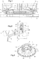
- the fiber drawing set shown on figure 1 groups together the various elements used in fiber production techniques by internal centrifugation and drawing by means of a hot gas stream.
- the invention relates to the centrifuge 1 and its attachment to the shaft 2, the other aforementioned constituent elements of the fiberizing assembly will not be further commented on.
- the shaft 2 is hollow and the material such as glass intended to form the fibers flows from the supply means (furnace, front body, die) according to the arrow F in the shaft 2 into the centrifuge 1 .
- the centrifuge 1 comprises a fixing body 10, usually called “tulip”, making it possible to fix the centrifuge to the shaft 2, a fiberizing plate 6, without bottom, and a basket 7.
- a fixing body 10 usually called "tulip”
- the fiberizing plate is provided with a bottom; the centrifuge then does not have a basket and the molten glass falls directly into the bottom of the fiberizing where it is distributed by centrifugation near the peripheral wall of the fiberizing plate.
- the tulip 10 comprises a hub 11 and a rim 12 in the form of a disc integral with the lower end of the hub. In the mounted position of the centrifuge, the rim 12 is disposed horizontally and in a lower position relative to the hub.
- the attachment of the centrifuge 1 to the hollow shaft 2 is provided by the hub 11 and will be described in detail below.
- the fiberizing plate 6 is fixed to the rim 12.
- the basket 7 is housed inside the plate and is suspended from the rim 12, in line with the hub 11.
- the stretchable molten material passing through the hollow shaft 2 spreads over the bottom of the basket 7.
- the basket 7 is also driven in rotation via the attachment of the centrifuge to the rotating shaft 2.
- the rotation of the basket causes the projection of the molten material on its peripheral wall 70 which is pierced with orifices and from there the projection in the form of bulky threads 71.
- the threads 71 are projected onto the peripheral wall 60 of the plate 6
- This peripheral wall 60 is pierced with a large number of orifices through which the material passes, forming relatively fine so-called “primary” filaments. It is these primary filaments which are projected out of the plate 6 of the centrifuge in the gas stream emitted by the burner 3. Under the action of this current, the drawing of the primary filaments leads to the formation of fibers.
- the centrifugation device 1 illustrated in figure 2 is fixed to the shaft 2 via fixing parts 8, the latter being integral with the tulip 10 and arranged in isolation around the periphery of the hub 11, and via an interface ring 9.
- the interface ring 9 (also shown on figure 9 ) makes it possible to mount the centrifugation device 1 of the invention on the shaft 2 of an existing fiber drawing assembly. Indeed, today, a centrifugation device is mounted by screwing around the shaft 2 which is threaded, which is not the case for the centrifugation device of the invention which uses the parts 8 for fixing. .
- the interface ring 9 has a tapped or threaded inner wall 90, as visible in the detail view of the figure 8 , to cooperate by screwing with the existing thread or internal thread 22 of the shaft 2 (see figure 2 ).
- a clamping screw 91 is placed in the upper part of the ring 9 and passes through its thickness to be in contact with the shaft 2, reinforcing the locking of the ring 9 on the shaft 2.
- the fasteners 8 form means for retaining and locking the centrifugation device 1 mounted on the shaft 2, here via the interface ring 9.
- the centrifugation device 1 also comprises unlocking means which comprise elastic means 8B (visible in more detail on the figures 4 and 7 ) with which the fasteners 8 are intended to cooperate for their locking in the unlocked position, as will be explained below.
- unlocking means comprise elastic means 8B (visible in more detail on the figures 4 and 7 ) with which the fasteners 8 are intended to cooperate for their locking in the unlocked position, as will be explained below.
- fasteners 8 There are at least two fasteners 8. They are distributed uniformly over the circular periphery of the hub 11 in order to balance the centrifuge by weight and provide a balanced assembly on the shaft.
- the example of a tulip presented comprises three fasteners arranged equidistantly, of which only two are visible.
- each part is in the form of a pawl intended to cooperate with a toothed surface 92 of the rack type arranged on the interface ring 9, itself fixed to the shaft 2.
- the ratchet mechanism of the invention ensures a locked engagement of the centrifugation device by the cooperation of the pawls in the recesses / hollows of the facing rack, with the impossibility of returning to a previous position, here in a lower position, ensuring to the centrifugation device not to be able to descend and consequently to detach itself from the shaft.
- the hub 11 of the centrifugation device of the invention is therefore in no way threaded since the fixing is done via the pawls 8.
- the notched surface 92 is machined on the outer face of the wall of the interface ring 9.
- the shaft 2 can be directly machined to include, on its outer face, the notched surface 92 in order to direct cooperation with the pawls, which eliminates the need for the interface ring.
- the entire description concerning this notched surface 92 and the cooperation with the fixing parts 8 is therefore also valid in the absence of interface ring 9.
- the notched surface 92 can be machined over the entire periphery of the ring in order to be able to mount the device and to ensure cooperation with the pawls by dispensing with the positioning of the toothed surface relative to the pawls, this notched surface thus being systematically opposite the pawls when mounting the hub 11 around the ring 9.
- the notched surface 92 may also be present only in a localized manner around the periphery of the ring (as illustrated on the figure 9 ), in forming in successive parallel planes, transverse to the cylindrical axis of the ring, and in each plane, a number of grooves corresponding to the number of pawls.
- On the figure 10 is illustrated a groove 95 in a plane transverse to the cylindrical axis of the interface ring 9, in which is engaged a male element 8A of a pawl 8.
- the ring then comprises for each of the horizontal planes parallel and equidistant, three grooves distributed equidistant around the circular perimeter.
- the notched surface 92 extends over a sufficient height to ensure the height adjustment of the hub 11 and therefore of the fiberizing plate 6 relative to the burner 3. This height is for example of the order of 15 mm.
- the toothed surface 92 is of the rack type, preferably serrated. It is provided ( figure 7 ) an alternation of teeth 92A and recesses 92B parallel and transverse to the axial direction of the ring 9 (of the shaft 2), the recesses forming female elements for cooperation with the pawls 8.
- the pitch of the rack that is to say the pitch between each tooth, is preferably between 1 and 2 mm, in particular of the order of a millimeter, to ensure optimum precision in adjusting the height of the hub 11 and therefore the distance separating the fiberizing plate from the burner.
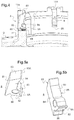
- a ratchet 8 as shown in isolation on the figures 5a and 5b , is now described next to figures 3 , 4 and 6 to 8 in position integral with the hub 11.
- Each ratchet 8 ( figures 5a, 5b and 7 ) has a body of generally substantially parallelepipedal and oblong longitudinal axis X, extending longitudinally parallel to the hub 11 in the closed position.
- the body has a so-called inner longitudinal face 80 facing the interior of the hub 11 (and therefore facing the interface ring 9), an opposite longitudinal face 81 said to be outer, a lower face 82, an upper opposite face 83 and lateral and opposite longitudinal faces 84 and 85.
- Each pawl 8 is fixed near its lower end in the thickness of the hub 11 along a pivot axis 88 perpendicular to the longitudinal axis of the hub.
- the hub 11 comprises, in its thickness, lights 11A ( figures 3 and 4 ) housing the pawls 8.
- the slot 11A guarantees the passage of a male element 8A intended for cooperation with the notched surface 92, and on the outside, it allows the pawl to swing into its open position .
- the lower cross member 8A (the male element) has a geometry of pointed section to cooperate with the recesses 92B of triangular section of the notched surface 92.
- the lower cross member 8A (the male element) has a width (part engaged in the male element) of the order of 10 mm and a height of the order of 1 mm. These dimensions could be more important. However, they prove to be sufficient considering three pawls on the hub 11 to lock the centrifugation device 1 of usual dimensions (hub for example having an outer diameter of the order of 140 mm and the fiberizing plate having for example a diameter of 400 mm) and ensure over time its mechanical strength despite the very high speed of rotation.
- the actuation of the bevelled upper surface 83 of a pawl 8 is made mechanically by resting on an upper stop 93, which is the upper part of the interface ring 9.
- This stop is peripheral over the whole of the circumference of the ring.
- the ring 9 further comprises a peripheral groove 94 bordered on the outside by the stop 93 forming a shoulder relative to the groove.
- the elastic means 8B are implemented thanks to the lug 86 cooperating with the means elastic bands 8B.
- the elastic means 8B are here in the form of a leaf spring which is fixed to the base of the hub 11 and comprises a spoiler 89 directed upwards and in front of which the lug 86 is positioned.
- the lug 86 passes behind the spoiler 89 which then retains the pawl in the open position. The descent of the tulip can then be operated.
- the pawls 8 are actuated to put them in the closed position if they were open (the operator only having to press on each of the outer faces 81 of the pawls.
- the operator has taken care to arrange a wedge under the burner 3, the thickness of which corresponds to the desired distance between the burner and the plate 6 once the tulip 10 carrying the plate 6 is mounted.
- the operator lifts the tulip 10 with the plate 6, bringing the tulip to the right of the shaft 2 and the interface ring 9. He fits the hub 11 around the ring 9, and mounts the hub by performing a vertical translation upwards, until the pawls 8 clash on the notched surface 92.
- the lower cross member 8A of each pawl 8 engages in the first recess 92B (the lower one) of the notched surface or the first groove.
- the operator continues his vertical thrust of the centrifugation device 1 to raise it step by step, each pawl engaging successively and concomitantly in the successive hollows of the notched surface, without being able to descend.
- the rise is carried out up to a notch which corresponds to the moment when the plate 6 butts against the wedge which has been associated with the burner. The operator can no longer raise the device higher.
- the centrifugation device 1 is then at the desired height and is locked. The assembly is finished. The wedge can be removed.
- the assembly is therefore very simple and quick to implement.
- the operator performs a vertical pushing movement on the device, to continue the rise of the notches, until the pawls 8 abut by their bevelled surface 83 on the upper stop 93 of the shaft, rotating the pawls, disengaging the crossmembers 8A (the male elements) from the notched surface 92 ( figure 8 ), the upper end 83A of the pawls being housed in the annular groove 94.
- the bevelled surface 83 has an inclination angle which corresponds to the tilting angle to be imposed on the pawl so that the lug 86 can pass behind the spoiler 89 of the elastic means 8B, and lock the pawls 8 in the open position.
Landscapes
- Engineering & Computer Science (AREA)
- Chemical & Material Sciences (AREA)
- Life Sciences & Earth Sciences (AREA)
- General Life Sciences & Earth Sciences (AREA)
- Geochemistry & Mineralogy (AREA)
- Manufacturing & Machinery (AREA)
- Materials Engineering (AREA)
- Organic Chemistry (AREA)
- Centrifugal Separators (AREA)
- External Artificial Organs (AREA)
- Separation Using Semi-Permeable Membranes (AREA)
Claims (15)
- Interne Zentrifugierungsvorrichtung (1) zur Bildung von Fasern, insbesondere Mineralfasern, umfassend eine Faserziehplatte (6), versehen mit einer Umfangswand (60), die von einer Vielzahl von Öffnungen durchbohrt ist, einen als Tulpe bezeichneten Träger (10) der Faserziehplatte (6), wobei die Tulpe einen zylindrischen Hohlkörper oder eine Nabe (11) und eine scheibenförmige Felge (12) um das untere Ende der Nabe herum sowie Befestigungsmittel (8) beinhaltet, die auf der Nabe angeordnet und zur Befestigung der Tulpe auf einer drehbaren Welle (2) bestimmt sind, dadurch gekennzeichnet, dass die Befestigungsmittel mindestens zwei isolierte koplanare Einsteckelemente (8A) umfassen, die aus der Innenwand der Nabe (11) herausragen und Mittel zum Halten und mechanischen Verriegeln der Vorrichtung auf der Welle (2) in Gebrauchsstellung konstituieren, wobei jedes Einsteckelement (8A) dazu bestimmt ist, mit einem Aufnahmeelement (92B) der Welle (2) oder mit einem Aufnahmeelement (92B) eines mit der Welle (2) fest verbundenen Schnittstellenrings (9) durch Einführen jedes
Einsteckelements (8A) in ein Aufnahmeelement (92B) zusammenzuwirken, wobei die Vorrichtung ferner elastische Mittel (8B) umfasst, die die Entriegelung der Vorrichtung bezüglich der Welle (2) ermöglichen. - Vorrichtung nach Anspruch 1, wobei die Befestigungsmittel (8) mindestens zwei koplanare Einsteckelemente (8A), vorzugsweise drei oder mindestens drei, die äquidistant um die Nabe (11) herum verteilt sind, oder mindestens zwei Befestigungsteile, vorzugsweise drei oder mindestens drei, die äquidistant auf dem Umfang der Nabe (11) herum verteilt sind, umfassen, wobei jedes Befestigungsteil ein Einsteckelement (8A) zum Halten und Verriegeln beinhaltet.
- Vorrichtung nach Anspruch 1 oder 2, wobei die Befestigungsmittel (8) Befestigungsteile sind, die in Form von Sperrklinken vorliegen.
- Vorrichtung nach einem der Ansprüche 2 bis 3, wobei jedes Befestigungsteil (8) innerhalb der Dicke der Nabe (11) schwenkbar montiert ist, wobei die Nabe Langlöcher (11A) zur Aufnahme der Teile umfasst, wobei jedes Teil zwei Positionen einnehmen kann, entweder eine Ruheposition, die geschlossene Position, in der das Teil parallel zum Längskörper der Nabe vorliegt, oder eine gekippte Position, die offene Position, in der das Teil geschwenkt und bezüglich der Längsachse der Nabe in einer zur Achse entgegengesetzten Richtung abgewinkelt ausgerichtet ist.
- Vorrichtung nach einem der Ansprüche 2 bis 3, wobei jedes Befestigungsteil (8) einen länglichen Körper aufweist und an seinem unteren Ende einen unteren Querträger (8A) umfasst, der aus dem Körper herausragt und das Einsteckelement, vorzugsweise einen spitzen Querschnitt aufweisend, konstituiert.
- Vorrichtung nach Anspruch 4 oder 5, wobei jedes Befestigungsteil (8) ferner ein Mittel zum Blockieren (86) des Teils in offener Position umfasst, wenn das Teil bis zu einer bestimmten Winkelposition gekippt ist, wobei im Besonderen das Mittel zum Blockieren (86) ein Vorsprung ist, der an der Unterseite des Teils und in einem Abstand zum Einsteckelement (8A) positioniert ist.
- Vorrichtung nach einem der Ansprüche 4 bis 6, wobei die elastischen Mittel (8B) zum Entriegeln aus einer Feder bestehen, die mit jedem Befestigungsteil (8) verbunden ist und geeignet ist, nach seinem Schwenken entsprechend einem bestimmten Winkel durch ein Zusammenwirken mit einem Mittel zum Blockieren (86), das Befestigungsteil in offener Position zu halten.
- Vorrichtung nach dem vorstehenden Anspruch, wobei die Feder (8B) die Form eines Blatts mit einem Deckblatt (89) aufweist, während das Mittel zum Blockieren einen Vorsprung (86) bildet, der nach dem Schwenken des Befestigungsteils (8), entsprechend einem bestimmten Winkel, hinter das Deckblatt (89) treten kann, und wobei das Deckblatt (89) dann das Befestigungsteil durch Anschlag des Vorsprungs (86) gegen das Deckblatt (89) offen hält.
- Vorrichtung nach einem der Ansprüche 2 bis 6, wobei jedes Befestigungsteil (8) an seinem oberen Ende eine abgeschrägte Oberfläche (83) aufweist, die als Auflageoberfläche dient und dazu bestimmt ist, mit einem oberen Anschlag (93) zusammenzuwirken, der fest mit der Welle (2) oder dem Schnittstellenring (9) verbunden ist.
- Faserziehbaugruppe, beinhaltend eine Hohlwelle (2), die geeignet ist, sich mit hoher Geschwindigkeit zu drehen, und eine interne
Zentrifugierungsvorrichtung (1) zur Bildung von Fasern nach einem der vorstehenden Ansprüche, wobei die Vorrichtung an der Hohlwelle (2) durch die Tulpe (10) entweder direkt auf der Welle (2) oder mittels eines Schnittstellenrings (9) befestigt ist, der seinerseits um die Welle (2) herum aufgeschraubt ist, wobei die Welle (2) oder der Schnittstellenring (9) an ihrer Außenwand Aufnahmeelemente (92B; 95) umfassen, die mit den Einsteckelementen (8A) zusammenwirken. - Baugruppe nach dem vorstehenden Anspruch, wobei die Aufnahmeelemente (92B) des Schnittstellenrings (9) oder der Welle (2) eine gezahnte Oberfläche (92) der Zahnstangen- oder Sägezahnart bilden, wobei die gezahnte Oberfläche (92) im Besonderen mit einem Wechsel von Zähnen (92A) und Vertiefungen (92B) versehen ist, die parallel und in Querrichtung zur Längsachse des Rings (9) oder der Welle (2) vorliegen, wobei die Vertiefungen (92B) die Aufnahmeelemente bilden, und wobei sich die gezahnte Oberfläche (92) vorzugsweise entlang der Längsachse der Welle (2) oder des Rings (9) über eine Entfernung in der Größenordnung von 15 mm erstreckt.
- Baugruppe nach Anspruch 10, wobei die Aufnahmeelemente (92B) des Schnittstellenrings (9) oder der Welle (2) mit konstantem Abstand in Ebenen senkrecht zur Längsachse der Welle (2) oder des Rings (9) angeordnet sind, wobei jede Ebene entweder ein kreisförmiges kontinuierliches Aufnahmeelement oder mehrere diskontinuierliche und äquidistante Aufnahmeelemente beinhaltet, wobei der konstante Abstand der Aufnahmeelemente der aufeinanderfolgenden Ebenen vorzugsweise im Bereich zwischen 1 und 2 mm, insbesondere im Millimeterbereich, liegt.
- Baugruppe nach Anspruch 11 oder 12, wobei die Zähne (92A) und die Vertiefungen (92B) des Schnittstellenrings (9) oder der Welle (2) in einer vertikalen Ebene einen Querschnitt mit dreieckiger Geometrie aufweisen, wobei die Spitzen in horizontalen Ebenen parallel zueinander vorliegen oder wesentlich nach oben geneigt sind, während die Einsteckelemente (8A) eine Geometrie des gegenseitigen Zusammenwirkens mit den Vertiefungen (92B) aufweisen.
- Baugruppe nach einem der Ansprüche 10 bis 13, wobei die Welle (2) oder der Schnittstellenring (9) auf der Oberseite in einer Entfernung zu den Aufnahmeelementen (92B) und in einer äußeren Ebene, die bezüglich der die Aufnahmeelemente enthaltenden Ebene versetzt ist, eine nach unten gerichtete Umfangsnut (94) mit einer Konkavität umfasst, die eine Schulter begrenzt, die einen oberer Anschlag (93) zum Zusammenwirken mit dem oberen Abschnitt der Befestigungsteile (8), im Besonderen entlang einer abgeschrägten oberen Oberfläche (83) der Befestigungsteile, konstituiert.
- Verwendung einer internen Zentrifugierungsvorrichtung (1) zur Bildung von Fasern nach einem der Ansprüche 1 bis 9 oder einer Faserziehbaugruppe nach einem der Ansprüche 10 bis 14 zum Herstellen von Fasern, im Besonderen von Mineralfasern.
Applications Claiming Priority (2)
| Application Number | Priority Date | Filing Date | Title |
|---|---|---|---|
| FR1663030A FR3060555B1 (fr) | 2016-12-21 | 2016-12-21 | Dispositif de centrifugation interne pour la formation de fibres |
| PCT/FR2017/053790 WO2018115773A1 (fr) | 2016-12-21 | 2017-12-21 | Dispositif de centrifugation interne pour la formation de fibres |
Publications (2)
| Publication Number | Publication Date |
|---|---|
| EP3558882A1 EP3558882A1 (de) | 2019-10-30 |
| EP3558882B1 true EP3558882B1 (de) | 2020-09-30 |
Family
ID=58455203
Family Applications (1)
| Application Number | Title | Priority Date | Filing Date |
|---|---|---|---|
| EP17832276.4A Active EP3558882B1 (de) | 2016-12-21 | 2017-12-21 | Interne zentrifugierende vorrichtung zur formung von fasern |
Country Status (4)
| Country | Link |
|---|---|
| EP (1) | EP3558882B1 (de) |
| AR (1) | AR110355A1 (de) |
| FR (1) | FR3060555B1 (de) |
| WO (1) | WO2018115773A1 (de) |
Families Citing this family (1)
| Publication number | Priority date | Publication date | Assignee | Title |
|---|---|---|---|---|
| EP3844114A1 (de) | 2018-08-27 | 2021-07-07 | Knauf Insulation, Inc. | Drehspinnvorrichtungen, verfahren und systeme zur herstellung von fasern aus geschmolzenem material |
Family Cites Families (2)
| Publication number | Priority date | Publication date | Assignee | Title |
|---|---|---|---|---|
| US3026563A (en) * | 1956-04-18 | 1962-03-27 | Owens Corning Fiberglass Corp | Apparatus for processing heatsoftenable materials |
| US9624123B2 (en) * | 2014-08-07 | 2017-04-18 | Knauf Insulation, Inc. | Multi-component rotary spinner apparatuses systems and methods for producing fiber from molten material |
-
2016
- 2016-12-21 FR FR1663030A patent/FR3060555B1/fr not_active Expired - Fee Related
-
2017
- 2017-12-12 AR ARP170103478A patent/AR110355A1/es unknown
- 2017-12-21 WO PCT/FR2017/053790 patent/WO2018115773A1/fr not_active Ceased
- 2017-12-21 EP EP17832276.4A patent/EP3558882B1/de active Active
Non-Patent Citations (1)
| Title |
|---|
| None * |
Also Published As
| Publication number | Publication date |
|---|---|
| EP3558882A1 (de) | 2019-10-30 |
| FR3060555A1 (fr) | 2018-06-22 |
| AR110355A1 (es) | 2019-03-20 |
| FR3060555B1 (fr) | 2019-01-25 |
| WO2018115773A1 (fr) | 2018-06-28 |
Similar Documents
| Publication | Publication Date | Title |
|---|---|---|
| EP4433360B1 (de) | Modul zur montage einer bläserschaufel einer turbomaschine | |
| EP1880789B1 (de) | Verfahren zur Herstellung einer einstückigen Leitschaufelplatte (BLISK) | |
| EP3908738B1 (de) | Montage- und demontageverfahren einer turbinendeckbandanordnung | |
| EP2366060B1 (de) | Gebläse für ein Turbotriebwerk mit einem Auswuchtsystem mit Blindlöchern zur Unterbringung von Gewichten und zugehöriges Turbotriebwerk | |
| EP0442238B1 (de) | Zusammengesetztes, rotierendes, kreisförmiges Schneidwerkzeug | |
| FR2956377A1 (fr) | Dispositif de commande par cremalleres de la position angulaire d'aubes pivotantes de turbomachine | |
| WO2011045520A1 (fr) | Roue de turbine equipee d'un jonc de retenue axiale verrouillant des pales par rapport a un disque | |
| EP2423764A1 (de) | Vorrichtung zum Messen des Drehmomentes einer Spirale | |
| EP3558882B1 (de) | Interne zentrifugierende vorrichtung zur formung von fasern | |
| EP0197830A1 (de) | Verfahren zur Herstellung eines Reflektors für Projektor, insbesondere für Kraftfahrzeug, durch Spritzgiessen von zwei Stoffen, Form zur Durchführung dieses Verfahrens und erhaltenes Produkt | |
| FR2734152A1 (fr) | Dispositif de securite et de controle de verrouillage d'un moyeu de roue, notamment pour fauteuils roulants | |
| FR3057908A1 (fr) | Ensemble rotatif d'une turbomachine muni d'un systeme de maintien axial d'une aube | |
| EP0078203A1 (de) | Sicherheitsgurtaufwickelautomat | |
| FR2667308A1 (fr) | Dispositif annulaire de trempe. | |
| FR2763583A1 (fr) | Plaque vitroceramique et son procede de fabrication | |
| FR2872399A1 (fr) | Methode de fabrication d'un plateau pour robot culinaire destine a diviser des produits alimentaires par passage a travers une grille, plateau associe et cadre permettant la fabrication du plateau | |
| EP3585510B1 (de) | Gasinjektionselement für eine fluid-catalytic-cracking-einheit und mit diesem gasinjektionselement ausgestattetes gasverteilungssystem | |
| FR2624849A1 (fr) | Dispositif de reglage de l'espace entre deux plaques, en particulier un moule de profilage ajustable pour la fabrication de pare-brise | |
| EP3652121B1 (de) | Faserbildende platte | |
| EP3391154B1 (de) | Schwingsystem für eine uhr | |
| EP4228964B1 (de) | Befestigungsanordnung für eine turbinenmotorschaufel | |
| EP1814684B1 (de) | Spitzenfestklemmanordnung | |
| FR2967223A1 (fr) | Element de suspension temporaire, et procedes de fixation et de demontage utilisant ledit element | |
| FR2831838A1 (fr) | Broyeur centrifuge | |
| EP3569828A1 (de) | Metalleinsatz zum aufformen zur lokalen verstärkung eines formteils eines luftfahrzeugmotors |
Legal Events
| Date | Code | Title | Description |
|---|---|---|---|
| STAA | Information on the status of an ep patent application or granted ep patent |
Free format text: STATUS: UNKNOWN |
|
| STAA | Information on the status of an ep patent application or granted ep patent |
Free format text: STATUS: THE INTERNATIONAL PUBLICATION HAS BEEN MADE |
|
| PUAI | Public reference made under article 153(3) epc to a published international application that has entered the european phase |
Free format text: ORIGINAL CODE: 0009012 |
|
| STAA | Information on the status of an ep patent application or granted ep patent |
Free format text: STATUS: REQUEST FOR EXAMINATION WAS MADE |
|
| 17P | Request for examination filed |
Effective date: 20190722 |
|
| AK | Designated contracting states |
Kind code of ref document: A1 Designated state(s): AL AT BE BG CH CY CZ DE DK EE ES FI FR GB GR HR HU IE IS IT LI LT LU LV MC MK MT NL NO PL PT RO RS SE SI SK SM TR |
|
| AX | Request for extension of the european patent |
Extension state: BA ME |
|
| DAV | Request for validation of the european patent (deleted) | ||
| DAX | Request for extension of the european patent (deleted) | ||
| GRAP | Despatch of communication of intention to grant a patent |
Free format text: ORIGINAL CODE: EPIDOSNIGR1 |
|
| STAA | Information on the status of an ep patent application or granted ep patent |
Free format text: STATUS: GRANT OF PATENT IS INTENDED |
|
| INTG | Intention to grant announced |
Effective date: 20200423 |
|
| RAP1 | Party data changed (applicant data changed or rights of an application transferred) |
Owner name: SAINT-GOBAIN ISOVER |
|
| GRAS | Grant fee paid |
Free format text: ORIGINAL CODE: EPIDOSNIGR3 |
|
| GRAA | (expected) grant |
Free format text: ORIGINAL CODE: 0009210 |
|
| STAA | Information on the status of an ep patent application or granted ep patent |
Free format text: STATUS: THE PATENT HAS BEEN GRANTED |
|
| AK | Designated contracting states |
Kind code of ref document: B1 Designated state(s): AL AT BE BG CH CY CZ DE DK EE ES FI FR GB GR HR HU IE IS IT LI LT LU LV MC MK MT NL NO PL PT RO RS SE SI SK SM TR |
|
| REG | Reference to a national code |
Ref country code: GB Ref legal event code: FG4D Free format text: NOT ENGLISH Ref country code: CH Ref legal event code: EP |
|
| REG | Reference to a national code |
Ref country code: AT Ref legal event code: REF Ref document number: 1318629 Country of ref document: AT Kind code of ref document: T Effective date: 20201015 Ref country code: DE Ref legal event code: R096 Ref document number: 602017024768 Country of ref document: DE |
|
| REG | Reference to a national code |
Ref country code: IE Ref legal event code: FG4D Free format text: LANGUAGE OF EP DOCUMENT: FRENCH |
|
| REG | Reference to a national code |
Ref country code: SE Ref legal event code: TRGR |
|
| PG25 | Lapsed in a contracting state [announced via postgrant information from national office to epo] |
Ref country code: NO Free format text: LAPSE BECAUSE OF FAILURE TO SUBMIT A TRANSLATION OF THE DESCRIPTION OR TO PAY THE FEE WITHIN THE PRESCRIBED TIME-LIMIT Effective date: 20201230 Ref country code: GR Free format text: LAPSE BECAUSE OF FAILURE TO SUBMIT A TRANSLATION OF THE DESCRIPTION OR TO PAY THE FEE WITHIN THE PRESCRIBED TIME-LIMIT Effective date: 20201231 Ref country code: BG Free format text: LAPSE BECAUSE OF FAILURE TO SUBMIT A TRANSLATION OF THE DESCRIPTION OR TO PAY THE FEE WITHIN THE PRESCRIBED TIME-LIMIT Effective date: 20201230 Ref country code: HR Free format text: LAPSE BECAUSE OF FAILURE TO SUBMIT A TRANSLATION OF THE DESCRIPTION OR TO PAY THE FEE WITHIN THE PRESCRIBED TIME-LIMIT Effective date: 20200930 Ref country code: FI Free format text: LAPSE BECAUSE OF FAILURE TO SUBMIT A TRANSLATION OF THE DESCRIPTION OR TO PAY THE FEE WITHIN THE PRESCRIBED TIME-LIMIT Effective date: 20200930 |
|
| REG | Reference to a national code |
Ref country code: AT Ref legal event code: MK05 Ref document number: 1318629 Country of ref document: AT Kind code of ref document: T Effective date: 20200930 |
|
| PG25 | Lapsed in a contracting state [announced via postgrant information from national office to epo] |
Ref country code: RS Free format text: LAPSE BECAUSE OF FAILURE TO SUBMIT A TRANSLATION OF THE DESCRIPTION OR TO PAY THE FEE WITHIN THE PRESCRIBED TIME-LIMIT Effective date: 20200930 Ref country code: LV Free format text: LAPSE BECAUSE OF FAILURE TO SUBMIT A TRANSLATION OF THE DESCRIPTION OR TO PAY THE FEE WITHIN THE PRESCRIBED TIME-LIMIT Effective date: 20200930 |
|
| REG | Reference to a national code |
Ref country code: NL Ref legal event code: MP Effective date: 20200930 |
|
| REG | Reference to a national code |
Ref country code: LT Ref legal event code: MG4D |
|
| PG25 | Lapsed in a contracting state [announced via postgrant information from national office to epo] |
Ref country code: LT Free format text: LAPSE BECAUSE OF FAILURE TO SUBMIT A TRANSLATION OF THE DESCRIPTION OR TO PAY THE FEE WITHIN THE PRESCRIBED TIME-LIMIT Effective date: 20200930 Ref country code: SM Free format text: LAPSE BECAUSE OF FAILURE TO SUBMIT A TRANSLATION OF THE DESCRIPTION OR TO PAY THE FEE WITHIN THE PRESCRIBED TIME-LIMIT Effective date: 20200930 Ref country code: PT Free format text: LAPSE BECAUSE OF FAILURE TO SUBMIT A TRANSLATION OF THE DESCRIPTION OR TO PAY THE FEE WITHIN THE PRESCRIBED TIME-LIMIT Effective date: 20210201 Ref country code: RO Free format text: LAPSE BECAUSE OF FAILURE TO SUBMIT A TRANSLATION OF THE DESCRIPTION OR TO PAY THE FEE WITHIN THE PRESCRIBED TIME-LIMIT Effective date: 20200930 Ref country code: CZ Free format text: LAPSE BECAUSE OF FAILURE TO SUBMIT A TRANSLATION OF THE DESCRIPTION OR TO PAY THE FEE WITHIN THE PRESCRIBED TIME-LIMIT Effective date: 20200930 Ref country code: EE Free format text: LAPSE BECAUSE OF FAILURE TO SUBMIT A TRANSLATION OF THE DESCRIPTION OR TO PAY THE FEE WITHIN THE PRESCRIBED TIME-LIMIT Effective date: 20200930 |
|
| PG25 | Lapsed in a contracting state [announced via postgrant information from national office to epo] |
Ref country code: AT Free format text: LAPSE BECAUSE OF FAILURE TO SUBMIT A TRANSLATION OF THE DESCRIPTION OR TO PAY THE FEE WITHIN THE PRESCRIBED TIME-LIMIT Effective date: 20200930 Ref country code: AL Free format text: LAPSE BECAUSE OF FAILURE TO SUBMIT A TRANSLATION OF THE DESCRIPTION OR TO PAY THE FEE WITHIN THE PRESCRIBED TIME-LIMIT Effective date: 20200930 Ref country code: ES Free format text: LAPSE BECAUSE OF FAILURE TO SUBMIT A TRANSLATION OF THE DESCRIPTION OR TO PAY THE FEE WITHIN THE PRESCRIBED TIME-LIMIT Effective date: 20200930 Ref country code: PL Free format text: LAPSE BECAUSE OF FAILURE TO SUBMIT A TRANSLATION OF THE DESCRIPTION OR TO PAY THE FEE WITHIN THE PRESCRIBED TIME-LIMIT Effective date: 20200930 Ref country code: IS Free format text: LAPSE BECAUSE OF FAILURE TO SUBMIT A TRANSLATION OF THE DESCRIPTION OR TO PAY THE FEE WITHIN THE PRESCRIBED TIME-LIMIT Effective date: 20210130 |
|
| PG25 | Lapsed in a contracting state [announced via postgrant information from national office to epo] |
Ref country code: NL Free format text: LAPSE BECAUSE OF FAILURE TO SUBMIT A TRANSLATION OF THE DESCRIPTION OR TO PAY THE FEE WITHIN THE PRESCRIBED TIME-LIMIT Effective date: 20200930 Ref country code: SK Free format text: LAPSE BECAUSE OF FAILURE TO SUBMIT A TRANSLATION OF THE DESCRIPTION OR TO PAY THE FEE WITHIN THE PRESCRIBED TIME-LIMIT Effective date: 20200930 |
|
| REG | Reference to a national code |
Ref country code: DE Ref legal event code: R097 Ref document number: 602017024768 Country of ref document: DE |
|
| REG | Reference to a national code |
Ref country code: CH Ref legal event code: PL |
|
| PLBE | No opposition filed within time limit |
Free format text: ORIGINAL CODE: 0009261 |
|
| STAA | Information on the status of an ep patent application or granted ep patent |
Free format text: STATUS: NO OPPOSITION FILED WITHIN TIME LIMIT |
|
| PG25 | Lapsed in a contracting state [announced via postgrant information from national office to epo] |
Ref country code: MC Free format text: LAPSE BECAUSE OF FAILURE TO SUBMIT A TRANSLATION OF THE DESCRIPTION OR TO PAY THE FEE WITHIN THE PRESCRIBED TIME-LIMIT Effective date: 20200930 Ref country code: DK Free format text: LAPSE BECAUSE OF FAILURE TO SUBMIT A TRANSLATION OF THE DESCRIPTION OR TO PAY THE FEE WITHIN THE PRESCRIBED TIME-LIMIT Effective date: 20200930 |
|
| REG | Reference to a national code |
Ref country code: BE Ref legal event code: MM Effective date: 20201231 |
|
| 26N | No opposition filed |
Effective date: 20210701 |
|
| PG25 | Lapsed in a contracting state [announced via postgrant information from national office to epo] |
Ref country code: LU Free format text: LAPSE BECAUSE OF NON-PAYMENT OF DUE FEES Effective date: 20201221 Ref country code: IE Free format text: LAPSE BECAUSE OF NON-PAYMENT OF DUE FEES Effective date: 20201221 |
|
| PG25 | Lapsed in a contracting state [announced via postgrant information from national office to epo] |
Ref country code: CH Free format text: LAPSE BECAUSE OF NON-PAYMENT OF DUE FEES Effective date: 20201231 Ref country code: SI Free format text: LAPSE BECAUSE OF FAILURE TO SUBMIT A TRANSLATION OF THE DESCRIPTION OR TO PAY THE FEE WITHIN THE PRESCRIBED TIME-LIMIT Effective date: 20200930 Ref country code: LI Free format text: LAPSE BECAUSE OF NON-PAYMENT OF DUE FEES Effective date: 20201231 |
|
| PG25 | Lapsed in a contracting state [announced via postgrant information from national office to epo] |
Ref country code: IS Free format text: LAPSE BECAUSE OF FAILURE TO SUBMIT A TRANSLATION OF THE DESCRIPTION OR TO PAY THE FEE WITHIN THE PRESCRIBED TIME-LIMIT Effective date: 20210130 Ref country code: TR Free format text: LAPSE BECAUSE OF FAILURE TO SUBMIT A TRANSLATION OF THE DESCRIPTION OR TO PAY THE FEE WITHIN THE PRESCRIBED TIME-LIMIT Effective date: 20200930 Ref country code: MT Free format text: LAPSE BECAUSE OF FAILURE TO SUBMIT A TRANSLATION OF THE DESCRIPTION OR TO PAY THE FEE WITHIN THE PRESCRIBED TIME-LIMIT Effective date: 20200930 Ref country code: CY Free format text: LAPSE BECAUSE OF FAILURE TO SUBMIT A TRANSLATION OF THE DESCRIPTION OR TO PAY THE FEE WITHIN THE PRESCRIBED TIME-LIMIT Effective date: 20200930 |
|
| PG25 | Lapsed in a contracting state [announced via postgrant information from national office to epo] |
Ref country code: MK Free format text: LAPSE BECAUSE OF FAILURE TO SUBMIT A TRANSLATION OF THE DESCRIPTION OR TO PAY THE FEE WITHIN THE PRESCRIBED TIME-LIMIT Effective date: 20200930 |
|
| PG25 | Lapsed in a contracting state [announced via postgrant information from national office to epo] |
Ref country code: BE Free format text: LAPSE BECAUSE OF NON-PAYMENT OF DUE FEES Effective date: 20201231 |
|
| P01 | Opt-out of the competence of the unified patent court (upc) registered |
Effective date: 20230421 |
|
| PGFP | Annual fee paid to national office [announced via postgrant information from national office to epo] |
Ref country code: DE Payment date: 20251104 Year of fee payment: 9 |
|
| PGFP | Annual fee paid to national office [announced via postgrant information from national office to epo] |
Ref country code: GB Payment date: 20251030 Year of fee payment: 9 |
|
| PGFP | Annual fee paid to national office [announced via postgrant information from national office to epo] |
Ref country code: IT Payment date: 20251121 Year of fee payment: 9 |
|
| PGFP | Annual fee paid to national office [announced via postgrant information from national office to epo] |
Ref country code: FR Payment date: 20251110 Year of fee payment: 9 |
|
| PGFP | Annual fee paid to national office [announced via postgrant information from national office to epo] |
Ref country code: SE Payment date: 20251112 Year of fee payment: 9 |