EP3558838B1 - Ausgabevorrichtung für eine trinkflasche - Google Patents
Ausgabevorrichtung für eine trinkflasche Download PDFInfo
- Publication number
- EP3558838B1 EP3558838B1 EP17882357.1A EP17882357A EP3558838B1 EP 3558838 B1 EP3558838 B1 EP 3558838B1 EP 17882357 A EP17882357 A EP 17882357A EP 3558838 B1 EP3558838 B1 EP 3558838B1
- Authority
- EP
- European Patent Office
- Prior art keywords
- cartridge
- aperture
- bottle
- beverage container
- opening
- Prior art date
- Legal status (The legal status is an assumption and is not a legal conclusion. Google has not performed a legal analysis and makes no representation as to the accuracy of the status listed.)
- Active
Links
- 235000013361 beverage Nutrition 0.000 claims description 64
- 238000009472 formulation Methods 0.000 claims description 47
- 239000000203 mixture Substances 0.000 claims description 47
- 238000007789 sealing Methods 0.000 claims description 40
- 239000012528 membrane Substances 0.000 claims description 34
- 239000004615 ingredient Substances 0.000 claims description 22
- 239000007788 liquid Substances 0.000 claims description 9
- 230000007246 mechanism Effects 0.000 description 33
- 230000015572 biosynthetic process Effects 0.000 description 14
- 238000005755 formation reaction Methods 0.000 description 14
- 238000000034 method Methods 0.000 description 9
- 229920003023 plastic Polymers 0.000 description 7
- 239000004033 plastic Substances 0.000 description 7
- 230000008901 benefit Effects 0.000 description 4
- 230000001681 protective effect Effects 0.000 description 4
- 230000002093 peripheral effect Effects 0.000 description 3
- 238000003825 pressing Methods 0.000 description 3
- 239000000853 adhesive Substances 0.000 description 2
- 230000001070 adhesive effect Effects 0.000 description 2
- 230000035622 drinking Effects 0.000 description 2
- 239000003651 drinking water Substances 0.000 description 2
- 238000007373 indentation Methods 0.000 description 2
- 238000004519 manufacturing process Methods 0.000 description 2
- 230000000717 retained effect Effects 0.000 description 2
- 235000011496 sports drink Nutrition 0.000 description 2
- 238000003466 welding Methods 0.000 description 2
- WQZGKKKJIJFFOK-GASJEMHNSA-N Glucose Natural products OC[C@H]1OC(O)[C@H](O)[C@@H](O)[C@@H]1O WQZGKKKJIJFFOK-GASJEMHNSA-N 0.000 description 1
- 230000009471 action Effects 0.000 description 1
- 235000012206 bottled water Nutrition 0.000 description 1
- 230000000295 complement effect Effects 0.000 description 1
- 238000011109 contamination Methods 0.000 description 1
- 230000001419 dependent effect Effects 0.000 description 1
- 230000000249 desinfective effect Effects 0.000 description 1
- 235000005911 diet Nutrition 0.000 description 1
- 230000000378 dietary effect Effects 0.000 description 1
- 235000015872 dietary supplement Nutrition 0.000 description 1
- 235000020188 drinking water Nutrition 0.000 description 1
- 239000003814 drug Substances 0.000 description 1
- 238000005516 engineering process Methods 0.000 description 1
- 235000020774 essential nutrients Nutrition 0.000 description 1
- 239000003925 fat Substances 0.000 description 1
- 238000005429 filling process Methods 0.000 description 1
- 239000000796 flavoring agent Substances 0.000 description 1
- 235000019634 flavors Nutrition 0.000 description 1
- 239000008103 glucose Substances 0.000 description 1
- 239000003292 glue Substances 0.000 description 1
- 239000008187 granular material Substances 0.000 description 1
- 239000012669 liquid formulation Substances 0.000 description 1
- 239000000463 material Substances 0.000 description 1
- 238000002844 melting Methods 0.000 description 1
- 230000008018 melting Effects 0.000 description 1
- 230000004048 modification Effects 0.000 description 1
- 238000012986 modification Methods 0.000 description 1
- 238000000465 moulding Methods 0.000 description 1
- 238000010137 moulding (plastic) Methods 0.000 description 1
- 230000037257 muscle growth Effects 0.000 description 1
- 235000016709 nutrition Nutrition 0.000 description 1
- 229920000642 polymer Polymers 0.000 description 1
- 239000000843 powder Substances 0.000 description 1
- 239000012254 powdered material Substances 0.000 description 1
- 230000008569 process Effects 0.000 description 1
- 235000018102 proteins Nutrition 0.000 description 1
- 102000004169 proteins and genes Human genes 0.000 description 1
- 108090000623 proteins and genes Proteins 0.000 description 1
- 238000004064 recycling Methods 0.000 description 1
- 238000000926 separation method Methods 0.000 description 1
- 238000001228 spectrum Methods 0.000 description 1
- 239000010902 straw Substances 0.000 description 1
- 210000004243 sweat Anatomy 0.000 description 1
- 239000003826 tablet Substances 0.000 description 1
- 235000013343 vitamin Nutrition 0.000 description 1
- 229940088594 vitamin Drugs 0.000 description 1
- 229930003231 vitamin Natural products 0.000 description 1
- 239000011782 vitamin Substances 0.000 description 1
Images



Classifications
-
- B—PERFORMING OPERATIONS; TRANSPORTING
- B65—CONVEYING; PACKING; STORING; HANDLING THIN OR FILAMENTARY MATERIAL
- B65D—CONTAINERS FOR STORAGE OR TRANSPORT OF ARTICLES OR MATERIALS, e.g. BAGS, BARRELS, BOTTLES, BOXES, CANS, CARTONS, CRATES, DRUMS, JARS, TANKS, HOPPERS, FORWARDING CONTAINERS; ACCESSORIES, CLOSURES, OR FITTINGS THEREFOR; PACKAGING ELEMENTS; PACKAGES
- B65D51/00—Closures not otherwise provided for
- B65D51/24—Closures not otherwise provided for combined or co-operating with auxiliary devices for non-closing purposes
- B65D51/28—Closures not otherwise provided for combined or co-operating with auxiliary devices for non-closing purposes with auxiliary containers for additional articles or materials
- B65D51/2807—Closures not otherwise provided for combined or co-operating with auxiliary devices for non-closing purposes with auxiliary containers for additional articles or materials the closure presenting means for placing the additional articles or materials in contact with the main contents by acting on a part of the closure without removing the closure, e.g. by pushing down, pulling up, rotating or turning a part of the closure, or upon initial opening of the container
- B65D51/2814—Closures not otherwise provided for combined or co-operating with auxiliary devices for non-closing purposes with auxiliary containers for additional articles or materials the closure presenting means for placing the additional articles or materials in contact with the main contents by acting on a part of the closure without removing the closure, e.g. by pushing down, pulling up, rotating or turning a part of the closure, or upon initial opening of the container the additional article or materials being released by piercing, cutting or tearing an element enclosing it
- B65D51/2828—Closures not otherwise provided for combined or co-operating with auxiliary devices for non-closing purposes with auxiliary containers for additional articles or materials the closure presenting means for placing the additional articles or materials in contact with the main contents by acting on a part of the closure without removing the closure, e.g. by pushing down, pulling up, rotating or turning a part of the closure, or upon initial opening of the container the additional article or materials being released by piercing, cutting or tearing an element enclosing it said element being a film or a foil
- B65D51/2835—Closures not otherwise provided for combined or co-operating with auxiliary devices for non-closing purposes with auxiliary containers for additional articles or materials the closure presenting means for placing the additional articles or materials in contact with the main contents by acting on a part of the closure without removing the closure, e.g. by pushing down, pulling up, rotating or turning a part of the closure, or upon initial opening of the container the additional article or materials being released by piercing, cutting or tearing an element enclosing it said element being a film or a foil ruptured by a sharp element, e.g. a cutter or a piercer
-
- A—HUMAN NECESSITIES
- A61—MEDICAL OR VETERINARY SCIENCE; HYGIENE
- A61J—CONTAINERS SPECIALLY ADAPTED FOR MEDICAL OR PHARMACEUTICAL PURPOSES; DEVICES OR METHODS SPECIALLY ADAPTED FOR BRINGING PHARMACEUTICAL PRODUCTS INTO PARTICULAR PHYSICAL OR ADMINISTERING FORMS; DEVICES FOR ADMINISTERING FOOD OR MEDICINES ORALLY; BABY COMFORTERS; DEVICES FOR RECEIVING SPITTLE
- A61J11/00—Teats
- A61J11/04—Teats with means for fastening to bottles
-
- B—PERFORMING OPERATIONS; TRANSPORTING
- B65—CONVEYING; PACKING; STORING; HANDLING THIN OR FILAMENTARY MATERIAL
- B65D—CONTAINERS FOR STORAGE OR TRANSPORT OF ARTICLES OR MATERIALS, e.g. BAGS, BARRELS, BOTTLES, BOXES, CANS, CARTONS, CRATES, DRUMS, JARS, TANKS, HOPPERS, FORWARDING CONTAINERS; ACCESSORIES, CLOSURES, OR FITTINGS THEREFOR; PACKAGING ELEMENTS; PACKAGES
- B65D43/00—Lids or covers for rigid or semi-rigid containers
- B65D43/02—Removable lids or covers
- B65D43/0202—Removable lids or covers without integral tamper element
- B65D43/0225—Removable lids or covers without integral tamper element secured by rotation
- B65D43/0231—Removable lids or covers without integral tamper element secured by rotation only on the outside, or a part turned to the outside, of the mouth of the container
-
- B—PERFORMING OPERATIONS; TRANSPORTING
- B65—CONVEYING; PACKING; STORING; HANDLING THIN OR FILAMENTARY MATERIAL
- B65D—CONTAINERS FOR STORAGE OR TRANSPORT OF ARTICLES OR MATERIALS, e.g. BAGS, BARRELS, BOTTLES, BOXES, CANS, CARTONS, CRATES, DRUMS, JARS, TANKS, HOPPERS, FORWARDING CONTAINERS; ACCESSORIES, CLOSURES, OR FITTINGS THEREFOR; PACKAGING ELEMENTS; PACKAGES
- B65D47/00—Closures with filling and discharging, or with discharging, devices
- B65D47/04—Closures with discharging devices other than pumps
- B65D47/06—Closures with discharging devices other than pumps with pouring spouts or tubes; with discharge nozzles or passages
- B65D47/061—Closures with discharging devices other than pumps with pouring spouts or tubes; with discharge nozzles or passages with telescopic, retractable or reversible spouts, tubes or nozzles
-
- B—PERFORMING OPERATIONS; TRANSPORTING
- B65—CONVEYING; PACKING; STORING; HANDLING THIN OR FILAMENTARY MATERIAL
- B65D—CONTAINERS FOR STORAGE OR TRANSPORT OF ARTICLES OR MATERIALS, e.g. BAGS, BARRELS, BOTTLES, BOXES, CANS, CARTONS, CRATES, DRUMS, JARS, TANKS, HOPPERS, FORWARDING CONTAINERS; ACCESSORIES, CLOSURES, OR FITTINGS THEREFOR; PACKAGING ELEMENTS; PACKAGES
- B65D47/00—Closures with filling and discharging, or with discharging, devices
- B65D47/04—Closures with discharging devices other than pumps
- B65D47/06—Closures with discharging devices other than pumps with pouring spouts or tubes; with discharge nozzles or passages
- B65D47/08—Closures with discharging devices other than pumps with pouring spouts or tubes; with discharge nozzles or passages having articulated or hinged closures
-
- B—PERFORMING OPERATIONS; TRANSPORTING
- B65—CONVEYING; PACKING; STORING; HANDLING THIN OR FILAMENTARY MATERIAL
- B65D—CONTAINERS FOR STORAGE OR TRANSPORT OF ARTICLES OR MATERIALS, e.g. BAGS, BARRELS, BOTTLES, BOXES, CANS, CARTONS, CRATES, DRUMS, JARS, TANKS, HOPPERS, FORWARDING CONTAINERS; ACCESSORIES, CLOSURES, OR FITTINGS THEREFOR; PACKAGING ELEMENTS; PACKAGES
- B65D47/00—Closures with filling and discharging, or with discharging, devices
- B65D47/04—Closures with discharging devices other than pumps
- B65D47/20—Closures with discharging devices other than pumps comprising hand-operated members for controlling discharge
- B65D47/24—Closures with discharging devices other than pumps comprising hand-operated members for controlling discharge with poppet valves or lift valves, i.e. valves opening or closing a passageway by a relative motion substantially perpendicular to the plane of the seat
- B65D47/241—Closures with discharging devices other than pumps comprising hand-operated members for controlling discharge with poppet valves or lift valves, i.e. valves opening or closing a passageway by a relative motion substantially perpendicular to the plane of the seat the valve being opened or closed by actuating a cap-like element
- B65D47/243—Closures with discharging devices other than pumps comprising hand-operated members for controlling discharge with poppet valves or lift valves, i.e. valves opening or closing a passageway by a relative motion substantially perpendicular to the plane of the seat the valve being opened or closed by actuating a cap-like element moving linearly, i.e. without rotational motion
-
- B—PERFORMING OPERATIONS; TRANSPORTING
- B65—CONVEYING; PACKING; STORING; HANDLING THIN OR FILAMENTARY MATERIAL
- B65D—CONTAINERS FOR STORAGE OR TRANSPORT OF ARTICLES OR MATERIALS, e.g. BAGS, BARRELS, BOTTLES, BOXES, CANS, CARTONS, CRATES, DRUMS, JARS, TANKS, HOPPERS, FORWARDING CONTAINERS; ACCESSORIES, CLOSURES, OR FITTINGS THEREFOR; PACKAGING ELEMENTS; PACKAGES
- B65D51/00—Closures not otherwise provided for
- B65D51/24—Closures not otherwise provided for combined or co-operating with auxiliary devices for non-closing purposes
- B65D51/28—Closures not otherwise provided for combined or co-operating with auxiliary devices for non-closing purposes with auxiliary containers for additional articles or materials
- B65D51/2807—Closures not otherwise provided for combined or co-operating with auxiliary devices for non-closing purposes with auxiliary containers for additional articles or materials the closure presenting means for placing the additional articles or materials in contact with the main contents by acting on a part of the closure without removing the closure, e.g. by pushing down, pulling up, rotating or turning a part of the closure, or upon initial opening of the container
- B65D51/2814—Closures not otherwise provided for combined or co-operating with auxiliary devices for non-closing purposes with auxiliary containers for additional articles or materials the closure presenting means for placing the additional articles or materials in contact with the main contents by acting on a part of the closure without removing the closure, e.g. by pushing down, pulling up, rotating or turning a part of the closure, or upon initial opening of the container the additional article or materials being released by piercing, cutting or tearing an element enclosing it
- B65D51/2821—Closures not otherwise provided for combined or co-operating with auxiliary devices for non-closing purposes with auxiliary containers for additional articles or materials the closure presenting means for placing the additional articles or materials in contact with the main contents by acting on a part of the closure without removing the closure, e.g. by pushing down, pulling up, rotating or turning a part of the closure, or upon initial opening of the container the additional article or materials being released by piercing, cutting or tearing an element enclosing it said element being a blister, a capsule or like sealed container
-
- B—PERFORMING OPERATIONS; TRANSPORTING
- B65—CONVEYING; PACKING; STORING; HANDLING THIN OR FILAMENTARY MATERIAL
- B65D—CONTAINERS FOR STORAGE OR TRANSPORT OF ARTICLES OR MATERIALS, e.g. BAGS, BARRELS, BOTTLES, BOXES, CANS, CARTONS, CRATES, DRUMS, JARS, TANKS, HOPPERS, FORWARDING CONTAINERS; ACCESSORIES, CLOSURES, OR FITTINGS THEREFOR; PACKAGING ELEMENTS; PACKAGES
- B65D51/00—Closures not otherwise provided for
- B65D51/24—Closures not otherwise provided for combined or co-operating with auxiliary devices for non-closing purposes
- B65D51/28—Closures not otherwise provided for combined or co-operating with auxiliary devices for non-closing purposes with auxiliary containers for additional articles or materials
- B65D51/2807—Closures not otherwise provided for combined or co-operating with auxiliary devices for non-closing purposes with auxiliary containers for additional articles or materials the closure presenting means for placing the additional articles or materials in contact with the main contents by acting on a part of the closure without removing the closure, e.g. by pushing down, pulling up, rotating or turning a part of the closure, or upon initial opening of the container
- B65D51/2857—Closures not otherwise provided for combined or co-operating with auxiliary devices for non-closing purposes with auxiliary containers for additional articles or materials the closure presenting means for placing the additional articles or materials in contact with the main contents by acting on a part of the closure without removing the closure, e.g. by pushing down, pulling up, rotating or turning a part of the closure, or upon initial opening of the container the additional article or materials being released by displacing or removing an element enclosing it
- B65D51/2892—Closures not otherwise provided for combined or co-operating with auxiliary devices for non-closing purposes with auxiliary containers for additional articles or materials the closure presenting means for placing the additional articles or materials in contact with the main contents by acting on a part of the closure without removing the closure, e.g. by pushing down, pulling up, rotating or turning a part of the closure, or upon initial opening of the container the additional article or materials being released by displacing or removing an element enclosing it the element, e.g. a valve, opening an aperture of the auxiliary container
-
- B—PERFORMING OPERATIONS; TRANSPORTING
- B65—CONVEYING; PACKING; STORING; HANDLING THIN OR FILAMENTARY MATERIAL
- B65D—CONTAINERS FOR STORAGE OR TRANSPORT OF ARTICLES OR MATERIALS, e.g. BAGS, BARRELS, BOTTLES, BOXES, CANS, CARTONS, CRATES, DRUMS, JARS, TANKS, HOPPERS, FORWARDING CONTAINERS; ACCESSORIES, CLOSURES, OR FITTINGS THEREFOR; PACKAGING ELEMENTS; PACKAGES
- B65D81/00—Containers, packaging elements, or packages, for contents presenting particular transport or storage problems, or adapted to be used for non-packaging purposes after removal of contents
- B65D81/32—Containers, packaging elements, or packages, for contents presenting particular transport or storage problems, or adapted to be used for non-packaging purposes after removal of contents for packaging two or more different materials which must be maintained separate prior to use in admixture
- B65D81/3216—Rigid containers disposed one within the other
- B65D81/3222—Rigid containers disposed one within the other with additional means facilitating admixture
-
- B—PERFORMING OPERATIONS; TRANSPORTING
- B65—CONVEYING; PACKING; STORING; HANDLING THIN OR FILAMENTARY MATERIAL
- B65D—CONTAINERS FOR STORAGE OR TRANSPORT OF ARTICLES OR MATERIALS, e.g. BAGS, BARRELS, BOTTLES, BOXES, CANS, CARTONS, CRATES, DRUMS, JARS, TANKS, HOPPERS, FORWARDING CONTAINERS; ACCESSORIES, CLOSURES, OR FITTINGS THEREFOR; PACKAGING ELEMENTS; PACKAGES
- B65D2543/00—Lids or covers essentially for box-like containers
- B65D2543/00009—Details of lids or covers for rigid or semi-rigid containers
- B65D2543/00444—Contact between the container and the lid
- B65D2543/00481—Contact between the container and the lid on the inside or the outside of the container
- B65D2543/00537—Contact between the container and the lid on the inside or the outside of the container on the outside, or a part turned to the outside of the mouth of the container
Definitions
- the present invention prelates to a beverage container and dispensing device in accordance with the preamble of claim 1.
- Formulations can be added to a range of different drinks, including sports drinks, dietary drinks, and as life supporting drinks in humanitarian aid efforts.
- sports drinks formulations can be added to enhance strength and endurance of the athlete, replace glucose, replace sweat, and support muscle growth.
- formulations can be added to drinks to provide essential nutrients, vitamins, proteins, essential fats and possibly medicaments.
- formulations can be added to liquids for many purposes from disinfecting unsafe drinking water to provide potable water at one end of the spectrum to providing flavors of no nutritional benefit.
- Formulations are often delivered in loose powders that are either spooned into a drinking bottle or deployed as tablets from satchels or blister packets. Formulations deployed as tablets from satchels or blister packets are commonly spilt and/or unknowingly contaminated. In addition, in humanitarian aid efforts it can be difficult to deploy large volumes of potable drinking liquid using conventional practices.
- the invention is defined by a beverage container and dispensing device according to appended claim 1.
- a preferred embodiment is defined by dependent claim 2.
- An aspect disclosed here includes the realization that current methods and techniques for adding formulations into beverage container can result in spilling or allow contamination.
- the present disclosure relates to a beverage ingredient dispensing device and cartridge for dispensing a formulation into a beverage container which solves the problems faced by these current methods and techniques for adding formulations to beverage containers.
- the dispensing device disclosed herein can include a removable lid assembly configured to engage a beverage container, wherein the beverage container comprises a body and a top portion having a first opening defining a first internal volume which can be configured to contain a liquid beverage.
- the removable lid assembly can secure to the top portion of a beverage container and over the first opening.
- the removable lid assembly can include a top surface, a cartridge receptacle, a collar, an outer wall, a drink through valve, a cover, and a cartridge.
- the cartridge receptacle can include an upper end including a first aperture having a perimeter and being located on the top surface, a lower end including a second aperture, and an interior sidewall defining a second internal volume between the upper and lower ends.
- the interior sidewall can be cylindrical and thus sized to accommodate a cylindrical beverage ingredient cartridge.
- the cartridge receptacle can further include an inner flange positioned at the lower end and proximate to the second aperture.
- the second internal volume and the first aperture can be sized to allow a beverage ingredient cartridge to be inserted through the first aperture and into the second internal volume.
- the cartridge receptacle can also be configured to allow a beverage ingredient in the beverage ingredient cartridge to flow through the second aperture and into the beverage container.
- the inner flange of the cartridge receptacle can define a stop preventing the beverage ingredient cartridge from falling through the lower end of the cartridge receptacle into the first internal volume of the beverage container.
- the removable lid assembly of the beverage container and dispensing device can include a collar extending upwardly from the top surface and around the perimeter of the first aperture of the upper end of the cartridge receptacle.
- the removable lid assembly can include an outer wall extending downwardly from the top surface and comprising an inwardly facing surface configured to engage the top portion of the beverage container.
- the inwardly facing surface of the outer wall comprises a screw thread for engaging a corresponding screw thread located on the top portion of the beverage container.
- the inwardly facing surface of the outer wall can be configured to engage the top portion of the beverage container with other securement or sealing methods or structures.
- the outer wall of the dispensing device can comprise different shapes. For example, the outer wall can be cylindrical.
- the removable lid assembly can include a drink through valve comprising a stem and a valve member movably mounted to the stem between opened and closed positions.
- the stem of the drink through valve can include a passage extending through the top surface and a second opening, wherein the valve member closes the second opening when in the closed position and is spaced from the passage when in the open position.
- the stem and valve member of the drink through valve can define a push pull closure to allow contents from the beverage container to pass through the drink through valve when the push pull closure is in the open position and prevent contents from the beverage container from passing through the drink through valve when the push pull closure is in the closed position.
- the drink through valve can be positioned on the top surface of the removable lid assembly spaced from the first aperture on the top surface.
- the removable lid assembly of the beverage container and dispensing device can include a cover which can be considered to be a "lid” or “pivoting lever” pivotably mounted to the top surface of the removable lid assembly configured to pivot between open and closed positions.
- the cover can include a cover perimeter and a skirt extending around the cover perimeter, wherein when the cover is in the closed position, the cover covers the first aperture on the top surface and the skirt is configured to engage the collar on the top surface and form a sealing engagement which allows the beverage container to be inverted during consumption without leakage through the first aperture.
- the lid can be pivotably mounted to the top surface at a connection location and the drink through valve can be positioned closer to the first aperture than to the connection location. Alternatively, in other embodiments the drink through valve can be positioned closer to the connection location than to the first aperture.
- the removable lid assembly of the beverage container and dispensing device can include a beverage ingredient cartridge comprising a cartridge body defining a third internal volume, a cartridge opening, and a frangible sealing membrane that covers the cartridge opening and seals the third internal volume defined by the cartridge body.
- the third internal volume can contain a formulation of beverage ingredients mixable with liquid contents of the beverage container.
- the third internal volume of the beverage ingredient cartridge can include up to 40 grams of formulation and suitably in the range of 20 to 30 grams of formulation.
- the cartridge can be removable from the lid assembly.
- the dispensing device can include a supporting assembly, which can be considered to be a "lid assembly” that engages a neck of a bottle and a cartridge.
- the neck can be considered to be a "top portion”
- the bottle can be considered to be a “beverage container”
- a cartridge can be considered to be a "beverage ingredient cartridge.”
- the cartridge can have a receptacle body and a sealing membrane that covers and seals an opening in the receptacle body to form a sealed chamber containing a known quantity of formulation to be added to the contents of the bottle.
- the sealed chamber can be considered to be an "internal volume.”
- the sealing membrane can be frangible.
- the cartridge can have an opening mechanism that is operable to open the sealing membrane to allow the formulation to be discharged from the cartridge into the bottle, wherein the supporting assembly interconnects with the cartridge and supports the cartridge at an upper end of the bottle and with the opening of the cartridge facing into the bottle.
- the opening mechanism can face outwardly of the bottle to allow a user to operate the opening mechanism which will cause the formulation to be discharged into the bottle without handling the formulation. For example, there is no need for a user to spoon or deploy the formulation from a satchel or blister packet.
- the supporting assembly and the cartridge can be separable to allow the cartridge to be replaced with a fresh cartridge when required.
- This configuration provides the benefit of allowing the formulation of multiple cartridges to be added to the contents of the bottle using the same supporting assembly.
- the cartridges can contain the same formulation or different formulations, depending on the requirements and the condition of the liquid in the bottle.
- the supporting assembly can include an inner body including first portion that engages the neck of the bottle to locate the supporting assembly on the bottle and a second portion that engages the cartridge to locate the cartridge at least partially in the neck of the bottle.
- the first portion of the inner body can include an outer flange, such as an outer annular flange, for engaging the opening of the bottle and the second portion can include an inner flange, such as an inner annular flange that defines an inner aperture.
- the inner aperture can be sized to communicate with the opening of the cartridge but prevent the cartridge from being received by the aperture. In another embodiment, the inner aperture can be sized so that the cartridge can be received in the aperture.
- the outer flange and the inner flange can be interconnected by bridging members that are arranged to locate the inner flange inwardly of the opening of the bottle and thereby support at least part, and preferably the entire cartridge inside the opening of the bottle.
- the bridging members of the supporting assembly can be separated by gaps to allow the passage of the contents of the bottle through the supporting assembly.
- the bridging members can be linear and radially directed of the outer annular flange.
- the bridging members can include an L-shape formation.
- the first portion of the supporting assembly can be fixedly connected to the neck of the bottle.
- the supporting assembly can be fixedly connected to a rim of an opening of the bottle.
- the first portion of the supporting assembly can be plastics welded to the bottle, and suitably to the rim of the opening of the bottle.
- the first portion of the supporting assembly can be adhered by an adhesive to the neck of the bottle, suitably to the rim of the opening of the bottle.
- the supporting assembly does not provide a closure for the bottle, and after the sealed chamber has been opened by the opening mechanism and the formulation discharged into the bottle, a closure can be fitted to the bottle and shaken.
- the closure can be a conventional screw cap such as a cap having a teat for feeding a baby, a cap having a straw, a cap having an openable closure such as a pull closure that can move between opened and closed positions.
- the supporting assembly can include a cap closure that fits over the inner body whilst the inner body engages the neck of the bottle in an operative position for supporting the cartridge.
- the cap closure can have a top wall which can be considered to be a "top surface” and an outer skirt which can be considered to be an “outer wall” extending from the top wall in which the outer skirt has an inwardly facing screw thread for cooperating with a screw thread on the neck of the bottle, and in which the top wall has an aperture that aligns with an opening in the supporting assembly to allow a user to operate the opening mechanism.
- the opening in the top surface of the cap closure can be configured so that the top surface extends over the top wall of the cartridge adjacent to the opening mechanism and prevents the cartridge from being removed from the supporting assembly.
- the cartridge can be separated from the supporting assembly after the cap closure has been removed.
- the opening in the top surface of the cap closure can be configured to allow the cartridge to pass through the opening (including an outer peripheral flange of the cartridge). This can allow the cartridge to be replaced with a fresh cartridge when required without having to remove the cap closure.
- the cap closure can also include a nozzle which can be considered to be a "drink through valve" extending from the top surface that can be opened and closed to allow a user to consume the contents of the bottle.
- the nozzle can include any suitable closure such as a removable screwed cap or a slider piece that can be moved between an opened extended position to allow consumption of contents of the bottle and a closed retracted position.
- the drink through valve can comprise a stem and a valve member movably mounted to the stem between opened and closed positions.
- the nozzle can be asymmetrically located on the cap closure or positioned on the top surface of the closure cap spaced from the opening in the top surface.
- the cap closure can also include a pivoting lever which can be considered to be a "cover” or “lid” that can be pressed by a user to operate the opening mechanism.
- the opening mechanism includes a switch in the form of a button which is pressed as described above.
- the pivoting lever can be pressed down onto the button.
- the pivoting lever can also have a skirt formation which can be considered to be a “skirt” extending around a perimeter of the pivoting level that can make sealing engagement with an opening in the top surface of the cap closure to form a liquid seal so that the contents of the bottle are contained within the bottle during consumption.
- the supporting assembly can be arranged to position the cartridge so as to extend at least partially through the opening of the bottle, and suitably completely below the opening of the bottle.
- the cartridge can be partially or completely located below an opening of the bottle.
- the supporting assembly and the cartridge can be fixedly interconnected to prevent separation.
- the supporting assembly and the cartridge can be integrally formed by way of, for example, plastic molding.
- the dispensing device be used once only, following which the device can be discarded, or preferably recycled using plastics recycling technology.
- the supporting assembly and the receptacle body of the cartridge can be integrally formed, for example, from a moldable material, ideally a polymer and even more ideally a moldable plastic.
- the supporting assembly can include a top wall and an outer skirt extending from the top wall having an inwardly facing screw thread for co-operating with the thread on a bottle neck, and an inner skirt extending from the top wall defining the receptacle body of the cartridge.
- the supporting assembly includes features that provide a closure that can be fitted to the bottle whilst the formulation is being discharged into the bottle, and after the formulation has been discharged into the bottle and the contents of the bottle can be consumed.
- the supporting assembly can also include a nozzle extending from the top wall that can be opened and closed to allow a user to consume the contents of the bottle.
- the nozzle can include any suitable closure such as a removable screwed cap or a slider that can be moved between an opened advanced position to allow consumption of contents of the bottle and a closed retracted position.
- the inner skirt and the nozzle can be arranged asymmetrically relative to the top wall of the supporting assembly.
- the opening mechanism can include a switch facing outwardly from the cartridge which can be operated by the user to cause the sealing membrane to be broken.
- the opening mechanism suitably includes a load bearing edge that is connected to the switch and when the user operates the switch, the load bearing edge will be advanced towards and engages the sealing membrane causing the sealing membrane to open.
- the switch is a button that can be pressed by the user, the button being interconnected to the load bearing edge via an arm, and the arm and the load bearing edge are located within the receptacle body of the cartridge containing the formulation. A user pressing the button will move the load bearing edge in a sliding action towards and onto the sealing membrane causing the sealing membrane to break.
- the switch can be a dial that in use is turned by the user, the dial being interconnected to the load bearing edge via a screw threaded portion located inside the receptacle which cooperates with a corresponding screw threaded portion on an inside face of the receptacle body.
- a user turning the dial can cause the screw threaded portion, and cause the load bearing edge to be advanced toward the sealing membrane.
- the switch is operable to cause the sealing membrane to be broken from within the receptacle containing the formulation.
- the cartridge and the supporting assembly include interfitting formations that engaged when the cartridge is received by the supporting assembly in an operative position.
- the interfitting formations prevent the cartridge and the supporting assembly from rotating relative to each other.
- the sealing membrane can be a rigid membrane or a flexible membrane.
- the sealing membrane can include lines of preformed weakness which the opening mechanism breaks to open the sealing membrane.
- the sealing membrane can be adhered to a perimeter of an opening of the receptacle body, and the opening mechanism can be operable to break the adhesion between the sealing membrane and the receptacle body to open the sealing membrane.
- the dispensing device can include a protective cap that can be frangibly connected to the supporting assembly.
- the protective cap can be removed from the supporting assembly by a user pulling or twisting the protective cap from the supporting assembly. Once the protective cap has been severed from the supporting assembly, this will indicate to a user that the dispensing device can have been used previously.
- the dispensing device can also include a tamper evidence band having teeth that engage cooperating formations on an outer face of the bottle when the dispensing device is located in a closed position on the bottle.
- the tamper evidence band can be connected to the dispensing device by frangible connections.
- the tamper evidence band can be retained in the bottle by the teeth engage the co-operating formations on the bottle which prevent the tamper evidence band from rotating, causing the frangible connections to break.
- the tamper evidence band can also include a lip that engages a flange extending about the bottle, preventing the band from sliding off the bottle.
- the present disclosure also relates to a replaceable cartridge that can be used with a supporting assembly that engages the top portion of a bottle.
- the replaceable cartridge can include a receptacle body which can be considered a "cartridge body,” a sealing membrane which can be considered a “frangible sealing membrane,” and an opening mechanism.
- the sealing membrane can cover and seal an opening in the receptacle body to form a sealed chamber containing a quantity of formulation to be added to contents of the bottle.
- the opening mechanism can be operable to open the sealing membrane to allow the formulation to be discharged from the cartridge into the bottle, wherein the cartridge can be seated on the supporting assembly which supports the cartridge at an upper end of the bottle and with the opening of the cartridge facing into the bottle.
- the replaceable cartridge described in the paragraph immediately above can include any one or a combination of the features of the dispensing device described herein.
- the dispensing devices shown in Figures 1 to 7 can be used with a bottle which can be considered to be a "beverage container" 11 having an opening of any diameter.
- the dispensing devices can be configured for engagement with bottles 11 having a wide diameter opening.
- the dispensing devices disclosed herein can be configured to engage with a bottle 11 having an opening with a diameter in the range of 2 to 5 centimeters.
- the dispensing devices disclosed herein can be used with any beverage ingredient formulation including powdered material, granular material, tablets and even a liquid formulation that can be contained within a sealed chamber which can be considered to be an "internal volume" of the dispensing device 10.
- the sealed chamber can be capable of containing up to 40 grams of formulation and suitably in the range of 20 to 30 grams of formulation. Other amounts can also be used.
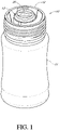
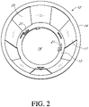
- Figures 1 to 3 illustrate a dispensing device 10 according to an example, which does not form part of the invention, which includes a supporting assembly 12 that engages the bottle 11 and a replaceable cartridge 13 that is seated on the supporting assembly 12.
- the supporting assembly 12 can include an outer annular flange 14 that can be fixed to an upper rim of an opening of the bottle 11 and an inner annular flange 15 that can be connected to the outer annular flange 14 by five bridging members 17 extending between the inner and outer flanges 14 and 15.
- the inner annular flange 15 can be connected to the outer annular flange 14 by a different number of bridging members 17, such as one, two, three, four, five, six, or seven or more bridging members 17. Gaps 35 can exist between the one or more bridging members 17.
- the outer annular flange 14 can be fixed to the upper rim of the bottle 11 using any suitable means including plastics welding or by means of an adhesive.
- the bridging members 17 are configured so as to locate the inner annular flange 15 at a spacing from the opening of the bottle 11.
- the cartridge 13 can include a receptacle shaped body 18 having a cylindrical sidewall defining a circular opening 19 at one end and a top wall including a rotatable dial 20, as illustrated in Figure 1 .
- an opening mechanism (not shown in Figures 1 to 3 ) that is operated by the rotatable dial 20 can be preinstalled into the receptacle body 18, and the formulation can be loaded into the receptacle body 18.
- a sealing membrane 50 can be fixed to the opening 19 to form a sealed chamber containing a known quantity of the formulation and the opening mechanism.
- the opening mechanism can include a first screw thread that cooperates with a second screw thread on the inside surface of the receptacle body 18, when a user turns the dial 20.
- the second screw thread can cooperate with the first screw thread on the opening mechanism and cause the opening mechanism to open the sealing membrane 50 wherein the formulation in the sealed chamber is released.
- the end of the cartridge 13 having the opening 19 can be seated on the inner annular flange 15 of the supporting assembly 12 so that the cartridge 13 is predominantly accommodated or positioned below the opening of the bottle 11 and can be entirely within the bottle 11 or below the opening of the bottle 11.
- the inner annular flange 15 can be considered as defining a stop preventing the beverage ingredient cartridge 13 from falling into the bottle 11.
- the cartridge 13 and supporting assembly 12 can include cooperating formations.
- the cylindrical sidewall adjacent to the opening 19 of the cartridge 13 includes indentations 9 that can receive projections 21 extending from the inner annular flange 15 of the supporting assembly 12.
- the cartridge 13 can include projections that are received by openings or indentations in the supporting assembly 12.
- the outer annular flange 14 can be fixed to the rim of the bottle 11, for example, by plastics welding or by glue.
- the bottle 11 and the dispensing device 10 can also be fitted with a closure cap that can be screwed onto the bottle 11.
- the closure cap can be any suitable closure, such as a teat cap for feeding a baby, a convention closed end cap, or a sports bottle cap having a push and pull nozzle.
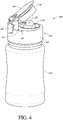
- Figures 4 , 5A and 5B illustrate a dispensing device 10A according to an embodiment which can be fitted to a bottle 11A for treating the contents of the bottle 11A with a formulation.
- the parts, components, and features of the dispensing device 10A that are similar or the same as corresponding parts, components, and features of the dispensing device 10 are identified with the same reference numerals, except that an "A" has been added thereto.
- the dispensing device 10A includes a supporting assembly 12A including an inner body 31 and a cartridge 13A that can contain a formulation.
- the cartridge 13A of this embodiment can be similar to the cartridge 13 used with the previously-discussed embodiment, save for a number of differences the majority of which will now be described.
- the cartridge 13A of this embodiment can include a receptacle body defined by a cylindrical wall 18A having an end with an opening 19A and an opposite top wall 22 having an outer peripheral region 23, a step formation 24 and a button 25 centrally located on the top wall 22 which protrudes above the step formation 24.
- the button 25 is shown in a raised unpressed position in the Figures 4 and 5A .
- the cartridge 13A also can include an opening mechanism 26 that can be located inside the cartridge 13A during the manufacturing or filling process and during the dispensing process.
- the opening mechanism 26 can have a head 27 which engages on inside face of the button 25, a leg 28 extending from the head 27, and a foot portion 29 arranged to extend about part of the inner circumference of the cartridge 13A.
- the leg 28 can have an L-shape (see Figure 5A ).
- the foot portion 29 can have curved sides that complement the circumference of the cartridge 13A which converge to form a centralized point 30 on a loading bearing edge of the foot portion 29.
- a sealing membrane 50 can be adhered or welded to the open end 19A of the receptacle to form a sealed chamber containing the formulation and the opening mechanism 26.
- the head 27, leg 28, and foot portion 29 of the opening mechanism 26 can be sized such that the head 27 engages the button 25 of the cartridge 13A when the button 25 is in the raised position, and a user on the pressing the button 25 can cause the opening mechanism 26 to be advanced toward the sealing membrane 50, and break the membrane 50 so as to discharge the formulation.
- the inner body 31 of the supporting assembly 12A of the an embodiment includes an outer annular flange 14A, for engaging the opening of the bottle, and an inner flange 15A that defines an inner aperture 16A.
- the inner aperture 16A can be sized to receive the cylindrical sidewall 18A of the cartridge 13A, as shown in Figure 5B .
- the outer flange 14A and the inner flange 15A can be interconnected by one or more bridging members 17A having a first limb 33 extending downward and a second limb 34 extending inwardly.
- the outer flange 14A and the inner flange 15A can be interconnected by one, two, three, four, five, six, seven, or eight or more bridging members 17A having a first limb 33 extending downward and a second limb 34 extending inwardly.
- the bridging members 17A can be L-shaped.
- the bridging members 17A can be spaced from each other by gaps 35A.
- a user can position the cartridge 13A in the opening 16A of the supporting assembly 12A with an outer lip formation 32 of the cartridge 13A being seated on the inner flange 15A of the supporting assembly 12A.
- the outer flange 14A of the inner body 31 can be seated on an opening of the bottle 11A, the cartridge 13A being received by the inner body 31, and dispensing device 10A also including a removable closure cap 40 being fitted over the inner body 31.
- the closure cap 40 can have a top wall which can also be considered to be a "top surface” 41 and an outer skirt 42 which can also be considered to be an "outer wall” 42 extending from the top wall 41, the outer skirt 42 can have an inwardly facing screw thread for cooperating with the thread on the neck of the bottle 11A.
- the top wall 41 can have an aperture that aligns with the press button 25 of the cartridge 13A.
- the aperture in the top wall 41 of the closure cap 40 can be sized to allow the cartridge 13A to pass through the aperture to allow the cartridge 13A to be replaced with a fresh cartridge as desired.
- the top wall 41 of the closure cap 40 can include a collar 43 extending upwardly from the aperture and around a perimeter of the aperture.
- the closure cap 40 can include a pivoting lever 44 which can be pressed by a user so as to engage and press the press button 25 of the cartridge 13A and break the seal of the sealing membrane 50.
- the inside face of the pivoting lever which can be considered to be a "cover” or “lid” 44, can include a skirt 45 extending around a perimeter of the pivoting lever 44 that can make a sealing engagement with the collar 43 extending from the top wall 41 of the closure cap 40 to allow the bottle 11A to be inverted during consumption without leakage through the aperture in the top wall 41.
- a lower end of the skirt 45 of the pivoting lever 44 can further press the outer peripheral region 23 of the top wall 22 of the cartridge 13A onto the inner annular flange 15A of the inner body 31 of the supporting assembly 12A, thereby further sealing the contents of the bottle 11A when the pivoting lever 44 is pressed.
- the closure cap 40 can include a nozzle, which can also be considered to be a "drink through valve” 46 having a push pull closure to allow a user to consume the contents of the bottle 11A.
- the drink through valve 46 can include a stem and a valve member movably mounted to the stem between opened and closed positions.
- the stem of the drink through valve 46 can include a passage extending through the top wall 41 and a valve opening, wherein the valve member closes the valve opening when in the closed position and is spaced from the passage when in the open position.
- the stem and valve member of the drink through valve 46 can define a push pull closure to allow contents from the beverage container to pass through the drink through valve 46 when the push pull closure is in the open position and prevent contents from the beverage container from passing through the drink through valve 46 when the push pull closure is in the closed position.
- the drink through valve 46 can be positioned on the top wall which can also be considered to be a "top surface" 41 of the closure cap 40 spaced from the aperture on the top wall 41.
- the gaps 35A between the one or more bridging members 17A allow the contents of the bottle 11A to flow into and through the nozzle 46.
- the 2. dispensing device 10A can include a removable closure cap 40 that comprises a unitary structure with the supporting assembly 12A and/or the inner body 31.
- the removable closure cap 40 can accommodate and or secure the cartridge 13A and position the cartridge 13A, when placed within the aperture in the top wall 41, to allow ingredients from within the cartridge 13A to flow into the bottle 11A.
- the dispensing device 10A can include a top wall 41, a cartridge receptacle for containing a cartridge 13A, a nozzle 46, and a pivoting lever 44.
- the cartridge receptacle can comprise an upper end near the top wall 41 including a first aperture having a perimeter and being located on the top wall 41, a lower end including a second aperture, and an interior sidewall defining an internal volume between the upper and lower ends that can accommodate and/or secure the cartridge 13A.
- the cartridge receptacle can include an inner flange 15A positioned at the lower end and proximate to the second aperture.
- the inner flange 15A as shown in Figure 5B , can define a stop preventing the cartridge 13A from falling through the lower end of the cartridge receptacle into an internal volume of the bottle 11A.
- the internal sidewall of the cartridge receptacle can be cylindrical and thus sized to accommodate a cylindrical beverage ingredient cartridge (see Figure 4 ).
- the lower end of the cartridge receptacle can be configured to allow a beverage ingredient or formulation in the cartridge 13A to flow through the second aperture and into the bottle 11A.
- the nozzle 46 has a push pull closure to allow a user to consume the contents of the bottle 11A.
- the nozzle 46 can include a stem and a valve member movably mounted to the stem between opened and closed positions.
- the stem of the drink through valve 46 can include a passage extending through the top wall 41 and a valve opening, wherein the valve member closes the valve opening when in the closed position and is spaced from the passage when in the open position.
- the stem and valve member of the drink through valve 46 can define a push pull closure to allow contents from the beverage container to pass through the drink through valve 46 when the push pull closure is in the open position and prevent contents from the beverage container from passing through the drink through valve 46 when the push pull closure is in the closed position.
- the drink through valve 46 can be positioned on the top wall 41 of the closure cap 40 spaced from the aperture on the top wall 41.
- the pivoting lever 44 is configured to pivot between open and closed positions and can include a skirt 45 extending around a perimeter of the pivoting lever 44.
- the skirt 45 can form a sealing engagement with a collar 43 extending from the top wall 41 of the closure cap 40 to allow the bottle 11A to be inverted during consumption without leakage through the aperture in the top wall 41.
- the pivoting lever 44 can be pivotably mounted to the top wall 41 at a connection location and the drink through valve 46 can be positioned closer to the aperture in the top wall 41 than to the connection location. Alternatively, the drink through valve 46 can be positioned close to the connection location than to the aperture in the top wall 41.
- the dispensing device 10A includes an outer skirt which can be considered to be an "outer wall" 42 that can have an inwardly facing surface with a screw thread for cooperating with the screw thread of a bottle 11A.
- the inwardly facing surface of the outer skirt 42 can be configured to engage a top portion of a bottle 11A with other securement or sealing methods or structures.
- the outer skirt 42 of the dispensing device 10A can comprise different shapes.
- the outer skirt 42 can be cylindrical.
- the outer skirt 42 extending downwardly from the top wall 41 of the dispensing device 10A and the top portion of the bottle 11A can be cylindrical.
- the cartridge receptacle can be configured to accommodate and/or secure a beverage ingredient cartridge 13A that comprises a cartridge body 18A defining an internal volume (see, e.g., Figure 3 ), a cartridge opening 19A, and a frangible sealing membrane 50 that covers the cartridge opening 19A and seals the internal volume defined by the cartridge body 18A.
- the internal volume defined by the cartridge body 18A can include up to 40 grams of formulation, for example, in the range of 20 to 30 grams of formulation.
- the cartridge 13A can be removable from the cartridge receptacle of the removable closure cap 40.
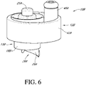
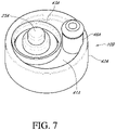
- Figures 6 and 7 illustrate a dispensing device 10B according to example, which does not form part of the invention, which can be fitted to a bottle for treating the contents of a bottle (not shown in Figures 6 or 7 ) with a formulation.
- the parts, components, and features of the dispensing device 10B that are similar or the same as corresponding parts, components, and features of the dispensing device 10 are identified with the same reference numerals, except that a "B" has been added thereto.
- the example shown in Figures 6 and 7 comprises the supporting assembly 12B and cartridge 13B being a unitary structure which requires the device 10B to be a one-use-only device.
- the dispensing device 10B shown in Figures 6 and 7 includes a supporting assembly that engages the neck of a bottle and is fixedly interconnected to the cartridge 13B, for example, by means of integral molding or the cartridge 13B being plastics welded to the supporting assembly 12B.
- the cartridge 13B of this example is similar to the cartridge used with the previous embodiment, save for the cartridge 13B of this example being fixedly connected to the supporting assembly 12B.
- the cartridge 13B can also loaded with the desired formulation to be dispensed by the dispensing device 10B.
- the supporting assembly 12B of this example can include a top wall 41A and an outer skirt 42A extending from the top wall 41A about an outer perimeter of the top wall 41A, and an inner skirt formation 18B extending from the top wall 41A at a spacing from the outer skirt 42A.
- the outer skirt 42A can have an inwardly facing surface with a screw thread for cooperating with the screw thread of a bottle 11 or 11A.
- the inwardly facing surface of the outer skirt 42A can be configured to engage a top portion of a bottle with other securement or sealing methods or structures.
- the outer skirt 42A of the dispensing device 10B can comprise different shapes.
- the outer skirt 42A can be cylindrical.
- the outer skirt 42A extending downwardly from the top wall 41A of the dispensing device 10B and the top portion of the beverage container can be cylindrical.
- the inner skirt formation 18B can be positioned asymmetrically on the top wall 41A and together with the top wall 41A defines a receptacle body for receiving the formulation and an opening mechanism 26A.
- a press button 25A can be located in the top wall 41A of the receptacle body which a user can press to operate the opening mechanism 26A.
- the opening mechanism 26A of this example can be the same as the opening mechanism 26 of the previously-discussed embodiments (shown in Figure 5A ).
- the opening mechanism 26A can have a head 27 which engages on inner surface of the button 25, a leg 28 extending from the head 27, and a foot portion 29A arranged to extend about part of the inner circumference of the cartridge 13B.
- the head 27, leg 28 and foot portion 29A of the opening mechanism 26 can be sized such that the head 27 engages the button 25A of the cartridge 13B when the button 25A is in the raised position, and a user on upon pressing the button 25A can cause the opening mechanism 26A to be advanced toward a sealing membrane 50.
- the sealing membrane can be adhered or welded to the open end of the inner skirt formation 18B to form a sealed chamber containing the formulation and the opening mechanism 26A.
- a lower end of the button 25A can slidably engage to an inside surface of the top wall 41A of the supporting assembly and can form a liquid seal therewith.
- the lower end of the button 25A can include an O-ring that sealingly engages the inside of the top wall 41A when the button 25A is in an operating position.
- the device 10B can include a nozzle 46A having a push pull closure to allow a user to consume the contents of the bottle.
- the drink through valve 46A can be similar to that those in previously-described embodiments.
- the nozzle 46A can open directly into the neck of the bottle 11 or 11A and allow the contents of the bottle 11 or 11A to be consumed.
- the outer skirt of the dispensing device shown in Figures 4 , 6 and 7 can include a tamper evidence band which is frangibly connected to a lower end of the outer skirt which is retained on the bottle when the dispensing device is removed from the bottle.
Landscapes
- Engineering & Computer Science (AREA)
- Mechanical Engineering (AREA)
- Health & Medical Sciences (AREA)
- Life Sciences & Earth Sciences (AREA)
- Animal Behavior & Ethology (AREA)
- General Health & Medical Sciences (AREA)
- Public Health (AREA)
- Veterinary Medicine (AREA)
- Closures For Containers (AREA)
Claims (2)
- Getränkebehälter und Ausgabevorrichtung (10), umfassend:einen Getränkebehälter (11), der einen Körper (18) und einen oberen Abschnitt (11A) mit einer ersten Öffnung aufweist, die ein erstes Innenvolumen definiert, wobei der Getränkebehälter (11) konfiguriert ist, um ein flüssiges Getränk zu enthalten;eine abnehmbare Deckelanordnung (40), die konfiguriert ist, um am oberen Abschnitt (11A) des Getränkebehälters und über der ersten Öffnung befestigt zu werden, wobei die abnehmbare Deckelanordnung (40) umfasst:eine obere Fläche (41);eine Kartuschenaufnahme, die ein unteres Ende umfasst, das eine zweite Öffnung enthält, und einer zylindrischen Seitenwand, die ein zweites Innenvolumen zwischen dem oberen und dem unteren Ende definiert, wobei die Kartuschenaufnahme ferner einen inneren Flansch (15A) umfasst, der am unteren Ende und in der Nähe der zweiten Öffnung positioniert ist;eine Außenwand (42), die sich von der oberen Fläche (41) nach unten erstreckt und eine nach innen weisende Fläche umfasst, die konfiguriert ist, um mit dem oberen Abschnitt (11A) des Getränkebehälters in Eingriff zu kommen;ein Trinkventil (46), das einen Schaft und ein Ventilelement umfasst, das zwischen einer geöffneten und einer geschlossenen Position beweglich an dem Schaft montiert ist, wobei der Schaft einen Durchgang umfasst, der sich durch die obere Oberfläche (41) erstreckt, und eine zweite Öffnung, wobei das Ventilelement die zweite Öffnung verschließt, wenn es sich in der geschlossenen Position befindet, und von dem Durchgang beabstandet ist, wenn es sich in der offenen Position befindet, wobei der Schaft und das Ventilelement einen Push-Pull-Verschluss definieren, um Inhalt aus dem Getränkebehälter durch das Trinkventil (46) passieren zu lassen, wenn sich der Push-Pull-Verschluss in der offenen Position befindet, und verhindern, dass Inhalte aus dem Getränkebehälter durch das Trinkventil (46) gelangen, wenn sich der Push-Pull-Verschluss in der geschlossenen Position befindet, wobei das Trinkventil (46) auf der oberen Fläche (41) der abnehmbaren Deckelanordnung (44) im Abstand von der ersten Öffnung auf der oberen Fläche (41) angeordnet ist; undeine Deckung (44)dadurch gekennzeichnet,dass die Kartuschenaufnahme ein oberes Ende umfasst, das eine erste Öffnung umfasst, die einen Umfang aufweist und sich auf der oberen Oberfläche (41) befindet;dass der Getränkebehälter und die Ausgabevorrichtung (10) ferner eine Getränkebestandteilkartusche umfassen, die einen Kartuschenkörper (18A), der ein drittes Innenvolumen definiert, eine Kartuschenöffnung (19A) und eine zerbrechliche Dichtungsmembran (50) umfasst, die die Kartuschenöffnung bedeckt und das durch den Kartuschenkörper (18A) definierte dritte Innenvolumen abdichtet, wobei das dritte Innenvolumen eine Formulierung von Getränkebestandteilen enthält, die mit flüssigen Inhalten des Getränkebehälters mischbar ist;
wobei das zweite Innenvolumen und die erste Öffnung so bemessen sind, dass die Getränkebestandteilkartusche durch die erste Öffnung und in das zweite Innenvolumen eingeführt werden kann, wobei die Kartuschenaufnahme so konfiguriert ist, dass einen Getränkebestandteil in der Getränkebestandteilkartusche durch die zweite Öffnung und in den Getränkebehälter fließen kann, wobei der innere Flansch (15A) einen Anschlag definiert, der verhindert, dass die Getränkebestandteilkartusche durch das untere Ende der Kartuschenaufnahme in das erste Innenvolumen des Getränkebehälters fällt; undeinen Kragen (43), der sich von der oberen Fläche (41) nach oben und um den Umfang der ersten Öffnung des oberen Endes der Kartuschenaufnahme herum erstreckt;dass die Abdeckung (44) schwenkbar an der oberen Oberfläche (41) der abnehmbaren Deckelanordnung montiert ist, die so konfiguriert ist, dass sie zwischen offenen und geschlossenen Positionen schwenkt, wobei die Abdeckung einen Abdeckungsumfang und eine Schürze (45) umfasst, die sich um den Abdeckungsumfang erstreckt, wobei, wenn sich die Abdeckung in der geschlossenen Position befindet, die Abdeckung die erste Öffnung auf der oberen Fläche (41) abdeckt und die Schürze konfiguriert ist, um mit dem Kragen (43) auf der oberen Fläche (41) in Eingriff zu kommen und einen abdichtenden Eingriff bildet, der es ermöglicht, dass der Getränkebehälter (11) während des Konsums umgekehrt wird, ohne durch die erste Öffnung zu lecken. - Getränkebehälter und Ausgabevorrichtung (10) nach Anspruch 1, wobei die Kartusche von der Deckelanordnung (40) entfernbar ist.
Applications Claiming Priority (2)
| Application Number | Priority Date | Filing Date | Title |
|---|---|---|---|
| AU2016905316A AU2016905316A0 (en) | 2016-12-22 | Device for a drink bottle | |
| PCT/US2017/067747 WO2018119158A1 (en) | 2016-12-22 | 2017-12-20 | Dispensing device for a drink bottle |
Publications (3)
| Publication Number | Publication Date |
|---|---|
| EP3558838A1 EP3558838A1 (de) | 2019-10-30 |
| EP3558838A4 EP3558838A4 (de) | 2020-07-22 |
| EP3558838B1 true EP3558838B1 (de) | 2022-08-10 |
Family
ID=62625781
Family Applications (1)
| Application Number | Title | Priority Date | Filing Date |
|---|---|---|---|
| EP17882357.1A Active EP3558838B1 (de) | 2016-12-22 | 2017-12-20 | Ausgabevorrichtung für eine trinkflasche |
Country Status (6)
| Country | Link |
|---|---|
| US (3) | US10189617B2 (de) |
| EP (1) | EP3558838B1 (de) |
| CN (1) | CN110325450B (de) |
| AU (1) | AU2017379010B2 (de) |
| BR (1) | BR112019013009A2 (de) |
| WO (1) | WO2018119158A1 (de) |
Families Citing this family (4)
| Publication number | Priority date | Publication date | Assignee | Title |
|---|---|---|---|---|
| AU2017379010B2 (en) | 2016-12-22 | 2022-12-08 | Dispensa Holdings Llc | Dispensing device for a drink bottle |
| JP6562987B2 (ja) * | 2017-10-27 | 2019-08-21 | タケヤ化学工業株式会社 | 携帯用飲料容器 |
| US11458443B2 (en) * | 2018-01-23 | 2022-10-04 | Infuze, Llc | Water bottle device assembly |
| US12496257B2 (en) | 2021-09-21 | 2025-12-16 | Dispensa Holdings Llc | Ingredient dispensing and drink through device for beverage container |
Family Cites Families (20)
| Publication number | Priority date | Publication date | Assignee | Title |
|---|---|---|---|---|
| CN2178229Y (zh) * | 1993-10-18 | 1994-09-28 | 黄文田 | 饮料瓶的盖体 |
| CN1222475A (zh) * | 1998-01-05 | 1999-07-14 | 乐博美有限公司 | 饮料容器的盖子 |
| US6003728A (en) * | 1998-10-22 | 1999-12-21 | Aptargroup, Inc. | Dispensing structure with an openable member for separating two products |
| WO2003013962A1 (en) | 2001-08-06 | 2003-02-20 | Sji Limited | A cap |
| US6959839B2 (en) * | 2003-02-10 | 2005-11-01 | Donna Roth | Flavoring component holding dispenser for use with consumable beverages |
| JP4839227B2 (ja) * | 2004-02-19 | 2011-12-21 | ミン リー、ジュン | 貯蔵空間を有するパウチ容器用キャップ |
| AU2005274936B8 (en) * | 2004-07-16 | 2011-04-21 | Closure Systems International, Inc | Tamper-indicating dispensing closure |
| ES2340413T3 (es) * | 2005-04-14 | 2010-06-02 | Medisize Schweiz Ag | Cierre de botella o recipiente para añadir un componente a su contenido. |
| US20080202951A1 (en) * | 2007-02-27 | 2008-08-28 | Mark William Landolt | Dispensing closure for a liquid container |
| US8286812B2 (en) * | 2008-04-11 | 2012-10-16 | Andrzej Buczkowski | Device and method for irreversibly selecting indicia |
| US8230777B2 (en) * | 2008-07-21 | 2012-07-31 | Nutra-Life, Inc. | Water container cap for holding additives to water |
| AU2009346262B2 (en) | 2009-05-15 | 2016-06-09 | Click Cap Tech Sdn. Bhd. | Dispensing closure for container |
| US8684231B2 (en) * | 2009-10-15 | 2014-04-01 | Thermos L.L.C. | Drink additive delivery lid system |
| WO2011098865A1 (en) * | 2010-02-12 | 2011-08-18 | Raoul Eugenio Fontana | A container closure |
| US9242773B1 (en) * | 2011-05-27 | 2016-01-26 | Michael R. Anderson | Dispensing capsule with button blast and drinking feature |
| US20150166239A1 (en) | 2012-05-15 | 2015-06-18 | Ahhmigo | Cap device and methods |
| KR20130128753A (ko) * | 2012-05-18 | 2013-11-27 | 이성재 | 밀폐마개를 갖는 이종물질 수용장치 |
| KR101401005B1 (ko) | 2014-01-22 | 2014-05-29 | 동아정밀공업(주) | 기능성 첨가제가 내장된 식음료용 용기캡 |
| TW201538398A (zh) | 2014-04-02 | 2015-10-16 | Crown Mfg Corp | 飲料用容器之栓體 |
| AU2017379010B2 (en) | 2016-12-22 | 2022-12-08 | Dispensa Holdings Llc | Dispensing device for a drink bottle |
-
2017
- 2017-12-20 AU AU2017379010A patent/AU2017379010B2/en active Active
- 2017-12-20 CN CN201780086807.3A patent/CN110325450B/zh active Active
- 2017-12-20 EP EP17882357.1A patent/EP3558838B1/de active Active
- 2017-12-20 BR BR112019013009-8A patent/BR112019013009A2/pt not_active Application Discontinuation
- 2017-12-20 WO PCT/US2017/067747 patent/WO2018119158A1/en not_active Ceased
- 2017-12-20 US US15/849,500 patent/US10189617B2/en active Active
-
2018
- 2018-10-10 US US16/156,891 patent/US20190039793A1/en not_active Abandoned
-
2020
- 2020-05-20 US US16/879,574 patent/US11203472B2/en active Active
Also Published As
| Publication number | Publication date |
|---|---|
| WO2018119158A1 (en) | 2018-06-28 |
| US11203472B2 (en) | 2021-12-21 |
| US10189617B2 (en) | 2019-01-29 |
| BR112019013009A2 (pt) | 2020-03-10 |
| AU2017379010A1 (en) | 2019-07-18 |
| CN110325450B (zh) | 2021-06-18 |
| AU2017379010B2 (en) | 2022-12-08 |
| US20190039793A1 (en) | 2019-02-07 |
| CN110325450A (zh) | 2019-10-11 |
| CA3048207A1 (en) | 2018-06-28 |
| EP3558838A4 (de) | 2020-07-22 |
| US20210101726A1 (en) | 2021-04-08 |
| EP3558838A1 (de) | 2019-10-30 |
| US20180178958A1 (en) | 2018-06-28 |
Similar Documents
| Publication | Publication Date | Title |
|---|---|---|
| US11203472B2 (en) | Dispensing device for a drink bottle | |
| AU762110B2 (en) | Discharge cap for releasable tablet | |
| CA2679472C (en) | Ingredient release spout | |
| EP1023229B1 (de) | Ausgabeverschluss mit einer eine tablette enthaltenden durchdrückpackung | |
| US8485353B2 (en) | Cap assembly having storage chamber for secondary material with inseparable working member | |
| US9592940B2 (en) | Ingredient release spout | |
| US20150166239A1 (en) | Cap device and methods | |
| US20100288767A1 (en) | Fillable closure device with triggering pushbutton | |
| US20100044254A1 (en) | Beverage mix dispensing closure | |
| JP2007505009A (ja) | 分配蓋体 | |
| US20050279653A1 (en) | Device for dispensing material into a container | |
| NZ233461A (en) | Drink carton container with piercer and drinking spout | |
| MX2010004472A (es) | Tapa de liberacion de concentrado. | |
| KR20090110695A (ko) | 혼합원료 캡슐이 구비된 음료용기 | |
| AU2007224391A1 (en) | Tamper resistant closures | |
| EP1727739B1 (de) | Volumetrischer spender | |
| WO2008002160A2 (en) | Cap with a capsule rupturable by a cutter | |
| MXPA06008076A (es) | Capsula que incorpora un dosificador y capa de seguridad que se puede abrir, en particular para envases de dosis individuales. | |
| CA3048207C (en) | Dispensing device for a drink bottle | |
| US20060175330A1 (en) | Enhanced liquid container | |
| WO2006062418A1 (en) | Cartridge for a container | |
| JP4868401B2 (ja) | 飲料容器 | |
| WO2013173470A1 (en) | Cap device and methods | |
| KR20050109017A (ko) | 내용물이 저장되는 용기 뚜껑 |
Legal Events
| Date | Code | Title | Description |
|---|---|---|---|
| STAA | Information on the status of an ep patent application or granted ep patent |
Free format text: STATUS: THE INTERNATIONAL PUBLICATION HAS BEEN MADE |
|
| PUAI | Public reference made under article 153(3) epc to a published international application that has entered the european phase |
Free format text: ORIGINAL CODE: 0009012 |
|
| STAA | Information on the status of an ep patent application or granted ep patent |
Free format text: STATUS: REQUEST FOR EXAMINATION WAS MADE |
|
| 17P | Request for examination filed |
Effective date: 20190627 |
|
| AK | Designated contracting states |
Kind code of ref document: A1 Designated state(s): AL AT BE BG CH CY CZ DE DK EE ES FI FR GB GR HR HU IE IS IT LI LT LU LV MC MK MT NL NO PL PT RO RS SE SI SK SM TR |
|
| AX | Request for extension of the european patent |
Extension state: BA ME |
|
| DAV | Request for validation of the european patent (deleted) | ||
| DAX | Request for extension of the european patent (deleted) | ||
| A4 | Supplementary search report drawn up and despatched |
Effective date: 20200618 |
|
| RIC1 | Information provided on ipc code assigned before grant |
Ipc: B65D 85/72 20060101ALI20200612BHEP Ipc: B65D 51/24 20060101ALI20200612BHEP Ipc: B65D 47/24 20060101ALI20200612BHEP Ipc: B65D 81/34 20060101ALI20200612BHEP Ipc: B65D 51/28 20060101ALI20200612BHEP Ipc: B65D 81/32 20060101ALI20200612BHEP Ipc: B65D 25/08 20060101AFI20200612BHEP |
|
| RAP1 | Party data changed (applicant data changed or rights of an application transferred) |
Owner name: DISPENSA HOLDINGS LLC |
|
| GRAP | Despatch of communication of intention to grant a patent |
Free format text: ORIGINAL CODE: EPIDOSNIGR1 |
|
| STAA | Information on the status of an ep patent application or granted ep patent |
Free format text: STATUS: GRANT OF PATENT IS INTENDED |
|
| INTG | Intention to grant announced |
Effective date: 20211109 |
|
| GRAS | Grant fee paid |
Free format text: ORIGINAL CODE: EPIDOSNIGR3 |
|
| GRAA | (expected) grant |
Free format text: ORIGINAL CODE: 0009210 |
|
| STAA | Information on the status of an ep patent application or granted ep patent |
Free format text: STATUS: THE PATENT HAS BEEN GRANTED |
|
| AK | Designated contracting states |
Kind code of ref document: B1 Designated state(s): AL AT BE BG CH CY CZ DE DK EE ES FI FR GB GR HR HU IE IS IT LI LT LU LV MC MK MT NL NO PL PT RO RS SE SI SK SM TR |
|
| REG | Reference to a national code |
Ref country code: AT Ref legal event code: REF Ref document number: 1510400 Country of ref document: AT Kind code of ref document: T Effective date: 20220815 Ref country code: CH Ref legal event code: EP |
|
| REG | Reference to a national code |
Ref country code: DE Ref legal event code: R096 Ref document number: 602017060614 Country of ref document: DE |
|
| REG | Reference to a national code |
Ref country code: IE Ref legal event code: FG4D |
|
| REG | Reference to a national code |
Ref country code: NL Ref legal event code: MP Effective date: 20220810 |
|
| REG | Reference to a national code |
Ref country code: LT Ref legal event code: MG9D |
|
| PG25 | Lapsed in a contracting state [announced via postgrant information from national office to epo] |
Ref country code: SE Free format text: LAPSE BECAUSE OF FAILURE TO SUBMIT A TRANSLATION OF THE DESCRIPTION OR TO PAY THE FEE WITHIN THE PRESCRIBED TIME-LIMIT Effective date: 20220810 Ref country code: RS Free format text: LAPSE BECAUSE OF FAILURE TO SUBMIT A TRANSLATION OF THE DESCRIPTION OR TO PAY THE FEE WITHIN THE PRESCRIBED TIME-LIMIT Effective date: 20220810 Ref country code: PT Free format text: LAPSE BECAUSE OF FAILURE TO SUBMIT A TRANSLATION OF THE DESCRIPTION OR TO PAY THE FEE WITHIN THE PRESCRIBED TIME-LIMIT Effective date: 20221212 Ref country code: NO Free format text: LAPSE BECAUSE OF FAILURE TO SUBMIT A TRANSLATION OF THE DESCRIPTION OR TO PAY THE FEE WITHIN THE PRESCRIBED TIME-LIMIT Effective date: 20221110 Ref country code: NL Free format text: LAPSE BECAUSE OF FAILURE TO SUBMIT A TRANSLATION OF THE DESCRIPTION OR TO PAY THE FEE WITHIN THE PRESCRIBED TIME-LIMIT Effective date: 20220810 Ref country code: LV Free format text: LAPSE BECAUSE OF FAILURE TO SUBMIT A TRANSLATION OF THE DESCRIPTION OR TO PAY THE FEE WITHIN THE PRESCRIBED TIME-LIMIT Effective date: 20220810 Ref country code: LT Free format text: LAPSE BECAUSE OF FAILURE TO SUBMIT A TRANSLATION OF THE DESCRIPTION OR TO PAY THE FEE WITHIN THE PRESCRIBED TIME-LIMIT Effective date: 20220810 Ref country code: FI Free format text: LAPSE BECAUSE OF FAILURE TO SUBMIT A TRANSLATION OF THE DESCRIPTION OR TO PAY THE FEE WITHIN THE PRESCRIBED TIME-LIMIT Effective date: 20220810 |
|
| REG | Reference to a national code |
Ref country code: AT Ref legal event code: MK05 Ref document number: 1510400 Country of ref document: AT Kind code of ref document: T Effective date: 20220810 |
|
| PG25 | Lapsed in a contracting state [announced via postgrant information from national office to epo] |
Ref country code: PL Free format text: LAPSE BECAUSE OF FAILURE TO SUBMIT A TRANSLATION OF THE DESCRIPTION OR TO PAY THE FEE WITHIN THE PRESCRIBED TIME-LIMIT Effective date: 20220810 Ref country code: IS Free format text: LAPSE BECAUSE OF FAILURE TO SUBMIT A TRANSLATION OF THE DESCRIPTION OR TO PAY THE FEE WITHIN THE PRESCRIBED TIME-LIMIT Effective date: 20221210 Ref country code: HR Free format text: LAPSE BECAUSE OF FAILURE TO SUBMIT A TRANSLATION OF THE DESCRIPTION OR TO PAY THE FEE WITHIN THE PRESCRIBED TIME-LIMIT Effective date: 20220810 Ref country code: GR Free format text: LAPSE BECAUSE OF FAILURE TO SUBMIT A TRANSLATION OF THE DESCRIPTION OR TO PAY THE FEE WITHIN THE PRESCRIBED TIME-LIMIT Effective date: 20221111 |
|
| PG25 | Lapsed in a contracting state [announced via postgrant information from national office to epo] |
Ref country code: SM Free format text: LAPSE BECAUSE OF FAILURE TO SUBMIT A TRANSLATION OF THE DESCRIPTION OR TO PAY THE FEE WITHIN THE PRESCRIBED TIME-LIMIT Effective date: 20220810 Ref country code: RO Free format text: LAPSE BECAUSE OF FAILURE TO SUBMIT A TRANSLATION OF THE DESCRIPTION OR TO PAY THE FEE WITHIN THE PRESCRIBED TIME-LIMIT Effective date: 20220810 Ref country code: ES Free format text: LAPSE BECAUSE OF FAILURE TO SUBMIT A TRANSLATION OF THE DESCRIPTION OR TO PAY THE FEE WITHIN THE PRESCRIBED TIME-LIMIT Effective date: 20220810 Ref country code: DK Free format text: LAPSE BECAUSE OF FAILURE TO SUBMIT A TRANSLATION OF THE DESCRIPTION OR TO PAY THE FEE WITHIN THE PRESCRIBED TIME-LIMIT Effective date: 20220810 Ref country code: CZ Free format text: LAPSE BECAUSE OF FAILURE TO SUBMIT A TRANSLATION OF THE DESCRIPTION OR TO PAY THE FEE WITHIN THE PRESCRIBED TIME-LIMIT Effective date: 20220810 Ref country code: AT Free format text: LAPSE BECAUSE OF FAILURE TO SUBMIT A TRANSLATION OF THE DESCRIPTION OR TO PAY THE FEE WITHIN THE PRESCRIBED TIME-LIMIT Effective date: 20220810 |
|
| REG | Reference to a national code |
Ref country code: DE Ref legal event code: R097 Ref document number: 602017060614 Country of ref document: DE |
|
| PG25 | Lapsed in a contracting state [announced via postgrant information from national office to epo] |
Ref country code: SK Free format text: LAPSE BECAUSE OF FAILURE TO SUBMIT A TRANSLATION OF THE DESCRIPTION OR TO PAY THE FEE WITHIN THE PRESCRIBED TIME-LIMIT Effective date: 20220810 Ref country code: EE Free format text: LAPSE BECAUSE OF FAILURE TO SUBMIT A TRANSLATION OF THE DESCRIPTION OR TO PAY THE FEE WITHIN THE PRESCRIBED TIME-LIMIT Effective date: 20220810 |
|
| PLBE | No opposition filed within time limit |
Free format text: ORIGINAL CODE: 0009261 |
|
| STAA | Information on the status of an ep patent application or granted ep patent |
Free format text: STATUS: NO OPPOSITION FILED WITHIN TIME LIMIT |
|
| PG25 | Lapsed in a contracting state [announced via postgrant information from national office to epo] |
Ref country code: AL Free format text: LAPSE BECAUSE OF FAILURE TO SUBMIT A TRANSLATION OF THE DESCRIPTION OR TO PAY THE FEE WITHIN THE PRESCRIBED TIME-LIMIT Effective date: 20220810 |
|
| 26N | No opposition filed |
Effective date: 20230511 |
|
| REG | Reference to a national code |
Ref country code: CH Ref legal event code: PL |
|
| REG | Reference to a national code |
Ref country code: BE Ref legal event code: MM Effective date: 20221231 |
|
| PG25 | Lapsed in a contracting state [announced via postgrant information from national office to epo] |
Ref country code: SI Free format text: LAPSE BECAUSE OF FAILURE TO SUBMIT A TRANSLATION OF THE DESCRIPTION OR TO PAY THE FEE WITHIN THE PRESCRIBED TIME-LIMIT Effective date: 20220810 Ref country code: LU Free format text: LAPSE BECAUSE OF NON-PAYMENT OF DUE FEES Effective date: 20221220 |
|
| PG25 | Lapsed in a contracting state [announced via postgrant information from national office to epo] |
Ref country code: LI Free format text: LAPSE BECAUSE OF NON-PAYMENT OF DUE FEES Effective date: 20221231 Ref country code: IE Free format text: LAPSE BECAUSE OF NON-PAYMENT OF DUE FEES Effective date: 20221220 Ref country code: CH Free format text: LAPSE BECAUSE OF NON-PAYMENT OF DUE FEES Effective date: 20221231 |
|
| PG25 | Lapsed in a contracting state [announced via postgrant information from national office to epo] |
Ref country code: BE Free format text: LAPSE BECAUSE OF NON-PAYMENT OF DUE FEES Effective date: 20221231 |
|
| PG25 | Lapsed in a contracting state [announced via postgrant information from national office to epo] |
Ref country code: HU Free format text: LAPSE BECAUSE OF FAILURE TO SUBMIT A TRANSLATION OF THE DESCRIPTION OR TO PAY THE FEE WITHIN THE PRESCRIBED TIME-LIMIT; INVALID AB INITIO Effective date: 20171220 |
|
| PG25 | Lapsed in a contracting state [announced via postgrant information from national office to epo] |
Ref country code: CY Free format text: LAPSE BECAUSE OF FAILURE TO SUBMIT A TRANSLATION OF THE DESCRIPTION OR TO PAY THE FEE WITHIN THE PRESCRIBED TIME-LIMIT Effective date: 20220810 |
|
| PG25 | Lapsed in a contracting state [announced via postgrant information from national office to epo] |
Ref country code: MK Free format text: LAPSE BECAUSE OF FAILURE TO SUBMIT A TRANSLATION OF THE DESCRIPTION OR TO PAY THE FEE WITHIN THE PRESCRIBED TIME-LIMIT Effective date: 20220810 Ref country code: IT Free format text: LAPSE BECAUSE OF FAILURE TO SUBMIT A TRANSLATION OF THE DESCRIPTION OR TO PAY THE FEE WITHIN THE PRESCRIBED TIME-LIMIT Effective date: 20220810 |
|
| PG25 | Lapsed in a contracting state [announced via postgrant information from national office to epo] |
Ref country code: MC Free format text: LAPSE BECAUSE OF FAILURE TO SUBMIT A TRANSLATION OF THE DESCRIPTION OR TO PAY THE FEE WITHIN THE PRESCRIBED TIME-LIMIT Effective date: 20220810 |
|
| PG25 | Lapsed in a contracting state [announced via postgrant information from national office to epo] |
Ref country code: TR Free format text: LAPSE BECAUSE OF FAILURE TO SUBMIT A TRANSLATION OF THE DESCRIPTION OR TO PAY THE FEE WITHIN THE PRESCRIBED TIME-LIMIT Effective date: 20220810 Ref country code: MC Free format text: LAPSE BECAUSE OF FAILURE TO SUBMIT A TRANSLATION OF THE DESCRIPTION OR TO PAY THE FEE WITHIN THE PRESCRIBED TIME-LIMIT Effective date: 20220810 |
|
| PG25 | Lapsed in a contracting state [announced via postgrant information from national office to epo] |
Ref country code: BG Free format text: LAPSE BECAUSE OF FAILURE TO SUBMIT A TRANSLATION OF THE DESCRIPTION OR TO PAY THE FEE WITHIN THE PRESCRIBED TIME-LIMIT Effective date: 20220810 |
|
| PG25 | Lapsed in a contracting state [announced via postgrant information from national office to epo] |
Ref country code: MT Free format text: LAPSE BECAUSE OF FAILURE TO SUBMIT A TRANSLATION OF THE DESCRIPTION OR TO PAY THE FEE WITHIN THE PRESCRIBED TIME-LIMIT Effective date: 20220810 |
|
| PGFP | Annual fee paid to national office [announced via postgrant information from national office to epo] |
Ref country code: DE Payment date: 20241220 Year of fee payment: 8 |
|
| PGFP | Annual fee paid to national office [announced via postgrant information from national office to epo] |
Ref country code: GB Payment date: 20241217 Year of fee payment: 8 |
|
| PGFP | Annual fee paid to national office [announced via postgrant information from national office to epo] |
Ref country code: FR Payment date: 20241217 Year of fee payment: 8 |