EP3558735B1 - Clamp-based fixation of battery module compartment cover - Google Patents
Clamp-based fixation of battery module compartment cover Download PDFInfo
- Publication number
- EP3558735B1 EP3558735B1 EP18795890.5A EP18795890A EP3558735B1 EP 3558735 B1 EP3558735 B1 EP 3558735B1 EP 18795890 A EP18795890 A EP 18795890A EP 3558735 B1 EP3558735 B1 EP 3558735B1
- Authority
- EP
- European Patent Office
- Prior art keywords
- battery module
- compartment
- endplate
- section
- clamping bar
- Prior art date
- Legal status (The legal status is an assumption and is not a legal conclusion. Google has not performed a legal analysis and makes no representation as to the accuracy of the status listed.)
- Active
Links
Images





Classifications
-
- B—PERFORMING OPERATIONS; TRANSPORTING
- B60—VEHICLES IN GENERAL
- B60K—ARRANGEMENT OR MOUNTING OF PROPULSION UNITS OR OF TRANSMISSIONS IN VEHICLES; ARRANGEMENT OR MOUNTING OF PLURAL DIVERSE PRIME-MOVERS IN VEHICLES; AUXILIARY DRIVES FOR VEHICLES; INSTRUMENTATION OR DASHBOARDS FOR VEHICLES; ARRANGEMENTS IN CONNECTION WITH COOLING, AIR INTAKE, GAS EXHAUST OR FUEL SUPPLY OF PROPULSION UNITS IN VEHICLES
- B60K1/00—Arrangement or mounting of electrical propulsion units
- B60K1/04—Arrangement or mounting of electrical propulsion units of the electric storage means for propulsion
-
- H—ELECTRICITY
- H01—ELECTRIC ELEMENTS
- H01M—PROCESSES OR MEANS, e.g. BATTERIES, FOR THE DIRECT CONVERSION OF CHEMICAL ENERGY INTO ELECTRICAL ENERGY
- H01M10/00—Secondary cells; Manufacture thereof
- H01M10/60—Heating or cooling; Temperature control
- H01M10/65—Means for temperature control structurally associated with the cells
- H01M10/655—Solid structures for heat exchange or heat conduction
- H01M10/6556—Solid parts with flow channel passages or pipes for heat exchange
-
- H—ELECTRICITY
- H01—ELECTRIC ELEMENTS
- H01M—PROCESSES OR MEANS, e.g. BATTERIES, FOR THE DIRECT CONVERSION OF CHEMICAL ENERGY INTO ELECTRICAL ENERGY
- H01M50/00—Constructional details or processes of manufacture of the non-active parts of electrochemical cells other than fuel cells, e.g. hybrid cells
- H01M50/20—Mountings; Secondary casings or frames; Racks, modules or packs; Suspension devices; Shock absorbers; Transport or carrying devices; Holders
- H01M50/204—Racks, modules or packs for multiple batteries or multiple cells
-
- H—ELECTRICITY
- H01—ELECTRIC ELEMENTS
- H01M—PROCESSES OR MEANS, e.g. BATTERIES, FOR THE DIRECT CONVERSION OF CHEMICAL ENERGY INTO ELECTRICAL ENERGY
- H01M50/00—Constructional details or processes of manufacture of the non-active parts of electrochemical cells other than fuel cells, e.g. hybrid cells
- H01M50/20—Mountings; Secondary casings or frames; Racks, modules or packs; Suspension devices; Shock absorbers; Transport or carrying devices; Holders
- H01M50/262—Mountings; Secondary casings or frames; Racks, modules or packs; Suspension devices; Shock absorbers; Transport or carrying devices; Holders with fastening means, e.g. locks
-
- H—ELECTRICITY
- H01—ELECTRIC ELEMENTS
- H01M—PROCESSES OR MEANS, e.g. BATTERIES, FOR THE DIRECT CONVERSION OF CHEMICAL ENERGY INTO ELECTRICAL ENERGY
- H01M50/00—Constructional details or processes of manufacture of the non-active parts of electrochemical cells other than fuel cells, e.g. hybrid cells
- H01M50/20—Mountings; Secondary casings or frames; Racks, modules or packs; Suspension devices; Shock absorbers; Transport or carrying devices; Holders
- H01M50/271—Lids or covers for the racks or secondary casings
-
- H—ELECTRICITY
- H01—ELECTRIC ELEMENTS
- H01M—PROCESSES OR MEANS, e.g. BATTERIES, FOR THE DIRECT CONVERSION OF CHEMICAL ENERGY INTO ELECTRICAL ENERGY
- H01M50/00—Constructional details or processes of manufacture of the non-active parts of electrochemical cells other than fuel cells, e.g. hybrid cells
- H01M50/30—Arrangements for facilitating escape of gases
- H01M50/317—Re-sealable arrangements
-
- B—PERFORMING OPERATIONS; TRANSPORTING
- B60—VEHICLES IN GENERAL
- B60K—ARRANGEMENT OR MOUNTING OF PROPULSION UNITS OR OF TRANSMISSIONS IN VEHICLES; ARRANGEMENT OR MOUNTING OF PLURAL DIVERSE PRIME-MOVERS IN VEHICLES; AUXILIARY DRIVES FOR VEHICLES; INSTRUMENTATION OR DASHBOARDS FOR VEHICLES; ARRANGEMENTS IN CONNECTION WITH COOLING, AIR INTAKE, GAS EXHAUST OR FUEL SUPPLY OF PROPULSION UNITS IN VEHICLES
- B60K1/00—Arrangement or mounting of electrical propulsion units
- B60K1/04—Arrangement or mounting of electrical propulsion units of the electric storage means for propulsion
- B60K2001/0405—Arrangement or mounting of electrical propulsion units of the electric storage means for propulsion characterised by their position
- B60K2001/0438—Arrangement under the floor
-
- B—PERFORMING OPERATIONS; TRANSPORTING
- B60—VEHICLES IN GENERAL
- B60K—ARRANGEMENT OR MOUNTING OF PROPULSION UNITS OR OF TRANSMISSIONS IN VEHICLES; ARRANGEMENT OR MOUNTING OF PLURAL DIVERSE PRIME-MOVERS IN VEHICLES; AUXILIARY DRIVES FOR VEHICLES; INSTRUMENTATION OR DASHBOARDS FOR VEHICLES; ARRANGEMENTS IN CONNECTION WITH COOLING, AIR INTAKE, GAS EXHAUST OR FUEL SUPPLY OF PROPULSION UNITS IN VEHICLES
- B60K1/00—Arrangement or mounting of electrical propulsion units
- B60K1/04—Arrangement or mounting of electrical propulsion units of the electric storage means for propulsion
- B60K2001/0455—Removal or replacement of the energy storages
- B60K2001/0461—Removal or replacement of the energy storages from the side
-
- B—PERFORMING OPERATIONS; TRANSPORTING
- B60—VEHICLES IN GENERAL
- B60K—ARRANGEMENT OR MOUNTING OF PROPULSION UNITS OR OF TRANSMISSIONS IN VEHICLES; ARRANGEMENT OR MOUNTING OF PLURAL DIVERSE PRIME-MOVERS IN VEHICLES; AUXILIARY DRIVES FOR VEHICLES; INSTRUMENTATION OR DASHBOARDS FOR VEHICLES; ARRANGEMENTS IN CONNECTION WITH COOLING, AIR INTAKE, GAS EXHAUST OR FUEL SUPPLY OF PROPULSION UNITS IN VEHICLES
- B60K1/00—Arrangement or mounting of electrical propulsion units
- B60K1/04—Arrangement or mounting of electrical propulsion units of the electric storage means for propulsion
- B60K2001/0455—Removal or replacement of the energy storages
- B60K2001/0494—Removal or replacement of the energy storages with arrangements for sliding
-
- H—ELECTRICITY
- H01—ELECTRIC ELEMENTS
- H01M—PROCESSES OR MEANS, e.g. BATTERIES, FOR THE DIRECT CONVERSION OF CHEMICAL ENERGY INTO ELECTRICAL ENERGY
- H01M2200/00—Safety devices for primary or secondary batteries
- H01M2200/20—Pressure-sensitive devices
-
- H—ELECTRICITY
- H01—ELECTRIC ELEMENTS
- H01M—PROCESSES OR MEANS, e.g. BATTERIES, FOR THE DIRECT CONVERSION OF CHEMICAL ENERGY INTO ELECTRICAL ENERGY
- H01M2220/00—Batteries for particular applications
- H01M2220/20—Batteries in motive systems, e.g. vehicle, ship, plane
-
- Y—GENERAL TAGGING OF NEW TECHNOLOGICAL DEVELOPMENTS; GENERAL TAGGING OF CROSS-SECTIONAL TECHNOLOGIES SPANNING OVER SEVERAL SECTIONS OF THE IPC; TECHNICAL SUBJECTS COVERED BY FORMER USPC CROSS-REFERENCE ART COLLECTIONS [XRACs] AND DIGESTS
- Y02—TECHNOLOGIES OR APPLICATIONS FOR MITIGATION OR ADAPTATION AGAINST CLIMATE CHANGE
- Y02E—REDUCTION OF GREENHOUSE GAS [GHG] EMISSIONS, RELATED TO ENERGY GENERATION, TRANSMISSION OR DISTRIBUTION
- Y02E60/00—Enabling technologies; Technologies with a potential or indirect contribution to GHG emissions mitigation
- Y02E60/10—Energy storage using batteries
-
- Y—GENERAL TAGGING OF NEW TECHNOLOGICAL DEVELOPMENTS; GENERAL TAGGING OF CROSS-SECTIONAL TECHNOLOGIES SPANNING OVER SEVERAL SECTIONS OF THE IPC; TECHNICAL SUBJECTS COVERED BY FORMER USPC CROSS-REFERENCE ART COLLECTIONS [XRACs] AND DIGESTS
- Y02—TECHNOLOGIES OR APPLICATIONS FOR MITIGATION OR ADAPTATION AGAINST CLIMATE CHANGE
- Y02T—CLIMATE CHANGE MITIGATION TECHNOLOGIES RELATED TO TRANSPORTATION
- Y02T10/00—Road transport of goods or passengers
- Y02T10/60—Other road transportation technologies with climate change mitigation effect
- Y02T10/70—Energy storage systems for electromobility, e.g. batteries
Definitions
- Embodiments relate to clamp-based fixation of a battery module compartment cover.
- Energy storage systems may rely upon batteries for storage of electrical power.
- a battery housing mounted into an electric vehicle houses a plurality of battery cells (e.g., which may be individually mounted into the battery housing, or alternatively may be grouped within respective battery modules that each contain a set of battery cells, with the respective battery modules being mounted into the battery housing).
- battery cells e.g., which may be individually mounted into the battery housing, or alternatively may be grouped within respective battery modules that each contain a set of battery cells, with the respective battery modules being mounted into the battery housing).
- the battery modules in the battery housing are connected in series via busbars to a battery junction box (BJB), and the BJB distributes electric power provided from the busbars to an electric motor that drives the electric vehicle, as well as various other electrical components of the electric vehicle (e.g., a radio, a control console, a vehicle Heating, Ventilation and Air Conditioning (HVAC) system, internal lights, external lights such as head lights and brake lights, etc.).
- HVAC vehicle Heating, Ventilation and Air Conditioning
- EP2722211A1 , WO2018/081650A1 , DE102012217248A1 each disclose battery module arrangements.
- a battery module arrangement is provided according to claim 1.
- Energy storage systems may rely upon batteries for storage of electrical power.
- a battery housing mounted into an electric vehicle houses a plurality of battery cells (e.g., which may be individually mounted into the battery housing, or alternatively may be grouped within respective battery modules that each contain a set of battery cells, with the respective battery modules being mounted into the battery housing).
- battery cells e.g., which may be individually mounted into the battery housing, or alternatively may be grouped within respective battery modules that each contain a set of battery cells, with the respective battery modules being mounted into the battery housing).
- the battery modules in the battery housing are connected in series via busbars to a battery junction box (BJB), and the BJB distributes electric power provided from the busbars to an electric motor that drives the electric vehicle, as well as various other electrical components of the electric vehicle (e.g., a radio, a control console, a vehicle Heating, Ventilation and Air Conditioning (HVAC) system, internal lights, external lights such as head lights and brake lights, etc.).
- HVAC vehicle Heating, Ventilation and Air Conditioning
- FIG. 1 illustrates an isometric front-perspective of an exterior framing of a battery module 100 in accordance with an embodiment of the disclosure.
- the battery module 100 is configured for insertion into a battery module compartment.
- each side of the battery module 100 includes guiding elements 105 to facilitate insertion into (and/or removal out of) the battery module compartment.
- the guiding elements 105 are configured to fit into grooves inside the battery module compartment to facilitate insertion and/or removal of the battery module 100.
- An insertion-side cover 110 (or endplate) is integrated into the battery module 100.
- the insertion-side cover 110 may be attached or affixed to the battery module compartment (e.g., via fixation points 115, such as bolt-holes, which are provisioned on respective flange sections of the battery module 100) to seal the battery module 100 inside the battery module compartment using a cover (or endplate) integrated sealing system (e.g., rubber ring, paper gasket, sealant adhesive, etc.). While the insertion-side cover 110 is depicted in FIG. 1 as integrated into the battery module 100, the insertion-side cover 110 may alternatively be independent (or separate) from the battery module 100, with the battery module 100 first being inserted into the battery module compartment, after which the insertion-side cover 110 is attached.
- fixation points 115 such as bolt-holes, which are provisioned on respective flange sections of the battery module 100
- a cover (or endplate) integrated sealing system e.g., rubber ring, paper gasket, sealant adhesive, etc.
- the insertion-side cover 110 includes fixation points 115 provisioned on respective flange sections (e.g., sections of the battery module that protrude out from the frame of the battery module 100), a set of cooling connections 120, and an overpressure valve 125.
- the fixation points 115 may be bolt-holes through which bolts may be inserted
- the set of cooling connections 120 may include input and output cooling tube connectors (e.g., through which coolant fluid is pumped into the battery module 100 for cooling one or more cooling plates).
- the overpressure valve 125 may be configured to open when pressure inside of the battery module 100 exceeds a threshold (e.g., to avoid an explosion or overpressure by degassing in case of a thermal run away of a battery cell in the battery module 100).
- FIG. 2 depicts the insertion-side cover 110 of the battery module 100 being aligned with a battery module compartment 200 in accordance with an embodiment of the disclosure.
- the fixation points 115 on the respective flange sections of the battery module 100 are aligned with fixation points 205 on respective flange sections of the battery module compartment 200. So, once the battery module 100 is inserted into the battery module 200, the fixation points 115 and 205 are bolted together to secure (and seal) the battery module 100 inside the battery module compartment 200.
- FIG. 3 illustrates an electric vehicle 300 that configured with a battery module mounting area 305 configured with battery module compartments that permit lateral insertion of respective battery modules in accordance with an embodiment of the disclosure. More specifically, battery modules may be inserted into respective battery module compartments on both left and right sides of the electric vehicle 300.
- the battery module mounting area 305 includes, on a left side of the electric vehicle 300, battery module compartments configured to receive battery modules 310-335 via left-side lateral insertion.
- battery modules 310-325 are shown at different degrees of lateral insertion, while battery modules 330-335 are shown in a fully-inserted state.
- the battery module mounting area 305 may further include, on a right side of the electric vehicle 300, battery module compartments configured to receive other battery modules via right-side lateral (or side) insertion.
- the insertion-sides of the battery modules 310-335 correspond to the left exterior-facing lateral side of each respective battery module compartment on the left side (longitudinally) of the electric vehicle 300
- the insertion-sides of the battery modules of each respective battery module compartment on the right side (longitudinally) correspond to the right exterior-facing lateral side of the electric vehicle 300.
- Each battery module in FIG. 3 is shown as including the insertion-side cover 110 of FIGS. 1-2 , which uses fixation points 115 provisioned in flange sections to be secured onto a respective battery module compartment.
- Various embodiments of the disclosure described herein relate to reducing a vertical footprint (i.e., a height in a Z direction) of an insertion-side cover that is used to secure (or provide fixation of) of a battery module inside of a battery module compartment.
- a vertical footprint i.e., a height in a Z direction
- fixation points are defined in the insertion-side cover which cause contact pressure to be applied between the an endplate of the battery module and the battery module compartment.
- FIG. 4A illustrates an isometric front-perspective of a battery module 400 including an integrated clamp-based insertion-side cover in accordance with an embodiment of the disclosure.
- the clamp-based insertion-side cover reduces the size of the flange sections and omits the endplate-to-compartment fixation points 115 described above with respect to FIGS. 1-3 , and instead includes a plurality of endplate-to-compartment clamping arrangements (described in more detail below).
- the clamp-based insertion-side cover includes an endplate 405 of the battery module 400, and a compartment section 410.
- the compartment section 410 is folded so as to include a top folded section 415 and a bottom folded section 420.
- the top and bottom folded sections 415 and 420 include holes or cutouts inside of which endplate-to-compartment clamping arrangements are arranged.
- FIG. 4B illustrates the clamp-based insertion-side cover of FIG. 4A in more detail.
- "bottom" endplate-to-compartment clamping arrangements 425 are arranged inside holes of the bottom folded section 420
- “top” endplate-to-compartment clamping arrangements 430-435 are arranged inside holes of the top folded section 415.
- the "bottom" endplate-to-compartment clamping arrangements 425 and the “top” endplate-to-compartment clamping arrangements 430 are each shown in a tightened or locked state, while the "top" endplate-to-compartment clamping arrangement 435 is shown in an untightened or loosened state.
- tightening of the endplate-to-compartment clamping arrangements functions to secure the battery module 400 inside a respective battery module compartment, while untightening or loosening the endplate-to-compartment clamping arrangements permits removal of the battery module 400 from the respective battery module compartment.
- FIG. 4C illustrates an isometric rear-perspective of an exterior framing of a battery module 400 in accordance with an embodiment of the disclosure.
- Various components of the battery module 400 are depicted in FIG. 4C (e.g., optical LC communications interface, rear endplate fixation recesses for fixation of the battery module 400 inside of a battery module compartment, guiding elements for facilitating on sidewalls of the battery module 400, etc.) but are not labeled or described in detail as such features do not relate specifically to the manner in which the insertion-side cover 405 is secured to the battery module compartment.
- top and bottom compartment flange sections 400C and 405C of the compartment section 410 are shown. As will be described below in more detail, the top and bottom compartment flange sections 400C and 405C are contacted by endplate sections of the endplate 405 that receive contact pressure from bulged sections of U-shaped clamping bars of endplate-to-compartment clamping arrangements.
- the flange sections for the fixation points 115 and 200 extend upwards and downwards from the battery module compartment so as to create a vertical footprint (e.g., 137.95 millimeters (mm)).
- top and bottom compartment flange sections 400C and 405C of the compartment section 410 are each shorter than the flange sections for the fixation points 115 and 200 in FIGS. 1-2 , which reduces the vertical footprint required by the battery module 400 (e.g., from 137.95 mm to 106.5 mm).
- top and bottom compartment flange sections 400C and 405C may each have a vertical distance that is approximately 15.5 mm less than the vertical distance required for the flange sections for the fixation points 115 and 200 shown in FIGS. 1-2 . This in turn reduces the overall vertical footprint required for the battery housing.
- the battery housing (and hence, the clamp-based insertion-side cover) may form part of the chassis of an electric vehicle in at least one embodiment, so reducing the vertical footprint of the battery module compartment using the clamp-based insertion-side cover may in turn reduce a vertical footprint (e.g., a height in the Z direction) of the electric vehicle chassis as well.
- FIG. 5A illustrates an isometric front-perspective of a U-shaped clamping bar 500 in accordance with an embodiment of the disclosure.
- the U-shaped clamping bar 500 is folded so as to have to a U-shape, as shown in FIG. 5A .
- the U-shaped clamping bar 500 may be made from a metallic material (e.g., steel), and may undergo deformation or plasticization to increase elasticity and to help to ensure that a homogeneous clamping force (or clamping pressure) is applied by equalizing the associated tolerances.
- the U-shaped clamping bar 500 is a component of the endplate-to-compartment clamping arrangements 425-435 described above with respect to FIG. 4B .
- the U-shaped clamping bar 500 includes a hole (e.g., a screw hole or bolt hole) 505, a bulged section 510, and grooves 515 and 520.
- the grooves 515 and 520 are arranged at opposite ends of the U-shape of the U-shaped clamping bar 500, as shown in FIG. 5A (e.g., at the same vertical level, such that both grooves 515-520 are aligned with the top folded section when a screw inside of the hole 505 is tightened).
- the "U-shape" of the U-shaped clamping bar 500 may help to protect against the U-shaped clamping bar 500 from falling off the battery module 400 altogether, while still permitting flexibility of movement while in a loosened state.
- other shapes could also accomplish this objective (e.g., a semi-circle, a set of 3 joined bars that meet at right angles for a more rectangular shape, etc.).
- the "U-shape" of the U-shaped clamping bar 500 is merely representative of one particular embodiment, and is not intended to limit clamping bars in all embodiments to a "U-shape" implementation.
- FIG. 5B illustrates a front-perspective and a side-perspective cross-section (taken along the A-A line noted in the front-perspective) of the U-shaped clamping bar 500 in accordance with an embodiment of the disclosure.
- FIG. 5C illustrates an endplate-to-compartment clamping arrangement 500C in accordance with an embodiment of the disclosure.
- the endplate-to-compartment clamping arrangement 500C corresponds to one of the "top" endplate-to-compartment clamping arrangement 430 from FIG. 4B .
- a screw 505C is tightened inside a fixation point in the endplate 405 that is aligned with the hole 505 of the U-shaped clamping bar 500.
- the bulged section 510 acts as a fulcrum over which the U-shaped clamping bar 500 "rolls" or pivots, which causes the grooves 515 and 520 to move away from the endplate 405 until the grooves 515 and 520 catch, and lock into, the top folded section 415.
- the grooves 515 and 520 are aligned with the top folded section 415 to facilitate the above-noted locking function.
- the top folded section 415 braces the U-shaped clamping bar 500 against further backward movement by supporting the reaction force in response to the clamping.
- the bulged section 510 is pushed against the endplate 405 (e.g., while the grooves 515 and 520 are locked onto and braced by the top folded section 415), creating contact pressure that is applied to the top compartment flange section 400C shown in FIG. 4C (e.g., via an intervening endplate section in the insertion-side cover 405).
- This contact pressure functions to secure the endplate 405 (and hence, the entire battery module 400) to the compartment section 410 of the battery module compartment.
- the U-shaped clamping bar 500 may be configured to become deformed as contact pressure is increased (e.g., as the screw 505C is tightened).
- the contact pressure between the endplate 405 and the compartment section 410 is configured to form a sealed connection.
- FIG. 5D illustrates an endplate-to-compartment clamping arrangement 500D in accordance with an embodiment of the disclosure.
- the endplate-to-compartment clamping arrangement 500D corresponds to the "top" endplate-to-compartment clamping arrangement 435 from FIG. 4B .
- a screw 505D is loosened inside a fixation point of the endplate 405 that is aligned with the hole 505 of the U-shaped clamping bar 500.
- the contact pressure from the bulged section 510 to the top compartment flange section 400C is reduced, such that the battery module 400 is no longer secured inside the battery module compartment and can be removed.
- the U-shaped clamping bar 500 is unlocked from the top folded section 415, after which the battery module 400 can be removed from the battery module compartment.
- the screw 505D may be configured to remain in the U-shaped clamping bar 500 even in a loosened state. In this case, while being loosened, the screw 505D will reach a point at which the screw 505D cannot be further loosened, such that the screw 505D cannot be removed from the U-shaped clamping bar 500.
- the screw 505D may be configured to be removable from the U-shaped clamping bar 500 if the loosening of the screw 505D exceeds a threshold.
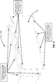
- FIG. 6A illustrates a front-perspective of a battery module arrangement 600 after insertion of the battery module 400 into a battery module compartment in accordance with an embodiment of the disclosure.
- a housing section 605 is arranged over the battery module 400.
- the top folded section 415 of the compartment section 410 contacts an underside of the housing section 605.
- a plurality of "top" endplate-to-compartment clamping arrangements 500C are shown, as well as a plurality of "bottom” endplate-to-compartment clamping arrangements 610.
- the "bottom" endplate-to-compartment clamping arrangements 610 are essentially inverted (e.g., upside-down) versions of the "top" endplate-to-compartment clamping arrangements 500C.
- the bottom folded section 420 of the compartment section 410 may contact a top-side of another housing section (not shown) arranged beneath the battery module 400.
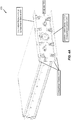
- FIG. 6B illustrates a side-perspective cross-section (taken along the A-A line noted in the front-perspective of FIG. 6A ) of the battery module arrangement 600 of FIG. 6A in accordance with an embodiment of the disclosure.
- a "top" endplate-to-compartment clamping arrangement 500C is shown in a tightened state, whereby endplate section 600B receives contact pressure from the bulged section 610 of the U-shaped clamping bar 500. This contact pressure is transferred to the top compartment flange section 400C, which functions to secure the endplate 405 to the compartment section 410.
- a sealing component 605B (e.g., a rubber gasket, etc.) is arranged inside of the endplate section 600B. So, the contact pressure pressing upon the sealing component 605B between the endplate section 600B and the top compartment flange section 400C functions to seal the battery module compartment.
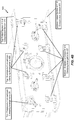
- FIG. 6C illustrates a side-perspective cross-section of the battery module arrangement 600 of FIG. 6A in accordance with another embodiment of the disclosure.
- the "top" endplate-to-compartment clamping arrangement 500C is shown in a loosened state, whereby endplate section 600B does not receive contact pressure from the bulged section 610 of the U-shaped clamping bar 500.
- FIG. 6D illustrates a front-perspective of the battery module arrangement 600 of FIG. 6A in accordance with another embodiment of the disclosure.
- FIG. 6D is identical to FIG. 6C , except that a B-B line is marked across both "top” and “bottom” endplate-to-compartment clamping arrangements.
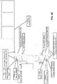
- FIG. 6E illustrates a side-perspective cross-section (taken along the B-B line noted in the front-perspective of FIG. 6D ) of the battery module arrangement 600 of FIG. 6D in accordance with an embodiment of the disclosure.
- FIG. 6D "top" and “bottom” endplate-to-compartment clamping arrangements 500C and 615 are shown in a tightened state, whereby endplate sections 600B and 600E each receive contact pressure from the bulged sections 610 of the U-shaped clamping bars 500 of the "top” and “bottom” endplate-to-compartment clamping arrangements 500C and 615, respectively. This contact pressure presses upon the sealing components 605B and 605E, respectively.
- the sealing components 605B and 605E may be part of one continuous seal (e.g., a rubber gasket, etc.) that runs around the endplate 405. While not shown expressly in FIG. 6E , the bottom folded section 420 of the compartment section 405 may contact a top-side of another housing section (not shown) arranged beneath the battery module 400.
- one continuous seal e.g., a rubber gasket, etc.
- the bulged section 510 of the U-shaped clamping bar 500 may be aligned with a concave section of a respective endplate section, resulting in lower contact pressure in the contact zone.
- the bulged section 510 of the U-shaped clamping bar 500 may be aligned with a flat section of a respective endplate section, resulting in higher contact pressure in the contact zone.
- the bulged section 510 of the U-shaped clamping bar 500 may be aligned with a convex section of a respective endplate section, resulting in lower contact pressure in the contact zone. Accordingly, a shape of a portion of the endplate section that contacts the bulged section 510 of the U-shaped clamping bar 500 can be controlled so as to regulate an amount of contact pressure applied thereto.
- top and bottom endplate-to-compartment clamping arrangements are arranged as mirror images of each other.
- grooves 515-520 of the U-shaped clamping bar 500 are arranged inside holes or cutouts of the top and bottom folded sections 415 and 420 in the above-described embodiments
- the grooves 515-520 could instead be configured to lock onto a separate groove-locking component.
- groove-locking components such as a metal bands may be arranged on the top and bottom folded sections 415 and 420, with the grooves 515-520 being configured to lock onto respective edges of these groove-locking components instead of being locked directly onto the top and bottom folded sections 415 and 420 inside respective holes or cutouts as described above.
- the holes or cutouts need not be made part of the top and bottom folded sections 415 and 420 at all.
- FIG. 7A illustrates a side-perspective of an endplate-to-compartment clamping arrangement 700 in accordance with another embodiment of the disclosure.
- FIG. 7B illustrates a front-perspective of the endplate-to-compartment clamping arrangement 700 in accordance with an embodiment of the disclosure.
- the compartment section 410 is configured with a top folded section 705 that does not include the holes or cutouts shown in the top folded section 415 of FIGS. 4A-4C . Instead, a groove-locking component 710 mounted onto the top folded section 705, and the grooves 515-520 of the U-shaped clamping bar 500 lock onto the groove-locking component 710.
- the groove-locking component 710 may be configured as a metal band that is spot welded onto the top folded section 705. While FIGS.
- top folded section 705 the bottom folded section may be configured similarly (e.g., with groove-locking components mounted onto the top folded section instead of holes or cutouts arranged to catch the grooves 515-520 of the U-shaped clamping bars).
- While the embodiments described above relate primarily to land-based electric vehicles (e.g., cars, trucks, etc.), it will be appreciated that other embodiments can deploy the various battery-related embodiments with respect to any type of electric vehicle (e.g., boats, submarines, airplanes, helicopters, drones, spaceships, space shuttles, rockets, etc.).
- any type of electric vehicle e.g., boats, submarines, airplanes, helicopters, drones, spaceships, space shuttles, rockets, etc.
- the embodiments described above relate primarily to battery module compartments and associated battery modules and insertion-side covers for deployment as part of an energy storage system for an electric vehicle, it will be appreciated that other embodiments can deploy the various battery-related embodiments with respect to any type of energy storage system.
- the above-noted embodiments can be applied to energy storage systems such as home energy storage systems (e.g., providing power storage for a home power system), industrial or commercial energy storage systems (e.g., providing power storage for a commercial or industrial power system), a grid energy storage system (e.g., providing power storage for a public power system, or power grid) and so on.
- the placement of the various battery module compartments in the above-noted embodiments is described as being integrated into a vehicle floor of an electric vehicle.
- the general closed compartment profile design may be extended to battery module mounting areas that can be installed in other locations within the electric vehicle (e.g., in a trunk of the electric vehicle, behind one or more car seats, under a front-hood of the electric vehicle, etc.).
Landscapes
- Chemical & Material Sciences (AREA)
- Chemical Kinetics & Catalysis (AREA)
- Electrochemistry (AREA)
- General Chemical & Material Sciences (AREA)
- Engineering & Computer Science (AREA)
- Combustion & Propulsion (AREA)
- Transportation (AREA)
- Mechanical Engineering (AREA)
- Manufacturing & Machinery (AREA)
- Battery Mounting, Suspending (AREA)
- Arrangement Or Mounting Of Propulsion Units For Vehicles (AREA)
Description
- The present Application for Patent claims the benefit of
U.S. Provisional Application No. 62/571,775 - Embodiments relate to clamp-based fixation of a battery module compartment cover.
- Energy storage systems may rely upon batteries for storage of electrical power. For example, in certain conventional electric vehicle (EV) designs (e.g., fully electric vehicles, hybrid electric vehicles, etc.), a battery housing mounted into an electric vehicle houses a plurality of battery cells (e.g., which may be individually mounted into the battery housing, or alternatively may be grouped within respective battery modules that each contain a set of battery cells, with the respective battery modules being mounted into the battery housing). The battery modules in the battery housing are connected in series via busbars to a battery junction box (BJB), and the BJB distributes electric power provided from the busbars to an electric motor that drives the electric vehicle, as well as various other electrical components of the electric vehicle (e.g., a radio, a control console, a vehicle Heating, Ventilation and Air Conditioning (HVAC) system, internal lights, external lights such as head lights and brake lights, etc.).
EP2722211A1 ,WO2018/081650A1 ,DE102012217248A1 each disclose battery module arrangements. - In an embodiment, a battery module arrangement is provided according to claim 1.
- A more complete appreciation of embodiments of the disclosure will be readily obtained as the same becomes better understood by reference to the following detailed description when considered in connection with the accompanying drawings, which are presented solely for illustration and not limitation of the disclosure, and in which:
-
FIG. 1 illustrates an isometric front-perspective of an exterior framing of a battery module in accordance with an embodiment of the disclosure. -
FIG. 2 depicts the insertion-side cover of the battery module ofFIG. 1 being aligned with a battery module compartment in accordance with an embodiment of the disclosure. -
FIG. 3 illustrates an electric vehicle that configured with a battery module mounting area configured with battery module compartments that permit lateral insertion of respective battery modules in accordance with an embodiment of the disclosure. -
FIG. 4A illustrates an isometric front-perspective of a battery module including an integrated clamp-based insertion-side cover in accordance with an embodiment of the disclosure. -
FIG. 4B illustrates the clamp-based insertion-side cover ofFIG. 4A in more detail. -
FIG. 4C illustrates an isometric rear-perspective of an exterior framing of a battery module ofFIG. 4A in accordance with an embodiment of the disclosure. -
FIG. 5A illustrates an isometric front-perspective of a U-shaped clamping bar in accordance with an embodiment of the disclosure. -
FIG. 5B illustrates a front-perspective and a side-perspective cross-section of the U-shaped clamping bar ofFIG. 5A in accordance with an embodiment of the disclosure. -
FIG. 5C illustrates an endplate-to-compartment clamping arrangement in accordance with an embodiment of the disclosure. -
FIG. 5D illustrates an endplate-to-compartment clamping arrangement in accordance with another embodiment of the disclosure. -
FIG. 6A illustrates a front-perspective of a battery module arrangement after insertion of a battery module into a battery module compartment in accordance with an embodiment of the disclosure. -
FIG. 6B illustrates a side-perspective cross-section of the battery module arrangement ofFIG. 6A in accordance with an embodiment of the disclosure. -
FIG. 6C illustrates a side-perspective cross-section of thebattery module arrangement 600 ofFIG. 6A in accordance with another embodiment of the disclosure. -
FIG. 6D illustrates a front-perspective of a battery module arrangement ofFIG. 6A in accordance with another embodiment of the disclosure. -
FIG. 6E illustrates a side-perspective cross-section of the battery module arrangement ofFIG. 6D in accordance with an embodiment of the disclosure. -
FIG. 7A illustrates a side-perspective of an endplate-to-compartment clamping arrangement in accordance with another embodiment of the disclosure. -
FIG. 7B illustrates a front-perspective of the endplate-to-compartment clamping arrangement ofFIG. 7A in accordance with an embodiment of the disclosure. - Embodiments of the disclosure are provided in the following description and related drawings. Alternate embodiments may be devised without departing from the scope of the appended claims. Additionally, well-known elements of the disclosure will not be described in detail or will be omitted so as not to obscure the relevant details of the disclosure.
- Energy storage systems may rely upon batteries for storage of electrical power. For example, in certain conventional electric vehicle (EV) designs (e.g., fully electric vehicles, hybrid electric vehicles, etc.), a battery housing mounted into an electric vehicle houses a plurality of battery cells (e.g., which may be individually mounted into the battery housing, or alternatively may be grouped within respective battery modules that each contain a set of battery cells, with the respective battery modules being mounted into the battery housing). The battery modules in the battery housing are connected in series via busbars to a battery junction box (BJB), and the BJB distributes electric power provided from the busbars to an electric motor that drives the electric vehicle, as well as various other electrical components of the electric vehicle (e.g., a radio, a control console, a vehicle Heating, Ventilation and Air Conditioning (HVAC) system, internal lights, external lights such as head lights and brake lights, etc.).
-
FIG. 1 illustrates an isometric front-perspective of an exterior framing of abattery module 100 in accordance with an embodiment of the disclosure. In the example ofFIG. 1 , thebattery module 100 is configured for insertion into a battery module compartment. For example, inFIG. 1 , each side of thebattery module 100 includes guidingelements 105 to facilitate insertion into (and/or removal out of) the battery module compartment. In a further example, the guidingelements 105 are configured to fit into grooves inside the battery module compartment to facilitate insertion and/or removal of thebattery module 100. An insertion-side cover 110 (or endplate) is integrated into thebattery module 100. Upon insertion, the insertion-side cover 110 may be attached or affixed to the battery module compartment (e.g., via fixation points 115, such as bolt-holes, which are provisioned on respective flange sections of the battery module 100) to seal thebattery module 100 inside the battery module compartment using a cover (or endplate) integrated sealing system (e.g., rubber ring, paper gasket, sealant adhesive, etc.). While the insertion-side cover 110 is depicted inFIG. 1 as integrated into thebattery module 100, the insertion-side cover 110 may alternatively be independent (or separate) from thebattery module 100, with thebattery module 100 first being inserted into the battery module compartment, after which the insertion-side cover 110 is attached. - Referring to
FIG. 1 , the insertion-side cover 110 includes fixation points 115 provisioned on respective flange sections (e.g., sections of the battery module that protrude out from the frame of the battery module 100), a set of coolingconnections 120, and anoverpressure valve 125. In an example, the fixation points 115 may be bolt-holes through which bolts may be inserted, and the set of coolingconnections 120 may include input and output cooling tube connectors (e.g., through which coolant fluid is pumped into thebattery module 100 for cooling one or more cooling plates). Theoverpressure valve 125 may be configured to open when pressure inside of thebattery module 100 exceeds a threshold (e.g., to avoid an explosion or overpressure by degassing in case of a thermal run away of a battery cell in the battery module 100). -
FIG. 2 depicts the insertion-side cover 110 of thebattery module 100 being aligned with abattery module compartment 200 in accordance with an embodiment of the disclosure. In particular, the fixation points 115 on the respective flange sections of thebattery module 100 are aligned with fixation points 205 on respective flange sections of thebattery module compartment 200. So, once thebattery module 100 is inserted into thebattery module 200, the fixation points 115 and 205 are bolted together to secure (and seal) thebattery module 100 inside thebattery module compartment 200. -
FIG. 3 illustrates anelectric vehicle 300 that configured with a batterymodule mounting area 305 configured with battery module compartments that permit lateral insertion of respective battery modules in accordance with an embodiment of the disclosure. More specifically, battery modules may be inserted into respective battery module compartments on both left and right sides of theelectric vehicle 300. - Referring to
FIG. 3 , the batterymodule mounting area 305 includes, on a left side of theelectric vehicle 300, battery module compartments configured to receive battery modules 310-335 via left-side lateral insertion. InFIG. 3 , battery modules 310-325 are shown at different degrees of lateral insertion, while battery modules 330-335 are shown in a fully-inserted state. While not shown explicitly inFIG. 3 , the batterymodule mounting area 305 may further include, on a right side of theelectric vehicle 300, battery module compartments configured to receive other battery modules via right-side lateral (or side) insertion. More specifically, the insertion-sides of the battery modules 310-335 correspond to the left exterior-facing lateral side of each respective battery module compartment on the left side (longitudinally) of theelectric vehicle 300, and the insertion-sides of the battery modules of each respective battery module compartment on the right side (longitudinally) correspond to the right exterior-facing lateral side of theelectric vehicle 300. Each battery module inFIG. 3 is shown as including the insertion-side cover 110 ofFIGS. 1-2 , which usesfixation points 115 provisioned in flange sections to be secured onto a respective battery module compartment. - Various embodiments of the disclosure described herein relate to reducing a vertical footprint (i.e., a height in a Z direction) of an insertion-side cover that is used to secure (or provide fixation of) of a battery module inside of a battery module compartment. As will be described below, instead of bolting fixation points arranged on flange sections of an insertion-side cover directly to corresponding fixation points arranged on flange sections of the battery module compartment as described above with respect to
FIGS. 1-3 , fixation points are defined in the insertion-side cover which cause contact pressure to be applied between the an endplate of the battery module and the battery module compartment. -
FIG. 4A illustrates an isometric front-perspective of abattery module 400 including an integrated clamp-based insertion-side cover in accordance with an embodiment of the disclosure. Referring toFIG. 4A , the clamp-based insertion-side cover reduces the size of the flange sections and omits the endplate-to-compartment fixation points 115 described above with respect toFIGS. 1-3 , and instead includes a plurality of endplate-to-compartment clamping arrangements (described in more detail below). The clamp-based insertion-side cover includes anendplate 405 of thebattery module 400, and acompartment section 410. Thecompartment section 410 is folded so as to include a top foldedsection 415 and a bottom foldedsection 420. The top and bottom foldedsections -
FIG. 4B illustrates the clamp-based insertion-side cover ofFIG. 4A in more detail. Referring toFIG. 4B , "bottom" endplate-to-compartment clamping arrangements 425 are arranged inside holes of the bottom foldedsection 420, and "top" endplate-to-compartment clamping arrangements 430-435 are arranged inside holes of the top foldedsection 415. The "bottom" endplate-to-compartment clamping arrangements 425 and the "top" endplate-to-compartment clamping arrangements 430 are each shown in a tightened or locked state, while the "top" endplate-to-compartment clamping arrangement 435 is shown in an untightened or loosened state. As will be described in more detail below, tightening of the endplate-to-compartment clamping arrangements functions to secure thebattery module 400 inside a respective battery module compartment, while untightening or loosening the endplate-to-compartment clamping arrangements permits removal of thebattery module 400 from the respective battery module compartment. -
FIG. 4C illustrates an isometric rear-perspective of an exterior framing of abattery module 400 in accordance with an embodiment of the disclosure. Various components of thebattery module 400 are depicted inFIG. 4C (e.g., optical LC communications interface, rear endplate fixation recesses for fixation of thebattery module 400 inside of a battery module compartment, guiding elements for facilitating on sidewalls of thebattery module 400, etc.) but are not labeled or described in detail as such features do not relate specifically to the manner in which the insertion-side cover 405 is secured to the battery module compartment. - Referring to
FIG. 4C , top and bottomcompartment flange sections compartment section 410 are shown. As will be described below in more detail, the top and bottomcompartment flange sections endplate 405 that receive contact pressure from bulged sections of U-shaped clamping bars of endplate-to-compartment clamping arrangements. - Referring to
FIGS. 1-2 , the flange sections for the fixation points 115 and 200 extend upwards and downwards from the battery module compartment so as to create a vertical footprint (e.g., 137.95 millimeters (mm)). By contrast, top and bottomcompartment flange sections compartment section 410 are each shorter than the flange sections for the fixation points 115 and 200 inFIGS. 1-2 , which reduces the vertical footprint required by the battery module 400 (e.g., from 137.95 mm to 106.5 mm). In an example, the top and bottomcompartment flange sections FIGS. 1-2 . This in turn reduces the overall vertical footprint required for the battery housing. - In a further embodiment, the battery housing (and hence, the clamp-based insertion-side cover) may form part of the chassis of an electric vehicle in at least one embodiment, so reducing the vertical footprint of the battery module compartment using the clamp-based insertion-side cover may in turn reduce a vertical footprint (e.g., a height in the Z direction) of the electric vehicle chassis as well.
-
FIG. 5A illustrates an isometric front-perspective of aU-shaped clamping bar 500 in accordance with an embodiment of the disclosure. In particular, theU-shaped clamping bar 500 is folded so as to have to a U-shape, as shown inFIG. 5A . In an example, theU-shaped clamping bar 500 may be made from a metallic material (e.g., steel), and may undergo deformation or plasticization to increase elasticity and to help to ensure that a homogeneous clamping force (or clamping pressure) is applied by equalizing the associated tolerances. TheU-shaped clamping bar 500 is a component of the endplate-to-compartment clamping arrangements 425-435 described above with respect toFIG. 4B . TheU-shaped clamping bar 500 includes a hole (e.g., a screw hole or bolt hole) 505, abulged section 510, andgrooves grooves U-shaped clamping bar 500, as shown inFIG. 5A (e.g., at the same vertical level, such that both grooves 515-520 are aligned with the top folded section when a screw inside of thehole 505 is tightened). - In an example, the "U-shape" of the
U-shaped clamping bar 500 may help to protect against theU-shaped clamping bar 500 from falling off thebattery module 400 altogether, while still permitting flexibility of movement while in a loosened state. However, it will be appreciated that other shapes could also accomplish this objective (e.g., a semi-circle, a set of 3 joined bars that meet at right angles for a more rectangular shape, etc.). Accordingly, the "U-shape" of theU-shaped clamping bar 500 is merely representative of one particular embodiment, and is not intended to limit clamping bars in all embodiments to a "U-shape" implementation. -
FIG. 5B illustrates a front-perspective and a side-perspective cross-section (taken along the A-A line noted in the front-perspective) of theU-shaped clamping bar 500 in accordance with an embodiment of the disclosure. -
FIG. 5C illustrates an endplate-to-compartment clamping arrangement 500C in accordance with an embodiment of the disclosure. In particular, the endplate-to-compartment clamping arrangement 500C corresponds to one of the "top" endplate-to-compartment clamping arrangement 430 fromFIG. 4B . InFIG. 5C , ascrew 505C is tightened inside a fixation point in theendplate 405 that is aligned with thehole 505 of theU-shaped clamping bar 500. As thescrew 505C is tightened, the bulgedsection 510 acts as a fulcrum over which theU-shaped clamping bar 500 "rolls" or pivots, which causes thegrooves endplate 405 until thegrooves section 415. As will be appreciated, thegrooves section 415 to facilitate the above-noted locking function. When locked in this manner, the top foldedsection 415 braces theU-shaped clamping bar 500 against further backward movement by supporting the reaction force in response to the clamping. - As the
screw 505C continues to tighten, the bulgedsection 510 is pushed against the endplate 405 (e.g., while thegrooves compartment flange section 400C shown inFIG. 4C (e.g., via an intervening endplate section in the insertion-side cover 405). This contact pressure functions to secure the endplate 405 (and hence, the entire battery module 400) to thecompartment section 410 of the battery module compartment. In an example, theU-shaped clamping bar 500 may be configured to become deformed as contact pressure is increased (e.g., as thescrew 505C is tightened). Moreover, as will be described in more detail below, the contact pressure between theendplate 405 and thecompartment section 410 is configured to form a sealed connection. -
FIG. 5D illustrates an endplate-to-compartment clamping arrangement 500D in accordance with an embodiment of the disclosure. In particular, the endplate-to-compartment clamping arrangement 500D corresponds to the "top" endplate-to-compartment clamping arrangement 435 fromFIG. 4B . InFIG. 5D , ascrew 505D is loosened inside a fixation point of theendplate 405 that is aligned with thehole 505 of theU-shaped clamping bar 500. As thescrew 505D is loosened, the contact pressure from the bulgedsection 510 to the topcompartment flange section 400C is reduced, such that thebattery module 400 is no longer secured inside the battery module compartment and can be removed. In particular, theU-shaped clamping bar 500 is unlocked from the top foldedsection 415, after which thebattery module 400 can be removed from the battery module compartment. - Referring to
FIG. 5D , thescrew 505D may be configured to remain in theU-shaped clamping bar 500 even in a loosened state. In this case, while being loosened, thescrew 505D will reach a point at which thescrew 505D cannot be further loosened, such that thescrew 505D cannot be removed from theU-shaped clamping bar 500. Alternatively, thescrew 505D may be configured to be removable from theU-shaped clamping bar 500 if the loosening of thescrew 505D exceeds a threshold. -
FIG. 6A illustrates a front-perspective of abattery module arrangement 600 after insertion of thebattery module 400 into a battery module compartment in accordance with an embodiment of the disclosure. - Referring to
FIG. 6A , a housing section 605 is arranged over thebattery module 400. In an example, the top foldedsection 415 of thecompartment section 410 contacts an underside of the housing section 605. A plurality of "top" endplate-to-compartment clamping arrangements 500C are shown, as well as a plurality of "bottom" endplate-to-compartment clamping arrangements 610. The "bottom" endplate-to-compartment clamping arrangements 610 are essentially inverted (e.g., upside-down) versions of the "top" endplate-to-compartment clamping arrangements 500C. In an example, while not shown expressly inFIG. 6A , the bottom foldedsection 420 of thecompartment section 410 may contact a top-side of another housing section (not shown) arranged beneath thebattery module 400. -
FIG. 6B illustrates a side-perspective cross-section (taken along the A-A line noted in the front-perspective ofFIG. 6A ) of thebattery module arrangement 600 ofFIG. 6A in accordance with an embodiment of the disclosure. InFIG. 6B , a "top" endplate-to-compartment clamping arrangement 500C is shown in a tightened state, wherebyendplate section 600B receives contact pressure from the bulged section 610 of theU-shaped clamping bar 500. This contact pressure is transferred to the topcompartment flange section 400C, which functions to secure theendplate 405 to thecompartment section 410. Moreover, asealing component 605B (e.g., a rubber gasket, etc.) is arranged inside of theendplate section 600B. So, the contact pressure pressing upon thesealing component 605B between theendplate section 600B and the topcompartment flange section 400C functions to seal the battery module compartment. -
FIG. 6C illustrates a side-perspective cross-section of thebattery module arrangement 600 ofFIG. 6A in accordance with another embodiment of the disclosure. InFIG. 6C , the "top" endplate-to-compartment clamping arrangement 500C is shown in a loosened state, wherebyendplate section 600B does not receive contact pressure from the bulged section 610 of theU-shaped clamping bar 500. -
FIG. 6D illustrates a front-perspective of thebattery module arrangement 600 ofFIG. 6A in accordance with another embodiment of the disclosure.FIG. 6D is identical toFIG. 6C , except that a B-B line is marked across both "top" and "bottom" endplate-to-compartment clamping arrangements. -
FIG. 6E illustrates a side-perspective cross-section (taken along the B-B line noted in the front-perspective ofFIG. 6D ) of thebattery module arrangement 600 ofFIG. 6D in accordance with an embodiment of the disclosure. InFIG. 6D , "top" and "bottom" endplate-to-compartment clamping arrangements endplate sections compartment clamping arrangements components components endplate 405. While not shown expressly inFIG. 6E , the bottom foldedsection 420 of thecompartment section 405 may contact a top-side of another housing section (not shown) arranged beneath thebattery module 400. - In a further embodiment, the bulged
section 510 of theU-shaped clamping bar 500 may be aligned with a concave section of a respective endplate section, resulting in lower contact pressure in the contact zone. In an alternative embodiment, the bulgedsection 510 of theU-shaped clamping bar 500 may be aligned with a flat section of a respective endplate section, resulting in higher contact pressure in the contact zone. In an alternative embodiment, the bulgedsection 510 of theU-shaped clamping bar 500 may be aligned with a convex section of a respective endplate section, resulting in lower contact pressure in the contact zone. Accordingly, a shape of a portion of the endplate section that contacts the bulgedsection 510 of theU-shaped clamping bar 500 can be controlled so as to regulate an amount of contact pressure applied thereto. - While some embodiments have been described above with respect to "top" endplate-to-compartment clamping arrangements, these descriptions also apply to "bottom" endplate-to-compartment clamping arrangements. In particular, in various embodiments, the "top" and "bottom" endplate-to-compartment clamping arrangements are arranged as mirror images of each other.
- Further, while the grooves 515-520 of the
U-shaped clamping bar 500 are arranged inside holes or cutouts of the top and bottom foldedsections sections sections sections -
FIG. 7A illustrates a side-perspective of an endplate-to-compartment clamping arrangement 700 in accordance with another embodiment of the disclosure.FIG. 7B illustrates a front-perspective of the endplate-to-compartment clamping arrangement 700 in accordance with an embodiment of the disclosure. - Referring to
FIGS. 7A-7B , thecompartment section 410 is configured with a top foldedsection 705 that does not include the holes or cutouts shown in the top foldedsection 415 ofFIGS. 4A-4C . Instead, a groove-lockingcomponent 710 mounted onto the top foldedsection 705, and the grooves 515-520 of theU-shaped clamping bar 500 lock onto the groove-lockingcomponent 710. In an example, the groove-lockingcomponent 710 may be configured as a metal band that is spot welded onto the top foldedsection 705. WhileFIGS. 7A-7B are described with respect to the top foldedsection 705, it will be appreciated that the bottom folded section may be configured similarly (e.g., with groove-locking components mounted onto the top folded section instead of holes or cutouts arranged to catch the grooves 515-520 of the U-shaped clamping bars). - While the embodiments described above relate primarily to land-based electric vehicles (e.g., cars, trucks, etc.), it will be appreciated that other embodiments can deploy the various battery-related embodiments with respect to any type of electric vehicle (e.g., boats, submarines, airplanes, helicopters, drones, spaceships, space shuttles, rockets, etc.).
- While the embodiments described above relate primarily to battery module compartments and associated battery modules and insertion-side covers for deployment as part of an energy storage system for an electric vehicle, it will be appreciated that other embodiments can deploy the various battery-related embodiments with respect to any type of energy storage system. For example, besides electric vehicles, the above-noted embodiments can be applied to energy storage systems such as home energy storage systems (e.g., providing power storage for a home power system), industrial or commercial energy storage systems (e.g., providing power storage for a commercial or industrial power system), a grid energy storage system (e.g., providing power storage for a public power system, or power grid) and so on.
- As will be appreciated, the placement of the various battery module compartments in the above-noted embodiments is described as being integrated into a vehicle floor of an electric vehicle. However, it will be appreciated that the general closed compartment profile design may be extended to battery module mounting areas that can be installed in other locations within the electric vehicle (e.g., in a trunk of the electric vehicle, behind one or more car seats, under a front-hood of the electric vehicle, etc.).
Claims (11)
- A battery module arrangement configured for deployment with respect to a battery module compartment within a battery module mounting area of an energy storage system, comprising:a battery module (400) configured to be inserted into and/or removed from an interior space of the battery module compartment via an insertion-side of the battery module compartment;a clamp-based insertion-side cover configured to be closed over the insertion-side of the battery module compartment,wherein the clamp-based insertion-side cover includes:an endplate (405; 600B; 600E) of the battery module,a compartment section (410) of the battery module compartment, anda plurality of endplate-to-compartment clamping arrangements (425; 430; 435; 615; 500C) that are integrated as part of the clamp-based insertion-side cover and are configured to secure the battery module inside of the battery module compartment by clamping the endplate to the compartment section, characterized in that:wherein each of the plurality of endplate-to-compartment clamping arrangements (425; 430; 435; 615; 500C) includes a screw (505C; 505D), a clamping bar (500), and an endplate section (600B; 600E),wherein the screw (505C; 505D), is configured to be inserted through a hole (505) in the clamping bar (500) and into a fixation point on the endplate (405; 600B; 600E) which causes contact pressure to be applied by the clamping bar (500) to the compartment section (410) in a direction that is different from an insertion direction of the screw (505C; 505D) into the hole.
- The battery module arrangement of claim 1,
wherein the clamping bar in each of the plurality of endplate-to-compartment clamping arrangements (425; 430; 435; 615; 500C) includes a set of grooves, and
wherein each of the plurality of endplate-to-compartment clamping arrangements (425; 430; 435; 615; 500C) further includes a folded section of a compartment section. - The battery module arrangement of claim 2, wherein the clamping bar includes a bulged section that, in response to the screw being tightened, is configured to apply the applied contact pressure to the endplate section that clamps the endplate section to a flange section of the compartment section.
- The battery module arrangement of claim 3, wherein a shape of a portion of the endplate section that contacts the bulged section of the clamping bar is configured to regulate the applied contact pressure.
- The battery module arrangement of claim 4, wherein the shape is convex, concave or flat.
- The battery module arrangement of claim 3, further comprising:a sealing component arranged between the endplate section and the flange section,wherein the applied contact pressure presses upon the sealing component to seal the battery module compartment.
- The battery module arrangement of claim 2, wherein, in response to the screw being tightened, the set of grooves contact and lock onto an edge of a hole that is defined in the folded section to brace the clamping bar against backward movement.
- The battery module arrangement of claim 2, wherein, in response to the screw being tightened, the set of grooves contact and lock onto an edge of a groove-locking component that is attached to the folded section to brace the clamping bar against backward movement.
- The battery module arrangement of claim 2,
wherein the clamping bar is configured as a U-shaped clamping bar, and
wherein the set of grooves include two grooves that are arranged at opposite ends of a U-shape of the U-shaped clamping bar. - The battery module arrangement of claim 2, wherein the clamping bar is constructed from a metallic material that undergoes deformation or plasticization to increase elasticity in order to ensure a homogeneous clamping force.
- The battery module arrangement of claim 1, wherein the plurality of endplate-to-compartment clamping arrangements includes a first set of endplate-to-compartment clamping arrangements arranged along a first edge of the clamp-based insertion-side cover and a second set of endplate-to-compartment clamping arrangements arranged along a second edge of the clamp-based insertion-side cover, the first and second edges being opposing edges of the clamp-based insertion-side cover.
Applications Claiming Priority (3)
| Application Number | Priority Date | Filing Date | Title |
|---|---|---|---|
| US201762571775P | 2017-10-12 | 2017-10-12 | |
| US15/808,155 US20190115572A1 (en) | 2017-10-12 | 2017-11-09 | Clamp-based fixation of battery module compartment cover |
| PCT/US2018/055154 WO2019075017A1 (en) | 2017-10-12 | 2018-10-10 | Clamp-based fixation of battery module compartment cover |
Publications (2)
| Publication Number | Publication Date |
|---|---|
| EP3558735A1 EP3558735A1 (en) | 2019-10-30 |
| EP3558735B1 true EP3558735B1 (en) | 2021-08-11 |
Family
ID=66096632
Family Applications (1)
| Application Number | Title | Priority Date | Filing Date |
|---|---|---|---|
| EP18795890.5A Active EP3558735B1 (en) | 2017-10-12 | 2018-10-10 | Clamp-based fixation of battery module compartment cover |
Country Status (4)
| Country | Link |
|---|---|
| US (1) | US20190115572A1 (en) |
| EP (1) | EP3558735B1 (en) |
| CN (1) | CN111183530A (en) |
| WO (1) | WO2019075017A1 (en) |
Families Citing this family (4)
| Publication number | Priority date | Publication date | Assignee | Title |
|---|---|---|---|---|
| CN112072160B (en) * | 2020-09-21 | 2021-09-10 | 上海空间电源研究所 | Nesting and involution assembly fixture for rectangular flexible battery |
| KR20220041470A (en) * | 2020-09-25 | 2022-04-01 | 현대자동차주식회사 | Battery module and battery pack comprising the same |
| WO2022134123A1 (en) * | 2020-12-26 | 2022-06-30 | 宁德时代新能源科技股份有限公司 | Valve, battery, electric device, and manufacturing device and method for valve |
| CN114096105B (en) * | 2022-01-20 | 2022-04-15 | 国网山东省电力公司菏泽供电公司 | Modular structure of battery integrated controller |
Family Cites Families (7)
| Publication number | Priority date | Publication date | Assignee | Title |
|---|---|---|---|---|
| JP4448111B2 (en) * | 2006-07-31 | 2010-04-07 | 日立ビークルエナジー株式会社 | Power system |
| DE102011009102A1 (en) * | 2011-01-21 | 2012-07-26 | Audi Ag | Battery with a plurality of battery cells |
| CN107946689B (en) * | 2011-04-15 | 2021-01-22 | Cps科技控股有限公司 | Battery system with external thermal management system |
| JP5141795B2 (en) * | 2011-06-20 | 2013-02-13 | 株式会社豊田自動織機 | Battery unit mounting device for vehicle |
| DE102012217248A1 (en) * | 2012-09-25 | 2014-03-27 | Zf Friedrichshafen Ag | Arrangement for securing electric energy storage module in hybrid car, has cells and cooling elements that are connected together and secured to supporting frame for vehicle-mounted connection, via coolant distributor profiles |
| CN206040762U (en) * | 2016-08-31 | 2017-03-22 | 中航锂电(洛阳)有限公司 | Battery box and battery module and battery module anchor clamps thereof |
| US20180123201A1 (en) * | 2016-10-28 | 2018-05-03 | Inevit, Llc | Battery module cooling tube including an integrated turbulator component and method thereof |
-
2017
- 2017-11-09 US US15/808,155 patent/US20190115572A1/en not_active Abandoned
-
2018
- 2018-10-10 EP EP18795890.5A patent/EP3558735B1/en active Active
- 2018-10-10 CN CN201880004225.0A patent/CN111183530A/en active Pending
- 2018-10-10 WO PCT/US2018/055154 patent/WO2019075017A1/en not_active Ceased
Non-Patent Citations (1)
| Title |
|---|
| None * |
Also Published As
| Publication number | Publication date |
|---|---|
| WO2019075017A1 (en) | 2019-04-18 |
| EP3558735A1 (en) | 2019-10-30 |
| CN111183530A (en) | 2020-05-19 |
| US20190115572A1 (en) | 2019-04-18 |
Similar Documents
| Publication | Publication Date | Title |
|---|---|---|
| EP3558735B1 (en) | Clamp-based fixation of battery module compartment cover | |
| KR102608242B1 (en) | Vehicle Body Part, Battery System for Vehicle integrated in the Vehicle Body part and Vehicle with integrated the Battery System | |
| US10811743B2 (en) | Battery system of vehicle | |
| CN110024159B (en) | Welding-free joint of outer plate of battery module | |
| JP7369114B2 (en) | Electric vehicle battery box floor and corresponding vehicle body | |
| US10370035B2 (en) | Motor guidance component configured to direct movement of a dislodged electric motor of an electric vehicle in response to crash forces | |
| KR102396437B1 (en) | Battery module and battery pack including the same | |
| EP3526068B1 (en) | Battery junction box housing configured to direct crash forces in an electric vehicle | |
| US20130071707A1 (en) | Battery cooling system | |
| US11108096B2 (en) | Vehicle battery device | |
| CN213948161U (en) | Vehicle-mounted battery case structure | |
| US11084366B2 (en) | Mounting arrangement of an electrically driven motor vehicle | |
| KR20180006257A (en) | Battery module carrier, battery module and vehicle with a battery system | |
| EP3554874B1 (en) | Clamping bar holder component for a battery module and method thereof | |
| US20250329845A1 (en) | Battery pack and method of manufacturing the same | |
| KR20200017818A (en) | Battery case for electric vehicles | |
| CN116261805B (en) | Box, battery and power consumption device | |
| EP4571976A1 (en) | Battery box, battery and vehicle | |
| US20180304734A1 (en) | High voltage unit | |
| US20250149705A1 (en) | Battery pack | |
| CN119275474A (en) | Inverted battery pack assembly | |
| US12595862B2 (en) | Vent assembly for a sealed enclosure | |
| EP4738582A1 (en) | Pack housing, battery pack, and vehicle including same | |
| CN119749700A (en) | Frame assembly and vehicle |
Legal Events
| Date | Code | Title | Description |
|---|---|---|---|
| STAA | Information on the status of an ep patent application or granted ep patent |
Free format text: STATUS: UNKNOWN |
|
| STAA | Information on the status of an ep patent application or granted ep patent |
Free format text: STATUS: THE INTERNATIONAL PUBLICATION HAS BEEN MADE |
|
| PUAI | Public reference made under article 153(3) epc to a published international application that has entered the european phase |
Free format text: ORIGINAL CODE: 0009012 |
|
| STAA | Information on the status of an ep patent application or granted ep patent |
Free format text: STATUS: REQUEST FOR EXAMINATION WAS MADE |
|
| 17P | Request for examination filed |
Effective date: 20190524 |
|
| AK | Designated contracting states |
Kind code of ref document: A1 Designated state(s): AL AT BE BG CH CY CZ DE DK EE ES FI FR GB GR HR HU IE IS IT LI LT LU LV MC MK MT NL NO PL PT RO RS SE SI SK SM TR |
|
| AX | Request for extension of the european patent |
Extension state: BA ME |
|
| RAP1 | Party data changed (applicant data changed or rights of an application transferred) |
Owner name: TIVENI MERGECO, INC. |
|
| GRAJ | Information related to disapproval of communication of intention to grant by the applicant or resumption of examination proceedings by the epo deleted |
Free format text: ORIGINAL CODE: EPIDOSDIGR1 |
|
| STAA | Information on the status of an ep patent application or granted ep patent |
Free format text: STATUS: GRANT OF PATENT IS INTENDED |
|
| GRAP | Despatch of communication of intention to grant a patent |
Free format text: ORIGINAL CODE: EPIDOSNIGR1 |
|
| DAV | Request for validation of the european patent (deleted) | ||
| DAX | Request for extension of the european patent (deleted) | ||
| INTG | Intention to grant announced |
Effective date: 20201118 |
|
| GRAS | Grant fee paid |
Free format text: ORIGINAL CODE: EPIDOSNIGR3 |
|
| GRAA | (expected) grant |
Free format text: ORIGINAL CODE: 0009210 |
|
| STAA | Information on the status of an ep patent application or granted ep patent |
Free format text: STATUS: THE PATENT HAS BEEN GRANTED |
|
| AK | Designated contracting states |
Kind code of ref document: B1 Designated state(s): AL AT BE BG CH CY CZ DE DK EE ES FI FR GB GR HR HU IE IS IT LI LT LU LV MC MK MT NL NO PL PT RO RS SE SI SK SM TR |
|
| REG | Reference to a national code |
Ref country code: CH Ref legal event code: EP |
|
| REG | Reference to a national code |
Ref country code: DE Ref legal event code: R096 Ref document number: 602018021795 Country of ref document: DE |
|
| REG | Reference to a national code |
Ref country code: IE Ref legal event code: FG4D Ref country code: AT Ref legal event code: REF Ref document number: 1419037 Country of ref document: AT Kind code of ref document: T Effective date: 20210915 |
|
| REG | Reference to a national code |
Ref country code: LT Ref legal event code: MG9D |
|
| REG | Reference to a national code |
Ref country code: NL Ref legal event code: MP Effective date: 20210811 |
|
| REG | Reference to a national code |
Ref country code: AT Ref legal event code: MK05 Ref document number: 1419037 Country of ref document: AT Kind code of ref document: T Effective date: 20210811 |
|
| PG25 | Lapsed in a contracting state [announced via postgrant information from national office to epo] |
Ref country code: RS Free format text: LAPSE BECAUSE OF FAILURE TO SUBMIT A TRANSLATION OF THE DESCRIPTION OR TO PAY THE FEE WITHIN THE PRESCRIBED TIME-LIMIT Effective date: 20210811 Ref country code: SE Free format text: LAPSE BECAUSE OF FAILURE TO SUBMIT A TRANSLATION OF THE DESCRIPTION OR TO PAY THE FEE WITHIN THE PRESCRIBED TIME-LIMIT Effective date: 20210811 Ref country code: HR Free format text: LAPSE BECAUSE OF FAILURE TO SUBMIT A TRANSLATION OF THE DESCRIPTION OR TO PAY THE FEE WITHIN THE PRESCRIBED TIME-LIMIT Effective date: 20210811 Ref country code: ES Free format text: LAPSE BECAUSE OF FAILURE TO SUBMIT A TRANSLATION OF THE DESCRIPTION OR TO PAY THE FEE WITHIN THE PRESCRIBED TIME-LIMIT Effective date: 20210811 Ref country code: FI Free format text: LAPSE BECAUSE OF FAILURE TO SUBMIT A TRANSLATION OF THE DESCRIPTION OR TO PAY THE FEE WITHIN THE PRESCRIBED TIME-LIMIT Effective date: 20210811 Ref country code: BG Free format text: LAPSE BECAUSE OF FAILURE TO SUBMIT A TRANSLATION OF THE DESCRIPTION OR TO PAY THE FEE WITHIN THE PRESCRIBED TIME-LIMIT Effective date: 20211111 Ref country code: AT Free format text: LAPSE BECAUSE OF FAILURE TO SUBMIT A TRANSLATION OF THE DESCRIPTION OR TO PAY THE FEE WITHIN THE PRESCRIBED TIME-LIMIT Effective date: 20210811 Ref country code: LT Free format text: LAPSE BECAUSE OF FAILURE TO SUBMIT A TRANSLATION OF THE DESCRIPTION OR TO PAY THE FEE WITHIN THE PRESCRIBED TIME-LIMIT Effective date: 20210811 Ref country code: NO Free format text: LAPSE BECAUSE OF FAILURE TO SUBMIT A TRANSLATION OF THE DESCRIPTION OR TO PAY THE FEE WITHIN THE PRESCRIBED TIME-LIMIT Effective date: 20211111 Ref country code: PT Free format text: LAPSE BECAUSE OF FAILURE TO SUBMIT A TRANSLATION OF THE DESCRIPTION OR TO PAY THE FEE WITHIN THE PRESCRIBED TIME-LIMIT Effective date: 20211213 |
|
| PG25 | Lapsed in a contracting state [announced via postgrant information from national office to epo] |
Ref country code: PL Free format text: LAPSE BECAUSE OF FAILURE TO SUBMIT A TRANSLATION OF THE DESCRIPTION OR TO PAY THE FEE WITHIN THE PRESCRIBED TIME-LIMIT Effective date: 20210811 Ref country code: LV Free format text: LAPSE BECAUSE OF FAILURE TO SUBMIT A TRANSLATION OF THE DESCRIPTION OR TO PAY THE FEE WITHIN THE PRESCRIBED TIME-LIMIT Effective date: 20210811 Ref country code: GR Free format text: LAPSE BECAUSE OF FAILURE TO SUBMIT A TRANSLATION OF THE DESCRIPTION OR TO PAY THE FEE WITHIN THE PRESCRIBED TIME-LIMIT Effective date: 20211112 |
|
| PG25 | Lapsed in a contracting state [announced via postgrant information from national office to epo] |
Ref country code: NL Free format text: LAPSE BECAUSE OF FAILURE TO SUBMIT A TRANSLATION OF THE DESCRIPTION OR TO PAY THE FEE WITHIN THE PRESCRIBED TIME-LIMIT Effective date: 20210811 |
|
| PG25 | Lapsed in a contracting state [announced via postgrant information from national office to epo] |
Ref country code: DK Free format text: LAPSE BECAUSE OF FAILURE TO SUBMIT A TRANSLATION OF THE DESCRIPTION OR TO PAY THE FEE WITHIN THE PRESCRIBED TIME-LIMIT Effective date: 20210811 |
|
| REG | Reference to a national code |
Ref country code: DE Ref legal event code: R119 Ref document number: 602018021795 Country of ref document: DE |
|
| REG | Reference to a national code |
Ref country code: CH Ref legal event code: PL |
|
| PG25 | Lapsed in a contracting state [announced via postgrant information from national office to epo] |
Ref country code: SM Free format text: LAPSE BECAUSE OF FAILURE TO SUBMIT A TRANSLATION OF THE DESCRIPTION OR TO PAY THE FEE WITHIN THE PRESCRIBED TIME-LIMIT Effective date: 20210811 Ref country code: SK Free format text: LAPSE BECAUSE OF FAILURE TO SUBMIT A TRANSLATION OF THE DESCRIPTION OR TO PAY THE FEE WITHIN THE PRESCRIBED TIME-LIMIT Effective date: 20210811 Ref country code: RO Free format text: LAPSE BECAUSE OF FAILURE TO SUBMIT A TRANSLATION OF THE DESCRIPTION OR TO PAY THE FEE WITHIN THE PRESCRIBED TIME-LIMIT Effective date: 20210811 Ref country code: EE Free format text: LAPSE BECAUSE OF FAILURE TO SUBMIT A TRANSLATION OF THE DESCRIPTION OR TO PAY THE FEE WITHIN THE PRESCRIBED TIME-LIMIT Effective date: 20210811 Ref country code: CZ Free format text: LAPSE BECAUSE OF FAILURE TO SUBMIT A TRANSLATION OF THE DESCRIPTION OR TO PAY THE FEE WITHIN THE PRESCRIBED TIME-LIMIT Effective date: 20210811 Ref country code: AL Free format text: LAPSE BECAUSE OF FAILURE TO SUBMIT A TRANSLATION OF THE DESCRIPTION OR TO PAY THE FEE WITHIN THE PRESCRIBED TIME-LIMIT Effective date: 20210811 |
|
| PLBE | No opposition filed within time limit |
Free format text: ORIGINAL CODE: 0009261 |
|
| STAA | Information on the status of an ep patent application or granted ep patent |
Free format text: STATUS: NO OPPOSITION FILED WITHIN TIME LIMIT |
|
| REG | Reference to a national code |
Ref country code: BE Ref legal event code: MM Effective date: 20211031 |
|
| PG25 | Lapsed in a contracting state [announced via postgrant information from national office to epo] |
Ref country code: MC Free format text: LAPSE BECAUSE OF FAILURE TO SUBMIT A TRANSLATION OF THE DESCRIPTION OR TO PAY THE FEE WITHIN THE PRESCRIBED TIME-LIMIT Effective date: 20210811 |
|
| 26N | No opposition filed |
Effective date: 20220512 |
|
| PG25 | Lapsed in a contracting state [announced via postgrant information from national office to epo] |
Ref country code: LU Free format text: LAPSE BECAUSE OF NON-PAYMENT OF DUE FEES Effective date: 20211010 Ref country code: IT Free format text: LAPSE BECAUSE OF FAILURE TO SUBMIT A TRANSLATION OF THE DESCRIPTION OR TO PAY THE FEE WITHIN THE PRESCRIBED TIME-LIMIT Effective date: 20210811 Ref country code: DE Free format text: LAPSE BECAUSE OF NON-PAYMENT OF DUE FEES Effective date: 20220503 Ref country code: BE Free format text: LAPSE BECAUSE OF NON-PAYMENT OF DUE FEES Effective date: 20211031 |
|
| PG25 | Lapsed in a contracting state [announced via postgrant information from national office to epo] |
Ref country code: SI Free format text: LAPSE BECAUSE OF FAILURE TO SUBMIT A TRANSLATION OF THE DESCRIPTION OR TO PAY THE FEE WITHIN THE PRESCRIBED TIME-LIMIT Effective date: 20210811 Ref country code: LI Free format text: LAPSE BECAUSE OF NON-PAYMENT OF DUE FEES Effective date: 20211031 Ref country code: CH Free format text: LAPSE BECAUSE OF NON-PAYMENT OF DUE FEES Effective date: 20211031 |
|
| PG25 | Lapsed in a contracting state [announced via postgrant information from national office to epo] |
Ref country code: FR Free format text: LAPSE BECAUSE OF NON-PAYMENT OF DUE FEES Effective date: 20211011 |
|
| PG25 | Lapsed in a contracting state [announced via postgrant information from national office to epo] |
Ref country code: IE Free format text: LAPSE BECAUSE OF NON-PAYMENT OF DUE FEES Effective date: 20211010 |
|
| GBPC | Gb: european patent ceased through non-payment of renewal fee |
Effective date: 20221010 |
|
| PG25 | Lapsed in a contracting state [announced via postgrant information from national office to epo] |
Ref country code: CY Free format text: LAPSE BECAUSE OF FAILURE TO SUBMIT A TRANSLATION OF THE DESCRIPTION OR TO PAY THE FEE WITHIN THE PRESCRIBED TIME-LIMIT Effective date: 20210811 |
|
| PG25 | Lapsed in a contracting state [announced via postgrant information from national office to epo] |
Ref country code: HU Free format text: LAPSE BECAUSE OF FAILURE TO SUBMIT A TRANSLATION OF THE DESCRIPTION OR TO PAY THE FEE WITHIN THE PRESCRIBED TIME-LIMIT; INVALID AB INITIO Effective date: 20181010 |
|
| PG25 | Lapsed in a contracting state [announced via postgrant information from national office to epo] |
Ref country code: GB Free format text: LAPSE BECAUSE OF NON-PAYMENT OF DUE FEES Effective date: 20221010 |
|
| PG25 | Lapsed in a contracting state [announced via postgrant information from national office to epo] |
Ref country code: MK Free format text: LAPSE BECAUSE OF FAILURE TO SUBMIT A TRANSLATION OF THE DESCRIPTION OR TO PAY THE FEE WITHIN THE PRESCRIBED TIME-LIMIT Effective date: 20210811 |
|
| PG25 | Lapsed in a contracting state [announced via postgrant information from national office to epo] |
Ref country code: MT Free format text: LAPSE BECAUSE OF FAILURE TO SUBMIT A TRANSLATION OF THE DESCRIPTION OR TO PAY THE FEE WITHIN THE PRESCRIBED TIME-LIMIT Effective date: 20210811 |
|
| PG25 | Lapsed in a contracting state [announced via postgrant information from national office to epo] |
Ref country code: TR Free format text: LAPSE BECAUSE OF FAILURE TO SUBMIT A TRANSLATION OF THE DESCRIPTION OR TO PAY THE FEE WITHIN THE PRESCRIBED TIME-LIMIT Effective date: 20210811 |