EP3558697B1 - Wheel assembly - Google Patents
Wheel assembly Download PDFInfo
- Publication number
- EP3558697B1 EP3558697B1 EP17811946.7A EP17811946A EP3558697B1 EP 3558697 B1 EP3558697 B1 EP 3558697B1 EP 17811946 A EP17811946 A EP 17811946A EP 3558697 B1 EP3558697 B1 EP 3558697B1
- Authority
- EP
- European Patent Office
- Prior art keywords
- wheel assembly
- chamber
- wheel
- actuator
- substance
- Prior art date
- Legal status (The legal status is an assumption and is not a legal conclusion. Google has not performed a legal analysis and makes no representation as to the accuracy of the status listed.)
- Active
Links
- 239000000126 substance Substances 0.000 claims description 56
- 239000012530 fluid Substances 0.000 claims description 49
- 230000007704 transition Effects 0.000 claims description 47
- 239000002245 particle Substances 0.000 claims description 14
- 229920001971 elastomer Polymers 0.000 claims description 8
- 239000000806 elastomer Substances 0.000 claims description 6
- 230000005684 electric field Effects 0.000 claims description 4
- 230000007246 mechanism Effects 0.000 claims description 4
- 230000004044 response Effects 0.000 claims description 3
- 239000007789 gas Substances 0.000 description 26
- XEEYBQQBJWHFJM-UHFFFAOYSA-N Iron Chemical compound [Fe] XEEYBQQBJWHFJM-UHFFFAOYSA-N 0.000 description 7
- 239000000463 material Substances 0.000 description 5
- 239000003921 oil Substances 0.000 description 5
- PXHVJJICTQNCMI-UHFFFAOYSA-N Nickel Chemical compound [Ni] PXHVJJICTQNCMI-UHFFFAOYSA-N 0.000 description 4
- XUIMIQQOPSSXEZ-UHFFFAOYSA-N Silicon Chemical compound [Si] XUIMIQQOPSSXEZ-UHFFFAOYSA-N 0.000 description 3
- 230000008859 change Effects 0.000 description 3
- 230000009194 climbing Effects 0.000 description 3
- 229910052742 iron Inorganic materials 0.000 description 3
- 239000006249 magnetic particle Substances 0.000 description 3
- 239000010703 silicon Substances 0.000 description 3
- 229910052710 silicon Inorganic materials 0.000 description 3
- XLYOFNOQVPJJNP-UHFFFAOYSA-N water Substances O XLYOFNOQVPJJNP-UHFFFAOYSA-N 0.000 description 3
- IJGRMHOSHXDMSA-UHFFFAOYSA-N Atomic nitrogen Chemical compound N#N IJGRMHOSHXDMSA-UHFFFAOYSA-N 0.000 description 2
- CURLTUGMZLYLDI-UHFFFAOYSA-N Carbon dioxide Chemical compound O=C=O CURLTUGMZLYLDI-UHFFFAOYSA-N 0.000 description 2
- 238000010521 absorption reaction Methods 0.000 description 2
- 239000010941 cobalt Substances 0.000 description 2
- 229910017052 cobalt Inorganic materials 0.000 description 2
- GUTLYIVDDKVIGB-UHFFFAOYSA-N cobalt atom Chemical compound [Co] GUTLYIVDDKVIGB-UHFFFAOYSA-N 0.000 description 2
- 238000006073 displacement reaction Methods 0.000 description 2
- 230000000694 effects Effects 0.000 description 2
- SZVJSHCCFOBDDC-UHFFFAOYSA-N ferrosoferric oxide Chemical compound O=[Fe]O[Fe]O[Fe]=O SZVJSHCCFOBDDC-UHFFFAOYSA-N 0.000 description 2
- 229910052759 nickel Inorganic materials 0.000 description 2
- 238000005086 pumping Methods 0.000 description 2
- 239000005060 rubber Substances 0.000 description 2
- 230000035939 shock Effects 0.000 description 2
- 239000007787 solid Substances 0.000 description 2
- 229910001220 stainless steel Inorganic materials 0.000 description 2
- 244000075850 Avena orientalis Species 0.000 description 1
- 235000007319 Avena orientalis Nutrition 0.000 description 1
- 239000004215 Carbon black (E152) Substances 0.000 description 1
- 229910000976 Electrical steel Inorganic materials 0.000 description 1
- 241001061260 Emmelichthys struhsakeri Species 0.000 description 1
- 229910000640 Fe alloy Inorganic materials 0.000 description 1
- 229910001209 Low-carbon steel Inorganic materials 0.000 description 1
- ZOKXTWBITQBERF-UHFFFAOYSA-N Molybdenum Chemical compound [Mo] ZOKXTWBITQBERF-UHFFFAOYSA-N 0.000 description 1
- 240000007594 Oryza sativa Species 0.000 description 1
- 235000007164 Oryza sativa Nutrition 0.000 description 1
- ARZRWOQKELGYTN-UHFFFAOYSA-N [V].[Mn] Chemical compound [V].[Mn] ARZRWOQKELGYTN-UHFFFAOYSA-N 0.000 description 1
- 239000000853 adhesive Substances 0.000 description 1
- 230000001070 adhesive effect Effects 0.000 description 1
- 239000002199 base oil Substances 0.000 description 1
- 239000011324 bead Substances 0.000 description 1
- 229910002092 carbon dioxide Inorganic materials 0.000 description 1
- 239000001569 carbon dioxide Substances 0.000 description 1
- 235000013339 cereals Nutrition 0.000 description 1
- 230000009849 deactivation Effects 0.000 description 1
- 235000014113 dietary fatty acids Nutrition 0.000 description 1
- 239000013013 elastic material Substances 0.000 description 1
- 239000000194 fatty acid Substances 0.000 description 1
- 229930195729 fatty acid Natural products 0.000 description 1
- 150000004665 fatty acids Chemical class 0.000 description 1
- 239000011554 ferrofluid Substances 0.000 description 1
- 239000002783 friction material Substances 0.000 description 1
- 239000008187 granular material Substances 0.000 description 1
- 239000005337 ground glass Substances 0.000 description 1
- 231100001261 hazardous Toxicity 0.000 description 1
- 239000010720 hydraulic oil Substances 0.000 description 1
- 229930195733 hydrocarbon Natural products 0.000 description 1
- 150000002430 hydrocarbons Chemical class 0.000 description 1
- UQSXHKLRYXJYBZ-UHFFFAOYSA-N iron oxide Inorganic materials [Fe]=O UQSXHKLRYXJYBZ-UHFFFAOYSA-N 0.000 description 1
- 235000013980 iron oxide Nutrition 0.000 description 1
- VBMVTYDPPZVILR-UHFFFAOYSA-N iron(2+);oxygen(2-) Chemical class [O-2].[Fe+2] VBMVTYDPPZVILR-UHFFFAOYSA-N 0.000 description 1
- JEIPFZHSYJVQDO-UHFFFAOYSA-N iron(III) oxide Inorganic materials O=[Fe]O[Fe]=O JEIPFZHSYJVQDO-UHFFFAOYSA-N 0.000 description 1
- 239000007788 liquid Substances 0.000 description 1
- 229910052751 metal Inorganic materials 0.000 description 1
- 239000002184 metal Substances 0.000 description 1
- 238000000034 method Methods 0.000 description 1
- 239000002480 mineral oil Substances 0.000 description 1
- 230000004048 modification Effects 0.000 description 1
- 238000012986 modification Methods 0.000 description 1
- 229910052750 molybdenum Inorganic materials 0.000 description 1
- 239000011733 molybdenum Substances 0.000 description 1
- 229910052757 nitrogen Inorganic materials 0.000 description 1
- 230000003287 optical effect Effects 0.000 description 1
- 239000012188 paraffin wax Substances 0.000 description 1
- 239000004033 plastic Substances 0.000 description 1
- 229920000642 polymer Polymers 0.000 description 1
- 229920001296 polysiloxane Polymers 0.000 description 1
- 230000002441 reversible effect Effects 0.000 description 1
- 235000009566 rice Nutrition 0.000 description 1
- 150000003839 salts Chemical class 0.000 description 1
- 239000004576 sand Substances 0.000 description 1
- 229920002545 silicone oil Polymers 0.000 description 1
- 239000010935 stainless steel Substances 0.000 description 1
- 239000004094 surface-active agent Substances 0.000 description 1
- 239000000725 suspension Substances 0.000 description 1
- 229920003051 synthetic elastomer Polymers 0.000 description 1
- 239000005061 synthetic rubber Substances 0.000 description 1
- 230000009466 transformation Effects 0.000 description 1
- 238000003466 welding Methods 0.000 description 1
Images



Classifications
-
- B—PERFORMING OPERATIONS; TRANSPORTING
- B60—VEHICLES IN GENERAL
- B60C—VEHICLE TYRES; TYRE INFLATION; TYRE CHANGING; CONNECTING VALVES TO INFLATABLE ELASTIC BODIES IN GENERAL; DEVICES OR ARRANGEMENTS RELATED TO TYRES
- B60C5/00—Inflatable pneumatic tyres or inner tubes
- B60C5/20—Inflatable pneumatic tyres or inner tubes having multiple separate inflatable chambers
-
- B—PERFORMING OPERATIONS; TRANSPORTING
- B60—VEHICLES IN GENERAL
- B60B—VEHICLE WHEELS; CASTORS; AXLES FOR WHEELS OR CASTORS; INCREASING WHEEL ADHESION
- B60B9/00—Wheels of high resiliency, e.g. with conical interacting pressure-surfaces
- B60B9/18—Wheels of high resiliency, e.g. with conical interacting pressure-surfaces using fluid
-
- A—HUMAN NECESSITIES
- A61—MEDICAL OR VETERINARY SCIENCE; HYGIENE
- A61G—TRANSPORT, PERSONAL CONVEYANCES, OR ACCOMMODATION SPECIALLY ADAPTED FOR PATIENTS OR DISABLED PERSONS; OPERATING TABLES OR CHAIRS; CHAIRS FOR DENTISTRY; FUNERAL DEVICES
- A61G5/00—Chairs or personal conveyances specially adapted for patients or disabled persons, e.g. wheelchairs
- A61G5/06—Chairs or personal conveyances specially adapted for patients or disabled persons, e.g. wheelchairs with obstacle mounting facilities, e.g. for climbing stairs, kerbs or steps
-
- B—PERFORMING OPERATIONS; TRANSPORTING
- B60—VEHICLES IN GENERAL
- B60B—VEHICLE WHEELS; CASTORS; AXLES FOR WHEELS OR CASTORS; INCREASING WHEEL ADHESION
- B60B2200/00—Type of product being used or applied
- B60B2200/20—Furniture or medical appliances
- B60B2200/22—Chairs
-
- B—PERFORMING OPERATIONS; TRANSPORTING
- B60—VEHICLES IN GENERAL
- B60B—VEHICLE WHEELS; CASTORS; AXLES FOR WHEELS OR CASTORS; INCREASING WHEEL ADHESION
- B60B2900/00—Purpose of invention
- B60B2900/30—Increase in
- B60B2900/313—Resiliency
-
- B—PERFORMING OPERATIONS; TRANSPORTING
- B60—VEHICLES IN GENERAL
- B60B—VEHICLE WHEELS; CASTORS; AXLES FOR WHEELS OR CASTORS; INCREASING WHEEL ADHESION
- B60B2900/00—Purpose of invention
- B60B2900/50—Improvement of
- B60B2900/551—Handling of obstacles or difficult terrains
-
- B—PERFORMING OPERATIONS; TRANSPORTING
- B60—VEHICLES IN GENERAL
- B60C—VEHICLE TYRES; TYRE INFLATION; TYRE CHANGING; CONNECTING VALVES TO INFLATABLE ELASTIC BODIES IN GENERAL; DEVICES OR ARRANGEMENTS RELATED TO TYRES
- B60C7/00—Non-inflatable or solid tyres
- B60C7/10—Non-inflatable or solid tyres characterised by means for increasing resiliency
- B60C7/12—Non-inflatable or solid tyres characterised by means for increasing resiliency using enclosed chambers, e.g. gas-filled
- B60C7/121—Non-inflatable or solid tyres characterised by means for increasing resiliency using enclosed chambers, e.g. gas-filled enclosed chambers defined by a distinct core
-
- B—PERFORMING OPERATIONS; TRANSPORTING
- B60—VEHICLES IN GENERAL
- B60G—VEHICLE SUSPENSION ARRANGEMENTS
- B60G2300/00—Indexing codes relating to the type of vehicle
- B60G2300/24—Wheelchairs
Definitions
- the present invention relates to a wheel assembly, for example a wheel assembly for a vehicle.
- Wheels typically include an inflatable tyre that provides traction and shock absorption through deformation of the tyre casing.
- the deformation of the tyre casing allows for increased grip on obstacles and surfaces.
- Some wheels have grousers that can dig into a soft obstacle, or abut against a hard one, in order to provide traction for overcoming larger obstacles.
- a wheel is only able to overcome an obstacle having a height of less than about one third of the diameter of the wheel.
- JP2008 018206 discloses a stair climbing wheelchair with low pressure tyres.
- a wheel assembly comprising a wheel, the wheel having a hub and a rim concentrically mounted to the hub; a plurality of deformable chambers disposed outwardly of the rim, each chamber extending about a discreet portion of the wheel and containing a transition substance; and an actuator configured to transform the transition substance within each chamber between:
- the actuator may be configured to selectively operate the transition substance within each deformable chamber independently of the transition substance within any other deformable chamber.
- the wheel may further comprise a plurality of supporting fins extending radially between adjacent deformable chambers.
- the wheel may further comprise a compressible layer disposed between the deformable chamber and the wheel.
- the compressible layer may comprise a pneumatic bladder.
- the wheel assembly may further comprise a sensor arranged to detect deformation of the deformable chamber.
- the wheel assembly may further comprise a sensor arranged to detect the presence of an obstacle.
- the actuator may be configured to transform the transition substance between the fluid state and the rigid state in response to a signal generated by the sensor.
- the transition substance may comprise jamming particles and an interstitial gas.
- the actuator may be configured to evacuate the interstitial gas from the deformable chamber to transform the transition substance from the fluid state to the rigid state.
- the actuator may be configured to move gas into the deformable chamber to transform the transition substance from the rigid state to the fluid state after said obstacle has been overcome.
- the actuator may comprise a pump.
- the deformable chamber may comprise a self-inflation mechanism.
- the self-inflation mechanism may comprise a biasing member.
- the transition substance may comprise a rheological substance and the actuator may be configured to alter the viscosity of the rheological substance.
- the rheological substance is a magnetorheological fluid and the actuator comprises an electromagnet.
- the rheological substance is an electrorheological fluid and the actuator is configured to generate an electric field.
- the rheological substance is an electrorheological elastomer and the actuator is configured to generate an electric and/or magnetic field.
- the wheel assembly may further comprise a tread disposed outwardly of the deformable chamber to contact the ground during use of the wheel assembly.
- the tread may comprise a plurality of grousers.
- the deformable chamber may be attached to the wheel.
- the deformable chamber may comprise a flexible wall defining a closed tube.
- the wheel is a drive wheel configured to be coupled to a drive motor.
- a vehicle comprising at least one wheel assembly as described above.
- a wheelchair comprising at least one wheel assembly as described above.
- FIG. 1 An embodiment of a wheel assembly 1 according to the invention is illustrated by FIG. 1 .
- the wheel assembly 1 comprises a wheel that is formed of a hub 2 and a rim 3 concentrically mounted to the hub 2 by a connecting wall 4.
- the connecting wall 4 comprises a number of spokes arranged between the rim 3 and the hub 2; however other arrangements are equally feasible, for example a solid wheel, or a solid wheel in which cuts outs are made in the connecting wall 4 for lightness.
- the wheel may be formed of a disc.
- the illustrated wheel assembly 1 is a drive wheel, meaning that torque is applied to the wheel assembly 1 to provide a driving force.
- the axle 5 is a drive axle that is coupled to a motor or other drive means.
- the drive axle can be coupled to the hub 2 in a number of conventional means, for example a spine or key.
- the wheel may not be a drive wheel, for example the wheel may be a passive trailer wheel or a passive steering wheel.
- the wheel assembly 1 described herein may be used in a wide variety of different applications.
- the wheel assembly 1 can be used on a vehicle.
- the wheel assembly 1 is used on a wheelchair.
- the wheel assembly 1 is used on a mobility vehicle, for example a mobility scooter.
- the wheel assembly 1 is used on search and rescue vehicles and specialised off-road vehicles.
- the wheel assembly 1 may be used on remotely controlled or autonomous vehicles, including space exploration vehicles or vehicles for exploring hazardous environments.
- the wheel assembly of FIG. 1 further comprises four chambers 6 arranged about the circumference of the rim 3.
- Each chamber 6 is enclosed by a continuous flexible wall 7 that forms a closed ended elongate tube 8.
- Each tube 8 is arranged about a discrete portion of the rim 3 and is closely spaced to an adjacent tube 8 so that the four tubes 8 defining the four chambers 6 provide full coverage of the rim 3.
- the chambers 6 are coupled to the rim 3 such that torque can be transferred between the rim 3 and the flexible wall 7.
- the flexible wall 7 may be adhered, welded or otherwise attached to an outer surface of the rim 3.
- supporting fins 9 can optionally be provided between adjacent chambers 6.
- Each fin 9 extends radially outward of the rim 3 to provide a surface against which a portion of the flexible wall 7 is supported, that is, the portion of wall 7 defining one of the longitudinal ends of the respective tube 8. Therefore, as the wheel 1 is caused to rotate, torque is transferred from the hub 2 to each of the supporting fins 9 and, in turn, to each flexible wall 7 of each respective chamber 6.
- Each chamber 6 is filled with a transition substance 15 that is configured to transform from a fluid state that allows the chamber 6 to deform, and a rigid state that maintains the chamber 6 in its deformed state. Therefore, during use, as the wheel assembly 1 encounters an obstacle a chamber 6 can be deformed while the transition substance 15 is in a fluid state. Then, the transition substance 15 can be transformed to its rigid state to maintain the chamber 6 in its deformed shape. This can provide increased purchase on the obstacle, allowing the wheel assembly 1 to more easily overcome the obstacle.
- An actuator 14 is provided to effect transformation of the transition substance 15 between the fluid state and the rigid state, as explained further hereinafter.
- the transition substance 15 In normal use, as the wheel 1 rolls along a flat surface, the transition substance 15 is in the fluid state. This allows the wheel 1 to provide a degree of compliancy over irregularities in the surface by displacement of the flexible wall 7, providing traction and shock absorption.
- the wheel is described overcoming a step 10, such as a kerb.
- the step 10 has vertical 11 and horizontal faces 12 that are adjoined by an edge 13.
- the step 10 has a height that is slightly greater than one half of the diameter of the wheel, meaning that conventional wheels will struggle to overcome this step 10.
- the transition 15 substance is in the fluid state.
- the wheel assembly 1 rolls up against the step 10 so that the flexible wall 7 of the chamber 6 adjacent the step 10 conforms around the edge 13 of the step 10.
- the chamber 6 has deformed about the edge 13 such that a part of the chamber 6 overlies the horizontal face 12 of the step.
- the deformed shape of the chamber 6 is referred to as a conformal shape.
- the actuator 14 is activated and the transition substance 15 is made rigid so as to prevent further deformation of the flexible wall 7 and maintain the chamber 6 in its conformal shape.
- the deformed flexible wall 7 then effectively acts as a grouser, allowing the portion of the flexible wall 7 in contact with the horizontal face 12 of the step 10 to provide purchase on the step 10 as the wheel 1 is rotated.
- the wheel assembly 1 may then roll over the edge 13 of the step 10 and onto the horizontal face 12 with reduced risk of slippage.
- the actuator 14 restores the transition substance 15 to its fluid state allowing the flexible wall 7 to take up its natural shape for normal operation.
- FIGS. 3A to 3C A first example of the actuator 14 and transition substance 15 will be described with reference to FIGS. 3A to 3C .
- FIGS. illustrate one chamber 6 of the wheel assembly 1 described with reference to FIG. 1 to FIG. 2E .
- the transition substance 15 comprises jamming particles 19 and an interstitial gas 20.
- This embodiment relies on the principle of jamming transition to effect the change between the fluid state and the rigid state, whereby the interstitial gas 20 is evacuated to lock the jamming particles 19 together in the rigid state within the chamber 6.
- the chamber 6 is filled with interstitial gas 20.
- the compressibility of the gas 20 and flexibility of the flexible wall 7 allows the chamber 6 to conform to the shape of the obstacle.
- FIG. 3B As the chamber 6 comes into contact with the obstacle the flexible wall 7 deforms, allowing the chamber 6 to conform to the shape of the obstacle.
- FIG. 3C the gas 20 is evacuated from the chamber 6, which draws the flexible wall 7 around the jamming particles 19 locking them together so that the flexible wall 7 is rigidified in the deformed state and the chamber 6 is maintained in its conformal state.
- the rigidified chamber 6 provides increased purchase between the wheel assembly 1 and the obstacle, allowing the wheel to overcome the obstacle as described previously.
- the actuator 14 comprises a pump 22 for evacuating the interstitial gas 20 from the chambers 6.
- a valve 21 is provided between the pump and each chamber 6. The valve 21 may be opened and closed by the actuator 14.
- the pump 22 can either be mounted to the wheel 1, as shown, or can be mounted to the vehicle to which the wheel 1 is attached.
- the pump 22 is operated until the pressure inside the chamber 6 falls below a threshold level which is below atmospheric pressure.
- the valve 21 is then closed and the pressure level inside the chamber 6 is maintained.
- Atmospheric pressure outside the chamber 6 presses the flexible wall 7 against the jamming particles 19, causing them to interlock so that the flexible wall 7 is rigidified.
- the flexible wall 7 has some elasticity to minimise the number of folds that form in the wall 7 as the volume of the chamber 6 is reduced.
- the pump 22 may be reversible in order to restore the transition substance 15 to the fluid state by pumping gas back into the chamber 6.
- the valve 21 is opened, the pump 22 is activated and the chamber 6 is inflated, whereupon the valve 21 is again closed to maintain the chamber 6 in its inflated state.
- a reservoir 23 is provided to store gas that has been removed from the chamber 6.
- the pump 22 is operated to deflate the chamber 6 by pumping gas from the chamber 6 into the reservoir 23, whereupon the valve 21 is closed to both retain the gas in the reservoir 23 and to maintain the pressure level in the chamber 6.
- the valve 21 is opened and the gas moves back into the chamber 6.
- the interstitial gas 20 is evacuated from the chamber 6 as a result of the pressure applied to the chamber 6 during deformation and/or due to the elastic tension in the flexible wall 7.
- the valve 21 when the valve 21 is opened the volume of the chamber 6 is reduced, forcing out the gas 20.
- the elastic tension of the wall 7 compresses together the jamming particles 19 causing them to interlock so that the flexible wall 7 is rigidified.
- a pump may be provided to inflate the chamber 6 once the obstacle has been overcome.
- gas 20 can be moved back into the chamber 6 by providing a biasing member that re-inflates the reservoir.
- the chamber may include an elastic member that is compressed as the gas 20 is evacuated, and once the valve 21 is re-opened the biasing member urges the flexible wall 7 into its inflated state, drawing gas 20 through the valve 21 and into the chamber 6.
- the jamming particles of the transition substance 15 may be small individual granules or grains made from any type of metallic, polymer, or other material.
- the jamming particles may be a ground material, for example coffee grounds, ground glass, sand, rice, sawdust, crushed nut shells, oats, cornmeal, salt, seeds.
- the jamming particles are small metallic balls, for example ball bearings.
- the jamming particles are small plastic beads.
- the interstitial gas of the transition substance 15 is air.
- the interstitial gas may be another gas, for example nitrogen, carbon dioxide, or other gas.
- the transition substance 15 comprises a magnetorheological fluid and the actuator 14 comprises an electromagnet 24.
- the magnetorheological fluid is configured to change viscosity in response to a magnetic field.
- the viscosity of the fluid is variable depending on the strength of the magnetic field applied, with an increase in the magnetic field strength causing a corresponding increase in viscosity.
- electric power is provided to the electromagnet 24 to generate the magnetic field. The electric power and the corresponding magnetic field strength are great enough to ensure that the magnetorheological fluid is effectively rigid, which maintains the flexible wall 7 and chamber 6 in the conformal state. The fluid state is restored by deactivation of the electromagnet 24 and removal of the magnetic field.
- the wheel assembly may include one or more electromagnets 24 per chamber 6. For example, one, two, three or four electromagnets 24 may be required for each chamber 6.
- the magnetorheological fluid may be substantially incompressible. Therefore, in order for the flexible wall 7 to conform to an object during the first stage of operation of the wheel 1, the flexible wall 7 is made from a stretchable, elastic material. This ensures that a portion of the flexible wall 7 may conform to the obstacle.
- the magnetorheological fluid of the transition substance 15 comprises a carrier oil and magnetic particles suspended in the carrier fluid, such as oil or water.
- the magnetorheological fluid optionally further includes a surfactant to prevent settling of the magnetic particles within the carrier fluid.
- suitable carrier fluids include silicon oils, mineral oils, paraffin oils, silicone copolymers, white oils, hydraulic oils, synthetic hydrocarbon oil, water, esterified fatty acid, or ferrofluid .
- suitable carrier fluids include silicon oils, mineral oils, paraffin oils, silicone copolymers, white oils, hydraulic oils, synthetic hydrocarbon oil, water, esterified fatty acid, or ferrofluid .
- the magnetic particles may include pure iron, iron alloys (incl. cobalt, vanadium manganese, molybdenum, silicon, nickel), carbonyl iron, atomized iron, water-atomized iron, iron oxides (incl. Fe2O3, Fe3O4), low carbon steel grades, silicon steel, nickel, cobalt, ferritic stainless steel,
- the transition substance 15 comprises an electrorheological fluid and the actuator 14 is configured to generate an electric field.
- the viscosity of the electrorheological fluid is increased by applying an electric filed to the electrorheological fluid. Therefore, the electrorheological transition substance 15 can be transformed between the fluid state and the rigid state.
- the electrorheological fluid comprises a suspension of fine semi-conducting particles in an electrically-insulating fluid, for example silicone oil.
- the transition substance 15 may comprise an electrorheological elastomer
- the actuator 14 may be configured to generate an electric and/or magnetic field that alters the stiffness of the electrorheological elastomer.
- the electrorheological elastomer may comprise a flexible silicon or rubber material with magnetic and/or charged particles distributed through the material. In this way, a magnetic and/or electric field can be used to control the stiffness of the electrorheological elastomer.
- the wheel assembly 1 described above with reference to any of FIGS. 1 to 5 further includes a processor configured to control the actuator 14 to transform the transition substance between the fluid and rigid states.
- the wheel assembly 1 may also include one or more sensors.
- a sensor 16 may be configured to detect deformation of the chamber 6, such that the processor is able to determine when to operate actuator 14.
- a sensor may be provided to detect when the wheel assembly 1 is approaching an obstacle, and/or when the wheel assembly 1 is in contact with an obstacle to determine when to operate actuator 14.
- a suitable connection 17 is provided to relay signals between the sensor 16, processor and actuator 14, for example a controlled area network, 12 C or RS232 are all viable options amongst others.
- the processor may be located within the hub 2.
- the sensor 16 is a pressure sensor 16 configured to measure the pressure inside the chamber 6. In this way, during the first stage of operation as the flexible wall 7 conforms to the obstacle, the pressure inside the chamber 6 increases and is measured by the sensor 16. The pressure sensor 16 thereby generates a signal which varies in proportion to the deformation of the chamber 6. The signal is relayed to the processor which is configured to activate the actuator 14 when the pressure level increases above a threshold value in order to cause the transition substance 15 to transform from the fluid state to the rigid state. As the actuator 14 evacuates the interstitial gas 20 from the chamber 6, the pressure in the chamber 6 drops. When the pressure level drops below a threshold value, the processor may then activate the lockable valve 21 to retain the flexible wall 7 in the rigid state.
- Such a pressure sensor 16 may also be used with examples where the transition substance 15 is a rheological fluid, either a magnetorheological fluid or an electrorheological fluid, as described above.
- the internal pressure will increase, which can be detected by a pressure sensor 16, and the actuator 14 can transform the transition substance 15 from the fluid to the liquid state once a threshold pressure has been reached.
- the senor 16 may be a deformation sensor that detects the deformation of the chamber 6 of any of the above-described examples.
- the sensor may be an optical sensor, for example a camera, which is positioned on the wheel assembly 1 or vehicle and visually detects engagement between the wheel assembly 1 and obstacles.
- the sensor 16 may be a physical pressure sensor, for example a piezo electric sensor, arranged to detect engagement between the wheel assembly 1 and obstacles.
- the sensor may be a proximity sensor arranged to detect when one part of the flexible wall 7 is proximate to another part, thereby determining deformation of the chamber 6.
- the processor is configured to operate the actuator 14 in dependence on the detected obstacle or deformation.
- the wheel assembly may include an angular position sensor configured to generate a signal indicative of the part of the wheel assembly 1, in particular which chamber 6 on the wheel assembly 1, is in contact with the obstacle.
- This angular wheel position may be used by the processor to determine which chamber 6 has been deformed, and therefore which chamber 6 to transform from the fluid state to the rigid state.
- the sensor 16 can also be used to determine when to change the transition substance 15 from the rigid state to the fluid state after an obstacle has been overcome.
- the wheel assembly 1 of any of the above-described examples may additionally comprise a compressible layer 18 that extends around the rim 3.
- the chambers 6 are arranged around the compressible layer 18.
- the compressible layer 18 is preferably formed from a pneumatic bladder, but could alternatively be a compressible material such as rubber.
- the compressible layer 18 spaces the chambers 6 from the rim 3 of the wheel 1. This allows localised areas of a chamber 6 to be displaced into the compressible layer 18 during deformation, and once the transition substance 15 is rigidified the compressible layer 18 will be held in a deformed state. This in turn provides the flexible wall 7 with a greater range of movement for a given chamber 6 size, increasing the size of the contact patch between the flexible wall 7 and the obstacle.
- the wheel assembly 1 may further comprise an outer flexible tread 25 that extends around the wheel 1 outward of the chambers 6, so as to be contactable with the ground during use.
- the flexibility of the tread 25 allows the tread 25 to conform to the shape of an obstacle with the chamber 6 underneath.
- the tread 25 may be made from any high friction material and may further comprise a tread pattern to assist with water displacement and/or for increased traction on soft surfaces.
- the tread 25 is made from a synthetic rubber.
- the tread 25 is made from a flexible metal and includes grousers for increasing traction.
- the tread 25 is a tyre casing that extends around the sides of the chambers 6 and into contact with the rim 3 to completely enclose the chambers 6.
- the tread 25 may be adhered to the flexible wall 7 of the chambers 6 using a suitable adhesive or welding technique. In embodiments where the tread 25 extends into contact with the rim 3, the tread 25 may grip the rim 3 by cooperation of flange portions (not shown) on the rim 3 and a corresponding lip on edges of the tread 25.
- the wheel assembly 1 comprises four chambers 6.
- the invention is not limited to four chambers 6 and any appropriate number of chambers 6 is envisaged.
- a single chamber 6 is provided that extends about the entire rim 3.
- the wheel assembly 1 includes 2 chambers, 3 chambers, 5 chambers, 6 chambers or more.
- a greater number of chambers 6 might be provided for greater control over discrete portions of the wheel 1. Therefore, wheels with a larger circumference will include more chambers 6. Increasing the number of chambers 6 in this way can allow two or more portions of the wheel 1 occupied by individual chambers 6 to respond separately to complex obstacles, or when obstacles are immediately adjacent one another, such as adjacent steps along a flight of stairs. In this instance the flexible wall 7 of one chamber 6 may rigidify about the first step while the flexible wall 7 of the adjacent chamber 6 conforms to the second step.
- a wheel 1 that is wider in an axial direction may have two or more chambers 6 positioned side by side so as to cover the full width of the wheel 1.
- FIG. 7 shows a vehicle 26 that includes several of the wheels 1 described above.
- FIG. 7 illustrates a rover vehicle, which may be remotely controlled or autonomous.
- the vehicle 26 includes the wheels 1 in the front and rear, but it will be appreciated that the wheels 1 may be used only on the front, or only on the rear.
- FIG. 7 also illustrates the vehicle 26 climbing a step 10.
- Such a vehicle 26 may be used in search and rescue, defence applications, or industrial applications. Alternatively, such a vehicle 26 may be used for exploration.
- FIG. 8 shows a wheelchair 27 that includes several of the wheels 1 described above.
- the wheelchair may include a motor for driving at least one of the wheels 1, for example the rear wheels.
- the wheelchair 27 includes the wheels 1 in the front and rear, but it will be appreciated that the wheels 1 may be used only on the front, or only on the rear.
- FIG. 8 also illustrates the wheelchair 27 climbing a series of steps 28.
- the wheels 1 described above may be used on other mobility vehicles, for example a wheeled-walker or a mobility scooter.
Landscapes
- Engineering & Computer Science (AREA)
- Mechanical Engineering (AREA)
- Health & Medical Sciences (AREA)
- Life Sciences & Earth Sciences (AREA)
- Animal Behavior & Ethology (AREA)
- General Health & Medical Sciences (AREA)
- Public Health (AREA)
- Veterinary Medicine (AREA)
- Handcart (AREA)
- Tires In General (AREA)
Description
- The present invention relates to a wheel assembly, for example a wheel assembly for a vehicle.
- Wheels typically include an inflatable tyre that provides traction and shock absorption through deformation of the tyre casing. The deformation of the tyre casing allows for increased grip on obstacles and surfaces. Some wheels have grousers that can dig into a soft obstacle, or abut against a hard one, in order to provide traction for overcoming larger obstacles. Generally, a wheel is only able to overcome an obstacle having a height of less than about one third of the diameter of the wheel.
- This problem is discussed in part by
JP2008 018206 - According to a first aspect of the invention, there is provided a wheel assembly comprising a wheel, the wheel having a hub and a rim concentrically mounted to the hub; a plurality of deformable chambers disposed outwardly of the rim, each chamber extending about a discreet portion of the wheel and containing a transition substance; and an actuator configured to transform the transition substance within each chamber between:
- a fluid state in which the deformable chamber can deform into a conformal state as the wheel encounters an obstacle during use; and,
- a rigid state in which the transition substance is rigidified to maintain the deformable chamber in said conformal state to provide increased purchase on said obstacle.
- The actuator may be configured to selectively operate the transition substance within each deformable chamber independently of the transition substance within any other deformable chamber.
- The wheel may further comprise a plurality of supporting fins extending radially between adjacent deformable chambers.
- The wheel may further comprise a compressible layer disposed between the deformable chamber and the wheel. The compressible layer may comprise a pneumatic bladder.
- The wheel assembly may further comprise a sensor arranged to detect deformation of the deformable chamber.
- Alternatively or additionally, the wheel assembly may further comprise a sensor arranged to detect the presence of an obstacle.
- The actuator may be configured to transform the transition substance between the fluid state and the rigid state in response to a signal generated by the sensor.
- In one example, the transition substance may comprise jamming particles and an interstitial gas. In this example, the actuator may be configured to evacuate the interstitial gas from the deformable chamber to transform the transition substance from the fluid state to the rigid state. Optionally, the actuator may be configured to move gas into the deformable chamber to transform the transition substance from the rigid state to the fluid state after said obstacle has been overcome. The actuator may comprise a pump.
- Additionally or alternatively, the deformable chamber may comprise a self-inflation mechanism. The self-inflation mechanism may comprise a biasing member.
- In another example, the transition substance may comprise a rheological substance and the actuator may be configured to alter the viscosity of the rheological substance. For example, the rheological substance is a magnetorheological fluid and the actuator comprises an electromagnet. In an alternative example, the rheological substance is an electrorheological fluid and the actuator is configured to generate an electric field.
In other examples, the rheological substance is an electrorheological elastomer and the actuator is configured to generate an electric and/or magnetic field.
The wheel assembly may further comprise a tread disposed outwardly of the deformable chamber to contact the ground during use of the wheel assembly. The tread may comprise a plurality of grousers. - In some examples, the deformable chamber may be attached to the wheel.
- The deformable chamber may comprise a flexible wall defining a closed tube.
- In some examples, the wheel is a drive wheel configured to be coupled to a drive motor.
- According to a further aspect of the invention, there is also provided a vehicle comprising at least one wheel assembly as described above.
- According to a further aspect of the invention, there is also provided a wheelchair comprising at least one wheel assembly as described above.
- Embodiments will now be described, by way of example only, with reference to the accompanying drawings, in which:
-
FIG. 1 shows a wheel assembly according to an embodiment of the invention; -
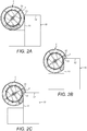
FIGS. 2A to 2E show a chamber of the wheel assembly ofFIG. 1 during use; -
FIGS. 3A to 3C show the wheel assembly ofFIG. 1 overcoming an obstacle during use; -
FIG. 4 shows a wheel assembly according to another embodiment of the invention; -
FIG. 5 shows a wheel assembly according to another embodiment of the invention; -
FIG. 6 shows a wheel assembly according to another embodiment of the invention; -
FIG. 7 shows a vehicle that includes the wheel assembly; and, -
FIG. 8 shows a wheelchair that includes the wheel assembly. - An embodiment of a
wheel assembly 1 according to the invention is illustrated byFIG. 1 . Thewheel assembly 1 comprises a wheel that is formed of ahub 2 and arim 3 concentrically mounted to thehub 2 by a connectingwall 4. In the embodiments illustrated byFIGS. 1 to 6 , the connectingwall 4 comprises a number of spokes arranged between therim 3 and thehub 2; however other arrangements are equally feasible, for example a solid wheel, or a solid wheel in which cuts outs are made in the connectingwall 4 for lightness. In some examples, the wheel may be formed of a disc. - The illustrated
wheel assembly 1 is a drive wheel, meaning that torque is applied to thewheel assembly 1 to provide a driving force. In this example, theaxle 5 is a drive axle that is coupled to a motor or other drive means. The drive axle can be coupled to thehub 2 in a number of conventional means, for example a spine or key. However, it will be appreciated that in other examples the wheel may not be a drive wheel, for example the wheel may be a passive trailer wheel or a passive steering wheel. - It will be appreciated that the
wheel assembly 1 described herein may be used in a wide variety of different applications. For example, thewheel assembly 1 can be used on a vehicle. In one example, thewheel assembly 1 is used on a wheelchair. In other examples, thewheel assembly 1 is used on a mobility vehicle, for example a mobility scooter. In yet further examples thewheel assembly 1 is used on search and rescue vehicles and specialised off-road vehicles. Thewheel assembly 1 may be used on remotely controlled or autonomous vehicles, including space exploration vehicles or vehicles for exploring hazardous environments. - As illustrated, the wheel assembly of
FIG. 1 further comprises fourchambers 6 arranged about the circumference of therim 3. Eachchamber 6 is enclosed by a continuousflexible wall 7 that forms a closed endedelongate tube 8. Eachtube 8 is arranged about a discrete portion of therim 3 and is closely spaced to anadjacent tube 8 so that the fourtubes 8 defining the fourchambers 6 provide full coverage of therim 3. - The
chambers 6 are coupled to therim 3 such that torque can be transferred between therim 3 and theflexible wall 7. For example, it is envisaged that theflexible wall 7 may be adhered, welded or otherwise attached to an outer surface of therim 3. To further assist the transfer of torque, supportingfins 9 can optionally be provided betweenadjacent chambers 6. Eachfin 9 extends radially outward of therim 3 to provide a surface against which a portion of theflexible wall 7 is supported, that is, the portion ofwall 7 defining one of the longitudinal ends of therespective tube 8. Therefore, as thewheel 1 is caused to rotate, torque is transferred from thehub 2 to each of the supportingfins 9 and, in turn, to eachflexible wall 7 of eachrespective chamber 6. - Each
chamber 6 is filled with atransition substance 15 that is configured to transform from a fluid state that allows thechamber 6 to deform, and a rigid state that maintains thechamber 6 in its deformed state. Therefore, during use, as thewheel assembly 1 encounters an obstacle achamber 6 can be deformed while thetransition substance 15 is in a fluid state. Then, thetransition substance 15 can be transformed to its rigid state to maintain thechamber 6 in its deformed shape. This can provide increased purchase on the obstacle, allowing thewheel assembly 1 to more easily overcome the obstacle. Anactuator 14 is provided to effect transformation of thetransition substance 15 between the fluid state and the rigid state, as explained further hereinafter. - In normal use, as the
wheel 1 rolls along a flat surface, thetransition substance 15 is in the fluid state. This allows thewheel 1 to provide a degree of compliancy over irregularities in the surface by displacement of theflexible wall 7, providing traction and shock absorption. - As illustrated by
FIGS. 2A to 2E , the wheel is described overcoming astep 10, such as a kerb. Thestep 10 has vertical 11 andhorizontal faces 12 that are adjoined by anedge 13. Thestep 10 has a height that is slightly greater than one half of the diameter of the wheel, meaning that conventional wheels will struggle to overcome thisstep 10. - In a first stage of operation of the
wheel assembly 1, shown inFIGS. 2A to 2B , thetransition 15 substance is in the fluid state. Thewheel assembly 1 rolls up against thestep 10 so that theflexible wall 7 of thechamber 6 adjacent thestep 10 conforms around theedge 13 of thestep 10. As shown inFIG. 2B , in the conformed state thechamber 6 has deformed about theedge 13 such that a part of thechamber 6 overlies thehorizontal face 12 of the step. The deformed shape of thechamber 6 is referred to as a conformal shape. - In a second stage of operation, shown in
FIGS. 2C to 2D , theactuator 14 is activated and thetransition substance 15 is made rigid so as to prevent further deformation of theflexible wall 7 and maintain thechamber 6 in its conformal shape. The deformedflexible wall 7 then effectively acts as a grouser, allowing the portion of theflexible wall 7 in contact with thehorizontal face 12 of thestep 10 to provide purchase on thestep 10 as thewheel 1 is rotated. Thewheel assembly 1 may then roll over theedge 13 of thestep 10 and onto thehorizontal face 12 with reduced risk of slippage. - In a third stage of operation, shown in
FIG. 2E , theactuator 14 restores thetransition substance 15 to its fluid state allowing theflexible wall 7 to take up its natural shape for normal operation. - A first example of the
actuator 14 andtransition substance 15 will be described with reference toFIGS. 3A to 3C . These FIGS. illustrate onechamber 6 of thewheel assembly 1 described with reference toFIG. 1 to FIG. 2E . - In the embodiment of
FIGS. 3A-3C , thetransition substance 15 comprises jammingparticles 19 and aninterstitial gas 20. This embodiment relies on the principle of jamming transition to effect the change between the fluid state and the rigid state, whereby theinterstitial gas 20 is evacuated to lock the jammingparticles 19 together in the rigid state within thechamber 6. - As shown in
FIG. 3A thechamber 6 is filled withinterstitial gas 20. Before thewheel assembly 1 encounters an obstacle the compressibility of thegas 20 and flexibility of theflexible wall 7 allows thechamber 6 to conform to the shape of the obstacle. As shown inFIG. 3B , as thechamber 6 comes into contact with the obstacle theflexible wall 7 deforms, allowing thechamber 6 to conform to the shape of the obstacle. Then, as shown inFIG. 3C , thegas 20 is evacuated from thechamber 6, which draws theflexible wall 7 around the jammingparticles 19 locking them together so that theflexible wall 7 is rigidified in the deformed state and thechamber 6 is maintained in its conformal state. Therigidified chamber 6 provides increased purchase between thewheel assembly 1 and the obstacle, allowing the wheel to overcome the obstacle as described previously. - As illustrated in
FIG. 4 , theactuator 14 comprises apump 22 for evacuating theinterstitial gas 20 from thechambers 6. Avalve 21 is provided between the pump and eachchamber 6. Thevalve 21 may be opened and closed by theactuator 14. Thepump 22 can either be mounted to thewheel 1, as shown, or can be mounted to the vehicle to which thewheel 1 is attached. - To evacuate the
interstitial gas 20 thepump 22 is operated until the pressure inside thechamber 6 falls below a threshold level which is below atmospheric pressure. Thevalve 21 is then closed and the pressure level inside thechamber 6 is maintained. Atmospheric pressure outside thechamber 6 presses theflexible wall 7 against the jammingparticles 19, causing them to interlock so that theflexible wall 7 is rigidified. Ideally theflexible wall 7 has some elasticity to minimise the number of folds that form in thewall 7 as the volume of thechamber 6 is reduced. - Preferably, the
pump 22 may be reversible in order to restore thetransition substance 15 to the fluid state by pumping gas back into thechamber 6. In this case, thevalve 21 is opened, thepump 22 is activated and thechamber 6 is inflated, whereupon thevalve 21 is again closed to maintain thechamber 6 in its inflated state. Alternatively, as illustrated, areservoir 23 is provided to store gas that has been removed from thechamber 6. In this case, thepump 22 is operated to deflate thechamber 6 by pumping gas from thechamber 6 into thereservoir 23, whereupon thevalve 21 is closed to both retain the gas in thereservoir 23 and to maintain the pressure level in thechamber 6. In order to restore thetransition substance 15 to the fluid state thevalve 21 is opened and the gas moves back into thechamber 6. - In an alternative example, the
interstitial gas 20 is evacuated from thechamber 6 as a result of the pressure applied to thechamber 6 during deformation and/or due to the elastic tension in theflexible wall 7. In these examples, when thevalve 21 is opened the volume of thechamber 6 is reduced, forcing out thegas 20. The elastic tension of thewall 7 compresses together the jammingparticles 19 causing them to interlock so that theflexible wall 7 is rigidified. A pump may be provided to inflate thechamber 6 once the obstacle has been overcome. - In a further alternative example,
gas 20 can be moved back into thechamber 6 by providing a biasing member that re-inflates the reservoir. For example, the chamber may include an elastic member that is compressed as thegas 20 is evacuated, and once thevalve 21 is re-opened the biasing member urges theflexible wall 7 into its inflated state, drawinggas 20 through thevalve 21 and into thechamber 6. - In examples, the jamming particles of the
transition substance 15 may be small individual granules or grains made from any type of metallic, polymer, or other material. In some examples, the jamming particles may be a ground material, for example coffee grounds, ground glass, sand, rice, sawdust, crushed nut shells, oats, cornmeal, salt, seeds. In a preferred example, the jamming particles are small metallic balls, for example ball bearings. In another preferred example, the jamming particles are small plastic beads. In a preferred example, the interstitial gas of thetransition substance 15 is air. However, the interstitial gas may be another gas, for example nitrogen, carbon dioxide, or other gas. - In another embodiment of the invention shown in
FIG. 5 , in which like features retain the same reference numbers, thetransition substance 15 comprises a magnetorheological fluid and theactuator 14 comprises anelectromagnet 24. The magnetorheological fluid is configured to change viscosity in response to a magnetic field. The viscosity of the fluid is variable depending on the strength of the magnetic field applied, with an increase in the magnetic field strength causing a corresponding increase in viscosity. In order to transform the magnetorheological fluid from the fluid state to the rigid state, electric power is provided to theelectromagnet 24 to generate the magnetic field. The electric power and the corresponding magnetic field strength are great enough to ensure that the magnetorheological fluid is effectively rigid, which maintains theflexible wall 7 andchamber 6 in the conformal state. The fluid state is restored by deactivation of theelectromagnet 24 and removal of the magnetic field. - The wheel assembly may include one or
more electromagnets 24 perchamber 6. For example, one, two, three or fourelectromagnets 24 may be required for eachchamber 6. - The magnetorheological fluid may be substantially incompressible. Therefore, in order for the
flexible wall 7 to conform to an object during the first stage of operation of thewheel 1, theflexible wall 7 is made from a stretchable, elastic material. This ensures that a portion of theflexible wall 7 may conform to the obstacle. - In examples, the magnetorheological fluid of the
transition substance 15 comprises a carrier oil and magnetic particles suspended in the carrier fluid, such as oil or water. The magnetorheological fluid optionally further includes a surfactant to prevent settling of the magnetic particles within the carrier fluid. Examples of suitable carrier fluids include silicon oils, mineral oils, paraffin oils, silicone copolymers, white oils, hydraulic oils, synthetic hydrocarbon oil, water, esterified fatty acid, or ferrofluid . Examples of the magnetic particles may include pure iron, iron alloys (incl. cobalt, vanadium manganese, molybdenum, silicon, nickel), carbonyl iron, atomized iron, water-atomized iron, iron oxides (incl. Fe2O3, Fe3O4), low carbon steel grades, silicon steel, nickel, cobalt, ferritic stainless steel, atomized stainless steel, and the like. - In yet another example, similar to the magnetorheological fluid example of
FIG. 5 , thetransition substance 15 comprises an electrorheological fluid and theactuator 14 is configured to generate an electric field. The viscosity of the electrorheological fluid is increased by applying an electric filed to the electrorheological fluid. Therefore, theelectrorheological transition substance 15 can be transformed between the fluid state and the rigid state. - Preferably, the electrorheological fluid comprises a suspension of fine semi-conducting particles in an electrically-insulating fluid, for example silicone oil.
- In other examples, the
transition substance 15 may comprise an electrorheological elastomer, and theactuator 14 may be configured to generate an electric and/or magnetic field that alters the stiffness of the electrorheological elastomer.
For example, the electrorheological elastomer may comprise a flexible silicon or rubber material with magnetic and/or charged particles distributed through the material. In this way, a magnetic and/or electric field can be used to control the stiffness of the electrorheological elastomer. - In preferred examples, the
wheel assembly 1 described above with reference to any ofFIGS. 1 to 5 further includes a processor configured to control theactuator 14 to transform the transition substance between the fluid and rigid states. Thewheel assembly 1 may also include one or more sensors. For example, asensor 16 may be configured to detect deformation of thechamber 6, such that the processor is able to determine when to operateactuator 14. In another example, a sensor may be provided to detect when thewheel assembly 1 is approaching an obstacle, and/or when thewheel assembly 1 is in contact with an obstacle to determine when to operateactuator 14. - A
suitable connection 17 is provided to relay signals between thesensor 16, processor andactuator 14, for example a controlled area network, 12 C or RS232 are all viable options amongst others. For practical purposes the processor may be located within thehub 2. - In examples where the
transition substance 15 comprises jamming particles and an interstitial gas, as described with reference toFIGS. 3A to 3C , thesensor 16 is apressure sensor 16 configured to measure the pressure inside thechamber 6. In this way, during the first stage of operation as theflexible wall 7 conforms to the obstacle, the pressure inside thechamber 6 increases and is measured by thesensor 16. Thepressure sensor 16 thereby generates a signal which varies in proportion to the deformation of thechamber 6. The signal is relayed to the processor which is configured to activate theactuator 14 when the pressure level increases above a threshold value in order to cause thetransition substance 15 to transform from the fluid state to the rigid state. As theactuator 14 evacuates theinterstitial gas 20 from thechamber 6, the pressure in thechamber 6 drops. When the pressure level drops below a threshold value, the processor may then activate thelockable valve 21 to retain theflexible wall 7 in the rigid state. - Such a
pressure sensor 16 may also be used with examples where thetransition substance 15 is a rheological fluid, either a magnetorheological fluid or an electrorheological fluid, as described above. In these examples, as thechamber 6 is deformed the internal pressure will increase, which can be detected by apressure sensor 16, and theactuator 14 can transform thetransition substance 15 from the fluid to the liquid state once a threshold pressure has been reached. - Alternatively, in an unillustrated example, the
sensor 16 may be a deformation sensor that detects the deformation of thechamber 6 of any of the above-described examples. For example, the sensor may be an optical sensor, for example a camera, which is positioned on thewheel assembly 1 or vehicle and visually detects engagement between thewheel assembly 1 and obstacles. In other examples, thesensor 16 may be a physical pressure sensor, for example a piezo electric sensor, arranged to detect engagement between thewheel assembly 1 and obstacles. In other examples, the sensor may be a proximity sensor arranged to detect when one part of theflexible wall 7 is proximate to another part, thereby determining deformation of thechamber 6. In each case, the processor is configured to operate theactuator 14 in dependence on the detected obstacle or deformation. - In further examples, the wheel assembly may include an angular position sensor configured to generate a signal indicative of the part of the
wheel assembly 1, in particular whichchamber 6 on thewheel assembly 1, is in contact with the obstacle. This angular wheel position may be used by the processor to determine whichchamber 6 has been deformed, and therefore whichchamber 6 to transform from the fluid state to the rigid state. Thesensor 16 can also be used to determine when to change thetransition substance 15 from the rigid state to the fluid state after an obstacle has been overcome. - In further examples, the
wheel assembly 1 of any of the above-described examples may additionally comprise acompressible layer 18 that extends around therim 3. In this embodiment, thechambers 6 are arranged around thecompressible layer 18. Thecompressible layer 18 is preferably formed from a pneumatic bladder, but could alternatively be a compressible material such as rubber. Thecompressible layer 18 spaces thechambers 6 from therim 3 of thewheel 1. This allows localised areas of achamber 6 to be displaced into thecompressible layer 18 during deformation, and once thetransition substance 15 is rigidified thecompressible layer 18 will be held in a deformed state. This in turn provides theflexible wall 7 with a greater range of movement for a givenchamber 6 size, increasing the size of the contact patch between theflexible wall 7 and the obstacle. - As shown in
FIGS. 1 to 6 , thewheel assembly 1 may further comprise an outerflexible tread 25 that extends around thewheel 1 outward of thechambers 6, so as to be contactable with the ground during use. The flexibility of thetread 25 allows thetread 25 to conform to the shape of an obstacle with thechamber 6 underneath. Thetread 25 may be made from any high friction material and may further comprise a tread pattern to assist with water displacement and/or for increased traction on soft surfaces. In a preferred embodiment, thetread 25 is made from a synthetic rubber. In another example, thetread 25 is made from a flexible metal and includes grousers for increasing traction. In another embodiment, thetread 25 is a tyre casing that extends around the sides of thechambers 6 and into contact with therim 3 to completely enclose thechambers 6. - The
tread 25 may be adhered to theflexible wall 7 of thechambers 6 using a suitable adhesive or welding technique. In embodiments where thetread 25 extends into contact with therim 3, thetread 25 may grip therim 3 by cooperation of flange portions (not shown) on therim 3 and a corresponding lip on edges of thetread 25. - In the above described embodiments the
wheel assembly 1 comprises fourchambers 6. However, the invention is not limited to fourchambers 6 and any appropriate number ofchambers 6 is envisaged. For example, in a simplified embodiment, asingle chamber 6 is provided that extends about theentire rim 3. In other examples, thewheel assembly 1 includes 2 chambers, 3 chambers, 5 chambers, 6 chambers or more. - A greater number of
chambers 6 might be provided for greater control over discrete portions of thewheel 1. Therefore, wheels with a larger circumference will includemore chambers 6. Increasing the number ofchambers 6 in this way can allow two or more portions of thewheel 1 occupied byindividual chambers 6 to respond separately to complex obstacles, or when obstacles are immediately adjacent one another, such as adjacent steps along a flight of stairs. In this instance theflexible wall 7 of onechamber 6 may rigidify about the first step while theflexible wall 7 of theadjacent chamber 6 conforms to the second step. - Further, a
wheel 1 that is wider in an axial direction may have two ormore chambers 6 positioned side by side so as to cover the full width of thewheel 1. -
FIG. 7 shows avehicle 26 that includes several of thewheels 1 described above. In particular,FIG. 7 illustrates a rover vehicle, which may be remotely controlled or autonomous. Thevehicle 26 includes thewheels 1 in the front and rear, but it will be appreciated that thewheels 1 may be used only on the front, or only on the rear.FIG. 7 also illustrates thevehicle 26 climbing astep 10. Such avehicle 26 may be used in search and rescue, defence applications, or industrial applications. Alternatively, such avehicle 26 may be used for exploration. -
FIG. 8 shows awheelchair 27 that includes several of thewheels 1 described above. The wheelchair may include a motor for driving at least one of thewheels 1, for example the rear wheels. Thewheelchair 27 includes thewheels 1 in the front and rear, but it will be appreciated that thewheels 1 may be used only on the front, or only on the rear.FIG. 8 also illustrates thewheelchair 27 climbing a series ofsteps 28. In addition, thewheels 1 described above may be used on other mobility vehicles, for example a wheeled-walker or a mobility scooter. - It will be appreciated that the foregoing description is given by way of example only and that modifications may be made to the wheel assembly of the present invention without departing from the scope of the appended claims.
Claims (15)
- A wheel assembly (1) comprising:a wheel, the wheel having a hub (2) and a rim (3) concentrically mounted to the hub (2);a plurality of deformable chambers (6) disposed outwardly of the rim, each chamber (6) extending about a discreet portion of the wheel and containing a transition substance (15); andan actuator (14) configured to transform the transition substance (15) within each chamber (6) between:a fluid state in which the deformable chamber (6) can deform into a conformal state as the wheel encounters an obstacle during use; and,a rigid state in which the transition substance (15) is rigidified to maintain the deformable chamber (6) in said conformal state to provide increased purchase on said obstacle.
- A wheel assembly according to claim 1, comprising four deformable chambers (6).
- A wheel assembly according to claim 2, wherein the actuator (14) is configured to selectively operate the transition substance (15) within each deformable chamber (6) independently of the transition substance (15) within any other deformable chamber (6).
- A wheel assembly according to any preceding claim, wherein the wheel further comprises a plurality of supporting fins (9) extending radially between adjacent deformable chambers (6).
- A wheel assembly according to any preceding claim, wherein the wheel further comprises a compressible layer (18) disposed between the deformable chamber (6) and the rim (3), and wherein the compressible layer (18) preferably comprises a pneumatic bladder.
- A wheel assembly according to any preceding claim, further comprising:a sensor (16) arranged to detect deformation of the deformable chambers (6); and/ora sensor arranged to detect the presence of an obstacle.
- A wheel assembly according to claim 6, wherein the actuator is configured to transform the transition substance between the fluid state and the rigid state in response to a signal generated by the sensor (16).
- A wheel assembly according to any preceding claim, wherein the transition substance (15) comprises jamming particles (19) and an interstitial gas (20), and wherein the actuator (14) is configured to evacuate the interstitial gas (20) from the deformable chamber (6) to transform the transition substance (15) from the fluid state to the rigid state, and wherein the actuator (14) is further configured to move gas into the deformable chamber (6) to transform the transition substance (15) from the rigid state to the fluid state after said obstacle has been overcome.
- A wheel assembly according to claim 8, wherein the deformable chamber (6) comprises a self-inflation mechanism, said self-inflation mechanism preferably comprising a biasing member.
- A wheel assembly according to any of claims 1 to 7, wherein the transition substance (15) comprises a rheological substance and the actuator (14) is configured to alter the viscosity of the rheological substance
- A wheel assembly according to claim 10, wherein the rheological substance is a magnetorheological fluid and the actuator (14) comprises an electromagnet.
- A wheel assembly according to claim 10, wherein the rheological substance is an electrorheological fluid and the actuator (14) is configured to generate an electric field.
- A wheel assembly according to claim 10, wherein the rheological substance is an electrorheological elastomer and the actuator (14) is configured to generate an electric and/or magnetic field.
- A vehicle (26) comprising at least one wheel assembly (1) according to any preceding claim.
- A wheelchair (27) comprising at least one wheel assembly (1) according to any of claims 1 to 13.
Applications Claiming Priority (2)
| Application Number | Priority Date | Filing Date | Title |
|---|---|---|---|
| GBGB1621681.4A GB201621681D0 (en) | 2016-12-20 | 2016-12-20 | Wheel assembly |
| PCT/EP2017/081994 WO2018114389A1 (en) | 2016-12-20 | 2017-12-08 | Wheel assembly |
Publications (2)
| Publication Number | Publication Date |
|---|---|
| EP3558697A1 EP3558697A1 (en) | 2019-10-30 |
| EP3558697B1 true EP3558697B1 (en) | 2020-09-23 |
Family
ID=58284325
Family Applications (2)
| Application Number | Title | Priority Date | Filing Date |
|---|---|---|---|
| EP17829615.8A Active EP3558698B1 (en) | 2016-12-20 | 2017-12-08 | Wheel assembly |
| EP17811946.7A Active EP3558697B1 (en) | 2016-12-20 | 2017-12-08 | Wheel assembly |
Family Applications Before (1)
| Application Number | Title | Priority Date | Filing Date |
|---|---|---|---|
| EP17829615.8A Active EP3558698B1 (en) | 2016-12-20 | 2017-12-08 | Wheel assembly |
Country Status (6)
| Country | Link |
|---|---|
| US (2) | US20200086682A1 (en) |
| EP (2) | EP3558698B1 (en) |
| CN (2) | CN110087898B (en) |
| ES (2) | ES2837849T3 (en) |
| GB (1) | GB201621681D0 (en) |
| WO (2) | WO2018114389A1 (en) |
Families Citing this family (12)
| Publication number | Priority date | Publication date | Assignee | Title |
|---|---|---|---|---|
| GB201621681D0 (en) * | 2016-12-20 | 2017-02-01 | Airbus Defence & Space Ltd | Wheel assembly |
| IT201800002050A1 (en) * | 2018-01-26 | 2019-07-26 | Andrea Belli | Rotates with movable elements |
| CN109050155A (en) * | 2018-07-30 | 2018-12-21 | 北京科技大学 | A kind of flexible vehicle wheel of adaptive rough ground |
| CN111568068B (en) * | 2020-04-29 | 2022-04-08 | 湖南德荣医疗健康产业有限公司 | Indoor transportation robot for medical consumables |
| WO2022126289A1 (en) * | 2020-12-17 | 2022-06-23 | Universidad Diego Portales | Wheelchair with wheels that can adapt to the surface to be travelled over. |
| CN112957185B (en) * | 2021-02-01 | 2022-02-22 | 吉林大学 | Rehabilitation wheelchair with lower limb massage function |
| CN113183680A (en) * | 2021-04-30 | 2021-07-30 | 中国矿业大学 | An automatic obstacle clearance device for a mine inspection robot |
| CN113401248B (en) * | 2021-06-29 | 2022-04-12 | 中国建筑第八工程局有限公司 | Large-scale pipeline transport means in narrow and small space in utility tunnel |
| CN114312148B (en) * | 2021-12-14 | 2023-10-27 | 吉林大学 | A metal flexible tread inflatable planetary wheel and planetary car |
| WO2023129861A1 (en) * | 2021-12-28 | 2023-07-06 | Bridgestone Americas Tire Operations, Llc | System, method, and apparatus for maintaining a tire inflation pressure |
| CN115489636A (en) * | 2022-11-01 | 2022-12-20 | 南京信息工程大学 | Deformable spoke wheel mechanism |
| KR102923862B1 (en) * | 2024-03-15 | 2026-02-04 | 박재용 | Shock absorbing wheel structure |
Family Cites Families (30)
| Publication number | Priority date | Publication date | Assignee | Title |
|---|---|---|---|---|
| US2253230A (en) * | 1940-03-07 | 1941-08-19 | Feldman Isaiah | Safety inner tube for pneumatic tires |
| US3256123A (en) * | 1962-05-28 | 1966-06-14 | Frank A Hart | Automobile tire |
| ES2017884A6 (en) | 1989-12-07 | 1991-03-01 | Belil Creixell Jose Luis | Pneumatic tube for vehicle wheels and the like. |
| US6725895B1 (en) * | 1998-11-23 | 2004-04-27 | Michael Tsipov | Wheel |
| DE29906660U1 (en) * | 1999-04-15 | 1999-07-15 | Strothmann, Eckhard, 33790 Halle | Pneumatic vehicle tires |
| JP3910001B2 (en) * | 1999-05-27 | 2007-04-25 | トピー工業株式会社 | Wheel with damper for automobile and manufacturing method thereof |
| FR2795947A1 (en) * | 1999-07-05 | 2001-01-12 | Alain Limpas | Wheelchair has deformable rims on large wheels for overcoming obstacles such as sidewalks or steps |
| DE10002611A1 (en) * | 2000-01-22 | 2001-08-02 | Steinert Manfred | Vehicle tire resisting effects of puncturing, has three or more air chambers distributed around its internal circumference |
| US6701985B2 (en) * | 2002-05-20 | 2004-03-09 | Brian A. Russell | Energy return wheel systems and methods |
| KR100448463B1 (en) | 2002-06-20 | 2004-09-13 | 한국타이어 주식회사 | Strength Control Structure of Tire |
| US20040112495A1 (en) * | 2002-12-09 | 2004-06-17 | Curtis Arlen Weise | Self inflating tire |
| CN1666889A (en) * | 2004-03-10 | 2005-09-14 | 翁悦红 | High-elastic energy-saving force reverberatory wheel |
| US7380618B2 (en) * | 2005-02-22 | 2008-06-03 | Gamma Two, Inc. | Stair climbing platform apparatus and method |
| JP2006335258A (en) * | 2005-06-03 | 2006-12-14 | Daiwarashi Co Ltd | Caster |
| JP2008018206A (en) | 2006-07-11 | 2008-01-31 | Hiroyuki Ogura | Stair-climbing wheelchair with low-pressure tires |
| CN101513819B (en) * | 2009-03-12 | 2012-03-21 | 昆明理工大学 | Sleeved resilience damping wheel |
| CN201380718Y (en) * | 2009-03-12 | 2010-01-13 | 昆明理工大学 | Outer shell energy recovery wheels |
| DE102009052253A1 (en) | 2009-11-06 | 2011-05-12 | Manfred Hoffmann | Wheelchair for climbing e.g. spiral stairs, has running surface whose segment lies in direct proximity to step edge such that ends of pressure springs are connected with surface and placed on nearest level during rotation of rear wheels |
| KR101116869B1 (en) | 2009-12-02 | 2012-03-06 | 한국타이어 주식회사 | Magnetorheological non pneumatic tire |
| CN101875284B (en) * | 2009-12-07 | 2013-08-21 | 中国北方车辆研究所 | Deformable wheel device |
| GB201010939D0 (en) * | 2010-06-29 | 2010-08-11 | Hall Gregory | Tyre assembly |
| CN102120402A (en) * | 2011-02-20 | 2011-07-13 | 胡盼成 | Metal spring tire |
| US8678054B2 (en) * | 2011-03-01 | 2014-03-25 | Scennco, Inc. | Segmented tire apparatus |
| WO2012153170A1 (en) * | 2011-05-11 | 2012-11-15 | Softwheel Ltd. | Selective wheel suspension system |
| US20130167991A1 (en) * | 2011-12-29 | 2013-07-04 | Patrick Timothy Donohue | Terrain Resilient Wheel Maintaining a Uniform Elevation |
| US9266389B2 (en) * | 2013-07-19 | 2016-02-23 | The Boeing Company | Wheel system for a vehicle |
| CN104417271A (en) * | 2013-08-26 | 2015-03-18 | 陕西胜慧源信息科技有限公司 | Novel inflation-free tire |
| US20160159213A1 (en) * | 2014-12-05 | 2016-06-09 | GM Global Technology Operations LLC | Hybrid electric ground mobility system |
| CN105599536B (en) * | 2016-03-08 | 2018-03-20 | 武汉理工大学 | A kind of variable-diameter hub for vehicle wheel |
| GB201621681D0 (en) * | 2016-12-20 | 2017-02-01 | Airbus Defence & Space Ltd | Wheel assembly |
-
2016
- 2016-12-20 GB GBGB1621681.4A patent/GB201621681D0/en not_active Ceased
-
2017
- 2017-12-08 US US16/471,279 patent/US20200086682A1/en not_active Abandoned
- 2017-12-08 WO PCT/EP2017/081994 patent/WO2018114389A1/en not_active Ceased
- 2017-12-08 ES ES17829615T patent/ES2837849T3/en active Active
- 2017-12-08 CN CN201780079027.6A patent/CN110087898B/en active Active
- 2017-12-08 WO PCT/EP2017/082000 patent/WO2018114391A1/en not_active Ceased
- 2017-12-08 CN CN201780079024.2A patent/CN110087897B/en active Active
- 2017-12-08 ES ES17811946T patent/ES2834893T3/en active Active
- 2017-12-08 EP EP17829615.8A patent/EP3558698B1/en active Active
- 2017-12-08 US US16/471,281 patent/US11602955B2/en active Active
- 2017-12-08 EP EP17811946.7A patent/EP3558697B1/en active Active
Non-Patent Citations (1)
| Title |
|---|
| None * |
Also Published As
| Publication number | Publication date |
|---|---|
| EP3558698B1 (en) | 2020-09-23 |
| GB201621681D0 (en) | 2017-02-01 |
| CN110087897A (en) | 2019-08-02 |
| EP3558697A1 (en) | 2019-10-30 |
| CN110087898A (en) | 2019-08-02 |
| ES2837849T3 (en) | 2021-07-01 |
| US20200086688A1 (en) | 2020-03-19 |
| CN110087898B (en) | 2022-07-08 |
| WO2018114389A1 (en) | 2018-06-28 |
| ES2834893T3 (en) | 2021-06-21 |
| CN110087897B (en) | 2022-08-30 |
| WO2018114391A1 (en) | 2018-06-28 |
| US20200086682A1 (en) | 2020-03-19 |
| US11602955B2 (en) | 2023-03-14 |
| EP3558698A1 (en) | 2019-10-30 |
Similar Documents
| Publication | Publication Date | Title |
|---|---|---|
| EP3558697B1 (en) | Wheel assembly | |
| CN109689480B (en) | Drive module | |
| US8276701B2 (en) | Omni-directional contiguous moving surface | |
| US20110272254A1 (en) | Variable Compliance Wheel | |
| KR20010052261A (en) | Earth-based vehicle | |
| US8899104B2 (en) | Tire and method of selectively altering or controlling properties or characteristics thereof under varying conditions | |
| WO2008142679A2 (en) | Tire inflation system | |
| AU2022346655B2 (en) | Ad hoc tyre pressure control assembly | |
| AU760763B2 (en) | Low pressure tire | |
| US20120055599A1 (en) | Safety system for vehicle tire blowout | |
| EP3022068A1 (en) | A tyre with adjustable properties | |
| RU167698U1 (en) | VEHICLE WHEEL | |
| US8336912B2 (en) | Systems for and methods of facilitating a lateral maneuver by a vehicle | |
| WO2017077304A1 (en) | Device and method for transporting air between an air source of a vehicle and a tyre valve | |
| WO2007001246A1 (en) | Variable radial and/or lateral compliance wheel | |
| US4037679A (en) | Selective drive for truck dead axle | |
| RU2457117C1 (en) | Wheel with retractable studs | |
| US11458761B2 (en) | Traction system for vehicle | |
| RU2803432C1 (en) | Device for increasing traffic of wheeled machine equipped with air pressure regulation in tires | |
| RU2745724C2 (en) | Roller vehicle | |
| Odedra et al. | Towards solving the mobility issues of unmanned ground vehicles | |
| JP2501998Y2 (en) | Land vehicles used on soft or irregular support surfaces | |
| SK742008A3 (en) | Wheel with interchangeable parts of a tire rim with a variable width, and integrated anti-slip device in non-inflatable tire | |
| CA1071269A (en) | Selective drive for truck dead axle | |
| CN109720154A (en) | A kind of large-sized truck road trouble-proof tire against pressure |
Legal Events
| Date | Code | Title | Description |
|---|---|---|---|
| STAA | Information on the status of an ep patent application or granted ep patent |
Free format text: STATUS: UNKNOWN |
|
| STAA | Information on the status of an ep patent application or granted ep patent |
Free format text: STATUS: THE INTERNATIONAL PUBLICATION HAS BEEN MADE |
|
| PUAI | Public reference made under article 153(3) epc to a published international application that has entered the european phase |
Free format text: ORIGINAL CODE: 0009012 |
|
| STAA | Information on the status of an ep patent application or granted ep patent |
Free format text: STATUS: REQUEST FOR EXAMINATION WAS MADE |
|
| 17P | Request for examination filed |
Effective date: 20190625 |
|
| AK | Designated contracting states |
Kind code of ref document: A1 Designated state(s): AL AT BE BG CH CY CZ DE DK EE ES FI FR GB GR HR HU IE IS IT LI LT LU LV MC MK MT NL NO PL PT RO RS SE SI SK SM TR |
|
| AX | Request for extension of the european patent |
Extension state: BA ME |
|
| DAV | Request for validation of the european patent (deleted) | ||
| DAX | Request for extension of the european patent (deleted) | ||
| GRAP | Despatch of communication of intention to grant a patent |
Free format text: ORIGINAL CODE: EPIDOSNIGR1 |
|
| STAA | Information on the status of an ep patent application or granted ep patent |
Free format text: STATUS: GRANT OF PATENT IS INTENDED |
|
| INTG | Intention to grant announced |
Effective date: 20200618 |
|
| GRAS | Grant fee paid |
Free format text: ORIGINAL CODE: EPIDOSNIGR3 |
|
| GRAA | (expected) grant |
Free format text: ORIGINAL CODE: 0009210 |
|
| STAA | Information on the status of an ep patent application or granted ep patent |
Free format text: STATUS: THE PATENT HAS BEEN GRANTED |
|
| AK | Designated contracting states |
Kind code of ref document: B1 Designated state(s): AL AT BE BG CH CY CZ DE DK EE ES FI FR GB GR HR HU IE IS IT LI LT LU LV MC MK MT NL NO PL PT RO RS SE SI SK SM TR |
|
| REG | Reference to a national code |
Ref country code: GB Ref legal event code: FG4D |
|
| REG | Reference to a national code |
Ref country code: CH Ref legal event code: EP |
|
| REG | Reference to a national code |
Ref country code: DE Ref legal event code: R096 Ref document number: 602017024314 Country of ref document: DE |
|
| REG | Reference to a national code |
Ref country code: IE Ref legal event code: FG4D |
|
| REG | Reference to a national code |
Ref country code: AT Ref legal event code: REF Ref document number: 1316023 Country of ref document: AT Kind code of ref document: T Effective date: 20201015 |
|
| PG25 | Lapsed in a contracting state [announced via postgrant information from national office to epo] |
Ref country code: BG Free format text: LAPSE BECAUSE OF FAILURE TO SUBMIT A TRANSLATION OF THE DESCRIPTION OR TO PAY THE FEE WITHIN THE PRESCRIBED TIME-LIMIT Effective date: 20201223 Ref country code: HR Free format text: LAPSE BECAUSE OF FAILURE TO SUBMIT A TRANSLATION OF THE DESCRIPTION OR TO PAY THE FEE WITHIN THE PRESCRIBED TIME-LIMIT Effective date: 20200923 Ref country code: FI Free format text: LAPSE BECAUSE OF FAILURE TO SUBMIT A TRANSLATION OF THE DESCRIPTION OR TO PAY THE FEE WITHIN THE PRESCRIBED TIME-LIMIT Effective date: 20200923 Ref country code: GR Free format text: LAPSE BECAUSE OF FAILURE TO SUBMIT A TRANSLATION OF THE DESCRIPTION OR TO PAY THE FEE WITHIN THE PRESCRIBED TIME-LIMIT Effective date: 20201224 Ref country code: NO Free format text: LAPSE BECAUSE OF FAILURE TO SUBMIT A TRANSLATION OF THE DESCRIPTION OR TO PAY THE FEE WITHIN THE PRESCRIBED TIME-LIMIT Effective date: 20201223 Ref country code: SE Free format text: LAPSE BECAUSE OF FAILURE TO SUBMIT A TRANSLATION OF THE DESCRIPTION OR TO PAY THE FEE WITHIN THE PRESCRIBED TIME-LIMIT Effective date: 20200923 |
|
| REG | Reference to a national code |
Ref country code: AT Ref legal event code: MK05 Ref document number: 1316023 Country of ref document: AT Kind code of ref document: T Effective date: 20200923 |
|
| PG25 | Lapsed in a contracting state [announced via postgrant information from national office to epo] |
Ref country code: RS Free format text: LAPSE BECAUSE OF FAILURE TO SUBMIT A TRANSLATION OF THE DESCRIPTION OR TO PAY THE FEE WITHIN THE PRESCRIBED TIME-LIMIT Effective date: 20200923 Ref country code: LV Free format text: LAPSE BECAUSE OF FAILURE TO SUBMIT A TRANSLATION OF THE DESCRIPTION OR TO PAY THE FEE WITHIN THE PRESCRIBED TIME-LIMIT Effective date: 20200923 |
|
| REG | Reference to a national code |
Ref country code: NL Ref legal event code: MP Effective date: 20200923 |
|
| REG | Reference to a national code |
Ref country code: LT Ref legal event code: MG4D |
|
| PG25 | Lapsed in a contracting state [announced via postgrant information from national office to epo] |
Ref country code: LT Free format text: LAPSE BECAUSE OF FAILURE TO SUBMIT A TRANSLATION OF THE DESCRIPTION OR TO PAY THE FEE WITHIN THE PRESCRIBED TIME-LIMIT Effective date: 20200923 Ref country code: SM Free format text: LAPSE BECAUSE OF FAILURE TO SUBMIT A TRANSLATION OF THE DESCRIPTION OR TO PAY THE FEE WITHIN THE PRESCRIBED TIME-LIMIT Effective date: 20200923 Ref country code: EE Free format text: LAPSE BECAUSE OF FAILURE TO SUBMIT A TRANSLATION OF THE DESCRIPTION OR TO PAY THE FEE WITHIN THE PRESCRIBED TIME-LIMIT Effective date: 20200923 Ref country code: RO Free format text: LAPSE BECAUSE OF FAILURE TO SUBMIT A TRANSLATION OF THE DESCRIPTION OR TO PAY THE FEE WITHIN THE PRESCRIBED TIME-LIMIT Effective date: 20200923 Ref country code: PT Free format text: LAPSE BECAUSE OF FAILURE TO SUBMIT A TRANSLATION OF THE DESCRIPTION OR TO PAY THE FEE WITHIN THE PRESCRIBED TIME-LIMIT Effective date: 20210125 Ref country code: CZ Free format text: LAPSE BECAUSE OF FAILURE TO SUBMIT A TRANSLATION OF THE DESCRIPTION OR TO PAY THE FEE WITHIN THE PRESCRIBED TIME-LIMIT Effective date: 20200923 |
|
| PG25 | Lapsed in a contracting state [announced via postgrant information from national office to epo] |
Ref country code: IS Free format text: LAPSE BECAUSE OF FAILURE TO SUBMIT A TRANSLATION OF THE DESCRIPTION OR TO PAY THE FEE WITHIN THE PRESCRIBED TIME-LIMIT Effective date: 20210123 Ref country code: PL Free format text: LAPSE BECAUSE OF FAILURE TO SUBMIT A TRANSLATION OF THE DESCRIPTION OR TO PAY THE FEE WITHIN THE PRESCRIBED TIME-LIMIT Effective date: 20200923 Ref country code: AL Free format text: LAPSE BECAUSE OF FAILURE TO SUBMIT A TRANSLATION OF THE DESCRIPTION OR TO PAY THE FEE WITHIN THE PRESCRIBED TIME-LIMIT Effective date: 20200923 Ref country code: AT Free format text: LAPSE BECAUSE OF FAILURE TO SUBMIT A TRANSLATION OF THE DESCRIPTION OR TO PAY THE FEE WITHIN THE PRESCRIBED TIME-LIMIT Effective date: 20200923 |
|
| REG | Reference to a national code |
Ref country code: ES Ref legal event code: FG2A Ref document number: 2834893 Country of ref document: ES Kind code of ref document: T3 Effective date: 20210621 |
|
| REG | Reference to a national code |
Ref country code: DE Ref legal event code: R097 Ref document number: 602017024314 Country of ref document: DE |
|
| PG25 | Lapsed in a contracting state [announced via postgrant information from national office to epo] |
Ref country code: SK Free format text: LAPSE BECAUSE OF FAILURE TO SUBMIT A TRANSLATION OF THE DESCRIPTION OR TO PAY THE FEE WITHIN THE PRESCRIBED TIME-LIMIT Effective date: 20200923 |
|
| PLBE | No opposition filed within time limit |
Free format text: ORIGINAL CODE: 0009261 |
|
| REG | Reference to a national code |
Ref country code: CH Ref legal event code: PL |
|
| STAA | Information on the status of an ep patent application or granted ep patent |
Free format text: STATUS: NO OPPOSITION FILED WITHIN TIME LIMIT |
|
| PG25 | Lapsed in a contracting state [announced via postgrant information from national office to epo] |
Ref country code: DK Free format text: LAPSE BECAUSE OF FAILURE TO SUBMIT A TRANSLATION OF THE DESCRIPTION OR TO PAY THE FEE WITHIN THE PRESCRIBED TIME-LIMIT Effective date: 20200923 Ref country code: SI Free format text: LAPSE BECAUSE OF FAILURE TO SUBMIT A TRANSLATION OF THE DESCRIPTION OR TO PAY THE FEE WITHIN THE PRESCRIBED TIME-LIMIT Effective date: 20200923 Ref country code: MC Free format text: LAPSE BECAUSE OF FAILURE TO SUBMIT A TRANSLATION OF THE DESCRIPTION OR TO PAY THE FEE WITHIN THE PRESCRIBED TIME-LIMIT Effective date: 20200923 |
|
| 26N | No opposition filed |
Effective date: 20210624 |
|
| REG | Reference to a national code |
Ref country code: BE Ref legal event code: MM Effective date: 20201231 |
|
| PG25 | Lapsed in a contracting state [announced via postgrant information from national office to epo] |
Ref country code: LU Free format text: LAPSE BECAUSE OF NON-PAYMENT OF DUE FEES Effective date: 20201208 Ref country code: IE Free format text: LAPSE BECAUSE OF NON-PAYMENT OF DUE FEES Effective date: 20201208 |
|
| PG25 | Lapsed in a contracting state [announced via postgrant information from national office to epo] |
Ref country code: CH Free format text: LAPSE BECAUSE OF NON-PAYMENT OF DUE FEES Effective date: 20201231 Ref country code: LI Free format text: LAPSE BECAUSE OF NON-PAYMENT OF DUE FEES Effective date: 20201231 |
|
| PG25 | Lapsed in a contracting state [announced via postgrant information from national office to epo] |
Ref country code: TR Free format text: LAPSE BECAUSE OF FAILURE TO SUBMIT A TRANSLATION OF THE DESCRIPTION OR TO PAY THE FEE WITHIN THE PRESCRIBED TIME-LIMIT Effective date: 20200923 Ref country code: MT Free format text: LAPSE BECAUSE OF FAILURE TO SUBMIT A TRANSLATION OF THE DESCRIPTION OR TO PAY THE FEE WITHIN THE PRESCRIBED TIME-LIMIT Effective date: 20200923 Ref country code: CY Free format text: LAPSE BECAUSE OF FAILURE TO SUBMIT A TRANSLATION OF THE DESCRIPTION OR TO PAY THE FEE WITHIN THE PRESCRIBED TIME-LIMIT Effective date: 20200923 |
|
| PG25 | Lapsed in a contracting state [announced via postgrant information from national office to epo] |
Ref country code: MK Free format text: LAPSE BECAUSE OF FAILURE TO SUBMIT A TRANSLATION OF THE DESCRIPTION OR TO PAY THE FEE WITHIN THE PRESCRIBED TIME-LIMIT Effective date: 20200923 |
|
| PG25 | Lapsed in a contracting state [announced via postgrant information from national office to epo] |
Ref country code: BE Free format text: LAPSE BECAUSE OF NON-PAYMENT OF DUE FEES Effective date: 20201231 |
|
| PG25 | Lapsed in a contracting state [announced via postgrant information from national office to epo] |
Ref country code: NL Free format text: LAPSE BECAUSE OF NON-PAYMENT OF DUE FEES Effective date: 20200923 |
|
| PGFP | Annual fee paid to national office [announced via postgrant information from national office to epo] |
Ref country code: DE Payment date: 20241210 Year of fee payment: 8 |
|
| PGFP | Annual fee paid to national office [announced via postgrant information from national office to epo] |
Ref country code: GB Payment date: 20241226 Year of fee payment: 8 |
|
| PGFP | Annual fee paid to national office [announced via postgrant information from national office to epo] |
Ref country code: FR Payment date: 20241224 Year of fee payment: 8 |
|
| PGFP | Annual fee paid to national office [announced via postgrant information from national office to epo] |
Ref country code: IT Payment date: 20241220 Year of fee payment: 8 |
|
| PGFP | Annual fee paid to national office [announced via postgrant information from national office to epo] |
Ref country code: ES Payment date: 20250131 Year of fee payment: 8 |