EP3558554B1 - A connection tube and its method of manufacturing - Google Patents
A connection tube and its method of manufacturing Download PDFInfo
- Publication number
- EP3558554B1 EP3558554B1 EP17823160.1A EP17823160A EP3558554B1 EP 3558554 B1 EP3558554 B1 EP 3558554B1 EP 17823160 A EP17823160 A EP 17823160A EP 3558554 B1 EP3558554 B1 EP 3558554B1
- Authority
- EP
- European Patent Office
- Prior art keywords
- alloy
- end portion
- annular
- tube
- connection tube
- Prior art date
- Legal status (The legal status is an assumption and is not a legal conclusion. Google has not performed a legal analysis and makes no representation as to the accuracy of the status listed.)
- Not-in-force
Links
Images

Classifications
-
- F—MECHANICAL ENGINEERING; LIGHTING; HEATING; WEAPONS; BLASTING
- F16—ENGINEERING ELEMENTS AND UNITS; GENERAL MEASURES FOR PRODUCING AND MAINTAINING EFFECTIVE FUNCTIONING OF MACHINES OR INSTALLATIONS; THERMAL INSULATION IN GENERAL
- F16L—PIPES; JOINTS OR FITTINGS FOR PIPES; SUPPORTS FOR PIPES, CABLES OR PROTECTIVE TUBING; MEANS FOR THERMAL INSULATION IN GENERAL
- F16L13/00—Non-disconnectable pipe joints, e.g. soldered, adhesive, or caulked joints
- F16L13/007—Non-disconnectable pipe joints, e.g. soldered, adhesive, or caulked joints specially adapted for joining pipes of dissimilar materials
-
- B—PERFORMING OPERATIONS; TRANSPORTING
- B21—MECHANICAL METAL-WORKING WITHOUT ESSENTIALLY REMOVING MATERIAL; PUNCHING METAL
- B21C—MANUFACTURE OF METAL SHEETS, WIRE, RODS, TUBES, PROFILES OR LIKE SEMI-MANUFACTURED PRODUCTS OTHERWISE THAN BY ROLLING; AUXILIARY OPERATIONS USED IN CONNECTION WITH METAL-WORKING WITHOUT ESSENTIALLY REMOVING MATERIAL
- B21C33/00—Feeding extrusion presses with metal to be extruded ; Loading the dummy block
- B21C33/004—Composite billet
-
- B—PERFORMING OPERATIONS; TRANSPORTING
- B21—MECHANICAL METAL-WORKING WITHOUT ESSENTIALLY REMOVING MATERIAL; PUNCHING METAL
- B21C—MANUFACTURE OF METAL SHEETS, WIRE, RODS, TUBES, PROFILES OR LIKE SEMI-MANUFACTURED PRODUCTS OTHERWISE THAN BY ROLLING; AUXILIARY OPERATIONS USED IN CONNECTION WITH METAL-WORKING WITHOUT ESSENTIALLY REMOVING MATERIAL
- B21C37/00—Manufacture of metal sheets, rods, wire, tubes, profiles or like semi-manufactured products, not otherwise provided for; Manufacture of tubes of special shape
- B21C37/06—Manufacture of metal sheets, rods, wire, tubes, profiles or like semi-manufactured products, not otherwise provided for; Manufacture of tubes of special shape of tubes or metal hoses; Combined procedures for making tubes, e.g. for making multi-wall tubes
-
- B—PERFORMING OPERATIONS; TRANSPORTING
- B21—MECHANICAL METAL-WORKING WITHOUT ESSENTIALLY REMOVING MATERIAL; PUNCHING METAL
- B21C—MANUFACTURE OF METAL SHEETS, WIRE, RODS, TUBES, PROFILES OR LIKE SEMI-MANUFACTURED PRODUCTS OTHERWISE THAN BY ROLLING; AUXILIARY OPERATIONS USED IN CONNECTION WITH METAL-WORKING WITHOUT ESSENTIALLY REMOVING MATERIAL
- B21C37/00—Manufacture of metal sheets, rods, wire, tubes, profiles or like semi-manufactured products, not otherwise provided for; Manufacture of tubes of special shape
- B21C37/06—Manufacture of metal sheets, rods, wire, tubes, profiles or like semi-manufactured products, not otherwise provided for; Manufacture of tubes of special shape of tubes or metal hoses; Combined procedures for making tubes, e.g. for making multi-wall tubes
- B21C37/15—Making tubes of special shape; Making tube fittings
- B21C37/154—Making multi-wall tubes
-
- B—PERFORMING OPERATIONS; TRANSPORTING
- B21—MECHANICAL METAL-WORKING WITHOUT ESSENTIALLY REMOVING MATERIAL; PUNCHING METAL
- B21D—WORKING OR PROCESSING OF SHEET METAL OR METAL TUBES, RODS OR PROFILES WITHOUT ESSENTIALLY REMOVING MATERIAL; PUNCHING METAL
- B21D39/00—Application of procedures in order to connect objects or parts, e.g. coating with sheet metal otherwise than by plating; Tube expanders
- B21D39/04—Application of procedures in order to connect objects or parts, e.g. coating with sheet metal otherwise than by plating; Tube expanders of tubes with tubes; of tubes with rods
Definitions
- connection tube for connecting two tubes according to the preamble of claim 1. It further relates to a method for manufacturing such a connection tube according to the preamble of claim 5, a method for connecting two tubes of different alloys, and a tubular product comprising a connection tube.
- tubes of different alloys For many industrial applications, there is a need to join tubes of different alloys and form a tubular product that is composed of several tube portions. This can be for example to save costs, since one part of a tube may be exposed to more demanding conditions than another part of the tube, which can therefore be made from a less expensive alloy. It may also be in order to tailor tubes that are likely to be subjected to demanding conditions varying along the tube, such as highly corrosive conditions along part of the tube and conditions requiring high mechanical strength along another part of the tube.
- GB1258141 which forms the basis for the preamble of claim 1, discloses a method for joining two tubes of different alloys that are difficult to join by welding.
- a connection tube is produced that has a first end portion of a first alloy, compatible with the alloy of one of the tubes, and a second end portion of a second alloy, compatible with the alloy of the other one of the tubes. Between the end portions, there is a middle portion in which the first alloy forms an outer layer and the second alloy forms an annular inner layer. A metallic bond has been formed between the layers by means of hot extrusion.
- the two tubes can thereafter be welded to the respective end portions of the connection tube.
- connection tube disclosed in GB1258141 involves forming a composite tube that has an annular outer layer of the first alloy and an annular inner layer of the second alloy.
- the diameter of a first end portion of the composite tube is reduced, such that a portion with a gradually decreasing diameter is formed between the first end portion and a middle portion of the composite tube.
- the annular inner layer is thereafter removed from the first end portion and the annular outer layer is removed from the second end portion.
- two tubular components are provided, wherein one of the components is inserted into the other component to form a billet. Longitudinal splines are used to provide a mechanical interlock between the components.
- the billet is enclosed in a toroidal metal case forming a vacuum tight seal around the billet.
- enclosing the billet in a vacuum pumped case is complicated, expensive and difficult to implement in a production line.
- connection tube is meant a tube which will form a means for connecting two tubes of different materials.
- a connection tube is a tube which is used for connecting two tubes of different alloys and which also will allow welding between compatible alloys in the ends of the connection tube.
- different alloys is meant that the composition of the alloys will be different, for example the ranges of alloying elements will differ or the composition may contain at least one different alloying element.
- connection tube may be efficiently produced in comparison with connection tubes manufactured according to previously known methods.
- the connection tube is also very stable due to the combination of the metallic bond and the mechanical interlock provided by the helically extending thread, which will increase the interfacial area between the annular inner and annular outer layers.
- the combination of a mechanical interlock in the form of a helically extending thread and a metallic bond between the layers is beneficial for the ability of the connection tube to withstand high forces.
- the helically extending thread forms an efficient interlock and also increases the interfacial area, which will thereby contribute to an improved distribution of forces applied to the connection tube in comparison with a connection tube without such a helically extending thread.
- the connection tube will be able to withstand higher forces in the interface between the layers.
- the metallic bond is formed by means of hot extrusion.
- the mechanical interlocking between the layers is provided before hot working.
- the mechanical interlock in the form of a helical thread will form a seal preventing oxygen from entering between the annular inner and annular outer layers during hot working, and it will also keep the components that are to form the annular inner and outer layers together during hot working.
- the mechanical interlock thereby makes it possible to achieve the proposed connection tube without having to use a vacuum pumped case enclosing a work piece which is to be extruded to form a composite tube from which the connection tube is formed.
- the connection tube can be formed without welding.
- connection tube may be different or equal at the first and the second end portions respectively, depending on the dimensions of the tubes which are to be connected by means of the connection tube and the desired properties of the connection tube.
- connection tube is configured for joining one tube to the first end portion of the connection tube and another tube to the second end portion of the connection tube.
- the tubes can be joined to the respective end portions by means of welding or by mechanical means, such as by threaded engagement. It is also possible to use a combination of those techniques.
- an inner diameter at the first end portion equals an inner diameter at the second end portion.
- the inner diameter may be constant or essentially constant along the longitudinal axis.
- the connection tube thereby has properties suitable for achieving a laminar flow of fluid through the connection tube.
- essentially constant is herein intended a variation of less than ⁇ 10 % of an average inner diameter.
- the middle portion has a larger wall thickness than each of the end portions.
- the outer diameter of the connection tube may be larger at the middle portion than at each of the end portions, while the inner diameter is the same along the connection tube. A larger interface between the annular inner and outer layers can thereby be achieved.
- At least one of the end portions is provided with an internal or external thread adapted for threaded engagement with a threaded end of a tube.
- the connection tube is thereby adapted for connection of alloys that are inherently difficult to join by welding.
- a threaded joint can be useful to join an iron chromium aluminium (FeCrAI) alloy tube to a first end portion made of the same alloy.
- FeCrAI iron chromium aluminium
- the disclosure relates to a method for manufacturing a connection tube for connecting two tubes of different alloys, as defined in claim 1.
- the annular base and outer components may be configured so that, when the annular outer component has been threaded onto the annular base component, further axial movement of the outer component with respect to the base component is prevented.
- a stopping means can be provided at an end of the externally threaded section of the base component, preventing a leading end of the outer component during threading to be advanced further.
- Such a stopping means can for example be a section with a larger outer diameter than the outer diameter at the externally threaded section, or an externally projecting stopping member.
- An alternative is to provide a stopping means at a trailing end of the internally threaded section, preventing the trailing end from advancing further onto the base component in the axial direction.
- Such a stopping means can be in the form of a section with a smaller inner diameter than the inner diameter at the internally threaded section, or an internally projecting stopping member.
- connection tubes manufactured according to the proposed method may be able to withstand higher load in the interface.
- the metallic bond is formed by means of hot extrusion.
- the composite tube has a dimension defined by an outer diameter, an inner diameter and an interfacial diameter, and the step of working the first end portion of the composite tube is carried out such that the interfacial diameter of the first end portion corresponds to the inner diameter of the middle portion.
- This can for example be achieved by means of compression or tube drawing and facilitates formation of a connection tube having an inner diameter that is constant along the longitudinal axis.
- the method as defined herein optionally comprises a step of working the second end portion.
- This can be carried out such that the interfacial diameter of the second end portion corresponds to an outer diameter of the first portion.
- This can for example be achieved by means of expansion or upsetting and facilitates formation of a connection tube having an inner diameter that is constant along the longitudinal axis.
- both the first and second end portion may be worked and the working may be the same or different.
- the step of removing the annular inner layer comprises cutting machining and/or abrasive machining.
- the step of removing the annular outer layer comprises cutting machining and/or abrasive machining. Cutting machining and abrasive machining can efficiently remove desired portions of the annular inner and/or outer layer(s).
- the externally threaded section extends along an entire axial length of the annular base component.
- the annular base component is thereby well-suited for forming a double-layered composite tube with both layers extending along an entire axial length of the tube.
- a stopping means may be provided.
- the internally threaded section extends along an entire axial length of the annular outer component. If the threaded sections have equal lengths, the risk that oxygen enters between the components will be minimized and the conditions are well-suited for forming a metallic bond between the annular inner and outer layers of the composite tube.
- the step of hot working comprises hot extrusion.
- Hot extrusion is suitable for forming a metallic bond between the annular base component and the annular outer component while at the same time efficiently elongating and reducing the outer diameter of the work piece.
- the first alloy is selected from a stainless steel alloy, a nickel-based alloy, an iron chromium aluminium alloy, a carbon steel alloy, a zirconium alloy, an aluminium alloy, a copper alloy, or a titanium alloy.
- the second alloy has a different composition than the first alloy and is selected from a stainless steel alloy, a nickel-based alloy, an iron chromium aluminium alloy, a carbon steel alloy, a zirconium alloy, an aluminium alloy, a copper alloy, or a titanium alloy.
- the first and second alloys should be selected such as to match alloys of the tube that are to be connected by means of the connection tube.
- the disclosure relates to a method for connecting two tubes of different alloys, comprising the steps of:
- joining at least one of the first tube and the second tube with the connection tube comprises welding.
- the disclosure relates to a tubular product comprising a first tube, a second tube and the proposed connection tube, wherein the first tube is joined with the first end portion of the connection tube, and wherein the second tube is joined with the second end portion of the connection tube.
- a welded joint is formed between the connection tube and at least one of the first tube and the second tube.
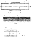
- connection tube 1 according to an embodiment of the present disclosure is shown in fig. 1 .
- the connection tube 1 has a central through-hole extending along a longitudinal axis A and has a first end portion 2 of a first alloy and a second end portion 3 of a second alloy. Between the end portions, a middle portion 4 which is double-layered extends. In the middle portion 4, the second alloy forms an annular inner layer 5 and the first alloy forms an annular outer layer 6. A metallic bond has been formed between the annular inner and outer layers 5, 6.
- the annular inner and outer layers 5, 6 are mechanically interlocked by means of at least one helically extending thread 7 formed in an interface between said layers 5, 6.
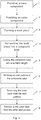
- the helically extending thread 7 is shown in fig. 2 , showing a cross sectional picture of a portion of a connection tube 1 according to an embodiment of the present disclosure.
- connection tube 1 has an inner diameter which is constant along the connection tube 1, i.e. at the first end portion 2, the middle portion 4 and the second end portion 3.
- the inner diameter may also vary along the connection tube, such that one of the end portions has a larger inner diameter than the other end portion.
- the connection tube 1 further has an outer diameter that is larger at the middle portion 4 than at the end portions 2, 3.
- a wall thickness of the connection tube 1 is therefore larger at the middle portion 4 than at the end portions 2, 3.
- the wall thickness at the middle portion 4 may be approximately double the wall thickness at the end portions 2, 3.
- a composite tube 101 as shown in fig. 3 is first manufactured, having an annular outer layer 102 and an annular inner layer 103 and extending along the longitudinal axis A.
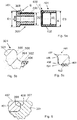
- a method for manufacturing a connection tube 1 is schematically illustrated in fig. 4 .
- a base component 301 of the second alloy which is to form the inner layer 5 of the connection tube 1 shown in fig. 1 .
- the base component 301 is a tube of circular cross section, having a central through-hole extending along the longitudinal axis A.
- An externally threaded section 302 is provided, having a helical thread 306 (see fig. 5b ) formed in an outer peripheral surface of the base component 301.
- the threaded section may extend over the entire base component or over a portion of the base component. In the embodiment shown in figs. 5a-c , it extends over an end portion of the base component 301, constituting a major part of the base component.
- the shown base component 301 also has a relatively short non-threaded section 303 adjacent the threaded section 302.
- An inner diameter d of the base component is constant or essentially constant along the longitudinal axis, but an outer diameter D1 of the non-threaded section 303 is larger than an outer diameter D2 of the threaded section 302.
- an outer component 401 of the first alloy is provided.
- the outer component 401 is also a tube of circular cross section, having a central through-hole extending along the longitudinal axis A.
- the outer component 401 has a length in the longitudinal direction corresponding to a length of the threaded section 302 of the base component 301.
- the outer component 401 has an internally threaded section 402, in the shown embodiment extending along the entire length of the outer component 401.
- a helical thread 406 (see fig. 5c ) is formed in an inner peripheral surface of the outer component 401.
- the outer component 401 is thereby configured for threaded engagement with the externally threaded section 302 of the base component 301.
- An outer diameter D3 of the outer component 401 is equal to or essentially equal to the outer diameter D1 of the non-threaded section 303 of the base component 301, while an inner diameter d2 of the outer component 401 matches the outer diameter D2 of the threaded section 302 of the base component 301.
- a tubular work piece is formed by mounting the outer component 401 around the base component 301 such that the internally threaded section 402 of the outer component 401 is in engagement with the externally threaded section 302 of the base component 301, i.e. by threading the outer component 401 onto the threaded end portion of the base component 301.
- a mechanical interlock is thereby formed between the threaded sections 302, 402.
- a fourth step 4 the work piece formed in the third step 3 is hot worked, e.g. by means of hot extrusion. During hot working, a metallic bond is formed between the threaded sections 302, 402 while the mechanical interlock is maintained. An outer diameter of the work piece is also reduced and a composite tube is formed. The composite tube may be straightened and/or pickled after hot working.
- the composite tube is cut into a suitable length, for example by cutting off the ends of the composite tube so that possible defects and undesired features are removed.
- a middle part of the composite tube corresponding to the composite tube 101 shown in fig. 3 , may thereafter be used in the following steps.
- the composite tube 101 has a dimension defined by an outer diameter ⁇ 1, an inner diameter ⁇ 2 and an interfacial diameter ⁇ 3.
- a first end portion 104 of the composite tube 101 which first end portion 104 is to form the first end portion 2 of the connection tube 1, is worked such that the inner and outer diameters ⁇ 1, ⁇ 2 of the composite tube 101 gradually decreases from a middle portion 105 of the composite tube toward the first end portion 104 such as shown schematically in fig. 7 .
- This can be achieved for example by compressing the first end portion 104 or by expanding the second end portion 106.
- a seventh step 7 the annular inner layer 103 is removed from the first end portion 104 thereby an increased inner diameter ⁇ 2 is obtained, for example by cutting machining.
- the annular outer layer 102 is removed from a second end portion 106 of the composite tube 101, for example by cutting machining, thus forming a connection tube 1 having a first end portion 2 of the first alloy and a second end portion 3 of the second alloy such as shown in fig. 1 .
- One or both of the end portions may, if desired, be provided with an internal or external thread adapted for threaded engagement with a threaded end of a tube.
- the end portions may be configured to be joined with other tubes by means of welding.
- the components 301, 401 shown in fig. 5a are adapted for hot extrusion by pushing the work piece through an extrusion die with a leading end first, wherein the leading end is the end at which the outer component 401 is mounted.
- a transition surface 308 between the externally threaded section 302 of the base component 301 and the non-threaded section 303 is smooth, without sharp edges.
- the transition surface 308 is shown in more detail in fig. 5b , showing a magnification of the encircled area B from fig. 5a .
- the transition surface is in cross section shaped as an inverted S with a concave portion 304 closest to the threaded section 302, and a convex portion 305 closest to the non-threaded section 303.
- the outer component 401 has an end surface 408 with a corresponding S-shape with a convex portion 404 close to the internal thread 406, and a concave portion 405 close to an outer peripheral surface 407 of the outer component 401 as shown in fig.5c , showing a magnification of the encircled area C from fig, 5a .
- the concave portion 405 of the end surface 408 will thereby overlap with the convex portion 305 of the transition surface 308, which prevents separation and penetration of oxygen during the extrusion process.
- the base component 301 is formed with a C-shaped concave transition surface 308, such that it floats over a rounded annular end surface 408 of the outer component 401 during extrusion and forms a seal.
- An outer peripheral surface 307 of the base component 301 thus overlaps the outer peripheral surface 407 of the outer component 401 when the components 301, 401 are mounted to form the work piece.
- a method for connecting two tubes 8, 9 of different alloys according to an embodiment of the present disclosure in order to form a tubular product 10 as shown in fig. 8 comprises providing a connection tube 1 as described above.
- the first alloy of the connection tube 1 is selected so that it is compatible with an alloy of a first one of the two tubes 8, 9 that are to be connected, and the second alloy of the connection tube 1 is selected so that it is compatible with an alloy of a second one of the two tubes 8, 9.
- the first tube 8 and the first end portion 2 of the connection tube 1 are joined together, e.g. by welding or by threaded engagement, depending on e.g. the weldability of the alloys used and the requirements on the joint.
- the second tube 9 and the second end portion 3 of the connection tube 1 are thereafter joined together, using a technique suitable with regard to e.g. the weldability of the alloys used and the requirements on the joint.
- the formed tubular product 10 comprises the first tube 8, the second tube 9 and the connection tube 1.
- connection tubes 1 as shown in fig. 1-2 were manufactured.
- the first alloy was in this case an austenitic stainless steel alloy according to ASTM 304L.
- the composition of the first alloy as measured in percent by weight (wt.%) is disclosed in Table I.
- Table I C Si Mn P S Cr Ni Fe ⁇ 0.030 0.5 1.3 ⁇ 0.030 ⁇ 0.015 18.5 10 balance
- the second alloy was a carbon steel according to ASTM Grade A-1 having a composition in wt.% as disclosed in Table II.
- Table II C Si Mn P S Fe 0.2 0.3 0.7 ⁇ 0.035 ⁇ 0.035 Balance
- Each base component had a total length of 520 mm, an outer diameter of 140 mm, and an inner diameter of 50 mm.
- An externally threaded section having a length of 130 mm was formed by cutting machining.
- the outer components each had a length of 130 mm and an inner diameter of 110 mm and were provided with an internal thread.
- the components had the transitional design shown in fig. 5a-c .
- the outer components were washed in an alkaline ultrasonic bath and the base components were degreased using ethanol. The outer components were thereafter threaded onto the base components to form work pieces.
- the work pieces were pre-heated at 400°C for four hours and were thereafter hot extruded with the end on which the outer component was mounted as the leading end.
- the work pieces were subsequently cooled, straightened and pickled to form composite tubes.
- a double-layered middle part of each resulting composite tube was cut out and heated.
- a second end portion 106 was expanded (upset) as shown in fig. 7 . Thereafter, the annular inner layer 103 was removed from the first end portion 104 and the annular outer layer 102 was removed from the second end portion 106 using cutting machining, thereby forming connection tubes.
Landscapes
- Engineering & Computer Science (AREA)
- Mechanical Engineering (AREA)
- General Engineering & Computer Science (AREA)
- Non-Disconnectible Joints And Screw-Threaded Joints (AREA)
- Pressure Welding/Diffusion-Bonding (AREA)
- Extrusion Of Metal (AREA)
- Mutual Connection Of Rods And Tubes (AREA)
- Rigid Pipes And Flexible Pipes (AREA)
Description
- The present disclosure relates to a connection tube for connecting two tubes according to the preamble of
claim 1. It further relates to a method for manufacturing such a connection tube according to the preamble ofclaim 5, a method for connecting two tubes of different alloys, and a tubular product comprising a connection tube. - For many industrial applications, there is a need to join tubes of different alloys and form a tubular product that is composed of several tube portions. This can be for example to save costs, since one part of a tube may be exposed to more demanding conditions than another part of the tube, which can therefore be made from a less expensive alloy. It may also be in order to tailor tubes that are likely to be subjected to demanding conditions varying along the tube, such as highly corrosive conditions along part of the tube and conditions requiring high mechanical strength along another part of the tube.
-
GB1258141 claim 1, discloses a method for joining two tubes of different alloys that are difficult to join by welding. According to this method, a connection tube is produced that has a first end portion of a first alloy, compatible with the alloy of one of the tubes, and a second end portion of a second alloy, compatible with the alloy of the other one of the tubes. Between the end portions, there is a middle portion in which the first alloy forms an outer layer and the second alloy forms an annular inner layer. A metallic bond has been formed between the layers by means of hot extrusion. The two tubes can thereafter be welded to the respective end portions of the connection tube. - Production of the connection tube disclosed in
GB1258141 - In view of the above-mentioned difficulties, it is desirable to provide means for joining two tubes of alloys that are difficult to join by welding, which is in at least some aspect improved with respect to previously known such means.
- According to a first aspect of the present disclosure, this is achieved by means of the connection as defined in
claim 8, wherein the annular inner layer and the annular outer layer are mechanically interlocked by means of at least one helically extending thread formed in an interface between said layers and in that said interface also has metallic bond which is formed between the threaded sections. By the term "connection tube" is meant a tube which will form a means for connecting two tubes of different materials. Thus, a connection tube is a tube which is used for connecting two tubes of different alloys and which also will allow welding between compatible alloys in the ends of the connection tube. By different alloys is meant that the composition of the alloys will be different, for example the ranges of alloying elements will differ or the composition may contain at least one different alloying element. - Further, the connecting tube according to the present disclosure may be efficiently produced in comparison with connection tubes manufactured according to previously known methods. The connection tube is also very stable due to the combination of the metallic bond and the mechanical interlock provided by the helically extending thread, which will increase the interfacial area between the annular inner and annular outer layers. Furthermore, the combination of a mechanical interlock in the form of a helically extending thread and a metallic bond between the layers is beneficial for the ability of the connection tube to withstand high forces. The helically extending thread forms an efficient interlock and also increases the interfacial area, which will thereby contribute to an improved distribution of forces applied to the connection tube in comparison with a connection tube without such a helically extending thread. Thus, the connection tube will be able to withstand higher forces in the interface between the layers.
- The metallic bond is formed by means of hot extrusion. The mechanical interlocking between the layers is provided before hot working. The mechanical interlock in the form of a helical thread will form a seal preventing oxygen from entering between the annular inner and annular outer layers during hot working, and it will also keep the components that are to form the annular inner and outer layers together during hot working. The mechanical interlock thereby makes it possible to achieve the proposed connection tube without having to use a vacuum pumped case enclosing a work piece which is to be extruded to form a composite tube from which the connection tube is formed. Thus, the connection tube can be formed without welding.
- The outer diameters of the connection tube may be different or equal at the first and the second end portions respectively, depending on the dimensions of the tubes which are to be connected by means of the connection tube and the desired properties of the connection tube.
- The proposed connection tube is configured for joining one tube to the first end portion of the connection tube and another tube to the second end portion of the connection tube. The tubes can be joined to the respective end portions by means of welding or by mechanical means, such as by threaded engagement. It is also possible to use a combination of those techniques.
- According to the invention, an inner diameter at the first end portion equals an inner diameter at the second end portion. The inner diameter may be constant or essentially constant along the longitudinal axis. The connection tube thereby has properties suitable for achieving a laminar flow of fluid through the connection tube. By "essentially constant" is herein intended a variation of less than ±10 % of an average inner diameter.
- According to the invention, the middle portion has a larger wall thickness than each of the end portions. For example, the outer diameter of the connection tube may be larger at the middle portion than at each of the end portions, while the inner diameter is the same along the connection tube. A larger interface between the annular inner and outer layers can thereby be achieved.
- According to one embodiment, at least one of the end portions is provided with an internal or external thread adapted for threaded engagement with a threaded end of a tube. The connection tube is thereby adapted for connection of alloys that are inherently difficult to join by welding. For example, such a threaded joint can be useful to join an iron chromium aluminium (FeCrAI) alloy tube to a first end portion made of the same alloy. If the second end portion of the connection tube is e.g. a carbon steel, a carbon steel tube can be joined to the second end portion by means of welding.
- According to another aspect, the disclosure relates to a method for manufacturing a connection tube for connecting two tubes of different alloys, as defined in
claim 1. - By mechanically interlocking the base component and the outer component by means of threaded engagement prior to hot working, a mechanical seal is formed. Additionally, the threading will create a large contact area between the surfaces of the annular base component and annular component, as the contact area will become greater thereby the area where the metallic bonds will be formed will also increase. Thus, the conditions for forming a metallic bond will be improved. It has furthermore been found that the mechanical seal provided by the threading is sufficient for preventing oxygen from entering between the annular base component and the annular outer component. The helical threading also efficiently prevents the components from both separating and sliding during hot working.
- The annular base and outer components may be configured so that, when the annular outer component has been threaded onto the annular base component, further axial movement of the outer component with respect to the base component is prevented. For this purpose, a stopping means can be provided at an end of the externally threaded section of the base component, preventing a leading end of the outer component during threading to be advanced further. Such a stopping means can for example be a section with a larger outer diameter than the outer diameter at the externally threaded section, or an externally projecting stopping member. An alternative is to provide a stopping means at a trailing end of the internally threaded section, preventing the trailing end from advancing further onto the base component in the axial direction. Such a stopping means can be in the form of a section with a smaller inner diameter than the inner diameter at the internally threaded section, or an internally projecting stopping member.
- According to the proposed method, a metallic bond is formed between the annular base and outer components during hot working while the mechanical interlock is maintained. The mechanical interlock, which can be seen as a helix formed in an interface between the annular inner and outer layers of the connection tube, increases the area of the interface and may thereby contribute to an improved distribution of forces applied to the connection tube in comparison with a connection tube without such a helix. Thus, connection tubes manufactured according to the proposed method may be able to withstand higher load in the interface.
- The metallic bond is formed by means of hot extrusion.
- According to one embodiment, the composite tube has a dimension defined by an outer diameter, an inner diameter and an interfacial diameter, and the step of working the first end portion of the composite tube is carried out such that the interfacial diameter of the first end portion corresponds to the inner diameter of the middle portion. This can for example be achieved by means of compression or tube drawing and facilitates formation of a connection tube having an inner diameter that is constant along the longitudinal axis.
- According to one embodiment, the method as defined herein optionally comprises a step of working the second end portion. This can be carried out such that the interfacial diameter of the second end portion corresponds to an outer diameter of the first portion. This can for example be achieved by means of expansion or upsetting and facilitates formation of a connection tube having an inner diameter that is constant along the longitudinal axis. Hence, both the first and second end portion may be worked and the working may be the same or different. According to one embodiment, the step of removing the annular inner layer comprises cutting machining and/or abrasive machining. According to one embodiment, the step of removing the annular outer layer comprises cutting machining and/or abrasive machining. Cutting machining and abrasive machining can efficiently remove desired portions of the annular inner and/or outer layer(s).
- According to one embodiment, the externally threaded section extends along an entire axial length of the annular base component. The annular base component is thereby well-suited for forming a double-layered composite tube with both layers extending along an entire axial length of the tube. As discussed above, a stopping means may be provided. According to one embodiment, the internally threaded section extends along an entire axial length of the annular outer component. If the threaded sections have equal lengths, the risk that oxygen enters between the components will be minimized and the conditions are well-suited for forming a metallic bond between the annular inner and outer layers of the composite tube.
- According to the invention, the step of hot working comprises hot extrusion. Hot extrusion is suitable for forming a metallic bond between the annular base component and the annular outer component while at the same time efficiently elongating and reducing the outer diameter of the work piece.
- According to one embodiment, the first alloy is selected from a stainless steel alloy, a nickel-based alloy, an iron chromium aluminium alloy, a carbon steel alloy, a zirconium alloy, an aluminium alloy, a copper alloy, or a titanium alloy.
- According to one embodiment, the second alloy has a different composition than the first alloy and is selected from a stainless steel alloy, a nickel-based alloy, an iron chromium aluminium alloy, a carbon steel alloy, a zirconium alloy, an aluminium alloy, a copper alloy, or a titanium alloy. The first and second alloys should be selected such as to match alloys of the tube that are to be connected by means of the connection tube.
- According to another aspect not falling under the scope of protection, the disclosure relates to a method for connecting two tubes of different alloys, comprising the steps of:
- providing the proposed connection tube, wherein the first alloy is compatible with an alloy of a first one of said two tubes, and wherein the second alloy is compatible with an alloy of a second one of said two tubes,
- joining the first tube and the first end portion of the connection tube together,
- joining the second tube and the second end portion of the connection tube together.
- According to one aspect not falling under the scope of protection, joining at least one of the first tube and the second tube with the connection tube comprises welding.
- According to another aspect not falling under the scope of protection, the disclosure relates to a tubular product comprising a first tube, a second tube and the proposed connection tube, wherein the first tube is joined with the first end portion of the connection tube, and wherein the second tube is joined with the second end portion of the connection tube.
- According to one aspect not falling under the scope of protection, a welded joint is formed between the connection tube and at least one of the first tube and the second tube. Other advantageous features as well as advantages of the disclosure will appear from the following description.
- Embodiments of the disclosure, not to be interpreted as limiting, will in the following be described with reference to the appended drawings, in which
- Fig. 1
- schematically shows a longitudinal cross section of a connection tube according to an embodiment,
- Fig. 2
- is a longitudinal cross sectional picture of a part of a connection tube according to an embodiment,
- Fig. 3
- schematically shows a composite tube manufactured using steps of the proposed method,
- Fig. 4
- is a flow chart illustrating an embodiment of the proposed method for manufacturing a connection tube,
- Fig. 5a-c
- schematically show a base component and an outer component used in an embodiment of the proposed method,
- Fig. 6
- schematically shows a longitudinal cross section of parts of a base component and an inner component used in an embodiment of the proposed method,
- Fig. 7
- schematically shows a longitudinal cross section of a composite tube manufactured using steps of the proposed method, and
- Fig. 8
- schematically shows a longitudinal cross section of a tubular product according to an embodiment.
- A
connection tube 1 according to an embodiment of the present disclosure is shown infig. 1 . Theconnection tube 1 has a central through-hole extending along a longitudinal axis A and has afirst end portion 2 of a first alloy and asecond end portion 3 of a second alloy. Between the end portions, amiddle portion 4 which is double-layered extends. In themiddle portion 4, the second alloy forms an annularinner layer 5 and the first alloy forms an annularouter layer 6. A metallic bond has been formed between the annular inner andouter layers outer layers thread 7 formed in an interface between saidlayers thread 7 is shown infig. 2 , showing a cross sectional picture of a portion of aconnection tube 1 according to an embodiment of the present disclosure. - The
connection tube 1 has an inner diameter which is constant along theconnection tube 1, i.e. at thefirst end portion 2, themiddle portion 4 and thesecond end portion 3. The inner diameter may also vary along the connection tube, such that one of the end portions has a larger inner diameter than the other end portion. Theconnection tube 1 further has an outer diameter that is larger at themiddle portion 4 than at theend portions connection tube 1 is therefore larger at themiddle portion 4 than at theend portions middle portion 4 may be approximately double the wall thickness at theend portions - In a method for manufacturing a
connection tube 1 according to an embodiment of the disclosure, acomposite tube 101 as shown infig. 3 is first manufactured, having an annularouter layer 102 and an annularinner layer 103 and extending along the longitudinal axis A. A method for manufacturing aconnection tube 1 is schematically illustrated infig. 4 . Reference is also made tofigs. 5a-c , showing abase component 301 and anouter component 401 used in the process, and tofigs. 6-8 . - In a
first step 1, abase component 301 of the second alloy, which is to form theinner layer 5 of theconnection tube 1 shown infig. 1 , is provided. Thebase component 301 is a tube of circular cross section, having a central through-hole extending along the longitudinal axis A. An externally threadedsection 302 is provided, having a helical thread 306 (seefig. 5b ) formed in an outer peripheral surface of thebase component 301. The threaded section may extend over the entire base component or over a portion of the base component. In the embodiment shown infigs. 5a-c , it extends over an end portion of thebase component 301, constituting a major part of the base component. The shownbase component 301 also has a relatively shortnon-threaded section 303 adjacent the threadedsection 302. An inner diameter d of the base component is constant or essentially constant along the longitudinal axis, but an outer diameter D1 of thenon-threaded section 303 is larger than an outer diameter D2 of the threadedsection 302. - In a
second step 2, anouter component 401 of the first alloy is provided. Theouter component 401 is also a tube of circular cross section, having a central through-hole extending along the longitudinal axis A. In the shown embodiment, theouter component 401 has a length in the longitudinal direction corresponding to a length of the threadedsection 302 of thebase component 301. Theouter component 401 has an internally threadedsection 402, in the shown embodiment extending along the entire length of theouter component 401. In other words, a helical thread 406 (seefig. 5c ) is formed in an inner peripheral surface of theouter component 401. Theouter component 401 is thereby configured for threaded engagement with the externally threadedsection 302 of thebase component 301. An outer diameter D3 of theouter component 401 is equal to or essentially equal to the outer diameter D1 of thenon-threaded section 303 of thebase component 301, while an inner diameter d2 of theouter component 401 matches the outer diameter D2 of the threadedsection 302 of thebase component 301. - In a
third step 3, a tubular work piece is formed by mounting theouter component 401 around thebase component 301 such that the internally threadedsection 402 of theouter component 401 is in engagement with the externally threadedsection 302 of thebase component 301, i.e. by threading theouter component 401 onto the threaded end portion of thebase component 301. A mechanical interlock is thereby formed between the threadedsections - In a
fourth step 4, the work piece formed in thethird step 3 is hot worked, e.g. by means of hot extrusion. During hot working, a metallic bond is formed between the threadedsections - In a
fifth step 5, the composite tube is cut into a suitable length, for example by cutting off the ends of the composite tube so that possible defects and undesired features are removed. A middle part of the composite tube, corresponding to thecomposite tube 101 shown infig. 3 , may thereafter be used in the following steps. Thecomposite tube 101 has a dimension defined by an outer diameter φ1, an inner diameter φ2 and an interfacial diameter φ3. - In a
sixth step 6, afirst end portion 104 of thecomposite tube 101, whichfirst end portion 104 is to form thefirst end portion 2 of theconnection tube 1, is worked such that the inner and outer diameters φ1, φ2 of thecomposite tube 101 gradually decreases from amiddle portion 105 of the composite tube toward thefirst end portion 104 such as shown schematically infig. 7 . This can be achieved for example by compressing thefirst end portion 104 or by expanding thesecond end portion 106. - In a
seventh step 7, the annularinner layer 103 is removed from thefirst end portion 104 thereby an increased inner diameter φ2 is obtained, for example by cutting machining. - In an
eighth step 8, the annularouter layer 102 is removed from asecond end portion 106 of thecomposite tube 101, for example by cutting machining, thus forming aconnection tube 1 having afirst end portion 2 of the first alloy and asecond end portion 3 of the second alloy such as shown infig. 1 . One or both of the end portions may, if desired, be provided with an internal or external thread adapted for threaded engagement with a threaded end of a tube. Alternatively, the end portions may be configured to be joined with other tubes by means of welding. - The
components fig. 5a are adapted for hot extrusion by pushing the work piece through an extrusion die with a leading end first, wherein the leading end is the end at which theouter component 401 is mounted. Atransition surface 308 between the externally threadedsection 302 of thebase component 301 and thenon-threaded section 303 is smooth, without sharp edges. Thetransition surface 308 is shown in more detail infig. 5b , showing a magnification of the encircled area B fromfig. 5a . The transition surface is in cross section shaped as an inverted S with aconcave portion 304 closest to the threadedsection 302, and aconvex portion 305 closest to thenon-threaded section 303. Theouter component 401 has anend surface 408 with a corresponding S-shape with aconvex portion 404 close to theinternal thread 406, and aconcave portion 405 close to an outerperipheral surface 407 of theouter component 401 as shown infig.5c , showing a magnification of the encircled area C fromfig, 5a . Theconcave portion 405 of theend surface 408 will thereby overlap with theconvex portion 305 of thetransition surface 308, which prevents separation and penetration of oxygen during the extrusion process. - Another option is to let the leading end in the extrusion process be the end on which no outer component is mounted. In this case, shown in
fig. 6 , thebase component 301 is formed with a C-shapedconcave transition surface 308, such that it floats over a roundedannular end surface 408 of theouter component 401 during extrusion and forms a seal. An outerperipheral surface 307 of thebase component 301 thus overlaps the outerperipheral surface 407 of theouter component 401 when thecomponents - A method for connecting two
tubes tubular product 10 as shown infig. 8 comprises providing aconnection tube 1 as described above. The first alloy of theconnection tube 1 is selected so that it is compatible with an alloy of a first one of the twotubes connection tube 1 is selected so that it is compatible with an alloy of a second one of the twotubes first tube 8 and thefirst end portion 2 of theconnection tube 1 are joined together, e.g. by welding or by threaded engagement, depending on e.g. the weldability of the alloys used and the requirements on the joint. Thesecond tube 9 and thesecond end portion 3 of theconnection tube 1 are thereafter joined together, using a technique suitable with regard to e.g. the weldability of the alloys used and the requirements on the joint. - The formed
tubular product 10 comprises thefirst tube 8, thesecond tube 9 and theconnection tube 1. - In a production trial, three
connection tubes 1 as shown infig. 1-2 were manufactured. Three outer components of a first alloy and three base components of a second alloy were formed. The first alloy was in this case an austenitic stainless steel alloy according to ASTM 304L. The composition of the first alloy as measured in percent by weight (wt.%) is disclosed in Table I.Table I C Si Mn P S Cr Ni Fe ≤0.030 0.5 1.3 ≤0.030 ≤0.015 18.5 10 balance - The second alloy was a carbon steel according to ASTM Grade A-1 having a composition in wt.% as disclosed in Table II.
Table II C Si Mn P S Fe 0.2 0.3 0.7 ≤0.035 ≤0.035 Balance - Each base component had a total length of 520 mm, an outer diameter of 140 mm, and an inner diameter of 50 mm. An externally threaded section having a length of 130 mm was formed by cutting machining. The outer components each had a length of 130 mm and an inner diameter of 110 mm and were provided with an internal thread. The components had the transitional design shown in
fig. 5a-c . - The outer components were washed in an alkaline ultrasonic bath and the base components were degreased using ethanol. The outer components were thereafter threaded onto the base components to form work pieces.
- The work pieces were pre-heated at 400°C for four hours and were thereafter hot extruded with the end on which the outer component was mounted as the leading end. The work pieces were subsequently cooled, straightened and pickled to form composite tubes. A double-layered middle part of each resulting composite tube was cut out and heated. A
second end portion 106 was expanded (upset) as shown infig. 7 . Thereafter, the annularinner layer 103 was removed from thefirst end portion 104 and the annularouter layer 102 was removed from thesecond end portion 106 using cutting machining, thereby forming connection tubes. - Material characterisation using optical microscopy of samples etched in nital and phosphoric acid showed that a metallic bond was formed between the components during hot extrusion. This was also confirmed using ultrasound. A helically extending
thread 7 was clearly visible in the interface between the inner andouter layers connection tubes 1 as shown infig. 2 . - The proposed methods and connection tube are not limited to the embodiments described above, but many possibilities to modifications thereof would be apparent to a person with skill in the art without departing from the scope of the appended claims.
Claims (9)
- A method for manufacturing a connection tube (1) for connecting two tubes (8, 9) of different alloys, said connection tube (1) having a first end portion (2) and a second end portion (3), the method comprising the steps of:- forming a composite tube (101) having an annular outer layer (102) of a first alloy and an annular inner layer (103) of a second alloy,- working a first end portion (104) of the composite tube (101) such that a diameter of the composite tube (101) gradually decreases from a middle portion (105) of the composite tube toward the first end portion (104),- removing the annular inner layer (103) from the first end portion (104) so that an inner diameter at the first end portion (2) equals an inner diameter at the second end portion (3), characterised by- removing the annular outer layer (102) from a second end portion (106) of the composite tube (101), so that a middle portion (4) extending between the first end portion (2) and the second end portion (3) has a larger wall thickness than each of the end portions (2, 3), thus forming a connection tube (1) having a first end portion (2) of said first alloy and a second end portion (3) of said second alloy, and in that the step of forming a composite tube (101) comprises the steps of:- providing an annular base component (301) of the second alloy, wherein the annular base component (301) has a central through-hole extending along a longitudinal axis (A) of the annular base component (301), and wherein the annular base component (301) has an externally threaded section (302),- providing an annular outer component (401) of the first alloy, wherein the annular outer component (401) has an internally threaded section (402) configured to engage with the externally threaded section (302) of the annular base component (301),- forming a tubular work piece by mounting the annular outer component (401) around the annular base component (301) such that the internally threaded section (402) of the outer component (401) is in engagement with the externally threaded section (302) of the annular base component (301), forming a mechanical interlock between the threaded sections (302, 402),- hot working the work piece, so that on one hand a metallic bond is formed between the threaded sections (302, 402) of the annular outer component (401) and the annular base component (301) while the mechanical interlock is maintained, and so that on the other hand the work piece is elongated and an outer diameter of the tubular work piece is reduced, thus forming a composite tube (101);
wherein the hot working step comprises extrusion. - The method according to claim 1, wherein the composite tube (101) has a dimension defined by an outer diameter (φ1), an inner diameter (φ2) and an interfacial diameter (φ3), and wherein the step of working the first end portion (104) of the composite tube (101) is carried out such that the interfacial diameter (φ3) of the first end portion (104) corresponds to the inner diameter (φ2) of the middle portion (105).
- The method according to claim 1 or 2, wherein at least one of the step of removing the annular inner layer (103) and the step of removing the annular outer layer (102) comprises cutting machining and/or abrasive machining.
- The method according to any one of claims 1-3, wherein the externally threaded section extends along an entire axial length of the annular base component.
- The method according to any one of claims 1-3, wherein the internally threaded section (402) extends along an entire axial length of the annular outer component (401).
- The method according to any one of claims 1-5, wherein the first alloy is selected from a stainless steel alloy, a nickel-based alloy, an iron chromium aluminium alloy, a carbon steel alloy, a zirconium alloy, an aluminium alloy, a copper alloy, or a titanium alloy.
- The method according to any one of claims 1-6, wherein the second alloy has a different composition than the first alloy and is selected from a stainless steel alloy, a nickel-based alloy, an iron chromium aluminium alloy, a carbon steel alloy, a zirconium alloy, an aluminium alloy, a copper alloy, or a titanium alloy.
- A connection tube (1) for connecting two tubes (8, 9) of different alloys manufactured according to claims 1-7, wherein the connection tube (1) has a central through-hole extending along a longitudinal axis (A) and comprises:- a first end portion (2) of a first alloy,- a second end portion (3) of a second alloy,- a middle portion (4) extending between the first end portion (2) and the second end portion (3), wherein the middle portion (4) is at least partly double-layered with said second alloy forming an annular inner layer (5) and said first alloy forming an annular outer layer (6), wherein a metallic bond has been formed between said layers (5, 6),wherein
that the annular inner layer (5) and the annular outer layer (6) are both mechanically interlocked by means of at least one helically extending thread (7) formed in an interface between said layers (5, 6) and that the interface having an extending thread also has metallic bond which is formed between the threaded sections and
wherein an inner diameter at the first end portion (2) equals an inner diameter at the second end portion (3); and wherein the middle portion (4) has a larger wall thickness than each of the end portions (2, 3). - A connection tube according to claim 8, wherein at least one of the end portions is provided with an internal or external thread adapted for threaded engagement with a threaded end of a tube.
Applications Claiming Priority (2)
| Application Number | Priority Date | Filing Date | Title |
|---|---|---|---|
| EP16206891 | 2016-12-23 | ||
| PCT/EP2017/084513 WO2018115501A1 (en) | 2016-12-23 | 2017-12-22 | A connection tube and its method of manufacturing |
Publications (2)
| Publication Number | Publication Date |
|---|---|
| EP3558554A1 EP3558554A1 (en) | 2019-10-30 |
| EP3558554B1 true EP3558554B1 (en) | 2021-02-17 |
Family
ID=57909421
Family Applications (1)
| Application Number | Title | Priority Date | Filing Date |
|---|---|---|---|
| EP17823160.1A Not-in-force EP3558554B1 (en) | 2016-12-23 | 2017-12-22 | A connection tube and its method of manufacturing |
Country Status (7)
| Country | Link |
|---|---|
| US (1) | US11679428B2 (en) |
| EP (1) | EP3558554B1 (en) |
| JP (1) | JP6942186B2 (en) |
| KR (1) | KR102386168B1 (en) |
| CN (1) | CN110099757B (en) |
| ES (1) | ES2857579T3 (en) |
| WO (1) | WO2018115501A1 (en) |
Families Citing this family (5)
| Publication number | Priority date | Publication date | Assignee | Title |
|---|---|---|---|---|
| JP7292314B2 (en) * | 2018-05-22 | 2023-06-16 | エービー サンドビック マテリアルズ テクノロジー | Tubular elements and tubular assemblies |
| CN111810058A (en) * | 2020-07-06 | 2020-10-23 | 中国石油天然气集团有限公司 | Coal underground gasification continuous pipe and connection method thereof |
| CN112742891B (en) * | 2020-12-16 | 2022-12-13 | 湖南华翔医疗科技有限公司 | Preparation method of medical degradable zinc-based composite pipe |
| CN116407738B (en) * | 2021-12-31 | 2026-02-17 | 上海博畅医疗科技有限公司 | A method for fabricating a multi-segment tube and a balloon catheter |
| CN115813494B (en) * | 2022-12-05 | 2026-02-27 | 深圳臣诺医疗器械有限公司 | Ultrasonic scalpel handle and surgical instruments |
Family Cites Families (13)
| Publication number | Priority date | Publication date | Assignee | Title |
|---|---|---|---|---|
| BE511483A (en) * | ||||
| DE906167C (en) * | 1951-10-09 | 1954-03-11 | Westdeutsche Mannesmannroehren | Welded connection for metallic workpieces, especially steel pipes |
| AT184039B (en) * | 1952-09-23 | 1955-12-10 | Schoeller Bleckmann Stahlwerke | Process for the production of pipe connections on drill rods for deep drilling |
| US3140108A (en) * | 1960-07-28 | 1964-07-07 | Joseph Lester Klein | Process and product of metallurgically joining zirconium to ferrous metal |
| US3208776A (en) * | 1960-09-06 | 1965-09-28 | Hydrocarbon Research Inc | Transition couplings |
| CH500778A (en) * | 1968-01-03 | 1970-12-31 | Cnen | Process for the production of pipes composed of several trunks in different metal |
| JPS5540311A (en) * | 1978-09-08 | 1980-03-21 | Tokyo Shibaura Electric Co | Jointing construction of pipes having differencial material quality |
| JPS6199590A (en) * | 1984-10-22 | 1986-05-17 | Kuroki Kogyosho:Kk | Pipe jointing of pipes of different kind metals and its production |
| US20060071473A1 (en) * | 2004-10-05 | 2006-04-06 | Sivley Robert S Iv | Helical groove for a tubular connection |
| DE202007009801U1 (en) * | 2007-07-13 | 2008-11-20 | Witzenmann Gmbh | Arrangement for fluid-tight connection of two pipe ends made of different metals |
| JP2013044423A (en) | 2011-08-26 | 2013-03-04 | Taku Seisakusho:Kk | Piping |
| CN104132207A (en) | 2014-08-09 | 2014-11-05 | 河北宏广橡塑金属制品有限公司 | Composite pipe joint and manufacturing method thereof |
| CN205424245U (en) * | 2016-01-13 | 2016-08-03 | 中国石油化工股份有限公司 | Joint connecting device |
-
2017
- 2017-12-22 US US16/472,238 patent/US11679428B2/en active Active
- 2017-12-22 WO PCT/EP2017/084513 patent/WO2018115501A1/en not_active Ceased
- 2017-12-22 ES ES17823160T patent/ES2857579T3/en active Active
- 2017-12-22 EP EP17823160.1A patent/EP3558554B1/en not_active Not-in-force
- 2017-12-22 KR KR1020197020352A patent/KR102386168B1/en not_active Expired - Fee Related
- 2017-12-22 CN CN201780079575.9A patent/CN110099757B/en not_active Expired - Fee Related
- 2017-12-22 JP JP2019532697A patent/JP6942186B2/en not_active Expired - Fee Related
Non-Patent Citations (1)
| Title |
|---|
| None * |
Also Published As
| Publication number | Publication date |
|---|---|
| CN110099757A (en) | 2019-08-06 |
| WO2018115501A1 (en) | 2018-06-28 |
| US11679428B2 (en) | 2023-06-20 |
| KR102386168B1 (en) | 2022-04-12 |
| ES2857579T3 (en) | 2021-09-29 |
| CN110099757B (en) | 2021-07-16 |
| JP2020509299A (en) | 2020-03-26 |
| JP6942186B2 (en) | 2021-09-29 |
| US20190314877A1 (en) | 2019-10-17 |
| EP3558554A1 (en) | 2019-10-30 |
| KR20190100935A (en) | 2019-08-29 |
Similar Documents
| Publication | Publication Date | Title |
|---|---|---|
| EP3558555B1 (en) | A method for manufacturing a composite tube | |
| US11679428B2 (en) | Connection tube and its method of manufacturing | |
| US7658419B2 (en) | Fitting and method for manufacturing a fitting | |
| JP6561394B2 (en) | Method for manufacturing multilayer pipes by expansion and multilayer pipes manufactured by said method | |
| KR102278376B1 (en) | Process for producing a multilayer pipe having a metallurgical bond by drawing, and multilayer pipe produced by this process | |
| US6007923A (en) | Titanium alloy, member made of the titanium alloy and method for producing the titanium alloy member | |
| EP1537921B1 (en) | Method of manufacturing a multi-layer tube for guiding heat transfer fluids and multi-layer tube | |
| US20190022801A1 (en) | Method of making a corrosion resistant tube | |
| US20080164695A1 (en) | Ferrules Manufactured From Hollow Stock | |
| US4515000A (en) | Method for manufacturing consumable welding spacer | |
| JPH04315524A (en) | Member for bonding together copper material and aluminum material and manufacture thereof | |
| KR20170132808A (en) | Aluminum alloy tube excellent in corrosion resistance and workability and manufacturing method thereof | |
| RU2403117C2 (en) | Method of producing bimetal small-diametre adaptor by multi-stage forming | |
| JP4975354B2 (en) | Manufacturing method of high strength welded steel pipe | |
| JP2008290104A (en) | Billet for clad tube and method for producing clad tube | |
| US20040031309A1 (en) | Method and a device for manufacturing of a closed profile and a profile manufactured according to said method | |
| RU2402397C1 (en) | Method of producing bimetal adapters | |
| JPS5939444A (en) | Production of steel flange | |
| JPS6362289B2 (en) | ||
| SU1278160A1 (en) | Laminated bar | |
| JPH0338928B2 (en) | ||
| JPS60106617A (en) | Billet for outer face clad extrusion and its manufacture | |
| JPH03275218A (en) | Manufacture of double layered reducer pipe fitting | |
| JPS623886A (en) | Electrode tip for spot welding |
Legal Events
| Date | Code | Title | Description |
|---|---|---|---|
| STAA | Information on the status of an ep patent application or granted ep patent |
Free format text: STATUS: UNKNOWN |
|
| STAA | Information on the status of an ep patent application or granted ep patent |
Free format text: STATUS: THE INTERNATIONAL PUBLICATION HAS BEEN MADE |
|
| PUAI | Public reference made under article 153(3) epc to a published international application that has entered the european phase |
Free format text: ORIGINAL CODE: 0009012 |
|
| STAA | Information on the status of an ep patent application or granted ep patent |
Free format text: STATUS: REQUEST FOR EXAMINATION WAS MADE |
|
| 17P | Request for examination filed |
Effective date: 20190723 |
|
| AK | Designated contracting states |
Kind code of ref document: A1 Designated state(s): AL AT BE BG CH CY CZ DE DK EE ES FI FR GB GR HR HU IE IS IT LI LT LU LV MC MK MT NL NO PL PT RO RS SE SI SK SM TR |
|
| AX | Request for extension of the european patent |
Extension state: BA ME |
|
| DAV | Request for validation of the european patent (deleted) | ||
| DAX | Request for extension of the european patent (deleted) | ||
| GRAP | Despatch of communication of intention to grant a patent |
Free format text: ORIGINAL CODE: EPIDOSNIGR1 |
|
| STAA | Information on the status of an ep patent application or granted ep patent |
Free format text: STATUS: GRANT OF PATENT IS INTENDED |
|
| INTG | Intention to grant announced |
Effective date: 20201103 |
|
| GRAS | Grant fee paid |
Free format text: ORIGINAL CODE: EPIDOSNIGR3 |
|
| GRAA | (expected) grant |
Free format text: ORIGINAL CODE: 0009210 |
|
| STAA | Information on the status of an ep patent application or granted ep patent |
Free format text: STATUS: THE PATENT HAS BEEN GRANTED |
|
| AK | Designated contracting states |
Kind code of ref document: B1 Designated state(s): AL AT BE BG CH CY CZ DE DK EE ES FI FR GB GR HR HU IE IS IT LI LT LU LV MC MK MT NL NO PL PT RO RS SE SI SK SM TR |
|
| REG | Reference to a national code |
Ref country code: GB Ref legal event code: FG4D |
|
| REG | Reference to a national code |
Ref country code: CH Ref legal event code: EP |
|
| REG | Reference to a national code |
Ref country code: DE Ref legal event code: R096 Ref document number: 602017032912 Country of ref document: DE |
|
| REG | Reference to a national code |
Ref country code: AT Ref legal event code: REF Ref document number: 1360803 Country of ref document: AT Kind code of ref document: T Effective date: 20210315 |
|
| REG | Reference to a national code |
Ref country code: IE Ref legal event code: FG4D |
|
| REG | Reference to a national code |
Ref country code: SE Ref legal event code: TRGR |
|
| REG | Reference to a national code |
Ref country code: LT Ref legal event code: MG9D |
|
| REG | Reference to a national code |
Ref country code: NL Ref legal event code: MP Effective date: 20210217 |
|
| PG25 | Lapsed in a contracting state [announced via postgrant information from national office to epo] |
Ref country code: LT Free format text: LAPSE BECAUSE OF FAILURE TO SUBMIT A TRANSLATION OF THE DESCRIPTION OR TO PAY THE FEE WITHIN THE PRESCRIBED TIME-LIMIT Effective date: 20210217 Ref country code: BG Free format text: LAPSE BECAUSE OF FAILURE TO SUBMIT A TRANSLATION OF THE DESCRIPTION OR TO PAY THE FEE WITHIN THE PRESCRIBED TIME-LIMIT Effective date: 20210517 Ref country code: PT Free format text: LAPSE BECAUSE OF FAILURE TO SUBMIT A TRANSLATION OF THE DESCRIPTION OR TO PAY THE FEE WITHIN THE PRESCRIBED TIME-LIMIT Effective date: 20210617 Ref country code: NO Free format text: LAPSE BECAUSE OF FAILURE TO SUBMIT A TRANSLATION OF THE DESCRIPTION OR TO PAY THE FEE WITHIN THE PRESCRIBED TIME-LIMIT Effective date: 20210517 Ref country code: GR Free format text: LAPSE BECAUSE OF FAILURE TO SUBMIT A TRANSLATION OF THE DESCRIPTION OR TO PAY THE FEE WITHIN THE PRESCRIBED TIME-LIMIT Effective date: 20210518 Ref country code: FI Free format text: LAPSE BECAUSE OF FAILURE TO SUBMIT A TRANSLATION OF THE DESCRIPTION OR TO PAY THE FEE WITHIN THE PRESCRIBED TIME-LIMIT Effective date: 20210217 Ref country code: HR Free format text: LAPSE BECAUSE OF FAILURE TO SUBMIT A TRANSLATION OF THE DESCRIPTION OR TO PAY THE FEE WITHIN THE PRESCRIBED TIME-LIMIT Effective date: 20210217 |
|
| REG | Reference to a national code |
Ref country code: AT Ref legal event code: MK05 Ref document number: 1360803 Country of ref document: AT Kind code of ref document: T Effective date: 20210217 |
|
| PG25 | Lapsed in a contracting state [announced via postgrant information from national office to epo] |
Ref country code: LV Free format text: LAPSE BECAUSE OF FAILURE TO SUBMIT A TRANSLATION OF THE DESCRIPTION OR TO PAY THE FEE WITHIN THE PRESCRIBED TIME-LIMIT Effective date: 20210217 Ref country code: PL Free format text: LAPSE BECAUSE OF FAILURE TO SUBMIT A TRANSLATION OF THE DESCRIPTION OR TO PAY THE FEE WITHIN THE PRESCRIBED TIME-LIMIT Effective date: 20210217 Ref country code: NL Free format text: LAPSE BECAUSE OF FAILURE TO SUBMIT A TRANSLATION OF THE DESCRIPTION OR TO PAY THE FEE WITHIN THE PRESCRIBED TIME-LIMIT Effective date: 20210217 Ref country code: RS Free format text: LAPSE BECAUSE OF FAILURE TO SUBMIT A TRANSLATION OF THE DESCRIPTION OR TO PAY THE FEE WITHIN THE PRESCRIBED TIME-LIMIT Effective date: 20210217 |
|
| REG | Reference to a national code |
Ref country code: ES Ref legal event code: FG2A Ref document number: 2857579 Country of ref document: ES Kind code of ref document: T3 Effective date: 20210929 |
|
| PG25 | Lapsed in a contracting state [announced via postgrant information from national office to epo] |
Ref country code: IS Free format text: LAPSE BECAUSE OF FAILURE TO SUBMIT A TRANSLATION OF THE DESCRIPTION OR TO PAY THE FEE WITHIN THE PRESCRIBED TIME-LIMIT Effective date: 20210617 |
|
| PG25 | Lapsed in a contracting state [announced via postgrant information from national office to epo] |
Ref country code: AT Free format text: LAPSE BECAUSE OF FAILURE TO SUBMIT A TRANSLATION OF THE DESCRIPTION OR TO PAY THE FEE WITHIN THE PRESCRIBED TIME-LIMIT Effective date: 20210217 Ref country code: SM Free format text: LAPSE BECAUSE OF FAILURE TO SUBMIT A TRANSLATION OF THE DESCRIPTION OR TO PAY THE FEE WITHIN THE PRESCRIBED TIME-LIMIT Effective date: 20210217 Ref country code: EE Free format text: LAPSE BECAUSE OF FAILURE TO SUBMIT A TRANSLATION OF THE DESCRIPTION OR TO PAY THE FEE WITHIN THE PRESCRIBED TIME-LIMIT Effective date: 20210217 |
|
| REG | Reference to a national code |
Ref country code: DE Ref legal event code: R097 Ref document number: 602017032912 Country of ref document: DE |
|
| PG25 | Lapsed in a contracting state [announced via postgrant information from national office to epo] |
Ref country code: RO Free format text: LAPSE BECAUSE OF FAILURE TO SUBMIT A TRANSLATION OF THE DESCRIPTION OR TO PAY THE FEE WITHIN THE PRESCRIBED TIME-LIMIT Effective date: 20210217 Ref country code: DK Free format text: LAPSE BECAUSE OF FAILURE TO SUBMIT A TRANSLATION OF THE DESCRIPTION OR TO PAY THE FEE WITHIN THE PRESCRIBED TIME-LIMIT Effective date: 20210217 Ref country code: SK Free format text: LAPSE BECAUSE OF FAILURE TO SUBMIT A TRANSLATION OF THE DESCRIPTION OR TO PAY THE FEE WITHIN THE PRESCRIBED TIME-LIMIT Effective date: 20210217 |
|
| PLBE | No opposition filed within time limit |
Free format text: ORIGINAL CODE: 0009261 |
|
| STAA | Information on the status of an ep patent application or granted ep patent |
Free format text: STATUS: NO OPPOSITION FILED WITHIN TIME LIMIT |
|
| 26N | No opposition filed |
Effective date: 20211118 |
|
| PG25 | Lapsed in a contracting state [announced via postgrant information from national office to epo] |
Ref country code: AL Free format text: LAPSE BECAUSE OF FAILURE TO SUBMIT A TRANSLATION OF THE DESCRIPTION OR TO PAY THE FEE WITHIN THE PRESCRIBED TIME-LIMIT Effective date: 20210217 |
|
| PG25 | Lapsed in a contracting state [announced via postgrant information from national office to epo] |
Ref country code: SI Free format text: LAPSE BECAUSE OF FAILURE TO SUBMIT A TRANSLATION OF THE DESCRIPTION OR TO PAY THE FEE WITHIN THE PRESCRIBED TIME-LIMIT Effective date: 20210217 |
|
| PG25 | Lapsed in a contracting state [announced via postgrant information from national office to epo] |
Ref country code: IS Free format text: LAPSE BECAUSE OF FAILURE TO SUBMIT A TRANSLATION OF THE DESCRIPTION OR TO PAY THE FEE WITHIN THE PRESCRIBED TIME-LIMIT Effective date: 20210617 |
|
| PG25 | Lapsed in a contracting state [announced via postgrant information from national office to epo] |
Ref country code: MC Free format text: LAPSE BECAUSE OF FAILURE TO SUBMIT A TRANSLATION OF THE DESCRIPTION OR TO PAY THE FEE WITHIN THE PRESCRIBED TIME-LIMIT Effective date: 20210217 |
|
| REG | Reference to a national code |
Ref country code: CH Ref legal event code: PL |
|
| REG | Reference to a national code |
Ref country code: BE Ref legal event code: MM Effective date: 20211231 |
|
| PG25 | Lapsed in a contracting state [announced via postgrant information from national office to epo] |
Ref country code: LU Free format text: LAPSE BECAUSE OF NON-PAYMENT OF DUE FEES Effective date: 20211222 Ref country code: IE Free format text: LAPSE BECAUSE OF NON-PAYMENT OF DUE FEES Effective date: 20211222 |
|
| PG25 | Lapsed in a contracting state [announced via postgrant information from national office to epo] |
Ref country code: BE Free format text: LAPSE BECAUSE OF NON-PAYMENT OF DUE FEES Effective date: 20211231 |
|
| PG25 | Lapsed in a contracting state [announced via postgrant information from national office to epo] |
Ref country code: LI Free format text: LAPSE BECAUSE OF NON-PAYMENT OF DUE FEES Effective date: 20211231 Ref country code: CH Free format text: LAPSE BECAUSE OF NON-PAYMENT OF DUE FEES Effective date: 20211231 |
|
| PG25 | Lapsed in a contracting state [announced via postgrant information from national office to epo] |
Ref country code: CY Free format text: LAPSE BECAUSE OF FAILURE TO SUBMIT A TRANSLATION OF THE DESCRIPTION OR TO PAY THE FEE WITHIN THE PRESCRIBED TIME-LIMIT Effective date: 20210217 |
|
| P01 | Opt-out of the competence of the unified patent court (upc) registered |
Effective date: 20230526 |
|
| PG25 | Lapsed in a contracting state [announced via postgrant information from national office to epo] |
Ref country code: HU Free format text: LAPSE BECAUSE OF FAILURE TO SUBMIT A TRANSLATION OF THE DESCRIPTION OR TO PAY THE FEE WITHIN THE PRESCRIBED TIME-LIMIT; INVALID AB INITIO Effective date: 20171222 |
|
| REG | Reference to a national code |
Ref country code: GB Ref legal event code: 732E Free format text: REGISTERED BETWEEN 20231026 AND 20231101 |
|
| PGFP | Annual fee paid to national office [announced via postgrant information from national office to epo] |
Ref country code: GB Payment date: 20231102 Year of fee payment: 7 |
|
| PGFP | Annual fee paid to national office [announced via postgrant information from national office to epo] |
Ref country code: SE Payment date: 20231110 Year of fee payment: 7 Ref country code: IT Payment date: 20231110 Year of fee payment: 7 Ref country code: DE Payment date: 20231031 Year of fee payment: 7 Ref country code: CZ Payment date: 20231128 Year of fee payment: 7 Ref country code: FR Payment date: 20231122 Year of fee payment: 7 |
|
| REG | Reference to a national code |
Ref country code: DE Ref legal event code: R081 Ref document number: 602017032912 Country of ref document: DE Owner name: ALLEIMA TUBE AB, SE Free format text: FORMER OWNER: SANDVIK INTELLECTUAL PROPERTY AB, SANDVIKEN, SE |
|
| PGFP | Annual fee paid to national office [announced via postgrant information from national office to epo] |
Ref country code: ES Payment date: 20240111 Year of fee payment: 7 |
|
| PG25 | Lapsed in a contracting state [announced via postgrant information from national office to epo] |
Ref country code: MK Free format text: LAPSE BECAUSE OF FAILURE TO SUBMIT A TRANSLATION OF THE DESCRIPTION OR TO PAY THE FEE WITHIN THE PRESCRIBED TIME-LIMIT Effective date: 20210217 |
|
| PG25 | Lapsed in a contracting state [announced via postgrant information from national office to epo] |
Ref country code: MT Free format text: LAPSE BECAUSE OF FAILURE TO SUBMIT A TRANSLATION OF THE DESCRIPTION OR TO PAY THE FEE WITHIN THE PRESCRIBED TIME-LIMIT Effective date: 20210217 |
|
| REG | Reference to a national code |
Ref country code: ES Ref legal event code: PC2A Owner name: ALLEIMA TUBE AB Effective date: 20240927 |
|
| REG | Reference to a national code |
Ref country code: DE Ref legal event code: R119 Ref document number: 602017032912 Country of ref document: DE |
|
| PG25 | Lapsed in a contracting state [announced via postgrant information from national office to epo] |
Ref country code: CZ Free format text: LAPSE BECAUSE OF NON-PAYMENT OF DUE FEES Effective date: 20241222 |
|
| REG | Reference to a national code |
Ref country code: SE Ref legal event code: EUG |
|
| GBPC | Gb: european patent ceased through non-payment of renewal fee |
Effective date: 20241222 |
|
| PG25 | Lapsed in a contracting state [announced via postgrant information from national office to epo] |
Ref country code: DE Free format text: LAPSE BECAUSE OF NON-PAYMENT OF DUE FEES Effective date: 20250701 |
|
| PG25 | Lapsed in a contracting state [announced via postgrant information from national office to epo] |
Ref country code: IT Free format text: LAPSE BECAUSE OF NON-PAYMENT OF DUE FEES Effective date: 20241222 |
|
| PG25 | Lapsed in a contracting state [announced via postgrant information from national office to epo] |
Ref country code: GB Free format text: LAPSE BECAUSE OF NON-PAYMENT OF DUE FEES Effective date: 20241222 |
|
| PG25 | Lapsed in a contracting state [announced via postgrant information from national office to epo] |
Ref country code: FR Free format text: LAPSE BECAUSE OF NON-PAYMENT OF DUE FEES Effective date: 20241231 |
|
| PG25 | Lapsed in a contracting state [announced via postgrant information from national office to epo] |
Ref country code: TR Free format text: LAPSE BECAUSE OF FAILURE TO SUBMIT A TRANSLATION OF THE DESCRIPTION OR TO PAY THE FEE WITHIN THE PRESCRIBED TIME-LIMIT Effective date: 20210217 |
|
| REG | Reference to a national code |
Ref country code: ES Ref legal event code: FD2A Effective date: 20260204 |
|
| PG25 | Lapsed in a contracting state [announced via postgrant information from national office to epo] |
Ref country code: ES Free format text: LAPSE BECAUSE OF NON-PAYMENT OF DUE FEES Effective date: 20241223 |