EP3558545B1 - Intuitive width control sprinkler - Google Patents
Intuitive width control sprinkler Download PDFInfo
- Publication number
- EP3558545B1 EP3558545B1 EP17823294.8A EP17823294A EP3558545B1 EP 3558545 B1 EP3558545 B1 EP 3558545B1 EP 17823294 A EP17823294 A EP 17823294A EP 3558545 B1 EP3558545 B1 EP 3558545B1
- Authority
- EP
- European Patent Office
- Prior art keywords
- jets
- jet
- toggle
- slider
- sprinkler
- Prior art date
- Legal status (The legal status is an assumption and is not a legal conclusion. Google has not performed a legal analysis and makes no representation as to the accuracy of the status listed.)
- Active
Links
- 238000003079 width control Methods 0.000 title description 9
- 239000012530 fluid Substances 0.000 claims description 78
- 230000007246 mechanism Effects 0.000 description 21
- 238000010168 coupling process Methods 0.000 description 15
- 230000008878 coupling Effects 0.000 description 14
- 238000005859 coupling reaction Methods 0.000 description 14
- 230000002262 irrigation Effects 0.000 description 12
- 238000003973 irrigation Methods 0.000 description 12
- 230000008859 change Effects 0.000 description 9
- 238000010276 construction Methods 0.000 description 9
- XLYOFNOQVPJJNP-UHFFFAOYSA-N water Substances O XLYOFNOQVPJJNP-UHFFFAOYSA-N 0.000 description 9
- 238000005452 bending Methods 0.000 description 8
- 239000000463 material Substances 0.000 description 7
- 230000008901 benefit Effects 0.000 description 5
- 239000003086 colorant Substances 0.000 description 5
- 239000000853 adhesive Substances 0.000 description 4
- 230000001070 adhesive effect Effects 0.000 description 4
- 229920002725 thermoplastic elastomer Polymers 0.000 description 4
- 239000004033 plastic Substances 0.000 description 3
- 229920003023 plastic Polymers 0.000 description 3
- 230000003466 anti-cipated effect Effects 0.000 description 2
- 230000009286 beneficial effect Effects 0.000 description 2
- 230000007423 decrease Effects 0.000 description 2
- 230000003247 decreasing effect Effects 0.000 description 2
- 238000000926 separation method Methods 0.000 description 2
- 239000007921 spray Substances 0.000 description 2
- 230000000007 visual effect Effects 0.000 description 2
- 238000003462 Bender reaction Methods 0.000 description 1
- 229910001369 Brass Inorganic materials 0.000 description 1
- 229910000831 Steel Inorganic materials 0.000 description 1
- 239000000956 alloy Substances 0.000 description 1
- 229910052782 aluminium Inorganic materials 0.000 description 1
- XAGFODPZIPBFFR-UHFFFAOYSA-N aluminium Chemical compound [Al] XAGFODPZIPBFFR-UHFFFAOYSA-N 0.000 description 1
- 239000010951 brass Substances 0.000 description 1
- 238000004891 communication Methods 0.000 description 1
- 230000000295 complement effect Effects 0.000 description 1
- 239000002131 composite material Substances 0.000 description 1
- 229920001971 elastomer Polymers 0.000 description 1
- 239000003337 fertilizer Substances 0.000 description 1
- 239000003292 glue Substances 0.000 description 1
- 230000003116 impacting effect Effects 0.000 description 1
- 238000003780 insertion Methods 0.000 description 1
- 230000037431 insertion Effects 0.000 description 1
- 229910052751 metal Inorganic materials 0.000 description 1
- 239000002184 metal Substances 0.000 description 1
- 229910001092 metal group alloy Inorganic materials 0.000 description 1
- 239000000203 mixture Substances 0.000 description 1
- 238000012986 modification Methods 0.000 description 1
- 230000004048 modification Effects 0.000 description 1
- 230000010355 oscillation Effects 0.000 description 1
- 238000012552 review Methods 0.000 description 1
- 239000010959 steel Substances 0.000 description 1
Images


Classifications
-
- B—PERFORMING OPERATIONS; TRANSPORTING
- B05—SPRAYING OR ATOMISING IN GENERAL; APPLYING FLUENT MATERIALS TO SURFACES, IN GENERAL
- B05B—SPRAYING APPARATUS; ATOMISING APPARATUS; NOZZLES
- B05B3/00—Spraying or sprinkling apparatus with moving outlet elements or moving deflecting elements
- B05B3/02—Spraying or sprinkling apparatus with moving outlet elements or moving deflecting elements with rotating elements
- B05B3/04—Spraying or sprinkling apparatus with moving outlet elements or moving deflecting elements with rotating elements driven by the liquid or other fluent material discharged, e.g. the liquid actuating a motor before passing to the outlet
- B05B3/0409—Spraying or sprinkling apparatus with moving outlet elements or moving deflecting elements with rotating elements driven by the liquid or other fluent material discharged, e.g. the liquid actuating a motor before passing to the outlet with moving, e.g. rotating, outlet elements
- B05B3/0418—Spraying or sprinkling apparatus with moving outlet elements or moving deflecting elements with rotating elements driven by the liquid or other fluent material discharged, e.g. the liquid actuating a motor before passing to the outlet with moving, e.g. rotating, outlet elements comprising a liquid driven rotor, e.g. a turbine
- B05B3/0422—Spraying or sprinkling apparatus with moving outlet elements or moving deflecting elements with rotating elements driven by the liquid or other fluent material discharged, e.g. the liquid actuating a motor before passing to the outlet with moving, e.g. rotating, outlet elements comprising a liquid driven rotor, e.g. a turbine with rotating outlet elements
- B05B3/0431—Spraying or sprinkling apparatus with moving outlet elements or moving deflecting elements with rotating elements driven by the liquid or other fluent material discharged, e.g. the liquid actuating a motor before passing to the outlet with moving, e.g. rotating, outlet elements comprising a liquid driven rotor, e.g. a turbine with rotating outlet elements the rotative movement of the outlet elements being reversible
- B05B3/044—Tubular elements holding several outlets, e.g. apertured tubes, oscillating about an axis substantially parallel to the tubular element
-
- B—PERFORMING OPERATIONS; TRANSPORTING
- B05—SPRAYING OR ATOMISING IN GENERAL; APPLYING FLUENT MATERIALS TO SURFACES, IN GENERAL
- B05B—SPRAYING APPARATUS; ATOMISING APPARATUS; NOZZLES
- B05B15/00—Details of spraying plant or spraying apparatus not otherwise provided for; Accessories
- B05B15/60—Arrangements for mounting, supporting or holding spraying apparatus
- B05B15/65—Mounting arrangements for fluid connection of the spraying apparatus or its outlets to flow conduits
- B05B15/652—Mounting arrangements for fluid connection of the spraying apparatus or its outlets to flow conduits whereby the jet can be oriented
-
- A—HUMAN NECESSITIES
- A01—AGRICULTURE; FORESTRY; ANIMAL HUSBANDRY; HUNTING; TRAPPING; FISHING
- A01G—HORTICULTURE; CULTIVATION OF VEGETABLES, FLOWERS, RICE, FRUIT, VINES, HOPS OR SEAWEED; FORESTRY; WATERING
- A01G25/00—Watering gardens, fields, sports grounds or the like
- A01G25/02—Watering arrangements located above the soil which make use of perforated pipe-lines or pipe-lines with dispensing fittings, e.g. for drip irrigation
-
- B—PERFORMING OPERATIONS; TRANSPORTING
- B05—SPRAYING OR ATOMISING IN GENERAL; APPLYING FLUENT MATERIALS TO SURFACES, IN GENERAL
- B05B—SPRAYING APPARATUS; ATOMISING APPARATUS; NOZZLES
- B05B3/00—Spraying or sprinkling apparatus with moving outlet elements or moving deflecting elements
- B05B3/02—Spraying or sprinkling apparatus with moving outlet elements or moving deflecting elements with rotating elements
- B05B3/021—Spraying or sprinkling apparatus with moving outlet elements or moving deflecting elements with rotating elements with means for regulating the jet relative to the horizontal angular position of the nozzle, e.g. for spraying non circular areas by changing the elevation of the nozzle or by varying the nozzle flow-rate
Definitions
- the present disclosure relates to irrigation devices. More particularly, the present disclosure relates to a width control mechanism for a sprinkler.
- Irrigation devices such as sprinklers
- fluid such as water
- desired areas typically without user control.
- owners/users of the irrigation devices to tend to other tasks while fluid is being provided to a desired area (e.g., a region of a lawn, a flower bed, etc.).
- irrigation devices including, but not limited to: a pop-up sprinkler that is stored at or below a ground surface that selectively "pops-up" when in use to provide fluid; impact or impulse sprinklers that utilize fluid flow to drive rotation of the spray nozzle of the sprinkler; fixed spray sprinklers that provide a fixed stream of fluid (e.g., no rotation or other movement); oscillating sprinklers that provide a stream of fluid and oscillate about an axis of rotation; and various other types of irrigation devices.
- a previously known irrigation device is disclosed in US 6 135 356 A .
- Oscillating sprinklers are a popular choice for residential (e.g., home lawns) and commercial (e.g., golf courses) uses.
- the oscillating sprinkler is inserted or rested upon a ground surface, coupled to a fluid source, and activated to provide a stream of fluid in an oscillating manner about an axis of rotation.
- the oscillating sprinkler typically includes a plurality of jets or nozzles arranged axially or substantially axially along a body of the oscillating sprinkler. As such, as the body rotates about the axis, the jets also rotate about the axis.
- a "width" control knob is typically included with the oscillating sprinkler.
- the width control knob enables a user to adjust an angle of emission of the fluid from the plurality of jets: a large angle corresponds with a greater coverage area than a small angle. While such a knob is beneficial in tailoring the emitted fluid to the intended area, the placement of the width control knob is typically in an inconvenient/cumbersome location for the user especially when the sprinkler is in use.
- the present invention relates to a sprinkler according to independent claim 1.
- the sprinkler includes a body defining a fluid passage; a frame coupled to the body, the frame disposed in an internal volume of the body proximate the fluid passage, wherein the frame defines a plurality of apertures; a first toggle movably coupled to the body; a first slider disposed within the internal volume of the body and coupled to the first toggle, the first slider defining a plurality of apertures; and, a first plurality of jets coupled to the frame, wherein each jet in the first plurality of jets is received by an aperture of each of the first slider and the frame, and wherein fluid from the fluid passage is selectively provided to the first plurality of jets.
- the first toggle is movable between a first position and a second position, wherein movement of the first toggle to the second position moves the first slider in a same direction as the first toggle, wherein the movement of the first slider in the same direction causes the first slider to move at least one jet in the first plurality of jets in the same direction such that the at least one jet moves in the same direction as the first toggle.
- an irrigation device with an intuitive width control mechanism is shown herein.
- the irrigation device is configured as an oscillating sprinkler that includes the intuitive width control mechanism.
- the oscillating sprinkler includes a body, a first plurality of jets, a second plurality of jets, a first slider cooperating with the first plurality of jets, a second slider cooperating with the second plurality of jets, a first toggle coupled to the first slider, and among other components a second toggle coupled to the second slider.
- the body is rotatable about a longitudinal axis to provide the oscillation feature of the oscillating sprinkler.
- the first and second pluralities of jets are resiliently flexibly and configured to emit a fluid (e.g., water) when the sprinkler is in use.
- the first and second toggles are coupled to the body and, according to the present disclosure, are rotatable about an axis that is perpendicular or substantially perpendicular to the axis of rotation of the body.
- the first and second toggles are positioned along or substantially along the axis of rotation of the body.
- rotation of the first and second toggles moves the first and second sliders, respectively. Movement of the first and second sliders impacts at least one of the jets in the first and second pluralities of jets, respectively, to push the at least one of the jets in the first and second pluralities of jets.
- the at least one jet in the first and second pluralities of jets is angularly bent.
- the angular movement of the at least one jet in the first and second pluralities of jets respectively, adjusts a width of dispersal of the emitted fluid (hence, a "width" control mechanism) from the sprinkler.
- the width control mechanism may enable a user to control the coverage area of the emitted fluid from the oscillating sprinkler to correspond with or substantially correspond with a desired coverage area (i.e., an area desired to be wetted).
- the first toggle cooperates with the first plurality of jets while the second toggle cooperates with the second plurality of jets such that each plurality of jets is independently adjustable.
- a user may rotate the first toggle to provide a wide or large jet angle for the first plurality of jets while adjusting the second toggle provide a narrow or small jet angle for the second plurality of jets.
- such tailoring may enable the user to better control the coverage area as compared to conventional oscillating sprinklers.
- the angle of rotation of the toggle substantially corresponds with the angle of at least one of the jets. As such, a user can observe the anticipated fluid dispersal angle without having to turn the fluid on/off to gain an indication. Therefore, a time-savings and convenience benefit may be realized.
- the type of fluid may be highly configurable.
- the type of fluid may be water, which may be provided by a spigot or other water source.
- a reservoir containing a mixture of water and fertilizer may be used by the sprinkler.
- a variety of other types of fluids may be used.
- the irrigation device of the present disclosure may provide water in addition to various other types of fluids.
- an irrigation device shown as an oscillating sprinkler 100
- the oscillating sprinkler 100 is configured to emit fluid to wet or substantially wet a desired area.
- the oscillating sprinkler 100 includes a base 101 coupled to a body 110, an end cap 111, a fluid inlet 112, a pair of toggles shown as a first toggle 180a and a second toggle 180b, a plurality of jets 141 coupled to the body 110 and split into a first plurality of jets 143 and a second plurality of jets 144, and various other components described herein below.
- the body 110 rotates about an axis 200 (hence, an "oscillating" sprinkler).
- the plurality of jets 141 is substantially aligned with the axis 200.
- the axis 200 corresponds with an alignment axis for the plurality of jets 141 and the toggles 180a, 180b, where the plurality of jets 141 and toggles 180a, 180b are aligned with that axis in a straight or substantially straight line.
- the jets 141 and toggles 180a, 180b may be disposed differently than shown and described (e.g., a random pattern, not aligned in a substantially straight line, etc.).
- this straight line arrangement between the toggles 180a, 180b and the jets 141 may aid a user in visualizing the movement of the jets 141 as one or more of the toggles 180a and 180b are rotated, moved, or otherwise actuated.
- Fluid provided via the fluid inlet 112 to the plurality of jets 141 is emitted about the axis 200 as the body 110 rotates about the axis 200.
- any type of drive mechanism to cause rotation of the body 110 (or a portion thereof) about the axis 200 may be used with sprinkler 100.
- a motor such as an electric motor may be used.
- a fluid-driven rotation mechanism shown as a turbine or water wheel 113, may be utilized to drive the body 110 about the axis 200. As fluid impacts the water wheel 113, the water wheel 113 is driven to, in turn, cause rotation of the body 110.
- this drive mechanism may be one or more speed control mechanisms (e.g., gear trains) to control the rotational speed of the body 110 about the axis 200 independent of the fluid pressure provided to the sprinkler 100 via the fluid inlet 112.
- the base 101 may be structured to support the body 110 above a support surface (e.g., ground surface).
- a support surface e.g., ground surface
- the base 101 is shown to be configured as a rest-type base where the base 101 rests upon a support surface.
- the base 101 may be configured as an insertable-type base (e.g., spike) that facilitates and enables insertion of the base 101 into the support surface. This configuration may be desired to substantially securely hold the base 101 (and, in turn, the oscillating sprinkler 100) in a desired location. It should be understood that many coupling devices or mechanisms may be used to couple the body 110 to the base 101.
- the body 110 may simply rest in an opening or snap into an opening of the base 101 to suspend the body 110 above or substantially above the support surface.
- the base 101 may be of integral construction with, for example, the fluid inlet 112 and the end cap 111.
- the body 110 or housing is shown as a substantially hollow tube structured to support and couple to many of the components described herein.
- the body 110 has a cylindrical shape where the axis 200 is aligned or substantially aligned with the longitudinal axis of the body 110.
- the body 110 defines a circular or substantially circular cross-section.
- the plurality of jets 141 is provided on a curved surface of the body 110. Additional features of the body 110 are described herein below with respect to FIG. 3 .
- the fluid inlet 112 is structured to permit and enable coupling of the sprinkler 100 to a fluid source (e.g., a hose connected to a spigot or other fluid source). As such, the fluid inlet 112 defines a fluid entry point for the sprinkler 100. In one embodiment (see FIGS. 3-4 ), the fluid inlet 112 may define/include a plurality of threads that are rotatably engageable with a complementary plurality of threads on the fluid source. In another embodiment, any type of fluid connection/coupling mechanism or device may be used (e.g., a quick-connect feature, a snap engagement, etc.).
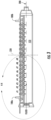
- FIG. 2 depicts an exploded assembly view of the sprinkler 100 with the base 101 removed
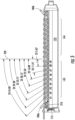
- FIG. 3 depicts a side cross-sectional view of the sprinkler 100 with the base 101 removed and the plurality of jets 141 in a narrow or starting position
- FIG. 4 depicts a close-up view of section 4-4 from FIG. 3
- FIG. 5 depicts a side cross-sectional view of the sprinkler 100 with the base 101 removed and the plurality of jets 141 in an end or wide position.
- the jets 141 may be described herein to be movable from a starting (or narrow) position to an end (or wide) position.
- the terms “narrow” and “wide” refer to the fluid dispersal coverage area.
- the jets 141 In the wide position, the jets 141 (or at least some of the plurality of jets) are angled outward and away from the body 110.
- the jets 141 In the narrow position, the jets 141 (or at least some of the plurality of jets) are positioned in a substantially upright position (i.e., parallel to the vertical plane 220).
- the wetted area from the sprinkler 100 is wider in the wide position than in the narrow position.
- the oscillating sprinkler 100 includes a lower or bottom part 120 of the body 110, an upper or top part 130 of the body 110, a plurality of jets 141 (also referred to herein as nozzles), a pair of nozzle or jet bend controllers 150a and 150b, a pair of bottom sliders 160a and 160b, a pair of top sliders 170a and 170b, and a pair of toggles 180a and 180b.
- nozzles also referred to herein as nozzles
- each component in the pair of nozzle bend controllers 150a and 150b, bottom sliders 160a and 160b, top sliders 170a and 170b, and toggles 180a and 180b are identical in structure to each other.
- the body 110 includes a bottom part 120 (e.g., section, housing, portion, etc.) and a top part 130.
- the body 110 may be constructed (at least partly) from by two parts.
- the bottom part 120 includes a frame 121 that defines a plurality of apertures 122 (e.g., openings, holes, etc.) and a fluid passage 123 (e.g., channel, etc.) defined by the body 110.
- the fluid passage 123 is fluidly coupled to the fluid inlet 112, such that fluid may be provided from the inlet 112 to the passage 123 and, eventually, the jets 141.
- the fluid passage 123 is coaxial or substantially coaxial with the axis 200.
- the fluid passage 123 may have any shape and size desired by the designer. In the example shown, the fluid passage 123 corresponds with a circular or substantially circular cross-sectional shape. Of course, in other embodiments, any shape and size may be used.
- the frame 121 (e.g., rail, etc.) is disposed on a top or upper part of the fluid passage 123 (based on the viewpoint in FIG. 3 ).
- the frame 121 is a predominately flat component of unitary construction.
- the frame 121 defines a plurality of apertures 122.
- the apertures 122 are in fluid communication with the fluid passage 123. In this regard, fluid in the passage 123 may escape via the apertures 122.
- the apertures 122 are disposed in a straight or substantially straight line along the axis 200. In other configurations, the apertures 122 may be offset relative to each other or arranged in a different, desired pattern.
- the apertures 122 correspond with a shape of the jets (e.g., circular shaped). Of course, in other embodiments, a variety of shapes may be used (e.g., slot or oval shaped, rectangular, square, etc.). As described herein below, the frame 121 and apertures 122 couple to the plurality of jets 140 when the sprinkler 100 is assembled.
- the upper part 130 couples to the bottom part 120 to form the body 110.
- the upper part 130 includes a pair of openings 131 (e.g., apertures, voids, etc.) structured to receives the toggles 180a and 180b (one toggle per opening 131) and a plurality of apertures 132 (e.g., holes) arranged longitudinally across a top or upper surface of the upper part 130, such that the openings 132 are aligned or substantially aligned with the axis 200.
- a pair of openings 131 e.g., apertures, voids, etc.
- apertures 132 e.g., holes
- Coupling of the upper part 130 to the lower part 120 may be via any type of coupling mechanism including, but not limited to, a snap engagement, one or more fasteners (e.g., screws, pins, etc.), an adhesive (e.g., glue), an interference type relationship, etc.
- the openings 132 have a slot or oval type shape, where the length of the slot (i.e., the long portion) is oriented along the axis 200.
- each jet 141 is configured to extend through each opening 132 (i.e., one jet per opening).
- the slotshape is beneficial due to the structure of the opening 132 itself then not impacting or restricting the movement capability of the jets 140.
- the jets 140 may move and, particularly, angularly move with respect to the openings 132. This operation is described more fully herein below.
- the jet rail 140 includes a plurality of jets 141 (also referred to herein as nozzles) extending upward and away from a body 142.
- the jet rail 140 is divided up into a first plurality of jets 143 and a second plurality of jets 144. This is done to signify which of the pluralities of jets 141 are controllable by which toggle 180a or 180b.
- the first plurality of jets 143 may be controllable or movable by the toggle 180a on the left-hand side (close to the fluid inlet 112) while the second plurality of jets 144 may be controllable or movable by the toggle 180b on the right-hand side (close to the end cap 111).
- the jet rail 140 is insertable underneath the frame 121.
- each jet 141 in the plurality of jets 141 extends up and through the apertures 122.
- Coupling of the jet rail 140 to the frame 121 may be performed in any of a variety of manners.
- an adhesive is applied to at least one of the frame 121 and the jet rail 140 to bond the two components together.
- the frame 121 defines or includes features that enable the coupling (e.g., a snap-engagement, etc.).
- one or more fasteners may be used.
- coupling between the frame 121 and the jet rail 140 may be performed in a fluid tight manner or substantially a fluid tight manner.
- fluid provided to the passage 123 can only be directed through each of the pluralities of jets 141 as opposed to a space or crevice between the jet rail 140 and the frame 121. Beneficially, such a feature avoids leaks there-between.
- the jets 141 and body 142 are of integral construction (e.g., a one-piece component).
- the jet rail 140 is constructed from a material that is capable of bending and flexion.
- the jet rail 140 is constructed from thermoplastic elastomers (TPE) or thermoplastic rubber (TPR).
- TPE thermoplastic elastomers
- TPR thermoplastic rubber
- the jets 141 have a resilient bending characteristic (i.e., able to bent and spring or revert back to a default shape or position).
- the bending capability of the jets 141 enables them to be controllably bent/moved into one or more desired positions.
- the bending of the jets 141 alleviates the need for complicated mechanisms that would otherwise be used to cause the jets 141 to move if they were constructed from a rigid material (e.g., hard plastic).
- each jet 141 has a width 145 and a height or length 146.
- the width 145 corresponds with an internal opening size of the jet 141 (in this example an internal diameter due to the cylindrical shape of the jet 141), which fluid is passed through.
- the height 146 corresponds with the total length of the jet 141.
- the jet 141 has a substantially cylindrical shape, such that the width 145 corresponds with a substantially circular cross-sectional shape.
- the length 146 is chosen to just extend past the top part 130.
- the width 145 may be variable and correspond with a conical shape to affect a desired nozzle fluid emission property.
- one or more protrusions may be inserted within the interior part of the jet (e.g., ribs, splines, spiral rib, etc.) that may also be used to impart a desired nozzle fluid emission property (e.g., laminar emission flow, rotation of the fluid emitted, etc.).
- the height of the jet may be chosen to be below the upper part 130, above the upper part more than depicted in the FIG. 4 , and/or different for each jet or for at least some of the jets in the pluralities of jets.
- some of the jets may have a length that corresponds with them being just above the upper part 130 while other jets may have a length that corresponds with them being below the upper part 130.
- each jet 141 may individually be varied in order to influence the shape and evenness of the resulting coverage area from the sprinkler 100. Accordingly, those of ordinary skill in the art will appreciate the wide configurability of the structure of the jets.
- the nozzle or jet bend controllers 150a and 150b are fixedly coupled to the body 110 to provide a structure that engages with the jets 141 (or at least some thereof) to control or partly control the bending/angular movement of the jets 141. As shown, a first jet bend controller 150a cooperates with the first plurality of jets 143 while a second jet bend controller 150b cooperates with the second plurality of jets 144. In another configuration, a single jet bend controller may be used to engage or cooperate with all of the jets.
- the jet bend controllers 150a and 150b are coupled to the body 110 and, in particular, the frame 121 in a stationary manner. In this regard, once coupled, the jet bend controllers 150a and 150b remain stationary during use of the oscillating sprinkler 100.
- the jet bend controller 150a includes a body 151a defining a plurality of openings 152a (e.g., apertures, holes, etc.).
- the plurality of openings 152a are arranged to align or substantially align with the openings 122 in the frame 121 as well as the openings 132 in the upper part 130.
- each jet 141 in the first plurality of jets 143 may extend through the openings 122, openings 152a, and openings 132.
- the openings 152a are disposed/arranged in a manner to match or substantially match the opening pattern used in the corresponding structures (as well as the top slider 170a and bottom slider 160a, which is described below).
- the jet bend controller 150a includes a plurality of bend structures 153a, each of which selectively engage with a jet 141 during operation of the oscillating sprinkler 100.
- each bend structure 153a is disposed proximate to a base of the jet 141 (i.e., closer to the frame 121 than to the upper part 130).
- the bend structure 153a may provide a counter force to a force applied by the top slider 170a to an upper part of the jet 141 to, in turn, enable only substantially the upper part of the jet 141 to bend/move into a desired angle of fluid emission. It should be understood that the precise structure of the bend structure 153a is highly configurable.
- the bend/flexion/angular movement of the jet 141 is also highly configurable.
- the bend structure may extend closer to the upper part 130, such that a smaller part of the jet 141 bends relative to the embodiment shown in the Figures.
- the surface of the bend structure that engages with the jet 141 may have a different contour.
- the angular movement properties of the jet 141 may differ from that shown and described herein.
- the sprinkler 100 also includes a pair of bottom sliders 160a and 160b.
- a first bottom slider 160a selectively engages with the first plurality of jets 143 while a second bottom slider 160b selectively engages with the second plurality of jets 144.
- the first bottom slider 160a is aligned and cooperating with the first jet bend controller 150a, the first top slider 170a, and the first plurality of jets 143 while the second bottom slider 160b is aligned and cooperating with the second jet bend controller 150b, the second top slider 170b, and the second plurality of jets 144.
- each of the bottom sliders 160a and 160b are of unitary construction.
- the bottom sliders 160a and 160b may be constructed from an assembly of components. Further and similar to the jet bend controllers 150a and 150b and the upper sliders 170a and 170b, in other configurations, only one bottom slider may be used. Such a configuration may be used with only one toggle and for a relatively shorter longitudinal length sprinkler 100 than that depicted in Figures.
- the bottom slider 160a includes a body 161a that defines a plurality of apertures 162a (e.g., openings, holes, etc.) and a slot 163a.
- the apertures 162a align with the holes 152a of the first jet bend controller 150a, the corresponding holes 122 of the frame 121, and the holes 172a of the top slider 170a, and the corresponding holes 132 of the upper part 130.
- the apertures 162a are aligned with each of the aforementioned holes.
- the first plurality of jets 143 extend through each of the aforementioned holes (one jet per each hole).
- the hole arrangement used in these components matches or substantially matches each other.
- the bottom sliders 160a and 160b are movable by the toggles 180a and 180b, respectively, to in turn move at least one jet in the plurality of jets 141.
- the first bottom slider 160a is shown to define a slot 163a.
- the slot 163a is defined by the body 162a in an orientation that is perpendicular or substantially perpendicular to the axis 200 when the jets 141 are arranged in the upright position, like the viewpoint shown in FIG. 1 . While many sizes and shapes of the slot 163a are possible, according to the present disclosure, the slot 163a is sized and shaped to receive a projection of the toggle 180a.
- the toggle 180a is movably coupled to the bottom slider 180a. As mentioned above and as described herein below, movement of the toggle 180a causes or moves the bottom slider 160a. It should be understood that in an alternate embodiment, the bottom sliders 160a and 160b may be eliminated from the sprinkler 100. Thus, the presence of the bottom sliders 160a and 160b is not meant to be limiting.
- the sprinkler 100 includes a pair of top sliders 170a and 170b.
- the first top slider 170a selectively engages with the first plurality of jets 143 (or a portion thereof) while the second top slider 170b selectively engages with the second plurality of jets 144 (or a portion thereof).
- the first top slider 160a is aligned and cooperating with the first jet bend controller 150a, the first bottom slider 160a, and the first plurality of jets 143 while the second top slider 170b is aligned and cooperating with the second jet bend controller 150b, the second bottom slider 160b, and the second plurality of jets 144.
- each of the top sliders 170a and 170b are of unitary construction.
- the top sliders 170a and 170b may be constructed from an assembly of components. Further and similar to the jet bend controllers 150a and 150b and the bottom sliders 160a and 160b, in other configurations, only one top slider may be used. Such a configuration may be used with only one toggle and for a relatively shorter longitudinal length sprinkler 100 than that depicted in Figures.
- the top slider 170a is shown to include a body 171a defining a plurality of apertures 172a, a projection 173a defining a slot 174a, and a plurality of projections 175a extending downward and away from the body 171a.
- the projection 173a extends outward and away from the body 171a.
- the projection 173a is an extension of the body 171a.
- the body 171a includes a plurality of projections 175a (e.g., juts, members, extensions, benders, etc.) that extend downward and away from the body 171a (based on the viewpoint in FIG. 4 ).
- Each projection 175a defines a surface 176a.
- the surface 176a (also referred to herein as an engagement surface or jet engagement surface) may selectively engage a jet 141 (i.e., one projection per jet). In the example shown, there is one less projection 175a than the number of jets in the first plurality of jets 143 (same is true with the top slider 170b and the second plurality of jets 144).
- the last jet i.e., the jet positioned furthest from the toggle 180a; jet number 9 in FIG. 5
- this jet 141 (jet #9 in FIG. 5 ) remains stationary and substantially upright (no bending except for that which may be caused from the fluid pressure).
- the slider may include more than one less projection relative to the number of jets (i.e., two jets may remain stationary, three jets may remain stationary, etc.).
- the number of projections may match the number of jets.
- a different positioned jet or jets may not engage with a projection 175a (e.g., jet #3 may not have a corresponding projection 175a).
- jet #3 may not have a corresponding projection 175a.
- the surface 176a selectively engages with a corresponding jet 141 during operation of the sprinkler 100.
- the plurality of jets 141 are constructed from a flexible material, which makes them able to be bent or moved.
- the surface 176a of the projection 175a that selectively engages with the first jet 141 has a non-planar shape.
- the surface 176a of the projection 175a that selectively engages with the first jet 141 has an arcuate, curved, or sloped shape.
- the surface 176a of the projection 175a that selectively engages with the second jet 141 also has a non-planar shape, which corresponds with a curved or sloped shape.
- the slope or curvature of the surfaces 176a bend, move, rotate, or otherwise force the corresponding jet 141 into the same or similar angle/shape when the jet 141 engages with that projection 175a and surface 176a.
- the engaged part of the jet 141 bends to match the contour of the surface 176a.
- the angle of curvature of the surfaces 176a of the projections 175a is variable.
- the largest slope or curvature is provided in the surface 176a of the projection 175a that selectively engages with the first jet 141.
- This slope or curvature decreases down to being substantially planar (i.e., no curve) at surface 176a of the projection 175a that engages with the eighth jet 141.
- the varying angle or slope of the surfaces 176a of the projections 175a corresponds with a varying angle of curvature/contour capability of the jets 141 starting from the first jet 141 to the ninth jet 141.
- the varying angle of curvature from the eighth jet 141 to the first jet 141 corresponds with a linear relationship where each angle is a multiple of a predefined and selected angle (in this case, 5.63 degrees) relative to a vertical plane 220 (see FIG. 5 ).
- the angle at the first jet is forty-five (45) degrees in the end position while the angle of the eighth jet is 5.63 degrees in the end position.
- Applicant has chosen the first jet 141 to correspond with an angle of 45 degrees in the end position (i.e., the wide position).
- the angle of curvature/slope/contour of the surfaces 176a may be constant (i.e., non-variable), varying by a different degree than what is depicted and described herein.
- the top sliders 170a and 170b are movable by the toggles 180a and 180b, respectively, to in turn move at least one of the pluralities of jets 141.
- the first top slider 170a is shown to define a slot 174a.
- the slot 174a is positioned in an orientation that is perpendicular or substantially perpendicular to the axis 200 when the jets 141 are arranged in the upright position like shown in FIG. 1 .
- the slot 174a is aligned or substantially aligned with the slot 163a of the bottom slider 160a.
- the slot 174a is sized and shaped to receive a projection of the toggle 180a.
- the toggle 180a is movably coupled to the top slider 170a. As mentioned above and as described herein below, movement of the toggle 180a moves the top slider 170a.
- the top slider 170b has an identical structure and function in this example except for engaging with the toggle 180b.
- sprinkler 100 also includes a pair of toggles 180a and 180b (switches, knobs, levers, controllers, etc.).
- the first toggle 180a cooperates or works with the first plurality of jets 143, the first top slider 170a, the first bottom slider 160a, and the first jet bend controller 150a.
- the second toggle 180b cooperates or works with the second plurality of jets 144, the second top slider 170b, the second bottom slider 160b, and the second jet bend controller 150b.
- the toggle 180a includes a body 181a have a tab 182a extending outward and away from the body 181a and a projection 183a.
- the toggle 180a is of unitary construction (e.g., a one-piece component).
- the toggle 180a may be constructed from two or more components.
- the toggle 180b may have an identical structure as the toggle 180a, such that the description contained herein with respect to the toggle 180a may be equally applicable with the toggle 180b.
- the projection 183a is sized and structured to be received or at least party received in the slot 163a of the first bottom slider 160a and the slot 174a of the first top slider 170a.
- projection 183a is a cylindrical-shaped pin.
- the projection 183a may rest in the slots 163a and 174a.
- the projection 183a may form a snug-fit (e.g., tight engagement, such that the components touch each other).
- a plurality of fasteners 190 may be used to securely or relatively securely fasten the toggle 180a to the sprinkler 100 (and, in particular, to the sliders 160a and 170a).
- the first top slider 170a is relatively wider than the bottom slider 160a.
- the projections 173a are disposed outside of the bottom slider 160a (and, in particular, the slot 163a).
- the slot 163a may be positioned in between the projections 173a.
- the projection 183a of the toggle 180a may engage with each slot 174a and 163a.
- the toggle 180a is movably and, in particular rotatably, coupled to the body 110. More particularly, the toggle 180a is pivotably or rotatably coupled to the frame 121. In this regard, the toggle 180a rotates about an axis 210 perpendicular to the axis 200 (based on the viewpoint in FIG. 1 ). Coupling of the toggle 180a to the frame 121 may be via any suitable mechanism (e.g., pin, etc.). In some configurations, a biasing and/or locking element/mechanism may be included therewith. The biasing element may bias the toggle into a desired position (e.g., the wide position or the narrow position).
- a spring may be coupled to the toggle 180a, whereby the spring forces, urges, or otherwise biases the toggle into the narrow position.
- the locking mechanism may be structured to hold or retain the toggle 180a in a desired position.
- a magnet may be used to apply a magnetic force to the toggle 180a to hold the toggle 180a in the wide position.
- a spring-release mechanism may be used.
- various types of ratchet mechanisms may be used (e.g., a ratchet and pawl).
- the sliders 170a and 160a may move when the toggle 180a is rotated.
- the tab 182a e.g., user engagement portion
- the rotation of the tab 182a moves at least one of the top slider 170a and the bottom slider 160a to controllably affect the fluid dispersal width from the sprinkler 100.
- the jet rail 140 is coupled to the bottom part 120 of the body 110.
- the jets 141 are inserted through the openings 121 of the frame 121.
- coupling of the jet rail 140 to the frame 121 may be via any suitable mechanism (e.g., an interference fit relationship between the jets 141 and the openings 122, one or more fasteners, an adhesive, a combination thereof, etc.).
- the jet bend controllers 150a and 150b are coupled to the frame 121 of the bottom part 120 of the body 110.
- Coupling of the jet bend controllers 150a and 150b to the frame 121 may also be via any suitable mechanism (e.g., a snap engagement between the controllers 150a and 150b and the frame 121, one or more fasteners, an adhesive, a combination thereof, etc.).
- the jet bend controllers 150a and 150b are coupled to the frame 121 in a fixed or stationary manner, such that the jet bend controllers 150a and 150b remain stationary during operation of the sprinkler 100.
- the top and bottom sliders 170a, 170b and 160a, 160 are aligned with the jets 141, such that the jets 141 are able to extend through the openings of each of the sliders.
- the toggles 180a and 180b are then coupled to the sliders by engaging the projections of the toggles 180a and 180b with the slots of each pair of sliders.
- the fasteners 190 may then be used to retain the toggles 180a and 180b to each of the sliders.
- the toggles 180a and 180b are coupled to the frame 121 of the lower part 120 of the body 110.
- the top part 130 of the body 110 is coupled to the lower part 120 to form the body 110 and enclose the fluid passage 123.
- the toggles 180a and 180b extend through each opening 131 once coupled.
- the jets 141 extend through the openings 132 once assembled.
- the first and second pluralities of jets 143, 144 may be movable from a starting (or narrow) position to an end (or wide) position.
- FIG. 3 depicts the starting position while FIG. 5 depicts an end position.
- the jets 141 have been number first through ninth.
- the jets 141 are oriented perpendicular or substantially perpendicular to the axis 200.
- the tab 182a of the toggle 180a is also oriented in a perpendicular or substantially perpendicular position relative to the axis 200.
- the tab 182a is parallel or substantially parallel to the vertical axis 220.
- the orientation of the tab 182a i.e., the angle of the tab 182a
- the projections 175a and surfaces 176a of the top slider 170a are positioned away from the jets 141 (i.e., there is a gap or a space between the two components). Further, the first jet 141 is in a position/orientation that is substantially upright (i.e., parallel to the tab 182a and the vertical plane 220). Thus, the position/angle of the first jet 141 relative to the vertical plane 220 matches that of the tab 182a of the toggle 180a.
- Moving jets 141 to the end position in FIG. 5 may be described as follows.
- the toggle 180a is rotated by a user about the pivot point/connection (defined as the coupling point between the toggle 180a and the frame 121) counterclockwise (based on the viewpoint in FIG. 5 ). Due to the engagement with the top slider 170a and the bottom slider 160a, the top slider 170a and bottom slider 160a also move. In particular, the sliders 170a and 160a slide or translate towards the fluid inlet section 112 (i.e., the sliders 170a and 160a move in a direction corresponding to the rotation direction of the toggle 180a).
- the jet bend controller 150a provides a stationary surface for the jets 141 to engage with and, in turn, bend upon (particularly, the bend structure 153a).
- the projections 175a force the jets 141 (or at least the top portions thereof) into the desired end position.
- the bottom slider 160a plays no role.
- the desired end position corresponds with an angle of forty-five (45) degrees for the first jet 141.
- the angle of the toggle 180a (particularly, the tab 182a) relative to the vertical plane 220 matches or substantially matches the angle of the first jet 141.
- a visual indicator is provided to the user: move the toggle 180a to a desired angle knowing that the first jet will be at or substantially at that angle.
- the remaining second through eighth jets 141 are disposed at a constant decreasing angle relative to the vertical plane 220 in this example.
- the first through eighth jets 141 have a constant angle of separation between each successive jet 141 (i.e., the third jet is at an approximate 33.75 degree angle while the second jet is at an approximate 39.38 degree angle and the fourth jet is at an approximate 28.13 degree angle, which corresponds with a decreasing amount of 5.68 degrees between each jet going from the first to the eighth and ninth jets).
- this linear relationship between the jets may be replaced by a different desired relationship or none at all.
- a user may desire to decrease the width of coverage of the sprinkler 100 and move the jets 141 back to the starting position (i.e., FIG. 3 ).
- the user may grab the tab 182a and move or rotate the toggle 180a clockwise (based on the view in FIG. 5 )(i.e., towards the end cap 111). Due to the coupling with the top slider 170a and the bottom slider 160a, movement of the toggle 180a causes, forces, or otherwise pushes the sliders 170a and 160a to move (and, in particular, slide or translate) away from the fluid inlet 112 and towards the end cap 111.
- the body 171a that defines the apertures 172a impacts, contacts, or engages with the jet 141 to push the jet 141 away from the toggle 180a.
- the surfaces 176a move away or disengage from the jets 141.
- the top slider 170a pushes the first jet 141 first, the second jet 141 second, the third jet 141 third, and so on in a sequential manner.
- the bottom slider 160a pushes the fifth, sixth, seventh, and eighth jets 141 before the top slider 170a contacts those jets to push them away from the toggle 180a.
- the rotational movement of the toggle 180a towards the other toggle 180b (or end cap 111, or towards the jets 141) functions to straighten the jets 141 (i.e., move them back towards the starting position, which is in an orientation that is parallel or substantially parallel to the vertical plane 220).
- the position of the toggle 180a (particularly, the tab 182a) then matches or substantially matches the position of the first jet 141 (i.e., jet closest to the toggle 180a).
- the tab 182a and the first jet 141 are oriented in a manner that is substantially upright/parallel to the vertical plane 220.
- Applicant has determined that the jet 141 angles at the end (e.g., fifth through eighth jets) are slightly bent (i.e., approximately two (2) degrees relative to the vertical plane) rather than being completely upright. That being said, in other embodiments, more or less bend may be implemented with some or all of the jets in the narrow position.
- the user may control the width of the fluid stream dispersed from the oscillating sprinkler 100.
- the toggle 180a may be moved to various intermediate positions between the narrow and wide positions as well.
- a wide amount of control may be implemented in addition to the aforementioned dual-modes of operation described above.
- the toggles 180a and 180b enable independent control of each of the pluralities 143 and 144 of jets 141.
- a user may place the first plurality of jets 143 in the wide position and the second plurality of jets in the narrow position (or, vice versa).
- an enhanced amount of control may be provided.
- toggles 180a and 180b may be aligned along or substantially along the axis 200 (instead of offset like conventional oscillating sprinklers), placing the toggles 180a and 180b close to or adjacent the jets 141, and matching or substantially matching the first jet angle with the toggle angle, users may be provided with a visual cue concerning the discharge angle of the sprinklers as well as an ease of use advantage over conventional oscillating sprinklers, which may require turning the fluid on/off to see the precise discharge angle.
- an indication of the amplitude of change of the nozzle angle during adjustment of the nozzle or jet angle may be provided (e.g., a change in color or texture).
- the toggles 180a and 180b may include stripes of different colors on the curved part of the body 181a or 181b between the user tab 182a and the end of sprinkler 100, whereby the visible stripe of color shows the amplitude change (alternatively or additionally, the change in colors may be located on a different spot on the toggle).
- various colors may be provided on the top slider, such that as the top slider is moved a different color may be visible (e.g., through the openings 132 of the top part 130).
- colors may have different meanings such that a different color indicates a different change in amplitude.
- colors may be used with another component of the sprinkler 100 to show the change in amplitude of the nozzle angle during adjustment by the toggle.
- a change in feel may be provided to the user using the toggle (e.g., an increasing amount of resistance as the jet angle is increased) to indicate the change in amplitude.
- the additional indicators may be used to show/indicate the change in jet angle. These indicators may be in addition to the angle of the toggle and particularly the tab, which may match or substantially match the first jet angle to show the jet angle.
- a plethora of cues or indicators may be used to provide information regarding the anticipated operation of the sprinkler 100 based on the adjustments provided by the user. As a result, an ease of convenience benefit may be experienced by the user.
- the present disclosure may be applicable with stationary sprinklers as well.
- the sprinkler 100 may be stationary.
- the present disclosure may be applicable with any type of sprinkler with movable jets or nozzles.
- one or more additional/other components of the sprinkler 100 may be constructed as a unitary body (e.g., a one-piece component) or as an assembly of components. Further, these components may be constructed from any suitable material including, but not limited to, a plastic material, rubber, a metal or metal alloy material, and/or any combination therewith. For example, the use of engineered plastics may provide a preferred combination of light weight and strength. According to other embodiments, a number of alternate materials can be used to produce the sprinkler: cast or machined aluminum or brass could be utilized in the construction, a variety of steels, various composites, and/or any combination thereof. Thus, those of ordinary skill in the art will appreciate the high configurability of the components.
- the term “coupled” or other similar terms, such as “attached,” means the joining of two members directly or indirectly to one another. Such joining may be achieved directly with the two members or the two members and any additional intermediate members being attached to one another and the two members.
- component A may be referred to as being coupled to component B even if component C is an intermediary, such that component A is not directly connected to component B.
- component A may be considered coupled to component B if component A is directly connected to component B (e.g., no intermediary).
- Such joining may be stationary or moveable in nature.
- Such joining may be permanent in nature or may be removable or releasable in nature.
Description
- This application claims the benefit of
U.S. Provisional Patent Application No. 62/438,562, filed December 23, 2016 - The present disclosure relates to irrigation devices. More particularly, the present disclosure relates to a width control mechanism for a sprinkler.
- This section is intended to provide a background or context to the disclosure recited in the claims. The description herein may include concepts that could be pursued, but are not necessarily ones that have been previously conceived or pursued.
- Irrigation devices, such as sprinklers, are used to provide fluid such as water to desired areas typically without user control. Beneficially, this enables owners/users of the irrigation devices to tend to other tasks while fluid is being provided to a desired area (e.g., a region of a lawn, a flower bed, etc.). There are many types of irrigation devices including, but not limited to: a pop-up sprinkler that is stored at or below a ground surface that selectively "pops-up" when in use to provide fluid; impact or impulse sprinklers that utilize fluid flow to drive rotation of the spray nozzle of the sprinkler; fixed spray sprinklers that provide a fixed stream of fluid (e.g., no rotation or other movement); oscillating sprinklers that provide a stream of fluid and oscillate about an axis of rotation; and various other types of irrigation devices. A previously known irrigation device is disclosed in
US 6 135 356 A . - Oscillating sprinklers are a popular choice for residential (e.g., home lawns) and commercial (e.g., golf courses) uses. In operation, the oscillating sprinkler is inserted or rested upon a ground surface, coupled to a fluid source, and activated to provide a stream of fluid in an oscillating manner about an axis of rotation. The oscillating sprinkler typically includes a plurality of jets or nozzles arranged axially or substantially axially along a body of the oscillating sprinkler. As such, as the body rotates about the axis, the jets also rotate about the axis. To control the size of the coverage area (i.e., the area wetted by the fluid emitted from the jets), a "width" control knob is typically included with the oscillating sprinkler. The width control knob enables a user to adjust an angle of emission of the fluid from the plurality of jets: a large angle corresponds with a greater coverage area than a small angle. While such a knob is beneficial in tailoring the emitted fluid to the intended area, the placement of the width control knob is typically in an inconvenient/cumbersome location for the user especially when the sprinkler is in use.
- The present invention relates to a sprinkler according to
independent claim 1. The sprinkler includes a body defining a fluid passage; a frame coupled to the body, the frame disposed in an internal volume of the body proximate the fluid passage, wherein the frame defines a plurality of apertures; a first toggle movably coupled to the body; a first slider disposed within the internal volume of the body and coupled to the first toggle, the first slider defining a plurality of apertures; and, a first plurality of jets coupled to the frame, wherein each jet in the first plurality of jets is received by an aperture of each of the first slider and the frame, and wherein fluid from the fluid passage is selectively provided to the first plurality of jets. The first toggle is movable between a first position and a second position, wherein movement of the first toggle to the second position moves the first slider in a same direction as the first toggle, wherein the movement of the first slider in the same direction causes the first slider to move at least one jet in the first plurality of jets in the same direction such that the at least one jet moves in the same direction as the first toggle. -
-
FIG. 1 is a perspective view of an irrigation device, shown as an oscillating sprinkler, according to an exemplary embodiment of the invention. -
FIG. 2 is an exploded assembly view of the oscillating sprinkler ofFIG. 1 , according to an exemplary embodiment. -
FIG. 3 is a side cross-sectional view of the oscillating sprinkler ofFIG. 1 with the base removed and the jets in the narrow position, according to an exemplary embodiment. -
FIG. 4 is a close-up view of section 4-4 of the oscillating sprinkler ofFIG. 3 , according to an exemplary embodiment. -
FIG. 5 is a side cross-sectional view of the oscillating sprinkler ofFIG. 1 depicting the jets in the wide position, according to an exemplary embodiment. - Referring to the Figures generally, an irrigation device with an intuitive width control mechanism is shown herein. According to the present disclosure, the irrigation device is configured as an oscillating sprinkler that includes the intuitive width control mechanism. The oscillating sprinkler includes a body, a first plurality of jets, a second plurality of jets, a first slider cooperating with the first plurality of jets, a second slider cooperating with the second plurality of jets, a first toggle coupled to the first slider, and among other components a second toggle coupled to the second slider. The body is rotatable about a longitudinal axis to provide the oscillation feature of the oscillating sprinkler. The first and second pluralities of jets are resiliently flexibly and configured to emit a fluid (e.g., water) when the sprinkler is in use. The first and second toggles are coupled to the body and, according to the present disclosure, are rotatable about an axis that is perpendicular or substantially perpendicular to the axis of rotation of the body. In this regard, the first and second toggles are positioned along or substantially along the axis of rotation of the body. In operation, rotation of the first and second toggles moves the first and second sliders, respectively. Movement of the first and second sliders impacts at least one of the jets in the first and second pluralities of jets, respectively, to push the at least one of the jets in the first and second pluralities of jets. Due to the resilient bending characteristic of the jets, the at least one jet in the first and second pluralities of jets is angularly bent. The angular movement of the at least one jet in the first and second pluralities of jets, respectively, adjusts a width of dispersal of the emitted fluid (hence, a "width" control mechanism) from the sprinkler. As a result, the width control mechanism may enable a user to control the coverage area of the emitted fluid from the oscillating sprinkler to correspond with or substantially correspond with a desired coverage area (i.e., an area desired to be wetted).
- Beneficially, the first toggle cooperates with the first plurality of jets while the second toggle cooperates with the second plurality of jets such that each plurality of jets is independently adjustable. Thus, a user may rotate the first toggle to provide a wide or large jet angle for the first plurality of jets while adjusting the second toggle provide a narrow or small jet angle for the second plurality of jets. Advantageously, such tailoring may enable the user to better control the coverage area as compared to conventional oscillating sprinklers. Further and according to one configuration, the angle of rotation of the toggle substantially corresponds with the angle of at least one of the jets. As such, a user can observe the anticipated fluid dispersal angle without having to turn the fluid on/off to gain an indication. Therefore, a time-savings and convenience benefit may be realized. These and other features and benefits are described more fully herein below.
- It should be understood that while the present disclosure describes the sprinkler as emitting a "fluid," this is done on purpose as the present disclosure contemplates that the type of fluid may be highly configurable. For example and in one embodiment, the type of fluid may be water, which may be provided by a spigot or other water source. In another example, a reservoir containing a mixture of water and fertilizer may be used by the sprinkler. In still another example, a variety of other types of fluids may be used. Thus, those of ordinary skill in the art will appreciate and recognize that the irrigation device of the present disclosure may provide water in addition to various other types of fluids.
- Referring now to
FIG. 1 , an irrigation device, shown as anoscillating sprinkler 100, is depicted according to an example embodiment of the invention. The oscillatingsprinkler 100 is configured to emit fluid to wet or substantially wet a desired area. As shown, theoscillating sprinkler 100 includes abase 101 coupled to abody 110, an end cap 111, afluid inlet 112, a pair of toggles shown as afirst toggle 180a and asecond toggle 180b, a plurality ofjets 141 coupled to thebody 110 and split into a first plurality ofjets 143 and a second plurality ofjets 144, and various other components described herein below. In operation, the body 110 (or at least the portion thereof that includes the pluralities of jets) rotates about an axis 200 (hence, an "oscillating" sprinkler). As shown, the plurality ofjets 141 is substantially aligned with theaxis 200. Theaxis 200 corresponds with an alignment axis for the plurality ofjets 141 and thetoggles jets 141 andtoggles jets 141 andtoggles toggles jets 141 may aid a user in visualizing the movement of thejets 141 as one or more of thetoggles fluid inlet 112 to the plurality ofjets 141 is emitted about theaxis 200 as thebody 110 rotates about theaxis 200. - It should be understood that any type of drive mechanism to cause rotation of the body 110 (or a portion thereof) about the
axis 200 may be used withsprinkler 100. For example, in one configuration, a motor such as an electric motor may be used. In another example and as described, a fluid-driven rotation mechanism, shown as a turbine orwater wheel 113, may be utilized to drive thebody 110 about theaxis 200. As fluid impacts thewater wheel 113, thewater wheel 113 is driven to, in turn, cause rotation of thebody 110. Included with this drive mechanism may be one or more speed control mechanisms (e.g., gear trains) to control the rotational speed of thebody 110 about theaxis 200 independent of the fluid pressure provided to thesprinkler 100 via thefluid inlet 112. - The base 101 (e.g., support structure, support, stand, frame, etc.) may be structured to support the
body 110 above a support surface (e.g., ground surface). In this regard and as shown, thebase 101 is shown to be configured as a rest-type base where thebase 101 rests upon a support surface. In other embodiments, thebase 101 may be configured as an insertable-type base (e.g., spike) that facilitates and enables insertion of the base 101 into the support surface. This configuration may be desired to substantially securely hold the base 101 (and, in turn, the oscillating sprinkler 100) in a desired location. It should be understood that many coupling devices or mechanisms may be used to couple thebody 110 to thebase 101. In one configuration, thebody 110 may simply rest in an opening or snap into an opening of the base 101 to suspend thebody 110 above or substantially above the support surface. In another configuration, thebase 101 may be of integral construction with, for example, thefluid inlet 112 and the end cap 111. - The
body 110 or housing is shown as a substantially hollow tube structured to support and couple to many of the components described herein. In this regard and as shown, thebody 110 has a cylindrical shape where theaxis 200 is aligned or substantially aligned with the longitudinal axis of thebody 110. As also shown, thebody 110 defines a circular or substantially circular cross-section. As a result, the plurality ofjets 141 is provided on a curved surface of thebody 110. Additional features of thebody 110 are described herein below with respect toFIG. 3 . - The
fluid inlet 112 is structured to permit and enable coupling of thesprinkler 100 to a fluid source (e.g., a hose connected to a spigot or other fluid source). As such, thefluid inlet 112 defines a fluid entry point for thesprinkler 100. In one embodiment (seeFIGS. 3-4 ), thefluid inlet 112 may define/include a plurality of threads that are rotatably engageable with a complementary plurality of threads on the fluid source. In another embodiment, any type of fluid connection/coupling mechanism or device may be used (e.g., a quick-connect feature, a snap engagement, etc.). - Referring now to
FIGS. 2-5 , additional details of theoscillating sprinkler 100 are shown according to various example embodiments. In particular,FIG. 2 depicts an exploded assembly view of thesprinkler 100 with the base 101 removed,FIG. 3 depicts a side cross-sectional view of thesprinkler 100 with the base 101 removed and the plurality ofjets 141 in a narrow or starting position,FIG. 4 depicts a close-up view of section 4-4 fromFIG. 3 , andFIG. 5 depicts a side cross-sectional view of thesprinkler 100 with the base 101 removed and the plurality ofjets 141 in an end or wide position. In this regard, thejets 141 may be described herein to be movable from a starting (or narrow) position to an end (or wide) position. The terms "narrow" and "wide" refer to the fluid dispersal coverage area. In the wide position, the jets 141 (or at least some of the plurality of jets) are angled outward and away from thebody 110. In the narrow position, the jets 141 (or at least some of the plurality of jets) are positioned in a substantially upright position (i.e., parallel to the vertical plane 220). As a result, the wetted area from thesprinkler 100 is wider in the wide position than in the narrow position. Before turning to the specifics of the operation of thesprinkler 100, a description of each of the components is firstly provided. - As shown, the
oscillating sprinkler 100 includes a lower orbottom part 120 of thebody 110, an upper ortop part 130 of thebody 110, a plurality of jets 141 (also referred to herein as nozzles), a pair of nozzle orjet bend controllers bottom sliders top sliders toggles nozzle bend controllers bottom sliders top sliders sprinkler 100 may be reduced such that only one of each the aforementioned pairs of components are utilized. - As mentioned above, the
body 110 includes a bottom part 120 (e.g., section, housing, portion, etc.) and atop part 130. In this regard, thebody 110 may be constructed (at least partly) from by two parts. Thebottom part 120 includes aframe 121 that defines a plurality of apertures 122 (e.g., openings, holes, etc.) and a fluid passage 123 (e.g., channel, etc.) defined by thebody 110. Thefluid passage 123 is fluidly coupled to thefluid inlet 112, such that fluid may be provided from theinlet 112 to thepassage 123 and, eventually, thejets 141. As shown, thefluid passage 123 is coaxial or substantially coaxial with theaxis 200. Thefluid passage 123 may have any shape and size desired by the designer. In the example shown, thefluid passage 123 corresponds with a circular or substantially circular cross-sectional shape. Of course, in other embodiments, any shape and size may be used. - The frame 121 (e.g., rail, etc.) is disposed on a top or upper part of the fluid passage 123 (based on the viewpoint in
FIG. 3 ). In this example, theframe 121 is a predominately flat component of unitary construction. Theframe 121 defines a plurality ofapertures 122. Theapertures 122 are in fluid communication with thefluid passage 123. In this regard, fluid in thepassage 123 may escape via theapertures 122. In the example shown, theapertures 122 are disposed in a straight or substantially straight line along theaxis 200. In other configurations, theapertures 122 may be offset relative to each other or arranged in a different, desired pattern. As shown, theapertures 122 correspond with a shape of the jets (e.g., circular shaped). Of course, in other embodiments, a variety of shapes may be used (e.g., slot or oval shaped, rectangular, square, etc.). As described herein below, theframe 121 andapertures 122 couple to the plurality ofjets 140 when thesprinkler 100 is assembled. - The upper part 130 (e.g., section, housing, portion, etc.) couples to the
bottom part 120 to form thebody 110. As shown, theupper part 130 includes a pair of openings 131 (e.g., apertures, voids, etc.) structured to receives thetoggles upper part 130, such that theopenings 132 are aligned or substantially aligned with theaxis 200. Coupling of theupper part 130 to thelower part 120 may be via any type of coupling mechanism including, but not limited to, a snap engagement, one or more fasteners (e.g., screws, pins, etc.), an adhesive (e.g., glue), an interference type relationship, etc. As shown, theopenings 132 have a slot or oval type shape, where the length of the slot (i.e., the long portion) is oriented along theaxis 200. In this regard, eachjet 141 is configured to extend through each opening 132 (i.e., one jet per opening). The slotshape is beneficial due to the structure of theopening 132 itself then not impacting or restricting the movement capability of thejets 140. As a result, thejets 140 may move and, particularly, angularly move with respect to theopenings 132. This operation is described more fully herein below. - The
jet rail 140 includes a plurality of jets 141 (also referred to herein as nozzles) extending upward and away from abody 142. Thejet rail 140 is divided up into a first plurality ofjets 143 and a second plurality ofjets 144. This is done to signify which of the pluralities ofjets 141 are controllable by whichtoggle jets 143 may be controllable or movable by thetoggle 180a on the left-hand side (close to the fluid inlet 112) while the second plurality ofjets 144 may be controllable or movable by thetoggle 180b on the right-hand side (close to the end cap 111). - Referring more particularly to
FIG. 4 , thejet rail 140 is insertable underneath theframe 121. In this regard, eachjet 141 in the plurality ofjets 141 extends up and through theapertures 122. Coupling of thejet rail 140 to theframe 121 may be performed in any of a variety of manners. In one configuration, an adhesive is applied to at least one of theframe 121 and thejet rail 140 to bond the two components together. In another embodiment, theframe 121 defines or includes features that enable the coupling (e.g., a snap-engagement, etc.). In still another embodiment, one or more fasteners may be used. In any of these configurations, coupling between theframe 121 and thejet rail 140 may be performed in a fluid tight manner or substantially a fluid tight manner. In this regard, fluid provided to thepassage 123 can only be directed through each of the pluralities ofjets 141 as opposed to a space or crevice between thejet rail 140 and theframe 121. Beneficially, such a feature avoids leaks there-between. - According to the example shown, the
jets 141 andbody 142 are of integral construction (e.g., a one-piece component). Further, thejet rail 140 is constructed from a material that is capable of bending and flexion. In particular, thejet rail 140 is constructed from thermoplastic elastomers (TPE) or thermoplastic rubber (TPR). Of course, in other embodiments, different materials that enable a bending of thejets 141 may be used. Thus, thejets 141 have a resilient bending characteristic (i.e., able to bent and spring or revert back to a default shape or position). As described herein below, the bending capability of thejets 141 enables them to be controllably bent/moved into one or more desired positions. Beneficially, the bending of thejets 141 alleviates the need for complicated mechanisms that would otherwise be used to cause thejets 141 to move if they were constructed from a rigid material (e.g., hard plastic). - With reference to
FIG. 4 and as shown, eachjet 141 has awidth 145 and a height orlength 146. Thewidth 145 corresponds with an internal opening size of the jet 141 (in this example an internal diameter due to the cylindrical shape of the jet 141), which fluid is passed through. Theheight 146 corresponds with the total length of thejet 141. In the example shown, thejet 141 has a substantially cylindrical shape, such that thewidth 145 corresponds with a substantially circular cross-sectional shape. Further, thelength 146 is chosen to just extend past thetop part 130. Of course in other embodiments, many different structural configurations for thejets 141 may be used. For example, thewidth 145 may be variable and correspond with a conical shape to affect a desired nozzle fluid emission property. As another example, one or more protrusions may be inserted within the interior part of the jet (e.g., ribs, splines, spiral rib, etc.) that may also be used to impart a desired nozzle fluid emission property (e.g., laminar emission flow, rotation of the fluid emitted, etc.). As still another example, the height of the jet may be chosen to be below theupper part 130, above the upper part more than depicted in theFIG. 4 , and/or different for each jet or for at least some of the jets in the pluralities of jets. As an example, some of the jets may have a length that corresponds with them being just above theupper part 130 while other jets may have a length that corresponds with them being below theupper part 130. In this regard, thelength 146 and width orinternal diameter 145 of eachjet 141 may individually be varied in order to influence the shape and evenness of the resulting coverage area from thesprinkler 100. Accordingly, those of ordinary skill in the art will appreciate the wide configurability of the structure of the jets. - The nozzle or
jet bend controllers body 110 to provide a structure that engages with the jets 141 (or at least some thereof) to control or partly control the bending/angular movement of thejets 141. As shown, a firstjet bend controller 150a cooperates with the first plurality ofjets 143 while a secondjet bend controller 150b cooperates with the second plurality ofjets 144. In another configuration, a single jet bend controller may be used to engage or cooperate with all of the jets. - In the example shown, the
jet bend controllers body 110 and, in particular, theframe 121 in a stationary manner. In this regard, once coupled, thejet bend controllers oscillating sprinkler 100. - As shown, the
jet bend controller 150a includes abody 151a defining a plurality ofopenings 152a (e.g., apertures, holes, etc.). When thejet bend controller 150a is coupled to theframe 121, the plurality ofopenings 152a are arranged to align or substantially align with theopenings 122 in theframe 121 as well as theopenings 132 in theupper part 130. As a result, eachjet 141 in the first plurality ofjets 143 may extend through theopenings 122,openings 152a, andopenings 132. Thus, theopenings 152a are disposed/arranged in a manner to match or substantially match the opening pattern used in the corresponding structures (as well as thetop slider 170a andbottom slider 160a, which is described below). - As also shown, the
jet bend controller 150a includes a plurality ofbend structures 153a, each of which selectively engage with ajet 141 during operation of theoscillating sprinkler 100. As shown, eachbend structure 153a is disposed proximate to a base of the jet 141 (i.e., closer to theframe 121 than to the upper part 130). As a result, thebend structure 153a may provide a counter force to a force applied by thetop slider 170a to an upper part of thejet 141 to, in turn, enable only substantially the upper part of thejet 141 to bend/move into a desired angle of fluid emission. It should be understood that the precise structure of thebend structure 153a is highly configurable. As a result, the bend/flexion/angular movement of thejet 141 is also highly configurable. For example, in other configuration, the bend structure may extend closer to theupper part 130, such that a smaller part of thejet 141 bends relative to the embodiment shown in the Figures. In another example, the surface of the bend structure that engages with thejet 141 may have a different contour. As a result, the angular movement properties of thejet 141 may differ from that shown and described herein. - As mentioned above, the
sprinkler 100 also includes a pair ofbottom sliders first bottom slider 160a selectively engages with the first plurality ofjets 143 while a secondbottom slider 160b selectively engages with the second plurality ofjets 144. In this regard, thefirst bottom slider 160a is aligned and cooperating with the firstjet bend controller 150a, the firsttop slider 170a, and the first plurality ofjets 143 while the secondbottom slider 160b is aligned and cooperating with the secondjet bend controller 150b, the secondtop slider 170b, and the second plurality ofjets 144. In the example shown, each of thebottom sliders bottom sliders jet bend controllers upper sliders longitudinal length sprinkler 100 than that depicted in Figures. - As shown, the
bottom slider 160a includes abody 161a that defines a plurality of apertures 162a (e.g., openings, holes, etc.) and aslot 163a. When thesprinkler 100 is assembled, theapertures 162a align with theholes 152a of the firstjet bend controller 150a, the correspondingholes 122 of theframe 121, and theholes 172a of thetop slider 170a, and the correspondingholes 132 of theupper part 130. In this regard, theapertures 162a are aligned with each of the aforementioned holes. As a result, the first plurality ofjets 143 extend through each of the aforementioned holes (one jet per each hole). Thus, the hole arrangement used in these components matches or substantially matches each other. - As described herein below, the
bottom sliders toggles jets 141. In this regard and with reference to thefirst bottom slider 160a, thefirst bottom slider 160a is shown to define aslot 163a. Theslot 163a is defined by thebody 162a in an orientation that is perpendicular or substantially perpendicular to theaxis 200 when thejets 141 are arranged in the upright position, like the viewpoint shown inFIG. 1 . While many sizes and shapes of theslot 163a are possible, according to the present disclosure, theslot 163a is sized and shaped to receive a projection of thetoggle 180a. In this regard, thetoggle 180a is movably coupled to thebottom slider 180a. As mentioned above and as described herein below, movement of thetoggle 180a causes or moves thebottom slider 160a. It should be understood that in an alternate embodiment, thebottom sliders sprinkler 100. Thus, the presence of thebottom sliders - As mentioned above, the
sprinkler 100 includes a pair oftop sliders top slider 170a selectively engages with the first plurality of jets 143 (or a portion thereof) while the secondtop slider 170b selectively engages with the second plurality of jets 144 (or a portion thereof). In this regard, the firsttop slider 160a is aligned and cooperating with the firstjet bend controller 150a, thefirst bottom slider 160a, and the first plurality ofjets 143 while the secondtop slider 170b is aligned and cooperating with the secondjet bend controller 150b, the secondbottom slider 160b, and the second plurality ofjets 144. In the example shown, each of thetop sliders top sliders jet bend controllers bottom sliders longitudinal length sprinkler 100 than that depicted in Figures. - As shown, the
top slider 170a is shown to include abody 171a defining a plurality ofapertures 172a, aprojection 173a defining aslot 174a, and a plurality ofprojections 175a extending downward and away from thebody 171a. Theprojection 173a extends outward and away from thebody 171a. Thus and due to being of unitary construction (in this embodiment), theprojection 173a is an extension of thebody 171a. When thesprinkler 100 is assembled, theapertures 172a align with theholes 152a of the firstjet bend controller 150a, the correspondingholes 122 of theframe 121, theholes 162a of thebottom slider 160a, and the correspondingholes 132 of theupper part 130. As a result, the first plurality ofjets 143 extend through each of the aforementioned holes. Thus and as mentioned above, the hole arrangement used in these components matches or substantially matches each other. - As also mentioned above, the
body 171a includes a plurality ofprojections 175a (e.g., juts, members, extensions, benders, etc.) that extend downward and away from thebody 171a (based on the viewpoint inFIG. 4 ). Eachprojection 175a defines asurface 176a. Thesurface 176a (also referred to herein as an engagement surface or jet engagement surface) may selectively engage a jet 141 (i.e., one projection per jet). In the example shown, there is oneless projection 175a than the number of jets in the first plurality of jets 143 (same is true with thetop slider 170b and the second plurality of jets 144). In this regard, the last jet (i.e., the jet positioned furthest from thetoggle 180a;jet number 9 inFIG. 5 ) does not engage with aprojection 175a during operation of thesprinkler 100. In this regard, this jet 141 (jet # 9 inFIG. 5 ) remains stationary and substantially upright (no bending except for that which may be caused from the fluid pressure). In another embodiment, the slider may include more than one less projection relative to the number of jets (i.e., two jets may remain stationary, three jets may remain stationary, etc.). In still another embodiment, the number of projections may match the number of jets. In yet another embodiment, rather than the last jet not engaging with aprojection 175a, a different positioned jet or jets may not engage with aprojection 175a (e.g.,jet # 3 may not have acorresponding projection 175a). Thus, those of ordinary skill in the art will appreciate the high amount of configurability that may be utilized with the number and position of the projections on thetop slider 170a. - As mentioned above, the
surface 176a selectively engages with acorresponding jet 141 during operation of thesprinkler 100. As also mentioned above and in this example, the plurality ofjets 141 are constructed from a flexible material, which makes them able to be bent or moved. With reference toFIG. 4 , in the example shown, thesurface 176a of theprojection 175a that selectively engages with thefirst jet 141 has a non-planar shape. In particular, thesurface 176a of theprojection 175a that selectively engages with thefirst jet 141 has an arcuate, curved, or sloped shape. In this regard, thesurface 176a of theprojection 175a that selectively engages with thesecond jet 141 also has a non-planar shape, which corresponds with a curved or sloped shape. In operation, the slope or curvature of thesurfaces 176a bend, move, rotate, or otherwise force the correspondingjet 141 into the same or similar angle/shape when thejet 141 engages with thatprojection 175a andsurface 176a. Thus, when thesurface 176a is engaged with thejet 141, the engaged part of thejet 141 bends to match the contour of thesurface 176a. - However, as shown, the angle of curvature of the
surfaces 176a of theprojections 175a is variable. In this example, the largest slope or curvature is provided in thesurface 176a of theprojection 175a that selectively engages with thefirst jet 141. This slope or curvature decreases down to being substantially planar (i.e., no curve) atsurface 176a of theprojection 175a that engages with theeighth jet 141. As a result, the varying angle or slope of thesurfaces 176a of theprojections 175a corresponds with a varying angle of curvature/contour capability of thejets 141 starting from thefirst jet 141 to theninth jet 141. - As described herein and in the example shown, the varying angle of curvature from the
eighth jet 141 to thefirst jet 141 corresponds with a linear relationship where each angle is a multiple of a predefined and selected angle (in this case, 5.63 degrees) relative to a vertical plane 220 (seeFIG. 5 ). Thus, the angle at the first jet is forty-five (45) degrees in the end position while the angle of the eighth jet is 5.63 degrees in the end position. In this case, Applicant has chosen thefirst jet 141 to correspond with an angle of 45 degrees in the end position (i.e., the wide position). Because there are eight jets in this configuration (as mentioned above, the ninth jet remains stationary), Applicant chose the angle of curvature to linearly relate to each of the jets (i.e., 45/8 = 5.63). Thus, in other configurations, there may be less than or more than eight jets that are impacted by theprojections 175a, less than or more than nine jets total, a different chosen end angle for the first jet (e.g., sixty degrees, fifty degrees, etc.), a desire to make the angle of separation between each jet in the end position to be non-linearly related (e.g., not separated by a constant angle like shown in the figures), etc. Accordingly, those of ordinary skill in the art will readily recognize and appreciate the high configurability of the end position of the jets of the present disclosure. In this regard and along these same lines, it should be understood that in other configurations, the angle of curvature/slope/contour of thesurfaces 176a (and, in turn, the bend angles of the jets 141) may be constant (i.e., non-variable), varying by a different degree than what is depicted and described herein. - As described herein below, the
top sliders toggles jets 141. In this regard and with reference to the firsttop slider 170a, the firsttop slider 170a is shown to define aslot 174a. Theslot 174a is positioned in an orientation that is perpendicular or substantially perpendicular to theaxis 200 when thejets 141 are arranged in the upright position like shown inFIG. 1 . In this regard, theslot 174a is aligned or substantially aligned with theslot 163a of thebottom slider 160a. As such and similar to the configuration of theslot 163a, according to the present disclosure, theslot 174a is sized and shaped to receive a projection of thetoggle 180a. In this regard, thetoggle 180a is movably coupled to thetop slider 170a. As mentioned above and as described herein below, movement of thetoggle 180a moves thetop slider 170a. Thetop slider 170b has an identical structure and function in this example except for engaging with thetoggle 180b. - As mentioned above,
sprinkler 100 also includes a pair oftoggles first toggle 180a cooperates or works with the first plurality ofjets 143, the firsttop slider 170a, thefirst bottom slider 160a, and the firstjet bend controller 150a. Thesecond toggle 180b cooperates or works with the second plurality ofjets 144, the secondtop slider 170b, the secondbottom slider 160b, and the secondjet bend controller 150b. Thetoggle 180a includes abody 181a have atab 182a extending outward and away from thebody 181a and aprojection 183a. In the example shown, thetoggle 180a is of unitary construction (e.g., a one-piece component). Of course, in other embodiments, thetoggle 180a may be constructed from two or more components. Thetoggle 180b may have an identical structure as thetoggle 180a, such that the description contained herein with respect to thetoggle 180a may be equally applicable with thetoggle 180b. - The
projection 183a is sized and structured to be received or at least party received in theslot 163a of thefirst bottom slider 160a and theslot 174a of the firsttop slider 170a. In the example shownprojection 183a is a cylindrical-shaped pin. Of course, in other embodiments, a different shape and size of theprojection 183a may be implemented. In one configuration, theprojection 183a may rest in theslots projection 183a may form a snug-fit (e.g., tight engagement, such that the components touch each other). In yet another configuration and as shown, a plurality offasteners 190 may be used to securely or relatively securely fasten thetoggle 180a to the sprinkler 100 (and, in particular, to thesliders top slider 170a is relatively wider than thebottom slider 160a. As a result, theprojections 173a are disposed outside of thebottom slider 160a (and, in particular, theslot 163a). However and due to the width, theslot 163a may be positioned in between theprojections 173a. As a result, theprojection 183a of thetoggle 180a may engage with eachslot - According to the embodiment depicted, the
toggle 180a is movably and, in particular rotatably, coupled to thebody 110. More particularly, thetoggle 180a is pivotably or rotatably coupled to theframe 121. In this regard, thetoggle 180a rotates about anaxis 210 perpendicular to the axis 200 (based on the viewpoint inFIG. 1 ). Coupling of thetoggle 180a to theframe 121 may be via any suitable mechanism (e.g., pin, etc.). In some configurations, a biasing and/or locking element/mechanism may be included therewith. The biasing element may bias the toggle into a desired position (e.g., the wide position or the narrow position). For example, a spring may be coupled to thetoggle 180a, whereby the spring forces, urges, or otherwise biases the toggle into the narrow position. The locking mechanism may be structured to hold or retain thetoggle 180a in a desired position. For example, a magnet may be used to apply a magnetic force to thetoggle 180a to hold thetoggle 180a in the wide position. As another example, a spring-release mechanism may be used. As still another example, various types of ratchet mechanisms may be used (e.g., a ratchet and pawl). - Due to the coupling of the
toggle 180a with the top andbottom sliders sliders toggle 180a is rotated. In particular, thetab 182a (e.g., user engagement portion) is a handle or switch for a user to move or actuate to adjust an angle of fluid discharge from the first plurality ofjets 143. As described herein, the rotation of thetab 182a moves at least one of thetop slider 170a and thebottom slider 160a to controllably affect the fluid dispersal width from thesprinkler 100. Before turning to the details of operation of thesprinkler 100, a description of the assembly of thesprinkler 100 is provided. - After assembly of the
bottom part 120 of thebody 110, thejet rail 140 is coupled to thebottom part 120 of thebody 110. In particular, thejets 141 are inserted through theopenings 121 of theframe 121. As mentioned above, coupling of thejet rail 140 to theframe 121 may be via any suitable mechanism (e.g., an interference fit relationship between thejets 141 and theopenings 122, one or more fasteners, an adhesive, a combination thereof, etc.). Subsequently, thejet bend controllers frame 121 of thebottom part 120 of thebody 110. Coupling of thejet bend controllers frame 121 may also be via any suitable mechanism (e.g., a snap engagement between thecontrollers frame 121, one or more fasteners, an adhesive, a combination thereof, etc.). In any coupling process used, thejet bend controllers frame 121 in a fixed or stationary manner, such that thejet bend controllers sprinkler 100. Then, the top andbottom sliders jets 141, such that thejets 141 are able to extend through the openings of each of the sliders. Thetoggles toggles fasteners 190 may then be used to retain thetoggles toggles frame 121 of thelower part 120 of thebody 110. Finally, thetop part 130 of thebody 110 is coupled to thelower part 120 to form thebody 110 and enclose thefluid passage 123. Thetoggles jets 141 extend through theopenings 132 once assembled. - Based on the foregoing and referring now to
FIG. 5 , in combination withFIGS. 1-4 , operation of thesprinkler 100 may be described as follows. As mentioned above, the first and second pluralities ofjets FIG. 3 depicts the starting position whileFIG. 5 depicts an end position. For ease of reference, thejets 141 have been number first through ninth. - In
FIG. 3 , thejets 141 are oriented perpendicular or substantially perpendicular to theaxis 200. In this position, thetab 182a of thetoggle 180a is also oriented in a perpendicular or substantially perpendicular position relative to theaxis 200. Thus, thetab 182a is parallel or substantially parallel to thevertical axis 220. In this regard and as described herein, beneficially, the orientation of thetab 182a (i.e., the angle of thetab 182a) is configured to match or substantially match the angle of at least onejet 141. With reference toFIG. 4 , as shown, in the starting position, theprojections 175a and surfaces 176a of thetop slider 170a are positioned away from the jets 141 (i.e., there is a gap or a space between the two components). Further, thefirst jet 141 is in a position/orientation that is substantially upright (i.e., parallel to thetab 182a and the vertical plane 220). Thus, the position/angle of thefirst jet 141 relative to thevertical plane 220 matches that of thetab 182a of thetoggle 180a. - Moving
jets 141 to the end position inFIG. 5 may be described as follows. Thetoggle 180a is rotated by a user about the pivot point/connection (defined as the coupling point between thetoggle 180a and the frame 121) counterclockwise (based on the viewpoint inFIG. 5 ). Due to the engagement with thetop slider 170a and thebottom slider 160a, thetop slider 170a andbottom slider 160a also move. In particular, thesliders sliders toggle 180a). In conjunction, thejet bend controller 150a provides a stationary surface for thejets 141 to engage with and, in turn, bend upon (particularly, thebend structure 153a). When the end position is obtained, theprojections 175a force the jets 141 (or at least the top portions thereof) into the desired end position. In this regard, during movement to the end position, thebottom slider 160a plays no role. - In this example, the desired end position corresponds with an angle of forty-five (45) degrees for the
first jet 141. According to the present disclosure, the angle of thetoggle 180a (particularly, thetab 182a) relative to thevertical plane 220 matches or substantially matches the angle of thefirst jet 141. Thus, a visual indicator is provided to the user: move thetoggle 180a to a desired angle knowing that the first jet will be at or substantially at that angle. The remaining second througheighth jets 141 are disposed at a constant decreasing angle relative to thevertical plane 220 in this example. In particular, the first througheighth jets 141 have a constant angle of separation between each successive jet 141 (i.e., the third jet is at an approximate 33.75 degree angle while the second jet is at an approximate 39.38 degree angle and the fourth jet is at an approximate 28.13 degree angle, which corresponds with a decreasing amount of 5.68 degrees between each jet going from the first to the eighth and ninth jets). As mentioned above, in other configurations, this linear relationship between the jets may be replaced by a different desired relationship or none at all. - After a movement to the end or wide position, a user may desire to decrease the width of coverage of the
sprinkler 100 and move thejets 141 back to the starting position (i.e.,FIG. 3 ). As such, the user may grab thetab 182a and move or rotate thetoggle 180a clockwise (based on the view inFIG. 5 )(i.e., towards the end cap 111). Due to the coupling with thetop slider 170a and thebottom slider 160a, movement of thetoggle 180a causes, forces, or otherwise pushes thesliders fluid inlet 112 and towards the end cap 111. In operation, thebody 171a that defines theapertures 172a impacts, contacts, or engages with thejet 141 to push thejet 141 away from thetoggle 180a. In this regard, thesurfaces 176a move away or disengage from thejets 141. In operation, thetop slider 170a pushes thefirst jet 141 first, thesecond jet 141 second, thethird jet 141 third, and so on in a sequential manner. Thebottom slider 160a pushes the fifth, sixth, seventh, andeighth jets 141 before thetop slider 170a contacts those jets to push them away from thetoggle 180a. Thus, the rotational movement of thetoggle 180a towards theother toggle 180b (or end cap 111, or towards the jets 141) functions to straighten the jets 141 (i.e., move them back towards the starting position, which is in an orientation that is parallel or substantially parallel to the vertical plane 220). However and like the wide position, the position of thetoggle 180a (particularly, thetab 182a) then matches or substantially matches the position of the first jet 141 (i.e., jet closest to thetoggle 180a). In this regard, thetab 182a and thefirst jet 141 are oriented in a manner that is substantially upright/parallel to thevertical plane 220. Applicant has determined that thejet 141 angles at the end (e.g., fifth through eighth jets) are slightly bent (i.e., approximately two (2) degrees relative to the vertical plane) rather than being completely upright. That being said, in other embodiments, more or less bend may be implemented with some or all of the jets in the narrow position. Thus, in operation, the user may control the width of the fluid stream dispersed from theoscillating sprinkler 100. - Despite being described above as the
toggle 180a being movable between the narrow or starting position and the end or wide position, in certain embodiments, thetoggle 180a may be moved to various intermediate positions between the narrow and wide positions as well. Thus, a wide amount of control may be implemented in addition to the aforementioned dual-modes of operation described above. - Beneficially, the
toggles pluralities jets 141. As a result, a user may place the first plurality ofjets 143 in the wide position and the second plurality of jets in the narrow position (or, vice versa). Thus and compared to conventional oscillating sprinklers, an enhanced amount of control may be provided. Further, by aligning thetoggles toggles jets 141, and matching or substantially matching the first jet angle with the toggle angle, users may be provided with a visual cue concerning the discharge angle of the sprinklers as well as an ease of use advantage over conventional oscillating sprinklers, which may require turning the fluid on/off to see the precise discharge angle. - Additionally, and beneficially, in one configuration an indication of the amplitude of change of the nozzle angle during adjustment of the nozzle or jet angle may be provided (e.g., a change in color or texture). For example, in one embodiment, the
toggles body 181a or 181b between theuser tab 182a and the end ofsprinkler 100, whereby the visible stripe of color shows the amplitude change (alternatively or additionally, the change in colors may be located on a different spot on the toggle). As another example, various colors may be provided on the top slider, such that as the top slider is moved a different color may be visible (e.g., through theopenings 132 of the top part 130). Different colors may have different meanings such that a different color indicates a different change in amplitude. As still another example, colors may be used with another component of thesprinkler 100 to show the change in amplitude of the nozzle angle during adjustment by the toggle. Regarding texture, a change in feel may be provided to the user using the toggle (e.g., an increasing amount of resistance as the jet angle is increased) to indicate the change in amplitude. Thus, those of ordinary skill in the art will appreciate the additional indicators that may be used to show/indicate the change in jet angle. These indicators may be in addition to the angle of the toggle and particularly the tab, which may match or substantially match the first jet angle to show the jet angle. Thus, a plethora of cues or indicators may be used to provide information regarding the anticipated operation of thesprinkler 100 based on the adjustments provided by the user. As a result, an ease of convenience benefit may be experienced by the user. - It should be understood that the present disclosure may be applicable with stationary sprinklers as well. For example, rather than oscillating about the
axis 200, thesprinkler 100 may be stationary. In this regard, the present disclosure may be applicable with any type of sprinkler with movable jets or nozzles. - As mentioned herein above with respect to certain components, it should further be understood that one or more additional/other components of the
sprinkler 100 may be constructed as a unitary body (e.g., a one-piece component) or as an assembly of components. Further, these components may be constructed from any suitable material including, but not limited to, a plastic material, rubber, a metal or metal alloy material, and/or any combination therewith. For example, the use of engineered plastics may provide a preferred combination of light weight and strength. According to other embodiments, a number of alternate materials can be used to produce the sprinkler: cast or machined aluminum or brass could be utilized in the construction, a variety of steels, various composites, and/or any combination thereof. Thus, those of ordinary skill in the art will appreciate the high configurability of the components. - It is important to note that the construction and arrangement of the elements of the irrigation device, shown as an oscillating sprinkler, with an intuitive width control mechanism is illustrative only. Although only a few embodiments have been described in detail in this disclosure, those skilled in the art who review this disclosure will readily appreciate that many modifications are possible without departing from the scope of the claims.
- For the purpose of this disclosure, the term "coupled" or other similar terms, such as "attached," means the joining of two members directly or indirectly to one another. Such joining may be achieved directly with the two members or the two members and any additional intermediate members being attached to one another and the two members. For example and for the purposes of this disclosure, component A may be referred to as being coupled to component B even if component C is an intermediary, such that component A is not directly connected to component B. On the other hand and for the purposes of this disclosure, component A may be considered coupled to component B if component A is directly connected to component B (e.g., no intermediary). Such joining may be stationary or moveable in nature. Such joining may be permanent in nature or may be removable or releasable in nature.
Claims (6)
- A sprinkler (100), comprising:a body (110) defining a fluid passage;a frame (121) coupled to the body (110), the frame disposed in an internal volume of the body proximate the fluid passage, wherein the frame defines a plurality of apertures (122);a first toggle (180a) movably coupled to the body;a first slider (170a) disposed within the internal volume of the body and coupled to the first toggle (180a), the first slider defining a plurality of apertures (172a); anda first plurality of jets (143) coupled to the frame, wherein each jet (141) in the first plurality of jets is received by an aperture (172a) of each of the first slider (170a) and the frame, and wherein fluid from the fluid passage (123) is selectively provided to the first plurality of jets;characterized in that the first toggle (180a) is movable between a first position and a second position, wherein movement of the first toggle to the second position moves the first slider (170a) in a same direction as the first toggle, wherein the movement of the first slider in the same direction causes the first slider to move at least one jet (141) in the first plurality of jets (143) in the same direction such that the at least one jet moves in the same direction as the first toggle.
- The sprinkler of claim 1, wherein as the first toggle (180a) is moved to the second position, an angle of a tab (182a) of the first toggle substantially matches an angle of a jet (141) in the first plurality of jets (143) disposed closest to the first toggle (180a).
- The sprinkler of claim 1, wherein the first slider (170a) includes a body (171a) and a plurality of projections (175a), wherein the body defines the plurality of apertures (172a), and wherein the plurality of projections extend from the body toward the fluid passage (123).
- The sprinkler of claim 1, further comprising a first jet bend controller (150a) coupled to the frame, wherein the first jet bend controller defines a plurality of apertures (152a), wherein each jet in the first plurality of jets (143) is received by an aperture in the plurality of apertures of the first jet bend controller.
- The sprinkler of claim 1, further comprising:a second toggle (180b) movably coupled to the body (110); anda second slider (170b) disposed within the internal volume of the body and coupled to the second toggle (180b), the second slider defining a plurality of apertures;a second plurality of jets (144) coupled to the frame (121), wherein each jet (141) in the second plurality of jets is received by an aperture of each of the second slider (170b) and the frame (121), and wherein fluid from the fluid passage is selectively provided to the second plurality of jets (144);wherein the second toggle (180b) is movable between a first position and a second position, wherein movement of the second toggle (180b) to the second position moves the second slider (170b) in a same direction as the second toggle (180b), wherein the movement of the second slider in the same direction causes the second slider to move at least one jet (141) in the second plurality of jets (144) in the same direction such that the at least one jet in the second plurality of jets moves in the same direction as the second toggle (180b).
- The sprinkler of claim 5, wherein the first and second toggles (180a, 180b) are movable independent of each other such that the at least one jet in the first plurality of jets (143) is movable independent of the at least one jet in the second plurality of jets (144).
Applications Claiming Priority (2)
| Application Number | Priority Date | Filing Date | Title |
|---|---|---|---|
| US201662438562P | 2016-12-23 | 2016-12-23 | |
| PCT/US2017/065583 WO2018118485A1 (en) | 2016-12-23 | 2017-12-11 | Intuitive width control sprinkler |
Publications (2)
| Publication Number | Publication Date |
|---|---|
| EP3558545A1 EP3558545A1 (en) | 2019-10-30 |
| EP3558545B1 true EP3558545B1 (en) | 2023-06-07 |
Family
ID=60915640
Family Applications (1)
| Application Number | Title | Priority Date | Filing Date |
|---|---|---|---|
| EP17823294.8A Active EP3558545B1 (en) | 2016-12-23 | 2017-12-11 | Intuitive width control sprinkler |
Country Status (8)
| Country | Link |
|---|---|
| US (1) | US10974262B2 (en) |
| EP (1) | EP3558545B1 (en) |
| CN (1) | CN110121390B (en) |
| AU (1) | AU2017382555B2 (en) |
| CA (1) | CA3047965C (en) |
| FI (1) | FI3558545T3 (en) |
| PL (1) | PL3558545T3 (en) |
| WO (1) | WO2018118485A1 (en) |
Families Citing this family (8)
| Publication number | Priority date | Publication date | Assignee | Title |
|---|---|---|---|---|
| US20200094283A1 (en) * | 2018-09-25 | 2020-03-26 | Ningbo Yilin Aguatech Co., Ltd. | Sprinkler with Control Mechanism for Adjusting Spray Pattern |
| US11161137B2 (en) * | 2018-09-25 | 2021-11-02 | Ningbo Yilin Aquatech Co., Ltd. | Sprinkler with locking mechanism and removable nozzle strip |
| USD898866S1 (en) | 2018-10-15 | 2020-10-13 | Ningbo Yilin Aguatech Co., Ltd. | Oscillating sprinkler |
| EP3930912B1 (en) * | 2019-02-25 | 2023-01-11 | Husqvarna Ab | Sprinkler device |
| USD979708S1 (en) * | 2019-08-29 | 2023-02-28 | Nijhuis Water Technology B.V. | Slope screen spray system |
| US11173504B2 (en) * | 2019-10-21 | 2021-11-16 | Shin Tai Spurt Water Of The Garden Tools Co., Ltd. | Driving structure of a garden sprinkler |
| KR20210150034A (en) * | 2020-06-03 | 2021-12-10 | 현대자동차주식회사 | Distribution Apparatus for wash-liquid |
| CN115027130A (en) * | 2022-08-10 | 2022-09-09 | 江苏桑耐电气有限公司 | Automatic injection device for water transfer printing activator for motor housing processing |
Family Cites Families (9)
| Publication number | Priority date | Publication date | Assignee | Title |
|---|---|---|---|---|
| US5526982A (en) * | 1993-12-23 | 1996-06-18 | The Toro Company | Adjustable sprinkler nozzle |
| US6085995A (en) * | 1998-06-24 | 2000-07-11 | Kah, Jr.; Carl L. C. | Selectable nozzle rotary driven sprinkler |
| DE19830861A1 (en) * | 1998-07-10 | 2000-01-13 | Gardena Kress & Kastner Gmbh | Method for adjusting the sprinkler image of a sprinkler and sprinkler |
| US6237862B1 (en) * | 1998-12-11 | 2001-05-29 | Kah, Iii Carl L. C. | Rotary driven sprinkler with mulitiple nozzle ring |
| US7909266B2 (en) * | 2008-06-16 | 2011-03-22 | Shun-Nan Lo | Oscillating sprinkler with adjustable mechanism |
| TW201114361A (en) * | 2009-10-23 | 2011-05-01 | Kwan Ten Entpr Co Ltd | Sprinkler with adjustable openings |
| US8567692B2 (en) * | 2009-11-03 | 2013-10-29 | Eldon Coppersmith | Oscillating sprinkler automatically producing evenly-spaced rectilinear watering and a rectangular watering pattern |
| US9289783B2 (en) | 2010-04-09 | 2016-03-22 | Yuan-Mei Corp. | Nozzle adjustment member for sprinkler |
| CN204842037U (en) * | 2015-06-30 | 2015-12-09 | 宁波美志工具有限公司 | Structure is adjusted to watering scope of sprinkling machine |
-
2017
- 2017-12-11 FI FIEP17823294.8T patent/FI3558545T3/en active
- 2017-12-11 EP EP17823294.8A patent/EP3558545B1/en active Active
- 2017-12-11 CN CN201780079292.4A patent/CN110121390B/en active Active
- 2017-12-11 WO PCT/US2017/065583 patent/WO2018118485A1/en unknown
- 2017-12-11 PL PL17823294.8T patent/PL3558545T3/en unknown
- 2017-12-11 US US15/837,359 patent/US10974262B2/en active Active
- 2017-12-11 AU AU2017382555A patent/AU2017382555B2/en active Active
- 2017-12-11 CA CA3047965A patent/CA3047965C/en active Active
Also Published As
| Publication number | Publication date |
|---|---|
| CN110121390B (en) | 2021-10-29 |
| US10974262B2 (en) | 2021-04-13 |
| CN110121390A (en) | 2019-08-13 |
| FI3558545T3 (en) | 2023-08-18 |
| AU2017382555B2 (en) | 2020-07-23 |
| EP3558545A1 (en) | 2019-10-30 |
| WO2018118485A1 (en) | 2018-06-28 |
| AU2017382555A1 (en) | 2019-07-11 |
| PL3558545T3 (en) | 2023-10-09 |
| CA3047965C (en) | 2022-07-12 |
| CA3047965A1 (en) | 2018-06-28 |
| US20180178238A1 (en) | 2018-06-28 |
Similar Documents
| Publication | Publication Date | Title |
|---|---|---|
| EP3558545B1 (en) | Intuitive width control sprinkler | |
| US9707573B1 (en) | Controller of water dispensing apparatus | |
| US9539592B2 (en) | Adjustment device for oscillating sprinkler | |
| US9327297B2 (en) | Rotary nozzle | |
| US20110132997A1 (en) | Sprinkler | |
| JPH09503438A (en) | Adjustable sprinkler nozzle | |
| US20060237559A1 (en) | Sprinkler with sprinkling figures changeable with single hand | |
| CN113164991B (en) | Sprinkler device | |
| US7942347B2 (en) | Sprinkler having oscillating mechanism | |
| US9914140B2 (en) | Water sprinkler | |
| EP3116658B1 (en) | Water application device with ergonomic volume control | |
| US20160303586A1 (en) | Sprinkler | |
| US9227206B2 (en) | Sprinkler structure | |
| US20220032327A1 (en) | Sprinkler nozzle spray width indicator apparatus and method | |
| AU2016225891B1 (en) | Sprinkler | |
| JP2016098884A (en) | Gas flow rate adjustment valve and spray gun including the gas flow rate adjustment valve |
Legal Events
| Date | Code | Title | Description |
|---|---|---|---|
| STAA | Information on the status of an ep patent application or granted ep patent |
Free format text: STATUS: UNKNOWN |
|
| STAA | Information on the status of an ep patent application or granted ep patent |
Free format text: STATUS: THE INTERNATIONAL PUBLICATION HAS BEEN MADE |
|
| TPAC | Observations filed by third parties |
Free format text: ORIGINAL CODE: EPIDOSNTIPA |
|
| PUAI | Public reference made under article 153(3) epc to a published international application that has entered the european phase |
Free format text: ORIGINAL CODE: 0009012 |
|
| STAA | Information on the status of an ep patent application or granted ep patent |
Free format text: STATUS: REQUEST FOR EXAMINATION WAS MADE |
|
| 17P | Request for examination filed |
Effective date: 20190626 |
|
| AK | Designated contracting states |
Kind code of ref document: A1 Designated state(s): AL AT BE BG CH CY CZ DE DK EE ES FI FR GB GR HR HU IE IS IT LI LT LU LV MC MK MT NL NO PL PT RO RS SE SI SK SM TR |
|
| AX | Request for extension of the european patent |
Extension state: BA ME |
|
| RAP1 | Party data changed (applicant data changed or rights of an application transferred) |
Owner name: FISKARS FINLAND OY AB |
|
| DAV | Request for validation of the european patent (deleted) | ||
| DAX | Request for extension of the european patent (deleted) | ||
| STAA | Information on the status of an ep patent application or granted ep patent |
Free format text: STATUS: EXAMINATION IS IN PROGRESS |
|
| 17Q | First examination report despatched |
Effective date: 20200925 |
|
| STAA | Information on the status of an ep patent application or granted ep patent |
Free format text: STATUS: EXAMINATION IS IN PROGRESS |
|
| STAA | Information on the status of an ep patent application or granted ep patent |
Free format text: STATUS: EXAMINATION IS IN PROGRESS |
|
| GRAP | Despatch of communication of intention to grant a patent |
Free format text: ORIGINAL CODE: EPIDOSNIGR1 |
|
| STAA | Information on the status of an ep patent application or granted ep patent |
Free format text: STATUS: GRANT OF PATENT IS INTENDED |
|
| INTG | Intention to grant announced |
Effective date: 20221108 |
|
| GRAS | Grant fee paid |
Free format text: ORIGINAL CODE: EPIDOSNIGR3 |
|
| RAP3 | Party data changed (applicant data changed or rights of an application transferred) |
Owner name: FISKARS FINLAND OY AB |
|
| RIN1 | Information on inventor provided before grant (corrected) |
Inventor name: VALLO, NICHOLAS Inventor name: VEDANTAM, KALYAN K. Inventor name: FARRA, STEVEN HOWARD |
|
| GRAA | (expected) grant |
Free format text: ORIGINAL CODE: 0009210 |
|
| STAA | Information on the status of an ep patent application or granted ep patent |
Free format text: STATUS: THE PATENT HAS BEEN GRANTED |
|
| AK | Designated contracting states |
Kind code of ref document: B1 Designated state(s): AL AT BE BG CH CY CZ DE DK EE ES FI FR GB GR HR HU IE IS IT LI LT LU LV MC MK MT NL NO PL PT RO RS SE SI SK SM TR |
|
| REG | Reference to a national code |
Ref country code: GB Ref legal event code: FG4D |
|
| REG | Reference to a national code |
Ref country code: CH Ref legal event code: EP Ref country code: AT Ref legal event code: REF Ref document number: 1573366 Country of ref document: AT Kind code of ref document: T Effective date: 20230615 Ref country code: DE Ref legal event code: R096 Ref document number: 602017069841 Country of ref document: DE |
|
| REG | Reference to a national code |
Ref country code: LT Ref legal event code: MG9D |
|
| P01 | Opt-out of the competence of the unified patent court (upc) registered |
Effective date: 20230825 |
|
| REG | Reference to a national code |
Ref country code: NL Ref legal event code: MP Effective date: 20230607 |
|
| PG25 | Lapsed in a contracting state [announced via postgrant information from national office to epo] |
Ref country code: SE Free format text: LAPSE BECAUSE OF FAILURE TO SUBMIT A TRANSLATION OF THE DESCRIPTION OR TO PAY THE FEE WITHIN THE PRESCRIBED TIME-LIMIT Effective date: 20230607 Ref country code: NO Free format text: LAPSE BECAUSE OF FAILURE TO SUBMIT A TRANSLATION OF THE DESCRIPTION OR TO PAY THE FEE WITHIN THE PRESCRIBED TIME-LIMIT Effective date: 20230907 Ref country code: ES Free format text: LAPSE BECAUSE OF FAILURE TO SUBMIT A TRANSLATION OF THE DESCRIPTION OR TO PAY THE FEE WITHIN THE PRESCRIBED TIME-LIMIT Effective date: 20230607 |
|
| REG | Reference to a national code |
Ref country code: AT Ref legal event code: MK05 Ref document number: 1573366 Country of ref document: AT Kind code of ref document: T Effective date: 20230607 |
|
| PG25 | Lapsed in a contracting state [announced via postgrant information from national office to epo] |
Ref country code: RS Free format text: LAPSE BECAUSE OF FAILURE TO SUBMIT A TRANSLATION OF THE DESCRIPTION OR TO PAY THE FEE WITHIN THE PRESCRIBED TIME-LIMIT Effective date: 20230607 Ref country code: NL Free format text: LAPSE BECAUSE OF FAILURE TO SUBMIT A TRANSLATION OF THE DESCRIPTION OR TO PAY THE FEE WITHIN THE PRESCRIBED TIME-LIMIT Effective date: 20230607 Ref country code: LV Free format text: LAPSE BECAUSE OF FAILURE TO SUBMIT A TRANSLATION OF THE DESCRIPTION OR TO PAY THE FEE WITHIN THE PRESCRIBED TIME-LIMIT Effective date: 20230607 Ref country code: LT Free format text: LAPSE BECAUSE OF FAILURE TO SUBMIT A TRANSLATION OF THE DESCRIPTION OR TO PAY THE FEE WITHIN THE PRESCRIBED TIME-LIMIT Effective date: 20230607 Ref country code: HR Free format text: LAPSE BECAUSE OF FAILURE TO SUBMIT A TRANSLATION OF THE DESCRIPTION OR TO PAY THE FEE WITHIN THE PRESCRIBED TIME-LIMIT Effective date: 20230607 Ref country code: GR Free format text: LAPSE BECAUSE OF FAILURE TO SUBMIT A TRANSLATION OF THE DESCRIPTION OR TO PAY THE FEE WITHIN THE PRESCRIBED TIME-LIMIT Effective date: 20230908 |
|
| PG25 | Lapsed in a contracting state [announced via postgrant information from national office to epo] |
Ref country code: SK Free format text: LAPSE BECAUSE OF FAILURE TO SUBMIT A TRANSLATION OF THE DESCRIPTION OR TO PAY THE FEE WITHIN THE PRESCRIBED TIME-LIMIT Effective date: 20230607 |
|
| PGFP | Annual fee paid to national office [announced via postgrant information from national office to epo] |
Ref country code: GB Payment date: 20231215 Year of fee payment: 7 |
|
| PG25 | Lapsed in a contracting state [announced via postgrant information from national office to epo] |
Ref country code: IS Free format text: LAPSE BECAUSE OF FAILURE TO SUBMIT A TRANSLATION OF THE DESCRIPTION OR TO PAY THE FEE WITHIN THE PRESCRIBED TIME-LIMIT Effective date: 20231007 |
|
| PG25 | Lapsed in a contracting state [announced via postgrant information from national office to epo] |
Ref country code: SM Free format text: LAPSE BECAUSE OF FAILURE TO SUBMIT A TRANSLATION OF THE DESCRIPTION OR TO PAY THE FEE WITHIN THE PRESCRIBED TIME-LIMIT Effective date: 20230607 Ref country code: SK Free format text: LAPSE BECAUSE OF FAILURE TO SUBMIT A TRANSLATION OF THE DESCRIPTION OR TO PAY THE FEE WITHIN THE PRESCRIBED TIME-LIMIT Effective date: 20230607 Ref country code: RO Free format text: LAPSE BECAUSE OF FAILURE TO SUBMIT A TRANSLATION OF THE DESCRIPTION OR TO PAY THE FEE WITHIN THE PRESCRIBED TIME-LIMIT Effective date: 20230607 Ref country code: PT Free format text: LAPSE BECAUSE OF FAILURE TO SUBMIT A TRANSLATION OF THE DESCRIPTION OR TO PAY THE FEE WITHIN THE PRESCRIBED TIME-LIMIT Effective date: 20231009 Ref country code: IS Free format text: LAPSE BECAUSE OF FAILURE TO SUBMIT A TRANSLATION OF THE DESCRIPTION OR TO PAY THE FEE WITHIN THE PRESCRIBED TIME-LIMIT Effective date: 20231007 Ref country code: EE Free format text: LAPSE BECAUSE OF FAILURE TO SUBMIT A TRANSLATION OF THE DESCRIPTION OR TO PAY THE FEE WITHIN THE PRESCRIBED TIME-LIMIT Effective date: 20230607 Ref country code: CZ Free format text: LAPSE BECAUSE OF FAILURE TO SUBMIT A TRANSLATION OF THE DESCRIPTION OR TO PAY THE FEE WITHIN THE PRESCRIBED TIME-LIMIT Effective date: 20230607 Ref country code: AT Free format text: LAPSE BECAUSE OF FAILURE TO SUBMIT A TRANSLATION OF THE DESCRIPTION OR TO PAY THE FEE WITHIN THE PRESCRIBED TIME-LIMIT Effective date: 20230607 |
|
| PGFP | Annual fee paid to national office [announced via postgrant information from national office to epo] |
Ref country code: FR Payment date: 20231215 Year of fee payment: 7 Ref country code: FI Payment date: 20231214 Year of fee payment: 7 Ref country code: DE Payment date: 20231218 Year of fee payment: 7 |
|
| PGFP | Annual fee paid to national office [announced via postgrant information from national office to epo] |
Ref country code: PL Payment date: 20231115 Year of fee payment: 7 |