EP3558130B1 - A dental imaging apparatus with an integrated movable seat arrangement - Google Patents
A dental imaging apparatus with an integrated movable seat arrangement Download PDFInfo
- Publication number
- EP3558130B1 EP3558130B1 EP16843260.7A EP16843260A EP3558130B1 EP 3558130 B1 EP3558130 B1 EP 3558130B1 EP 16843260 A EP16843260 A EP 16843260A EP 3558130 B1 EP3558130 B1 EP 3558130B1
- Authority
- EP
- European Patent Office
- Prior art keywords
- seat arrangement
- seat
- imaging apparatus
- support frame
- dental imaging
- Prior art date
- Legal status (The legal status is an assumption and is not a legal conclusion. Google has not performed a legal analysis and makes no representation as to the accuracy of the status listed.)
- Active
Links
Images



Classifications
-
- A—HUMAN NECESSITIES
- A61—MEDICAL OR VETERINARY SCIENCE; HYGIENE
- A61B—DIAGNOSIS; SURGERY; IDENTIFICATION
- A61B6/00—Apparatus or devices for radiation diagnosis; Apparatus or devices for radiation diagnosis combined with radiation therapy equipment
- A61B6/50—Apparatus or devices for radiation diagnosis; Apparatus or devices for radiation diagnosis combined with radiation therapy equipment specially adapted for specific body parts; specially adapted for specific clinical applications
- A61B6/51—Apparatus or devices for radiation diagnosis; Apparatus or devices for radiation diagnosis combined with radiation therapy equipment specially adapted for specific body parts; specially adapted for specific clinical applications for dentistry
-
- A—HUMAN NECESSITIES
- A61—MEDICAL OR VETERINARY SCIENCE; HYGIENE
- A61B—DIAGNOSIS; SURGERY; IDENTIFICATION
- A61B6/00—Apparatus or devices for radiation diagnosis; Apparatus or devices for radiation diagnosis combined with radiation therapy equipment
- A61B6/04—Positioning of patients; Tiltable beds or the like
- A61B6/0478—Chairs
-
- A—HUMAN NECESSITIES
- A61—MEDICAL OR VETERINARY SCIENCE; HYGIENE
- A61B—DIAGNOSIS; SURGERY; IDENTIFICATION
- A61B6/00—Apparatus or devices for radiation diagnosis; Apparatus or devices for radiation diagnosis combined with radiation therapy equipment
- A61B6/44—Constructional features of apparatus for radiation diagnosis
- A61B6/4429—Constructional features of apparatus for radiation diagnosis related to the mounting of source units and detector units
- A61B6/4452—Constructional features of apparatus for radiation diagnosis related to the mounting of source units and detector units the source unit and the detector unit being able to move relative to each other
Definitions
- the invention relates generally to the field of extra-oral dental x-ray imaging.
- a conventional extra-oral dental x-ray imaging apparatus generally comprises:
- the patient When the apparatus is being operated for obtaining a radiographic dental image of a patient's head, the patient is generally standing up under the gantry and positioned between the x-ray source and the x-ray sensor.
- the x-ray source is energized so as to generate an x-ray beam which radiates the teeth of the patient before impinging the x-ray sensor.
- the gantry is driven into motion and follows a given path according to the imaging process.
- the head of the patient has to stay motionless while the imaging process is being operated.
- US5692027 discloses an extra-oral dental x-ray imaging apparatus.
- an extra-oral dental imaging apparatus for obtaining a radiographic image of a patient, comprises:
- Certain exemplary method and/or apparatus embodiments can integrate a movable seat and makes it possible for patients to stay sitted on the seat in the working position during the whole imaging process.
- the seat is moved into the at least one rest position. This is a simple and reliable arrangement of the apparatus.
- a method for using an extra-oral dental imaging apparatus for obtaining a radiographic image of a patient comprises:
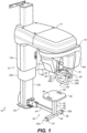
- Figure 1 illustrates an embodiment of an extra-oral imaging apparatus 10.
- Apparatus 10 comprises a support structure that includes a support frame 12 which is a support column.
- the column 12 may be adjustable in two or three dimensions.
- the column 12 can be telescopic and may include an upper part 12a that is slidably mounted over a fixed lower part 12b.
- the support structure also includes a horizontal mount 14 that may be supported or held by the vertical column 12.
- Horizontal mount 14 extends away from vertical column 12 and may be substantially perpendicular thereto.
- Horizontal mount 14 can move relative to the vertical column 12. More particularly, horizontal mount 14 is fixedly mounted on the vertical upper part 12a and is therefore movable therewith.
- an actuator e.g. of the electric type, located behind the vertical column (not represented in the drawing) can be commanded to drive the horizontal mount 14 into a vertical movement in a controlled manner.
- Horizontal mount 14 can support a gantry 16.
- Gantry 16 is movable relative to the support structure, and more particularly to horizontal mount 14.
- Gantry 16 may more particularly be rotatable relative to horizontal mount 14.
- Gantry 16 may be rotatable about a vertical axis of rotation, which may be still during the operation of the imaging process or may follow one among several predetermined trajectories, in accordance with the selected imaging process.
- a driving known mechanism (not represented) for driving the gantry 16 into a given movement is integrated inside horizontal mount 14.
- such driving mechanism includes motors for imparting a first movement in a X, Y plane, e.g. two step by step motors, and a motor for imparting a rotational movement about the vertical axis Z, e.g. a brushless motor.
- Gantry 16 supports both an x-ray source 18 and at least one x-ray sensor 20 that is arranged in correspondence with the x-ray source.
- X-ray source 18 and the at least one x-ray sensor 20 may be arranged facing each other.
- Gantry 16 may include two opposite downwardly extending arms: a first arm 16a supports x-ray source 18 that is attached thereto and a second opposite arm 16b supports the at least one x-ray sensor 20 that is attached thereto.
- x-ray source 18 When activated x-ray source 18 emits an x-ray beam which radiates all or part of an imaging area, e.g., a working area for placement of the patient's head, before impinging the at least one x-ray sensor 20.
- an imaging area e.g., a working area for placement of the patient's head
- the at least one x-ray sensor 20 may include a panoramic sensor, e.g. a slit-shaped sensor, a volumetric or computerized sensor (e.g. rectangular, square-shaped) or a cephalometric sensor or several sensors.
- a panoramic sensor e.g. a slit-shaped sensor, a volumetric or computerized sensor (e.g. rectangular, square-shaped) or a cephalometric sensor or several sensors.
- one or several operating modes or imaging processes (1, 2 or 3) may be used among the panoramic, volumetric or computerized tomography, and cephalometric modes.
- the support structure may also include a patient positioning arm 22 that is connected to the support frame, and more particularly to the vertical column 12.
- the patient positioning arm 22 is movable relative to the support frame. More particularly, arm 22 can slide along the vertical column 12 so as to move up or down upon command.
- the patient positioning arm 22 extends from an arm support 22a that is slidably mounted relative to the fixed lower part vertical column 12b.
- the patient positioning arm 22 extends along the apparatus in a direction that is substantially in correspondence with the direction of extension of horizontal mount 14.
- Patient positioning arm 22 is arranged sideways relative to the apparatus in a substantial parallel relationship with horizontal mount 14.
- an actuator e.g. of the electric type, located behind the vertical column (not represented in the drawing) can be commanded to drive the arm support 22a into a vertical movement in a controlled manner.
- Patient positioning arm 22 serves to position the patient in the apparatus at a given location.
- the patient positioning arm 22 can position the patient in the imaging area according to selection of an operating modes of the apparatus 10.
- Patient positioning arm 22 may include one or more patient positioning and/or holding systems generally located at a free end 22b of the arm or proximate thereto.
- One or more patient positioning and/or holding systems allow to position the anatomical structures of the patient's head according to different orientations and to immobilize the patient's head during the examination so as to reduce any possible movement.
- the arm 22 is configured to accommodate these systems.
- one of these systems includes two temporal holding members that extend upwardly from the arm 22 to which they are removably attached. Only one temporal holding member is represented, the other one being hidden by the arm 16b.
- a chin support 26 that extends upwardly from the arm 22 to which it is removably attached.
- the chin support 26 can be located between the two temporal holding members.
- a handle assembly 28 may be positioned at the free end 22b of the arm, underneath the arm and in a parallel relationship with the arm.
- This handle assembly 28 includes two vertical separate handle portions 28a, 28b which can be grasped by the patient when undergoing an imaging process so as to remain motionless.
- This handle assembly 28 has a U-shape which can include a horizontal base portion 28c and two vertical upwardly-extending branches 28a, 28b that are fixed to the arm 22. Each branch plays the role of a vertical handle portion.
- Patient positioning arm 22 also supports a monitor or display assembly 30 which makes it possible for a user of the apparatus to view and drive certain functions of the apparatus.
- the apparatus 10 further comprises a seat arrangement 40 that is connected to the support frame 12.
- the seat arrangement 40 is movable between at least two distinct positions:
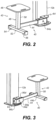
- Figures 2 and 3 illustrate two example different possible rest positions for the seat arrangement 40 (the remainder of the apparatus has not been represented by virtue of simplicity): the seat arrangement occupies two diametrically opposed rest positions that are preferably disposed at 180° one from another. However, other embodiments can envision an angle between rest positions greater than 180° or less than 180° (e.g., up to 270° or less than 90°).
- the working position in Figure 1 can be a median position relative to the two extreme symmetric rest positions. Alternatively, the angle between the working position and a desired rest position can be up to 180°. Also, the working position in Figure 1 can be an offset position closer to one or the two extreme symmetric rest positions.
- the seat arrangement 40 is located below the gantry 16 and the horizontal mount 14 and in parallel relationship therewith. In each of the two rest positions the seat arrangement 40 is no longer below gantry 16 and horizontal mount 14 and, for example, is at an angle of 90° to horizontal mount 14.
- Certain exemplary method and/or apparatus embodiments can reciprocally move the seat arrangement 40 repeatedly between various different positions described above.
- seat arrangement 40 is configured to pivot relative to the support frame 12 through a pivoting assembly to enable rotation of the seat arrangement between the different positions described above.
- the seat arrangement 40 may comprise a seat assembly 42 and a connecting arm 44.
- the seat assembly 42 may comprise a seat part 46 and a leg assembly 48 for ground support.
- Leg assembly 48 may comprise a vertical central supporting member 50 and a horizontal transverse member 52 which carries supporting member 50 and may be a bar.
- Transverse member 50 is provided at its two opposite ends 52a, 52b with pads 54 and 56 which are located under the transverse member and on the side opposite ends thereof. Pads 54 and 56 allow to keep the transverse member raised above the ground.
- the seat assembly 42 may comprise slots 58 and 60, e.g. elongated slots, that are formed through its thickness and located proximate its outer periphery. Slots 58 and 60 play the role of handling portions for manually handling the seat assembly 40 and moving it from the median working position of Figure 1 towards one of the two extreme rest positions of Figures 2 and 3 and the reverse. Slots 58, 60 may be arranged on two opposite sides of the seat assembly for handling the seat assembly more easily and conveniently.
- column 12 is supported at its lower end by a baseplate or supporting plate 62 and seat arrangement 40 is connected to baseplate 62 through the above-mentioned pivoting assembly.
- the fixed lower part 12b is coupled to baseplate 62.
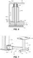
- connection of the seat arrangement 40 to the support frame 12 is further detailed on Figure 4 which is an enlarged view of the connecting zone in a longitudinal cross-section of the seat arrangement.
- a mounting bracket 64 is fixed to baseplate 62 through conventional permanent, fixed or re-attachable fastening members, e.g. screws, not represented here for the sake of clarity.
- Mounting bracket 64 has for example a C shape whose opening O is oriented opposite the column 12.
- Mounting bracket 64 comprises three portions: a middle portion 64a that is vertically oriented with its back to the column 12, a lower portion 64b that is horizontally oriented and rests against baseplate 62 to which it is fixed and an upper horizontal portion 64c facing the lower portion 64b. Both lower and upper portions 64b and 64c are adjacent the middle portion and conjointly define therewith the opening O.
- the above pivoting assembly is mounted in connection with mounting bracket 64 at one free end 40a of the seat arrangement 40 through a pivoting hollow axis 66 that is vertically disposed between the upper and lower portions 64c and 64b.
- Hollow axis 66 is fastened to upper and lower portions 64c and 64b through respective fastening members 68 and 70, e.g. screws.
- Fastening members 68 and 70 are respectively engaged into two threaded hollow ends of the axis 66 through the outside face of each of the upper and lower portions 64c and 64b.
- an indexed support or pad 72 is inserted between the seat arrangement end 40a and the upper face of the lower portion 64b and fixed to the latter.
- Indexed pad 72 comprises an indexed upper face 72a that is in contact with the seat arrangement end 40a in Figure 4 and is configured to include three distinct indexed positions that are represented from above in Figure 5 .
- Indexed upper face 72a is configured to include four raised portions each located at one of the four corners of the face: two separate raised portions 74b and 74c defining therebetween a first space S1 and two other separate raised portions 74d and 74e of greater dimensions defining therebetween a second reduced space S2.
- Raised portion 74b and larger raised portion 74d define therebetween a space S3 preferably of the same width as the second reduced space S2.
- Raised portion 74c and larger raised portion 74e define therebetween a space S4 preferably of the same width as the second reduced space S2.
- Spaces S2, S3 and S4 between the corresponding raised portions allow each to accommodate the seat arrangement end 40a in one of the three indexed positions each being in register with one of the working position and the two rest positions.
- seat arrangement end 40a occupies space S2 (more specifically, a portion of the lower face of end 40a lies in space S2 against face 72a) and extends to a location disposed between smaller raised portions 74b and 74c.
- Smaller raised portions 74b and 74c enable positioning of through holes 76, 78 therebetween while leaving sufficient room for accommodating seat arrangement end 40a in the working indexed position between holes 76, 78. These holes allow to accommodate fastening members (not represented for the sake of simplicity) for fastening indexed pad 72 to lower portion 64b.
- Figure 6 is an enlarged view in a transverse cross-section of the seat arrangement end 40a that has been moved from the working indexed position to the rest indexed position defined by space S3 of Figure 5 .
- Figure 6 illustrates beveled edges 74b1 and 74d1 of the respective raised portions 74b and 74d and end 40a is positioned between these beveled edges.
- a similar arrangement is provided for the other raised portions with beveled edges 74d2, 74e2, 74e1 and 74c1 located on either side of the corresponding space S2 and space S4.
- Each pair of beveled edges define together with the corresponding central space a groove in which end 40a can be positioned.
- Beveled edges make it easier the motion (e.g., rotary) of the end 40a from one indexed position towards another adjacent one.
- Beveled edges act as ramps that guide and help end 40a to leave the groove.
- Other known conventional edges, sides or transitions can be used to make easier the motion of the end 40a from one indexed position towards another adjacent one.
- the seat arrangement 40 is urged against indexed pad 72 through at least one elastic member 80.
- Elastic member 80 is disposed around a protruding end portion 66a of axis 66 that extends between end 40a and upper portion 64c. Elastic member 80 is maintained in this position in a compressed state, which biases the end 40a downwardly against the corresponding indexed position (working position in Figure 4 and a rest position in Figure 6 ).
- the seat arrangement is forcibly maintained in one of the three indexed positions thanks to elastic member 80.
- elastic member 80 may be a spring or an arrangement composed of several springs.
- the above seat arrangement and its moving mechanism provides a convenient and reliable arrangement to the apparatus. Thanks to this new arrangement the imaging process will be operated in reproducible or optimized conditions for the patients: the elderly and young patients will sit under the gantry during the process. This is also useful for tall persons who may encounter difficulties when standing under the gantry.
- the seat arrangement can be easily and quickly moved into a rest position so as to leave the working position unobstructed.
- FIG. 40 illustrates a specific configuration of the seat arrangement end 40a that is illustrated on Figures 1 to 4 .
- the seat arrangement 40 comprises a connecting member 90 that connects the connecting arm 44 to the support frame.
- the connecting arm 44 is not directly connected to the support frame and connecting member 90 longitudinally extends connecting arm 44.
- the connecting member 90 has, e.g. an elongated hollow shape, and two opposite ends:
- the second opposite end 44b of the connecting arm 44 is connected to the supporting member 50 of seat assembly 42 ( fig. 3 ).
- First end 90a is configured to enable insertion of the first end 44a of arm 44 inside the longitudinal hollow connecting member 90 and is temporary closed by a removably inserted plug 92.
- Plug 92 is perforated so as to be traversed by first end 44a.
- the connecting member 90 is in the form of a hollow casing which comprises five walls 90c-g illustrated on Figures 3 and 4 taken conjointly: an end vertical wall 90c that closes end 90b, two opposite upper and lower walls 90d and 90e and two opposite side walls 90f, 90g. Walls 90d-g conjointly define open end 90a that is closed by plug 92 and traversing arm 44.
- the first end 44a is connected to connecting member 90 through a horizontal pivot axis 94a about which first end 44a is pivotally mounted. Pivot axis 94a is inserted through perforations provided in walls 90f and 90g and end 44a and in register therewith.
- the first end 44a is also elastically mounted on an inner face 90e1 of lower wall 90e.
- First end 44a is configured to include a cavity 94 that is arranged transversally relative to the longitudinal axis of arm 44 and that is open at its two opposite lower and upper ends 94a, 94b.
- the cavity 94 is defined by a transverse wall 96 that extends over the whole height of the arm 44 and protrudes downwardly from the lower face of end 44a.
- a vertically-oriented rod 98 is rests against the inner lower face 90e1 and may be couple thereto.
- Rod 98 serves as a support axis for at least one elastic member 100 arranged around the rod.
- the at least one elastic member 100 and rod 98 are both housed inside cavity 94 and the at least one elastic member 100 is in a compressed state, thus urging first end 44a upwardly.
- the at least one elastic member 100 may, e.g. comprise a spring.
- An elastomer pad 102 is disposed on the outer face of upper portion 44a1 of first end 44a so as to serve as a mechanical stop against the inner face 90d1 of upper face 90d when connecting arm 44 is urged upwardly under specific conditions.
- Second end 90b of connecting member 90 includes a vertically-extending sheath 104 that is arranged between two upper and lower holes provided in the respective upper and lower walls 90d and 90e. Sheath 104 is fixed to walls 90d and 90e and surrounds axis 66.
- hole 94b is used for mounting arm end 44a inside connecting member 90.
- the mounting operation starts with insertion of elastic member 100 and rod 98 surrounded by elastic member inside cavity 94.
- a screw (not represented) is then inserted through hole 94b into the innerly threaded end 98a of rod 98.
- This temporary arrangement ties elastic member 100 and rod 98 together with arm 44, which makes it possible to longitudinally introduce arm 44 partially inside hollow connecting member 90.
- the arm is introduced to a longitudinal position where the perforations in walls 90f and 90g are in register with perforations in end 44a and a hole 106 provided in the upper wall 90d is in register with hole 94b. In this position the head 98b of rod 98 rests against inner face 90e1.
- Axis 94a is horizontally inserted through the corresponding perforations and fixedly mounted thereto so as to link arm 44 to connecting member 90 through a pivotally mounting. Also, the screw fixed into the threaded end 98a or rod 98 is unscrewed from above through hole 106. Elastic member 100 can then partially extend inside cavity 94 and urge end 44a upwardly. A plug 108 is next introduced into hole 106 to seal it.
- the position of the seat arrangement 40 illustrated in Figure 4 corresponds to the situation where a patient is on the seat part 46 of Figure 1 .
- This upper position of connecting arm 44 corresponds to a rest position for the arm in the absence of any patient on the seat assembly.
- a position is illustrated in Figure 7 where the seat arrangement 40 is still in an working indexed position.
- the arm 44 has pivoted upwardly about axis 94a which has caused an elevation of seat assembly 42 relative to the ground.
- the pads 54 and 56 are therefore no longer in contact with the ground.
- the arm 44 and connecting member or casing 90 are no longer parallel to each other.
- This elevated position of seat assembly 42 makes it easy for a user of the apparatus to manually rotate the seat arrangement about vertical. If the pads were still on the ground the user would have to raise the seat arrangement first before rotating it.
- FIG. 2 and 3 illustrate the seat arrangement 40 in each of the two rest indexed positions with the position of the arm 44 in the above-described rest position for Figure 7 . In each of these rest positions the seat arrangement 40 abuts against bracket 64 which prevents any further rotating motion.
- FIG. 8 to 13B show other possible pivoting seat arrangements that are integrated in an extra-oral dental imaging apparatus.
- the apparatus may be apparatus 10 of Figure 1 or an apparatus similar to and that comprises at least: a support frame and a gantry that supports an x-ray source and at least one x-ray sensor in correspondence with the x-ray source, the gantry being movable relative to the support frame.
- the apparatus will not be described any further in the following embodiments.
- each seat arrangement is connected to the support frame and is movable between at least two distinct positions: a working position and at least one rest position, e.g. two rest positions as described above with reference to Figures 1 to 7 .
- Figure 8 represents an apparatus 200 which comprises a seat arrangement 202 that is pivotally mounted relative to the support frame. All that has been described above for the pivoting assembly can apply here and will not be repeated.
- Seat arrangement 202 is pivotally mounted through a pivoting assembly 204 and comprises a seat assembly 206 as well as a connecting arm 208.
- Seat assembly 206 comprises a seat part 210 and a leg assembly 212 for ground support.
- Leg assembly 212 further comprises a vertical central member 214 and a baseplate 216, e.g. circular in shape.
- the seat arrangement 202 is also represented as 202' in a pivoted position after a 90° pivoting motion has been made from the working median position.
- Figure 9 represents an apparatus 220 having a seat arrangement 222 that is also pivotally mounted relative to the support frame through a pivoting assembly 224.
- Seat arrangement 222 comprises a seat assembly 226 as well as a connecting arm 228.
- Seat assembly 226 comprises a seat part 230 and a leg assembly 232 for ground support.
- Leg assembly 232 further comprises a vertical central member 234 and a baseplate 236.
- Baseplate 236 comprises two elongated portions 236a, 236b that are each coupled to vertical central member 234 at one of their two opposite ends. The two portions 236a, 236b extend outwardly away from each other so as to substantially form a V shape.
- Baseplase 236 thus configured offers a more stable ground support than baseplate 216 of Figure 8 .
- Seat part 230 is substantially square in shape and not circular as in Figure 8 .
- Seat part 230 also includes, in addition to an horizontal portion 230a forming the seat, a vertical downwardly extending portion 230b which serves as a support for the legs of the patient.
- Portion 230b has been recessed or partly removed in its middle part to make the seat part 230 lighter.
- Figure 10 illustrates a variant embodiment to Figure 10 in which only the seat arrangement 240 has been illustrated. This arrangement mainly differs from seat arrangement 222 in that:
- FIG 11 illustrates a variant embodiment to Figure 10 in which only the seat arrangement 250 has been illustrated.
- This arrangement mainly differs from seat arrangement 240 in that the baseplate 252 for ground support is a transverse member 254 mounted on casters 256, 258, e.g. in the number of two.
- the casters are disposed in alignment with member 254 which may take the form a rail oriented downwardly.
- the casters are mounted through mounting support members (not represented) located inside the rail. This arrangement provides further help for manually pivoting the seat arrangement.
- FIG 12 illustrates a further embodiment in which only the seat arrangement 260 has been illustrated in a deployed or unfolded position and in a retracted or folded position referred to as 260'.
- the seat arrangement 260 takes over some of the components of seat arrangement 202 in Figure 8 : the seat assembly 206 with its seat part 210, vertical member 214 and baseplate 216.
- the seat arrangement 260 comprises a connecting arm 262 that is an hinged arm.
- Hinged arm 262 includes two elongated portions 264, 266 that are linked together by a first hinge mechanism 268.
- Elongated portion 264 is connected to a support frame a member of which only 270 has been represented. This member may be attached to baseplate 62 of Figure 1 .
- Elongated portion 266 is connected to vertical member 214 of seat assembly 206.
- connections between the elongated portions 264, 266 and support frame 270 and seat assembly 206 respectively comprise second 272 and third 274 hinge mechanisms respectively.
- Each of the above three hinge mechanisms may be the same and may include a pivoting assembly of the same type as that of Figure 4 . Contrary to the pivoting assembly of Figure 4 , the pivot axis of each hinge mechanism is horizontal.
- the two elongated portions 264, 266 are in alignment to place the seat arrangement in the working position.
- the seat assembly 206 is pushed back by the user so that the two elongated portions 264, 266 can pivot relative to the three hinge mechanisms.
- Figures 13A and 13B illustrate a further embodiment of an apparatus 280 comprising a seat arrangement 282 of another type which is configured to move in 3D e.g., both pivot and translate, relative to the support frame 284.
- the seat arrangement comprises a seat assembly 286 with a seat part 288 coupled to a movable supporting structure 290 which is slidably mounted on a fixed rail structure 292.
- Movable supporting structure 290 includes side rollers which are located each between two elongated members defining a rail path therebetween closed at its two opposite ends and which serve as guide rails.
- Rail structure 292 is fixed to the support frame. More particularly, structure 290 includes two sets of two rollers 294a-d visible on Figures 13A-B and acts as a carriage. Each roller of each set is positioned inside a rail path defined by two elongated members 296a-b and 296c-d.
- the two pairs of elongated members 296a-b and 296c-d are transversally spaced apart from each other from a distance corresponding to the distance between the two rollers of each set.
- the two pairs of elongated members 296a-b and 296c-d are shaped so as to substantially take the form of a L in a lying position.
- the seat assembly 286 is therefore manually moved along the L-shaped path from the working position of Figure 13A to the rest position of Figure 13B where the seat assembly is in a vertical stowed away position.
- the members of the supporting structure 290 and fixed rail structure 290 may take the form of hollow cylindrical and curved tubes.
- FIG 14 illustrates a further embodiment in which only the seat arrangement 300 has been represented. This seat arrangement is similar to that of Figures 1 to 7 regarding the pivoting motion relative to the support frame of the apparatus.
- the seat arrangement 300 comprises a seat assembly 302 with a seat part 304 and a leg assembly 306 for ground support.
- Seat assembly 302 differs from seat assembly 42 of Figures 1 to 7 in the configuration of its seat part.
- Seat part 304 includes a horizontal portion 304a on which the patient sits and a downwardly extending portion 304b in the form of an S or inverted S (when viewed from the opposite side) when viewed laterally as seen on Figure 14 . It could also be considered that the upper part of the S- or S-inverted shape extends horizontally to form horizontal portion 304a.
- the lower part of the S- or S-inverted shape serves as a footrest for the patient sitting on the seat part.
- This configuration is asymmetrical as in Figures 10 and 11 since the patient can only sit according to one orientation.
- the other configurations make it possible for the patient to be oriented according to several orientations, in particular two 180° opposite orientations.
- Certain exemplary method and/or apparatus embodiments according to the application can provide exemplary seat arrangements that can reciprocally and repeatedly move between various different positions described above (e.g., at least one working position and at least one rest storage/rest position.
- Exemplary embodiments according to the application can include various features described herein (individually or in combination). Although embodiments of the present disclosure are illustrated using dental imaging apparatus, similar principles can be applied for other types of diagnostic imaging and for other anatomy.
Landscapes
- Health & Medical Sciences (AREA)
- Life Sciences & Earth Sciences (AREA)
- Medical Informatics (AREA)
- Engineering & Computer Science (AREA)
- Optics & Photonics (AREA)
- Biomedical Technology (AREA)
- Biophysics (AREA)
- High Energy & Nuclear Physics (AREA)
- Veterinary Medicine (AREA)
- Nuclear Medicine, Radiotherapy & Molecular Imaging (AREA)
- Public Health (AREA)
- Pathology (AREA)
- Radiology & Medical Imaging (AREA)
- Physics & Mathematics (AREA)
- Heart & Thoracic Surgery (AREA)
- Molecular Biology (AREA)
- Surgery (AREA)
- Animal Behavior & Ethology (AREA)
- General Health & Medical Sciences (AREA)
- Dentistry (AREA)
- Oral & Maxillofacial Surgery (AREA)
- Apparatus For Radiation Diagnosis (AREA)
Description
- The invention relates generally to the field of extra-oral dental x-ray imaging.
- A conventional extra-oral dental x-ray imaging apparatus generally comprises:
- a support frame
- a movable gantry that supports an x-ray source and an x-ray sensor in correspondence with the x-ray source and that is movable relative to the support frame.
- When the apparatus is being operated for obtaining a radiographic dental image of a patient's head, the patient is generally standing up under the gantry and positioned between the x-ray source and the x-ray sensor.
- The x-ray source is energized so as to generate an x-ray beam which radiates the teeth of the patient before impinging the x-ray sensor. The gantry is driven into motion and follows a given path according to the imaging process.
- For certain persons, such as elderly people and young patients, standing proves to be difficult.
- Also, for certain types of imaging process the head of the patient has to stay motionless while the imaging process is being operated.
- This is difficult for most people and even more problematic for the above-cited persons.
- It would then be desirable to provide an apparatus and a method that take into account the above.
-
US5692027 discloses an extra-oral dental x-ray imaging apparatus. - The invention is defined by the independent claims. It is an object of the present disclosure to advance the art of dental extra-oral imaging. Another object of this application is to address, in whole or in part, at least the foregoing and other deficiencies in the related art. It is another object of this application to provide, in whole or in part, at least the advantages described herein.
- According to an aspect an extra-oral dental imaging apparatus for obtaining a radiographic image of a patient, comprises:
- a support frame,
- a gantry that supports an x-ray source and at least one x-ray sensor in correspondence with the x-ray source, the gantry being movable relative to the support frame,
wherein the apparatus further comprises a seat arrangement that is connected to the support frame and that is movable between at least two distinct positions:- a working position in which the seat arrangement is located in a working area under the gantry,
- at least one rest position in which the seat arrangement is located away from the working area so as to leave clear the working area under the gantry.
- Certain exemplary method and/or apparatus embodiments can integrate a movable seat and makes it possible for patients to stay sitted on the seat in the working position during the whole imaging process. When the imaging process has come to an end or when the patient is able to do without the seat, the seat is moved into the at least one rest position. This is a simple and reliable arrangement of the apparatus.
- According to possible features:
- the seat arrangement comprises a seat assembly and a connecting arm;
- the seat assembly comprises a seat part and a leg assembly for ground support;
- the seat arrangement is configured to pivot relative to the support frame;
- the seat arrangement is configured to pivot relative to the support frame through a pivoting assembly;
- the support frame comprises an indexed face which includes at least two indexed positions corresponding to said at least two distinct positions of the seat arrangement respectively, the seat arrangement being configured to pivot relative to the indexed face through the pivoting assembly to move from one indexed position to another;
- the indexed face includes three indexed positions corresponding to three distinct positions of the seat arrangement respectively, namely the working position and two rest positions;
- the seat arrangement is urged against the indexed face through at least one elastic member;
- the seat arrangement comprises a connecting member that connects the connecting arm to the support frame, the connecting member being configured to pivot at one end relative to the indexed face through the pivoting assembly to move from one indexed position to another;
- the connecting member is connected at its opposite end to a first end of the connecting arm, the second opposite end of the connecting arm being connected to the seat assembly;
- the first end of the connecting arm is movably mounted relative to the connecting member in a vertical plane that includes the pivot axis of the pivoting assembly;
- the first end of the connecting arm is urged upwardly through at least one elastic member so that the connecting arm is urged in an upper rest position in the absence of any patient on the seat assembly;
- the first end of the connecting arm is pivotally mounted relative to the connecting member about a pivot axis that is perpendicular to the vertical plane;
- the seat arrangement is configured to both pivot and translate relative to the support frame (C4);
- the connecting arm is an hinged arm.
- According to another aspect, a method for using an extra-oral dental imaging apparatus for obtaining a radiographic image of a patient, comprises:
- a support frame,
- a gantry that supports an x-ray source and at least one x-ray sensor in correspondence with the x-ray source, the gantry being movable relative to the support frame,
- a seat arrangement that is connected to the support frame,
wherein the method comprises moving the seat arrangement between at least two distinct positions :- a working position in which the seat arrangement is located in a working area under the gantry,
- a rest position in which the seat arrangement is located away from the working area so as to leave clear the working area under the gantry.
- According to possible features:
- moving the seat arrangement comprises pivoting the seat arrangement relative to the support frame about a pivot axis;
- moving the seat arrangement further comprises translating the seat arrangement relative to the support frame;
- the seat arrangement comprises a seat assembly and a hinged connecting arm and moving the seat arrangement comprises folding or unfolding the hinged connecting arm.
- These objects are given only by way of illustrative example, and such objects may be exemplary of one or more embodiments of the invention. Other desirable objectives and advantages inherently achieved by the disclosed methods may occur or become apparent to those skilled in the art. The invention is defined by the appended claims.
- Other features and advantages will appear in the course of the remainder description, made by way of non-limiting examples, with reference to the following drawings:
-
Figure 1 depicts an overall schematic perspective view of an extra-oral imaging apparatus according to an embodiment of the invention; -
Figures 2 and 3 illustrate two rest positions of the seat arrangement ofFigure 1 ; -
Figure 4 is an enlarged partial longitudinal cross-section of the connection zone between the connecting arm of the seat arrangement ofFigure 1 and the support frame; -
Figure 5 is an enlarged top view of an indexed plate; -
Figure 6 is an enlarged partial transverse cross-section of the connection zone ofFigure 4 ; -
Figure 7 illustrates a median working position of the seat arrangement ofFigure 1 ; -
Figures 8 to 14 illustrate further possible embodiments of seat arrangements. -
Figure 1 illustrates an embodiment of an extra-oral imaging apparatus 10. Apparatus 10 comprises a support structure that includes asupport frame 12 which is a support column. Thecolumn 12 may be adjustable in two or three dimensions. For example, thecolumn 12 can be telescopic and may include anupper part 12a that is slidably mounted over a fixedlower part 12b. - The support structure also includes a
horizontal mount 14 that may be supported or held by thevertical column 12.Horizontal mount 14 extends away fromvertical column 12 and may be substantially perpendicular thereto.Horizontal mount 14 can move relative to thevertical column 12. More particularly,horizontal mount 14 is fixedly mounted on the verticalupper part 12a and is therefore movable therewith. For example, an actuator, e.g. of the electric type, located behind the vertical column (not represented in the drawing) can be commanded to drive thehorizontal mount 14 into a vertical movement in a controlled manner.Horizontal mount 14 can support agantry 16.Gantry 16 is movable relative to the support structure, and more particularly tohorizontal mount 14.Gantry 16 may more particularly be rotatable relative tohorizontal mount 14.Gantry 16 may be rotatable about a vertical axis of rotation, which may be still during the operation of the imaging process or may follow one among several predetermined trajectories, in accordance with the selected imaging process. A driving known mechanism (not represented) for driving thegantry 16 into a given movement is integrated insidehorizontal mount 14. By way of example, such driving mechanism includes motors for imparting a first movement in a X, Y plane, e.g. two step by step motors, and a motor for imparting a rotational movement about the vertical axis Z, e.g. a brushless motor. -
Gantry 16 supports both anx-ray source 18 and at least one x-ray sensor 20 that is arranged in correspondence with the x-ray source. X-raysource 18 and the at least one x-ray sensor 20 may be arranged facing each other.Gantry 16 may include two opposite downwardly extending arms: afirst arm 16a supportsx-ray source 18 that is attached thereto and a secondopposite arm 16b supports the at least one x-ray sensor 20 that is attached thereto. - When activated
x-ray source 18 emits an x-ray beam which radiates all or part of an imaging area, e.g., a working area for placement of the patient's head, before impinging the at least one x-ray sensor 20. - In the present embodiment, the at least one x-ray sensor 20 may include a panoramic sensor, e.g. a slit-shaped sensor, a volumetric or computerized sensor (e.g. rectangular, square-shaped) or a cephalometric sensor or several sensors.
- Depending on the sensor or sensors present in the apparatus, one or several operating modes or imaging processes (1, 2 or 3) may be used among the panoramic, volumetric or computerized tomography, and cephalometric modes.
- The support structure may also include a
patient positioning arm 22 that is connected to the support frame, and more particularly to thevertical column 12. Thepatient positioning arm 22 is movable relative to the support frame. More particularly,arm 22 can slide along thevertical column 12 so as to move up or down upon command. Thepatient positioning arm 22 extends from anarm support 22a that is slidably mounted relative to the fixed lower partvertical column 12b. Thepatient positioning arm 22 extends along the apparatus in a direction that is substantially in correspondence with the direction of extension ofhorizontal mount 14.Patient positioning arm 22 is arranged sideways relative to the apparatus in a substantial parallel relationship withhorizontal mount 14. For example, an actuator, e.g. of the electric type, located behind the vertical column (not represented in the drawing) can be commanded to drive thearm support 22a into a vertical movement in a controlled manner. -
Patient positioning arm 22 serves to position the patient in the apparatus at a given location. In one embodiment, thepatient positioning arm 22 can position the patient in the imaging area according to selection of an operating modes of the apparatus 10. -
Patient positioning arm 22 may include one or more patient positioning and/or holding systems generally located at afree end 22b of the arm or proximate thereto. - One or more patient positioning and/or holding systems allow to position the anatomical structures of the patient's head according to different orientations and to immobilize the patient's head during the examination so as to reduce any possible movement.
- There exists one or several systems for each type of examination to be carried out. The
arm 22 is configured to accommodate these systems. - As illustrated in
Figure 1 , one of these systems, noted 24, includes two temporal holding members that extend upwardly from thearm 22 to which they are removably attached. Only one temporal holding member is represented, the other one being hidden by thearm 16b. - Another illustrated system is a
chin support 26 that extends upwardly from thearm 22 to which it is removably attached. Thechin support 26 can be located between the two temporal holding members. - Other possible attachable, movable or integrated systems may be envisaged: a nasal support, a bite support etc.
- A
handle assembly 28 may be positioned at thefree end 22b of the arm, underneath the arm and in a parallel relationship with the arm. Thishandle assembly 28 includes two verticalseparate handle portions - Overall this
handle assembly 28 has a U-shape which can include ahorizontal base portion 28c and two vertical upwardly-extendingbranches arm 22. Each branch plays the role of a vertical handle portion. -
Patient positioning arm 22 also supports a monitor or displayassembly 30 which makes it possible for a user of the apparatus to view and drive certain functions of the apparatus. - The apparatus 10 further comprises a
seat arrangement 40 that is connected to thesupport frame 12. Theseat arrangement 40 is movable between at least two distinct positions: - a working position in which the
seat arrangement 40 is located in a working area with a prescribed spatial relationship to the thegantry 16 and the horizontal mount 14 (fig. 1 , e.g., below or under), - at least one rest position in which the
seat arrangement 40 is located away from the working area so as to leave clear the working area under thegantry 16. -
Figures 2 and 3 illustrate two example different possible rest positions for the seat arrangement 40 (the remainder of the apparatus has not been represented by virtue of simplicity): the seat arrangement occupies two diametrically opposed rest positions that are preferably disposed at 180° one from another. However, other embodiments can envision an angle between rest positions greater than 180° or less than 180° (e.g., up to 270° or less than 90°). The working position inFigure 1 can be a median position relative to the two extreme symmetric rest positions. Alternatively, the angle between the working position and a desired rest position can be up to 180°. Also, the working position inFigure 1 can be an offset position closer to one or the two extreme symmetric rest positions. InFigure 1 theseat arrangement 40 is located below thegantry 16 and thehorizontal mount 14 and in parallel relationship therewith. In each of the two rest positions theseat arrangement 40 is no longer belowgantry 16 andhorizontal mount 14 and, for example, is at an angle of 90° tohorizontal mount 14. - Certain exemplary method and/or apparatus embodiments can reciprocally move the
seat arrangement 40 repeatedly between various different positions described above. For example, in one embodiment,seat arrangement 40 is configured to pivot relative to thesupport frame 12 through a pivoting assembly to enable rotation of the seat arrangement between the different positions described above. - As depicted in
Figures 1 to 3 , theseat arrangement 40 may comprise aseat assembly 42 and a connectingarm 44. Theseat assembly 42 may comprise aseat part 46 and aleg assembly 48 for ground support.Leg assembly 48 may comprise a vertical central supportingmember 50 and a horizontaltransverse member 52 which carries supportingmember 50 and may be a bar.Transverse member 50 is provided at its twoopposite ends pads Pads - The
seat assembly 42 may compriseslots Slots seat assembly 40 and moving it from the median working position ofFigure 1 towards one of the two extreme rest positions ofFigures 2 and 3 and the reverse.Slots - More particularly,
column 12 is supported at its lower end by a baseplate or supportingplate 62 andseat arrangement 40 is connected to baseplate 62 through the above-mentioned pivoting assembly. The fixedlower part 12b is coupled tobaseplate 62. - The connection of the
seat arrangement 40 to thesupport frame 12 is further detailed onFigure 4 which is an enlarged view of the connecting zone in a longitudinal cross-section of the seat arrangement. - A mounting
bracket 64 is fixed tobaseplate 62 through conventional permanent, fixed or re-attachable fastening members, e.g. screws, not represented here for the sake of clarity. - Mounting
bracket 64 has for example a C shape whose opening O is oriented opposite thecolumn 12. Mountingbracket 64 comprises three portions: amiddle portion 64a that is vertically oriented with its back to thecolumn 12, alower portion 64b that is horizontally oriented and rests againstbaseplate 62 to which it is fixed and an upperhorizontal portion 64c facing thelower portion 64b. Both lower andupper portions - The above pivoting assembly is mounted in connection with mounting
bracket 64 at onefree end 40a of theseat arrangement 40 through a pivotinghollow axis 66 that is vertically disposed between the upper andlower portions Hollow axis 66 is fastened to upper andlower portions respective fastening members members axis 66 through the outside face of each of the upper andlower portions - More particularly, an indexed support or
pad 72 is inserted between theseat arrangement end 40a and the upper face of thelower portion 64b and fixed to the latter.Indexed pad 72 comprises an indexedupper face 72a that is in contact with theseat arrangement end 40a inFigure 4 and is configured to include three distinct indexed positions that are represented from above inFigure 5 . Indexedupper face 72a is configured to include four raised portions each located at one of the four corners of the face: two separate raisedportions portions portion 74b and larger raisedportion 74d define therebetween a space S3 preferably of the same width as the second reduced space S2. Raisedportion 74c and larger raisedportion 74e define therebetween a space S4 preferably of the same width as the second reduced space S2. - Spaces S2, S3 and S4 between the corresponding raised portions allow each to accommodate the
seat arrangement end 40a in one of the three indexed positions each being in register with one of the working position and the two rest positions. In the working positionseat arrangement end 40a occupies space S2 (more specifically, a portion of the lower face ofend 40a lies in space S2 againstface 72a) and extends to a location disposed between smaller raisedportions - Smaller raised
portions holes seat arrangement end 40a in the working indexed position between holes 76, 78. These holes allow to accommodate fastening members (not represented for the sake of simplicity) for fastening indexedpad 72 tolower portion 64b. -
Figure 6 is an enlarged view in a transverse cross-section of theseat arrangement end 40a that has been moved from the working indexed position to the rest indexed position defined by space S3 ofFigure 5 . -
Figure 6 illustrates beveled edges 74b1 and 74d1 of the respective raisedportions end 40a is positioned between these beveled edges. - A similar arrangement is provided for the other raised portions with beveled edges 74d2, 74e2, 74e1 and 74c1 located on either side of the corresponding space S2 and space S4. Each pair of beveled edges define together with the corresponding central space a groove in which
end 40a can be positioned. - Overall beveled edges make it easier the motion (e.g., rotary) of the
end 40a from one indexed position towards another adjacent one. Beveled edges act as ramps that guide and help end 40a to leave the groove. Other known conventional edges, sides or transitions can be used to make easier the motion of theend 40a from one indexed position towards another adjacent one. - As illustrated in
Figures 4 and6 , theseat arrangement 40 is urged against indexedpad 72 through at least oneelastic member 80.Elastic member 80 is disposed around aprotruding end portion 66a ofaxis 66 that extends betweenend 40a andupper portion 64c.Elastic member 80 is maintained in this position in a compressed state, which biases theend 40a downwardly against the corresponding indexed position (working position inFigure 4 and a rest position inFigure 6 ). Thus, the seat arrangement is forcibly maintained in one of the three indexed positions thanks toelastic member 80. By way of non-limiting example,elastic member 80 may be a spring or an arrangement composed of several springs. - The above seat arrangement and its moving mechanism provides a convenient and reliable arrangement to the apparatus. Thanks to this new arrangement the imaging process will be operated in reproducible or optimized conditions for the patients: the elderly and young patients will sit under the gantry during the process. This is also useful for tall persons who may encounter difficulties when standing under the gantry.
- Once the imaging process is terminated, the seat arrangement can be easily and quickly moved into a rest position so as to leave the working position unobstructed.
- All that has been described above regarding the pivoting assembly of the
seat arrangement 40 applies as well to a seat arrangement deprived of any specific configuration at its free end. Such a seat arrangement has only a connecting arm the end of which is arranged to be pivotally mounted aboutaxis 66. - A more detailed exemplary possible embodiment of the
seat arrangement 40 will now be described. This embodiment illustrates a specific configuration of theseat arrangement end 40a that is illustrated onFigures 1 to 4 . - In this respect, the
seat arrangement 40 comprises a connectingmember 90 that connects the connectingarm 44 to the support frame. In this embodiment the connectingarm 44 is not directly connected to the support frame and connectingmember 90 longitudinally extends connectingarm 44. In this embodiment, the connectingmember 90 has, e.g. an elongated hollow shape, and two opposite ends: - a
first end 90a that is configured to be connected to afirst end 44a ofarm 44; - a
second end 90b that is configured to be pivotally mounted relative to the indexedface 72a through the above-described pivoting assembly in order to move the connectingmember 90 and, therefore, thewhole seat arrangement 40, from one indexed position to another. - The second
opposite end 44b of the connectingarm 44 is connected to the supportingmember 50 of seat assembly 42 (fig. 3 ). -
First end 90a is configured to enable insertion of thefirst end 44a ofarm 44 inside the longitudinal hollow connectingmember 90 and is temporary closed by a removably insertedplug 92.Plug 92 is perforated so as to be traversed byfirst end 44a. - In the present embodiment, the connecting
member 90 is in the form of a hollow casing which comprises fivewalls 90c-g illustrated onFigures 3 and4 taken conjointly: an endvertical wall 90c that closesend 90b, two opposite upper andlower walls opposite side walls Walls 90d-g conjointly defineopen end 90a that is closed byplug 92 and traversingarm 44. - The
first end 44a is connected to connectingmember 90 through ahorizontal pivot axis 94a about whichfirst end 44a is pivotally mounted.Pivot axis 94a is inserted through perforations provided inwalls end 44a and in register therewith. - The
first end 44a, or a terminal portion of the arm proximate thefirst end 44a, is also elastically mounted on an inner face 90e1 oflower wall 90e.First end 44a is configured to include acavity 94 that is arranged transversally relative to the longitudinal axis ofarm 44 and that is open at its two opposite lower andupper ends cavity 94 is defined by atransverse wall 96 that extends over the whole height of thearm 44 and protrudes downwardly from the lower face ofend 44a. A vertically-orientedrod 98 is rests against the inner lower face 90e1 and may be couple thereto.Rod 98 serves as a support axis for at least oneelastic member 100 arranged around the rod. The at least oneelastic member 100 androd 98 are both housed insidecavity 94 and the at least oneelastic member 100 is in a compressed state, thus urgingfirst end 44a upwardly. The at least oneelastic member 100 may, e.g. comprise a spring. - An
elastomer pad 102 is disposed on the outer face of upper portion 44a1 offirst end 44a so as to serve as a mechanical stop against the inner face 90d1 ofupper face 90d when connectingarm 44 is urged upwardly under specific conditions. -
Second end 90b of connectingmember 90 includes a vertically-extendingsheath 104 that is arranged between two upper and lower holes provided in the respective upper andlower walls Sheath 104 is fixed towalls axis 66. - To be noted that
hole 94b is used for mountingarm end 44a inside connectingmember 90. The mounting operation starts with insertion ofelastic member 100 androd 98 surrounded by elastic member insidecavity 94. A screw (not represented) is then inserted throughhole 94b into the innerly threadedend 98a ofrod 98. This temporary arrangement tieselastic member 100 androd 98 together witharm 44, which makes it possible to longitudinally introducearm 44 partially inside hollow connectingmember 90. The arm is introduced to a longitudinal position where the perforations inwalls end 44a and ahole 106 provided in theupper wall 90d is in register withhole 94b. In this position thehead 98b ofrod 98 rests against inner face 90e1.Axis 94a is horizontally inserted through the corresponding perforations and fixedly mounted thereto so as to linkarm 44 to connectingmember 90 through a pivotally mounting. Also, the screw fixed into the threadedend 98a orrod 98 is unscrewed from above throughhole 106.Elastic member 100 can then partially extend insidecavity 94 and urgeend 44a upwardly. Aplug 108 is next introduced intohole 106 to seal it. - The position of the
seat arrangement 40 illustrated inFigure 4 corresponds to the situation where a patient is on theseat part 46 ofFigure 1 . - In this position the weight of the patient exerted on the connecting
arm 44 through the seat assembly maintainselastic member 100 in a fully compressed state inside itshousing 94. The seat assembly rests on the ground throughpads 54 and 56 (fig 1 ).Arm 44 is therefore in a lower and horizontal position and pad 102 is distant from the inner face 90d1 ofupper face 90d. I n thisposition connecting member 90 is further maintained against the indexedface 72a in the working indexed position thanks to the patient's weight. To be noted that, in the absence of a patient on the seat part,elastic member 80 is sufficiently sized to urge the connectingmember 90 downwardly against the indexedface 72a in the working indexed position or in any other rest indexed position. - When the patient stands up (the examination underwent by the patient has come to an end), the weight of the patient does no longer compensate for the upward force exerted by
elastic member 100. The latter then biases the connectingarm 44 upwardly. As theend 44a is pivotally mounted aboutpivot axis 94a, the upward movement ofarm 44 causes a pivoting motion thereof aboutaxis 94a andpad 102 abuts against inner face 90d1. The force exerted byelastic member 100 is not great enough to cause the connectingmember 90 to raise. - This upper position of connecting
arm 44 corresponds to a rest position for the arm in the absence of any patient on the seat assembly. Such a position is illustrated inFigure 7 where theseat arrangement 40 is still in an working indexed position. As represented, thearm 44 has pivoted upwardly aboutaxis 94a which has caused an elevation ofseat assembly 42 relative to the ground. Thepads Figure 7 , thearm 44 and connecting member orcasing 90 are no longer parallel to each other. This elevated position ofseat assembly 42 makes it easy for a user of the apparatus to manually rotate the seat arrangement about vertical. If the pads were still on the ground the user would have to raise the seat arrangement first before rotating it. In the elevated position the user can simply drive the seat arrangement into a rotating motion towards one of the two rest indexed positions ofFigures 2 and 3 so as to stow away theseat arrangement 40 in a location away from the working are ofFigure 1 . The rotating motion is made easy thanks to the beveled edges of the indexedface 72a which help connectingmember 90 to leave the groove in which it is positioned as explained above.Figures 2 and 3 illustrate theseat arrangement 40 in each of the two rest indexed positions with the position of thearm 44 in the above-described rest position forFigure 7 . In each of these rest positions theseat arrangement 40 abuts againstbracket 64 which prevents any further rotating motion. - Other embodiments illustrated in
Figures 8 to 13B show other possible pivoting seat arrangements that are integrated in an extra-oral dental imaging apparatus. The apparatus may be apparatus 10 ofFigure 1 or an apparatus similar to and that comprises at least: a support frame and a gantry that supports an x-ray source and at least one x-ray sensor in correspondence with the x-ray source, the gantry being movable relative to the support frame. The apparatus will not be described any further in the following embodiments. - Although the apparatus that integrates the seat arrangement is not always represented in the drawings of the following embodiments, it is to be understood as being implicitly part of the described embodiments. In the following embodiments each seat arrangement is connected to the support frame and is movable between at least two distinct positions: a working position and at least one rest position, e.g. two rest positions as described above with reference to
Figures 1 to 7 . -
Figure 8 represents anapparatus 200 which comprises aseat arrangement 202 that is pivotally mounted relative to the support frame. All that has been described above for the pivoting assembly can apply here and will not be repeated. -
Seat arrangement 202 is pivotally mounted through a pivotingassembly 204 and comprises aseat assembly 206 as well as a connectingarm 208.Seat assembly 206 comprises aseat part 210 and aleg assembly 212 for ground support.Leg assembly 212 further comprises a verticalcentral member 214 and abaseplate 216, e.g. circular in shape. Theseat arrangement 202 is also represented as 202' in a pivoted position after a 90° pivoting motion has been made from the working median position. -
Figure 9 represents anapparatus 220 having aseat arrangement 222 that is also pivotally mounted relative to the support frame through a pivotingassembly 224.Seat arrangement 222 comprises aseat assembly 226 as well as a connectingarm 228.Seat assembly 226 comprises aseat part 230 and aleg assembly 232 for ground support.Leg assembly 232 further comprises a verticalcentral member 234 and abaseplate 236.Baseplate 236 comprises twoelongated portions central member 234 at one of their two opposite ends. The twoportions Baseplase 236 thus configured offers a more stable ground support thanbaseplate 216 ofFigure 8 .Seat part 230 is substantially square in shape and not circular as inFigure 8 .Seat part 230 also includes, in addition to anhorizontal portion 230a forming the seat, a verticaldownwardly extending portion 230b which serves as a support for the legs of the patient.Portion 230b has been recessed or partly removed in its middle part to make theseat part 230 lighter. -
Figure 10 illustrates a variant embodiment toFigure 10 in which only theseat arrangement 240 has been illustrated. This arrangement mainly differs fromseat arrangement 222 in that: - the
baseplate 242 for ground support has a rectilinear shape substantially astransverse member 52 ofFigure 1 ; - vertical
central member 244 is axially shifted along thearm 246 towards the pivotingassembly 248 so as to be away frombaseplate 242. -
Figure 11 illustrates a variant embodiment toFigure 10 in which only theseat arrangement 250 has been illustrated. This arrangement mainly differs fromseat arrangement 240 in that thebaseplate 252 for ground support is atransverse member 254 mounted oncasters member 254 which may take the form a rail oriented downwardly. The casters are mounted through mounting support members (not represented) located inside the rail. This arrangement provides further help for manually pivoting the seat arrangement. -
Figure 12 illustrates a further embodiment in which only theseat arrangement 260 has been illustrated in a deployed or unfolded position and in a retracted or folded position referred to as 260'. Theseat arrangement 260 takes over some of the components ofseat arrangement 202 inFigure 8 : theseat assembly 206 with itsseat part 210,vertical member 214 andbaseplate 216. However, theseat arrangement 260 comprises a connectingarm 262 that is an hinged arm. Hingedarm 262 includes twoelongated portions first hinge mechanism 268.Elongated portion 264 is connected to a support frame a member of which only 270 has been represented. This member may be attached to baseplate 62 ofFigure 1 .Elongated portion 266 is connected tovertical member 214 ofseat assembly 206. - The connections between the
elongated portions support frame 270 andseat assembly 206 respectively comprise second 272 and third 274 hinge mechanisms respectively. - Each of the above three hinge mechanisms may be the same and may include a pivoting assembly of the same type as that of
Figure 4 . Contrary to the pivoting assembly ofFigure 4 , the pivot axis of each hinge mechanism is horizontal. - In an extended or deployed position the two
elongated portions - To switch between the extended position and a retracted or folded position the
seat assembly 206 is pushed back by the user so that the twoelongated portions - In the retracted or folded position the two elongated portions referred to as 264', 266' are placed one against the other in a substantially parallel relationship. With this configuration the seat assembly has thus been placed in a stowed away or rest position which leaves freed the working area under the gantry of the apparatus (not represented). This arrangement is more compact than the previous ones.
-
Figures 13A and 13B illustrate a further embodiment of anapparatus 280 comprising aseat arrangement 282 of another type which is configured to move in 3D e.g., both pivot and translate, relative to thesupport frame 284. - The seat arrangement comprises a
seat assembly 286 with aseat part 288 coupled to a movable supportingstructure 290 which is slidably mounted on a fixedrail structure 292. Movable supportingstructure 290 includes side rollers which are located each between two elongated members defining a rail path therebetween closed at its two opposite ends and which serve as guide rails.Rail structure 292 is fixed to the support frame. More particularly,structure 290 includes two sets of tworollers 294a-d visible onFigures 13A-B and acts as a carriage. Each roller of each set is positioned inside a rail path defined by twoelongated members 296a-b and 296c-d. The two pairs ofelongated members 296a-b and 296c-d are transversally spaced apart from each other from a distance corresponding to the distance between the two rollers of each set. The two pairs ofelongated members 296a-b and 296c-d are shaped so as to substantially take the form of a L in a lying position. Theseat assembly 286 is therefore manually moved along the L-shaped path from the working position ofFigure 13A to the rest position ofFigure 13B where the seat assembly is in a vertical stowed away position. Such an arrangement is convenient to use and provides a compact design. The members of the supportingstructure 290 and fixedrail structure 290 may take the form of hollow cylindrical and curved tubes. -
Figure 14 illustrates a further embodiment in which only theseat arrangement 300 has been represented. This seat arrangement is similar to that ofFigures 1 to 7 regarding the pivoting motion relative to the support frame of the apparatus. - The
seat arrangement 300 comprises aseat assembly 302 with aseat part 304 and aleg assembly 306 for ground support.Seat assembly 302 differs fromseat assembly 42 ofFigures 1 to 7 in the configuration of its seat part.Seat part 304 includes ahorizontal portion 304a on which the patient sits and a downwardly extendingportion 304b in the form of an S or inverted S (when viewed from the opposite side) when viewed laterally as seen onFigure 14 . It could also be considered that the upper part of the S- or S-inverted shape extends horizontally to formhorizontal portion 304a. The lower part of the S- or S-inverted shape serves as a footrest for the patient sitting on the seat part. - This configuration is asymmetrical as in
Figures 10 and11 since the patient can only sit according to one orientation. In contrast, the other configurations make it possible for the patient to be oriented according to several orientations, in particular two 180° opposite orientations. - Other possible seat arrangement embodiments may be envisaged within the scope of the invention.
- Certain exemplary method and/or apparatus embodiments according to the application can provide exemplary seat arrangements that can reciprocally and repeatedly move between various different positions described above (e.g., at least one working position and at least one rest storage/rest position. Exemplary embodiments according to the application can include various features described herein (individually or in combination). Although embodiments of the present disclosure are illustrated using dental imaging apparatus, similar principles can be applied for other types of diagnostic imaging and for other anatomy.
- While the invention has been illustrated with respect to one or more implementations, alterations and/or modifications can be made to the illustrated examples without departing from the scope of the appended claims. In addition, while a particular feature of the invention can have been disclosed with respect to only one of several implementations/embodiments, such feature can be combined with one or more other features of the other implementations/embodiments as can be desired and advantageous for any given or particular function. The term "at least one of' is used to mean one or more of the listed items can be selected. The term "about" indicates that the value listed can be somewhat altered, as long as the alteration does not result in nonconformance of the process or structure to the illustrated embodiment. Finally, "exemplary" indicates the description is used as an example, rather than implying that it is an ideal. Other embodiments of the invention will be apparent to those skilled in the art from consideration of the specification and practice of the invention disclosed herein. It is intended that the specification and examples be considered as exemplary only, with a true scope of the invention being indicated by at least the following claims.
Claims (16)
- An extra-oral dental imaging apparatus (10) for obtaining a radiographic image of a patient, the apparatus (10) comprising:- a support frame (12) being a support column,- a gantry (16) that supports an x-ray source (18) and at least one x-ray sensor (20) in correspondence with the x-ray source (18), the gantry (16) being movable relative to the support frame (12),
wherein the apparatus (10) further comprises a seat arrangement (40) that is movably connected to the support frame (12), enabling a rotational movement of the seat arrangement around the support frame, and that is movable between at least two distinct positions :a working position in which the seat arrangement (40) is located in a working area under the gantry (16),at least one rest position in which the seat arrangement (40) is located away from the working area so as to leave clear the working area under the gantry (16). - The dental imaging apparatus (10) of claim 1, wherein the seat arrangement (40) comprises a seat assembly (42) and a connecting arm (44).
- The dental imaging apparatus (10) of claim 1 or 2, wherein the seat assembly (42) comprises a seat part (46) and a leg assembly (48) for ground support.
- The dental imaging apparatus (10) of any of claims 1 to 3, wherein the seat arrangement (40) is configured to pivot relative to the support frame (12).
- The dental imaging apparatus (10) of claim 4, wherein the seat arrangement (40) is configured to pivot relative to the support frame (12) through a pivoting assembly.
- The dental imaging apparatus (10) of claim 5, wherein the support frame (12) comprises an indexed face (72a) which includes at least two indexed positions corresponding to said at least two distinct positions of the seat arrangement (40) respectively, the seat arrangement (40) being configured to pivot relative to the indexed face (72a) through the pivoting assembly to move from one indexed position to another.
- The dental imaging apparatus (10) of claim 6, wherein the indexed face (72a) includes three indexed positions corresponding to three distinct positions of the seat arrangement respectively, namely the working position and two rest positions.
- The dental imaging apparatus (10) of claim 6 or 7, wherein the seat arrangement (40) is urged against the indexed face (72a) through at least one elastic member (80).
- The dental imaging apparatus (10) of claim 2 or 3 and any of claims 6 to 8, wherein the seat arrangement (40) comprises a connecting member (90) that connects the connecting arm (44) to the support frame (12), the connecting member (90) being configured to pivot at one end relative to the indexed face (72a) through the pivoting assembly to move from one indexed position to another.
- The dental imaging apparatus (10) of claim 9, wherein the connecting member (90) is connected at its opposite end (90a, 90b) to a first end (44a) of the connecting arm (44), the second opposite end (44b) of the connecting arm (44) being connected to the seat assembly (42).
- The dental imaging apparatus (10) of claim 10, wherein the first end (44a) of the connecting arm (44) is movably mounted relative to the connecting member (90) in a vertical plane that includes the pivot axis (94a) of the pivoting assembly.
- The dental imaging apparatus (10) of claim 11, wherein the first end (44a) of the connecting arm (44) is urged upwardly through at least one elastic member (100) so that the connecting arm (44) is urged in an upper rest position in the absence of any patient on the seat assembly (42).
- The dental imaging apparatus (10) of claim 11 or 12, wherein the first end (44a) of the connecting arm (44) is pivotally mounted relative to the connecting member (90) about a pivot axis (94a) that is perpendicular to the vertical plane.
- The dental imaging apparatus (10) of any of claims 1 to 3, wherein the seat arrangement (40) is configured to both pivot and translate relative to the support frame (12).
- The dental imaging apparatus (10) of claim 2 or 3, wherein the connecting arm (44) is an hinged arm.
- A method for using an extra-oral dental imaging apparatus (10) for obtaining a radiographic image of a patient, the apparatus (10) comprising:- a support frame (12) being a support column,- a gantry (16) that supports an x-ray source (18) and at least one x-ray sensor (20) in correspondence with the x-ray source (18), the gantry (16) being movable relative to the support frame (12),- a seat arrangement (40) that is movably connected to the support frame (12), enabling a rotational movement of the seat arrangement around the support frame,a rest position in which the seat arrangement (40) is located away from the working area so as to leave clear the working area under the gantry (16).
wherein the method comprises moving the seat arrangement (40) between at least two distinct positions :
a working position in which the seat arrangement (40) is located in a working area under the gantry (16),
Applications Claiming Priority (1)
| Application Number | Priority Date | Filing Date | Title |
|---|---|---|---|
| PCT/IB2016/002001 WO2018115922A1 (en) | 2016-12-22 | 2016-12-22 | A dental imaging apparatus with an integrated movable seat arrangement |
Publications (2)
| Publication Number | Publication Date |
|---|---|
| EP3558130A1 EP3558130A1 (en) | 2019-10-30 |
| EP3558130B1 true EP3558130B1 (en) | 2024-02-28 |
Family
ID=58231653
Family Applications (1)
| Application Number | Title | Priority Date | Filing Date |
|---|---|---|---|
| EP16843260.7A Active EP3558130B1 (en) | 2016-12-22 | 2016-12-22 | A dental imaging apparatus with an integrated movable seat arrangement |
Country Status (7)
| Country | Link |
|---|---|
| US (1) | US11986335B2 (en) |
| EP (1) | EP3558130B1 (en) |
| JP (1) | JP6952782B2 (en) |
| KR (1) | KR20190094458A (en) |
| CN (1) | CN110290748A (en) |
| ES (1) | ES2975104T3 (en) |
| WO (1) | WO2018115922A1 (en) |
Families Citing this family (3)
| Publication number | Priority date | Publication date | Assignee | Title |
|---|---|---|---|---|
| CN109512453A (en) * | 2019-01-22 | 2019-03-26 | 青岛市口腔医院 | A kind of endodontic treatment CBCT filming apparatus |
| KR102722030B1 (en) * | 2022-08-25 | 2024-10-28 | 주식회사 덴티움 | Dental chair system |
| TWI828591B (en) * | 2023-05-30 | 2024-01-01 | 中臺科技大學 | X-ray auxiliary frame and its intelligent control system |
Family Cites Families (13)
| Publication number | Priority date | Publication date | Assignee | Title |
|---|---|---|---|---|
| GB657944A (en) * | 1948-08-20 | 1951-09-26 | Wyatt Bentley Childs | Dentist's chair |
| US4044265A (en) * | 1976-03-05 | 1977-08-23 | General Electric Company | Mobile chair for panoramic dental x-ray machine |
| US4229656A (en) * | 1978-10-31 | 1980-10-21 | Pfizer Inc. | X-ray orienting apparatus |
| JPH0411692Y2 (en) * | 1985-11-30 | 1992-03-24 | ||
| JPH0438811Y2 (en) * | 1987-04-11 | 1992-09-10 | ||
| JP3055839B2 (en) * | 1992-07-07 | 2000-06-26 | 株式会社吉田製作所 | Dental panoramic tomography device |
| DE4404640C1 (en) * | 1994-02-14 | 1995-02-09 | Siemens Ag | Dental X-ray diagnosis equipment for the preparation of panoramic films of the skull of a patient |
| JP3207073B2 (en) * | 1994-04-13 | 2001-09-10 | 株式会社モリタ製作所 | X-ray equipment |
| JP3023700U (en) * | 1995-10-12 | 1996-04-23 | 株式会社モリタ製作所 | X-ray equipment |
| JP3328689B2 (en) * | 2000-10-13 | 2002-09-30 | 株式会社吉田製作所 | Dental CCD camera |
| CN2456542Y (en) * | 2001-01-11 | 2001-10-31 | 温凤美 | Adjustable computer desk with seat |
| FI123978B (en) * | 2008-06-27 | 2014-01-15 | Planmeca Oy | dental Equipment |
| KR20100055975A (en) * | 2008-11-18 | 2010-05-27 | 주식회사바텍 | Dental x-ray ct photographing apparatus |
-
2016
- 2016-12-22 WO PCT/IB2016/002001 patent/WO2018115922A1/en not_active Ceased
- 2016-12-22 CN CN201680092105.1A patent/CN110290748A/en active Pending
- 2016-12-22 KR KR1020197021242A patent/KR20190094458A/en not_active Withdrawn
- 2016-12-22 JP JP2019534651A patent/JP6952782B2/en active Active
- 2016-12-22 ES ES16843260T patent/ES2975104T3/en active Active
- 2016-12-22 EP EP16843260.7A patent/EP3558130B1/en active Active
- 2016-12-22 US US16/472,469 patent/US11986335B2/en active Active
Also Published As
| Publication number | Publication date |
|---|---|
| US11986335B2 (en) | 2024-05-21 |
| US20210128088A1 (en) | 2021-05-06 |
| JP2020501844A (en) | 2020-01-23 |
| JP6952782B2 (en) | 2021-10-20 |
| ES2975104T3 (en) | 2024-07-03 |
| WO2018115922A1 (en) | 2018-06-28 |
| KR20190094458A (en) | 2019-08-13 |
| CN110290748A (en) | 2019-09-27 |
| EP3558130A1 (en) | 2019-10-30 |
Similar Documents
| Publication | Publication Date | Title |
|---|---|---|
| US12171591B2 (en) | Multi-directional x-ray imaging system | |
| US9962132B2 (en) | Multi-directional X-ray imaging system with single support column | |
| EP2861148B1 (en) | Vertical scan imaging system | |
| US5790996A (en) | Examination table for supporting and positioning a patient in a medical examination apparatus | |
| KR101611682B1 (en) | X-ray imaging apparatus capable of shooting multi photographing modes | |
| JPH02501445A (en) | For example, an examination chair that places a patient in a desired position for radiological examinations. | |
| CN105188542A (en) | Extremity imaging apparatus for cone beam computed tomography | |
| US11986335B2 (en) | Dental imaging apparatus with an integrated movable seat arrangement | |
| JPH087842Y2 (en) | X-ray CT system | |
| JP3640172B2 (en) | X-ray fluoroscopy table | |
| JPH04352948A (en) | X-ray computed tomography(ct) device | |
| KR102942516B1 (en) | CT imaging device | |
| CN107260201A (en) | Scanning bed and medical imaging device | |
| US10835441B2 (en) | Patient positioning apparatus with adjustable and lockable back rest | |
| US10524750B2 (en) | Scanning system | |
| JPH08275940A (en) | X-ray fluoroscopic photographing stand | |
| CN213046941U (en) | A suspended tomographic fusion X-ray machine | |
| JPH0438811Y2 (en) | ||
| JP2000037381A (en) | X-ray radiographing device | |
| JPH11104123A (en) | X-ray equipment | |
| HK40067240A (en) | Ct imaging apparatus | |
| HK40067239B (en) | Ct imaging apparatus | |
| HK40067239A (en) | Ct imaging apparatus | |
| HK40067237B (en) | Ct imaging apparatus | |
| HK40067236B (en) | Ct imaging apparatus |
Legal Events
| Date | Code | Title | Description |
|---|---|---|---|
| STAA | Information on the status of an ep patent application or granted ep patent |
Free format text: STATUS: UNKNOWN |
|
| STAA | Information on the status of an ep patent application or granted ep patent |
Free format text: STATUS: THE INTERNATIONAL PUBLICATION HAS BEEN MADE |
|
| PUAI | Public reference made under article 153(3) epc to a published international application that has entered the european phase |
Free format text: ORIGINAL CODE: 0009012 |
|
| STAA | Information on the status of an ep patent application or granted ep patent |
Free format text: STATUS: REQUEST FOR EXAMINATION WAS MADE |
|
| 17P | Request for examination filed |
Effective date: 20190709 |
|
| AK | Designated contracting states |
Kind code of ref document: A1 Designated state(s): AL AT BE BG CH CY CZ DE DK EE ES FI FR GB GR HR HU IE IS IT LI LT LU LV MC MK MT NL NO PL PT RO RS SE SI SK SM TR |
|
| AX | Request for extension of the european patent |
Extension state: BA ME |
|
| DAV | Request for validation of the european patent (deleted) | ||
| DAX | Request for extension of the european patent (deleted) | ||
| STAA | Information on the status of an ep patent application or granted ep patent |
Free format text: STATUS: EXAMINATION IS IN PROGRESS |
|
| 17Q | First examination report despatched |
Effective date: 20220518 |
|
| GRAP | Despatch of communication of intention to grant a patent |
Free format text: ORIGINAL CODE: EPIDOSNIGR1 |
|
| STAA | Information on the status of an ep patent application or granted ep patent |
Free format text: STATUS: GRANT OF PATENT IS INTENDED |
|
| INTG | Intention to grant announced |
Effective date: 20231019 |
|
| GRAS | Grant fee paid |
Free format text: ORIGINAL CODE: EPIDOSNIGR3 |
|
| GRAA | (expected) grant |
Free format text: ORIGINAL CODE: 0009210 |
|
| STAA | Information on the status of an ep patent application or granted ep patent |
Free format text: STATUS: THE PATENT HAS BEEN GRANTED |
|
| AK | Designated contracting states |
Kind code of ref document: B1 Designated state(s): AL AT BE BG CH CY CZ DE DK EE ES FI FR GB GR HR HU IE IS IT LI LT LU LV MC MK MT NL NO PL PT RO RS SE SI SK SM TR |
|
| REG | Reference to a national code |
Ref country code: GB Ref legal event code: FG4D |
|
| REG | Reference to a national code |
Ref country code: CH Ref legal event code: EP |
|
| REG | Reference to a national code |
Ref country code: DE Ref legal event code: R096 Ref document number: 602016086068 Country of ref document: DE |
|
| REG | Reference to a national code |
Ref country code: IE Ref legal event code: FG4D |
|
| REG | Reference to a national code |
Ref country code: LT Ref legal event code: MG9D |
|
| PG25 | Lapsed in a contracting state [announced via postgrant information from national office to epo] |
Ref country code: IS Free format text: LAPSE BECAUSE OF FAILURE TO SUBMIT A TRANSLATION OF THE DESCRIPTION OR TO PAY THE FEE WITHIN THE PRESCRIBED TIME-LIMIT Effective date: 20240628 |
|
| REG | Reference to a national code |
Ref country code: NL Ref legal event code: MP Effective date: 20240228 Ref country code: ES Ref legal event code: FG2A Ref document number: 2975104 Country of ref document: ES Kind code of ref document: T3 Effective date: 20240703 |
|
| PG25 | Lapsed in a contracting state [announced via postgrant information from national office to epo] |
Ref country code: LT Free format text: LAPSE BECAUSE OF FAILURE TO SUBMIT A TRANSLATION OF THE DESCRIPTION OR TO PAY THE FEE WITHIN THE PRESCRIBED TIME-LIMIT Effective date: 20240228 |
|
| PG25 | Lapsed in a contracting state [announced via postgrant information from national office to epo] |
Ref country code: GR Free format text: LAPSE BECAUSE OF FAILURE TO SUBMIT A TRANSLATION OF THE DESCRIPTION OR TO PAY THE FEE WITHIN THE PRESCRIBED TIME-LIMIT Effective date: 20240529 |
|
| PG25 | Lapsed in a contracting state [announced via postgrant information from national office to epo] |
Ref country code: RS Free format text: LAPSE BECAUSE OF FAILURE TO SUBMIT A TRANSLATION OF THE DESCRIPTION OR TO PAY THE FEE WITHIN THE PRESCRIBED TIME-LIMIT Effective date: 20240528 Ref country code: HR Free format text: LAPSE BECAUSE OF FAILURE TO SUBMIT A TRANSLATION OF THE DESCRIPTION OR TO PAY THE FEE WITHIN THE PRESCRIBED TIME-LIMIT Effective date: 20240228 Ref country code: NL Free format text: LAPSE BECAUSE OF FAILURE TO SUBMIT A TRANSLATION OF THE DESCRIPTION OR TO PAY THE FEE WITHIN THE PRESCRIBED TIME-LIMIT Effective date: 20240228 |
|
| PG25 | Lapsed in a contracting state [announced via postgrant information from national office to epo] |
Ref country code: RS Free format text: LAPSE BECAUSE OF FAILURE TO SUBMIT A TRANSLATION OF THE DESCRIPTION OR TO PAY THE FEE WITHIN THE PRESCRIBED TIME-LIMIT Effective date: 20240528 Ref country code: NO Free format text: LAPSE BECAUSE OF FAILURE TO SUBMIT A TRANSLATION OF THE DESCRIPTION OR TO PAY THE FEE WITHIN THE PRESCRIBED TIME-LIMIT Effective date: 20240528 Ref country code: NL Free format text: LAPSE BECAUSE OF FAILURE TO SUBMIT A TRANSLATION OF THE DESCRIPTION OR TO PAY THE FEE WITHIN THE PRESCRIBED TIME-LIMIT Effective date: 20240228 Ref country code: LT Free format text: LAPSE BECAUSE OF FAILURE TO SUBMIT A TRANSLATION OF THE DESCRIPTION OR TO PAY THE FEE WITHIN THE PRESCRIBED TIME-LIMIT Effective date: 20240228 Ref country code: IS Free format text: LAPSE BECAUSE OF FAILURE TO SUBMIT A TRANSLATION OF THE DESCRIPTION OR TO PAY THE FEE WITHIN THE PRESCRIBED TIME-LIMIT Effective date: 20240628 Ref country code: HR Free format text: LAPSE BECAUSE OF FAILURE TO SUBMIT A TRANSLATION OF THE DESCRIPTION OR TO PAY THE FEE WITHIN THE PRESCRIBED TIME-LIMIT Effective date: 20240228 Ref country code: GR Free format text: LAPSE BECAUSE OF FAILURE TO SUBMIT A TRANSLATION OF THE DESCRIPTION OR TO PAY THE FEE WITHIN THE PRESCRIBED TIME-LIMIT Effective date: 20240529 Ref country code: FI Free format text: LAPSE BECAUSE OF FAILURE TO SUBMIT A TRANSLATION OF THE DESCRIPTION OR TO PAY THE FEE WITHIN THE PRESCRIBED TIME-LIMIT Effective date: 20240228 Ref country code: BG Free format text: LAPSE BECAUSE OF FAILURE TO SUBMIT A TRANSLATION OF THE DESCRIPTION OR TO PAY THE FEE WITHIN THE PRESCRIBED TIME-LIMIT Effective date: 20240228 |
|
| PG25 | Lapsed in a contracting state [announced via postgrant information from national office to epo] |
Ref country code: PL Free format text: LAPSE BECAUSE OF FAILURE TO SUBMIT A TRANSLATION OF THE DESCRIPTION OR TO PAY THE FEE WITHIN THE PRESCRIBED TIME-LIMIT Effective date: 20240228 Ref country code: PT Free format text: LAPSE BECAUSE OF FAILURE TO SUBMIT A TRANSLATION OF THE DESCRIPTION OR TO PAY THE FEE WITHIN THE PRESCRIBED TIME-LIMIT Effective date: 20240628 |
|
| REG | Reference to a national code |
Ref country code: AT Ref legal event code: MK05 Ref document number: 1660456 Country of ref document: AT Kind code of ref document: T Effective date: 20240228 |
|
| PG25 | Lapsed in a contracting state [announced via postgrant information from national office to epo] |
Ref country code: SE Free format text: LAPSE BECAUSE OF FAILURE TO SUBMIT A TRANSLATION OF THE DESCRIPTION OR TO PAY THE FEE WITHIN THE PRESCRIBED TIME-LIMIT Effective date: 20240228 Ref country code: PT Free format text: LAPSE BECAUSE OF FAILURE TO SUBMIT A TRANSLATION OF THE DESCRIPTION OR TO PAY THE FEE WITHIN THE PRESCRIBED TIME-LIMIT Effective date: 20240628 Ref country code: PL Free format text: LAPSE BECAUSE OF FAILURE TO SUBMIT A TRANSLATION OF THE DESCRIPTION OR TO PAY THE FEE WITHIN THE PRESCRIBED TIME-LIMIT Effective date: 20240228 Ref country code: LV Free format text: LAPSE BECAUSE OF FAILURE TO SUBMIT A TRANSLATION OF THE DESCRIPTION OR TO PAY THE FEE WITHIN THE PRESCRIBED TIME-LIMIT Effective date: 20240228 |
|
| PG25 | Lapsed in a contracting state [announced via postgrant information from national office to epo] |
Ref country code: DK Free format text: LAPSE BECAUSE OF FAILURE TO SUBMIT A TRANSLATION OF THE DESCRIPTION OR TO PAY THE FEE WITHIN THE PRESCRIBED TIME-LIMIT Effective date: 20240228 |
|
| PG25 | Lapsed in a contracting state [announced via postgrant information from national office to epo] |
Ref country code: SM Free format text: LAPSE BECAUSE OF FAILURE TO SUBMIT A TRANSLATION OF THE DESCRIPTION OR TO PAY THE FEE WITHIN THE PRESCRIBED TIME-LIMIT Effective date: 20240228 |
|
| PG25 | Lapsed in a contracting state [announced via postgrant information from national office to epo] |
Ref country code: EE Free format text: LAPSE BECAUSE OF FAILURE TO SUBMIT A TRANSLATION OF THE DESCRIPTION OR TO PAY THE FEE WITHIN THE PRESCRIBED TIME-LIMIT Effective date: 20240228 Ref country code: CZ Free format text: LAPSE BECAUSE OF FAILURE TO SUBMIT A TRANSLATION OF THE DESCRIPTION OR TO PAY THE FEE WITHIN THE PRESCRIBED TIME-LIMIT Effective date: 20240228 |
|
| PG25 | Lapsed in a contracting state [announced via postgrant information from national office to epo] |
Ref country code: AT Free format text: LAPSE BECAUSE OF FAILURE TO SUBMIT A TRANSLATION OF THE DESCRIPTION OR TO PAY THE FEE WITHIN THE PRESCRIBED TIME-LIMIT Effective date: 20240228 |
|
| PG25 | Lapsed in a contracting state [announced via postgrant information from national office to epo] |
Ref country code: SK Free format text: LAPSE BECAUSE OF FAILURE TO SUBMIT A TRANSLATION OF THE DESCRIPTION OR TO PAY THE FEE WITHIN THE PRESCRIBED TIME-LIMIT Effective date: 20240228 |
|
| PG25 | Lapsed in a contracting state [announced via postgrant information from national office to epo] |
Ref country code: SM Free format text: LAPSE BECAUSE OF FAILURE TO SUBMIT A TRANSLATION OF THE DESCRIPTION OR TO PAY THE FEE WITHIN THE PRESCRIBED TIME-LIMIT Effective date: 20240228 Ref country code: SK Free format text: LAPSE BECAUSE OF FAILURE TO SUBMIT A TRANSLATION OF THE DESCRIPTION OR TO PAY THE FEE WITHIN THE PRESCRIBED TIME-LIMIT Effective date: 20240228 Ref country code: RO Free format text: LAPSE BECAUSE OF FAILURE TO SUBMIT A TRANSLATION OF THE DESCRIPTION OR TO PAY THE FEE WITHIN THE PRESCRIBED TIME-LIMIT Effective date: 20240228 Ref country code: EE Free format text: LAPSE BECAUSE OF FAILURE TO SUBMIT A TRANSLATION OF THE DESCRIPTION OR TO PAY THE FEE WITHIN THE PRESCRIBED TIME-LIMIT Effective date: 20240228 Ref country code: DK Free format text: LAPSE BECAUSE OF FAILURE TO SUBMIT A TRANSLATION OF THE DESCRIPTION OR TO PAY THE FEE WITHIN THE PRESCRIBED TIME-LIMIT Effective date: 20240228 Ref country code: CZ Free format text: LAPSE BECAUSE OF FAILURE TO SUBMIT A TRANSLATION OF THE DESCRIPTION OR TO PAY THE FEE WITHIN THE PRESCRIBED TIME-LIMIT Effective date: 20240228 Ref country code: AT Free format text: LAPSE BECAUSE OF FAILURE TO SUBMIT A TRANSLATION OF THE DESCRIPTION OR TO PAY THE FEE WITHIN THE PRESCRIBED TIME-LIMIT Effective date: 20240228 |
|
| REG | Reference to a national code |
Ref country code: DE Ref legal event code: R097 Ref document number: 602016086068 Country of ref document: DE |
|
| PLBE | No opposition filed within time limit |
Free format text: ORIGINAL CODE: 0009261 |
|
| STAA | Information on the status of an ep patent application or granted ep patent |
Free format text: STATUS: NO OPPOSITION FILED WITHIN TIME LIMIT |
|
| 26N | No opposition filed |
Effective date: 20241129 |
|
| PG25 | Lapsed in a contracting state [announced via postgrant information from national office to epo] |
Ref country code: SI Free format text: LAPSE BECAUSE OF FAILURE TO SUBMIT A TRANSLATION OF THE DESCRIPTION OR TO PAY THE FEE WITHIN THE PRESCRIBED TIME-LIMIT Effective date: 20240228 |
|
| REG | Reference to a national code |
Ref country code: DE Ref legal event code: R119 Ref document number: 602016086068 Country of ref document: DE |
|
| PG25 | Lapsed in a contracting state [announced via postgrant information from national office to epo] |
Ref country code: MC Free format text: LAPSE BECAUSE OF FAILURE TO SUBMIT A TRANSLATION OF THE DESCRIPTION OR TO PAY THE FEE WITHIN THE PRESCRIBED TIME-LIMIT Effective date: 20240228 |
|
| REG | Reference to a national code |
Ref country code: CH Ref legal event code: PL |
|
| PG25 | Lapsed in a contracting state [announced via postgrant information from national office to epo] |
Ref country code: LU Free format text: LAPSE BECAUSE OF NON-PAYMENT OF DUE FEES Effective date: 20241222 |
|
| REG | Reference to a national code |
Ref country code: BE Ref legal event code: MM Effective date: 20241231 |
|
| PG25 | Lapsed in a contracting state [announced via postgrant information from national office to epo] |
Ref country code: DE Free format text: LAPSE BECAUSE OF NON-PAYMENT OF DUE FEES Effective date: 20250701 |
|
| PG25 | Lapsed in a contracting state [announced via postgrant information from national office to epo] |
Ref country code: BE Free format text: LAPSE BECAUSE OF NON-PAYMENT OF DUE FEES Effective date: 20241231 |
|
| PG25 | Lapsed in a contracting state [announced via postgrant information from national office to epo] |
Ref country code: CH Free format text: LAPSE BECAUSE OF NON-PAYMENT OF DUE FEES Effective date: 20241231 |
|
| PG25 | Lapsed in a contracting state [announced via postgrant information from national office to epo] |
Ref country code: IE Free format text: LAPSE BECAUSE OF NON-PAYMENT OF DUE FEES Effective date: 20241222 |
|
| PGFP | Annual fee paid to national office [announced via postgrant information from national office to epo] |
Ref country code: GB Payment date: 20251113 Year of fee payment: 10 |
|
| PGFP | Annual fee paid to national office [announced via postgrant information from national office to epo] |
Ref country code: IT Payment date: 20251211 Year of fee payment: 10 |
|
| PGFP | Annual fee paid to national office [announced via postgrant information from national office to epo] |
Ref country code: FR Payment date: 20251111 Year of fee payment: 10 |
|
| PGFP | Annual fee paid to national office [announced via postgrant information from national office to epo] |
Ref country code: ES Payment date: 20260120 Year of fee payment: 10 |
|
| PG25 | Lapsed in a contracting state [announced via postgrant information from national office to epo] |
Ref country code: CY Free format text: LAPSE BECAUSE OF FAILURE TO SUBMIT A TRANSLATION OF THE DESCRIPTION OR TO PAY THE FEE WITHIN THE PRESCRIBED TIME-LIMIT Effective date: 20240228 |