EP3558078B1 - Brühvorrichtung zur herstellung eines getränks aus einer einportionenkapsel - Google Patents
Brühvorrichtung zur herstellung eines getränks aus einer einportionenkapsel Download PDFInfo
- Publication number
- EP3558078B1 EP3558078B1 EP17832567.6A EP17832567A EP3558078B1 EP 3558078 B1 EP3558078 B1 EP 3558078B1 EP 17832567 A EP17832567 A EP 17832567A EP 3558078 B1 EP3558078 B1 EP 3558078B1
- Authority
- EP
- European Patent Office
- Prior art keywords
- capsule
- brewing
- beverage
- needles
- brewing apparatus
- Prior art date
- Legal status (The legal status is an assumption and is not a legal conclusion. Google has not performed a legal analysis and makes no representation as to the accuracy of the status listed.)
- Active
Links
Images


Classifications
-
- A—HUMAN NECESSITIES
- A47—FURNITURE; DOMESTIC ARTICLES OR APPLIANCES; COFFEE MILLS; SPICE MILLS; SUCTION CLEANERS IN GENERAL
- A47J—KITCHEN EQUIPMENT; COFFEE MILLS; SPICE MILLS; APPARATUS FOR MAKING BEVERAGES
- A47J31/00—Apparatus for making beverages
- A47J31/40—Beverage-making apparatus with dispensing means for adding a measured quantity of ingredients, e.g. coffee, water, sugar, cocoa, milk, tea
- A47J31/407—Beverage-making apparatus with dispensing means for adding a measured quantity of ingredients, e.g. coffee, water, sugar, cocoa, milk, tea with ingredient-containing cartridges; Cartridge-perforating means
-
- A—HUMAN NECESSITIES
- A47—FURNITURE; DOMESTIC ARTICLES OR APPLIANCES; COFFEE MILLS; SPICE MILLS; SUCTION CLEANERS IN GENERAL
- A47J—KITCHEN EQUIPMENT; COFFEE MILLS; SPICE MILLS; APPARATUS FOR MAKING BEVERAGES
- A47J31/00—Apparatus for making beverages
- A47J31/24—Coffee-making apparatus in which hot water is passed through the filter under pressure, i.e. in which the coffee grounds are extracted under pressure
- A47J31/34—Coffee-making apparatus in which hot water is passed through the filter under pressure, i.e. in which the coffee grounds are extracted under pressure with hot water under liquid pressure
- A47J31/36—Coffee-making apparatus in which hot water is passed through the filter under pressure, i.e. in which the coffee grounds are extracted under pressure with hot water under liquid pressure with mechanical pressure-producing means
- A47J31/3666—Coffee-making apparatus in which hot water is passed through the filter under pressure, i.e. in which the coffee grounds are extracted under pressure with hot water under liquid pressure with mechanical pressure-producing means whereby the loading of the brewing chamber with the brewing material is performed by the user
- A47J31/3676—Cartridges being employed
- A47J31/369—Impermeable cartridges being employed
- A47J31/3695—Cartridge perforating means for creating the hot water inlet
-
- A—HUMAN NECESSITIES
- A47—FURNITURE; DOMESTIC ARTICLES OR APPLIANCES; COFFEE MILLS; SPICE MILLS; SUCTION CLEANERS IN GENERAL
- A47J—KITCHEN EQUIPMENT; COFFEE MILLS; SPICE MILLS; APPARATUS FOR MAKING BEVERAGES
- A47J31/00—Apparatus for making beverages
- A47J31/24—Coffee-making apparatus in which hot water is passed through the filter under pressure, i.e. in which the coffee grounds are extracted under pressure
- A47J31/34—Coffee-making apparatus in which hot water is passed through the filter under pressure, i.e. in which the coffee grounds are extracted under pressure with hot water under liquid pressure
- A47J31/36—Coffee-making apparatus in which hot water is passed through the filter under pressure, i.e. in which the coffee grounds are extracted under pressure with hot water under liquid pressure with mechanical pressure-producing means
- A47J31/3604—Coffee-making apparatus in which hot water is passed through the filter under pressure, i.e. in which the coffee grounds are extracted under pressure with hot water under liquid pressure with mechanical pressure-producing means with a mechanism arranged to move the brewing chamber between loading, infusing and ejecting stations
- A47J31/3623—Cartridges being employed
- A47J31/3628—Perforating means therefor
Definitions
- the present invention relates to a brewing apparatus for preparing a beverage from a single-serve capsule containing a dose of infusible or soluble material, such as coffee, tea, chocolate, milk, etc.
- the present invention relates to a brewing apparatus for use in automatic machines for producing beverages from capsules designed to be perforated, at the beginning of a dispensing cycle, by perforating means carried by said brewing apparatus to allow a brewing fluid to be injected into the capsule.
- the market currently offers various types of capsules which differ from one another both physically in their shape, size and internal structure, and functionally, that is, in terms of the characteristics that the brewing process must have so that, having regard to the structure of the capsule and to the type, quantity and grain size of the material contained therein, the beverage produced has the desired characteristics.
- certain beverages require the respective capsules to be extracted by means of a high-pressure brewing process, in which the brewing fluid is fed into the capsule at a relatively low flow rate and relatively high speed, whereas other beverages require the respective capsules to be extracted by means of a low-pressure brewing process, in which the brewing fluid is fed into the capsule at a relatively high flow rate and relatively low speed.
- WO 2016/142157 A1 relates to a device for preparing beverages from a capsule.
- the device comprises capsule opening means designed to interact with an injection face of the capsule and comprise a liquid injection needle, a gas injection needle, and activation means designed to sequentially move the liquid injection needle and the gas injection needle to a position of interaction with the injection face of the capsule.
- the purpose of the present invention is to provide a brewing apparatus, which is a simple and economical alternative to the known solutions mentioned above.
- a brewing apparatus is provided as claimed in claim 1 and, preferably, in any one of the subsequent claims depending directly or independently on claim 1.
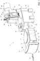
- FIG. 1 denoted as a whole by reference numeral 1 is a brewing apparatus suitable for use in an automatic machine for producing beverages by injecting a brewing fluid, typically pressurized hot water, into single-serve capsules containing a dose of infusible or soluble material, for example coffee, tea, chocolate, milk, etc.
- a brewing fluid typically pressurized hot water
- the brewing apparatus 1 is structured to implement the automatic brewing process starting from capsules 2 of the (known) type comprising a container designed to be perforated, in use, by perforating means borne by the brewing apparatus 1 to permit the injection of the brewing fluid into said capsule 2.
- the brewing apparatus 1 is configured to permit the use, in the same automatic machine, of capsules 2 that are identical to one another as far as their geometry and outside dimensions are concerned, but differ for the material they contain in terms of form, compactness and quantity, and for their internal structure.
- the accompanying figures illustrate a capsule 2 of the type described above, which comprises a cup-shaped body with a beverage outflow aperture 3 at the bottom, and a cover 4, which is seal-welded to an annular flange 5 on the outside of the cup-shaped body and consists of a perforable membrane, preferably obtained from a single or multi-layer sheet of plastic and/or metal material.
- the cup-shaped body is made of a waterproof plastic material, preferably obtained by thermoforming a material with oxygen and moisture barrier properties such as PP-EVOH-PP, for example, or by means of injection moulding with Polypropylene (PP) or Polybutylene terephthalate (PBT), and houses a filtering element 6, which divides the inside of the capsule 2 into an upper chamber containing the infusible material and a lower chamber communicating with the beverage outflow aperture 3.
- the capsule 2 is further provided with a sealing film 7 connected to an inside surface of the cup-shaped body to seal the outflow aperture 3 and which is designed to be perforated, following an axial compression of the capsule 2 and the subsequent collapsing of the cup-shaped body, by a tip 8 borne by the filtering element 6.
- the capsule 2 may be produced, as known in the prior art, in different versions depending on the type of beverage it is to produce.
- the different versions of the capsule 2 differ for the addition or absence of certain components inside the capsule 2 and, in general, can be grouped into two categories according to the type of brewing process required to obtain the respective beverages.
- a first category comprises capsules that require a high-pressure brewing process, in which the injection fluid is fed into said capsule at a relatively low flow rate and relatively high speed. Capsules of this type are used, for example, to produce espresso coffee or soluble beverages.
- a second category comprises capsules that require a low-pressure brewing process, in which the injection fluid is fed into said capsule at a relatively high flow rate and relatively low speed.
- Capsules of this type are used, for example, to produce so-called "Americano" coffee, or tea and other infusions.
- the inside structure may vary according to the beverage that the capsule 2 is to produce.
- the openings in the filtering element 6 may have different shapes and sizes; there may be a barrier element consisting of one or more superimposed membranes, possibly pre-cut, welded to the lower surface of the filtering element 6 to improve the pre-brewing of the material; the sealing film 7 may be missing or may be replaced with a manually removable external film.
- the capsule 2 may comprise ( Figure 6 ) a micro-perforated sheet 9 arranged in the upper chamber at a certain distance from the cover 5 to define an empty space between the material and the cover 4 and, in use, aid the uniform distribution of the brewing fluid.
- the brewing apparatus 1 comprises a frame 10, designed to be fixed to the inside of a casing (not illustrated) of the automatic machine, and a capsule holder 11 provided with a cavity 12 configured to receive a capsule 2.
- the frame 10 comprises an upper portion 13, which supports a water injection unit 14, and a lower portion 15, which defines a seat 16 suitable to be removably engaged by the capsule holder 11 to support it in a brewing position under the injection unit 14.
- the capsule holder 11 which will be described in detail later on in this document, is designed as a drawer able to slide in an insertion/extraction direction 17 (indicated by a double arrow in Figure 1 ) between an extracted loading position, in which the capsule holder 11 is outside the seat 16 to allow a user to remove an empty capsule 2 from the cavity 12 and load a new capsule 2 ( Figure 1 ), and said brewing position, in which the capsule holder 11 is fully inserted into the seat 16 ( Figure 4 ).
- the capsule holder 11 can be detached from the frame 10.
- the capsule holder 11 may only be partially extracted from the seat 16 provided this is sufficient to allow the user to access the cavity 12 to load or remove a capsule 2.
- the seat 16 has an entrance 18 and is defined by a substantially horizontal upper wall 19 and by two substantially vertical side walls 20, parallel to one another and to the direction 17 and provided with respective lower edges 21, which are bent towards one another and towards the inside of the seat 16 so as to define, with the respective side walls 20, a straight guide suitable to be engaged in a sliding manner by the capsule holder 11 in the direction 17.
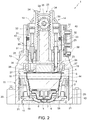
- the seat 16 is bounded by a transverse wall 22 ( Figure 3 ), which joins the side walls 20 to one another and defines a stop member to stop the capsule holder 11, when the latter is inserted into the seat 16, in a given position with respect to the injection unit 14, that is to say, in said brewing position.
- the cavity 12 in the capsule holder 11 faces a cup-shaped gasket 23, which is firmly inserted in a cavity provided in the upper wall 19, with its concave side facing downwards, and has an annular end lip designed to couple, in use, with the cover 4 of a capsule 2, roughly at the respective flange 5, to define a radial seal around a central area of the cover 4 to be perforated to allow the pressurized hot water to be fed into the capsule 2.
- the injection unit 14 comprises a needle injection device 24, an actuator device 25 to operate the needle injection device 24, and water feeding means to supply water at a given pressure to the needle injection device 24.
- the needle injection device 24 comprises a pair of hollow needles 26 and 27, which are supported by the upper portion 13 of the frame 10 above the cup-shaped gasket 23 and each of which is movable in a vertical direction between a respective normal rest position, in which the needle is retracted and does not protrude beyond the cup-shaped gasket 23, and a respective operating position, in which the needle is in a forward position and protrudes beyond the cup-shaped gasket 23 in order to penetrate the cover 4 of a capsule 2 arranged in the capsule holder 11 in the brewing position to inject the pressurized hot water into said capsule 2.
- the injection unit 14 is dimensioned in such a way that the needles 26 and 27 are able to supply respective different water flow rates to the capsule 2.
- the needles 26 and 27 have different inside diameters to one another and are selectively operated according to the type of capsule 2 to be processed.
- the water supply means comprise a single fixed displacement pump fluidically connected to both of the needles 26 and 27 to supply water to the respective needles 26 and 27 at the same flow rate.
- the pump is a variable displacement pump in order to supply water to the respective needles 26 and 27 at different flow rates.
- the water supply means comprise two fixed or variable displacement pumps, each of which is fluidically connected to a respective needle 26 and 27 to supply water to the needle in the operating position at a given flow rate.
- the needles 26 and 27 are kinematically connected to the actuator device 25 by means of a transmission 28 configured so as to make only one of the two needles 26 and 27 operational, in each delivery cycle, by moving said needle from the respective rest position to the respective operating position.
- the transmission 28 is a mechanical transmission and the actuator device 25 that operates it comprises an electric motor 29 connected to an electronic control unit (not illustrated) and has a power output shaft 30 able to rotate about an axis parallel to the direction 17.
- the transmission 28 comprises two sliding blocks 31, each of which carries a respective needle 26, 27 in a rigidly coupled manner and is defined by a tubular generally cylindrical body slidingly mounted in a respective guide channel 32 obtained in the upper portion 13 of the frame 10 and open towards the seat 16.
- Each sliding block 31 has an axial duct 33, which comprises a widened upper portion, suitable to be engaged by a connection (not illustrated) for coupling to a delivery pipe of the water pump (not illustrated), and a widened lower position engaged, preferably in a detachable manner, by an axial end of the respective needle 26, 27.
- the two sliding blocks 31 are arranged on opposite sides of the shaft 30 of the motor 29 and comprise respective toothed flat upper portions, which define respective racks 34 facing and parallel to one another and both meshing with a pinion 35 splined to the shaft 30 and which is part of the transmission 28.
- the needles 26 and 27 are both constantly coupled to the transmission 28 and the displacement of one of the two corresponds to a simultaneous displacement of the other of the same magnitude and in the opposite direction.
- the "operational" needle is moved from the normal rest position to the operating position, the other needle is moved from the normal rest position to a retracted waiting position by performing an equal and opposite displacement with respect to that of the "operational" needle.
- each needle 26, 27 is axially aligned with a respective tubular appendix 36 of the cup-shaped gasket 23, said appendix extending downwards, from a bottom wall of the cup-shaped gasket 23, up to, and preferably slightly beyond, the annular end lip of said cup-shaped gasket 23.
- Each tubular appendix 36 is suitable to be slidingly engaged by the respective needle 26, 27 when the latter moves to the extracted operating position, and is shaped and dimensioned to fluid-tightly couple with the external surface of the part of needle that axially engages it.
- tubular appendages 36 have respective ends 37 which, when the capsule 2 is fluid-tightly coupled to the cup-shaped gasket 23 ( Figure 4 ), are pressed against the cover 4 and define respective annular seals suitable to prevent any water or beverage that has come out of the hole made by the "operational" needle and on to the cover 4 from entering the tubular appendages 36 and possibly reaching the channels 32.
- the cup-shaped gasket 23 internally houses an abutment element 38 rigidly connected to the frame 10 ( Figure 3 ) and bounded at the bottom by a surface that is rounded towards the bottom, which, when the capsule 2 is pressed against the cup-shaped gasket 23, engages the central portion of the cover 4 and pushes it inwardly into the capsule 2 to such an extent as to stretch said cover 4.
- each end 37 is inclined with respect to the longitudinal axis of the respective tubular appendage 36 at an angle such as to complement the curvature of the cover 4 in the connection area and adhere to the cover 4 in an effective manner.
- Figure 2 illustrates the rest position of the needle 26, which is the needle with the larger inside diameter capable of delivering water at a higher flow rate than the needle 27, and the rest position of the needle 27, which is the needle with the smaller inside diameter and delivers a lower flow rate.
- the needles 26 and 27 may be arranged, according to their length, completely inside the respective channels 32 (as is the case of the needle 27 in the example that is illustrated) or protrude from the respective channel 32 and engage a first section of the respective tubular appendage 36 (as is the case of the needle 26 in the example that is illustrated), but without extending, in any case, beyond the end 37 of said tubular appendage 36.
- Figure 5 illustrates the configuration of the needle injection device 24 when the needle 26 is in the extracted operating position and, consequently, the needle 27 is in its retracted waiting position.
- needles like the needle 26, which supply a high flow rate and at low speed are used for capsules 2 designed to produce beverages that have to be extracted at low pressure, for example infusions or Americano-type coffee; such capsules do not normally have the aforesaid micro-perforated sheet 9.
- needles of this type are normally made to penetrate the capsule 2 relatively deeply so as to inject water directly into the dose of material to be brewed.
- the needle 26 comprises a hollow cylindrical stem, a solid tip cut obliquely, and a water outlet on the side facing the centre of the capsule 2 in order to facilitate the circulation of the water through the material to be brewed.
- Figure 6 illustrates the configuration of the needle injection device 24 when the needle 27 is in the extracted operating position and, consequently, the needle 26 is in the retracted waiting position.
- needles like the needle 27, which supply a low flow rate and at high speed, are used for capsules 2 designed for producing beverages that have to be extracted at high pressure, for example espresso coffee; such capsules are normally provided with the aforesaid micro-perforated sheet 9 which has the function of distributing the water and ensuring that it penetrates the material in a uniform manner.
- the needle 27 comprises a hollow cylindrical stem with a thin tip portion and an axial opening through which the water flows out.
- the selective activation of the needles 26 and 27 is controlled by the electronic control unit (not illustrated), which, depending on the type of capsule 2 inserted by a user, that is, according to the type of beverage to be produced, drives the motor 29 in one direction or the other in order to bring one of the two needles to perforate the capsule 2.
- the time for which the motor 29 is driven and, thus, the length of the displacement of the "operational" needle 26 or 27 from the rest position to the extracted operating position, is controlled by the electronic control unit (not illustrated) on the basis of signals sent to said electronic unit by sensor means designed to detect the axial position of the sliding blocks 31 along the respective guide channels 32.
- said sensor means consist, for example, of a Hall effect sensor 39 (of the conventional type) mounted on the upper portion 13 of the frame 10 and coupled to magnets 40 mounted on the sliding blocks 31.
- the transmission 28 could be different from that illustrated, for example it could consist of a mechanical linkage transmission or a hydraulic transmission.
- the transmission 28 could be configured to move, each time, only the needle selected to perforate the capsule, leaving the other needle stationary in the respective rest position.
- the displacements of the needles 26 and 27 could be controlled on the basis of sensors other than the Hall effect sensor described above, for example by using an encoder coupled to the shaft 30 of the electric motor 29 or a hydraulic system or any other system suitable for the purpose.
- the capsule holder 11 is designed as a drawer able to slide in the insertion/extraction direction 17 between an extracted loading position, in which a capsule 2 can be loaded into/removed from the cavity 12, and a brewing position, in which the capsule holder 11 is inserted into the seat 16 in the frame 10 and the cavity 12, with the capsule 2 that has been inserted, is arranged underneath and in a position coaxial to the cup-shaped gasket 23.
- the capsule holder 11 is also configured to move the capsule 2 from and towards a fluid-tight coupling position with said cup-shaped gasket 23.
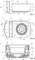
- the capsule holder 11 comprises a main body 41, which has a longitudinal axis 42 that is parallel to the direction 17 of insertion/extraction when the capsule holder 11 is inserted into the seat 16, and comprises a lower portion 43 and an upper portion 44, which engages the top of the lower portion 43, is provided with the cavity 12 and is slidingly coupled to the lower portion 43 so as to move, with respect to said lower portion 43, in a vertical direction between a lowered position, in which the cavity 12 is arranged inside the lower portion 43 ( Figures 9 and 10 ) and a raised position, in which the cavity is partially extracted from the lower portion 43 ( Figures 14 and 15 ).
- the lower portion 43 is generally cup shaped and comprises a bottom wall 45 and a side wall comprising, in turn, two longitudinal walls 46 arranged on opposite sides of the axis 42 and two transverse walls 47 perpendicular to the longitudinal walls 46.
- the upper portion 44 comprises an upper wall 48, which has a generically rectangular shape, has a sunken central part open at the bottom and defining the cavity 12, and is provided, along its periphery, with an annular edge 49 that extends downwards perpendicularly to the upper wall 48 and slidingly engages an inside surface of the side wall of the lower portion 43.
- the upper portion 44 is guided vertically onto the lower portion 43 by means of three pins 50 borne by the upper portion 44 and slidingly engaged in corresponding sleeves 51 rigidly coupled to the lower portion 43.
- the upper portion 44 is normally held in said lowered position by elastic means defined by three coil springs 52 (only one of which is visible in Figures 10 and 15 ), each of which is wound about a respective pin 50 and is interposed between one end of said pin 50 and the respective sleeve 51 in order to normally keep the upper portion 44 in the lowered position in contact with the lower portion 43 and to be compressed when the upper portion 44 is raised with respect to the lower portion 43.
- the capsule holder 11 further comprises a handle 53 connected to the main body 41 by means of two elongated elements 54, which are rigidly coupled to the handle 53, are parallel to the axis 42 and arranged on opposite sides of said axis 42, and engage in an axially sliding manner respective openings obtained through a transverse wall 47 of the lower portion 43 so as to allow the handle 53 to slide between a position at a distance from the main body 41 ( Figures 7 and 8 ) and a position close to the main body 41 ( Figures 12 and 13 ).
- the movement of the handle 53 with respect to the main body 41 determines the activation of a transmission device 55 designed to convert the horizontal rectilinear displacement of the handle 53 between the spaced position and the close position into a vertical rectilinear displacement of the upper portion 44 between the aforesaid lowered position and raised position.
- the transmission device 55 is defined by a cam mechanism housed inside the lower portion 43 and comprising two cams 56, each of which is rigidly connected to a corresponding elongated element 54, at an axial end of the latter opposite to the end to which the handle 53 is connected, and has, along an upper profile thereof, two inclined planes 57 and two horizontal planes 58, each of which is adjacent to the top of a respective inclined plane 57.
- the transmission device 55 further comprises follower means defined, for each cam 56, by a pair of pins 59 rigidly coupled to the upper portion 44 and each coupled to a respective inclined plane 57. The constant contact between the pins 59 and the respective inclined planes 57 is guaranteed by the springs 52 that normally hold the upper portion 44 pushed downwards and towards the lower portion 43.
- the angle of the inclined planes 57 is such that when the handle 53 is moved from the spaced position to the close position, so that the cams 56 slide forward, the pins 59 follow the respective inclined planes 57 upwards from the bottom, thus raising the upper portion 44.
- the pins 59 engage the respective horizontal planes 58 to make the raised position of the upper portion 44 stable.
- the horizontal planes 58 have a slight concavity designed to be engaged by the pins 59 in order to prevent, in use, any stress unintentionally applied to the main body 41, for instance vibrations, from undermining the stability of the raised position of the upper portion 44.
- the capsule holder 11 In use, once a capsule 2 has been loaded into the cavity 12 ( Figure 1 ), the capsule holder 11 is inserted into the seat 16 in the direction 17. In this configuration, the handle 53 is in its spaced position and the upper portion 44 is in its lowered position.
- the pushing force applied by the user to the capsule holder 11 via the handle 53 does not determine any displacement of the handle 53 with respect to the main body 41 in that the horizontal pushing force applied by the cams 56, rigidly coupled to the handle 53, to the pins 59 is not sufficient to overcome the resistance of the springs 52 which, through the upper portion 44, keep the pins 59 pushed downwards. Therefore the pushing force applied by the user only causes the capsule holder 11 to move forward without any relative displacement between the handle 53 and the main body 41.
- the capsule 2 comes into contact with the cup-shaped gasket 23 and is pushed into the cavity 12 with the subsequent deformation and perforation of the sealing film 7 by the tip 8.
- the handle 53 When the handle 53 reaches the close position this is detected by a position sensor 60 mounted on the frame 10 and connected to the electronic control unit (not illustrated), which then starts the motor 29 with the subsequent perforation of the cover 4 of the capsule 2 by means of one of the two needles 26 and 27.
- the sensor 60 is a Hall effect sensor coupled to a magnet 61 arranged on the handle 53.
- the traction exerted on the handle 53 first determines a displacement of the handle 53 with respect to the lower portion 43 and the return of the upper portion to the lowered position due to the returning action of the springs 52. Once the upper portion 44 has reached the lowered position, the traction exerted on the handle 53 is rigidly transmitted to the lower portion 43 and determines the extraction of the capsule holder 11 until it reaches the loading position.
- the transmission device 55 could have a different architecture from that of the example illustrated in the accompanying figures, and any type of mechanism capable of converting the horizontal displacement of the handle 53 into a vertical displacement of the upper portion 44 of the capsule holder 11 could be used.
Landscapes
- Engineering & Computer Science (AREA)
- Food Science & Technology (AREA)
- Mechanical Engineering (AREA)
- Apparatus For Making Beverages (AREA)
Claims (9)
- Eine Getränke-Brühvorrichtung (1) zum Zubereiten eines Getränks aus einer Einzelportionskapsel (2), die eine Dosis eines aufgussfähigen oder löslichen Materials enthält; die Getränkebrühvorrichtung (1) umfasst einen Kapselhalter (11) mit einem Sitz (12) zur Aufnahme einer Kapsel (2) in einer Brühposition und eine Brühflüssigkeits-Einspritzeinheit (14), die dazu konfiguriert ist, eine Kapsel (2) in der Brühposition zu perforieren und eine Brühflüssigkeit in die Kapsel (2) einzuspeisen; wobei die Brühflüssigkeits-Einspritzeinheit (14) Folgendes umfasst: Mittel für das Zuführen einer Brühflüssigkeit, ein Nadel-Paar (26, 27) und einen Aktuator (25), der so konfiguriert ist, dass er die Nadeln (26, 27) von und zu einer Perforations- und Einspritzposition bewegt; die Getränkebrühvorrichtung (1) ist dadurch gekennzeichnet, dass die Brühflüssigkeits-Einspritzeinheit (14) so konzipiert ist, dass sie bewirkt, dass die Nadeln (26, 27) dieselbe Brühflüssigkeit mit unterschiedlichen Durchflussraten liefern, und dass sie bewirkt, dass der Aktuator (25) während eines Getränkeproduktionszyklus nur eine von den beiden Nadeln (26, 27) in die Perforations- und Einspritzposition bringt, in der die Nadel (26; 27) die Kapsel (2) perforiert und Brühflüssigkeit in die Kapsel (2) einspritzt.
- Die Getränke-Brühvorrichtung (1) nach Anspruch 1, wobei der Aktuator (25) einen Motor (29) und ein Getriebe (28) zwischen dem Motor (29) und den Nadeln (26, 27) umfasst, um die Nadeln (26, 27) selektiv aus einer Ruheposition, in der sie nicht mit der Kapsel (2) interferieren, in die genannte Perforations- und Einspritzposition zu bewegen, um die Kapsel (2) zu perforieren und Brühflüssigkeit in die Kapsel (2) einzuspritzen.
- Die Getränke-Brühvorrichtung (1) nach Anspruch 2, wobei das Getriebe (28) so konfiguriert ist, dass die Nadeln (26, 27) während eines Getränkeproduktionszyklus veranlasst werden, ausgehend von ihren jeweiligen Ruhepositionen gleiche Verschiebungen in entgegengesetzten Richtungen durchzuführen.
- Die Getränke-Brühvorrichtung (1) nach Anspruch 3, wobei das Getriebe (28) zwei Gleitstücke (31) umfasst, von denen jeder eine entsprechende Nadel (26; 27) trägt, gleitend in einem entsprechenden Führungskanal (32) montiert ist und mit einer Zahnstange (34) versehen ist; wobei das Getriebe (28) ferner ein Ritzel (35) umfasst, das auf einer Abtriebswelle (30) des Motors (29) vorgesehen ist, um mit den Zahnstangen (34) im Eingriff zu stehen.
- Die Getränke-Brühvorrichtung (1) nach Anspruch 4, die ferner Folgendes umfasst: einen Sensor (39, 40) zum Erfassen der axialen Position der Gleitstücke (31) entlang der jeweiligen Kanäle (32); und eine elektronische Steuereinheit, die mit dem Sensor (39, 40) verbunden ist, um den Betrieb des Motors (29) zu steuern auf der Grundlage der vom Sensor (39, 40) erfassten axialen Position der Gleitstücke (31).
- Die Getränke-Brühvorrichtung (1) nach irgendeinem der vorstehenden Ansprüche, wobei die Kapsel (2) einen becherförmigen Körper und eine perforierbare Abdeckung (4) aufweist; wobei die Getränke-Brühvorrichtung (1) ferner einen Rahmen (10) umfasst, der einen ersten Abschnitt (15) zum Tragen des Kapselhalters (11) und einen zweiten Abschnitt (13) zum Tragen der Nadeln (26, 27) aufweist und eine End- bzw. Stirnwand (19) aufweist, die dem Kapselhalter (11) zugewandt und so konfiguriert ist, dass sie von den Nadeln (26, 27) durchlaufen werden kann; die Stirnwand (19) und der Kapselhalter (11) gegenseitig beweglich sind, um die Stirnwand und die Abdeckung (4) der Kapsel (2) gegeneinander zu drücken.
- Die Getränke-Brühvorrichtung (1) nach Anspruch 6, wobei die Stirnwand (19) Dichtungsmittel (23, 36) umfasst, die angeordnet sind, um sich mit der Abdeckung (4) zu koppeln, wenn Letztere gegen die Stirnwand (19) gedrückt wird, um damit eine radiale Abdichtung um den zu perforierenden Bereich der Abdeckung (4) herum zu bewirken.
- Die Getränke-Brühvorrichtung (1) nach Anspruch 7, wobei die Dichtungsmittel (23, 36) eine becherförmige Dichtung (23) mit einer ringförmigen Lippe umfassen, die ausgelegt ist, um mit einem Umfang der Abdeckung (4) gekoppelt zu werden, sowie zwei rohrförmige Abschnitte (36), von denen jeder so konfiguriert ist, dass er gleitend mit einer entsprechenden Nadel (26; 27) in Eingriff kommt und eine radiale Abdichtung um ein von der Nadel (26; 27) durch die Abdeckung (4) gemachtes Loch herum ausführt.
- Die Getränke-Brühvorrichtung (1) nach irgendeinem der Ansprüche von 6 bis 8, wobei die Stirnwand (19) ein Anschlagelement (38) umfasst, das so konfiguriert ist, dass es mit einem zentralen Abschnitt der Abdeckung (4) in Eingriff kommt, wenn Letztere gegen die Stirnwand (19) gedrückt wird, um die Kapselabdeckung (4) soweit nach innen zu drücken, dass sie gedehnt wird.
Applications Claiming Priority (2)
| Application Number | Priority Date | Filing Date | Title |
|---|---|---|---|
| IT102016000130860A IT201600130860A1 (it) | 2016-12-23 | 2016-12-23 | Gruppo infusore per la preparazione di bevande a partire da capsule monouso |
| PCT/IB2017/058363 WO2018116277A1 (en) | 2016-12-23 | 2017-12-22 | Brewing apparatus for preparing a beverage from a single-serve capsule |
Publications (2)
| Publication Number | Publication Date |
|---|---|
| EP3558078A1 EP3558078A1 (de) | 2019-10-30 |
| EP3558078B1 true EP3558078B1 (de) | 2021-01-27 |
Family
ID=58670220
Family Applications (1)
| Application Number | Title | Priority Date | Filing Date |
|---|---|---|---|
| EP17832567.6A Active EP3558078B1 (de) | 2016-12-23 | 2017-12-22 | Brühvorrichtung zur herstellung eines getränks aus einer einportionenkapsel |
Country Status (5)
| Country | Link |
|---|---|
| US (1) | US11439269B2 (de) |
| EP (1) | EP3558078B1 (de) |
| CN (1) | CN110290732B (de) |
| IT (1) | IT201600130860A1 (de) |
| WO (1) | WO2018116277A1 (de) |
Families Citing this family (13)
| Publication number | Priority date | Publication date | Assignee | Title |
|---|---|---|---|---|
| US10722066B2 (en) * | 2010-12-04 | 2020-07-28 | Adrian Rivera | Windowed single serving brewing material holder |
| US11832755B2 (en) * | 2007-07-13 | 2023-12-05 | Adrian Rivera | Brewing material container for a beverage brewer |
| US10071851B2 (en) | 2010-07-12 | 2018-09-11 | Robert Bao Vu | Apparatus and products for producing beverages, and methods for making and using same |
| DK3521210T3 (da) * | 2010-07-22 | 2020-04-14 | K Fee System Gmbh | Portionskapsel med stregkode |
| CN110477749B (zh) * | 2019-05-14 | 2024-08-06 | 宁波亚特电器有限公司 | 一种咖啡胶囊酿造装置的传动结构及咖啡机 |
| CN111067360B (zh) * | 2019-12-31 | 2025-03-28 | 北京猎户星空科技有限公司 | 智能餐饮制备系统 |
| CN111067361B (zh) * | 2019-12-31 | 2022-09-20 | 北京猎户星空科技有限公司 | 执行器、机械臂、智能餐饮制备系统以及控制方法 |
| CN110960090B (zh) * | 2019-12-31 | 2025-02-11 | 北京猎户星空科技有限公司 | 冲泡装置及其控制方法、智能餐饮制备系统、控制器和计算机存储介质 |
| CN214017138U (zh) * | 2020-09-09 | 2021-08-24 | 富港电子(徐州)有限公司 | 抽屉式胶囊咖啡机 |
| US11805934B1 (en) * | 2020-10-21 | 2023-11-07 | Adrian Rivera | Brewing material lid and container for a beverage brewer |
| CN117915809A (zh) * | 2021-09-01 | 2024-04-19 | 即时品牌控股有限公司 | 可重复使用的冲泡篮和冲泡机组件 |
| US12543884B2 (en) | 2021-09-01 | 2026-02-10 | Ib Appliances Us Holdings, Llc | Reusable brew basket and brewing machine assembly |
| US20230294912A1 (en) * | 2022-03-16 | 2023-09-21 | Stack Street Coffee LLC | Beverage brewing |
Family Cites Families (14)
| Publication number | Priority date | Publication date | Assignee | Title |
|---|---|---|---|---|
| EP1495702A1 (de) * | 2003-07-10 | 2005-01-12 | Nestec S.A. | Vorrichtung zur Extraktion einer Kartusche |
| GB2406329A (en) * | 2003-09-29 | 2005-03-30 | Mars Inc | Apparatus for making multiple beverages with reduced cross-contamination |
| DE602005005937T2 (de) * | 2005-02-07 | 2009-06-04 | Nestec S.A. | Vorrichtung zur Herstellung eines Getränks aus einer Kapsel durch Einspritzen einer unter Druck stehenden Flüssigkeit |
| EP2071987B1 (de) * | 2007-12-18 | 2010-04-14 | Nestec S.A. | Gerät zur Herstellung eines Getränks mit einem verstellbarem Verschlussmechanismus |
| RU2501512C2 (ru) * | 2008-03-14 | 2013-12-20 | Мокофе Аг | Устройство и капсула для приготовления напитка |
| EP2384996A1 (de) * | 2010-05-04 | 2011-11-09 | Luna Technology Systems LTS GmbH | Kapsel für ein Extraktionsgut, Verfahren zu deren Herstellung, und Einrichtung zum Brühen von Kaffee |
| GB201110848D0 (en) * | 2011-06-24 | 2011-08-10 | Mars Inc | Beverage preparation apparatus and method and beverage capsules for use therein |
| EP2559636A1 (de) * | 2011-08-19 | 2013-02-20 | Nestec S.A. | Spritzgussetikettierte Kapsel zur Herstellung von Getränken |
| US10080459B2 (en) * | 2011-11-09 | 2018-09-25 | La Vit Technology Llc | Capsule-based system for preparing and dispensing a beverage |
| KR101215531B1 (ko) * | 2012-09-13 | 2012-12-26 | 이영식 | 캡슐 음료추출 유니트 및 그를 포함하는 음료 추출장치 |
| EP3016888B1 (de) * | 2013-07-01 | 2017-02-22 | Nestec S.A. | Kapsel zur zubereitung eines getränks wie kaffee und dergleichen |
| KR101595475B1 (ko) * | 2014-06-12 | 2016-02-26 | 정휘동 | 아메리카노 커피 공급 기능을 구비한 음료 추출 장치 일체형 정수기 |
| TWM508278U (zh) * | 2015-02-04 | 2015-09-11 | Sonix Technology Co Ltd | 飲料製備器及用於飲料製備器的囊封元件 |
| WO2016142157A1 (en) * | 2015-03-09 | 2016-09-15 | Nestec S.A. | Automated fluid injection head for beverage preparation device |
-
2016
- 2016-12-23 IT IT102016000130860A patent/IT201600130860A1/it unknown
-
2017
- 2017-12-22 WO PCT/IB2017/058363 patent/WO2018116277A1/en not_active Ceased
- 2017-12-22 CN CN201780080273.3A patent/CN110290732B/zh active Active
- 2017-12-22 US US16/472,133 patent/US11439269B2/en active Active
- 2017-12-22 EP EP17832567.6A patent/EP3558078B1/de active Active
Non-Patent Citations (1)
| Title |
|---|
| None * |
Also Published As
| Publication number | Publication date |
|---|---|
| US11439269B2 (en) | 2022-09-13 |
| WO2018116277A1 (en) | 2018-06-28 |
| CN110290732B (zh) | 2022-08-09 |
| CN110290732A (zh) | 2019-09-27 |
| US20190313835A1 (en) | 2019-10-17 |
| IT201600130860A1 (it) | 2018-06-23 |
| EP3558078A1 (de) | 2019-10-30 |
Similar Documents
| Publication | Publication Date | Title |
|---|---|---|
| EP3558078B1 (de) | Brühvorrichtung zur herstellung eines getränks aus einer einportionenkapsel | |
| EP3558074B1 (de) | Kapselhalter für eine brühvorrichtung zur herstellung eines getränks aus einer einzelportionskapsel | |
| JP6080849B2 (ja) | 抽出システムのカートリッジチャンバ | |
| EP1900653B1 (de) | Versiegelte Kapsel zum Zubereiten eines Getränkes | |
| JP6223339B2 (ja) | カートリッジ位置合わせシステム | |
| US9186018B2 (en) | Dispensing assembly for machines for the preparation of beverages using capsules | |
| EP1453405B1 (de) | Getränkebrühverfahren und vorrichtung | |
| CN101610703B (zh) | 利用一次性胶囊调制饮料的具有胶囊对中装置的冲泡装置 | |
| EP2747608B1 (de) | Langlebiger kartuschenlochdorn | |
| KR102647459B1 (ko) | 다양한 용기 유형으로부터의 다중-성분재료 음료 제조를 위한 시스템 | |
| EP2520203B1 (de) | Vorrichtung zur Herstellung eines Getränks, ausgehend vom Pulvermaterial in einer abgedichteten Kartusche | |
| JP2014524318A (ja) | カートリッジ除去システム | |
| US20090205503A1 (en) | Percolating Machine for Making a Beverage | |
| EP3430953A1 (de) | Infusionsgruppe für maschinen zur zubereitung von getränken | |
| HK1240476A1 (en) | Infusion group for machines for the dispensing of beverages in the form of infusion |
Legal Events
| Date | Code | Title | Description |
|---|---|---|---|
| STAA | Information on the status of an ep patent application or granted ep patent |
Free format text: STATUS: UNKNOWN |
|
| STAA | Information on the status of an ep patent application or granted ep patent |
Free format text: STATUS: THE INTERNATIONAL PUBLICATION HAS BEEN MADE |
|
| PUAI | Public reference made under article 153(3) epc to a published international application that has entered the european phase |
Free format text: ORIGINAL CODE: 0009012 |
|
| STAA | Information on the status of an ep patent application or granted ep patent |
Free format text: STATUS: REQUEST FOR EXAMINATION WAS MADE |
|
| 17P | Request for examination filed |
Effective date: 20190610 |
|
| AK | Designated contracting states |
Kind code of ref document: A1 Designated state(s): AL AT BE BG CH CY CZ DE DK EE ES FI FR GB GR HR HU IE IS IT LI LT LU LV MC MK MT NL NO PL PT RO RS SE SI SK SM TR |
|
| AX | Request for extension of the european patent |
Extension state: BA ME |
|
| DAV | Request for validation of the european patent (deleted) | ||
| DAX | Request for extension of the european patent (deleted) | ||
| GRAP | Despatch of communication of intention to grant a patent |
Free format text: ORIGINAL CODE: EPIDOSNIGR1 |
|
| STAA | Information on the status of an ep patent application or granted ep patent |
Free format text: STATUS: GRANT OF PATENT IS INTENDED |
|
| INTG | Intention to grant announced |
Effective date: 20200722 |
|
| GRAS | Grant fee paid |
Free format text: ORIGINAL CODE: EPIDOSNIGR3 |
|
| GRAA | (expected) grant |
Free format text: ORIGINAL CODE: 0009210 |
|
| STAA | Information on the status of an ep patent application or granted ep patent |
Free format text: STATUS: THE PATENT HAS BEEN GRANTED |
|
| AK | Designated contracting states |
Kind code of ref document: B1 Designated state(s): AL AT BE BG CH CY CZ DE DK EE ES FI FR GB GR HR HU IE IS IT LI LT LU LV MC MK MT NL NO PL PT RO RS SE SI SK SM TR |
|
| REG | Reference to a national code |
Ref country code: GB Ref legal event code: FG4D |
|
| REG | Reference to a national code |
Ref country code: CH Ref legal event code: EP |
|
| REG | Reference to a national code |
Ref country code: AT Ref legal event code: REF Ref document number: 1357591 Country of ref document: AT Kind code of ref document: T Effective date: 20210215 |
|
| REG | Reference to a national code |
Ref country code: IE Ref legal event code: FG4D |
|
| REG | Reference to a national code |
Ref country code: DE Ref legal event code: R096 Ref document number: 602017032251 Country of ref document: DE |
|
| RAP4 | Party data changed (patent owner data changed or rights of a patent transferred) |
Owner name: GRUPPO GIMOKA S.R.L. |
|
| REG | Reference to a national code |
Ref country code: NL Ref legal event code: MP Effective date: 20210127 |
|
| REG | Reference to a national code |
Ref country code: LT Ref legal event code: MG9D |
|
| REG | Reference to a national code |
Ref country code: AT Ref legal event code: MK05 Ref document number: 1357591 Country of ref document: AT Kind code of ref document: T Effective date: 20210127 |
|
| PG25 | Lapsed in a contracting state [announced via postgrant information from national office to epo] |
Ref country code: PT Free format text: LAPSE BECAUSE OF FAILURE TO SUBMIT A TRANSLATION OF THE DESCRIPTION OR TO PAY THE FEE WITHIN THE PRESCRIBED TIME-LIMIT Effective date: 20210527 Ref country code: NO Free format text: LAPSE BECAUSE OF FAILURE TO SUBMIT A TRANSLATION OF THE DESCRIPTION OR TO PAY THE FEE WITHIN THE PRESCRIBED TIME-LIMIT Effective date: 20210427 Ref country code: HR Free format text: LAPSE BECAUSE OF FAILURE TO SUBMIT A TRANSLATION OF THE DESCRIPTION OR TO PAY THE FEE WITHIN THE PRESCRIBED TIME-LIMIT Effective date: 20210127 Ref country code: GR Free format text: LAPSE BECAUSE OF FAILURE TO SUBMIT A TRANSLATION OF THE DESCRIPTION OR TO PAY THE FEE WITHIN THE PRESCRIBED TIME-LIMIT Effective date: 20210428 Ref country code: FI Free format text: LAPSE BECAUSE OF FAILURE TO SUBMIT A TRANSLATION OF THE DESCRIPTION OR TO PAY THE FEE WITHIN THE PRESCRIBED TIME-LIMIT Effective date: 20210127 Ref country code: LT Free format text: LAPSE BECAUSE OF FAILURE TO SUBMIT A TRANSLATION OF THE DESCRIPTION OR TO PAY THE FEE WITHIN THE PRESCRIBED TIME-LIMIT Effective date: 20210127 Ref country code: BG Free format text: LAPSE BECAUSE OF FAILURE TO SUBMIT A TRANSLATION OF THE DESCRIPTION OR TO PAY THE FEE WITHIN THE PRESCRIBED TIME-LIMIT Effective date: 20210427 |
|
| PG25 | Lapsed in a contracting state [announced via postgrant information from national office to epo] |
Ref country code: SE Free format text: LAPSE BECAUSE OF FAILURE TO SUBMIT A TRANSLATION OF THE DESCRIPTION OR TO PAY THE FEE WITHIN THE PRESCRIBED TIME-LIMIT Effective date: 20210127 Ref country code: AT Free format text: LAPSE BECAUSE OF FAILURE TO SUBMIT A TRANSLATION OF THE DESCRIPTION OR TO PAY THE FEE WITHIN THE PRESCRIBED TIME-LIMIT Effective date: 20210127 Ref country code: RS Free format text: LAPSE BECAUSE OF FAILURE TO SUBMIT A TRANSLATION OF THE DESCRIPTION OR TO PAY THE FEE WITHIN THE PRESCRIBED TIME-LIMIT Effective date: 20210127 Ref country code: LV Free format text: LAPSE BECAUSE OF FAILURE TO SUBMIT A TRANSLATION OF THE DESCRIPTION OR TO PAY THE FEE WITHIN THE PRESCRIBED TIME-LIMIT Effective date: 20210127 Ref country code: PL Free format text: LAPSE BECAUSE OF FAILURE TO SUBMIT A TRANSLATION OF THE DESCRIPTION OR TO PAY THE FEE WITHIN THE PRESCRIBED TIME-LIMIT Effective date: 20210127 |
|
| PG25 | Lapsed in a contracting state [announced via postgrant information from national office to epo] |
Ref country code: IS Free format text: LAPSE BECAUSE OF FAILURE TO SUBMIT A TRANSLATION OF THE DESCRIPTION OR TO PAY THE FEE WITHIN THE PRESCRIBED TIME-LIMIT Effective date: 20210527 |
|
| REG | Reference to a national code |
Ref country code: DE Ref legal event code: R097 Ref document number: 602017032251 Country of ref document: DE |
|
| PG25 | Lapsed in a contracting state [announced via postgrant information from national office to epo] |
Ref country code: SM Free format text: LAPSE BECAUSE OF FAILURE TO SUBMIT A TRANSLATION OF THE DESCRIPTION OR TO PAY THE FEE WITHIN THE PRESCRIBED TIME-LIMIT Effective date: 20210127 Ref country code: CZ Free format text: LAPSE BECAUSE OF FAILURE TO SUBMIT A TRANSLATION OF THE DESCRIPTION OR TO PAY THE FEE WITHIN THE PRESCRIBED TIME-LIMIT Effective date: 20210127 Ref country code: EE Free format text: LAPSE BECAUSE OF FAILURE TO SUBMIT A TRANSLATION OF THE DESCRIPTION OR TO PAY THE FEE WITHIN THE PRESCRIBED TIME-LIMIT Effective date: 20210127 |
|
| PG25 | Lapsed in a contracting state [announced via postgrant information from national office to epo] |
Ref country code: DK Free format text: LAPSE BECAUSE OF FAILURE TO SUBMIT A TRANSLATION OF THE DESCRIPTION OR TO PAY THE FEE WITHIN THE PRESCRIBED TIME-LIMIT Effective date: 20210127 Ref country code: SK Free format text: LAPSE BECAUSE OF FAILURE TO SUBMIT A TRANSLATION OF THE DESCRIPTION OR TO PAY THE FEE WITHIN THE PRESCRIBED TIME-LIMIT Effective date: 20210127 Ref country code: RO Free format text: LAPSE BECAUSE OF FAILURE TO SUBMIT A TRANSLATION OF THE DESCRIPTION OR TO PAY THE FEE WITHIN THE PRESCRIBED TIME-LIMIT Effective date: 20210127 |
|
| PLBE | No opposition filed within time limit |
Free format text: ORIGINAL CODE: 0009261 |
|
| STAA | Information on the status of an ep patent application or granted ep patent |
Free format text: STATUS: NO OPPOSITION FILED WITHIN TIME LIMIT |
|
| 26N | No opposition filed |
Effective date: 20211028 |
|
| PG25 | Lapsed in a contracting state [announced via postgrant information from national office to epo] |
Ref country code: AL Free format text: LAPSE BECAUSE OF FAILURE TO SUBMIT A TRANSLATION OF THE DESCRIPTION OR TO PAY THE FEE WITHIN THE PRESCRIBED TIME-LIMIT Effective date: 20210127 Ref country code: ES Free format text: LAPSE BECAUSE OF FAILURE TO SUBMIT A TRANSLATION OF THE DESCRIPTION OR TO PAY THE FEE WITHIN THE PRESCRIBED TIME-LIMIT Effective date: 20210127 |
|
| PG25 | Lapsed in a contracting state [announced via postgrant information from national office to epo] |
Ref country code: SI Free format text: LAPSE BECAUSE OF FAILURE TO SUBMIT A TRANSLATION OF THE DESCRIPTION OR TO PAY THE FEE WITHIN THE PRESCRIBED TIME-LIMIT Effective date: 20210127 |
|
| PG25 | Lapsed in a contracting state [announced via postgrant information from national office to epo] |
Ref country code: IS Free format text: LAPSE BECAUSE OF FAILURE TO SUBMIT A TRANSLATION OF THE DESCRIPTION OR TO PAY THE FEE WITHIN THE PRESCRIBED TIME-LIMIT Effective date: 20210527 |
|
| PG25 | Lapsed in a contracting state [announced via postgrant information from national office to epo] |
Ref country code: MC Free format text: LAPSE BECAUSE OF FAILURE TO SUBMIT A TRANSLATION OF THE DESCRIPTION OR TO PAY THE FEE WITHIN THE PRESCRIBED TIME-LIMIT Effective date: 20210127 |
|
| PG25 | Lapsed in a contracting state [announced via postgrant information from national office to epo] |
Ref country code: LU Free format text: LAPSE BECAUSE OF NON-PAYMENT OF DUE FEES Effective date: 20211222 |
|
| PG25 | Lapsed in a contracting state [announced via postgrant information from national office to epo] |
Ref country code: NL Free format text: LAPSE BECAUSE OF NON-PAYMENT OF DUE FEES Effective date: 20210127 Ref country code: CY Free format text: LAPSE BECAUSE OF FAILURE TO SUBMIT A TRANSLATION OF THE DESCRIPTION OR TO PAY THE FEE WITHIN THE PRESCRIBED TIME-LIMIT Effective date: 20210127 |
|
| PG25 | Lapsed in a contracting state [announced via postgrant information from national office to epo] |
Ref country code: HU Free format text: LAPSE BECAUSE OF FAILURE TO SUBMIT A TRANSLATION OF THE DESCRIPTION OR TO PAY THE FEE WITHIN THE PRESCRIBED TIME-LIMIT; INVALID AB INITIO Effective date: 20171222 |
|
| PG25 | Lapsed in a contracting state [announced via postgrant information from national office to epo] |
Ref country code: MK Free format text: LAPSE BECAUSE OF FAILURE TO SUBMIT A TRANSLATION OF THE DESCRIPTION OR TO PAY THE FEE WITHIN THE PRESCRIBED TIME-LIMIT Effective date: 20210127 |
|
| PG25 | Lapsed in a contracting state [announced via postgrant information from national office to epo] |
Ref country code: TR Free format text: LAPSE BECAUSE OF FAILURE TO SUBMIT A TRANSLATION OF THE DESCRIPTION OR TO PAY THE FEE WITHIN THE PRESCRIBED TIME-LIMIT Effective date: 20210127 |
|
| PG25 | Lapsed in a contracting state [announced via postgrant information from national office to epo] |
Ref country code: MT Free format text: LAPSE BECAUSE OF FAILURE TO SUBMIT A TRANSLATION OF THE DESCRIPTION OR TO PAY THE FEE WITHIN THE PRESCRIBED TIME-LIMIT Effective date: 20210127 |
|
| PGFP | Annual fee paid to national office [announced via postgrant information from national office to epo] |
Ref country code: BE Payment date: 20241224 Year of fee payment: 8 |
|
| PGFP | Annual fee paid to national office [announced via postgrant information from national office to epo] |
Ref country code: GB Payment date: 20241217 Year of fee payment: 8 |
|
| PGFP | Annual fee paid to national office [announced via postgrant information from national office to epo] |
Ref country code: FR Payment date: 20241227 Year of fee payment: 8 |
|
| PGFP | Annual fee paid to national office [announced via postgrant information from national office to epo] |
Ref country code: IE Payment date: 20241218 Year of fee payment: 8 |
|
| PGFP | Annual fee paid to national office [announced via postgrant information from national office to epo] |
Ref country code: IT Payment date: 20241122 Year of fee payment: 8 |
|
| PGFP | Annual fee paid to national office [announced via postgrant information from national office to epo] |
Ref country code: DE Payment date: 20241227 Year of fee payment: 8 |
|
| PGFP | Annual fee paid to national office [announced via postgrant information from national office to epo] |
Ref country code: CH Payment date: 20250101 Year of fee payment: 8 |