EP3558074B1 - Porte-capsule d'un appareil d'infusion de préparation d'une boisson à partir d'une capsule à usage unique - Google Patents
Porte-capsule d'un appareil d'infusion de préparation d'une boisson à partir d'une capsule à usage unique Download PDFInfo
- Publication number
- EP3558074B1 EP3558074B1 EP17832568.4A EP17832568A EP3558074B1 EP 3558074 B1 EP3558074 B1 EP 3558074B1 EP 17832568 A EP17832568 A EP 17832568A EP 3558074 B1 EP3558074 B1 EP 3558074B1
- Authority
- EP
- European Patent Office
- Prior art keywords
- capsule
- holder
- lower portion
- brewing
- respect
- Prior art date
- Legal status (The legal status is an assumption and is not a legal conclusion. Google has not performed a legal analysis and makes no representation as to the accuracy of the status listed.)
- Active
Links
Images





Classifications
-
- A—HUMAN NECESSITIES
- A47—FURNITURE; DOMESTIC ARTICLES OR APPLIANCES; COFFEE MILLS; SPICE MILLS; SUCTION CLEANERS IN GENERAL
- A47J—KITCHEN EQUIPMENT; COFFEE MILLS; SPICE MILLS; APPARATUS FOR MAKING BEVERAGES
- A47J31/00—Apparatus for making beverages
- A47J31/24—Coffee-making apparatus in which hot water is passed through the filter under pressure, i.e. in which the coffee grounds are extracted under pressure
- A47J31/34—Coffee-making apparatus in which hot water is passed through the filter under pressure, i.e. in which the coffee grounds are extracted under pressure with hot water under liquid pressure
- A47J31/36—Coffee-making apparatus in which hot water is passed through the filter under pressure, i.e. in which the coffee grounds are extracted under pressure with hot water under liquid pressure with mechanical pressure-producing means
- A47J31/3604—Coffee-making apparatus in which hot water is passed through the filter under pressure, i.e. in which the coffee grounds are extracted under pressure with hot water under liquid pressure with mechanical pressure-producing means with a mechanism arranged to move the brewing chamber between loading, infusing and ejecting stations
- A47J31/3623—Cartridges being employed
- A47J31/3633—Means to perform transfer from a loading position to an infusing position
-
- A—HUMAN NECESSITIES
- A47—FURNITURE; DOMESTIC ARTICLES OR APPLIANCES; COFFEE MILLS; SPICE MILLS; SUCTION CLEANERS IN GENERAL
- A47J—KITCHEN EQUIPMENT; COFFEE MILLS; SPICE MILLS; APPARATUS FOR MAKING BEVERAGES
- A47J31/00—Apparatus for making beverages
- A47J31/06—Filters or strainers for coffee or tea makers ; Holders therefor
- A47J31/0657—Filters or strainers for coffee or tea makers ; Holders therefor for brewing coffee under pressure, e.g. for espresso machines
- A47J31/0684—Sealing means for sealing the filter holder to the brewing head
Definitions
- the present invention relates to a brewing apparatus for preparing a beverage from a single-serve capsule containing a dose of infusible or soluble material, such as coffee, tea, chocolate, milk, etc.
- the present invention can advantageously be applied to a brewing apparatus of the type comprising a supply apparatus to supply a brewing fluid, normally pressurized hot water, into the capsule, and a capsule holder, which is provided with a seat to receive a capsule and is mounted so as to slide, in a substantially horizontal direction, to allow a capsule to be loaded and to enable said capsule to be moved to a brewing position, in which the capsule faces an outlet of the brewing fluid supply apparatus.
- actuators having such function have been developed in the prior art; an example of a prior art solution are actuators of the manual type based on mechanical linkage systems operated directly by the user and configured to move the brewing fluid supply apparatus with respect to the capsule-holder or vice versa; actuators of the automatic type, often hydraulic actuators, connected to the brewing fluid supply apparatus or to the capsule-holder or to both are also known in the prior art.
- a hydraulic actuator designed to move the injection unit towards the capsule-holder in the coupling position is disclosed, for example, in WO 2010/113019 A1 which describes a percolator assembly for making a beverage from an anhydrous powdered material in a container, wherein the percolator assembly has a seat which is designed to receive the container and is movable in a horizontal direction between a loading position to load the container and a percolating position, in which the seat is aligned with dispensing means for dispensing pressurized hot water.
- the accompanying figures illustrate a capsule 2 of the type described above, which comprises a cup-shaped body with a beverage outflow aperture 3 at the bottom, and a cover 4, which is seal-welded to an annular flange 5 on the outside of the cup-shaped body and consists of a perforable membrane, preferably obtained from a single or multi-layer sheet of plastic and/or metal material.
- the capsule 2 may be produced, as known in the prior art, in different versions depending on the type of beverage it is to produce.
- the different versions of the capsule 2 differ for the addition or absence of certain components inside the capsule 2 and, in general, can be grouped into two categories according to the type of brewing process required to obtain the respective beverages.
- a first category comprises capsules that require a high-pressure brewing process, in which the injection fluid is fed into said capsule at a relatively low flow rate and relatively high speed. Capsules of this type are used, for example, to produce espresso coffee or soluble beverages.
- a second category comprises capsules that require a low-pressure brewing process, in which the injection fluid is fed into said capsule at a relatively high flow rate and relatively low speed.
- Capsules of this type are used, for example, to produce so-called "Americano" coffee, or tea and other infusions.
- the inside structure may vary according to the beverage that the capsule 2 is to produce.
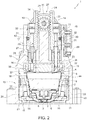
- the frame 10 comprises an upper portion 13, which supports a water injection unit 14, and a lower portion 15, which defines a seat 16 suitable to be removably engaged by the capsule holder 11 to support it in a brewing position under the injection unit 14.
- the needles 26 and 27 are kinematically connected to the actuator device 25 by means of a transmission 28 configured so as to make only one of the two needles 26 and 27 operational, in each delivery cycle, by moving said needle from the respective rest position to the respective operating position.
- the transmission 28 comprises two sliding blocks 31, each of which carries a respective needle 26, 27 in a rigidly coupled manner and is defined by a tubular generally cylindrical body slidingly mounted in a respective guide channel 32 obtained in the upper portion 13 of the frame 10 and open towards the seat 16.
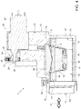
- each needle 26, 27 is axially aligned with a respective tubular appendix 36 of the cup-shaped gasket 23, said appendix extending downwards, from a bottom wall of the cup-shaped gasket 23, up to, and preferably slightly beyond, the annular end lip of said cup-shaped gasket 23.
- Each tubular appendix 36 is suitable to be slidingly engaged by the respective needle 26, 27 when the latter moves to the extracted operating position, and is shaped and dimensioned to fluid-tightly couple with the external surface of the part of needle that axially engages it.
- tubular appendages 36 have respective ends 37 which, when the capsule 2 is fluid-tightly coupled to the cup-shaped gasket 23 ( Figure 4 ), are pressed against the cover 4 and define respective annular seals suitable to prevent any water or beverage that has come out of the hole made by the "operational" needle and on to the cover 4 from entering the tubular appendages 36 and possibly reaching the channels 32.
- the cup-shaped gasket 23 internally houses an abutment element 38 rigidly connected to the frame 10 ( Figure 3 ) and bounded at the bottom by a surface that is rounded towards the bottom, which, when the capsule 2 is pressed against the cup-shaped gasket 23, engages the central portion of the cover 4 and pushes it inwardly into the capsule 2 to such an extent as to stretch said cover 4.
- each end 37 is inclined with respect to the longitudinal axis of the respective tubular appendage 36 at an angle such as to complement the curvature of the cover 4 in the connection area and adhere to the cover 4 in an effective manner.
- Figure 2 illustrates the rest position of the needle 26, which is the needle with the larger inside diameter capable of delivering water at a higher flow rate than the needle 27, and the rest position of the needle 27, which is the needle with the smaller inside diameter and delivers a lower flow rate.
- the needles 26 and 27 may be arranged, according to their length, completely inside the respective channels 32 (as is the case of the needle 27 in the example that is illustrated) or protrude from the respective channel 32 and engage a first section of the respective tubular appendage 36 (as is the case of the needle 26 in the example that is illustrated), but without extending, in any case, beyond the end 37 of said tubular appendage 36.
- Figure 5 illustrates the configuration of the needle injection device 24 when the needle 26 is in the extracted operating position and, consequently, the needle 27 is in its retracted waiting position.
- needles like the needle 26, which supply a high flow rate and at low speed are used for capsules 2 designed to produce beverages that have to be extracted at low pressure, for example infusions or Americano-type coffee; such capsules do not normally have the aforesaid micro-perforated sheet 9.
- needles of this type are normally made to penetrate the capsule 2 relatively deeply so as to inject water directly into the dose of material to be brewed.
- the needle 26 comprises a hollow cylindrical stem, a solid tip cut obliquely, and a water outlet on the side facing the centre of the capsule 2 in order to facilitate the circulation of the water through the material to be brewed.
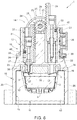
- Figure 6 illustrates the configuration of the needle injection device 24 when the needle 27 is in the extracted operating position and, consequently, the needle 26 is in the retracted waiting position.
- needles like the needle 27, which supply a low flow rate and at high speed, are used for capsules 2 designed for producing beverages that have to be extracted at high pressure, for example espresso coffee; such capsules are normally provided with the aforesaid micro-perforated sheet 9 which has the function of distributing the water and ensuring that it penetrates the material in a uniform manner.
- the needle 27 comprises a hollow cylindrical stem with a thin tip portion and an axial opening through which the water flows out.
- the time for which the motor 29 is driven and, thus, the length of the displacement of the "operational" needle 26 or 27 from the rest position to the extracted operating position, is controlled by the electronic control unit (not illustrated) on the basis of signals sent to said electronic unit by sensor means designed to detect the axial position of the sliding blocks 31 along the respective guide channels 32.
- said sensor means consist, for example, of a Hall effect sensor 39 (of the conventional type) mounted on the upper portion 13 of the frame 10 and coupled to magnets 40 mounted on the sliding blocks 31.
- the transmission 28 could be different from that illustrated, for example it could consist of a mechanical linkage transmission or a hydraulic transmission.
- the transmission 28 could be configured to move, each time, only the needle selected to perforate the capsule, leaving the other needle stationary in the respective rest position.
- the displacements of the needles 26 and 27 could be controlled on the basis of sensors other than the Hall effect sensor described above, for example by using an encoder coupled to the shaft 30 of the electric motor 29 or a hydraulic system or any other system suitable for the purpose.
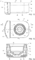
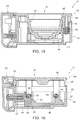
- the capsule holder 11 is designed as a drawer able to slide in the direction 17 of insertion/extraction between an extracted loading position, in which a capsule 2 can be loaded into/removed from the cavity 12, and a brewing position, in which the capsule holder 11 is inserted into the seat 16 in the frame 10 and the cavity 12, with the capsule 2 that has been inserted, is arranged underneath and in a position coaxial to the cup-shaped gasket 23.
- the capsule holder 11 is also configured to move the capsule 2 from and towards a fluid-tight coupling position with said cup-shaped gasket 23.
- the transmission device 55 is defined by a cam mechanism housed inside the lower portion 43 and comprising two cams 56, each of which is rigidly connected to a corresponding elongated element 54, at an axial end of the latter opposite to the end to which the handle 53 is connected, and has, along an upper profile thereof, two inclined planes 57 and two horizontal planes 58, each of which is adjacent to the top of a respective inclined plane 57.
- the transmission device 55 further comprises follower means defined, for each cam 56, by a pair of pins 59 rigidly coupled to the upper portion 44 and each coupled to a respective inclined plane 57. The constant contact between the pins 59 and the respective inclined planes 57 is guaranteed by the springs 52 that normally hold the upper portion 44 pushed downwards and towards the lower portion 43.
- the angle of the inclined planes 57 is such that when the handle 53 is moved from the spaced position to the close position, so that the cams 56 slide forward, the pins 59 follow the respective inclined planes 57 upwards from the bottom, thus raising the upper portion 44.
- the pins 59 engage the respective horizontal planes 58 to make the raised position of the upper portion 44 stable.
- the horizontal planes 58 have a slight concavity designed to be engaged by the pins 59 in order to prevent, in use, any stress unintentionally applied to the main body 41, for instance vibrations, from undermining the stability of the raised position of the upper portion 44.
- the capsule 2 comes into contact with the cup-shaped gasket 23 and is pushed into the cavity 12 with the subsequent deformation and perforation of the sealing film 7 by the tip 8.
- the transmission device 55 could have a different architecture from that of the example illustrated in the accompanying figures, and any type of mechanism capable of converting the horizontal displacement of the handle 53 into a vertical displacement of the upper portion 44 of the capsule holder 11 could be used.
Landscapes
- Engineering & Computer Science (AREA)
- Food Science & Technology (AREA)
- Mechanical Engineering (AREA)
- Apparatus For Making Beverages (AREA)
Claims (8)
- Appareil d'infusion de boissons (1) pour préparer une boisson à partir d'une capsule à usage unique (2) contenant une dose de matière infusible ou soluble ; l'appareil d'infusion de boissons (1) comprend un support de capsule (11) avec un siège de capsule (12) pour recevoir une capsule (2) dans une position d'infusion, et un appareil d'alimentation en fluide d'infusion (14) pour fournir un fluide d'infusion dans une capsule (2) dans la position d'infusion ; le support de capsule (11) est conçu comme un tiroir et est monté pour coulisser dans une direction d'insertion / d'extraction (17) afin de permettre à une capsule (2) d'être reçue et déplacée vers la position d'infusion, dans lequel la capsule (2) fait face à une sortie (23) de l'appareil d'alimentation en fluide d'infusion (14) ; le support de capsule (11) comprend un corps principal (41) pour supporter la capsule (2) et a une partie inférieure (43) et une partie supérieure (44) dotée du siège de capsule (12) et montée de façon coulissante sur la partie inférieure (43) pour se déplacer, par rapport à celle-ci, vers et depuis une position relevée, caractérisé en ce que dans la position relevée, la capsule (2) est couplée, en étant étanche aux fluides, à la sortie de l'appareil d'alimentation en fluide d'infusion (14).
- Appareil d'infusion de boissons (1) selon la revendication 1, comprenant en outre un siège (16) adéquat pour être engagé de façon coulissante par le support de capsule (11) pendant l'insertion / l'extraction du support de capsule (11) ; le siège (16) ayant un élément d'arrêt (47) pour limiter l'insertion du support de capsule (11) dans le siège (16) ; les parties inférieure et supérieure (43, 44) sont couplées de façon coulissante l'une à l'autre pour entraîner, pendant l'insertion du support de capsule (11), la partie supérieure (44) à rester fixe par rapport à la partie inférieure (43), et lorsque la partie inférieure (43) atteint l'élément d'arrêt (47), la partie supérieure (44) à coulisser par rapport à la partie inférieure (43) jusqu'à ce que la position relevée soit atteinte.
- Appareil d'infusion de boissons (1) selon la revendication 2, dans lequel le support de capsule (11) comprend des moyens de retenue et de retour (52) entre les parties inférieure et supérieure (43, 44) pour entraîner les parties inférieure et supérieure (43, 44) à se déplacer ensemble pendant l'insertion du support de capsule (11), et pour entraîner la partie supérieure (44) à glisser par rapport à la partie inférieure (43) lorsque la partie inférieure (43) atteint l'élément d'arrêt (47).
- Appareil d'infusion de boissons (1) selon la revendication 2 ou 3, comprenant une poignée (53) couplée à la partie inférieure (43) pour permettre au support de capsule (11) d'être actionné manuellement ; dans lequel la partie supérieure (44) est montée pour coulisser par rapport à la partie inférieure (43) dans une direction perpendiculaire à une direction d'insertion / d'extraction (17) en réponse à un mouvement de la poignée (53) par rapport à la partie inférieure (43) dans la direction d'insertion / d'extraction (17) lorsque la partie inférieure (43) atteint l'élément d'arrêt (47).
- Appareil d'infusion de boissons (1) selon la revendication 3, dans lequel les moyens de retenue et de retour (52) sont des moyens élastiques.
- Appareil d'infusion de boissons (1) selon la revendication 4, dans lequel le support de capsule (11) comprend une transmission (55) pour transformer un glissement de la poignée (53) par rapport à la partie inférieure (43) dans la direction d'insertion / d'extraction (17) en un glissement de la partie supérieure (44) par rapport à la partie inférieure (43) dans une direction perpendiculaire à la direction d'insertion / d'extraction (17) ; la transmission (55) comprend une came (56) couplée de façon rigide à la poignée (53), et un mentonnet (59) couplé de façon rigide à la partie supérieure (44).
- Appareil d'infusion de boissons (1) selon l'une quelconque des revendications précédentes, dans lequel la sortie (23) de l'appareil d'alimentation en fluide d'infusion (14) comprend un joint d'étanchéité (23), et l'appareil d'alimentation en fluide d'infusion (14) comprend deux aiguilles creuses (26, 27) déplaçables de manière sélective à travers le joint d'étanchéité (23) pour perforer la capsule (2).
- Appareil d'infusion de boissons (1) selon la revendication 4, comprenant en outre un détecteur de position (60) pour détecter lorsque le support de capsule (11) atteint l'élément d'arrêt (47).
Applications Claiming Priority (2)
| Application Number | Priority Date | Filing Date | Title |
|---|---|---|---|
| IT102016000130874A IT201600130874A1 (it) | 2016-12-23 | 2016-12-23 | Porta-capsula per un gruppo infusore per la preparazione di bevande a partire da capsule monouso |
| PCT/IB2017/058367 WO2018116279A1 (fr) | 2016-12-23 | 2017-12-22 | Porte-capsule d'un appareil d'infusion de préparation d'une boisson à partir d'une capsule à usage unique |
Publications (2)
| Publication Number | Publication Date |
|---|---|
| EP3558074A1 EP3558074A1 (fr) | 2019-10-30 |
| EP3558074B1 true EP3558074B1 (fr) | 2020-09-16 |
Family
ID=58670221
Family Applications (1)
| Application Number | Title | Priority Date | Filing Date |
|---|---|---|---|
| EP17832568.4A Active EP3558074B1 (fr) | 2016-12-23 | 2017-12-22 | Porte-capsule d'un appareil d'infusion de préparation d'une boisson à partir d'une capsule à usage unique |
Country Status (3)
| Country | Link |
|---|---|
| EP (1) | EP3558074B1 (fr) |
| IT (1) | IT201600130874A1 (fr) |
| WO (1) | WO2018116279A1 (fr) |
Families Citing this family (6)
| Publication number | Priority date | Publication date | Assignee | Title |
|---|---|---|---|---|
| CN109381022B (zh) * | 2018-11-30 | 2024-08-13 | 深圳市朗科智能电气股份有限公司 | 自动萃取胶囊咖啡机 |
| IT201900005462A1 (it) | 2019-04-09 | 2020-10-09 | Gruppo Gimoka S R L | Gruppo infusore per la preparazione di bevande a partire da capsule monouso |
| EP4147611A1 (fr) * | 2021-09-10 | 2023-03-15 | Delica AG | Machine de préparation de boissons, ainsi que procédé et système de préparation de boissons |
| EP4147610A1 (fr) * | 2021-09-10 | 2023-03-15 | Delica AG | Moitié de chambre de brassage, unité de brassage, machine de préparation de boissons, ainsi que procédé d'éjection d'une capsule et système de préparation de boissons |
| EP4147612A1 (fr) * | 2021-09-10 | 2023-03-15 | Delica AG | Unité de brassage, machine de préparation de boissons, ainsi que système de préparation de boissons |
| CN115708642B (zh) * | 2022-11-15 | 2025-07-08 | 深圳市西啡科技有限公司 | 一种萃取装置及饮料机 |
Family Cites Families (3)
| Publication number | Priority date | Publication date | Assignee | Title |
|---|---|---|---|---|
| ATE270516T1 (de) * | 2000-11-07 | 2004-07-15 | Smile Coffee S R L | Getränkeabgabevorrichtung |
| DE202004020913U1 (de) * | 2004-01-30 | 2006-04-13 | BSH Bosch und Siemens Hausgeräte GmbH | Kaffeemaschine mit einer Schublade zum Zuführen eines Kaffeepads |
| ITTO20090252A1 (it) * | 2009-04-01 | 2010-10-02 | Sgl Italia S R L Con Unico Socio | Gruppo percolatore per la produzione di una bevanda |
-
2016
- 2016-12-23 IT IT102016000130874A patent/IT201600130874A1/it unknown
-
2017
- 2017-12-22 WO PCT/IB2017/058367 patent/WO2018116279A1/fr not_active Ceased
- 2017-12-22 EP EP17832568.4A patent/EP3558074B1/fr active Active
Also Published As
| Publication number | Publication date |
|---|---|
| WO2018116279A1 (fr) | 2018-06-28 |
| EP3558074A1 (fr) | 2019-10-30 |
| IT201600130874A1 (it) | 2018-06-23 |
Similar Documents
| Publication | Publication Date | Title |
|---|---|---|
| EP3558078B1 (fr) | Appareil d'infusion pour préparer une boisson à partir d'une capsule à usage unique | |
| WO2018116279A1 (fr) | Porte-capsule d'un appareil d'infusion de préparation d'une boisson à partir d'une capsule à usage unique | |
| EP1900653B1 (fr) | Capsule scellée pour préparer une boisson | |
| US9186018B2 (en) | Dispensing assembly for machines for the preparation of beverages using capsules | |
| EP2033551B1 (fr) | Module de perforation de capsules | |
| CA2800862C (fr) | Dispositif d'infusion destine a la lixiviation d'une dosette, procede de fonctionnement d'un dispositif d'infusion et utilisation d'un dispositif d'infusion | |
| JP6223339B2 (ja) | カートリッジ位置合わせシステム | |
| JP6080849B2 (ja) | 抽出システムのカートリッジチャンバ | |
| US9119504B2 (en) | Delivery assembly for machines for preparing liquid products via cartridges | |
| EP2747608B1 (fr) | Perceur de cartouche longue durée | |
| EP1453405B1 (fr) | Procede et dispositif de preparation de boissons infusees | |
| EP2218370A2 (fr) | Unité de préparation de boisson | |
| AU2008212121A1 (en) | Infusion device to prepare beverages from single-serving capsules with capsule centering device | |
| CN103764001A (zh) | 料盒移除系统 | |
| CN107223031A (zh) | 用于用来分配冲泡形式的饮料的机器的冲泡组 | |
| CN118145186A (zh) | 茶胶囊及茶胶囊耐压冲泡系统 | |
| WO2015162468A1 (fr) | Appareil et procédé de fabrication de boisson à l'aide d'une substance alimentaire en poudre contenue dans une capsule | |
| HK1240476A1 (en) | Infusion group for machines for the dispensing of beverages in the form of infusion | |
| HK1127984B (en) | Capsule piercing module | |
| HK1134764B (en) | Infusion device to prepare beverages from single-serving capsules | |
| HK1134764A1 (en) | Infusion device to prepare beverages from single-serving capsules |
Legal Events
| Date | Code | Title | Description |
|---|---|---|---|
| STAA | Information on the status of an ep patent application or granted ep patent |
Free format text: STATUS: UNKNOWN |
|
| STAA | Information on the status of an ep patent application or granted ep patent |
Free format text: STATUS: THE INTERNATIONAL PUBLICATION HAS BEEN MADE |
|
| PUAI | Public reference made under article 153(3) epc to a published international application that has entered the european phase |
Free format text: ORIGINAL CODE: 0009012 |
|
| STAA | Information on the status of an ep patent application or granted ep patent |
Free format text: STATUS: REQUEST FOR EXAMINATION WAS MADE |
|
| 17P | Request for examination filed |
Effective date: 20190610 |
|
| AK | Designated contracting states |
Kind code of ref document: A1 Designated state(s): AL AT BE BG CH CY CZ DE DK EE ES FI FR GB GR HR HU IE IS IT LI LT LU LV MC MK MT NL NO PL PT RO RS SE SI SK SM TR |
|
| AX | Request for extension of the european patent |
Extension state: BA ME |
|
| DAV | Request for validation of the european patent (deleted) | ||
| DAX | Request for extension of the european patent (deleted) | ||
| GRAP | Despatch of communication of intention to grant a patent |
Free format text: ORIGINAL CODE: EPIDOSNIGR1 |
|
| STAA | Information on the status of an ep patent application or granted ep patent |
Free format text: STATUS: GRANT OF PATENT IS INTENDED |
|
| INTG | Intention to grant announced |
Effective date: 20200408 |
|
| GRAS | Grant fee paid |
Free format text: ORIGINAL CODE: EPIDOSNIGR3 |
|
| GRAA | (expected) grant |
Free format text: ORIGINAL CODE: 0009210 |
|
| STAA | Information on the status of an ep patent application or granted ep patent |
Free format text: STATUS: THE PATENT HAS BEEN GRANTED |
|
| AK | Designated contracting states |
Kind code of ref document: B1 Designated state(s): AL AT BE BG CH CY CZ DE DK EE ES FI FR GB GR HR HU IE IS IT LI LT LU LV MC MK MT NL NO PL PT RO RS SE SI SK SM TR |
|
| REG | Reference to a national code |
Ref country code: GB Ref legal event code: FG4D |
|
| REG | Reference to a national code |
Ref country code: CH Ref legal event code: EP |
|
| REG | Reference to a national code |
Ref country code: DE Ref legal event code: R096 Ref document number: 602017023909 Country of ref document: DE |
|
| REG | Reference to a national code |
Ref country code: IE Ref legal event code: FG4D |
|
| REG | Reference to a national code |
Ref country code: AT Ref legal event code: REF Ref document number: 1313354 Country of ref document: AT Kind code of ref document: T Effective date: 20201015 |
|
| PG25 | Lapsed in a contracting state [announced via postgrant information from national office to epo] |
Ref country code: HR Free format text: LAPSE BECAUSE OF FAILURE TO SUBMIT A TRANSLATION OF THE DESCRIPTION OR TO PAY THE FEE WITHIN THE PRESCRIBED TIME-LIMIT Effective date: 20200916 Ref country code: NO Free format text: LAPSE BECAUSE OF FAILURE TO SUBMIT A TRANSLATION OF THE DESCRIPTION OR TO PAY THE FEE WITHIN THE PRESCRIBED TIME-LIMIT Effective date: 20201216 Ref country code: GR Free format text: LAPSE BECAUSE OF FAILURE TO SUBMIT A TRANSLATION OF THE DESCRIPTION OR TO PAY THE FEE WITHIN THE PRESCRIBED TIME-LIMIT Effective date: 20201217 Ref country code: SE Free format text: LAPSE BECAUSE OF FAILURE TO SUBMIT A TRANSLATION OF THE DESCRIPTION OR TO PAY THE FEE WITHIN THE PRESCRIBED TIME-LIMIT Effective date: 20200916 Ref country code: FI Free format text: LAPSE BECAUSE OF FAILURE TO SUBMIT A TRANSLATION OF THE DESCRIPTION OR TO PAY THE FEE WITHIN THE PRESCRIBED TIME-LIMIT Effective date: 20200916 Ref country code: BG Free format text: LAPSE BECAUSE OF FAILURE TO SUBMIT A TRANSLATION OF THE DESCRIPTION OR TO PAY THE FEE WITHIN THE PRESCRIBED TIME-LIMIT Effective date: 20201216 |
|
| REG | Reference to a national code |
Ref country code: AT Ref legal event code: MK05 Ref document number: 1313354 Country of ref document: AT Kind code of ref document: T Effective date: 20200916 |
|
| REG | Reference to a national code |
Ref country code: NL Ref legal event code: MP Effective date: 20200916 |
|
| PG25 | Lapsed in a contracting state [announced via postgrant information from national office to epo] |
Ref country code: LV Free format text: LAPSE BECAUSE OF FAILURE TO SUBMIT A TRANSLATION OF THE DESCRIPTION OR TO PAY THE FEE WITHIN THE PRESCRIBED TIME-LIMIT Effective date: 20200916 Ref country code: RS Free format text: LAPSE BECAUSE OF FAILURE TO SUBMIT A TRANSLATION OF THE DESCRIPTION OR TO PAY THE FEE WITHIN THE PRESCRIBED TIME-LIMIT Effective date: 20200916 |
|
| REG | Reference to a national code |
Ref country code: LT Ref legal event code: MG4D |
|
| PG25 | Lapsed in a contracting state [announced via postgrant information from national office to epo] |
Ref country code: EE Free format text: LAPSE BECAUSE OF FAILURE TO SUBMIT A TRANSLATION OF THE DESCRIPTION OR TO PAY THE FEE WITHIN THE PRESCRIBED TIME-LIMIT Effective date: 20200916 Ref country code: RO Free format text: LAPSE BECAUSE OF FAILURE TO SUBMIT A TRANSLATION OF THE DESCRIPTION OR TO PAY THE FEE WITHIN THE PRESCRIBED TIME-LIMIT Effective date: 20200916 Ref country code: PT Free format text: LAPSE BECAUSE OF FAILURE TO SUBMIT A TRANSLATION OF THE DESCRIPTION OR TO PAY THE FEE WITHIN THE PRESCRIBED TIME-LIMIT Effective date: 20210118 Ref country code: CZ Free format text: LAPSE BECAUSE OF FAILURE TO SUBMIT A TRANSLATION OF THE DESCRIPTION OR TO PAY THE FEE WITHIN THE PRESCRIBED TIME-LIMIT Effective date: 20200916 Ref country code: LT Free format text: LAPSE BECAUSE OF FAILURE TO SUBMIT A TRANSLATION OF THE DESCRIPTION OR TO PAY THE FEE WITHIN THE PRESCRIBED TIME-LIMIT Effective date: 20200916 Ref country code: SM Free format text: LAPSE BECAUSE OF FAILURE TO SUBMIT A TRANSLATION OF THE DESCRIPTION OR TO PAY THE FEE WITHIN THE PRESCRIBED TIME-LIMIT Effective date: 20200916 |
|
| RAP4 | Party data changed (patent owner data changed or rights of a patent transferred) |
Owner name: GRUPPO GIMOKA S.R.L. |
|
| PG25 | Lapsed in a contracting state [announced via postgrant information from national office to epo] |
Ref country code: IS Free format text: LAPSE BECAUSE OF FAILURE TO SUBMIT A TRANSLATION OF THE DESCRIPTION OR TO PAY THE FEE WITHIN THE PRESCRIBED TIME-LIMIT Effective date: 20210116 Ref country code: PL Free format text: LAPSE BECAUSE OF FAILURE TO SUBMIT A TRANSLATION OF THE DESCRIPTION OR TO PAY THE FEE WITHIN THE PRESCRIBED TIME-LIMIT Effective date: 20200916 Ref country code: AL Free format text: LAPSE BECAUSE OF FAILURE TO SUBMIT A TRANSLATION OF THE DESCRIPTION OR TO PAY THE FEE WITHIN THE PRESCRIBED TIME-LIMIT Effective date: 20200916 Ref country code: AT Free format text: LAPSE BECAUSE OF FAILURE TO SUBMIT A TRANSLATION OF THE DESCRIPTION OR TO PAY THE FEE WITHIN THE PRESCRIBED TIME-LIMIT Effective date: 20200916 Ref country code: ES Free format text: LAPSE BECAUSE OF FAILURE TO SUBMIT A TRANSLATION OF THE DESCRIPTION OR TO PAY THE FEE WITHIN THE PRESCRIBED TIME-LIMIT Effective date: 20200916 |
|
| REG | Reference to a national code |
Ref country code: DE Ref legal event code: R097 Ref document number: 602017023909 Country of ref document: DE |
|
| PG25 | Lapsed in a contracting state [announced via postgrant information from national office to epo] |
Ref country code: SK Free format text: LAPSE BECAUSE OF FAILURE TO SUBMIT A TRANSLATION OF THE DESCRIPTION OR TO PAY THE FEE WITHIN THE PRESCRIBED TIME-LIMIT Effective date: 20200916 |
|
| PLBE | No opposition filed within time limit |
Free format text: ORIGINAL CODE: 0009261 |
|
| STAA | Information on the status of an ep patent application or granted ep patent |
Free format text: STATUS: NO OPPOSITION FILED WITHIN TIME LIMIT |
|
| 26N | No opposition filed |
Effective date: 20210617 |
|
| PG25 | Lapsed in a contracting state [announced via postgrant information from national office to epo] |
Ref country code: MC Free format text: LAPSE BECAUSE OF FAILURE TO SUBMIT A TRANSLATION OF THE DESCRIPTION OR TO PAY THE FEE WITHIN THE PRESCRIBED TIME-LIMIT Effective date: 20200916 Ref country code: DK Free format text: LAPSE BECAUSE OF FAILURE TO SUBMIT A TRANSLATION OF THE DESCRIPTION OR TO PAY THE FEE WITHIN THE PRESCRIBED TIME-LIMIT Effective date: 20200916 Ref country code: SI Free format text: LAPSE BECAUSE OF FAILURE TO SUBMIT A TRANSLATION OF THE DESCRIPTION OR TO PAY THE FEE WITHIN THE PRESCRIBED TIME-LIMIT Effective date: 20200916 |
|
| PG25 | Lapsed in a contracting state [announced via postgrant information from national office to epo] |
Ref country code: LU Free format text: LAPSE BECAUSE OF NON-PAYMENT OF DUE FEES Effective date: 20201222 Ref country code: IE Free format text: LAPSE BECAUSE OF NON-PAYMENT OF DUE FEES Effective date: 20201222 |
|
| PG25 | Lapsed in a contracting state [announced via postgrant information from national office to epo] |
Ref country code: TR Free format text: LAPSE BECAUSE OF FAILURE TO SUBMIT A TRANSLATION OF THE DESCRIPTION OR TO PAY THE FEE WITHIN THE PRESCRIBED TIME-LIMIT Effective date: 20200916 Ref country code: MT Free format text: LAPSE BECAUSE OF FAILURE TO SUBMIT A TRANSLATION OF THE DESCRIPTION OR TO PAY THE FEE WITHIN THE PRESCRIBED TIME-LIMIT Effective date: 20200916 Ref country code: CY Free format text: LAPSE BECAUSE OF FAILURE TO SUBMIT A TRANSLATION OF THE DESCRIPTION OR TO PAY THE FEE WITHIN THE PRESCRIBED TIME-LIMIT Effective date: 20200916 |
|
| PG25 | Lapsed in a contracting state [announced via postgrant information from national office to epo] |
Ref country code: MK Free format text: LAPSE BECAUSE OF FAILURE TO SUBMIT A TRANSLATION OF THE DESCRIPTION OR TO PAY THE FEE WITHIN THE PRESCRIBED TIME-LIMIT Effective date: 20200916 |
|
| PG25 | Lapsed in a contracting state [announced via postgrant information from national office to epo] |
Ref country code: NL Free format text: LAPSE BECAUSE OF NON-PAYMENT OF DUE FEES Effective date: 20200923 |
|
| PGFP | Annual fee paid to national office [announced via postgrant information from national office to epo] |
Ref country code: BE Payment date: 20241224 Year of fee payment: 8 |
|
| PGFP | Annual fee paid to national office [announced via postgrant information from national office to epo] |
Ref country code: GB Payment date: 20241217 Year of fee payment: 8 |
|
| PGFP | Annual fee paid to national office [announced via postgrant information from national office to epo] |
Ref country code: FR Payment date: 20241227 Year of fee payment: 8 |
|
| PGFP | Annual fee paid to national office [announced via postgrant information from national office to epo] |
Ref country code: IT Payment date: 20241122 Year of fee payment: 8 |
|
| PGFP | Annual fee paid to national office [announced via postgrant information from national office to epo] |
Ref country code: DE Payment date: 20241227 Year of fee payment: 8 |
|
| PGFP | Annual fee paid to national office [announced via postgrant information from national office to epo] |
Ref country code: CH Payment date: 20250101 Year of fee payment: 8 |