EP3558047B1 - Shoe comprising a midsole - Google Patents
Shoe comprising a midsole Download PDFInfo
- Publication number
- EP3558047B1 EP3558047B1 EP17835498.1A EP17835498A EP3558047B1 EP 3558047 B1 EP3558047 B1 EP 3558047B1 EP 17835498 A EP17835498 A EP 17835498A EP 3558047 B1 EP3558047 B1 EP 3558047B1
- Authority
- EP
- European Patent Office
- Prior art keywords
- shoe
- projections
- sole
- midsole
- projection
- Prior art date
- Legal status (The legal status is an assumption and is not a legal conclusion. Google has not performed a legal analysis and makes no representation as to the accuracy of the status listed.)
- Not-in-force
Links
Images


Classifications
-
- A—HUMAN NECESSITIES
- A43—FOOTWEAR
- A43B—CHARACTERISTIC FEATURES OF FOOTWEAR; PARTS OF FOOTWEAR
- A43B23/00—Uppers; Boot legs; Stiffeners; Other single parts of footwear
- A43B23/02—Uppers; Boot legs
- A43B23/0205—Uppers; Boot legs characterised by the material
- A43B23/021—Leather
-
- A—HUMAN NECESSITIES
- A43—FOOTWEAR
- A43B—CHARACTERISTIC FEATURES OF FOOTWEAR; PARTS OF FOOTWEAR
- A43B13/00—Soles; Sole-and-heel integral units
- A43B13/14—Soles; Sole-and-heel integral units characterised by the constructive form
- A43B13/18—Resilient soles
- A43B13/181—Resiliency achieved by the structure of the sole
- A43B13/186—Differential cushioning region, e.g. cushioning located under the ball of the foot
-
- A—HUMAN NECESSITIES
- A43—FOOTWEAR
- A43B—CHARACTERISTIC FEATURES OF FOOTWEAR; PARTS OF FOOTWEAR
- A43B13/00—Soles; Sole-and-heel integral units
- A43B13/02—Soles; Sole-and-heel integral units characterised by the material
- A43B13/04—Plastics, rubber or vulcanised fibre
-
- A—HUMAN NECESSITIES
- A43—FOOTWEAR
- A43B—CHARACTERISTIC FEATURES OF FOOTWEAR; PARTS OF FOOTWEAR
- A43B13/00—Soles; Sole-and-heel integral units
- A43B13/02—Soles; Sole-and-heel integral units characterised by the material
- A43B13/12—Soles with several layers of different materials
- A43B13/125—Soles with several layers of different materials characterised by the midsole or middle layer
-
- A—HUMAN NECESSITIES
- A43—FOOTWEAR
- A43B—CHARACTERISTIC FEATURES OF FOOTWEAR; PARTS OF FOOTWEAR
- A43B13/00—Soles; Sole-and-heel integral units
- A43B13/14—Soles; Sole-and-heel integral units characterised by the constructive form
-
- A—HUMAN NECESSITIES
- A43—FOOTWEAR
- A43B—CHARACTERISTIC FEATURES OF FOOTWEAR; PARTS OF FOOTWEAR
- A43B13/00—Soles; Sole-and-heel integral units
- A43B13/14—Soles; Sole-and-heel integral units characterised by the constructive form
- A43B13/18—Resilient soles
- A43B13/181—Resiliency achieved by the structure of the sole
-
- A—HUMAN NECESSITIES
- A43—FOOTWEAR
- A43B—CHARACTERISTIC FEATURES OF FOOTWEAR; PARTS OF FOOTWEAR
- A43B13/00—Soles; Sole-and-heel integral units
- A43B13/14—Soles; Sole-and-heel integral units characterised by the constructive form
- A43B13/18—Resilient soles
- A43B13/20—Pneumatic soles filled with a compressible fluid, e.g. air, gas
- A43B13/206—Pneumatic soles filled with a compressible fluid, e.g. air, gas provided with tubes or pipes or tubular shaped cushioning members
-
- A—HUMAN NECESSITIES
- A43—FOOTWEAR
- A43B—CHARACTERISTIC FEATURES OF FOOTWEAR; PARTS OF FOOTWEAR
- A43B13/00—Soles; Sole-and-heel integral units
- A43B13/28—Soles; Sole-and-heel integral units characterised by their attachment, also attachment of combined soles and heels
- A43B13/36—Easily-exchangeable soles
-
- A—HUMAN NECESSITIES
- A43—FOOTWEAR
- A43B—CHARACTERISTIC FEATURES OF FOOTWEAR; PARTS OF FOOTWEAR
- A43B23/00—Uppers; Boot legs; Stiffeners; Other single parts of footwear
- A43B23/02—Uppers; Boot legs
-
- A—HUMAN NECESSITIES
- A43—FOOTWEAR
- A43B—CHARACTERISTIC FEATURES OF FOOTWEAR; PARTS OF FOOTWEAR
- A43B9/00—Footwear characterised by the assembling of the individual parts
Definitions
- the invention relates to a shoe comprising a sole and a midsole having a series of projections that can be housed in corresponding recesses made in the sole.
- US patent 7793428 describes a shoe comprising an upper and an upper plate made of a relatively rigid material, which plate is secured to the upper and in which a plurality of openings are made.
- the removable midsole comprises a plurality of projections that extend from a lower surface, with each projection extending through one of the openings in the upper plate.
- a plurality of hollow column-shaped structures are provided in the heel portion, inside which structures the above-mentioned projections are housed.
- the column-shaped structures may be made of a transparent material such that the projections housed therein are visible.
- the technical problem that forms the basis of the present invention is that of providing a shoe, the structure and function of which are designed to overcome one or more of the limiting factors set out above with reference to the cited prior art.
- the main object of the invention is to develop a shoe having an interchangeable midsole, in which it is possible to change the characteristics of the sole in the various regions of the sole, and which object simultaneously makes it possible to effectively couple the midsole to the sole.
- the sole according to the present invention makes it possible to use the projections provided on the midsole both to couple it to the sole and to change the characteristics of the shoe in the various regions of the sole.
- the midsole can be positioned both stably and accurately, thus ensuring that it is simple to replace.
- the invention also makes it possible to elastically recover the energy that is transferred to the shoe in the course of a walking movement.
- the present invention also makes it possible to facilitate the helical motion of the foot caused during the various phases of walking.
- the invention also makes it possible to use high-quality materials to produce the upper, it thus being possible to produce the sole of the shoe using modern technology, such as injection-moulding. In this way, the need to produce a high-quality shoe that is producible on an industrial scale can be met.
- the present invention makes it possible to provide a shoe that is particularly stable during oscillatory movements when walking.
- reference numeral 100 indicates a shoe as a whole, which is produced in accordance with the present invention.
- the shoe 100 extends longitudinally in a toe-to-heel direction indicated by the letter X in Fig. 2 .
- the shoe comprises an upper 1 and a sole 2, in which a forefoot region 11, a midfoot region 12 and a rearfoot region 13 are defined, which are adjacent to one another in the toe-to-heel direction X.
- a tread surface 20 is defined on the sole 2 and comes into contact with the ground when the shoe 100 is being used.
- a midsole 3 is also removably housed inside the shoe 100.
- the midsole 3 advantageously also functions as an anatomical footbed.
- the midsole is made of a material having a relatively high degree of flexibility, such as polyurethane (PU).
- PU polyurethane
- the midsole 3 preferably also comprises a cover that can absorb sweat and may have antibacterial characteristics.
- the midsole 3 can be inserted into the shoe 100 so as to be situated above the sole, thereby defining a surface on which the foot of the wearer rests.
- the midsole 3 comprises a contact surface 30 which, in contrast, faces the sole 2.
- the midsole 3 and the sole 2 can bear against one another either directly or by means of the interposition of additional layers.
- the upper 1 comprises a base surface 16 for this purpose, which is preferably formed by a layer made of leather or of another material, possibly a synthetic material, which is used to make the upper.
- the base surface has through-openings 17, 18, the function of which will be illustrated below.
- the through-openings 17, 18 are preferably in a central region of the forefoot and rearfoot regions such that the base surface extends along the entire contour of the upper 1 and into the midfoot region.
- the base surface 16 can be fixed along the contour, preferably the entire contour, of the upper 1, with the central part extending in the form of a bridge between opposing lateral sides thereof.
- the base surface 16 is sewn to the upper 1 along its contour.
- the features of the upper are similar to those obtained using classic Strobel workmanship.
- the shoe according to the present invention is also particularly suitable for producing classic and elegant models.
- the sole 1 comprises a plurality of recesses 26, 27, which are preferably made in the forefoot region 11 and the rearfoot region 13.
- the openings 17 and 18 in the base surface 16 advantageously allow access to the recesses 26 and 27, respectively.
- the midsole 3 in turn comprises a plurality of projections 31, 32, which are received in the recesses 26 and 27, respectively, in the sole 2 and which extend from a contact surface 30 of the midsole 3, against which the foot of the wearer rests.
- said projections can be substantially cylindrical or, even more preferably, truncated cone-shaped.
- the recesses 26 in the forefoot region are blind at a relative bottom surface 28.
- the recesses 27 in the rearfoot region are preferably also blind.
- the length d, which extends away from the contact surface 30, of at least the forefoot region is of such a size that one end 34 of the projections 31 is in contact with the bottom surface 28 of the recesses 26.
- the above-mentioned length d is preferably greater than the depth of the corresponding recess.
- the recess 26 is spaced apart from the projection 31 in a region that is adjacent to an inlet mouth thereof so as to define a gap in said region. In one embodiment, the gap is defined between the projection 31 and a lateral wall 22 of the corresponding recess 26.
- the gap preferably runs around the outer edge of the projection 31 in the region in which the projection 31 connects to the contact surface 30. More generally, the gaps are defined in the recess 26, at least in the toe-to-heel direction of the shoe 100.
- the projection 31 rests against the bottom surface 28 by its end 34, but is spaced apart from the recess 26 in which it is housed and preferably also from the sole portion 2 that surrounds the recess 26 itself at the opposite end.
- the contact surface 30, or more generally the midsole 3 is therefore spaced apart from the sole 2 in regions adjacent to the inlet mouth of the recesses 26. The above-mentioned configuration therefore allows the projection 31 to compress and consequently expand when the wearer exerts pressure on the midsole 3 in the course of a walking movement.
- the projections 31 can be compressed, as a result of the walking movement, at the point when the ends 34 are in contact with the bottom surface 28 as a result of the presence of the gap described above and/or as a result of a greater length of the projection 31 with respect to the depth of the recess, and/or as a result of the intrinsic characteristics of the material used to make the midsole 3.
- the projections 31 are preferably made of the same material as the midsole 3.
- the projections are made of a material having a Shore hardness of between 18 and 25.
- the ability of the projections 31 to compress is associated with the dimensions and the shape of the gap that remains defined. The greater the dimensions of the gap and provided that the gap runs around the projection in a uniform manner, the greater its ability to deform.
- This feature is particularly useful for facilitating the walking movement.
- the projections and the corresponding recesses are designed such that the gaps widen in a longitudinal extent direction of the projection extending away from said end 34.
- this makes it possible to facilitate the insertion of the projections into the recesses and, on the other hand, allows for progressive deformation when walking.
- the gap can also have characteristics on the side facing the toe of the shoe that differ from those on the side facing the heel.
- the lateral wall portion of the projection and/or of the corresponding recess that faces the toe is at a greater incline with respect to a vertical direction than the portion facing the heel.
- the end 34 of the projection 31 is substantially flat and is inclined with respect to a horizontal direction defined by the plane of contact between the sole 2 and the ground.
- the end is preferably inclined such that the portion of the end 34 that faces the toe of the shoe is closer to the ground than the portion facing the heel.
- This can advantageously increase the compressive effect in the course of the walking movement, thus further contributing to improving the features of the shoe.
- the present invention is also advantageous in that it makes it possible to change the behaviour of the midsole 3 between one zone of the sole and another.
- the characteristics of the gap determine the behaviour of the midsole in the course of the walking movement.
- a plurality of projections 31 can be provided in the forefoot region, which are preferably substantially uniformly distributed in this region.
- gaps of different sizes may be provided.
- the projections 31 comprise first projections 31a, illustrated in Fig. 8A , and second projections 31B, illustrated in Fig. 8B .
- the gap defined between the first projection 31a and the lateral wall 22 of the corresponding recess has a different size to the gap defined between the second projection 31b and the lateral wall 22 of the corresponding recess. It is clear that this feature can be achieved by varying the shape and/or dimensions of both the projections and the recesses.
- the shape and/or dimensions of the gap between the first projections 31a and the lateral walls allow/allows for a greater degree of deformation than the gap between the second projections 31b and the lateral walls.
- the maximum gap between the first projections 31a and the lateral walls can be approximately 0.5 mm, for example between 0.25 mm and 0.75 mm, while the maximum gap between the second projections 31b and the lateral walls can be approximately 1.5 mm, for example between 1 mm and 2 mm.
- the first and the second projections comprise respective graphic elements, for example the symbols "+” and "-”, which make it clear which characteristics belong to which projection.
- the second projections 31b are arranged in a longitudinally and/or transversally central portion of the forefoot region.
- the characteristics of the midsole 3 and, in particular, of the projections 31, are variable in a direction that is transverse to the toe-to-heel direction of the shoe 100.
- the midsole has a greater ability to compress in the forefoot region on the side facing the outer side 15 of the shoe, which region is shown in the figure by a dotted line running therearound.
- This feature can also be formed by changing the characteristics of the material, for example by using higher density polyurethane in the above-mentioned zone.
- This different length advantageously makes it possible to facilitate the helical motion of the foot when walking.
- the features described in relation to the projections 31 present in the forefoot region can also be adopted for the projections 32 in the rearfoot region.
- the rearfoot zone only comprises three projections 32, the length d of which can be varied individually in order to adapt the shoe to the different postures of the foot.
- the sole of the shoe according to the present invention can be formed in a simple manner using injection-moulding techniques.
- the recesses 26 can be formed as through-recesses and subsequently closed by a sheet 4 that is fixed to said sole 2.
- the bottom surface 28 is defined by the sheet 4 itself.
- the sheet 4 is made of a material having a higher hardness (shore) than the sole 2, for example thermoplastic polyurethane (TPU).
- TPU thermoplastic polyurethane
- Non-slip elements 25 are preferably fixed to the sheet 4.
- the sheet 4 is made of a transparent or semitransparent material such that it is also possible to observe the characteristics of the projections from the outside and to recognise the characteristics of the shoe without removing the midsole.
- the shoe 100 can be effectively adapted to the different types of feet and postures using one solution that has a high visual impact and is also usable in classic shoe models.
Landscapes
- Chemical & Material Sciences (AREA)
- Engineering & Computer Science (AREA)
- Materials Engineering (AREA)
- Life Sciences & Earth Sciences (AREA)
- Zoology (AREA)
- Footwear And Its Accessory, Manufacturing Method And Apparatuses (AREA)
Description
- The invention relates to a shoe comprising a sole and a midsole having a series of projections that can be housed in corresponding recesses made in the sole.
- Various solutions for inserting a midsole inside a shoe, in particular so that it is coupled to the sole, are known.
- For example,
US patent 7793428 describes a shoe comprising an upper and an upper plate made of a relatively rigid material, which plate is secured to the upper and in which a plurality of openings are made. The removable midsole comprises a plurality of projections that extend from a lower surface, with each projection extending through one of the openings in the upper plate. - A plurality of hollow column-shaped structures are provided in the heel portion, inside which structures the above-mentioned projections are housed.
- The column-shaped structures may be made of a transparent material such that the projections housed therein are visible.
- In this way, when the midsole is replaced with a different midsole having projections of different colours, the wearer is able to visibly see that the midsole has been replaced.
- However, the presence of the upper plate and of the column-shaped structures fixed thereto makes it difficult to produce a shoe in which the flexibility characteristics are changed in the various regions of the sole.
- Additional documents that describe similar solutions include patent applications
US 2016/324264 andWO 2016/115156 . - However, the need has arisen to produce a shoe in which the various regions of the sole can have a different degree of flexibility or, more generally, a different response in the course of a walking movement.
- The technical problem that forms the basis of the present invention is that of providing a shoe, the structure and function of which are designed to overcome one or more of the limiting factors set out above with reference to the cited prior art.
- Within the context of the above-mentioned problem, the main object of the invention is to develop a shoe having an interchangeable midsole, in which it is possible to change the characteristics of the sole in the various regions of the sole, and which object simultaneously makes it possible to effectively couple the midsole to the sole.
- This problem is solved and these objects are achieved by the present invention by means of a shoe formed according to claim 1.
- Preferred features of the invention are defined in the dependent claims.
- The sole according to the present invention makes it possible to use the projections provided on the midsole both to couple it to the sole and to change the characteristics of the shoe in the various regions of the sole. In addition, the midsole can be positioned both stably and accurately, thus ensuring that it is simple to replace.
- According to preferred aspects, the invention also makes it possible to elastically recover the energy that is transferred to the shoe in the course of a walking movement.
- According to additional aspects, the present invention also makes it possible to facilitate the helical motion of the foot caused during the various phases of walking.
- According to other aspects, the invention also makes it possible to use high-quality materials to produce the upper, it thus being possible to produce the sole of the shoe using modern technology, such as injection-moulding. In this way, the need to produce a high-quality shoe that is producible on an industrial scale can be met.
- According to even more aspects, the present invention makes it possible to provide a shoe that is particularly stable during oscillatory movements when walking.
- The features and advantages of the invention will become clearer from the detailed description of two embodiments thereof, which are illustrated by way of non-limiting example, and with reference to the accompanying drawings, in which:
-
Fig. 1 is a side view of a shoe according to the present invention; -
Fig. 2 is a view from below of the shoe inFig. 1 ; -
Fig. 3 is a lateral, partially exploded view of the shoe inFig. 1 ; -
Fig. 4 is a partial view from above of the shoe according to the present invention, from which a relative midsole has been removed; -
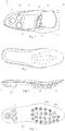
Fig. 5 to 7 are a view from above, a view from the side and a view from below, respectively, of the midsole of the shoe according to the present invention; -
Fig. 8 is a view from below of the midsole, in which first and second projections are identified; -
Fig. 8A and 8B are schematic lateral sectional views of the first and the second projections of the midsole, respectively, which are housed in corresponding recesses in the sole; -
Fig. 9 is a view from above that shows another aspect of the midsole according to the present invention; -
Fig. 9A is a schematic illustration showing the effect of the aspect illustrated inFig. 9 ; and -
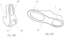
Fig. 10A and 10B are perspective views showing the upper of the shoe according to the present invention. - With reference to
Fig. 1 first of all,reference numeral 100 indicates a shoe as a whole, which is produced in accordance with the present invention. - The
shoe 100 extends longitudinally in a toe-to-heel direction indicated by the letter X inFig. 2 . - The shoe comprises an upper 1 and a sole 2, in which a forefoot region 11, a
midfoot region 12 and arearfoot region 13 are defined, which are adjacent to one another in the toe-to-heel direction X. - A
tread surface 20 is defined on the sole 2 and comes into contact with the ground when theshoe 100 is being used. - A
midsole 3 is also removably housed inside theshoe 100. - Although the characteristics of the midsole are specified in detail below, it should be noted that, according to one aspect of the present invention, the
midsole 3 advantageously also functions as an anatomical footbed. In this regard, the midsole is made of a material having a relatively high degree of flexibility, such as polyurethane (PU). Themidsole 3 preferably also comprises a cover that can absorb sweat and may have antibacterial characteristics. - The
midsole 3 can be inserted into theshoe 100 so as to be situated above the sole, thereby defining a surface on which the foot of the wearer rests. - On the opposite side, the
midsole 3 comprises acontact surface 30 which, in contrast, faces the sole 2. Themidsole 3 and the sole 2 can bear against one another either directly or by means of the interposition of additional layers. - According to a preferred embodiment shown in
Fig. 10A and 10B , the upper 1 comprises abase surface 16 for this purpose, which is preferably formed by a layer made of leather or of another material, possibly a synthetic material, which is used to make the upper. - As can be seen from
Fig. 10A and 10B , in one embodiment the base surface has through-openings openings - In this way, the
base surface 16 can be fixed along the contour, preferably the entire contour, of the upper 1, with the central part extending in the form of a bridge between opposing lateral sides thereof. - It should therefore be noted that this increases the stability of the structure of the upper, and therefore of the shoe as a whole, thus allowing the
midsole 3 to be housed as per the embodiments that will be described below. - In one embodiment, the
base surface 16 is sewn to the upper 1 along its contour. - In fact, the features of the upper are similar to those obtained using classic Strobel workmanship. In this way, the shoe according to the present invention is also particularly suitable for producing classic and elegant models.
- With reference now to
Fig. 4 , the sole 1 comprises a plurality ofrecesses rearfoot region 13. As can be seen in the figure, theopenings base surface 16 advantageously allow access to therecesses - With reference to
Fig. 6 , too, themidsole 3 in turn comprises a plurality ofprojections recesses contact surface 30 of themidsole 3, against which the foot of the wearer rests. - Therefore, corresponding projections and recesses are positively coupled, making it possible to accurately position the midsole inside the
shoe 100. - In order to facilitate the insertion of the projections, said projections can be substantially cylindrical or, even more preferably, truncated cone-shaped.
- As can be seen from
Fig. 8A and 8B in particular, therecesses 26 in the forefoot region are blind at arelative bottom surface 28. Therecesses 27 in the rearfoot region are preferably also blind. - As shown in the figures, the length d, which extends away from the
contact surface 30, of at least the forefoot region is of such a size that oneend 34 of theprojections 31 is in contact with thebottom surface 28 of therecesses 26. - The above-mentioned length d is preferably greater than the depth of the corresponding recess.
In one embodiment, therecess 26 is spaced apart from theprojection 31 in a region that is adjacent to an inlet mouth thereof so as to define a gap in said region. In one embodiment, the gap is defined between theprojection 31 and alateral wall 22 of thecorresponding recess 26. - The gap preferably runs around the outer edge of the
projection 31 in the region in which theprojection 31 connects to thecontact surface 30. More generally, the gaps are defined in therecess 26, at least in the toe-to-heel direction of theshoe 100. - In other words, the
projection 31 rests against thebottom surface 28 by itsend 34, but is spaced apart from therecess 26 in which it is housed and preferably also from thesole portion 2 that surrounds therecess 26 itself at the opposite end. Thecontact surface 30, or more generally themidsole 3, is therefore spaced apart from the sole 2 in regions adjacent to the inlet mouth of therecesses 26. The above-mentioned configuration therefore allows theprojection 31 to compress and consequently expand when the wearer exerts pressure on themidsole 3 in the course of a walking movement. - It should be noted that the
projections 31 can be compressed, as a result of the walking movement, at the point when the ends 34 are in contact with thebottom surface 28 as a result of the presence of the gap described above and/or as a result of a greater length of theprojection 31 with respect to the depth of the recess, and/or as a result of the intrinsic characteristics of the material used to make themidsole 3. In this regard, theprojections 31 are preferably made of the same material as themidsole 3. In one embodiment, the projections are made of a material having a Shore hardness of between 18 and 25. - However, the above-mentioned features are preferably combined.
- It should also be noted that the ability of the
projections 31 to compress is associated with the dimensions and the shape of the gap that remains defined. The greater the dimensions of the gap and provided that the gap runs around the projection in a uniform manner, the greater its ability to deform. - By using a sufficiently resilient material, it is possible to produce a cushioning effect that is linked to the compression of the projections when the foot rests against the ground, and elastic return of the material, with a consequent release of energy, when the foot is raised again.
- This feature is particularly useful for facilitating the walking movement.
- In one embodiment, the projections and the corresponding recesses are designed such that the gaps widen in a longitudinal extent direction of the projection extending away from said
end 34. On the one hand, this makes it possible to facilitate the insertion of the projections into the recesses and, on the other hand, allows for progressive deformation when walking. - In order to optimise the response of the projections during walking, the gap can also have characteristics on the side facing the toe of the shoe that differ from those on the side facing the heel.
- For this reason, the lateral wall portion of the projection and/or of the corresponding recess that faces the toe is at a greater incline with respect to a vertical direction than the portion facing the heel.
- In one embodiment, which may be combined with the embodiment described above, the
end 34 of theprojection 31 is substantially flat and is inclined with respect to a horizontal direction defined by the plane of contact between the sole 2 and the ground. The end is preferably inclined such that the portion of theend 34 that faces the toe of the shoe is closer to the ground than the portion facing the heel. - This can advantageously increase the compressive effect in the course of the walking movement, thus further contributing to improving the features of the shoe.
- However, the present invention is also advantageous in that it makes it possible to change the behaviour of the
midsole 3 between one zone of the sole and another. - In fact, as touched upon above, the characteristics of the gap determine the behaviour of the midsole in the course of the walking movement.
- By choosing a suitable number of projections and changing the characteristics of the coupling between the projection and the corresponding recess, it will therefore be possible to produce different behaviours depending on the region of the sole.
- In this regard, in one embodiment, a plurality of
projections 31 can be provided in the forefoot region, which are preferably substantially uniformly distributed in this region. - As illustrated schematically in
Fig. 8, 8A and 8B , in the shoe according to the present invention, gaps of different sizes may be provided. - For this purpose, in one embodiment, the
projections 31 comprisefirst projections 31a, illustrated inFig. 8A , and second projections 31B, illustrated inFig. 8B . - The gap defined between the
first projection 31a and thelateral wall 22 of the corresponding recess has a different size to the gap defined between thesecond projection 31b and thelateral wall 22 of the corresponding recess. It is clear that this feature can be achieved by varying the shape and/or dimensions of both the projections and the recesses. - As can be seen from
Fig. 8A and 8B , the shape and/or dimensions of the gap between thefirst projections 31a and the lateral walls allow/allows for a greater degree of deformation than the gap between thesecond projections 31b and the lateral walls. By way of example, the maximum gap between thefirst projections 31a and the lateral walls can be approximately 0.5 mm, for example between 0.25 mm and 0.75 mm, while the maximum gap between thesecond projections 31b and the lateral walls can be approximately 1.5 mm, for example between 1 mm and 2 mm. - According to a preferred embodiment, the first and the second projections comprise respective graphic elements, for example the symbols "+" and "-", which make it clear which characteristics belong to which projection.
- In one embodiment, the
second projections 31b are arranged in a longitudinally and/or transversally central portion of the forefoot region. - In this way, more support can advantageously be given to the foot in the central part of the forefoot region of the shoe. With reference now to
Fig. 9 and 9A , according to another aspect of the invention, the characteristics of themidsole 3 and, in particular, of theprojections 31, are variable in a direction that is transverse to the toe-to-heel direction of theshoe 100. As shown inFig. 9 and 9A , in one embodiment, the midsole has a greater ability to compress in the forefoot region on the side facing theouter side 15 of the shoe, which region is shown in the figure by a dotted line running therearound. - This feature can also be formed by changing the characteristics of the material, for example by using higher density polyurethane in the above-mentioned zone.
- This different length advantageously makes it possible to facilitate the helical motion of the foot when walking.
- It should be noted that the features described in relation to the
projections 31 present in the forefoot region can also be adopted for theprojections 32 in the rearfoot region. In the present embodiment, however, the rearfoot zone only comprises threeprojections 32, the length d of which can be varied individually in order to adapt the shoe to the different postures of the foot. - With reference now to
Fig. 2 ,8A and 8B once again, it will be noted that the sole of the shoe according to the present invention can be formed in a simple manner using injection-moulding techniques. - In order to facilitate the production of the sole, the
recesses 26 can be formed as through-recesses and subsequently closed by a sheet 4 that is fixed to said sole 2. - In this way, the
bottom surface 28 is defined by the sheet 4 itself. In one embodiment, the sheet 4 is made of a material having a higher hardness (shore) than the sole 2, for example thermoplastic polyurethane (TPU). This combination of materials advantageously makes it possible to compensate for the presence of the recesses, maintaining optimum flexibility of the sole. -
Non-slip elements 25 are preferably fixed to the sheet 4. In addition, according to a preferred embodiment, the sheet 4 is made of a transparent or semitransparent material such that it is also possible to observe the characteristics of the projections from the outside and to recognise the characteristics of the shoe without removing the midsole. - On account of the features of the invention, the
shoe 100 can be effectively adapted to the different types of feet and postures using one solution that has a high visual impact and is also usable in classic shoe models.
Claims (15)
- Shoe (100) comprising an upper (1), a sole (2) which defines a substantially flat tread surface (20) that makes contact with the ground, and a midsole (3) that can be removably accommodated inside said upper (1) and can be placed on top of said sole (2), said midsole (3) comprising a plurality of projections (31, 33) at least in a forefoot region, which are received inside corresponding recesses (26, 27) made in said sole (2), said recesses (26, 27) being blind at a relative bottom surface (28) such that said projections (31, 33) do not project from said tread surface (20), wherein one end (34) of said plurality of projections (31, 33) is in contact with said bottom surface (28) of said recesses (26, 27) at least in said forefoot region (21) such that said projections (31, 33) are subjected to compression by the foot of the wearer during a walking movement, wherein said projections (31) are accommodated inside said recesses (26) such that a gap remains defined between the projection (31) and a lateral wall (22) of the corresponding recess (26).
- Shoe (100) according to claim 1, wherein said gap has different characteristics on the side facing the toe of the shoe to those on the side facing the heel.
- Shoe (100) according to either claim 1 or claim 2, wherein the lateral wall portion of the projection and/or of the corresponding recess that faces the toe is at a greater incline with respect to a vertical direction than the portion that faces the heel.
- Shoe (100) according to any one of claims 1 to 3, wherein the end (34) of the projection (31) is substantially flat and is inclined with respect to a horizontal direction defined by a plane of contact between the sole (2) and the ground.
- Shoe (100) according to claim 4, wherein said end (34) is inclined such that the portion of the end (34) that faces the toe of the shoe is closer to the ground than the portion facing the heel.
- Shoe (100) according to any one of claims 1 to 5, wherein said projections (31) comprise first projections (31a) and second projections (31b), wherein the gap defined between a first projection (31a) and a lateral wall (22) of the corresponding recess has a different size to the gap defined between a second projection (31b) and a lateral wall (22) of the corresponding recess.
- Shoe according to claim 6, wherein the gap between the first projections (31a) and the lateral walls is no greater than between 0.25 mm and 0.75 mm, and the gap between the second projections (31b) and the lateral walls is no greater than between 1 mm and 2 mm.
- Shoe (100) according to any one of claims 1 to 7, wherein said gaps are defined in said recess (26) at least in the toe-to-heel direction of the shoe (100).
- Shoe (100) according to any one of claims 1 to 8, wherein said gaps widen in a longitudinal extent direction of the projection extending away from said end (34).
- Shoe (100) according to any one of the preceding claims, wherein said projections (31, 32) are cylindrical or truncated cone-shaped.
- Shoe (100) according to any one of the preceding claims, wherein said upper (1) comprises a base surface (16) having through-openings (17, 18), through which said projections (31, 32) pass.
- Shoe (100) according to claim 11, wherein said base surface (16) has a first through-opening (17) that occupies a central region of the forefoot region, and a second through-opening (18) that occupies a central region of the rearfoot region.
- Shoe according to claim 12, comprising a plurality of forefoot projections (31) and a plurality of rearfoot projections (32), which pass through said first through-opening (17) and through said second through-opening (18), respectively.
- Shoe (100) according to any one of the preceding claims, wherein said bottom surface (28) is defined by a sheet (4) fixed to said sole (2), said sheet (4) being made of a material having higher hardness than said sole (2).
- Shoe (100) according to any one of the preceding claims, wherein the midsole has a greater capability of compression in the forefoot region on the side facing an outer edge (15) of the shoe.
Applications Claiming Priority (2)
| Application Number | Priority Date | Filing Date | Title |
|---|---|---|---|
| IT102016000130908A IT201600130908A1 (en) | 2016-12-23 | 2016-12-23 | Footwear with midsole |
| PCT/IB2017/058222 WO2018116213A1 (en) | 2016-12-23 | 2017-12-20 | Shoe comprising a midsole |
Publications (2)
| Publication Number | Publication Date |
|---|---|
| EP3558047A1 EP3558047A1 (en) | 2019-10-30 |
| EP3558047B1 true EP3558047B1 (en) | 2022-11-30 |
Family
ID=58670227
Family Applications (1)
| Application Number | Title | Priority Date | Filing Date |
|---|---|---|---|
| EP17835498.1A Not-in-force EP3558047B1 (en) | 2016-12-23 | 2017-12-20 | Shoe comprising a midsole |
Country Status (6)
| Country | Link |
|---|---|
| US (1) | US20190328082A1 (en) |
| EP (1) | EP3558047B1 (en) |
| CN (1) | CN110139576B (en) |
| IT (1) | IT201600130908A1 (en) |
| RU (1) | RU2745043C2 (en) |
| WO (1) | WO2018116213A1 (en) |
Families Citing this family (6)
| Publication number | Priority date | Publication date | Assignee | Title |
|---|---|---|---|---|
| ITUB20155851A1 (en) * | 2015-11-24 | 2017-05-24 | Diadora Sport S R L | SOLE, PARTICULARLY FOR FOOTWEAR |
| FR3094872B1 (en) * | 2019-04-10 | 2021-03-19 | Salomon Sas | Sports shoe |
| EP3928969B1 (en) | 2020-06-26 | 2025-05-28 | Ecco Sko A/S | Footwear sole moulding assembly and manufacturing method for an article of footwear |
| EP4337053B1 (en) * | 2021-05-13 | 2025-08-27 | NIKE Innovate C.V. | Sole structures and articles of footwear having separate and separable outsole and midsole components |
| USD974013S1 (en) * | 2021-06-25 | 2023-01-03 | Shengtong Ji | Football sole with spikes |
| US12137775B2 (en) | 2022-06-17 | 2024-11-12 | Nike, Inc. | Sole structures and articles of footwear having separate outsole and midsole components |
Family Cites Families (31)
| Publication number | Priority date | Publication date | Assignee | Title |
|---|---|---|---|---|
| JPS58211420A (en) * | 1982-06-02 | 1983-12-08 | Kaneo Yonezawa | Non-slip sheet and manufacture thereof |
| RU2033833C1 (en) * | 1990-09-24 | 1995-04-30 | Зайцев Вячеслав Кузьмич | Training aid |
| US5367791A (en) * | 1993-02-04 | 1994-11-29 | Asahi, Inc. | Shoe sole |
| JP3979765B2 (en) * | 2000-05-15 | 2007-09-19 | 株式会社アシックス | Shoe sole shock absorber |
| US6739074B2 (en) * | 2002-07-23 | 2004-05-25 | Evan B. Trommer | Tamper resistant institutional shoe and method |
| CN2652191Y (en) * | 2003-08-31 | 2004-11-03 | 胡思思 | Anti-slip massage sole |
| ITPD20040045A1 (en) * | 2004-02-18 | 2004-05-18 | Alberto Del Biondi Spa | REMOVABLE INSOLE FOOTWEAR. |
| US7200955B2 (en) * | 2004-06-04 | 2007-04-10 | Nike, Inc. | Article of footwear incorporating a sole structure with compressible inserts |
| KR100741628B1 (en) * | 2007-02-07 | 2007-07-23 | 양희운 | Impact of shock-absorbing shoes of circular air |
| US7793428B2 (en) * | 2007-03-07 | 2010-09-14 | Nike, Inc. | Footwear with removable midsole having projections |
| HUP0800101A2 (en) * | 2008-02-18 | 2011-11-28 | Laszlo Solymosi | Shoes with unstable sole construction |
| CN201278864Y (en) * | 2008-09-27 | 2009-07-29 | 广州美商波派皮具有限公司 | Soles with damping insoles |
| IT1402785B1 (en) * | 2010-11-19 | 2013-09-18 | Geox Spa | BREATHABLE SHOE WITH WATERPROOF AND BREATHABLE SOLE |
| US9038285B2 (en) * | 2010-12-10 | 2015-05-26 | Converse Inc. | Footwear sole with midsole protrusions |
| US8341856B2 (en) * | 2010-12-28 | 2013-01-01 | Superfeet Worldwide, Inc. | Footwear with orthotic midsole |
| US8713819B2 (en) * | 2011-01-19 | 2014-05-06 | Nike, Inc. | Composite sole structure |
| US10349701B2 (en) * | 2011-09-23 | 2019-07-16 | Julie Baltierra | Footwear having a sole formed with a cavity receiving a highly viscous gel |
| TW201338721A (en) * | 2012-03-19 | 2013-10-01 | Zong-Yong Xu | Sole pad device capable of enhancing comfort |
| EP2916676A1 (en) * | 2012-11-08 | 2015-09-16 | GVB Shoetech AG | Sole for pronation control |
| US20140130269A1 (en) * | 2012-11-15 | 2014-05-15 | Acculign Shoe Company Limited | Comfort Shoe |
| US20140250720A1 (en) * | 2013-03-08 | 2014-09-11 | Nike, Inc. | Multicolor Sole System |
| WO2015052814A1 (en) * | 2013-10-10 | 2015-04-16 | 株式会社アシックス | Shoe sole |
| CN203897428U (en) * | 2014-01-06 | 2014-10-29 | 王雨波 | Shoe sole damping and supporting device |
| US9955749B2 (en) * | 2014-01-14 | 2018-05-01 | Nike, Inc. | Footwear having sensory feedback outsole |
| US9848673B2 (en) * | 2015-01-16 | 2017-12-26 | Nike, Inc. | Vacuum formed knit sole system for an article of footwear incorporating a knitted component |
| EP3244763B1 (en) * | 2015-01-16 | 2025-03-05 | NIKE Innovate C.V. | Knitted component with cleat member |
| CN204499622U (en) * | 2015-03-31 | 2015-07-29 | 陈茂双 | A kind of EVA medium bottom shoes |
| US9949529B2 (en) * | 2015-04-08 | 2018-04-24 | Nike, Inc. | Article of footwear with sole structure having frusto-conical structures |
| US9737109B2 (en) * | 2015-05-07 | 2017-08-22 | Nike, Inc. | Footwear with removable midsole and outsole |
| US10834990B2 (en) * | 2015-05-26 | 2020-11-17 | Nike, Inc. | Foot support members that provide dynamically transformative properties |
| WO2017079249A1 (en) * | 2015-11-05 | 2017-05-11 | Nike Innovate C.V. | Sole structure for an article of footwear having a nonlinear bending stiffness with compression grooves and descending ribs |
-
2016
- 2016-12-23 IT IT102016000130908A patent/IT201600130908A1/en unknown
-
2017
- 2017-12-20 CN CN201780079686.XA patent/CN110139576B/en not_active Expired - Fee Related
- 2017-12-20 RU RU2019123027A patent/RU2745043C2/en active
- 2017-12-20 EP EP17835498.1A patent/EP3558047B1/en not_active Not-in-force
- 2017-12-20 WO PCT/IB2017/058222 patent/WO2018116213A1/en not_active Ceased
- 2017-12-20 US US16/472,889 patent/US20190328082A1/en not_active Abandoned
Also Published As
| Publication number | Publication date |
|---|---|
| CN110139576B (en) | 2021-08-13 |
| IT201600130908A1 (en) | 2018-06-23 |
| RU2019123027A3 (en) | 2021-01-25 |
| US20190328082A1 (en) | 2019-10-31 |
| RU2745043C2 (en) | 2021-03-18 |
| CN110139576A (en) | 2019-08-16 |
| RU2019123027A (en) | 2021-01-25 |
| EP3558047A1 (en) | 2019-10-30 |
| WO2018116213A1 (en) | 2018-06-28 |
Similar Documents
| Publication | Publication Date | Title |
|---|---|---|
| US20190328082A1 (en) | Shoe with midsole | |
| EP3731685B1 (en) | Footwear sole structure | |
| EP3054805B1 (en) | Shoe having multiple sole members | |
| EP2723209B1 (en) | Article of footwear with a cavity viewing system | |
| US9554616B2 (en) | Dual-density insole with a molded geometry | |
| EP2777420B1 (en) | Method of making a shoe | |
| EP3261477B1 (en) | Article of footwear with a lattice sole structure | |
| CN101557733B (en) | Article of footwear having a sole structure with an articulated midsole and outsole | |
| EP2674051B1 (en) | Article of footwear having a polygon lug sole pattern | |
| US8615835B2 (en) | Article of footwear with a perforated midsole | |
| EP3047964B1 (en) | Footwear sole | |
| US20070220778A1 (en) | Article of footwear with a lightweight foam midsole | |
| EP3164026B1 (en) | Article of footwear with a segmented plate having a heel region | |
| WO2006024004A1 (en) | Midsole element for an article of footwear | |
| EP2912962A1 (en) | Upper provided with sponge member in heel part | |
| CN110650644B (en) | Flexible soles for footwear | |
| EP2258227A1 (en) | Footbed section | |
| HK40012931A (en) | Shoe comprising a midsole | |
| HK40040007A (en) | Footwear sole structure | |
| HK40040007B (en) | Footwear sole structure | |
| HK1214096A1 (en) | Article of footwear | |
| ITVR20070168A1 (en) | INTERSULE FOR FOOTWEAR |
Legal Events
| Date | Code | Title | Description |
|---|---|---|---|
| STAA | Information on the status of an ep patent application or granted ep patent |
Free format text: STATUS: UNKNOWN |
|
| STAA | Information on the status of an ep patent application or granted ep patent |
Free format text: STATUS: THE INTERNATIONAL PUBLICATION HAS BEEN MADE |
|
| PUAI | Public reference made under article 153(3) epc to a published international application that has entered the european phase |
Free format text: ORIGINAL CODE: 0009012 |
|
| STAA | Information on the status of an ep patent application or granted ep patent |
Free format text: STATUS: REQUEST FOR EXAMINATION WAS MADE |
|
| 17P | Request for examination filed |
Effective date: 20190710 |
|
| AK | Designated contracting states |
Kind code of ref document: A1 Designated state(s): AL AT BE BG CH CY CZ DE DK EE ES FI FR GB GR HR HU IE IS IT LI LT LU LV MC MK MT NL NO PL PT RO RS SE SI SK SM TR |
|
| AX | Request for extension of the european patent |
Extension state: BA ME |
|
| DAV | Request for validation of the european patent (deleted) | ||
| DAX | Request for extension of the european patent (deleted) | ||
| GRAP | Despatch of communication of intention to grant a patent |
Free format text: ORIGINAL CODE: EPIDOSNIGR1 |
|
| STAA | Information on the status of an ep patent application or granted ep patent |
Free format text: STATUS: GRANT OF PATENT IS INTENDED |
|
| INTG | Intention to grant announced |
Effective date: 20220621 |
|
| GRAS | Grant fee paid |
Free format text: ORIGINAL CODE: EPIDOSNIGR3 |
|
| GRAA | (expected) grant |
Free format text: ORIGINAL CODE: 0009210 |
|
| STAA | Information on the status of an ep patent application or granted ep patent |
Free format text: STATUS: THE PATENT HAS BEEN GRANTED |
|
| AK | Designated contracting states |
Kind code of ref document: B1 Designated state(s): AL AT BE BG CH CY CZ DE DK EE ES FI FR GB GR HR HU IE IS IT LI LT LU LV MC MK MT NL NO PL PT RO RS SE SI SK SM TR |
|
| REG | Reference to a national code |
Ref country code: CH Ref legal event code: EP Ref country code: GB Ref legal event code: FG4D |
|
| REG | Reference to a national code |
Ref country code: AT Ref legal event code: REF Ref document number: 1533977 Country of ref document: AT Kind code of ref document: T Effective date: 20221215 Ref country code: DE Ref legal event code: R096 Ref document number: 602017064204 Country of ref document: DE |
|
| REG | Reference to a national code |
Ref country code: IE Ref legal event code: FG4D |
|
| REG | Reference to a national code |
Ref country code: LT Ref legal event code: MG9D |
|
| REG | Reference to a national code |
Ref country code: NL Ref legal event code: MP Effective date: 20221130 |
|
| PG25 | Lapsed in a contracting state [announced via postgrant information from national office to epo] |
Ref country code: SE Free format text: LAPSE BECAUSE OF FAILURE TO SUBMIT A TRANSLATION OF THE DESCRIPTION OR TO PAY THE FEE WITHIN THE PRESCRIBED TIME-LIMIT Effective date: 20221130 Ref country code: PT Free format text: LAPSE BECAUSE OF FAILURE TO SUBMIT A TRANSLATION OF THE DESCRIPTION OR TO PAY THE FEE WITHIN THE PRESCRIBED TIME-LIMIT Effective date: 20230331 Ref country code: NO Free format text: LAPSE BECAUSE OF FAILURE TO SUBMIT A TRANSLATION OF THE DESCRIPTION OR TO PAY THE FEE WITHIN THE PRESCRIBED TIME-LIMIT Effective date: 20230228 Ref country code: LT Free format text: LAPSE BECAUSE OF FAILURE TO SUBMIT A TRANSLATION OF THE DESCRIPTION OR TO PAY THE FEE WITHIN THE PRESCRIBED TIME-LIMIT Effective date: 20221130 Ref country code: FI Free format text: LAPSE BECAUSE OF FAILURE TO SUBMIT A TRANSLATION OF THE DESCRIPTION OR TO PAY THE FEE WITHIN THE PRESCRIBED TIME-LIMIT Effective date: 20221130 Ref country code: ES Free format text: LAPSE BECAUSE OF FAILURE TO SUBMIT A TRANSLATION OF THE DESCRIPTION OR TO PAY THE FEE WITHIN THE PRESCRIBED TIME-LIMIT Effective date: 20221130 |
|
| PGFP | Annual fee paid to national office [announced via postgrant information from national office to epo] |
Ref country code: FR Payment date: 20230124 Year of fee payment: 6 |
|
| REG | Reference to a national code |
Ref country code: AT Ref legal event code: MK05 Ref document number: 1533977 Country of ref document: AT Kind code of ref document: T Effective date: 20221130 |
|
| PG25 | Lapsed in a contracting state [announced via postgrant information from national office to epo] |
Ref country code: RS Free format text: LAPSE BECAUSE OF FAILURE TO SUBMIT A TRANSLATION OF THE DESCRIPTION OR TO PAY THE FEE WITHIN THE PRESCRIBED TIME-LIMIT Effective date: 20221130 Ref country code: PL Free format text: LAPSE BECAUSE OF FAILURE TO SUBMIT A TRANSLATION OF THE DESCRIPTION OR TO PAY THE FEE WITHIN THE PRESCRIBED TIME-LIMIT Effective date: 20221130 Ref country code: LV Free format text: LAPSE BECAUSE OF FAILURE TO SUBMIT A TRANSLATION OF THE DESCRIPTION OR TO PAY THE FEE WITHIN THE PRESCRIBED TIME-LIMIT Effective date: 20221130 Ref country code: IS Free format text: LAPSE BECAUSE OF FAILURE TO SUBMIT A TRANSLATION OF THE DESCRIPTION OR TO PAY THE FEE WITHIN THE PRESCRIBED TIME-LIMIT Effective date: 20230330 Ref country code: HR Free format text: LAPSE BECAUSE OF FAILURE TO SUBMIT A TRANSLATION OF THE DESCRIPTION OR TO PAY THE FEE WITHIN THE PRESCRIBED TIME-LIMIT Effective date: 20221130 Ref country code: GR Free format text: LAPSE BECAUSE OF FAILURE TO SUBMIT A TRANSLATION OF THE DESCRIPTION OR TO PAY THE FEE WITHIN THE PRESCRIBED TIME-LIMIT Effective date: 20230301 |
|
| PGFP | Annual fee paid to national office [announced via postgrant information from national office to epo] |
Ref country code: IT Payment date: 20230202 Year of fee payment: 6 Ref country code: GB Payment date: 20230119 Year of fee payment: 6 Ref country code: DE Payment date: 20230123 Year of fee payment: 6 |
|
| PG25 | Lapsed in a contracting state [announced via postgrant information from national office to epo] |
Ref country code: NL Free format text: LAPSE BECAUSE OF FAILURE TO SUBMIT A TRANSLATION OF THE DESCRIPTION OR TO PAY THE FEE WITHIN THE PRESCRIBED TIME-LIMIT Effective date: 20221130 |
|
| P01 | Opt-out of the competence of the unified patent court (upc) registered |
Effective date: 20230530 |
|
| PG25 | Lapsed in a contracting state [announced via postgrant information from national office to epo] |
Ref country code: SM Free format text: LAPSE BECAUSE OF FAILURE TO SUBMIT A TRANSLATION OF THE DESCRIPTION OR TO PAY THE FEE WITHIN THE PRESCRIBED TIME-LIMIT Effective date: 20221130 Ref country code: RO Free format text: LAPSE BECAUSE OF FAILURE TO SUBMIT A TRANSLATION OF THE DESCRIPTION OR TO PAY THE FEE WITHIN THE PRESCRIBED TIME-LIMIT Effective date: 20221130 Ref country code: EE Free format text: LAPSE BECAUSE OF FAILURE TO SUBMIT A TRANSLATION OF THE DESCRIPTION OR TO PAY THE FEE WITHIN THE PRESCRIBED TIME-LIMIT Effective date: 20221130 Ref country code: DK Free format text: LAPSE BECAUSE OF FAILURE TO SUBMIT A TRANSLATION OF THE DESCRIPTION OR TO PAY THE FEE WITHIN THE PRESCRIBED TIME-LIMIT Effective date: 20221130 Ref country code: CZ Free format text: LAPSE BECAUSE OF FAILURE TO SUBMIT A TRANSLATION OF THE DESCRIPTION OR TO PAY THE FEE WITHIN THE PRESCRIBED TIME-LIMIT Effective date: 20221130 Ref country code: AT Free format text: LAPSE BECAUSE OF FAILURE TO SUBMIT A TRANSLATION OF THE DESCRIPTION OR TO PAY THE FEE WITHIN THE PRESCRIBED TIME-LIMIT Effective date: 20221130 |
|
| REG | Reference to a national code |
Ref country code: CH Ref legal event code: PL |
|
| REG | Reference to a national code |
Ref country code: BE Ref legal event code: MM Effective date: 20221231 |
|
| PG25 | Lapsed in a contracting state [announced via postgrant information from national office to epo] |
Ref country code: SK Free format text: LAPSE BECAUSE OF FAILURE TO SUBMIT A TRANSLATION OF THE DESCRIPTION OR TO PAY THE FEE WITHIN THE PRESCRIBED TIME-LIMIT Effective date: 20221130 Ref country code: LU Free format text: LAPSE BECAUSE OF NON-PAYMENT OF DUE FEES Effective date: 20221220 Ref country code: AL Free format text: LAPSE BECAUSE OF FAILURE TO SUBMIT A TRANSLATION OF THE DESCRIPTION OR TO PAY THE FEE WITHIN THE PRESCRIBED TIME-LIMIT Effective date: 20221130 |
|
| REG | Reference to a national code |
Ref country code: DE Ref legal event code: R097 Ref document number: 602017064204 Country of ref document: DE |
|
| PLBE | No opposition filed within time limit |
Free format text: ORIGINAL CODE: 0009261 |
|
| STAA | Information on the status of an ep patent application or granted ep patent |
Free format text: STATUS: NO OPPOSITION FILED WITHIN TIME LIMIT |
|
| PG25 | Lapsed in a contracting state [announced via postgrant information from national office to epo] |
Ref country code: LI Free format text: LAPSE BECAUSE OF NON-PAYMENT OF DUE FEES Effective date: 20221231 Ref country code: IE Free format text: LAPSE BECAUSE OF NON-PAYMENT OF DUE FEES Effective date: 20221220 Ref country code: CH Free format text: LAPSE BECAUSE OF NON-PAYMENT OF DUE FEES Effective date: 20221231 |
|
| 26N | No opposition filed |
Effective date: 20230831 |
|
| PG25 | Lapsed in a contracting state [announced via postgrant information from national office to epo] |
Ref country code: SI Free format text: LAPSE BECAUSE OF FAILURE TO SUBMIT A TRANSLATION OF THE DESCRIPTION OR TO PAY THE FEE WITHIN THE PRESCRIBED TIME-LIMIT Effective date: 20221130 Ref country code: BE Free format text: LAPSE BECAUSE OF NON-PAYMENT OF DUE FEES Effective date: 20221231 |
|
| PG25 | Lapsed in a contracting state [announced via postgrant information from national office to epo] |
Ref country code: HU Free format text: LAPSE BECAUSE OF FAILURE TO SUBMIT A TRANSLATION OF THE DESCRIPTION OR TO PAY THE FEE WITHIN THE PRESCRIBED TIME-LIMIT; INVALID AB INITIO Effective date: 20171220 |
|
| PG25 | Lapsed in a contracting state [announced via postgrant information from national office to epo] |
Ref country code: CY Free format text: LAPSE BECAUSE OF FAILURE TO SUBMIT A TRANSLATION OF THE DESCRIPTION OR TO PAY THE FEE WITHIN THE PRESCRIBED TIME-LIMIT Effective date: 20221130 |
|
| PG25 | Lapsed in a contracting state [announced via postgrant information from national office to epo] |
Ref country code: MK Free format text: LAPSE BECAUSE OF FAILURE TO SUBMIT A TRANSLATION OF THE DESCRIPTION OR TO PAY THE FEE WITHIN THE PRESCRIBED TIME-LIMIT Effective date: 20221130 |
|
| PG25 | Lapsed in a contracting state [announced via postgrant information from national office to epo] |
Ref country code: MC Free format text: LAPSE BECAUSE OF FAILURE TO SUBMIT A TRANSLATION OF THE DESCRIPTION OR TO PAY THE FEE WITHIN THE PRESCRIBED TIME-LIMIT Effective date: 20221130 |
|
| PG25 | Lapsed in a contracting state [announced via postgrant information from national office to epo] |
Ref country code: TR Free format text: LAPSE BECAUSE OF FAILURE TO SUBMIT A TRANSLATION OF THE DESCRIPTION OR TO PAY THE FEE WITHIN THE PRESCRIBED TIME-LIMIT Effective date: 20221130 Ref country code: MC Free format text: LAPSE BECAUSE OF FAILURE TO SUBMIT A TRANSLATION OF THE DESCRIPTION OR TO PAY THE FEE WITHIN THE PRESCRIBED TIME-LIMIT Effective date: 20221130 |
|
| REG | Reference to a national code |
Ref country code: DE Ref legal event code: R119 Ref document number: 602017064204 Country of ref document: DE |
|
| PG25 | Lapsed in a contracting state [announced via postgrant information from national office to epo] |
Ref country code: BG Free format text: LAPSE BECAUSE OF FAILURE TO SUBMIT A TRANSLATION OF THE DESCRIPTION OR TO PAY THE FEE WITHIN THE PRESCRIBED TIME-LIMIT Effective date: 20221130 |
|
| GBPC | Gb: european patent ceased through non-payment of renewal fee |
Effective date: 20231220 |
|
| PG25 | Lapsed in a contracting state [announced via postgrant information from national office to epo] |
Ref country code: MT Free format text: LAPSE BECAUSE OF FAILURE TO SUBMIT A TRANSLATION OF THE DESCRIPTION OR TO PAY THE FEE WITHIN THE PRESCRIBED TIME-LIMIT Effective date: 20221130 |
|
| PG25 | Lapsed in a contracting state [announced via postgrant information from national office to epo] |
Ref country code: DE Free format text: LAPSE BECAUSE OF NON-PAYMENT OF DUE FEES Effective date: 20240702 |
|
| PG25 | Lapsed in a contracting state [announced via postgrant information from national office to epo] |
Ref country code: GB Free format text: LAPSE BECAUSE OF NON-PAYMENT OF DUE FEES Effective date: 20231220 |
|
| PG25 | Lapsed in a contracting state [announced via postgrant information from national office to epo] |
Ref country code: FR Free format text: LAPSE BECAUSE OF NON-PAYMENT OF DUE FEES Effective date: 20231231 |
|
| PG25 | Lapsed in a contracting state [announced via postgrant information from national office to epo] |
Ref country code: GB Free format text: LAPSE BECAUSE OF NON-PAYMENT OF DUE FEES Effective date: 20231220 Ref country code: FR Free format text: LAPSE BECAUSE OF NON-PAYMENT OF DUE FEES Effective date: 20231231 Ref country code: DE Free format text: LAPSE BECAUSE OF NON-PAYMENT OF DUE FEES Effective date: 20240702 |
|
| PG25 | Lapsed in a contracting state [announced via postgrant information from national office to epo] |
Ref country code: IT Free format text: LAPSE BECAUSE OF NON-PAYMENT OF DUE FEES Effective date: 20231220 |