EP3557964A1 - Electronics cooling module - Google Patents
Electronics cooling module Download PDFInfo
- Publication number
- EP3557964A1 EP3557964A1 EP19169118.7A EP19169118A EP3557964A1 EP 3557964 A1 EP3557964 A1 EP 3557964A1 EP 19169118 A EP19169118 A EP 19169118A EP 3557964 A1 EP3557964 A1 EP 3557964A1
- Authority
- EP
- European Patent Office
- Prior art keywords
- cooling
- liquid
- channel
- housing
- impeller
- Prior art date
- Legal status (The legal status is an assumption and is not a legal conclusion. Google has not performed a legal analysis and makes no representation as to the accuracy of the status listed.)
- Granted
Links
Images


Classifications
-
- H—ELECTRICITY
- H05—ELECTRIC TECHNIQUES NOT OTHERWISE PROVIDED FOR
- H05K—PRINTED CIRCUITS; CASINGS OR CONSTRUCTIONAL DETAILS OF ELECTRIC APPARATUS; MANUFACTURE OF ASSEMBLAGES OF ELECTRICAL COMPONENTS
- H05K7/00—Constructional details common to different types of electric apparatus
- H05K7/20—Modifications to facilitate cooling, ventilating, or heating
- H05K7/20536—Modifications to facilitate cooling, ventilating, or heating for racks or cabinets of standardised dimensions, e.g. electronic racks for aircraft or telecommunication equipment
- H05K7/20627—Liquid coolant without phase change
- H05K7/20636—Liquid coolant without phase change within sub-racks for removing heat from electronic boards
-
- H—ELECTRICITY
- H05—ELECTRIC TECHNIQUES NOT OTHERWISE PROVIDED FOR
- H05K—PRINTED CIRCUITS; CASINGS OR CONSTRUCTIONAL DETAILS OF ELECTRIC APPARATUS; MANUFACTURE OF ASSEMBLAGES OF ELECTRICAL COMPONENTS
- H05K7/00—Constructional details common to different types of electric apparatus
- H05K7/20—Modifications to facilitate cooling, ventilating, or heating
- H05K7/20218—Modifications to facilitate cooling, ventilating, or heating using a liquid coolant without phase change in electronic enclosures
- H05K7/20272—Accessories for moving fluid, for expanding fluid, for connecting fluid conduits, for distributing fluid, for removing gas or for preventing leakage, e.g. pumps, tanks or manifolds
-
- F—MECHANICAL ENGINEERING; LIGHTING; HEATING; WEAPONS; BLASTING
- F04—POSITIVE - DISPLACEMENT MACHINES FOR LIQUIDS; PUMPS FOR LIQUIDS OR ELASTIC FLUIDS
- F04D—NON-POSITIVE-DISPLACEMENT PUMPS
- F04D7/00—Pumps adapted for handling specific fluids, e.g. by selection of specific materials for pumps or pump parts
- F04D7/02—Pumps adapted for handling specific fluids, e.g. by selection of specific materials for pumps or pump parts of centrifugal type
-
- H—ELECTRICITY
- H02—GENERATION; CONVERSION OR DISTRIBUTION OF ELECTRIC POWER
- H02B—BOARDS, SUBSTATIONS OR SWITCHING ARRANGEMENTS FOR THE SUPPLY OR DISTRIBUTION OF ELECTRIC POWER
- H02B1/00—Frameworks, boards, panels, desks, casings; Details of substations or switching arrangements
- H02B1/56—Cooling; Ventilation
- H02B1/565—Cooling; Ventilation for cabinets
-
- H—ELECTRICITY
- H05—ELECTRIC TECHNIQUES NOT OTHERWISE PROVIDED FOR
- H05K—PRINTED CIRCUITS; CASINGS OR CONSTRUCTIONAL DETAILS OF ELECTRIC APPARATUS; MANUFACTURE OF ASSEMBLAGES OF ELECTRICAL COMPONENTS
- H05K7/00—Constructional details common to different types of electric apparatus
- H05K7/20—Modifications to facilitate cooling, ventilating, or heating
- H05K7/20218—Modifications to facilitate cooling, ventilating, or heating using a liquid coolant without phase change in electronic enclosures
- H05K7/20254—Cold plates transferring heat from heat source to coolant
-
- H—ELECTRICITY
- H05—ELECTRIC TECHNIQUES NOT OTHERWISE PROVIDED FOR
- H05K—PRINTED CIRCUITS; CASINGS OR CONSTRUCTIONAL DETAILS OF ELECTRIC APPARATUS; MANUFACTURE OF ASSEMBLAGES OF ELECTRICAL COMPONENTS
- H05K7/00—Constructional details common to different types of electric apparatus
- H05K7/20—Modifications to facilitate cooling, ventilating, or heating
- H05K7/20218—Modifications to facilitate cooling, ventilating, or heating using a liquid coolant without phase change in electronic enclosures
- H05K7/20263—Heat dissipaters releasing heat from coolant
-
- H—ELECTRICITY
- H05—ELECTRIC TECHNIQUES NOT OTHERWISE PROVIDED FOR
- H05K—PRINTED CIRCUITS; CASINGS OR CONSTRUCTIONAL DETAILS OF ELECTRIC APPARATUS; MANUFACTURE OF ASSEMBLAGES OF ELECTRICAL COMPONENTS
- H05K7/00—Constructional details common to different types of electric apparatus
- H05K7/20—Modifications to facilitate cooling, ventilating, or heating
- H05K7/2089—Modifications to facilitate cooling, ventilating, or heating for power electronics, e.g. for inverters for controlling motor
- H05K7/20927—Liquid coolant without phase change
Definitions
- the disclosure generally relates to a cooling module for an electronics component, and more particularly to a liquid cooling module and method of cooling a heat generating electronic component.
- Contemporary electronic power conversion systems including those utilized in aircraft and ground vehicles to provide either AC, DC or a combination of AC and DC power to avionics and other equipment to control aircraft or ground vehicles systems.
- the electronic systems can also include electronic components carried by a circuit board.
- the circuit boards can be stored in an electronic chassis, which performs several beneficial functions including protecting avionics from lightning strikes, dissipating the heat generated by electronic components, and protecting the avionics from environmental exposure.
- Electronic components can produce high heat loads, and it can be beneficial to utilize cooling devices for managing and protecting the electronics during ground standby and in operation.
- the disclosure relates to a liquid cooling module for cooling an electronic component.
- the liquid cooling module includes a housing supporting the electronic component, where the housing includes a cavity containing a cooling liquid and also includes a liquid flow channel in fluid communication with the cavity.
- the liquid flow channel can define a cooling loop.
- the liquid cooling module can also include a cold plate supporting the housing and having a cooling channel in thermal communication with liquid flow channel, and a housing impeller positioned in the cavity for circulating the cooling liquid through the liquid cooling loop.
- any permutation of aspects of the disclosure can also include wherein the liquid flow channel can be thermally coupled to the electronic component. Any permutation of aspects of the disclosure can also include wherein at least a portion of the liquid flow channel can run proximate the cold plate. Any permutation of aspects of the disclosure can also include wherein the cooling loop can be a closed loop, and wherein the cooling liquid can be a liquid metal. Any permutation of aspects of the disclosure can also include a coolant within the cooling channel in the cold plate.
- the coolant can include water, ethylene glycol, propylene glycol, fuel-based coolant, or oil-based coolant.
- Any permutation of aspects of the disclosure can also include a pump configured to pump the coolant through the cooling channel.
- any permutation of aspects of the disclosure can also include a channel impeller located in the cooling channel in the cold plate.
- a shaft can connect the housing impeller to the channel impeller.
- Any permutation of aspects of the disclosure can also include wherein the channel impeller can drive the housing impeller via the shaft, and the housing impeller and the channel impeller can rotate simultaneously.
- the channel impeller can be hydraulically powered by a coolant within the cooling channel.
- the disclosure relates to a method of cooling a heat generating electronic component.
- the method includes driving rotation of a housing impeller to flow a first coolant through a flow path in a housing supporting the electronic component, transferring heat from the electronic component to the first coolant, and transferring heat from the first coolant to a second coolant.
- Any permutation of aspects of the disclosure can also include connecting the housing impeller to a channel impeller via a shaft, as well as driving rotation of the housing impeller via the channel impeller.
- Any permutation of aspects of the disclosure can also include providing a cooling plate for containing the second coolant.
- Any permutation of aspects of the disclosure can also include wherein the driving further includes flowing the second coolant through a channel impeller to hydraulically drive rotation of the housing impeller.
- the channel impeller can be located within the cooling plate.
- Any permutation of aspects of the disclosure can also include wherein the flow path in the housing is a closed flow path.
- aspects of the present disclosure describe an approach to form and utilize a liquid cooling module for a power supply or power conversion system.
- the cooling module of the present disclosure will be described with respect to an aircraft system. It will be understood that the present disclosure is not so limited and can have general applicability in non-aircraft applications, including solar power distribution systems, as well as in other mobile or non-mobile applications, including other air-based (helicopters, unmanned airborne vehicle), land-based (i.e., power plants, ground vehicles), or marine-based applications.
- aspects of the present disclosure can also be applied to or an electronic assembly such as a ceramic pack.
- the liquid cooling module described herein can allow for increased heat dissipation when compared to traditional cooling modules or methods. Aircraft avionics have increasing demands and higher power density in a smaller space has seen an increasing requirement of power dissipating devices. New power generation units, conversion units, or transistors can have requirements for new materials and more efficient electrical and thermal management. By improving cooling performance, the liquid cooling module described herein can lend itself to an increased avionics power density which allows for increased computational power, or increased sensor or emitter power, supported within the physically-constrained space, weight-constrained space, or volume-constrained space.
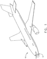
- FIG. 1 schematically illustrates an aircraft 10 with a thermal management system 11, illustrated as an on-board electronics chassis 12 (shown in phantom) for housing electronics, avionics or avionic components for use in the operation of the aircraft 10.
- the thermal management system 11 can also include heat spreaders, heat sinks, heat exchanger, radiators, phase change material, graphite straps, or heat pipes in non-limiting examples.
- the electronics chassis 12 can house a variety of electronics and avionics elements and protects them against contaminants, electromagnetic interference (EMI), radio frequency interference (RFI), shock, vibrations, temperature extremes and the like. Alternatively or additionally, the electronics chassis 12 can have a variety of avionics mounted thereon. It will be understood that the electronics chassis 12 can be located anywhere within the aircraft 10, not just the nose as illustrated.
- the electronics chassis 12 can be used in any type of aircraft, for example, without limitation, fixed-wing, rotating-wing, rocket, commercial aircraft, personal aircraft, or unmanned aircraft.
- aspects of the disclosure are not limited only to aircraft aspects, and can be included in other mobile and stationary configurations.
- Non-limiting example mobile configurations can include ground-based, water-based, or additional air-based vehicles.
- FIG. 2 illustrates the electronics chassis 12 in further detail, where the electronics chassis 12 can include a chassis housing 16 defining an interior 18 and exterior 20.
- the electronics chassis 12 can include a chassis frame 30 having a top cover 31, a bottom wall 32, a back wall 33, and opposing sidewalls 34, 35.
- the chassis frame 30 can further include a removable front cover 36, providing access to the interior 18 of the electronics chassis 12 when removed, and at least partially restricting access to the interior 18 when coupled or mounted to the chassis frame 30.
- the sidewalls 34, 35 can include an interior surface 37 and an exterior surface 38.
- the frame can be formed from any suitable material, such as metals (aluminum or steel) and non-metals in non-limiting examples.
- a set of fins 40 can project from the exterior surface 38 of the sidewalls 34, 35.
- the set of fins 40 can also be formed of any suitable material including aluminum, copper, steel, or metals with internal liquid or phase change materials. While the set of fins 40 are shown on the sidewalls 34, 35, the set of fins 40 can be disposed on any exterior portion of the electronics chassis 12, such as the top cover 31 or the bottom wall 32 in additional non-limiting examples. While the set of fins 40 are shown extending fully along the sidewalls 34, 35, it should be appreciated that the set of fins 40 need not extend the full length of the sidewalls 34, 35, and can be organized in other configurations.
- the electronics chassis 12 can further include a set of card rails 60 within the interior 18 and supported by the interior surface 37 of the sidewalls 34, 35.
- the set of card rails 60 can be horizontally (or vertically) aligned on the interior surfaces 37 and spaced on opposing sidewalls 34, 35 to define effective card slots 62 (illustrated by the phantom lines).
- An avionics system 63 including at least one avionics system card 64 can be housed within the electronics chassis 12 by way of the card slots 62, wherein each card slot 62 can be configured to receive at least a portion of an avionics system card 64.
- Each avionics system card 64 can include a set of wires 65, e.g. a wire harness or wire connectors.
- the set of wires can be formed of any suitable material, including copper or aluminum.
- at least one heat-producing electronic component 66 can be included on the avionics system card 64.
- the set of wires 65 can be used within the electronic component 66, or to connect multiple electronic components 66, or anywhere else within or on the avionics system card 64 as desired.
- the electronics chassis 12 can be configured to house, support, or include any number of avionics system cards 64.
- the avionics system card 64 can include a ceramic substrate with dies (e.g. electronic components 66) attached to the substrate.
- the avionics system 63 can further include a liquid cooling module 70, illustrated as being provided within the electronics chassis 12 and thermally coupled to the avionics system card 64 such that heat can move away from the electronic component 66 and out of the chassis 12 through the set of fins 40.
- a liquid cooling module 70 illustrated as being provided within the electronics chassis 12 and thermally coupled to the avionics system card 64 such that heat can move away from the electronic component 66 and out of the chassis 12 through the set of fins 40.
- air can be provided along the set of fins 40 to move the heat away.
- heat introduced to the exterior 20 of the electronics chassis 12 can dissipate by convection as well.
- a set of mounting feet 68 can extend from the chassis housing 16 to facilitate mounting the electronics chassis 12 to the aircraft 10 by means of bolts, wedge locks, and screws or other suitable fasteners. Further, the set of mounting feet 68 can also function as an electrical ground to ground the electronics chassis 12 to the frame of the aircraft 10. While the set of mounting feet 68 are shown in this example, the electronics chassis 12 can be used with any desired type of attachment mechanism.
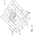
- the liquid cooling module 70 is illustrated in further detail.
- the avionics system card 64 is illustrated including the set of wires 65 and the exemplary heat-producing electronic component 66.
- the electronic component 66 in one example can be a transistor, illustrated as a silicone-carbide, metal-oxide-semiconductor field-effect transistor (SiC MOSFET). It will be understood that any desired electronic component 66 can be cooled by the cooling module 70.
- the liquid cooling module 70 can include a housing 80 supporting the electronic component 66, such as by way of fasteners.
- the housing 80 can include opposing first and second surfaces 81, 82, where the first surface 81 is adjacent the electronic component 66.
- the housing 80 can also include opposing third and fourth surfaces 83, 84 connecting the first and second surfaces 81, 82.
- the liquid cooling module 70 can further include a cold plate 90 supporting the housing 80, such as by way of fasteners.
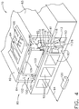
- FIG. 4 illustrates a cross-section of liquid cooling module 70 of FIG. 3 across the line A-A.
- the housing 80 can further include a cavity 85 proximate the third surface 83and containing a cooling liquid 86 represented by arrows.
- a liquid metal such as gallium, gallium alloy such as galinstan, or a Na-K alloy can be used as the cooling liquid 86.
- Other liquid metals can also be used, as well as other cooling liquids suitable for the environment of the liquid cooling module 70.
- the system card 64 can be at least partially embedded within the housing 80 such that the cooling liquid 86 can directly contact the system card 64.
- the system card 64 can be coupled to the housing 80 with no direct contact with the cooling liquid 86.
- a liquid flow channel 100 having first, second, and third portions 101, 102, 103 can be fluidly coupled to the cavity 85 and extend within the housing proximate the respective first, fourth, and second surfaces 101, 104, 102 as shown.
- the cavity 85 and liquid flow channel 100 can define a cooling loop 105 within the housing 80, and it is also contemplated that the cooling loop 105 can be a closed loop within the housing 80. In this manner the liquid flow channel 100 can be thermally coupled to the electronic component 66, where a portion of the liquid flow channel 100 runs proximate the cold plate 90.
- the cold plate 90 can include at least one cooling channel 92 through which a coolant 94 represented by arrows can flow, such as water, ethylene glycol, propylene glycol, fuel-based coolant, or oil-based coolant, in non-limiting examples. Other structures (not illustrated) such as internal heat transfer fins can also be included within the cooling channel 92. Multiple cooling channels 92 are shown in FIG. 4 , each fluidly connected to each other to form a cooling channel circuit in the cold plate 90.
- the at least one cooling channel 92 can be thermally coupled to the liquid flow channel 100, including by way of conductive contact between the cold plate 90 and housing 80.
- a pump 120 can be configured to pump coolant 94 through the cold plate 90, such as through the at least one cooling channel 92.
- the pump 120 can be positioned externally of the cold plate 90 and fluidly coupled to the at least one cooling channel 92 via appropriate conduits (not shown). In another example, the pump 120 can be positioned within the cold plate 90. It is further contemplated that the pump 120 can be configured to pump coolant 94 through the cold plate 90 cooling channels 92 at any desired rate, including with continuous flow a variable flow rate as desired.
- a double impeller 115 can be positioned between the housing 80 and the cold plate 90. More specifically, a housing impeller 110 with a plurality of spaced vanes 111 extending radially from a shaft 114 can be located or positioned within the cavity 85 of the housing 80. The vanes 111 can circulate the cooling liquid 86 through the cooling loop 105. As illustrated, the vanes 111 have a convex front surface 11 IS for pushing the cooling liquid 86 through the cavity 85 when activated. In addition, a channel impeller 112 having a plurality of spaced vanes 113 extending radially from a shaft 114 can be located or positioned within the cooling channel 92 of the cold plate 90.
- the vanes 113 have a substantially perpendicular front surface 113S for being pushed by the coolant 94 flowing through the cooling channel 92. It should be recognized that vanes 111, 113 could be of many shapes and sizes. The shape of the vanes 113 can be optimized to be pushed by the coolant 94 and the shape of the vanes 111 can be optimized to push the cooling liquid 86 in the cavity 85. In this manner, the housing impeller 110, shaft 114, and channel impeller 112 can at least partially define the double impeller 115.
- the shaft 114 can connect the housing impeller 110 to the channel impeller 112.
- apertures 116 can be formed in the housing 80 and cold plate 90 through which the shaft 114 can extend to connect the housing impeller 110 and channel impeller 112. It is further contemplated that the apertures 116 can be fluidly sealed around the shaft 114 so as to preserve a closed cooling loop 105 and prevent leakages between the housing 80 and cold plate 90. While showing the impellers 110, 112 connected via the shaft 114, it should be recognized that each impeller 110, 112 could be driven by separate and independent shafts or by separate and independent driving forces, such as a pump or other driving mechanism.
- the pump 120 can circulate coolant 94 through the cold plate 90, including through the at least one cooling channel 92.
- the channel impeller 112 can be hydraulically powered by the coolant 94, e.g. rotated by the flow of coolant 94 through the cooling channel 92.
- the channel impeller 112 can drive the housing impeller 110 via the shaft 114.
- the housing impeller 110 can rotate simultaneously with the channel impeller 112, e.g. both impellers 110, 112 having equal rotational speeds.
- other components can be included in the liquid cooling module 70 to provide for differing rotational speeds of the impellers 110, 112 as desired.
- FIG. 5 schematically illustrates heat flows during operation of the liquid cooling module 70.
- the electronic component 66 e.g. the SiC MOSFET can generate heat (illustrated with arrows 130) that can transfer, such as by conduction, to the cooling liquid 86 such as liquid metal circulating in the liquid flow channel 100.
- heat can conductively transfer (illustrated by arrows 140) from the cooling liquid 86 to the coolant 94 flowing through the cold plate 90.
- a method of cooling a heat generating electronic component includes driving rotation of the housing impeller 110 to flow a first coolant such as the cooling liquid 86 through a flow path in the housing 80 such as the liquid flow channel 100.
- the method further includes transferring heat from the electronic component to the cooling liquid 86, and transferring heat from the cooling liquid 86 to the coolant 94 as illustrated in FIG. 5 .
- the method can further include providing a cooling plate, such as the cold plate 90, for containing the coolant 94.
- the method can further include positioning the channel impeller 112 within the cold plate 90.
- the flow path such as the liquid flow channel 100 in the housing 80 can be a closed flow path.
- liquid metal flow in place of traditional cooling liquids within the housing provides for an increased heat transfer coefficient, thereby producing a more effective heat transfer mechanism to drive heat away from the electronic component, which allows for a higher power density than in traditional electronic components such as those found in avionics. It can therefore be appreciated that the liquid cooling module as described herein can increase both component reliability and cooling performance, as well as reduce the overall weight and volume of the thermal management system.
- liquid cooling module as described herein wherein a portion of the liquid flow channel runs proximate the cold plate.
- liquid cooling module as described herein wherein the housing impeller and the channel impeller rotate simultaneously.
- a method of cooling a heat generating electronic component including driving rotation of a housing impeller to flow a first coolant through a flow path in a housing supporting the electronic component, transferring heat from the electronic component to the first coolant, and transferring heat from the first coolant to a second coolant.
- the method as described herein further comprising connecting the housing impeller to a channel impeller via a shaft.
- the method as described herein further comprising driving rotation of the housing impeller via the channel impeller.
- the method as described herein further comprising providing a cooling plate for containing the second coolant.
- the method as described herein wherein the driving further comprises flowing the second coolant through a channel impeller to hydraulically drive rotation of the housing impeller.
Landscapes
- Engineering & Computer Science (AREA)
- Microelectronics & Electronic Packaging (AREA)
- Physics & Mathematics (AREA)
- Thermal Sciences (AREA)
- Aviation & Aerospace Engineering (AREA)
- Power Engineering (AREA)
- Mechanical Engineering (AREA)
- General Engineering & Computer Science (AREA)
- Cooling Or The Like Of Electrical Apparatus (AREA)
Abstract
Description
- The disclosure generally relates to a cooling module for an electronics component, and more particularly to a liquid cooling module and method of cooling a heat generating electronic component.
- Contemporary electronic power conversion systems, including those utilized in aircraft and ground vehicles to provide either AC, DC or a combination of AC and DC power to avionics and other equipment to control aircraft or ground vehicles systems. The electronic systems can also include electronic components carried by a circuit board. The circuit boards can be stored in an electronic chassis, which performs several beneficial functions including protecting avionics from lightning strikes, dissipating the heat generated by electronic components, and protecting the avionics from environmental exposure.
- Electronic components can produce high heat loads, and it can be beneficial to utilize cooling devices for managing and protecting the electronics during ground standby and in operation.
- In one aspect, the disclosure relates to a liquid cooling module for cooling an electronic component. The liquid cooling module includes a housing supporting the electronic component, where the housing includes a cavity containing a cooling liquid and also includes a liquid flow channel in fluid communication with the cavity. The liquid flow channel can define a cooling loop. The liquid cooling module can also include a cold plate supporting the housing and having a cooling channel in thermal communication with liquid flow channel, and a housing impeller positioned in the cavity for circulating the cooling liquid through the liquid cooling loop.
- Any permutation of aspects of the disclosure can also include wherein the liquid flow channel can be thermally coupled to the electronic component. Any permutation of aspects of the disclosure can also include wherein at least a portion of the liquid flow channel can run proximate the cold plate. Any permutation of aspects of the disclosure can also include wherein the cooling loop can be a closed loop, and wherein the cooling liquid can be a liquid metal. Any permutation of aspects of the disclosure can also include a coolant within the cooling channel in the cold plate. The coolant can include water, ethylene glycol, propylene glycol, fuel-based coolant, or oil-based coolant. Any permutation of aspects of the disclosure can also include a pump configured to pump the coolant through the cooling channel. Any permutation of aspects of the disclosure can also include a channel impeller located in the cooling channel in the cold plate. A shaft can connect the housing impeller to the channel impeller. Any permutation of aspects of the disclosure can also include wherein the channel impeller can drive the housing impeller via the shaft, and the housing impeller and the channel impeller can rotate simultaneously. The channel impeller can be hydraulically powered by a coolant within the cooling channel.
- In another aspect, the disclosure relates to a method of cooling a heat generating electronic component. The method includes driving rotation of a housing impeller to flow a first coolant through a flow path in a housing supporting the electronic component, transferring heat from the electronic component to the first coolant, and transferring heat from the first coolant to a second coolant.
- Any permutation of aspects of the disclosure can also include connecting the housing impeller to a channel impeller via a shaft, as well as driving rotation of the housing impeller via the channel impeller. Any permutation of aspects of the disclosure can also include providing a cooling plate for containing the second coolant. Any permutation of aspects of the disclosure can also include wherein the driving further includes flowing the second coolant through a channel impeller to hydraulically drive rotation of the housing impeller. The channel impeller can be located within the cooling plate. Any permutation of aspects of the disclosure can also include wherein the flow path in the housing is a closed flow path.
- In the drawings:
-
FIG. 1 is a perspective view of an aircraft having an electronics chassis in accordance with various aspects described herein. -
FIG. 2 is a perspective view of the exemplary electronics chassis ofFIG. 1 including a cooling module in accordance with various aspects described herein. -
FIG. 3 is a schematic view of the cooling module ofFIG. 2 . -
FIG. 4 is a cross-sectional view of the cooling module ofFIG. 3 along the line A-A illustrating liquid cooling flow. -
FIG. 5 illustrates heat flows within the cooling module ofFIG. 3 . - Aspects of the present disclosure describe an approach to form and utilize a liquid cooling module for a power supply or power conversion system. For the purposes of illustration, the cooling module of the present disclosure will be described with respect to an aircraft system. It will be understood that the present disclosure is not so limited and can have general applicability in non-aircraft applications, including solar power distribution systems, as well as in other mobile or non-mobile applications, including other air-based (helicopters, unmanned airborne vehicle), land-based (i.e., power plants, ground vehicles), or marine-based applications. Aspects of the present disclosure can also be applied to or an electronic assembly such as a ceramic pack.
- While this cooling module can have general applicability, the environment of an aircraft and specific application of an avionics chassis and electrical assembly will be described in further detail. Aspects of the liquid cooling module described herein can allow for increased heat dissipation when compared to traditional cooling modules or methods. Aircraft avionics have increasing demands and higher power density in a smaller space has seen an increasing requirement of power dissipating devices. New power generation units, conversion units, or transistors can have requirements for new materials and more efficient electrical and thermal management. By improving cooling performance, the liquid cooling module described herein can lend itself to an increased avionics power density which allows for increased computational power, or increased sensor or emitter power, supported within the physically-constrained space, weight-constrained space, or volume-constrained space.
- While "a set of' various elements will be described, it will be understood that "a set" can include any number of the respective elements, including only one element. Additionally, all directional references (e.g., radial, axial, upper, lower, upward, downward, left, right, lateral, front, back, top, bottom, above, below, vertical, horizontal, clockwise, counterclockwise) are only used for identification purposes to aid the reader's understanding of the disclosure, and do not create limitations, particularly as to the position, orientation, or use thereof. Connection references (e.g., attached, coupled, connected, and joined) are to be construed broadly and can include intermediate members between a collection of elements and relative movement between elements unless otherwise indicated. As such, connection references do not necessarily infer that two elements are directly connected and in fixed relation to each other. The exemplary drawings are for purposes of illustration only and the dimensions, positions, order and relative sizes reflected in the drawings attached hereto can vary.
-
FIG. 1 schematically illustrates anaircraft 10 with athermal management system 11, illustrated as an on-board electronics chassis 12 (shown in phantom) for housing electronics, avionics or avionic components for use in the operation of theaircraft 10. It will be understood that thethermal management system 11 can also include heat spreaders, heat sinks, heat exchanger, radiators, phase change material, graphite straps, or heat pipes in non-limiting examples. Theelectronics chassis 12 can house a variety of electronics and avionics elements and protects them against contaminants, electromagnetic interference (EMI), radio frequency interference (RFI), shock, vibrations, temperature extremes and the like. Alternatively or additionally, theelectronics chassis 12 can have a variety of avionics mounted thereon. It will be understood that theelectronics chassis 12 can be located anywhere within theaircraft 10, not just the nose as illustrated. - While illustrated in a commercial airliner, the
electronics chassis 12 can be used in any type of aircraft, for example, without limitation, fixed-wing, rotating-wing, rocket, commercial aircraft, personal aircraft, or unmanned aircraft. Furthermore, aspects of the disclosure are not limited only to aircraft aspects, and can be included in other mobile and stationary configurations. Non-limiting example mobile configurations can include ground-based, water-based, or additional air-based vehicles. -
FIG. 2 illustrates theelectronics chassis 12 in further detail, where theelectronics chassis 12 can include achassis housing 16 defining aninterior 18 andexterior 20. Theelectronics chassis 12 can include achassis frame 30 having atop cover 31, abottom wall 32, aback wall 33, and opposingsidewalls chassis frame 30 can further include a removablefront cover 36, providing access to theinterior 18 of theelectronics chassis 12 when removed, and at least partially restricting access to theinterior 18 when coupled or mounted to thechassis frame 30. In addition, thesidewalls interior surface 37 and anexterior surface 38. The frame can be formed from any suitable material, such as metals (aluminum or steel) and non-metals in non-limiting examples. - Further still, a set of
fins 40 can project from theexterior surface 38 of thesidewalls fins 40 can also be formed of any suitable material including aluminum, copper, steel, or metals with internal liquid or phase change materials. While the set offins 40 are shown on thesidewalls fins 40 can be disposed on any exterior portion of theelectronics chassis 12, such as thetop cover 31 or thebottom wall 32 in additional non-limiting examples. While the set offins 40 are shown extending fully along thesidewalls fins 40 need not extend the full length of thesidewalls - The
electronics chassis 12 can further include a set of card rails 60 within the interior 18 and supported by theinterior surface 37 of thesidewalls interior surfaces 37 and spaced on opposingsidewalls avionics system card 64 can be housed within theelectronics chassis 12 by way of thecard slots 62, wherein eachcard slot 62 can be configured to receive at least a portion of anavionics system card 64. - Each
avionics system card 64 can include a set ofwires 65, e.g. a wire harness or wire connectors. The set of wires can be formed of any suitable material, including copper or aluminum. Furthermore, at least one heat-producingelectronic component 66 can be included on theavionics system card 64. It should be understood that the set ofwires 65 can be used within theelectronic component 66, or to connect multipleelectronic components 66, or anywhere else within or on theavionics system card 64 as desired. In addition, while only oneavionics system card 64 is shown, theelectronics chassis 12 can be configured to house, support, or include any number ofavionics system cards 64. In one non-limiting example, theavionics system card 64 can include a ceramic substrate with dies (e.g. electronic components 66) attached to the substrate. - The avionics system 63 can further include a
liquid cooling module 70, illustrated as being provided within theelectronics chassis 12 and thermally coupled to theavionics system card 64 such that heat can move away from theelectronic component 66 and out of thechassis 12 through the set offins 40. By way of non-limiting example, it is contemplated that air can be provided along the set offins 40 to move the heat away. It is further contemplated that heat introduced to theexterior 20 of theelectronics chassis 12 can dissipate by convection as well. - A set of mounting
feet 68 can extend from thechassis housing 16 to facilitate mounting theelectronics chassis 12 to theaircraft 10 by means of bolts, wedge locks, and screws or other suitable fasteners. Further, the set of mountingfeet 68 can also function as an electrical ground to ground theelectronics chassis 12 to the frame of theaircraft 10. While the set of mountingfeet 68 are shown in this example, theelectronics chassis 12 can be used with any desired type of attachment mechanism. - Referring now to
FIG. 3 , theliquid cooling module 70 is illustrated in further detail. Theavionics system card 64 is illustrated including the set ofwires 65 and the exemplary heat-producingelectronic component 66. Theelectronic component 66 in one example can be a transistor, illustrated as a silicone-carbide, metal-oxide-semiconductor field-effect transistor (SiC MOSFET). It will be understood that any desiredelectronic component 66 can be cooled by thecooling module 70. Theliquid cooling module 70 can include ahousing 80 supporting theelectronic component 66, such as by way of fasteners. Thehousing 80 can include opposing first andsecond surfaces first surface 81 is adjacent theelectronic component 66. Thehousing 80 can also include opposing third andfourth surfaces second surfaces liquid cooling module 70 can further include acold plate 90 supporting thehousing 80, such as by way of fasteners. -
FIG. 4 illustrates a cross-section ofliquid cooling module 70 ofFIG. 3 across the line A-A. As illustrated, thehousing 80 can further include acavity 85 proximate the third surface 83and containing a coolingliquid 86 represented by arrows. It is contemplated in one non-limiting example that a liquid metal such as gallium, gallium alloy such as galinstan, or a Na-K alloy can be used as the coolingliquid 86. Other liquid metals can also be used, as well as other cooling liquids suitable for the environment of theliquid cooling module 70. In addition, it is further contemplated that thesystem card 64 can be at least partially embedded within thehousing 80 such that the coolingliquid 86 can directly contact thesystem card 64. In another example, thesystem card 64 can be coupled to thehousing 80 with no direct contact with the coolingliquid 86. - In addition, a
liquid flow channel 100 having first, second, andthird portions cavity 85 and extend within the housing proximate the respective first, fourth, andsecond surfaces cavity 85 andliquid flow channel 100 can define acooling loop 105 within thehousing 80, and it is also contemplated that thecooling loop 105 can be a closed loop within thehousing 80. In this manner theliquid flow channel 100 can be thermally coupled to theelectronic component 66, where a portion of theliquid flow channel 100 runs proximate thecold plate 90. - The
cold plate 90 can include at least onecooling channel 92 through which acoolant 94 represented by arrows can flow, such as water, ethylene glycol, propylene glycol, fuel-based coolant, or oil-based coolant, in non-limiting examples. Other structures (not illustrated) such as internal heat transfer fins can also be included within the coolingchannel 92.Multiple cooling channels 92 are shown inFIG. 4 , each fluidly connected to each other to form a cooling channel circuit in thecold plate 90. The at least onecooling channel 92 can be thermally coupled to theliquid flow channel 100, including by way of conductive contact between thecold plate 90 andhousing 80. Apump 120 can be configured to pumpcoolant 94 through thecold plate 90, such as through the at least onecooling channel 92. In one example, thepump 120 can be positioned externally of thecold plate 90 and fluidly coupled to the at least onecooling channel 92 via appropriate conduits (not shown). In another example, thepump 120 can be positioned within thecold plate 90. It is further contemplated that thepump 120 can be configured to pumpcoolant 94 through thecold plate 90cooling channels 92 at any desired rate, including with continuous flow a variable flow rate as desired. - It is contemplated that a
double impeller 115 can be positioned between thehousing 80 and thecold plate 90. More specifically, ahousing impeller 110 with a plurality of spacedvanes 111 extending radially from ashaft 114 can be located or positioned within thecavity 85 of thehousing 80. Thevanes 111 can circulate the coolingliquid 86 through thecooling loop 105. As illustrated, thevanes 111 have a convexfront surface 11 IS for pushing the coolingliquid 86 through thecavity 85 when activated. In addition, achannel impeller 112 having a plurality of spacedvanes 113 extending radially from ashaft 114 can be located or positioned within the coolingchannel 92 of thecold plate 90. As illustrated, thevanes 113 have a substantially perpendicularfront surface 113S for being pushed by thecoolant 94 flowing through the coolingchannel 92. It should be recognized thatvanes vanes 113 can be optimized to be pushed by thecoolant 94 and the shape of thevanes 111 can be optimized to push the coolingliquid 86 in thecavity 85. In this manner, thehousing impeller 110,shaft 114, andchannel impeller 112 can at least partially define thedouble impeller 115. - The
shaft 114 can connect thehousing impeller 110 to thechannel impeller 112. For example,apertures 116 can be formed in thehousing 80 andcold plate 90 through which theshaft 114 can extend to connect thehousing impeller 110 andchannel impeller 112. It is further contemplated that theapertures 116 can be fluidly sealed around theshaft 114 so as to preserve aclosed cooling loop 105 and prevent leakages between thehousing 80 andcold plate 90. While showing theimpellers shaft 114, it should be recognized that eachimpeller - In operation, the
pump 120 can circulatecoolant 94 through thecold plate 90, including through the at least onecooling channel 92. Thechannel impeller 112 can be hydraulically powered by thecoolant 94, e.g. rotated by the flow ofcoolant 94 through the coolingchannel 92. As such, thechannel impeller 112 can drive thehousing impeller 110 via theshaft 114. In one non-limiting example, thehousing impeller 110 can rotate simultaneously with thechannel impeller 112, e.g. bothimpellers liquid cooling module 70 to provide for differing rotational speeds of theimpellers -
FIG. 5 schematically illustrates heat flows during operation of theliquid cooling module 70. Theelectronic component 66 e.g. the SiC MOSFET can generate heat (illustrated with arrows 130) that can transfer, such as by conduction, to the coolingliquid 86 such as liquid metal circulating in theliquid flow channel 100. As the coolingliquid 86 flows along thethird portion 103, heat can conductively transfer (illustrated by arrows 140) from the coolingliquid 86 to thecoolant 94 flowing through thecold plate 90. - A method of cooling a heat generating electronic component, such as the
electronic component 66, includes driving rotation of thehousing impeller 110 to flow a first coolant such as the coolingliquid 86 through a flow path in thehousing 80 such as theliquid flow channel 100. The method further includes transferring heat from the electronic component to the coolingliquid 86, and transferring heat from the coolingliquid 86 to thecoolant 94 as illustrated inFIG. 5 . Optionally, the method can further include providing a cooling plate, such as thecold plate 90, for containing thecoolant 94. Optionally, the method can further include positioning thechannel impeller 112 within thecold plate 90. Optionally, the flow path such as theliquid flow channel 100 in thehousing 80 can be a closed flow path. - Aspects of the present disclosure provide for a variety of benefits. Traditional methods of cooling SiC MOSFETs include the use of miniature, complex-geometry channels in the housing through which the coolant can flow through. Such methods generally result in high fluid pressure drops, which can be difficult for a flow circulating pump to provide. It can be appreciated that the simplified design of the liquid cooling channel in the housing, as well as providing a closed loop for the liquid metal to circulate through, can allow for reduced manufacturing costs, improved ease of operation, and increased cooling performance.
- In addition, the use of liquid metal flow in place of traditional cooling liquids within the housing provides for an increased heat transfer coefficient, thereby producing a more effective heat transfer mechanism to drive heat away from the electronic component, which allows for a higher power density than in traditional electronic components such as those found in avionics. It can therefore be appreciated that the liquid cooling module as described herein can increase both component reliability and cooling performance, as well as reduce the overall weight and volume of the thermal management system.
- Many other possible configurations in addition to those shown in the above figures are contemplated by the present disclosure. To the extent not already described, the different features and structures of the various aspects can be used in combination with others as desired. That one feature cannot be illustrated in all of the aspects is not meant to be construed that it cannot be, but is done for brevity of description. Thus, the various features of the different aspects can be mixed and matched as desired to form new aspects, whether or not the new aspects are expressly described. Combinations or permutations of features described herein are covered by this disclosure.
- This written description uses examples to disclose aspects of the invention, including the best mode, and also to enable any person skilled in the art to practice aspects of the invention, including making and using any devices or systems and performing any incorporated methods. The patentable scope of the invention is defined by the claims, and can include other examples that occur to those skilled in the art. Such other examples are intended to be within the scope of the claims if they have structural elements that do not differ from the literal language of the claims, or if they include equivalent structural elements with insubstantial differences from the literal languages of the claims.
- Various characteristics, aspects, and advantages of the present invention may also be embodied in the following technical solutions as defined by the clauses:
- The liquid cooling module as described herein wherein a portion of the liquid flow channel runs proximate the cold plate.
- The liquid cooling module as described herein wherein the coolant comprises one of water, ethylene glycol, propylene glycol, fuel-based coolant, or oil-based coolant.
- The liquid cooling module as described herein wherein the housing impeller and the channel impeller rotate simultaneously.
- A method of cooling a heat generating electronic component, the method including driving rotation of a housing impeller to flow a first coolant through a flow path in a housing supporting the electronic component, transferring heat from the electronic component to the first coolant, and transferring heat from the first coolant to a second coolant.
- The method as described herein further comprising connecting the housing impeller to a channel impeller via a shaft.
- The method as described herein further comprising driving rotation of the housing impeller via the channel impeller.
- The method as described herein further comprising providing a cooling plate for containing the second coolant.
- The method as described herein wherein the driving further comprises flowing the second coolant through a channel impeller to hydraulically drive rotation of the housing impeller.
- The method as described herein wherein the channel impeller is located within the cooling plate.
- The method as described herein wherein the flow path in the housing is a closed flow path.
Claims (10)
- A liquid cooling module (70) for cooling an electronic component (66), comprising:a housing (80) supporting the electronic component (66), the housing (80) having a cavity (85) containing a cooling liquid (86) and also having a liquid flow channel (100) in fluid communication with the cavity (85), the liquid flow channel (100) defining a cooling loop (105);a cold plate (90) supporting the housing (80) and having a cooling channel (92) thermally coupled to the liquid flow channel (100); anda housing impeller (110) positioned in the cavity (85) for circulating the cooling liquid (86) through the cooling loop (105).
- The liquid cooling module (70) of claim 1 wherein the liquid flow channel (100) is thermally coupled to the electronic component (66).
- The liquid cooling module (70) of any of claims 1-2 wherein the cooling loop (105) is a closed loop.
- The liquid cooling module (70) of claims 1-3 wherein the cooling liquid (86) is a liquid metal.
- The liquid cooling module (70) of claims 1-4 further comprising a coolant (94) within the cooling channel (92) in the cold plate (90).
- The liquid cooling module (70) of any of claims 1-5 further comprising a pump (120) configured to pump the coolant (94) through the cooling channel (92).
- The liquid cooling module (70) of claims 1-6 further comprising a channel impeller (112) located in the cooling channel (92) in the cold plate (90).
- The liquid cooling module (70) of claim 7 further comprising a shaft (114) connecting the housing impeller (110) to the channel impeller (112).
- The liquid cooling module (70) of claim 8 wherein the channel impeller (112) drives the housing impeller (110) via the shaft (114).
- The liquid cooling module (70) of any of claims 7-9 wherein the channel impeller (112) is hydraulically powered by a coolant (94) within the cooling channel (92).
Applications Claiming Priority (1)
| Application Number | Priority Date | Filing Date | Title |
|---|---|---|---|
| US15/955,299 US10645844B2 (en) | 2018-04-17 | 2018-04-17 | Electronics cooling module |
Publications (2)
| Publication Number | Publication Date |
|---|---|
| EP3557964A1 true EP3557964A1 (en) | 2019-10-23 |
| EP3557964B1 EP3557964B1 (en) | 2022-11-09 |
Family
ID=66175335
Family Applications (1)
| Application Number | Title | Priority Date | Filing Date |
|---|---|---|---|
| EP19169118.7A Active EP3557964B1 (en) | 2018-04-17 | 2019-04-12 | Electronics cooling module |
Country Status (3)
| Country | Link |
|---|---|
| US (1) | US10645844B2 (en) |
| EP (1) | EP3557964B1 (en) |
| CN (1) | CN110391598B (en) |
Families Citing this family (8)
| Publication number | Priority date | Publication date | Assignee | Title |
|---|---|---|---|---|
| US11539109B2 (en) * | 2020-03-26 | 2022-12-27 | Hamilton Sundstrand Corporation | Heat exchanger rib for multi-function aperture |
| CN111585184A (en) * | 2020-06-12 | 2020-08-25 | 安徽万华电气股份有限公司 | Switch cabinet with internal environment detection function and use method thereof |
| US11770062B2 (en) * | 2020-08-07 | 2023-09-26 | Apple Inc. | Liquid heat exchanger for electronic device |
| US12004332B2 (en) | 2021-01-14 | 2024-06-04 | Alliance For Sustainable Energy, Llc | Cooling automotive power electronics |
| US20230254996A1 (en) * | 2022-02-07 | 2023-08-10 | Scot Arthur Johnson | Immersion tank assembly |
| CN217957565U (en) * | 2022-04-28 | 2022-12-02 | 华为数字能源技术有限公司 | Packaging structure |
| US12295122B2 (en) | 2023-05-10 | 2025-05-06 | Bae Systems Information And Electronic Systems Integration Inc. | Coolant flow partition for cooling 3U boards in 6U chassis |
| US12178010B2 (en) * | 2023-05-10 | 2024-12-24 | Bae Systems Information And Electronic Systems Integration Inc. | Additive manufacturing compatible liquid-cooled PCB chassis |
Citations (6)
| Publication number | Priority date | Publication date | Assignee | Title |
|---|---|---|---|---|
| US20080173427A1 (en) * | 2007-01-23 | 2008-07-24 | Richard Schumacher | Electronic component cooling |
| US20090038781A1 (en) * | 2004-07-08 | 2009-02-12 | Jurgen Hertweck | Heat Exchange System |
| US8017872B2 (en) * | 2008-05-06 | 2011-09-13 | Rockwell Collins, Inc. | System and method for proportional cooling with liquid metal |
| US20140352928A1 (en) * | 2012-03-21 | 2014-12-04 | Huawei Technologies Co., Ltd. | Electronic Device, and Heat Dissipation System and Heat Dissipation Method of Electronic Device |
| CN204259336U (en) * | 2014-11-19 | 2015-04-08 | 中国航空工业集团公司西安飞机设计研究所 | A kind of cabinet cooling device |
| US20170027081A1 (en) * | 2015-07-20 | 2017-01-26 | Asia Vital Components Co., Ltd. | Liquid-cooling device and system thereof |
Family Cites Families (16)
| Publication number | Priority date | Publication date | Assignee | Title |
|---|---|---|---|---|
| WO2005061972A1 (en) | 2002-12-06 | 2005-07-07 | Nanocoolers, Inc. | Cooling of electronics by electrically conducting fluids |
| US20050099775A1 (en) | 2003-11-12 | 2005-05-12 | Himanshu Pokharna | Pumped liquid cooling for computer systems using liquid metal coolant |
| US20050145371A1 (en) | 2003-12-31 | 2005-07-07 | Eric Distefano | Thermal solution for electronics cooling using a heat pipe in combination with active loop solution |
| US7340904B2 (en) | 2004-10-29 | 2008-03-11 | Intel Corporation | Method and apparatus for removing heat |
| US7265977B2 (en) | 2005-01-18 | 2007-09-04 | International Business Machines Corporation | Active liquid metal thermal spreader |
| US8174830B2 (en) | 2008-05-06 | 2012-05-08 | Rockwell Collins, Inc. | System and method for a substrate with internal pumped liquid metal for thermal spreading and cooling |
| US20090038780A1 (en) * | 2007-08-10 | 2009-02-12 | Kechuan Kevin Liu | Pumpless liquid cooling system |
| US8522570B2 (en) | 2008-06-13 | 2013-09-03 | Oracle America, Inc. | Integrated circuit chip cooling using magnetohydrodynamics and recycled power |
| US20110308783A1 (en) * | 2010-06-17 | 2011-12-22 | Mark Randal Nicewonger | Fluid-powered heat exchanger apparatus for cooling electronic equipment |
| FR2984074B1 (en) | 2011-12-13 | 2014-11-28 | Hispano Suiza Sa | ELECTRONIC DEVICE WITH LIQUID METAL SPREADER COOLING |
| FR3010830B1 (en) * | 2013-09-17 | 2016-12-23 | Commissariat Energie Atomique | DEVICE FOR COOLING AN INTEGRATED CIRCUIT CHIP |
| US9894802B2 (en) | 2014-05-29 | 2018-02-13 | Ge-Hitachi Nuclear Energy Americas Llc | Passive system of powering and cooling with liquid metal and method thereof |
| JP6555081B2 (en) * | 2015-10-30 | 2019-08-07 | 富士通株式会社 | Sealed loop circulating liquid cooling device and electronic equipment |
| US10264712B2 (en) * | 2015-11-24 | 2019-04-16 | Lenovo Enterprise Solutions (Singapore) Pte. Ltd. | Harvesting facility water for pumping secondary fluid flow |
| CN107438348B (en) * | 2016-05-27 | 2023-12-15 | 奇鋐科技股份有限公司 | Water cooling device |
| CN207118186U (en) * | 2017-06-28 | 2018-03-16 | 云南靖创液态金属热控技术研发有限公司 | A kind of LED display |
-
2018
- 2018-04-17 US US15/955,299 patent/US10645844B2/en active Active
-
2019
- 2019-04-12 EP EP19169118.7A patent/EP3557964B1/en active Active
- 2019-04-17 CN CN201910309378.2A patent/CN110391598B/en active Active
Patent Citations (6)
| Publication number | Priority date | Publication date | Assignee | Title |
|---|---|---|---|---|
| US20090038781A1 (en) * | 2004-07-08 | 2009-02-12 | Jurgen Hertweck | Heat Exchange System |
| US20080173427A1 (en) * | 2007-01-23 | 2008-07-24 | Richard Schumacher | Electronic component cooling |
| US8017872B2 (en) * | 2008-05-06 | 2011-09-13 | Rockwell Collins, Inc. | System and method for proportional cooling with liquid metal |
| US20140352928A1 (en) * | 2012-03-21 | 2014-12-04 | Huawei Technologies Co., Ltd. | Electronic Device, and Heat Dissipation System and Heat Dissipation Method of Electronic Device |
| CN204259336U (en) * | 2014-11-19 | 2015-04-08 | 中国航空工业集团公司西安飞机设计研究所 | A kind of cabinet cooling device |
| US20170027081A1 (en) * | 2015-07-20 | 2017-01-26 | Asia Vital Components Co., Ltd. | Liquid-cooling device and system thereof |
Also Published As
| Publication number | Publication date |
|---|---|
| CN110391598B (en) | 2022-02-18 |
| US20190320556A1 (en) | 2019-10-17 |
| US10645844B2 (en) | 2020-05-05 |
| EP3557964B1 (en) | 2022-11-09 |
| CN110391598A (en) | 2019-10-29 |
Similar Documents
| Publication | Publication Date | Title |
|---|---|---|
| EP3557964B1 (en) | Electronics cooling module | |
| US20220007546A1 (en) | Apparatus for increasing heat dissipation capacity of a din rail mounted enclosure | |
| EP1599081B1 (en) | Thermal management system and method for electronic equipment mounted on coldplates | |
| EP2321849B1 (en) | Liquid submerged, horizontal computer server rack and systems and methods of cooling such a server rack | |
| US5315830A (en) | Modular thermoelectric assembly | |
| US10980153B2 (en) | Direct contact heat exchanger | |
| EP3629690A1 (en) | Cold plate for power module | |
| EP3968457A1 (en) | Vehicle-body antenna module and method for cooling a vehicle-body antenna module | |
| US6219245B1 (en) | Electrically isolated power switching device mounting assembly for EMI reduction | |
| US9545037B2 (en) | Systems and methods for cooling electric drives | |
| US7312992B2 (en) | Apparatus and method for transferring heat from processors | |
| WO2008141170A1 (en) | Thermal management systems and methods for electronic components in a sealed enclosure | |
| EP3573438A1 (en) | Remote heat exchanger | |
| US20090279259A1 (en) | System and method for proportional cooling with liquid metal | |
| US10822096B2 (en) | Avionics cooling module | |
| US10874034B1 (en) | Pump driven liquid cooling module with tower fins | |
| US20180177072A1 (en) | Electronics chassis assembly | |
| US12245407B2 (en) | Aircraft and method for thermal management | |
| WO2026031826A1 (en) | Computing device and vehicle | |
| GB2298995A (en) | Base station | |
| EP3206470A1 (en) | Frame for holding an electronic board, housing, and rack including frame and housing | |
| CN209861420U (en) | Module power supply mounting structure | |
| CN216564896U (en) | Cooling structure of traction converter | |
| JPH09293813A (en) | Sealed self-cooling case with oil |
Legal Events
| Date | Code | Title | Description |
|---|---|---|---|
| PUAI | Public reference made under article 153(3) epc to a published international application that has entered the european phase |
Free format text: ORIGINAL CODE: 0009012 |
|
| STAA | Information on the status of an ep patent application or granted ep patent |
Free format text: STATUS: THE APPLICATION HAS BEEN PUBLISHED |
|
| AK | Designated contracting states |
Kind code of ref document: A1 Designated state(s): AL AT BE BG CH CY CZ DE DK EE ES FI FR GB GR HR HU IE IS IT LI LT LU LV MC MK MT NL NO PL PT RO RS SE SI SK SM TR |
|
| AX | Request for extension of the european patent |
Extension state: BA ME |
|
| STAA | Information on the status of an ep patent application or granted ep patent |
Free format text: STATUS: REQUEST FOR EXAMINATION WAS MADE |
|
| 17P | Request for examination filed |
Effective date: 20200318 |
|
| RBV | Designated contracting states (corrected) |
Designated state(s): AL AT BE BG CH CY CZ DE DK EE ES FI FR GB GR HR HU IE IS IT LI LT LU LV MC MK MT NL NO PL PT RO RS SE SI SK SM TR |
|
| STAA | Information on the status of an ep patent application or granted ep patent |
Free format text: STATUS: EXAMINATION IS IN PROGRESS |
|
| 17Q | First examination report despatched |
Effective date: 20210810 |
|
| GRAP | Despatch of communication of intention to grant a patent |
Free format text: ORIGINAL CODE: EPIDOSNIGR1 |
|
| STAA | Information on the status of an ep patent application or granted ep patent |
Free format text: STATUS: GRANT OF PATENT IS INTENDED |
|
| INTG | Intention to grant announced |
Effective date: 20220531 |
|
| RIN1 | Information on inventor provided before grant (corrected) |
Inventor name: YANG, LIQIANG Inventor name: ENGELHARDT, MICHEL Inventor name: DARIAVACH, NADER |
|
| GRAS | Grant fee paid |
Free format text: ORIGINAL CODE: EPIDOSNIGR3 |
|
| GRAA | (expected) grant |
Free format text: ORIGINAL CODE: 0009210 |
|
| STAA | Information on the status of an ep patent application or granted ep patent |
Free format text: STATUS: THE PATENT HAS BEEN GRANTED |
|
| AK | Designated contracting states |
Kind code of ref document: B1 Designated state(s): AL AT BE BG CH CY CZ DE DK EE ES FI FR GB GR HR HU IE IS IT LI LT LU LV MC MK MT NL NO PL PT RO RS SE SI SK SM TR |
|
| REG | Reference to a national code |
Ref country code: GB Ref legal event code: FG4D |
|
| REG | Reference to a national code |
Ref country code: CH Ref legal event code: EP Ref country code: AT Ref legal event code: REF Ref document number: 1531169 Country of ref document: AT Kind code of ref document: T Effective date: 20221115 |
|
| REG | Reference to a national code |
Ref country code: DE Ref legal event code: R096 Ref document number: 602019021601 Country of ref document: DE |
|
| REG | Reference to a national code |
Ref country code: IE Ref legal event code: FG4D |
|
| REG | Reference to a national code |
Ref country code: LT Ref legal event code: MG9D |
|
| REG | Reference to a national code |
Ref country code: NL Ref legal event code: MP Effective date: 20221109 |
|
| REG | Reference to a national code |
Ref country code: AT Ref legal event code: MK05 Ref document number: 1531169 Country of ref document: AT Kind code of ref document: T Effective date: 20221109 |
|
| PG25 | Lapsed in a contracting state [announced via postgrant information from national office to epo] |
Ref country code: SE Free format text: LAPSE BECAUSE OF FAILURE TO SUBMIT A TRANSLATION OF THE DESCRIPTION OR TO PAY THE FEE WITHIN THE PRESCRIBED TIME-LIMIT Effective date: 20221109 Ref country code: PT Free format text: LAPSE BECAUSE OF FAILURE TO SUBMIT A TRANSLATION OF THE DESCRIPTION OR TO PAY THE FEE WITHIN THE PRESCRIBED TIME-LIMIT Effective date: 20230309 Ref country code: NO Free format text: LAPSE BECAUSE OF FAILURE TO SUBMIT A TRANSLATION OF THE DESCRIPTION OR TO PAY THE FEE WITHIN THE PRESCRIBED TIME-LIMIT Effective date: 20230209 Ref country code: LT Free format text: LAPSE BECAUSE OF FAILURE TO SUBMIT A TRANSLATION OF THE DESCRIPTION OR TO PAY THE FEE WITHIN THE PRESCRIBED TIME-LIMIT Effective date: 20221109 Ref country code: FI Free format text: LAPSE BECAUSE OF FAILURE TO SUBMIT A TRANSLATION OF THE DESCRIPTION OR TO PAY THE FEE WITHIN THE PRESCRIBED TIME-LIMIT Effective date: 20221109 Ref country code: ES Free format text: LAPSE BECAUSE OF FAILURE TO SUBMIT A TRANSLATION OF THE DESCRIPTION OR TO PAY THE FEE WITHIN THE PRESCRIBED TIME-LIMIT Effective date: 20221109 Ref country code: AT Free format text: LAPSE BECAUSE OF FAILURE TO SUBMIT A TRANSLATION OF THE DESCRIPTION OR TO PAY THE FEE WITHIN THE PRESCRIBED TIME-LIMIT Effective date: 20221109 |
|
| PG25 | Lapsed in a contracting state [announced via postgrant information from national office to epo] |
Ref country code: RS Free format text: LAPSE BECAUSE OF FAILURE TO SUBMIT A TRANSLATION OF THE DESCRIPTION OR TO PAY THE FEE WITHIN THE PRESCRIBED TIME-LIMIT Effective date: 20221109 Ref country code: PL Free format text: LAPSE BECAUSE OF FAILURE TO SUBMIT A TRANSLATION OF THE DESCRIPTION OR TO PAY THE FEE WITHIN THE PRESCRIBED TIME-LIMIT Effective date: 20221109 Ref country code: LV Free format text: LAPSE BECAUSE OF FAILURE TO SUBMIT A TRANSLATION OF THE DESCRIPTION OR TO PAY THE FEE WITHIN THE PRESCRIBED TIME-LIMIT Effective date: 20221109 Ref country code: IS Free format text: LAPSE BECAUSE OF FAILURE TO SUBMIT A TRANSLATION OF THE DESCRIPTION OR TO PAY THE FEE WITHIN THE PRESCRIBED TIME-LIMIT Effective date: 20230309 Ref country code: HR Free format text: LAPSE BECAUSE OF FAILURE TO SUBMIT A TRANSLATION OF THE DESCRIPTION OR TO PAY THE FEE WITHIN THE PRESCRIBED TIME-LIMIT Effective date: 20221109 Ref country code: GR Free format text: LAPSE BECAUSE OF FAILURE TO SUBMIT A TRANSLATION OF THE DESCRIPTION OR TO PAY THE FEE WITHIN THE PRESCRIBED TIME-LIMIT Effective date: 20230210 |
|
| P01 | Opt-out of the competence of the unified patent court (upc) registered |
Effective date: 20230411 |
|
| PG25 | Lapsed in a contracting state [announced via postgrant information from national office to epo] |
Ref country code: NL Free format text: LAPSE BECAUSE OF FAILURE TO SUBMIT A TRANSLATION OF THE DESCRIPTION OR TO PAY THE FEE WITHIN THE PRESCRIBED TIME-LIMIT Effective date: 20221109 |
|
| PG25 | Lapsed in a contracting state [announced via postgrant information from national office to epo] |
Ref country code: SM Free format text: LAPSE BECAUSE OF FAILURE TO SUBMIT A TRANSLATION OF THE DESCRIPTION OR TO PAY THE FEE WITHIN THE PRESCRIBED TIME-LIMIT Effective date: 20221109 Ref country code: RO Free format text: LAPSE BECAUSE OF FAILURE TO SUBMIT A TRANSLATION OF THE DESCRIPTION OR TO PAY THE FEE WITHIN THE PRESCRIBED TIME-LIMIT Effective date: 20221109 Ref country code: EE Free format text: LAPSE BECAUSE OF FAILURE TO SUBMIT A TRANSLATION OF THE DESCRIPTION OR TO PAY THE FEE WITHIN THE PRESCRIBED TIME-LIMIT Effective date: 20221109 Ref country code: DK Free format text: LAPSE BECAUSE OF FAILURE TO SUBMIT A TRANSLATION OF THE DESCRIPTION OR TO PAY THE FEE WITHIN THE PRESCRIBED TIME-LIMIT Effective date: 20221109 Ref country code: CZ Free format text: LAPSE BECAUSE OF FAILURE TO SUBMIT A TRANSLATION OF THE DESCRIPTION OR TO PAY THE FEE WITHIN THE PRESCRIBED TIME-LIMIT Effective date: 20221109 |
|
| REG | Reference to a national code |
Ref country code: DE Ref legal event code: R097 Ref document number: 602019021601 Country of ref document: DE |
|
| PG25 | Lapsed in a contracting state [announced via postgrant information from national office to epo] |
Ref country code: SK Free format text: LAPSE BECAUSE OF FAILURE TO SUBMIT A TRANSLATION OF THE DESCRIPTION OR TO PAY THE FEE WITHIN THE PRESCRIBED TIME-LIMIT Effective date: 20221109 Ref country code: AL Free format text: LAPSE BECAUSE OF FAILURE TO SUBMIT A TRANSLATION OF THE DESCRIPTION OR TO PAY THE FEE WITHIN THE PRESCRIBED TIME-LIMIT Effective date: 20221109 |
|
| PLBE | No opposition filed within time limit |
Free format text: ORIGINAL CODE: 0009261 |
|
| STAA | Information on the status of an ep patent application or granted ep patent |
Free format text: STATUS: NO OPPOSITION FILED WITHIN TIME LIMIT |
|
| 26N | No opposition filed |
Effective date: 20230810 |
|
| PG25 | Lapsed in a contracting state [announced via postgrant information from national office to epo] |
Ref country code: SI Free format text: LAPSE BECAUSE OF FAILURE TO SUBMIT A TRANSLATION OF THE DESCRIPTION OR TO PAY THE FEE WITHIN THE PRESCRIBED TIME-LIMIT Effective date: 20221109 |
|
| REG | Reference to a national code |
Ref country code: CH Ref legal event code: PL |
|
| PG25 | Lapsed in a contracting state [announced via postgrant information from national office to epo] |
Ref country code: LU Free format text: LAPSE BECAUSE OF NON-PAYMENT OF DUE FEES Effective date: 20230412 |
|
| REG | Reference to a national code |
Ref country code: BE Ref legal event code: MM Effective date: 20230430 |
|
| PG25 | Lapsed in a contracting state [announced via postgrant information from national office to epo] |
Ref country code: MC Free format text: LAPSE BECAUSE OF FAILURE TO SUBMIT A TRANSLATION OF THE DESCRIPTION OR TO PAY THE FEE WITHIN THE PRESCRIBED TIME-LIMIT Effective date: 20221109 |
|
| PG25 | Lapsed in a contracting state [announced via postgrant information from national office to epo] |
Ref country code: MC Free format text: LAPSE BECAUSE OF FAILURE TO SUBMIT A TRANSLATION OF THE DESCRIPTION OR TO PAY THE FEE WITHIN THE PRESCRIBED TIME-LIMIT Effective date: 20221109 Ref country code: LI Free format text: LAPSE BECAUSE OF NON-PAYMENT OF DUE FEES Effective date: 20230430 Ref country code: CH Free format text: LAPSE BECAUSE OF NON-PAYMENT OF DUE FEES Effective date: 20230430 |
|
| REG | Reference to a national code |
Ref country code: IE Ref legal event code: MM4A |
|
| PG25 | Lapsed in a contracting state [announced via postgrant information from national office to epo] |
Ref country code: BE Free format text: LAPSE BECAUSE OF NON-PAYMENT OF DUE FEES Effective date: 20230430 |
|
| PG25 | Lapsed in a contracting state [announced via postgrant information from national office to epo] |
Ref country code: IE Free format text: LAPSE BECAUSE OF NON-PAYMENT OF DUE FEES Effective date: 20230412 |
|
| PG25 | Lapsed in a contracting state [announced via postgrant information from national office to epo] |
Ref country code: IE Free format text: LAPSE BECAUSE OF NON-PAYMENT OF DUE FEES Effective date: 20230412 |
|
| PG25 | Lapsed in a contracting state [announced via postgrant information from national office to epo] |
Ref country code: IT Free format text: LAPSE BECAUSE OF FAILURE TO SUBMIT A TRANSLATION OF THE DESCRIPTION OR TO PAY THE FEE WITHIN THE PRESCRIBED TIME-LIMIT Effective date: 20221109 |
|
| PG25 | Lapsed in a contracting state [announced via postgrant information from national office to epo] |
Ref country code: BG Free format text: LAPSE BECAUSE OF FAILURE TO SUBMIT A TRANSLATION OF THE DESCRIPTION OR TO PAY THE FEE WITHIN THE PRESCRIBED TIME-LIMIT Effective date: 20221109 |
|
| PG25 | Lapsed in a contracting state [announced via postgrant information from national office to epo] |
Ref country code: BG Free format text: LAPSE BECAUSE OF FAILURE TO SUBMIT A TRANSLATION OF THE DESCRIPTION OR TO PAY THE FEE WITHIN THE PRESCRIBED TIME-LIMIT Effective date: 20221109 |
|
| PGFP | Annual fee paid to national office [announced via postgrant information from national office to epo] |
Ref country code: DE Payment date: 20250319 Year of fee payment: 7 |
|
| PG25 | Lapsed in a contracting state [announced via postgrant information from national office to epo] |
Ref country code: CY Free format text: LAPSE BECAUSE OF FAILURE TO SUBMIT A TRANSLATION OF THE DESCRIPTION OR TO PAY THE FEE WITHIN THE PRESCRIBED TIME-LIMIT; INVALID AB INITIO Effective date: 20190412 |
|
| PG25 | Lapsed in a contracting state [announced via postgrant information from national office to epo] |
Ref country code: HU Free format text: LAPSE BECAUSE OF FAILURE TO SUBMIT A TRANSLATION OF THE DESCRIPTION OR TO PAY THE FEE WITHIN THE PRESCRIBED TIME-LIMIT; INVALID AB INITIO Effective date: 20190412 |
|
| PG25 | Lapsed in a contracting state [announced via postgrant information from national office to epo] |
Ref country code: TR Free format text: LAPSE BECAUSE OF FAILURE TO SUBMIT A TRANSLATION OF THE DESCRIPTION OR TO PAY THE FEE WITHIN THE PRESCRIBED TIME-LIMIT Effective date: 20221109 |
|
| PGFP | Annual fee paid to national office [announced via postgrant information from national office to epo] |
Ref country code: GB Payment date: 20260319 Year of fee payment: 8 |
|
| PGFP | Annual fee paid to national office [announced via postgrant information from national office to epo] |
Ref country code: FR Payment date: 20260320 Year of fee payment: 8 |