EP3557959B1 - Waterproof power supply - Google Patents
Waterproof power supply Download PDFInfo
- Publication number
- EP3557959B1 EP3557959B1 EP19170172.1A EP19170172A EP3557959B1 EP 3557959 B1 EP3557959 B1 EP 3557959B1 EP 19170172 A EP19170172 A EP 19170172A EP 3557959 B1 EP3557959 B1 EP 3557959B1
- Authority
- EP
- European Patent Office
- Prior art keywords
- housing
- power supply
- end cover
- cavity
- waterproof
- Prior art date
- Legal status (The legal status is an assumption and is not a legal conclusion. Google has not performed a legal analysis and makes no representation as to the accuracy of the status listed.)
- Active
Links
Images


Classifications
-
- H—ELECTRICITY
- H05—ELECTRIC TECHNIQUES NOT OTHERWISE PROVIDED FOR
- H05K—PRINTED CIRCUITS; CASINGS OR CONSTRUCTIONAL DETAILS OF ELECTRIC APPARATUS; MANUFACTURE OF ASSEMBLAGES OF ELECTRICAL COMPONENTS
- H05K5/00—Casings, cabinets or drawers for electric apparatus
- H05K5/06—Hermetically-sealed casings
- H05K5/064—Hermetically-sealed casings sealed by potting, e.g. waterproof resin poured in a rigid casing
-
- H—ELECTRICITY
- H05—ELECTRIC TECHNIQUES NOT OTHERWISE PROVIDED FOR
- H05K—PRINTED CIRCUITS; CASINGS OR CONSTRUCTIONAL DETAILS OF ELECTRIC APPARATUS; MANUFACTURE OF ASSEMBLAGES OF ELECTRICAL COMPONENTS
- H05K5/00—Casings, cabinets or drawers for electric apparatus
- H05K5/06—Hermetically-sealed casings
- H05K5/062—Hermetically-sealed casings sealed by a material injected between a non-removable cover and a body, e.g. hardening in situ
-
- H—ELECTRICITY
- H05—ELECTRIC TECHNIQUES NOT OTHERWISE PROVIDED FOR
- H05K—PRINTED CIRCUITS; CASINGS OR CONSTRUCTIONAL DETAILS OF ELECTRIC APPARATUS; MANUFACTURE OF ASSEMBLAGES OF ELECTRICAL COMPONENTS
- H05K5/00—Casings, cabinets or drawers for electric apparatus
- H05K5/06—Hermetically-sealed casings
- H05K5/069—Other details of the casing, e.g. wall structure, passage for a connector, a cable, a shaft
Definitions
- the present invention relates to electronic field, with particular emphasis on a waterproof power supply.
- the waterproof power supply on the market is mainly used to pour the potting glue into the power supply or to set the silicone gasket in the power supply to achieve a waterproof effect.
- the former waterproof method is to vacuum the inside of the power supply before filling the glue, and then refill the glue, vacuuming can avoid the air holes in the no-fill sealant, which makes it possible for water vapor to enter through the air holes to short-circuit the components in the power supply;
- the invention patent CN102055303B mainly embodies the latter waterproof method, that is, the waterproof gasket is set in the power supply device for waterproof.
- JP 2007 207768 A discloses a waterproof structure of a tubular case end.
- a hollow is provided on an outer peripheral surface of a sealing plug inserted into the tubular case end, a filling material is injected from a hole provided on an outer surface of the sealing plug in the hollow and a space part formed on an inner face of the tubular case, the tubular case is formed with a structure discharging the air in the space part from a groove or a hole of the sealing plug formed independently, and a waterproof case covers its outside to make up the waterproof structure.
- CN 203 784 891 U discloses a waterproof drive power supply comprising a housing with openings at the two ends, and a power panel fixedly mounted in the housing; the two ends of the power panel are connected with conducting wires respectively; an end cover is arranged at the opening of each end of the housing; conducting wire holes are formed in each end cover; an inner plug nested in the housing and provided with openings is arranged between the end cover and the power panel which are positioned on the same side, and a gap is reserved between the inner plug and the end cover to form a glue injection cavity; glue injection holes communicated with the glue injection cavities are formed in the housing; sealant blocks formed by injection molding are arranged in the glue injection cavities.
- the consumption of glue is only 20% of the consumption of glue used in the prior art
- the curing time is greatly shortened, the production efficiency is improved, the direct contact between glue and an electric element is prevented, and the phenomenathat the displacement caused by tension generated by thermal expansion and cold shrinkage of the glue to the electric element, of the electric element is caused, the glue cracks after curing, and the electric element directly suffers from corrosion damage can be avoided, thereby improving the stability of the product quality, and reducing the cost.
- EP 3 177 119 A1 discloses a waterproof case for an electrical apparatus, a power supply unit, and to a corresponding method of assembling an electrical apparatus.
- the waterproof case comprises a case body which defines an inner space for accommodating an electrically functional component and which comprises at least one first opening, at least one first plug which is mounted in said first opening to form a first part of a wall of the inner space, wherein the first plug comprises at least one first terminal conduit forming a feedthrough for a first terminal.
- the first plug is arranged in said first opening to form with said case body a first external space, and said first external space is filled with an electrically insulating material for sealing said waterproof case.
- an object of the present invention is to provide a waterproof power supply which has good waterproof effect and high production efficiency.
- the invention also aims to provide a waterproof power supply with simple structure.
- a waterproof power supply including, housing, the housing is provided with built-in power supply component; end cover, the end cover is connected to the opening on the housing; the end cover and the opening of the housing form a sealed cavity and the sealing of end cover and housing can be realized by injecting colloid into the cavity.
- the end cover includes two oppositely disposed and connected baffles, and the cavity is formed by the enclosure of two baffles and the side wall of the housing.
- the two baffles are conductive plates and are electrically connected;
- the power supply component is a circuit motherboard, the baffle on the inner side of the end cover is connected with one end of the circuit motherboard;
- the end cover is further provided with power cord, and the power cord is connected at least to the baffle on the outer side of the end cover, and the two baffles are connected through a conductive connector.
- the baffle on the outer side of the end cover is provided with injection hole and overflow hole, the colloid is injected into the cavity from the injection hole, the air in the cavity is discharged from the overflow hole during the injection process, and the colloid overflows from the overflow hole after the colloid is filled with the cavity.
- the housing is integrally formed.
- two openings are formed on the housing, respectively located at two ends of the housing.
- two baffles are integrally formed.
- the invention has the advantages that the end cover and the opening of the housing form a cavity, and the end cover is provided with injection hole and overflow hole, when the colloid is injected through the injection hole, the air in the cavity is continuously eliminated from the overflow hole in the process of colloid injection. When the colloid is filled, it will overflow from the overflow hole.
- the structure effectively overcomes the complicated process of removing gas from the housing by vacuuming, which is convenient and fast, and the cost is low, and the effect is good; Meanwhile, the entire power supply is in contact with the circuit board through the conductive plate of the end cover, that is to achieve the conductive transmission of power, this structure simplifies the internal structure of the power supply, but also firm and stable, reduce the production cost.
- the present application relates to a waterproof power supply including a housing 1 having a power supply component 2 disposed therein, the housing 1 is provided with an opening 11.
- the waterproof power supply also includes end cover 3 which is connected to the opening 11 on the housing 1.
- the end cover 3 and the opening 11 of the housing 1 can cooperate to form a relatively sealed cavity in the present application, and the sealing of end cover and housing can be realized by injecting colloid into the cavity, and then the whole housing can be sealed for effective waterproof.
- FIG.1-3 shows a structural diagram of the waterproof power supply of the present invention, but it needs to be noted that here is one embodiment structure of the present invention is shown here, but not limited to this structure, other power structures that can achieve the functions and effects described in this application also fall within the scope of protection of this application.
- the end cover 3 includes two oppositely disposed and connected baffles 31, 32, and the cavity is formed by the enclosure of two baffles 31 and 32 and the side wall of the housing 1.
- the baffle 31 on the outer side of the end cover 3 is provided with injection hole 33 and overflow hole 34.
- the colloid is injected into the cavity from the injection hole 33, and the colloid continuously occupies the internal space of the cavity during the injection process, thereby the air in the cavity is discharged from the overflow hole 34, and the colloid overflows from the overflow hole 34 after the colloid completely occupies the entire cavity.
- the connectivity principle is skillfully utilized, the injection hole and the overflow hole are arranged on the end cover by taking advantage of the feature that the injection of the colloid into the cavity takes up space and cause the gas in the cavity to be squeezed out, and the gas is discharged from the overflow hole during the injection process, which simplifies the operation of gas exhaust, but has the same good effect.
- the housing 1 is integrally formed as shown in figure 2 of the present embodiment.
- the housing 1 is integrally formed with aluminum alloy, but it can of course be made of other materials.
- the housing is integrally designed. In this way, the place where the power supply may leak or need to be waterproof, the focus of the previous large area of the housing is reduced to the local area of the open end of the housing, that is, the reduction of the focus of waterproofing.
- the housing 1 has a square cylindrical design, and the openings are located at both ends of the cylinder.
- the opening on the housing 1 may also be one.
- the other end of the power supply in this structure is directly extended from the other end of the cylinder integral molding by the power cord.
- the two baffles 31 and 32 of the end cover 3 are conductive plates and are connected by other conductive materials such as screws.
- the baffles 31, 32 and the opening 11 and the side wall of the housing 1 are combined into a cavity, and only part of the two ends of the cylinder are required to be injected at the time of sealing, and it saves costs.
- the power supply component 2 is a circuit motherboard, which is set along the cylindrical direction, and the baffle 32 on the inner side of the end cover 3 is connected with one end of the circuit motherboard; the end cover 3 is further provided with power cord 35, and the power cord 35 is connected at least to the baffle 31 on the outer side of the end cover 3.
- the power cord is electrically connected to the circuit motherboard through the baffle made of the conductive material, and the baffle is in contact with the circuit motherboard face to face, which can effectively guarantee conduction performance, at the same time, this kind of structure can effectively avoid the problem that the connection between the power cord and the motherboard personally before, which is easy to appear the problem of bad contact caused by the virtual welding or the disconnection, and simplify the power structure.
- the two baffles 31 and 32 of the end cover 3 can also be integrally formed, and the specific structure is no longer repeat here; the colloid is a waterproof neutral silica gel, which is injected until it reaches IP6 level 8.
Landscapes
- Engineering & Computer Science (AREA)
- Microelectronics & Electronic Packaging (AREA)
- Casings For Electric Apparatus (AREA)
- Connector Housings Or Holding Contact Members (AREA)
Description
- The present invention relates to electronic field, with particular emphasis on a waterproof power supply.
- At present, the waterproof power supply on the market is mainly used to pour the potting glue into the power supply or to set the silicone gasket in the power supply to achieve a waterproof effect.
- The former waterproof method is to vacuum the inside of the power supply before filling the glue, and then refill the glue, vacuuming can avoid the air holes in the no-fill sealant, which makes it possible for water vapor to enter through the air holes to short-circuit the components in the power supply;
- The invention patent
CN102055303B mainly embodies the latter waterproof method, that is, the waterproof gasket is set in the power supply device for waterproof. -
JP 2007 207768 A -
CN 203 784 891 U discloses a waterproof drive power supply comprising a housing with openings at the two ends, and a power panel fixedly mounted in the housing; the two ends of the power panel are connected with conducting wires respectively; an end cover is arranged at the opening of each end of the housing; conducting wire holes are formed in each end cover; an inner plug nested in the housing and provided with openings is arranged between the end cover and the power panel which are positioned on the same side, and a gap is reserved between the inner plug and the end cover to form a glue injection cavity; glue injection holes communicated with the glue injection cavities are formed in the housing; sealant blocks formed by injection molding are arranged in the glue injection cavities. According to the utility model, not only are waterproof and fog-proof effects ensured, but also the consumption of glue is only 20% of the consumption of glue used in the prior art, the curing time is greatly shortened, the production efficiency is improved, the direct contact between glue and an electric element is prevented, and the phenomenathat the displacement caused by tension generated by thermal expansion and cold shrinkage of the glue to the electric element, of the electric element is caused, the glue cracks after curing, and the electric element directly suffers from corrosion damage can be avoided, thereby improving the stability of the product quality, and reducing the cost. -
EP 3 177 119 A1 - In the actual production process, the applicant found that the way of putting the glue in the power supply is feasible, but due to the vacuuming operation is need to carry out beforehand, which makes the power production process complicated and the production efficiency low; the method of setting the gasket is simple, and the requirement of the device is not high, but there is a problem that the gasket and the power supply are not tightly sealed, and the silica gel is easily aged, which also makes the waterproof effect of the power supply is greatly reduced.
- In view of the above problems, an object of the present invention is to provide a waterproof power supply which has good waterproof effect and high production efficiency.
- The invention also aims to provide a waterproof power supply with simple structure.
- In order to achieve the above purposes, the technical scheme of the invention is: a waterproof power supply, including,
housing, the housing is provided with built-in power supply component;
end cover, the end cover is connected to the opening on the housing;
the end cover and the opening of the housing form a sealed cavity and the sealing of end cover and housing can be realized by injecting colloid into the cavity. - Further, the end cover includes two oppositely disposed and connected baffles, and the cavity is formed by the enclosure of two baffles and the side wall of the housing.
- The two baffles are conductive plates and are electrically connected; the power supply component is a circuit motherboard, the baffle on the inner side of the end cover is connected with one end of the circuit motherboard; the end cover is further provided with power cord, and the power cord is connected at least to the baffle on the outer side of the end cover, and the two baffles are connected through a conductive connector.
- Advantageously, the baffle on the outer side of the end cover is provided with injection hole and overflow hole, the colloid is injected into the cavity from the injection hole, the air in the cavity is discharged from the overflow hole during the injection process, and the colloid overflows from the overflow hole after the colloid is filled with the cavity.
- Advantageously, the housing is integrally formed.
- Advantageously, two openings are formed on the housing, respectively located at two ends of the housing.
- Advantageously, two baffles are integrally formed.
- Compared with the prior art, the invention has the advantages that the end cover and the opening of the housing form a cavity, and the end cover is provided with injection hole and overflow hole, when the colloid is injected through the injection hole, the air in the cavity is continuously eliminated from the overflow hole in the process of colloid injection. When the colloid is filled, it will overflow from the overflow hole. The structure effectively overcomes the complicated process of removing gas from the housing by vacuuming, which is convenient and fast, and the cost is low, and the effect is good; Meanwhile, the entire power supply is in contact with the circuit board through the conductive plate of the end cover, that is to achieve the conductive transmission of power, this structure simplifies the internal structure of the power supply, but also firm and stable, reduce the production cost.
- The drawings described herein are intended to promote a further understanding of the present invention, as follows:
-
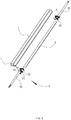
FIG. 1 is a schematic structural view of a waterproof power supply according to an embodiment of the present invention. -
FIG. 2 is an angular exploded view ofFIG. 1 . -
FIG. 3 is a sectional view along a-a direction after removing the power cord at one end of the power supply inFIG. 1 . - Embodiments of the invention are described in detail below, Examples of the embodiments are shown in the appended drawings in which consistently identical or similar labels represent identical or similar elements or elements having the same or similar function. The embodiments described below by reference to the drawings are exemplary and are only used for the interpretation of the invention and cannot be understood to be a limitation of the invention.
- The present application relates to a waterproof power supply including a
housing 1 having apower supply component 2 disposed therein, thehousing 1 is provided with anopening 11. The waterproof power supply also includesend cover 3 which is connected to the opening 11 on thehousing 1. Theend cover 3 and theopening 11 of thehousing 1 can cooperate to form a relatively sealed cavity in the present application, and the sealing of end cover and housing can be realized by injecting colloid into the cavity, and then the whole housing can be sealed for effective waterproof. -
FIG.1-3 shows a structural diagram of the waterproof power supply of the present invention, but it needs to be noted that here is one embodiment structure of the present invention is shown here, but not limited to this structure, other power structures that can achieve the functions and effects described in this application also fall within the scope of protection of this application. - In this embodiment, the
end cover 3 includes two oppositely disposed and connectedbaffles baffles housing 1. - Specifically, in the embodiment, the
baffle 31 on the outer side of theend cover 3 is provided withinjection hole 33 and overflow hole 34.The colloid is injected into the cavity from theinjection hole 33, and the colloid continuously occupies the internal space of the cavity during the injection process, thereby the air in the cavity is discharged from theoverflow hole 34, and the colloid overflows from theoverflow hole 34 after the colloid completely occupies the entire cavity. - In the past, when the power supply housing is encapsulated, it was necessary to vacuum the housing and fill the housing with sealing adhesive. If there is no vacuum inside the housing, the air holes in the sealing adhesive might be formed, and water vapor might enter the housing through the air holes, thus short-circuiting the components in the power supply housing. This kind of waterproof method has high requirements for equipment and low production efficiency.
- In this embodiment, the connectivity principle is skillfully utilized, the injection hole and the overflow hole are arranged on the end cover by taking advantage of the feature that the injection of the colloid into the cavity takes up space and cause the gas in the cavity to be squeezed out, and the gas is discharged from the overflow hole during the injection process, which simplifies the operation of gas exhaust, but has the same good effect.
- In order to further improve the sealing effect, reduce the trouble caused by the poor sealing effect, and at the same time reduce the production cost, simplifying the sealing step, the
housing 1 is integrally formed as shown infigure 2 of the present embodiment. Preferably, thehousing 1 is integrally formed with aluminum alloy, but it can of course be made of other materials. The housing is integrally designed. In this way, the place where the power supply may leak or need to be waterproof, the focus of the previous large area of the housing is reduced to the local area of the open end of the housing, that is, the reduction of the focus of waterproofing. - As shown in
FIG.1-3 , in the embodiment, thehousing 1 has a square cylindrical design, and the openings are located at both ends of the cylinder. Of course, the opening on thehousing 1 may also be one. The other end of the power supply in this structure is directly extended from the other end of the cylinder integral molding by the power cord. - correspondingly, the two
baffles end cover 3 are conductive plates and are connected by other conductive materials such as screws. Thebaffles opening 11 and the side wall of thehousing 1 are combined into a cavity, and only part of the two ends of the cylinder are required to be injected at the time of sealing, and it saves costs. - The
power supply component 2 is a circuit motherboard, which is set along the cylindrical direction, and thebaffle 32 on the inner side of theend cover 3 is connected with one end of the circuit motherboard; theend cover 3 is further provided withpower cord 35, and thepower cord 35 is connected at least to thebaffle 31 on the outer side of theend cover 3. The power cord is electrically connected to the circuit motherboard through the baffle made of the conductive material, and the baffle is in contact with the circuit motherboard face to face, which can effectively guarantee conduction performance, at the same time, this kind of structure can effectively avoid the problem that the connection between the power cord and the motherboard personally before, which is easy to appear the problem of bad contact caused by the virtual welding or the disconnection, and simplify the power structure. - It can be known that the two
baffles end cover 3 can also be integrally formed, and the specific structure is no longer repeat here; the colloid is a waterproof neutral silica gel, which is injected until it reaches IP6 level 8.
Claims (5)
- A waterproof power supply, including:housing (1), the housing (1) is provided with built-in power supply component (2);end cover (3), the end cover (3) is connected to the opening (11) on the housing (1);wherein the end cover (3) and the opening (11) of the housing (1) form a sealed cavity, and the sealing of end cover (3) and housing (1) can be realized by injecting colloid into the cavity, andwherein the end cover (3) includes two oppositely disposed and connected baffles (31, 32), and the cavity is formed by the enclosure of two baffles (31, 32) and the side wall of the housing (1),characterized in thatthe two baffles (31, 32) are conductive plates and are electrically connected;the power supply component (2) is a circuit motherboard, the baffle (32) on the inner side of the end cover (3) is connected with one end of the circuit motherboard;the end cover (3) is further provided with power cord (35), and the power cord (35) is connected at least to the baffle (31) on the outer side of the end cover (3), andthat the two baffles (31, 32) are connected through a conductive connector.
- The waterproof power supply of claim 1, wherein the baffle (31) on the outer side of the end cover (3) is provided with injection hole (33) and overflow hole (34), the colloid is injected into the cavity from the injection hole (33), the air in the cavity is discharged from the overflow hole (34) during the injection process, and the colloid overflows from the overflow hole (34) after the colloid is filled with the cavity.
- The waterproof power supply of claim 1, wherein the housing (1) is integrally formed.
- The waterproof power supply of claim 1, wherein two openings (11) are formed on the housing (1), respectively located at two ends of the housing (1).
- The waterproof power supply of claim 1, wherein the two baffles (31, 32) are integrally formed.
Applications Claiming Priority (1)
| Application Number | Priority Date | Filing Date | Title |
|---|---|---|---|
| CN201810364790.XA CN108463074B (en) | 2018-04-20 | 2018-04-20 | Waterproof power supply |
Publications (2)
| Publication Number | Publication Date |
|---|---|
| EP3557959A1 EP3557959A1 (en) | 2019-10-23 |
| EP3557959B1 true EP3557959B1 (en) | 2020-07-01 |
Family
ID=63235168
Family Applications (1)
| Application Number | Title | Priority Date | Filing Date |
|---|---|---|---|
| EP19170172.1A Active EP3557959B1 (en) | 2018-04-20 | 2019-04-18 | Waterproof power supply |
Country Status (2)
| Country | Link |
|---|---|
| EP (1) | EP3557959B1 (en) |
| CN (1) | CN108463074B (en) |
Families Citing this family (2)
| Publication number | Priority date | Publication date | Assignee | Title |
|---|---|---|---|---|
| CN112804842A (en) * | 2021-01-29 | 2021-05-14 | 赛尔富电子有限公司 | Frictionless waterproof power supply and glue injection process thereof |
| CN114156348B (en) * | 2021-05-14 | 2024-08-27 | 华海通信技术有限公司 | End cover of photoelectric component, photoelectric component and manufacturing method of end cover |
Family Cites Families (8)
| Publication number | Priority date | Publication date | Assignee | Title |
|---|---|---|---|---|
| JP4653777B2 (en) * | 2007-04-13 | 2011-03-16 | 森山産業株式会社 | Waterproof structure at the end of tubular light emitter |
| CN102055303B (en) | 2009-10-27 | 2013-09-11 | 胡建龙 | Waterproof power supply |
| CN103369896B (en) * | 2012-03-28 | 2016-08-17 | 台达电子工业股份有限公司 | External structure of outdoor electronic device |
| CN203313561U (en) * | 2013-06-17 | 2013-11-27 | 扬州大得机电科技有限公司 | Casing sealing structure |
| CN203784891U (en) * | 2014-03-24 | 2014-08-20 | 中山市京港数码科技有限公司 | A waterproof driving power supply |
| DK3177119T3 (en) * | 2015-12-01 | 2019-01-14 | Friwo Geraetebau Gmbh | Waterproof housing, power supply and mounting procedure |
| CN105576156A (en) * | 2016-02-15 | 2016-05-11 | 东莞市云帆电子科技有限公司 | Battery filled with sealant |
| CN208210501U (en) * | 2018-04-20 | 2018-12-07 | 赛尔富电子有限公司 | A kind of waterproof power supply |
-
2018
- 2018-04-20 CN CN201810364790.XA patent/CN108463074B/en active Active
-
2019
- 2019-04-18 EP EP19170172.1A patent/EP3557959B1/en active Active
Non-Patent Citations (1)
| Title |
|---|
| None * |
Also Published As
| Publication number | Publication date |
|---|---|
| EP3557959A1 (en) | 2019-10-23 |
| CN108463074B (en) | 2023-11-21 |
| CN108463074A (en) | 2018-08-28 |
Similar Documents
| Publication | Publication Date | Title |
|---|---|---|
| CN208095026U (en) | A kind of drive motor controller | |
| CN114069118B (en) | Single cells, battery modules and battery packs | |
| JP2025081608A (en) | Electrochemical energy storage device | |
| CN209692624U (en) | An integrated motor inverter assembly | |
| EP3557959A1 (en) | Waterproof power supply | |
| CN219575778U (en) | Battery cover plate assembly and battery | |
| CN117438752A (en) | A square battery, assembly method and electrical equipment | |
| CN113193417A (en) | Controller and electric vehicle | |
| CN217719328U (en) | Explosion-proof type high-voltage damping capacitor | |
| CN208210501U (en) | A kind of waterproof power supply | |
| CN217900885U (en) | Sensor shell | |
| CN216720100U (en) | Single battery, battery module and battery pack | |
| CN214753392U (en) | A capacitor device and installation structure for BSG system | |
| CN215184736U (en) | Controller and electric vehicle | |
| CN213212432U (en) | Aviation waterproof plug shell | |
| CN118659082A (en) | High-capacity battery | |
| CN210101339U (en) | Motor controller for vehicle | |
| CN220209411U (en) | Stitch connection type actuator | |
| CN221447001U (en) | Explosion-proof damping absorption capacitor | |
| CN215988441U (en) | Waterproof corrosion-resistant capacitor structure | |
| CN223582824U (en) | Bus capacitor | |
| CN114582634B (en) | Super capacitor module for starting and stopping automobile | |
| CN220874513U (en) | Filtering magnetic core structure, filter, motor controller and vehicle | |
| CN219395265U (en) | Electric automobile charging assembly control box with IP67 protection level | |
| CN221827998U (en) | Battery cover assembly, battery, battery pack and electrical equipment |
Legal Events
| Date | Code | Title | Description |
|---|---|---|---|
| PUAI | Public reference made under article 153(3) epc to a published international application that has entered the european phase |
Free format text: ORIGINAL CODE: 0009012 |
|
| STAA | Information on the status of an ep patent application or granted ep patent |
Free format text: STATUS: THE APPLICATION HAS BEEN PUBLISHED |
|
| STAA | Information on the status of an ep patent application or granted ep patent |
Free format text: STATUS: REQUEST FOR EXAMINATION WAS MADE |
|
| AK | Designated contracting states |
Kind code of ref document: A1 Designated state(s): AL AT BE BG CH CY CZ DE DK EE ES FI FR GB GR HR HU IE IS IT LI LT LU LV MC MK MT NL NO PL PT RO RS SE SI SK SM TR |
|
| AX | Request for extension of the european patent |
Extension state: BA ME |
|
| 17P | Request for examination filed |
Effective date: 20191010 |
|
| RBV | Designated contracting states (corrected) |
Designated state(s): AL AT BE BG CH CY CZ DE DK EE ES FI FR GB GR HR HU IE IS IT LI LT LU LV MC MK MT NL NO PL PT RO RS SE SI SK SM TR |
|
| GRAP | Despatch of communication of intention to grant a patent |
Free format text: ORIGINAL CODE: EPIDOSNIGR1 |
|
| STAA | Information on the status of an ep patent application or granted ep patent |
Free format text: STATUS: GRANT OF PATENT IS INTENDED |
|
| INTG | Intention to grant announced |
Effective date: 20200310 |
|
| GRAS | Grant fee paid |
Free format text: ORIGINAL CODE: EPIDOSNIGR3 |
|
| GRAA | (expected) grant |
Free format text: ORIGINAL CODE: 0009210 |
|
| STAA | Information on the status of an ep patent application or granted ep patent |
Free format text: STATUS: THE PATENT HAS BEEN GRANTED |
|
| AK | Designated contracting states |
Kind code of ref document: B1 Designated state(s): AL AT BE BG CH CY CZ DE DK EE ES FI FR GB GR HR HU IE IS IT LI LT LU LV MC MK MT NL NO PL PT RO RS SE SI SK SM TR |
|
| REG | Reference to a national code |
Ref country code: CH Ref legal event code: EP Ref country code: AT Ref legal event code: REF Ref document number: 1287411 Country of ref document: AT Kind code of ref document: T Effective date: 20200715 |
|
| REG | Reference to a national code |
Ref country code: IE Ref legal event code: FG4D |
|
| REG | Reference to a national code |
Ref country code: DE Ref legal event code: R096 Ref document number: 602019000218 Country of ref document: DE |
|
| REG | Reference to a national code |
Ref country code: LT Ref legal event code: MG4D |
|
| PG25 | Lapsed in a contracting state [announced via postgrant information from national office to epo] |
Ref country code: BG Free format text: LAPSE BECAUSE OF FAILURE TO SUBMIT A TRANSLATION OF THE DESCRIPTION OR TO PAY THE FEE WITHIN THE PRESCRIBED TIME-LIMIT Effective date: 20201001 |
|
| REG | Reference to a national code |
Ref country code: NL Ref legal event code: MP Effective date: 20200701 |
|
| REG | Reference to a national code |
Ref country code: AT Ref legal event code: MK05 Ref document number: 1287411 Country of ref document: AT Kind code of ref document: T Effective date: 20200701 |
|
| PG25 | Lapsed in a contracting state [announced via postgrant information from national office to epo] |
Ref country code: PT Free format text: LAPSE BECAUSE OF FAILURE TO SUBMIT A TRANSLATION OF THE DESCRIPTION OR TO PAY THE FEE WITHIN THE PRESCRIBED TIME-LIMIT Effective date: 20201102 Ref country code: HR Free format text: LAPSE BECAUSE OF FAILURE TO SUBMIT A TRANSLATION OF THE DESCRIPTION OR TO PAY THE FEE WITHIN THE PRESCRIBED TIME-LIMIT Effective date: 20200701 Ref country code: LT Free format text: LAPSE BECAUSE OF FAILURE TO SUBMIT A TRANSLATION OF THE DESCRIPTION OR TO PAY THE FEE WITHIN THE PRESCRIBED TIME-LIMIT Effective date: 20200701 Ref country code: GR Free format text: LAPSE BECAUSE OF FAILURE TO SUBMIT A TRANSLATION OF THE DESCRIPTION OR TO PAY THE FEE WITHIN THE PRESCRIBED TIME-LIMIT Effective date: 20201002 Ref country code: ES Free format text: LAPSE BECAUSE OF FAILURE TO SUBMIT A TRANSLATION OF THE DESCRIPTION OR TO PAY THE FEE WITHIN THE PRESCRIBED TIME-LIMIT Effective date: 20200701 Ref country code: FI Free format text: LAPSE BECAUSE OF FAILURE TO SUBMIT A TRANSLATION OF THE DESCRIPTION OR TO PAY THE FEE WITHIN THE PRESCRIBED TIME-LIMIT Effective date: 20200701 Ref country code: SE Free format text: LAPSE BECAUSE OF FAILURE TO SUBMIT A TRANSLATION OF THE DESCRIPTION OR TO PAY THE FEE WITHIN THE PRESCRIBED TIME-LIMIT Effective date: 20200701 Ref country code: CZ Free format text: LAPSE BECAUSE OF FAILURE TO SUBMIT A TRANSLATION OF THE DESCRIPTION OR TO PAY THE FEE WITHIN THE PRESCRIBED TIME-LIMIT Effective date: 20200701 Ref country code: NO Free format text: LAPSE BECAUSE OF FAILURE TO SUBMIT A TRANSLATION OF THE DESCRIPTION OR TO PAY THE FEE WITHIN THE PRESCRIBED TIME-LIMIT Effective date: 20201001 Ref country code: AT Free format text: LAPSE BECAUSE OF FAILURE TO SUBMIT A TRANSLATION OF THE DESCRIPTION OR TO PAY THE FEE WITHIN THE PRESCRIBED TIME-LIMIT Effective date: 20200701 |
|
| PG25 | Lapsed in a contracting state [announced via postgrant information from national office to epo] |
Ref country code: PL Free format text: LAPSE BECAUSE OF FAILURE TO SUBMIT A TRANSLATION OF THE DESCRIPTION OR TO PAY THE FEE WITHIN THE PRESCRIBED TIME-LIMIT Effective date: 20200701 Ref country code: RS Free format text: LAPSE BECAUSE OF FAILURE TO SUBMIT A TRANSLATION OF THE DESCRIPTION OR TO PAY THE FEE WITHIN THE PRESCRIBED TIME-LIMIT Effective date: 20200701 Ref country code: LV Free format text: LAPSE BECAUSE OF FAILURE TO SUBMIT A TRANSLATION OF THE DESCRIPTION OR TO PAY THE FEE WITHIN THE PRESCRIBED TIME-LIMIT Effective date: 20200701 Ref country code: IS Free format text: LAPSE BECAUSE OF FAILURE TO SUBMIT A TRANSLATION OF THE DESCRIPTION OR TO PAY THE FEE WITHIN THE PRESCRIBED TIME-LIMIT Effective date: 20201101 |
|
| PG25 | Lapsed in a contracting state [announced via postgrant information from national office to epo] |
Ref country code: NL Free format text: LAPSE BECAUSE OF FAILURE TO SUBMIT A TRANSLATION OF THE DESCRIPTION OR TO PAY THE FEE WITHIN THE PRESCRIBED TIME-LIMIT Effective date: 20200701 |
|
| REG | Reference to a national code |
Ref country code: DE Ref legal event code: R097 Ref document number: 602019000218 Country of ref document: DE |
|
| PG25 | Lapsed in a contracting state [announced via postgrant information from national office to epo] |
Ref country code: IT Free format text: LAPSE BECAUSE OF FAILURE TO SUBMIT A TRANSLATION OF THE DESCRIPTION OR TO PAY THE FEE WITHIN THE PRESCRIBED TIME-LIMIT Effective date: 20200701 Ref country code: SM Free format text: LAPSE BECAUSE OF FAILURE TO SUBMIT A TRANSLATION OF THE DESCRIPTION OR TO PAY THE FEE WITHIN THE PRESCRIBED TIME-LIMIT Effective date: 20200701 Ref country code: DK Free format text: LAPSE BECAUSE OF FAILURE TO SUBMIT A TRANSLATION OF THE DESCRIPTION OR TO PAY THE FEE WITHIN THE PRESCRIBED TIME-LIMIT Effective date: 20200701 Ref country code: RO Free format text: LAPSE BECAUSE OF FAILURE TO SUBMIT A TRANSLATION OF THE DESCRIPTION OR TO PAY THE FEE WITHIN THE PRESCRIBED TIME-LIMIT Effective date: 20200701 Ref country code: EE Free format text: LAPSE BECAUSE OF FAILURE TO SUBMIT A TRANSLATION OF THE DESCRIPTION OR TO PAY THE FEE WITHIN THE PRESCRIBED TIME-LIMIT Effective date: 20200701 |
|
| PLBE | No opposition filed within time limit |
Free format text: ORIGINAL CODE: 0009261 |
|
| STAA | Information on the status of an ep patent application or granted ep patent |
Free format text: STATUS: NO OPPOSITION FILED WITHIN TIME LIMIT |
|
| PG25 | Lapsed in a contracting state [announced via postgrant information from national office to epo] |
Ref country code: AL Free format text: LAPSE BECAUSE OF FAILURE TO SUBMIT A TRANSLATION OF THE DESCRIPTION OR TO PAY THE FEE WITHIN THE PRESCRIBED TIME-LIMIT Effective date: 20200701 |
|
| 26N | No opposition filed |
Effective date: 20210406 |
|
| PG25 | Lapsed in a contracting state [announced via postgrant information from national office to epo] |
Ref country code: SK Free format text: LAPSE BECAUSE OF FAILURE TO SUBMIT A TRANSLATION OF THE DESCRIPTION OR TO PAY THE FEE WITHIN THE PRESCRIBED TIME-LIMIT Effective date: 20200701 |
|
| PG25 | Lapsed in a contracting state [announced via postgrant information from national office to epo] |
Ref country code: SI Free format text: LAPSE BECAUSE OF FAILURE TO SUBMIT A TRANSLATION OF THE DESCRIPTION OR TO PAY THE FEE WITHIN THE PRESCRIBED TIME-LIMIT Effective date: 20200701 |
|
| PG25 | Lapsed in a contracting state [announced via postgrant information from national office to epo] |
Ref country code: MC Free format text: LAPSE BECAUSE OF FAILURE TO SUBMIT A TRANSLATION OF THE DESCRIPTION OR TO PAY THE FEE WITHIN THE PRESCRIBED TIME-LIMIT Effective date: 20200701 |
|
| PG25 | Lapsed in a contracting state [announced via postgrant information from national office to epo] |
Ref country code: LU Free format text: LAPSE BECAUSE OF NON-PAYMENT OF DUE FEES Effective date: 20210418 |
|
| REG | Reference to a national code |
Ref country code: BE Ref legal event code: MM Effective date: 20210430 |
|
| PG25 | Lapsed in a contracting state [announced via postgrant information from national office to epo] |
Ref country code: FR Free format text: LAPSE BECAUSE OF NON-PAYMENT OF DUE FEES Effective date: 20210430 |
|
| PG25 | Lapsed in a contracting state [announced via postgrant information from national office to epo] |
Ref country code: IE Free format text: LAPSE BECAUSE OF NON-PAYMENT OF DUE FEES Effective date: 20210418 |
|
| PG25 | Lapsed in a contracting state [announced via postgrant information from national office to epo] |
Ref country code: IS Free format text: LAPSE BECAUSE OF FAILURE TO SUBMIT A TRANSLATION OF THE DESCRIPTION OR TO PAY THE FEE WITHIN THE PRESCRIBED TIME-LIMIT Effective date: 20201101 |
|
| PG25 | Lapsed in a contracting state [announced via postgrant information from national office to epo] |
Ref country code: BE Free format text: LAPSE BECAUSE OF NON-PAYMENT OF DUE FEES Effective date: 20210430 |
|
| REG | Reference to a national code |
Ref country code: CH Ref legal event code: PL |
|
| PG25 | Lapsed in a contracting state [announced via postgrant information from national office to epo] |
Ref country code: LI Free format text: LAPSE BECAUSE OF NON-PAYMENT OF DUE FEES Effective date: 20220430 Ref country code: CH Free format text: LAPSE BECAUSE OF NON-PAYMENT OF DUE FEES Effective date: 20220430 |
|
| PG25 | Lapsed in a contracting state [announced via postgrant information from national office to epo] |
Ref country code: CY Free format text: LAPSE BECAUSE OF FAILURE TO SUBMIT A TRANSLATION OF THE DESCRIPTION OR TO PAY THE FEE WITHIN THE PRESCRIBED TIME-LIMIT Effective date: 20200701 |
|
| PG25 | Lapsed in a contracting state [announced via postgrant information from national office to epo] |
Ref country code: HU Free format text: LAPSE BECAUSE OF FAILURE TO SUBMIT A TRANSLATION OF THE DESCRIPTION OR TO PAY THE FEE WITHIN THE PRESCRIBED TIME-LIMIT; INVALID AB INITIO Effective date: 20190418 |
|
| GBPC | Gb: european patent ceased through non-payment of renewal fee |
Effective date: 20230418 |
|
| PG25 | Lapsed in a contracting state [announced via postgrant information from national office to epo] |
Ref country code: GB Free format text: LAPSE BECAUSE OF NON-PAYMENT OF DUE FEES Effective date: 20230418 |
|
| PG25 | Lapsed in a contracting state [announced via postgrant information from national office to epo] |
Ref country code: GB Free format text: LAPSE BECAUSE OF NON-PAYMENT OF DUE FEES Effective date: 20230418 |
|
| PG25 | Lapsed in a contracting state [announced via postgrant information from national office to epo] |
Ref country code: MK Free format text: LAPSE BECAUSE OF FAILURE TO SUBMIT A TRANSLATION OF THE DESCRIPTION OR TO PAY THE FEE WITHIN THE PRESCRIBED TIME-LIMIT Effective date: 20200701 |
|
| PG25 | Lapsed in a contracting state [announced via postgrant information from national office to epo] |
Ref country code: TR Free format text: LAPSE BECAUSE OF FAILURE TO SUBMIT A TRANSLATION OF THE DESCRIPTION OR TO PAY THE FEE WITHIN THE PRESCRIBED TIME-LIMIT Effective date: 20200701 |
|
| PG25 | Lapsed in a contracting state [announced via postgrant information from national office to epo] |
Ref country code: MT Free format text: LAPSE BECAUSE OF FAILURE TO SUBMIT A TRANSLATION OF THE DESCRIPTION OR TO PAY THE FEE WITHIN THE PRESCRIBED TIME-LIMIT Effective date: 20200701 |
|
| PGFP | Annual fee paid to national office [announced via postgrant information from national office to epo] |
Ref country code: DE Payment date: 20250430 Year of fee payment: 7 |