EP3557816A1 - Self-diagnosis method for communication protocol of security-level instrumentation and control system of nuclear power plant - Google Patents
Self-diagnosis method for communication protocol of security-level instrumentation and control system of nuclear power plant Download PDFInfo
- Publication number
- EP3557816A1 EP3557816A1 EP17894461.7A EP17894461A EP3557816A1 EP 3557816 A1 EP3557816 A1 EP 3557816A1 EP 17894461 A EP17894461 A EP 17894461A EP 3557816 A1 EP3557816 A1 EP 3557816A1
- Authority
- EP
- European Patent Office
- Prior art keywords
- data
- data frame
- diagnosis
- self
- control system
- Prior art date
- Legal status (The legal status is an assumption and is not a legal conclusion. Google has not performed a legal analysis and makes no representation as to the accuracy of the status listed.)
- Granted
Links
Images


Classifications
-
- H—ELECTRICITY
- H04—ELECTRIC COMMUNICATION TECHNIQUE
- H04L—TRANSMISSION OF DIGITAL INFORMATION, e.g. TELEGRAPHIC COMMUNICATION
- H04L41/00—Arrangements for maintenance, administration or management of data switching networks, e.g. of packet switching networks
- H04L41/06—Management of faults, events, alarms or notifications
- H04L41/0681—Configuration of triggering conditions
-
- H—ELECTRICITY
- H04—ELECTRIC COMMUNICATION TECHNIQUE
- H04L—TRANSMISSION OF DIGITAL INFORMATION, e.g. TELEGRAPHIC COMMUNICATION
- H04L41/00—Arrangements for maintenance, administration or management of data switching networks, e.g. of packet switching networks
-
- Y—GENERAL TAGGING OF NEW TECHNOLOGICAL DEVELOPMENTS; GENERAL TAGGING OF CROSS-SECTIONAL TECHNOLOGIES SPANNING OVER SEVERAL SECTIONS OF THE IPC; TECHNICAL SUBJECTS COVERED BY FORMER USPC CROSS-REFERENCE ART COLLECTIONS [XRACs] AND DIGESTS
- Y04—INFORMATION OR COMMUNICATION TECHNOLOGIES HAVING AN IMPACT ON OTHER TECHNOLOGY AREAS
- Y04S—SYSTEMS INTEGRATING TECHNOLOGIES RELATED TO POWER NETWORK OPERATION, COMMUNICATION OR INFORMATION TECHNOLOGIES FOR IMPROVING THE ELECTRICAL POWER GENERATION, TRANSMISSION, DISTRIBUTION, MANAGEMENT OR USAGE, i.e. SMART GRIDS
- Y04S40/00—Systems for electrical power generation, transmission, distribution or end-user application management characterised by the use of communication or information technologies, or communication or information technology specific aspects supporting them
Definitions
- the invention relates to a diagnosis method for a communication protocol of a safety instrumentation and control system of a nuclear plant, in particular to a diagnosis method for a point-to-point communication protocol.
- a safety instrumentation and control system the "neural center" of a nuclear plant, is the most important means to ensure the safe and reliable operation of a nuclear plant.
- TXS, Meltac-N, Tricon and Common-Q are the main safety instrumentation and control systems for nuclear plants.
- a SINEC L2 communication network based on Profibus is adopted for communication among redundant channels in the system; for Meltac-N, point-to-point communication based on RS-485 is adopted for communication between control stations in the system; for Tricon, a bus communication based on RS-232/485 is adopted in the system internal communication; for Common-Q, transmission of redundant inter-channel voting logic signals within the system employs RS-232 based HSL point-to-point communication.
- RS-232/485 is the main serial communication interface in an industrial control network.
- a typical structure of a safety instrumentation and control system of a nuclear plant is shown in Figure 1 , logical coincidence operation needs to be carried out among processing units (RPC) in Figure 1 , and direct data interaction is inevitable.
- Self-diagnosis refers to the technology by which the system self-detects and processes the fault or failure event by setting a diagnosis function
- the core of self-diagnosis technology is the diagnosis measure and the fault processing after diagnosis.
- a typical self-diagnostic process is as follows: after a fault occurs in the operation process, the system should identify the abnormal condition of the system through hardware or software, quickly report the abnormal information, start a processing mechanism, enter a degraded operation or fault safety state, and the system can restore the normal operation state only until the fault is eliminated.
- CN103457791A discloses a self-diagnosis method for an intelligent substation network sampling and control link, which can timely discover and troubleshoot various network faults of network operation, and manage and record the network fault information, so as to further ensure the reliability and safety of network sampling and network control in substation applications, and improve the intelligent level of the substation.
- CN102984097A discloses transceiver self-diagnostics for balancing electromagnetic interference reduction within a channel, which enables communication links supporting differential signaling to carry common mode signals, and any detected selective operation such as appropriate processing of signal energy corresponding to the differential signal energy to provide measurements corresponding to electromagnetic compatibility (EMC) of the communication link.
- EMC electromagnetic compatibility
- the invention provides a self-diagnosis method for a communication protocol of a safety instrumentation and control system of a nuclear plant, which can effectively determine network communication errors.
- the invention provides a self-diagnosis method for a communication protocol of a safety instrumentation and control system of a nuclear plant, on the basis of a point-to-point network protocol composed of an application layer, a data link layer and a physical layer, wherein the network protocol has a constant network data volume, the interface mode is a full-duplex asynchronous transmission mode, the transmission medium is a multi-film optical fiber, the operation periods of a sender and a receiver range from 8ms to 20ms, and the application layer data frame format comprises a destination MAC, a source MAC, an application mode, TICK, a message serial number, a message total length, a frame valid data length, a message frame number, a serial page of the message frame, a retransmission bit, a reserved area, upper layer data and a CRC check code, wherein a destination MAC, a source MAC, a frame valid data length and upper layer data are obtained through a configuration tool, and the length of a data frame of an application layer range
- the self-diagnosis method for the communication protocol of the safety instrumentation and control system of a nuclear plant of the invention realizes full coverage of diagnosis of eight network errors; whether the upper layer data quality bit is valid or not is accurately determined, so that erroneous data cannot be misused; and a reasonable frequency tolerance threshold for the diagnosed network fault is set, so that the stability of the system is ensured (repeated state jump caused by occasional errors is avoided), and the network fault can be reported instantly when confirmed.
- the present method minimizes the possibility of mistakes in determination, and can effectively ensure the point-to-point communication quality of the safety instrumentation and control system of a nuclear plant.
- the invention relates to a self-diagnosis implementation method based on a communication method related to the applicant's patent ZL200910238712.6 "Communication Method based on Inter-Column Safety Communication Network Protocol of Reactor Protection System".
- the patent ZL200910238712.6 relates to a safety network protocol for inter-column communication of a system, in particular to a communication method based on an inter-column safety communication network protocol of a reactor protection system.
- the communication protocol is suitable for a nuclear power control system, however, according to the self-diagnosis requirements of IEC6178-3, IEC60880 and IEC61508 on a safety network, a full diagnostic coverage of eight network errors including data collapse, accidental retransmission, wrong sequence, loss, delay timeout, invalid insertion, masquerading messages and error addressing is needed, and the requirement of a network residual rate has also to be met.
- Network residual rate is an important index to measure the safety level of a safety network.
- Hamming Distance the number of bits taking different values among corresponding bits of two codewords is called the Hamming distance of the two codewords. In an active code set, the minimum value of the Hamming distance of any two codewords is referred to as the Hamming distance of the code set. Examples are as follows: 10101 and 00110 have their first bit, fourth bit and fifth bit different in sequence from the first, so the Hamming distance is 3.
- the self-diagnosis method of the present invention relates to using asynchronous communication by the receiver and the sender, and the receiver cannot send a response frame to the sender.
- the network equipment can only read the network data frame in a regular inquiry mode when sending, receiving and reading the network data, and cannot read the network data by using an interruption mechanism.
- the data frame structure is shown in the following table, wherein the data frame structure includes a destination address, a source address, an application layer protocol number, an application layer data part and a CRC check code. Where the application layer protocol number is constantly "OXAABB" in this embodiment. Destination MAC Address Source MAC Address Application Layer Protocol No. Application Layer Data CRC Checksum
- the total length of an application layer data frame is defined as 1000 bytes, and the data frame of the application layer is shown in the following table: function code application mode TICK value message serial number length of data length of valid data in this group total number of groups serial number of the group retransmission bit reserved area upper layer data CRC check code
- the function code specifically identifies a data pattern; the application mode is specified according to the protocol, and has a fixed value of 3; the TICK value is increased by 1 every period, namely the number of periods; the message serial number is namely the serial number of the message sent in the period, and this field is strongly correlated with the retransmission bit, and when the serial number is 1, it indicates that the data frame is initially transmitted in the period, and the retransmission bit is 0; when the serial number is 2, it indicates that a data frame is retransmitted in the period, and the retransmission bit 1; the length of message name represents the length of the whole data frame, wherein the starting position is a destination MAC address, and the ending position is a CRC check code; the length of valid data in this group represents the valid data length of the upper layer data; the total number of groups represents the total packet number of the data in this group; the serial number of the group represents the packet No.
- the retransmission bit 0 represents that a data frame is initially transmitted in the period; 1 represents a data frame is retransmitted in the period. Except a message serial number, a retransmission bit and a CRC check code, other fields of the two packets of data frames are completely consistent; the reserved area has a value of 0 and is an extension field of the field; the upper layer data represents a command that the system collects or needs to send; the CRC check code: when the retransmission bit is 0, the used CRC check value is 0x04C11DB7; when the retransmission bit is 1, the used CRC check value is 0xBA0DC66B.
- the sender acquires an operation period of 10ms for itself, a local MAC ⁇ 0x01, 0x05, 0x03, 0x07, 0x0a ⁇ , a destination MAC ⁇ 0x02, 0x03, 0x05, 0x0a, 0x0b ⁇ in the initialization phase
- the receiver acquires an operation period of 10ms for itself, a local MAC ⁇ 0x02, 0x03, 0x05, 0x0a, 0x0b ⁇ , and a destination MAC ⁇ 0x01, 0x05, 0x03, 0x07, 0x0a ⁇ in the initialization phase.
- the time window for receiving data frames set by the receiver is 20 milliseconds, and the tolerance threshold value for times of diagnostic abnormalities is 3.
- the specific diagnosis method comprises the steps of:
- the application layer protocol number is fixed to "OXAABB" and the application mode is fixed to a value of 3.
- the sender acquires an operation period of 8ms for itself, a local MAC ⁇ 0x01, 0x05, 0x03, 0x07, 0x0a ⁇ , a destination MAC ⁇ 0x02, 0x03, 0x05, 0x0a, 0x0b ⁇ in the initialization phase
- the receiver acquires an operation period of 8ms for itself, a local MAC ⁇ 0x02, 0x03, 0x05, 0x0a, 0x0b ⁇ , and a destination MAC ⁇ 0x01, 0x05, 0x03, 0x07, 0x0a ⁇ in the initialization phase.
- the time window for receiving data frames set by the receiver is 32ms, and the tolerance threshold value for times of diagnostic abnormalities is 5.
- the specific diagnosis method comprises the steps of:
- the application layer protocol number is fixed to "OXAABB" and the application mode is fixed to a value of 3.
- the sender acquires an operation period of 20ms for itself, a local MAC ⁇ 0x01, 0x05, 0x03, 0x07, 0x0a ⁇ , a destination MAC ⁇ 0x02, 0x03, 0x05, 0x0a, 0x0b ⁇ in the initialization phase
- the receiver acquires an operation period of 20ms for itself, a local MAC ⁇ 0x02, 0x03, 0x05, 0x0a, 0x0b ⁇ , and a destination MAC ⁇ 0x01, 0x05, 0x03, 0x07, 0x0a ⁇ in the initialization phase.
- the time window for receiving data frames set by the receiver is 60ms, and the tolerance threshold value for times of diagnostic abnormalities is 2.
- the specific diagnosis method comprises the steps of:
- SIL3 Safety Integrity Level
- a safety network for a nuclear power plant has to ensure a residual error rate being less than 10-9.
- the self-diagnosis method of the present invention can correctly diagnose eight transmission errors of the network, and the network residual error rate meets the SIL3 requirement of the level standard.
Landscapes
- Engineering & Computer Science (AREA)
- Computer Networks & Wireless Communication (AREA)
- Signal Processing (AREA)
- Detection And Prevention Of Errors In Transmission (AREA)
- Maintenance And Management Of Digital Transmission (AREA)
Abstract
Description
- The invention relates to a diagnosis method for a communication protocol of a safety instrumentation and control system of a nuclear plant, in particular to a diagnosis method for a point-to-point communication protocol.
- A safety instrumentation and control system, the "neural center" of a nuclear plant, is the most important means to ensure the safe and reliable operation of a nuclear plant. In foreign countries, TXS, Meltac-N, Tricon and Common-Q are the main safety instrumentation and control systems for nuclear plants. For TXS, a SINEC L2 communication network based on Profibus is adopted for communication among redundant channels in the system; for Meltac-N, point-to-point communication based on RS-485 is adopted for communication between control stations in the system; for Tricon, a bus communication based on RS-232/485 is adopted in the system internal communication; for Common-Q, transmission of redundant inter-channel voting logic signals within the system employs RS-232 based HSL point-to-point communication. RS-232/485 is the main serial communication interface in an industrial control network. A typical structure of a safety instrumentation and control system of a nuclear plant is shown in
Figure 1 , logical coincidence operation needs to be carried out among processing units (RPC) inFigure 1 , and direct data interaction is inevitable. This kind of communication only involves two processing units, with a small amount of data but high requirements on the reliability, real-time and security of data communication. The dotted lines inFigure 1 indicate the point-to-point communication network. Due to the occasional fault of the hardware components and bugs of the software itself, the following eight communication errors can occur, which are data crash, accidental retransmission, erroneous sequence, loss, delay timeout, invalid insertion, camouflage messages and erroneous addressing. If the eight network errors are not diagnosed, a misuse of the erroneous network data may happen, and the safety and stability of the safety instrumentation and control system of the whole nuclear plant are put in danger consequently, or even worse, an accidental shutdown of the nuclear plant can be caused, leading to inestimable property loss and personal safety accidents. - Self-diagnosis refers to the technology by which the system self-detects and processes the fault or failure event by setting a diagnosis function, and the core of self-diagnosis technology is the diagnosis measure and the fault processing after diagnosis. A typical self-diagnostic process is as follows: after a fault occurs in the operation process, the system should identify the abnormal condition of the system through hardware or software, quickly report the abnormal information, start a processing mechanism, enter a degraded operation or fault safety state, and the system can restore the normal operation state only until the fault is eliminated.
- For example,
CN103457791A discloses a self-diagnosis method for an intelligent substation network sampling and control link, which can timely discover and troubleshoot various network faults of network operation, and manage and record the network fault information, so as to further ensure the reliability and safety of network sampling and network control in substation applications, and improve the intelligent level of the substation. -
CN102984097A discloses transceiver self-diagnostics for balancing electromagnetic interference reduction within a channel, which enables communication links supporting differential signaling to carry common mode signals, and any detected selective operation such as appropriate processing of signal energy corresponding to the differential signal energy to provide measurements corresponding to electromagnetic compatibility (EMC) of the communication link. - At present, the prior art about network self-diagnosis technology falls all within those aiming at an industrial standard control network, being not suitable for a point-to-point network communication protocol in an existing nuclear plant safety instrumentation and control system.
- Aiming at the defects in the prior art, the invention provides a self-diagnosis method for a communication protocol of a safety instrumentation and control system of a nuclear plant, which can effectively determine network communication errors.
- The invention provides a self-diagnosis method for a communication protocol of a safety instrumentation and control system of a nuclear plant, on the basis of a point-to-point network protocol composed of an application layer, a data link layer and a physical layer, wherein the network protocol has a constant network data volume, the interface mode is a full-duplex asynchronous transmission mode, the transmission medium is a multi-film optical fiber, the operation periods of a sender and a receiver range from 8ms to 20ms, and the application layer data frame format comprises a destination MAC, a source MAC, an application mode, TICK, a message serial number, a message total length, a frame valid data length, a message frame number, a serial page of the message frame, a retransmission bit, a reserved area, upper layer data and a CRC check code, wherein a destination MAC, a source MAC, a frame valid data length and upper layer data are obtained through a configuration tool, and the length of a data frame of an application layer ranges from 256 bytes to 1500 bytes; The data structure of the upper layer data comprises a data value and a quality bit. The self-diagnosis method specifically comprises the steps of:
-
step 1, acquiring a destination MAC, a source MAC and upper layer data by the sender, and packaging and sending the acquired upper layer data in a frame format, wherein the retransmission bit of a initially transmitted data frame is set to be 0, and the retransmission bit of a retransmitted data frame is set to be 1; - step 2, proceeding to step 6 if the receiver does not receive the data frame; if the receiver receives the data frame sent by the sender, checking the destination MAC and the source MAC of the data frame for diagnosing errors in addressing, recording the reason if the diagnosis result is abnormal, and proceeding to the step 7; and proceeding to the step 3 if the diagnosis result is normal;
- step 3, determining a data frame TICK and a message serial number, determining whether four network errors such as retransmission, erroneous sequence, loss and invalid insertion occur or not by checking the TICK value and the value of the message serial number, recording the reason if the diagnosis result is abnormal, and proceeding to the step ; and proceeding to the step 4 if the diagnosis result is normal;
- step 4, checking and diagnosing data collapse errors by using a data frame CRC check code, recording the reason if the diagnosis result is abnormal, proceeding to the step 7, comparing upper layer data in the retransmitted data frame, if the diagnosis results are inconsistent, regarding it as the data collapse, recording the abnormal reason, proceeding to the step 7; and proceeding to the step 5 if the diagnosis result is normal;
- step 5, checking a data frame application mode and an application layer protocol number, if the data frame application mode and the application layer protocol number are not preset values, diagnosing it as a camouflage message, recording the abnormal reason, proceeding to the step 7; and proceeding to the step 8 if the diagnosis result is normal;
- step 6, when the receiver does not receive the data frame while exceeding a set time window for receiving the data frame, diagnosing it as delay overtime, recording the abnormal reason and proceeding to the step 7; and if the set time window of the received data frame is not exceeded, maintaining the current state and recording the time when the data frame is not received, wherein the time window of the received data frame set by the receiver ranges from 2 to 4 times of the maximum period of the sender and the receiver;
- step 7, with the number of times of abnormities diagnosed increased by 1, if the number does not reach the tolerance threshold value, keeping the state unchanged, otherwise, carrying out fault processing of:
- 1) setting the quality bit of the upper layer data of the received data frame to be invalid; and
- 2) exterior reminder: using a dot matrix to display the faults; and
- step 8, resetting the number of times of abnormities diagnosed, and performing fault recovery processing of:
- 1) setting the quality bit of the upper layer data of the received data frame to be valid; and
- 2) exterior reminder: a dot matrix not displaying any information represents a normal result of network diagnosis.
- Compared with the prior art, the self-diagnosis method for the communication protocol of the safety instrumentation and control system of a nuclear plant of the invention realizes full coverage of diagnosis of eight network errors; whether the upper layer data quality bit is valid or not is accurately determined, so that erroneous data cannot be misused; and a reasonable frequency tolerance threshold for the diagnosed network fault is set, so that the stability of the system is ensured (repeated state jump caused by occasional errors is avoided), and the network fault can be reported instantly when confirmed. The present method minimizes the possibility of mistakes in determination, and can effectively ensure the point-to-point communication quality of the safety instrumentation and control system of a nuclear plant.
-
-
Figure 1 is a schematic diagram of a typical nuclear plant safety instrumentation and control system; -
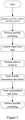
Figure 2 is a block diagram of the sending process of the self-diagnosis method for the communication protocol of the safety instrumentation and control system of a nuclear plant according to the present invention; and -
Figure 3 is a block diagram of the process for receiving data diagnosis of the self-diagnosis method for the communication protocol of the safety instrumentation and control system of a nuclear plant according to the present invention. - The self-diagnosis method for the communication protocol of the safety instrumentation and control system of a nuclear plant is further described with reference to the drawings.
- The invention relates to a self-diagnosis implementation method based on a communication method related to the applicant's patent ZL200910238712.6 "Communication Method based on Inter-Column Safety Communication Network Protocol of Reactor Protection System". The patent ZL200910238712.6 relates to a safety network protocol for inter-column communication of a system, in particular to a communication method based on an inter-column safety communication network protocol of a reactor protection system. The communication protocol is suitable for a nuclear power control system, however, according to the self-diagnosis requirements of IEC6178-3, IEC60880 and IEC61508 on a safety network, a full diagnostic coverage of eight network errors including data collapse, accidental retransmission, wrong sequence, loss, delay timeout, invalid insertion, masquerading messages and error addressing is needed, and the requirement of a network residual rate has also to be met. Network residual rate is an important index to measure the safety level of a safety network. In IEC61784-3, there is a clear formula for calculating the network residual rate, so that the residual rate of the designed network protocol can be quantitatively evaluated, and the formula is as follows:

Symbols Definitions ΔSLPe Safety layer residual error rate (h-1) at a certain bit transmission error rate Pe Bit error rate of the transmission medium, typically being 10-2 without better data support RSLPe Residual error rate of a single safety message V Maximum number of safety messages per hour m Maximum number of message recipients allowed in a single safety function - The residual error rate RSL of a single safety message (Pe) is determined by the selected CRC checking process, and the calculation formula of the residual error rate of the message subjected to CRC checking is as follows:

Symbols Meanings r Length of an additional CRC check string n Length of a transmission data message dmin Minimum Hamming Distance - Hamming Distance: the number of bits taking different values among corresponding bits of two codewords is called the Hamming distance of the two codewords. In an active code set, the minimum value of the Hamming distance of any two codewords is referred to as the Hamming distance of the code set. Examples are as follows: 10101 and 00110 have their first bit, fourth bit and fifth bit different in sequence from the first, so the Hamming distance is 3.
- The self-diagnosis method of the present invention relates to using asynchronous communication by the receiver and the sender, and the receiver cannot send a response frame to the sender. The network equipment can only read the network data frame in a regular inquiry mode when sending, receiving and reading the network data, and cannot read the network data by using an interruption mechanism. The data frame structure is shown in the following table, wherein the data frame structure includes a destination address, a source address, an application layer protocol number, an application layer data part and a CRC check code. Where the application layer protocol number is constantly "OXAABB" in this embodiment.
Destination MAC Address Source MAC Address Application Layer Protocol No. Application Layer Data CRC Checksum - The total length of an application layer data frame is defined as 1000 bytes, and the data frame of the application layer is shown in the following table:
function code application mode TICK value message serial number length of data length of valid data in this group total number of groups serial number of the group retransmission bit reserved area upper layer data CRC check code - Wherein the function code specifically identifies a data pattern;
the application mode is specified according to the protocol, and has a fixed value of 3;
the TICK value is increased by 1 every period, namely the number of periods;
the message serial number is namely the serial number of the message sent in the period, and this field is strongly correlated with the retransmission bit, and when the serial number is 1, it indicates that the data frame is initially transmitted in the period, and the retransmission bit is 0; when the serial number is 2, it indicates that a data frame is retransmitted in the period, and theretransmission bit 1;
the length of message name represents the length of the whole data frame, wherein the starting position is a destination MAC address, and the ending position is a CRC check code;
the length of valid data in this group represents the valid data length of the upper layer data;
the total number of groups represents the total packet number of the data in this group;
the serial number of the group represents the packet No. of the data in the group;
the retransmission bit: 0 represents that a data frame is initially transmitted in the period; 1 represents a data frame is retransmitted in the period. Except a message serial number, a retransmission bit and a CRC check code, other fields of the two packets of data frames are completely consistent;
the reserved area has a value of 0 and is an extension field of the field;
the upper layer data represents a command that the system collects or needs to send;
the CRC check code: when the retransmission bit is 0, the used CRC check value is 0x04C11DB7; when the retransmission bit is 1, the used CRC check value is 0xBA0DC66B. - In the embodiment, the sender acquires an operation period of 10ms for itself, a local MAC {0x01, 0x05, 0x03, 0x07, 0x0a}, a destination MAC {0x02, 0x03, 0x05, 0x0a, 0x0b} in the initialization phase, the receiver acquires an operation period of 10ms for itself, a local MAC {0x02, 0x03, 0x05, 0x0a, 0x0b}, and a destination MAC {0x01, 0x05, 0x03, 0x07, 0x0a} in the initialization phase. The time window for receiving data frames set by the receiver is 20 milliseconds, and the tolerance threshold value for times of diagnostic abnormalities is 3. The specific diagnosis method comprises the steps of:
-
step 1, after a sender enters a cycle period, as shown infigure 2 , periodically acquiring upper layer data and packaging the upper layer data in the protocol format, wherein the TICK value is the number of cycle periods and starts from 0; for the initially transmitted data frame, the message serial number being 0, the retransmission bit being 0, and the CRC check value being 0x04C11DB7; for a retransmitted data frame, the message serial number being 1, the retransmission bit being 1, and the CRC check value being 0xBA0DC66B; - step 2, after the receiver enters a cycle period, as shown in
figure 3 , starting to carry out a periodic diagnosis on the received data frame; if the receiver does not receive the data frame in the current period, proceeding to the step 6; if the receiving party receives the data frame sent by the sender, checking whether the destination MAC of the data frame is {0x02, 0x03, 0x05, 0x0a, 0x0b}, whether the source MAC is {0x01, 0x05, 0x03, 0x07, 0x0a}, diagnosing as erroneous addressing if the data frame is checked as abnormal, recording the reason when the diagnostic result is abnormal, proceeding to the step 7; and proceeding to the step 3 when the check result is normal; - step 3, determining whether four network errors such as retransmission, erroneous sequence, loss and invalid insertion occur or not by diagnosing the TICK, the message serial number and the retransmission bit of data frames, wherein the specific method is as follows:
- in the case that the last data frame has a TICK value being OX5A, a message serial number being 1, and a retransmission bit being 0, and the received data frame this time has a TICK value being OX5B, a message serial number being 1, and a retransmission bit being 0, it can be diagnosed as data frame loss;
- in the case that the last data frame has a TICK value being OX5A, a message serial number being 1, and a retransmission bit being 0, and the received data frame this time has a TICK value being OX5A, a message serial number being 1, and a retransmission bit being 0, it can be diagnosed as retransmission;
- in the case that the last data frame has a TICK value being OX5A, a message serial number being 1, and a retransmission bit being 0, and the received data frame this time has a TICK value being OX50, a message serial number being 1, and a retransmission bit being 0, it can be diagnosed as erroneous sequence;
- in the case that the last data frame has a TICK value being OX5A, a message serial number being 1, and a retransmission bit being 0, and the received data frame this time has a TICK value being OX3C, a message serial number being 9, and a retransmission bit being 0, it can be diagnosed as invalid insertion; and
- in the case that the last data frame has a TICK value being OX5A, a message serial number being 0, and a retransmission bit being 0, and the received data frame this time has a TICK value being OX5A, a message serial number being 2, and a retransmission bit being 1, it can be diagnosed as normal;
- according to the above diagnostic information, recording the abnormal reason when the abnormality is diagnosed, proceeding to the step 7, and proceeding to the step 4 when the check result is normal;
- step 4, performing respective CRC checks on the initially transmitted data frame and the retransmitted date frame, and performing a binary comparison on upper-layer data of the two packets of data frames if the checks are successful; if the upper layer data of the two packet data frames are compared to be consistent, diagnosing it as normal, proceeding to the step 5, otherwise, diagnosing it as data collapse, and proceeding to the step 7;
- step 5, checking whether the application mode and the application layer protocol number of the data frame are preset values or not, namely checking whether the application mode is equal to 3 or not, whether the application layer protocol number is equal to 0XAABB or not, if not, diagnosing as a camouflage message, proceeding to the step 7, otherwise, diagnosing as a normal message, and proceeding to the step 8;
- step 6, if no data frame is received in the period, when the accumulated time during which no data frame is received exceeds 20ms, diagnosing as delay timeout, and proceeding to the step 7; otherwise, keeping the current state and recording the time during which no data frame is received, and proceeding to the next period for diagnosis;
- step 7, with the number of times of abnormities diagnosed increased by 1, if the number does not reach the tolerance threshold value, keeping the state unchanged, otherwise, carrying out fault processing of:
- 1) setting the quality bit of the upper layer data of the received data frame to be 0X2C, the 0X2C representing a quality bit set for the receiver, facilitating searching and positioning;
- 2) exterior reminder: turning off a "RUN" light representing normal communication, displaying a specific reason of a fault by using a dot matrix, displaying "W001" to indicate that a data collapse is diagnosed, displaying "W002" to indicate an accidental data retransmission is diagnosed, displaying "W003" to indicate that an erroneous sequence is diagnosed, displaying "W004" to indicate that a data loss is diagnosed, displaying "W005" to indicate a delay overtime is diagnosed; and displaying "W006" to indicate that an invalid insertion is diagnosed, displaying "W007" to indicate a disguised message is diagnosed and displaying "W008" to indicate an erroneous addressing is diagnosed;
and after fault processing is finished, proceeding to the next period for diagnosis;
- step 8, resetting the number of times of abnormities diagnosed, and performing fault recovery processing of:
- 1) setting the quality bit of the upper layer data of the received data frame to be valid, i.e., setting the quality bit of the upper layer data to be 0; and
- 2) exterior reminder: turning on the "RUN" light representing normal communication, a dot matrix not displaying any information represents a good result of network diagnosis;
- In this embodiment, the application layer protocol number is fixed to "OXAABB" and the application mode is fixed to a value of 3. The sender acquires an operation period of 8ms for itself, a local MAC {0x01, 0x05, 0x03, 0x07, 0x0a}, a destination MAC {0x02, 0x03, 0x05, 0x0a, 0x0b} in the initialization phase, the receiver acquires an operation period of 8ms for itself, a local MAC {0x02, 0x03, 0x05, 0x0a, 0x0b}, and a destination MAC {0x01, 0x05, 0x03, 0x07, 0x0a} in the initialization phase. The time window for receiving data frames set by the receiver is 32ms, and the tolerance threshold value for times of diagnostic abnormalities is 5. The specific diagnosis method comprises the steps of:
-
step 1, after a sender enters a cycle period, as shown infigure 2 , periodically acquiring upper layer data and packaging the upper layer data in the protocol format, wherein the TICK value is the number of cycle periods and starts from 0; for the initially transmitted data frame, the message serial number being 0, the retransmission bit being 0, and the CRC check value being 0x04C11DB7; for a retransmitted data frame, the message serial number being 1, the retransmission bit being 1, and the CRC check value being 0xBA0DC66B; - step 2, after the receiver enters a cycle period, as shown in
figure 3 , starting to carry out a periodic diagnosis on the received data frame; if the receiver does not receive the data frame in the current period, proceeding to the step 6; if the receiving party receives the data frame sent by the sender, checking whether the destination MAC of the data frame is {0x02, 0x03, 0x05, 0x0a, 0x0b}, whether the source MAC is {0x01, 0x05, 0x03, 0x07, 0x0a}, diagnosing as erroneous addressing if the data frame is checked as abnormal, recording the reason when the diagnostic result is abnormal, proceeding to the step 7; and proceeding to the step 3 when the check result is normal; - step 3, determining whether four network errors such as retransmission, erroneous sequence, loss and invalid insertion occur or not by diagnosing the TICK, the message serial number and the retransmission bit of data frames, wherein the specific method is as follows:
- in the case that the last data frame has a TICK value being OX5A, a message serial number being 1, and a retransmission bit being 0, and the received data frame this time has a TICK value being OX5B, a message serial number being 1, and a retransmission bit being 0, it can be diagnosed as data frame loss;
- in the case that the last data frame has a TICK value being OX5A, a message serial number being 1, and a retransmission bit being 0, and the received data frame this time has a TICK value being OX5A, a message serial number being 1, and a retransmission bit being 0, it can be diagnosed as retransmission;
- in the case that the last data frame has a TICK value being OX5A, a message serial number being 1, and a retransmission bit being 0, and the received data frame this time has a TICK value being OX50, a message serial number being 1, and a retransmission bit being 0, it can be diagnosed as erroneous sequence;
- in the case that the last data frame has a TICK value being OX5A, a message serial number being 1, and a retransmission bit being 0, and the received data frame this time has a TICK value being OX3C, a message serial number being 9, and a retransmission bit being 0, it can be diagnosed as invalid insertion; and
- in the case that the last data frame has a TICK value being OX5A, a message serial number being 0, and a retransmission bit being 0, and the received data frame this time has a TICK value being OX5A, a message serial number being 2, and a retransmission bit being 1, it can be diagnosed as normal;
- according to the above diagnostic information, recording the abnormal reason when the abnormality is diagnosed, proceeding to the step 7, and proceeding to the step 4 when the check result is normal;
- step 4, performing respective CRC checks on the initially transmitted data frame and the retransmitted date frame, and performing a binary comparison on upper-layer data of the two packets of data frames if the checks are successful; if the upper layer data of the two packet data frames are compared to be consistent, diagnosing it as normal, proceeding to the step 5, otherwise, diagnosing it as data collapse, and proceeding to the step 7;
- step 5, checking whether the application mode and the application layer protocol number of the data frame are preset values or not, namely checking whether the application mode is equal to 3 or not, whether the application layer protocol number is equal to OXAABB or not, if not, diagnosing as a camouflage message, proceeding to the step 7, otherwise, diagnosing as a normal message, and proceeding to the step 8;
- step 6, if no data frame is received in the period, when the accumulated time during which no data frame is received exceeds 32ms, diagnosing as delay timeout, and proceeding to the step 7; otherwise, keeping the current state and recording the time during which no data frame is received, and proceeding to the next period for diagnosis;
- step 7, with the number of times of abnormities diagnosed increased by 1, if the number does not reach the tolerance threshold value 5, keeping the state unchanged, otherwise, carrying out fault processing of:
- 1) setting the quality bit of the upper layer data of the received data frame to be 0X2C, the 0X2C representing a quality bit set for the receiver, facilitating searching and positioning;
- 2) exterior reminder: turning off a "RUN" light representing normal communication, displaying a specific reason of a fault by using a dot matrix, displaying "W00a" to indicate that a data collapse is diagnosed, displaying "W00b" to indicate an accidental data retransmission is diagnosed, displaying "W00c" to indicate that an erroneous sequence is diagnosed, displaying "WOOd" to indicate that a data loss is diagnosed, displaying "W00e" to indicate a delay overtime is diagnosed; and displaying "W00f" to indicate that an invalid insertion is diagnosed, displaying "W00g" to indicate a disguised message is diagnosed and displaying "W00h" to indicate an erroneous addressing is diagnosed;
and after fault processing is finished, proceeding to the next period for diagnosis;
- step 8, resetting the number of times of abnormities diagnosed, and performing fault recovery processing of:
- 1) setting the quality bit of the upper layer data of the received data frame to be valid, i.e., setting the quality bit of the upper layer data to be 0; and
- 2) exterior reminder: turning on the "RUN" light representing normal communication, a dot matrix not displaying any information represents a good result of network diagnosis;
- In this embodiment, the application layer protocol number is fixed to "OXAABB" and the application mode is fixed to a value of 3. The sender acquires an operation period of 20ms for itself, a local MAC {0x01, 0x05, 0x03, 0x07, 0x0a}, a destination MAC {0x02, 0x03, 0x05, 0x0a, 0x0b} in the initialization phase, the receiver acquires an operation period of 20ms for itself, a local MAC {0x02, 0x03, 0x05, 0x0a, 0x0b}, and a destination MAC {0x01, 0x05, 0x03, 0x07, 0x0a} in the initialization phase. The time window for receiving data frames set by the receiver is 60ms, and the tolerance threshold value for times of diagnostic abnormalities is 2. The specific diagnosis method comprises the steps of:
-
step 1, after a sender enters a cycle period, as shown infigure 2 , periodically acquiring upper layer data and packaging the upper layer data in the protocol format, wherein the TICK value is the number of cycle periods and starts from 0; for the initially transmitted data frame, the message serial number being 0, the retransmission bit being 0, and the CRC check value being 0x04C11DB7; for a retransmitted data frame, the message serial number being 1, the retransmission bit being 1, and the CRC check value being 0xBA0DC66B; - step 2, after the receiver enters a cycle period, as shown in
figure 3 , starting to carry out a periodic diagnosis on the received data frame; if the receiver does not receive the data frame in the current period, proceeding to the step 6; if the receiving party receives the data frame sent by the sender, checking whether the destination MAC of the data frame is {0x02, 0x03, 0x05, 0x0a, 0x0b}, whether the source MAC is {0x01, 0x05, 0x03, 0x07, 0x0a}, diagnosing as erroneous addressing if the data frame is checked as abnormal, recording the reason when the diagnostic result is abnormal, proceeding to the step 7; and proceeding to the step 3 when the check result is normal; - step 3, determining whether four network errors such as retransmission, erroneous sequence, loss and invalid insertion occur or not by diagnosing the TICK, the message serial number and the retransmission bit of data frames, wherein the specific method is as follows:
- in the case that the last data frame has a TICK value being OX5A, a message serial number being 1, and a retransmission bit being 0, and the received data frame this time has a TICK value being OX5B, a message serial number being 1, and a retransmission bit being 0, it can be diagnosed as data frame loss;
- in the case that the last data frame has a TICK value being OX5A, a message serial number being 1, and a retransmission bit being 0, and the received data frame this time has a TICK value being OX5A, a message serial number being 1, and a retransmission bit being 0, it can be diagnosed as retransmission;
- in the case that the last data frame has a TICK value being OX5A, a message serial number being 1, and a retransmission bit being 0, and the received data frame this time has a TICK value being OX50, a message serial number being 1, and a retransmission bit being 0, it can be diagnosed as erroneous sequence;
- in the case that the last data frame has a TICK value being OX5A, a message serial number being 1, and a retransmission bit being 0, and the received data frame this time has a TICK value being OX3C, a message serial number being 9, and a retransmission bit being 0, it can be diagnosed as invalid insertion; and
- in the case that the last data frame has a TICK value being OX5A, a message serial number being 0, and a retransmission bit being 0, and the received data frame this time has a TICK value being OX5A, a message serial number being 2, and a retransmission bit being 1, it can be diagnosed as normal;
- according to the above diagnostic information, recording the abnormal reason when the abnormality is diagnosed, proceeding to the step 7, and proceeding to the step 4 when the check result is normal;
- step 4, performing respective CRC checks on the initially transmitted data frame and the retransmitted date frame, and performing a binary comparison on upper-layer data of the two packets of data frames if the checks are successful; if the upper layer data of the two packet data frames are compared to be consistent, diagnosing it as normal, proceeding to the step 5, otherwise, diagnosing it as data collapse, and proceeding to the step 7;
- step 5, checking whether the application mode and the application layer protocol number of the data frame are preset values or not, namely checking whether the application mode is equal to 3 or not, whether the application layer protocol number is equal to OXAABB or not, if not, diagnosing as a camouflage message, proceeding to the step 7, otherwise, diagnosing as a normal message, and proceeding to the step 8;
- step 6, if no data frame is received in the period, when the accumulated time during which no data frame is received exceeds 60ms, diagnosing as delay timeout, and proceeding to the step 7; otherwise, keeping the current state and recording the time during which no data frame is received, and proceeding to the next period for diagnosis;
- step 7, with the number of times of abnormities diagnosed increased by 1, if the number does not reach the tolerance threshold value 2, keeping the state unchanged, otherwise, carrying out fault processing of:
- 1) setting the quality bit of the upper layer data of the received data frame to be 0X2C, the 0X2C representing a quality bit set for the receiver, facilitating searching and positioning;
- 2) exterior reminder: turning off a "RUN" light representing normal communication, displaying a specific reason of a fault by using a dot matrix, displaying "W00A" to indicate that a data collapse is diagnosed, displaying "W00B" to indicate an accidental data retransmission is diagnosed, displaying "W00C" to indicate that an erroneous sequence is diagnosed, displaying "W00D" to indicate that a data loss is diagnosed, displaying "W00E" to indicate a delay overtime is diagnosed; and displaying "WOOF" to indicate that an invalid insertion is diagnosed, displaying "W00G" to indicate a disguised message is diagnosed and displaying "W00H" to indicate an erroneous addressing is diagnosed;
and after fault processing is finished, proceeding to the next period for diagnosis;
- step 8, resetting the number of times of abnormities diagnosed, and performing fault recovery processing of:
- 1) setting the quality bit of the upper layer data of the received data frame to be valid, i.e., setting the quality bit of the upper layer data to be 0; and
- 2) exterior reminder: turning on the "RUN" light representing normal communication, a dot matrix not displaying any information represents a good result of network diagnosis;
- According to IEC61508 SIL3 (Safety Integrity Level) standard, a safety network for a nuclear power plant has to ensure a residual error rate being less than 10-9. After actual testing and fault insertion, the self-diagnosis method of the present invention can correctly diagnose eight transmission errors of the network, and the network residual error rate meets the SIL3 requirement of the level standard.
Claims (11)
- A self-diagnosis method for a communication protocol of a security-level instrumentation and control system of a nuclear power plant, based on a point-to-point network protocol composed of an application layer, a data link layer and a physical layer, a sender and a receiver periodically operating, a data frame structurally comprising a destination MAC, a source MAC, an application layer protocol number, an application layer data part and a CRC check code, a data frame format of the application layer comprising an application mode, a TICK, a message serial number, a message frame number, a retransmission position, upper-layer data and the CRC check code, a data structure of the upper-layer data comprising a data value and a quality position, specifically comprising the following steps:step 1, acquiring the destination MAC, the source MAC and the upper-layer data, and packaging and sending the acquired upper-layer data in a frame format by a sender, wherein a retransmission position of a first transmission data frame is 0, and a retransmission position of a retransmission data frame is 1;step 2, if the receiver does not receive the data frame, entering a step 6; if the receiver receives the data frame sent by the sender, detecting the destination MAC and the source MAC of the data frame to diagnose an error address, recording an abnormal cause and entering a step 7 during diagnosis abnormality, and entering a step 3 during diagnosis normality;step 3, determining the TICK and the message serial number of the data frame, judging whether four network errors including retransmission, disorder, loss and invalid insertion happen or not by detecting a value of the TICK and a value of the message serial number, recording an abnormal cause and entering the step 7 during diagnosis abnormality, and entering a step 4 during diagnosis normality;step 4, using the CRC check code of the data frame to detect and diagnose a data corruption error, during diagnosis abnormality, recording an abnormal cause, entering the step 7, and comparing the upper-layer data in the retransmission data frame, regarding the error as data corruption even if the upper-layer data are inconsistent, recording an abnormal cause and entering the step 7, and entering a step 5 during diagnosis normality;step 5, detecting the application mode and the application layer protocol number of the data frame, if the application mode and the application layer protocol number are not preset values, diagnosing the message to be a camouflage message, recording an abnormal cause and entering the step 7, and entering a step 8 during diagnosis normality;step 6, if the receiver does not receive the data frame within the time exceeding a set data frame receiving time window, diagnosing the error to be time-out delay, recording an abnormal cause and entering the step 7; if the receiver receives the data frame within the set data frame receiving time window, keeping a current state and recording the time when the data frame is not received;step 7, the number of diagnosis abnormality times plus 1, if the number of diagnosis abnormality times is accumulated not to reach a tolerance threshold value, keeping the state unchanged, or else, performing fault handling, namely making the quality position for receiving the upper-layer data of the data frame invalid, and displaying a specific cause of a fault by means of a dot matrix; andstep 8, clearing the number of diagnosis abnormality times to be zero, and performing fault recovery handling, namely making the quality position for receiving the upper-layer data of the data frame valid, and displaying network diagnosis to be normal by means of the dot matrix.
- The self-diagnosis method for the communication protocol of the security-level instrumentation and control system of the nuclear power plant of claim 1, characterized in that the network data volume of the network protocol is constant, an interface mode is a full-duplex asynchronous transmission mode, and a transmission medium is a multi-mode fiber.
- The self-diagnosis method for the communication protocol of the security-level instrumentation and control system of the nuclear power plant of claim 1, characterized in that the destination MAC, the source MAC and the upper-layer data are acquired by a configuration tool.
- The self-diagnosis method for the communication protocol of the security-level instrumentation and control system of the nuclear power plant of claim 1, characterized in that the data frame format of the application layer further comprises total length of a message, valid data length of a frame, a sequence page of a message page and a reserved area.
- The self-diagnosis method for the communication protocol of the security-level instrumentation and control system of the nuclear power plant of claim 4, characterized in that the valid data length of the frame is acquired by the configuration tool.
- The self-diagnosis method for the communication protocol of the security-level instrumentation and control system of the nuclear power plant of claim 1, characterized in that the length of the data frame of the application layer ranges from 256 bytes to 1500 bytes.
- The self-diagnosis method for the communication protocol of the security-level instrumentation and control system of the nuclear power plant of claim 6, characterized in that the length of the data frame of the application layer ranges from 512 bytes to 1200 bytes.
- The self-diagnosis method for the communication protocol of the security-level instrumentation and control system of the nuclear power plant of claim 1, characterized in that the operation periods of the receiver and the sender are the same.
- The self-diagnosis method for the communication protocol of the security-level instrumentation and control system of the nuclear power plant of claim 1, characterized in that the operation periods of the receiver and the sender range from 8 milliseconds to 20 milliseconds.
- The self-diagnosis method for the communication protocol of the security-level instrumentation and control system of the nuclear power plant of claim 1, characterized in that the data frame receiving time window set by the receiver is 2-4 times as much as the maximum value of the operation periods of the sender and the receiver.
- The self-diagnosis method for the communication protocol of the security-level instrumentation and control system of the nuclear power plant of claim 1, characterized in that the tolerance threshold value of the number of diagnosis abnormality times is 2-5 times.
Applications Claiming Priority (1)
| Application Number | Priority Date | Filing Date | Title |
|---|---|---|---|
| PCT/CN2017/072495 WO2018137147A1 (en) | 2017-01-24 | 2017-01-24 | Self-diagnosis method for communication protocol of security-level instrumentation and control system of nuclear power plant |
Publications (3)
| Publication Number | Publication Date |
|---|---|
| EP3557816A1 true EP3557816A1 (en) | 2019-10-23 |
| EP3557816A4 EP3557816A4 (en) | 2020-07-22 |
| EP3557816B1 EP3557816B1 (en) | 2026-01-14 |
Family
ID=62978452
Family Applications (1)
| Application Number | Title | Priority Date | Filing Date |
|---|---|---|---|
| EP17894461.7A Active EP3557816B1 (en) | 2017-01-24 | 2017-01-24 | Self-diagnosis method for communication protocol of security-level instrumentation and control system of nuclear power plant |
Country Status (2)
| Country | Link |
|---|---|
| EP (1) | EP3557816B1 (en) |
| WO (1) | WO2018137147A1 (en) |
Cited By (3)
| Publication number | Priority date | Publication date | Assignee | Title |
|---|---|---|---|---|
| CN112118042A (en) * | 2020-09-16 | 2020-12-22 | 西安空间无线电技术研究所 | A data transmission method and device based on spaceborne optical fiber interface |
| CN114338339A (en) * | 2021-11-24 | 2022-04-12 | 华电电力科学研究院有限公司 | Digital power plant integration system and integration method |
| CN117131110A (en) * | 2023-10-27 | 2023-11-28 | 南京中鑫智电科技有限公司 | A capacitive equipment dielectric loss monitoring method and system based on correlation analysis |
Families Citing this family (7)
| Publication number | Priority date | Publication date | Assignee | Title |
|---|---|---|---|---|
| CN109526023B (en) * | 2019-01-02 | 2021-09-07 | 上海第二工业大学 | A data packet encapsulation and verification method |
| CN112235827A (en) * | 2020-09-15 | 2021-01-15 | 郑州景璇电子科技有限公司 | A method for improving the success efficiency of wireless networking data communication |
| CN113238535B (en) * | 2021-06-03 | 2022-02-11 | 中国核动力研究设计院 | Fault diagnosis method and system for nuclear safety level DCS analog input module |
| CN113608521A (en) * | 2021-08-09 | 2021-11-05 | 北京康吉森自动化技术股份有限公司 | TRICON automatic simulation test system |
| CN113949561B (en) * | 2021-10-15 | 2024-05-17 | 杭州和利时自动化有限公司 | Inter-station secure communication method, device and medium of secure controller |
| CN115408326B (en) * | 2022-07-12 | 2025-08-12 | 北京控制工程研究所 | High-reliability serial port communication method for dual-computer combined control |
| CN120110957B (en) * | 2025-05-08 | 2025-07-15 | 国网浙江省电力有限公司信息通信分公司 | A local networking debugging method, system and medium for electric power metering device |
Family Cites Families (10)
| Publication number | Priority date | Publication date | Assignee | Title |
|---|---|---|---|---|
| DE29901302U1 (en) * | 1999-01-26 | 2000-03-30 | Siemens AG, 80333 München | Network participants |
| KR100600608B1 (en) * | 2004-11-16 | 2006-07-13 | 한국전자통신연구원 | Verification device, verification method and communication system using physical layer configuration module |
| DE102007028766A1 (en) * | 2007-06-22 | 2008-12-24 | Continental Teves Ag & Co. Ohg | Test method and electronic circuit for the secure serial transmission of data |
| EP2053774B1 (en) * | 2007-10-23 | 2013-05-08 | Nokia Siemens Networks Oy | Method and device for data processing and communication system comprising such device |
| CN102082773B (en) * | 2009-11-30 | 2014-03-19 | 北京广利核系统工程有限公司 | Communication method based on inter-column security communication network protocol of reactor protection system |
| US8995507B2 (en) | 2011-06-07 | 2015-03-31 | Broadcom Corporation | Transceiver self-diagnostics for electromagnetic interference (EMI) degradation in balanced channels |
| US9300602B2 (en) * | 2012-11-02 | 2016-03-29 | Qualcomm Incorporated | Method, device, and apparatus for error detection and correction in wireless communications |
| CN103391223B (en) * | 2013-06-28 | 2016-05-11 | 吉林省电力有限公司长春供电公司 | A kind of IEC101 protocol massages fast automatic detecting method |
| CN103457791B (en) | 2013-08-19 | 2016-09-28 | 国家电网公司 | A kind of intelligent substation network samples and the self-diagnosing method of control link |
| CN105450469A (en) * | 2015-12-01 | 2016-03-30 | 许继电气股份有限公司 | Method for detecting faults of rapid communication bus in industrial equipment |
-
2017
- 2017-01-24 EP EP17894461.7A patent/EP3557816B1/en active Active
- 2017-01-24 WO PCT/CN2017/072495 patent/WO2018137147A1/en not_active Ceased
Cited By (4)
| Publication number | Priority date | Publication date | Assignee | Title |
|---|---|---|---|---|
| CN112118042A (en) * | 2020-09-16 | 2020-12-22 | 西安空间无线电技术研究所 | A data transmission method and device based on spaceborne optical fiber interface |
| CN114338339A (en) * | 2021-11-24 | 2022-04-12 | 华电电力科学研究院有限公司 | Digital power plant integration system and integration method |
| CN117131110A (en) * | 2023-10-27 | 2023-11-28 | 南京中鑫智电科技有限公司 | A capacitive equipment dielectric loss monitoring method and system based on correlation analysis |
| CN117131110B (en) * | 2023-10-27 | 2024-01-23 | 南京中鑫智电科技有限公司 | A capacitive equipment dielectric loss monitoring method and system based on correlation analysis |
Also Published As
| Publication number | Publication date |
|---|---|
| EP3557816A4 (en) | 2020-07-22 |
| EP3557816B1 (en) | 2026-01-14 |
| WO2018137147A1 (en) | 2018-08-02 |
Similar Documents
| Publication | Publication Date | Title |
|---|---|---|
| EP3557816B1 (en) | Self-diagnosis method for communication protocol of security-level instrumentation and control system of nuclear power plant | |
| CN106888114B (en) | A kind of self-diagnosing method of nuclear power station security level I&C system communication protocol | |
| CN110377469A (en) | A kind of detection system and method for PCIE device | |
| EP2548330B1 (en) | Method of conducting safety-critical communications | |
| US8209594B2 (en) | Sending device, receiving device, communication control device, communication system, and communication control method | |
| CN112887126B (en) | Message link diagnosis method and device and computer storage medium | |
| CN112804122B (en) | Message link fault diagnosis method and device and computer readable storage medium | |
| CN114124745B (en) | Method and system for diagnosing MVB communication faults | |
| CN101647234A (en) | Method and system for secure periodic transmission of process data to be transmitted | |
| CN108599896B (en) | A CRC check system and method based on redundant coding system | |
| US6907542B2 (en) | System, device and method for determining the reliability of data carriers in a failsafe system network | |
| CN112249088B (en) | Method for mutual diagnosis and data synchronization of double-display system, double-display system and train | |
| CN110569988A (en) | system and method for processing faults of payment machine | |
| CN113301147A (en) | Partial discharge data processing system based on data transmission | |
| CN112600787A (en) | Communication system and communication method | |
| CN114051182A (en) | Current data acquisition, analysis and transmission system and method based on can protocol | |
| CN109495173B (en) | Space laser communication transmission device and method | |
| US7808917B2 (en) | Method and system for transmitting telegrams | |
| CN112637011B (en) | Data transmission method, data transmission device, and storage medium | |
| US10515039B2 (en) | Vehicle USB hub system | |
| Zhou et al. | Design and implementation of functional safety fieldbus communication protocol | |
| CN113890184B (en) | Method for realizing fault location of longitudinal differential channel by adding monitoring information | |
| US20040228329A1 (en) | Method and apparatus for monitoring safe transmission of data packets | |
| CN111262651B (en) | Wired button voting data rapid acquisition system | |
| CN112615769B (en) | Exception handling method, device and communication system |
Legal Events
| Date | Code | Title | Description |
|---|---|---|---|
| STAA | Information on the status of an ep patent application or granted ep patent |
Free format text: STATUS: THE INTERNATIONAL PUBLICATION HAS BEEN MADE |
|
| PUAI | Public reference made under article 153(3) epc to a published international application that has entered the european phase |
Free format text: ORIGINAL CODE: 0009012 |
|
| STAA | Information on the status of an ep patent application or granted ep patent |
Free format text: STATUS: REQUEST FOR EXAMINATION WAS MADE |
|
| 17P | Request for examination filed |
Effective date: 20190716 |
|
| AK | Designated contracting states |
Kind code of ref document: A1 Designated state(s): AL AT BE BG CH CY CZ DE DK EE ES FI FR GB GR HR HU IE IS IT LI LT LU LV MC MK MT NL NO PL PT RO RS SE SI SK SM TR |
|
| AX | Request for extension of the european patent |
Extension state: BA ME |
|
| DAV | Request for validation of the european patent (deleted) | ||
| DAX | Request for extension of the european patent (deleted) | ||
| A4 | Supplementary search report drawn up and despatched |
Effective date: 20200619 |
|
| RIC1 | Information provided on ipc code assigned before grant |
Ipc: H04L 12/24 20060101AFI20200615BHEP |
|
| STAA | Information on the status of an ep patent application or granted ep patent |
Free format text: STATUS: EXAMINATION IS IN PROGRESS |
|
| 17Q | First examination report despatched |
Effective date: 20210921 |
|
| REG | Reference to a national code |
Ref country code: DE Ref legal event code: R079 Ref country code: DE Ref legal event code: R079 Ref document number: 602017093564 Country of ref document: DE Free format text: PREVIOUS MAIN CLASS: H04L0012240000 Ipc: H04L0041068100 |
|
| RIC1 | Information provided on ipc code assigned before grant |
Ipc: H04L 41/0681 20220101AFI20250929BHEP |
|
| GRAP | Despatch of communication of intention to grant a patent |
Free format text: ORIGINAL CODE: EPIDOSNIGR1 |
|
| STAA | Information on the status of an ep patent application or granted ep patent |
Free format text: STATUS: GRANT OF PATENT IS INTENDED |
|
| GRAS | Grant fee paid |
Free format text: ORIGINAL CODE: EPIDOSNIGR3 |
|
| GRAA | (expected) grant |
Free format text: ORIGINAL CODE: 0009210 |
|
| STAA | Information on the status of an ep patent application or granted ep patent |
Free format text: STATUS: THE PATENT HAS BEEN GRANTED |
|
| INTG | Intention to grant announced |
Effective date: 20251120 |
|
| AK | Designated contracting states |
Kind code of ref document: B1 Designated state(s): AL AT BE BG CH CY CZ DE DK EE ES FI FR GB GR HR HU IE IS IT LI LT LU LV MC MK MT NL NO PL PT RO RS SE SI SK SM TR |
|
| REG | Reference to a national code |
Ref country code: CH Ref legal event code: F10 Free format text: ST27 STATUS EVENT CODE: U-0-0-F10-F00 (AS PROVIDED BY THE NATIONAL OFFICE) Effective date: 20260114 Ref country code: GB Ref legal event code: FG4D |
|
| REG | Reference to a national code |
Ref country code: DE Ref legal event code: R096 Ref document number: 602017093564 Country of ref document: DE |
|
| REG | Reference to a national code |
Ref country code: IE Ref legal event code: FG4D |