EP3557793B1 - Outer loop link adaptation adjustment method and apparatus - Google Patents
Outer loop link adaptation adjustment method and apparatus Download PDFInfo
- Publication number
- EP3557793B1 EP3557793B1 EP17894627.3A EP17894627A EP3557793B1 EP 3557793 B1 EP3557793 B1 EP 3557793B1 EP 17894627 A EP17894627 A EP 17894627A EP 3557793 B1 EP3557793 B1 EP 3557793B1
- Authority
- EP
- European Patent Office
- Prior art keywords
- sinr
- terminal device
- target cluster
- adjustment amount
- channel quality
- Prior art date
- Legal status (The legal status is an assumption and is not a legal conclusion. Google has not performed a legal analysis and makes no representation as to the accuracy of the status listed.)
- Active
Links
Images

Classifications
-
- H—ELECTRICITY
- H04—ELECTRIC COMMUNICATION TECHNIQUE
- H04L—TRANSMISSION OF DIGITAL INFORMATION, e.g. TELEGRAPHIC COMMUNICATION
- H04L1/00—Arrangements for detecting or preventing errors in the information received
- H04L1/0001—Systems modifying transmission characteristics according to link quality, e.g. power backoff
- H04L1/0015—Systems modifying transmission characteristics according to link quality, e.g. power backoff characterised by the adaptation strategy
- H04L1/0019—Systems modifying transmission characteristics according to link quality, e.g. power backoff characterised by the adaptation strategy in which mode-switching is based on a statistical approach
- H04L1/0021—Systems modifying transmission characteristics according to link quality, e.g. power backoff characterised by the adaptation strategy in which mode-switching is based on a statistical approach in which the algorithm uses adaptive thresholds
-
- H—ELECTRICITY
- H04—ELECTRIC COMMUNICATION TECHNIQUE
- H04L—TRANSMISSION OF DIGITAL INFORMATION, e.g. TELEGRAPHIC COMMUNICATION
- H04L1/00—Arrangements for detecting or preventing errors in the information received
- H04L1/0001—Systems modifying transmission characteristics according to link quality, e.g. power backoff
- H04L1/0002—Systems modifying transmission characteristics according to link quality, e.g. power backoff by adapting the transmission rate
- H04L1/0003—Systems modifying transmission characteristics according to link quality, e.g. power backoff by adapting the transmission rate by switching between different modulation schemes
-
- H—ELECTRICITY
- H04—ELECTRIC COMMUNICATION TECHNIQUE
- H04L—TRANSMISSION OF DIGITAL INFORMATION, e.g. TELEGRAPHIC COMMUNICATION
- H04L1/00—Arrangements for detecting or preventing errors in the information received
- H04L1/0001—Systems modifying transmission characteristics according to link quality, e.g. power backoff
- H04L1/0009—Systems modifying transmission characteristics according to link quality, e.g. power backoff by adapting the channel coding
-
- H—ELECTRICITY
- H04—ELECTRIC COMMUNICATION TECHNIQUE
- H04L—TRANSMISSION OF DIGITAL INFORMATION, e.g. TELEGRAPHIC COMMUNICATION
- H04L1/00—Arrangements for detecting or preventing errors in the information received
- H04L1/004—Arrangements for detecting or preventing errors in the information received by using forward error control
- H04L1/0045—Arrangements at the receiver end
-
- H—ELECTRICITY
- H04—ELECTRIC COMMUNICATION TECHNIQUE
- H04L—TRANSMISSION OF DIGITAL INFORMATION, e.g. TELEGRAPHIC COMMUNICATION
- H04L1/00—Arrangements for detecting or preventing errors in the information received
- H04L1/12—Arrangements for detecting or preventing errors in the information received by using return channel
- H04L1/16—Arrangements for detecting or preventing errors in the information received by using return channel in which the return channel carries supervisory signals, e.g. repetition request signals
- H04L1/18—Automatic repetition systems, e.g. Van Duuren systems
- H04L1/1829—Arrangements specially adapted for the receiver end
- H04L1/1835—Buffer management
- H04L1/1845—Combining techniques, e.g. code combining
-
- H—ELECTRICITY
- H04—ELECTRIC COMMUNICATION TECHNIQUE
- H04L—TRANSMISSION OF DIGITAL INFORMATION, e.g. TELEGRAPHIC COMMUNICATION
- H04L1/00—Arrangements for detecting or preventing errors in the information received
- H04L1/20—Arrangements for detecting or preventing errors in the information received using signal quality detector
- H04L1/203—Details of error rate determination, e.g. BER, FER or WER
-
- H—ELECTRICITY
- H04—ELECTRIC COMMUNICATION TECHNIQUE
- H04W—WIRELESS COMMUNICATION NETWORKS
- H04W24/00—Supervisory, monitoring or testing arrangements
- H04W24/02—Arrangements for optimising operational condition
-
- H—ELECTRICITY
- H04—ELECTRIC COMMUNICATION TECHNIQUE
- H04B—TRANSMISSION
- H04B17/00—Monitoring; Testing
- H04B17/30—Monitoring; Testing of propagation channels
- H04B17/309—Measuring or estimating channel quality parameters
- H04B17/336—Signal-to-interference ratio [SIR] or carrier-to-interference ratio [CIR]
Definitions
- Embodiments of the present invention relate to communications technologies, and in particular, to an outer loop link adaptation (Outer Loop Link Adaptation, OLLA for short) adjustment method and apparatus.
- OLLA Outer Loop Link Adaptation
- An adaptive modulation and coding (Adaptive Modulation and coding, AMC for short) technology is widely used in a wireless transmission system.
- a modulation and coding scheme (Modulation Coding Scheme, MCS for short) used by a communications system is adjusted to adapt to constantly changing wireless channel quality, thereby improving wireless transmission reliability and a system throughput rate.
- MCS Modulation Coding Scheme
- a signal to interference plus noise ratio (Signal to Interference Noise Ratio, SINR for short) of a wireless channel needs to be monitored to measure wireless channel quality, and channel quality at a future moment is predicted based on a measurement result.
- SINR Signal to Interference Noise Ratio
- an appropriate MCS is selected based on a prediction result by searching for a preset SINR threshold table.
- an irremovable error exists between a predicted SINR and an actually corresponding demodulation and decoding SINR.
- the predicted SINR is usually adjusted through OLLA.
- an initial SINR adjustment amount also referred to as an initial OLLA value
- a convergence adjustment is made in a small step size, until an initial block error rate (Initial Block Error Rate, IBLER for short) of a user meets a target IBLER value.
- Two errors mainly need to be compensated through OLLA adjustment to obtain the target IBLER value.
- One error is a difference between a measurement SINR (or an SINR threshold) at a current moment and an actual demodulation and decoding SINR.
- the other error is an SINR fluctuation caused by a time variation or the like of the wireless channel.
- an existing initial OLLA value is a fixed initial value, and cannot reflect situations of all wireless environments. Selection of an inappropriate initial OLLA value directly causes longer time required for achieving a convergence state through OLLA adjustment, and consequently system performance is affected.
- transmission time of a data service is relatively short, and there is no sufficient data used for OLLA adjustment to implement convergence. Therefore, in an entire transmission process of the small packet service, AMC performance is greatly reduced due to a deviation of an OLLA adjustment amount.
- Embodiments of the present invention provide an outer loop link adaptation adjustment method according to claim 1 and an apparatus according to claim 9.
- An initial value of an OLLA adjustment amount of a terminal device is determined from two dimensions: an SINR measurement error and an SINR fluctuation, and a channel quality difference between different terminal devices is considered when the initial value of the OLLA adjustment amount is determined, so that the initial value of the OLLA adjustment amount of the terminal device is more accurate.
- a first aspect of the present invention provides an outer loop link adaptation adjustment method, including:
- the channel quality information of the terminal device includes the measurement SINR of the terminal device, a reference signal received power RSRP, a cyclic redundancy check CRC result, and an MCS used by the terminal device.
- the updating, by the base station, an SINR error adjustment amount of the target cluster based on the at least one type of channel quality information of the terminal device is specifically: updating, by the base station, a real block error rate and a hard decision block error rate of the target cluster based on the at least one type of channel quality information of the terminal device; and updating, by the base station, the SINR error adjustment amount of the target cluster based on an updated real block error rate of the target cluster and an updated hard decision block error rate of the target cluster.
- the updating, by the base station, a real block error rate and a hard decision block error rate of the target cluster based on the at least one type of channel quality information of the terminal device is specifically: obtaining, by the base station, a correction SINR based on a sum of the SINR error adjustment amount of the target cluster and the measurement SINR of the terminal device; obtaining, by the base station based on the MCS used by the terminal device, an SINR threshold corresponding to the MCS used by the terminal device; comparing, by the base station, the correction SINR with the SINR threshold corresponding to the MCS used by the terminal device, to obtain a CRC hard decision result; updating, by the base station, the real block error rate of the target cluster based on the CRC result; and updating, by the base station, the hard decision block error rate of the target cluster based on the CRC hard decision result.
- the comparing, by the base station, the correction SINR with the SINR threshold corresponding to the MCS used by the terminal device, to obtain a CRC hard decision result is specifically: comparing, by the base station, the correction SINR with the SINR threshold corresponding to the MCS used by the terminal device, where the CRC hard decision result is 0 if the correction SINR is greater than the SINR threshold corresponding to the MCS used by the terminal device, or the CRC hard decision result is 1 if the correction SINR is less than or equal to the SINR threshold corresponding to the MCS used by the terminal device.
- the updating, by the base station, the real block error rate of the target cluster based on the CRC result includes:
- the updating, by the base station, the SINR error adjustment amount of the target cluster based on an updated real block error rate of the target cluster and an updated hard decision block error rate of the target cluster is specifically:
- the channel quality fluctuation parameter of the cell is an SINR fluctuation variance of the cell
- the updating, by the base station, a channel quality fluctuation parameter of the cell based on the channel quality information of the terminal device is specifically:
- the determining, by the base station, an initial value of the OLLA adjustment amount of the terminal device based on an updated SINR error adjustment amount of the target cluster and an updated SINR fluctuation variance of the cell includes:
- a second aspect of the present invention provides an outer loop link adaptation adjustment appartus, including:
- the channel quality information of the terminal device includes the measurement SINR of the terminal device, a reference signal received power RSRP, a cyclic redundancy check CRC result, and an MCS used by the terminal device.
- the first update module is specifically configured to: update a real block error rate and a hard decision block error rate of the target cluster based on the at least one type of channel quality information of the terminal device, and update the SINR error adjustment amount of the target cluster based on an updated real block error rate of the target cluster and an updated hard decision block error rate of the target cluster.
- the first update module is specifically configured to:
- the first update module is specifically configured to compare the correction SINR with the SINR threshold corresponding to the MCS used by the terminal device, where the CRC hard decision result is 0 if the correction SINR is greater than the SINR threshold corresponding to the MCS used by the terminal device, or the CRC hard decision result is 1 if the correction SINR is less than or equal to the SINR threshold corresponding to the MCS used by the terminal device.
- the first update module is specifically configured to:
- the first update module is specifically configured to:
- the second update module is specifically configured to:
- the second determining module is specifically configured to:
- a third aspect of the present invention provides an outer loop link adaptation adjustment apparatus, including a memory and a processor, where the memory is configured to store a program instruction, and the processor is configured to invoke the program instruction in the memory to perform the following method:
- the channel quality information of the terminal device includes the measurement SINR of the terminal device, a reference signal received power RSRP, a cyclic redundancy check CRC result, and an MCS used by the terminal device.
- the processor is specifically configured to: update a real block error rate and a hard decision block error rate of the target cluster based on the at least one type of channel quality information of the terminal device, and update the SINR error adjustment amount of the target cluster based on an updated real block error rate of the target cluster and an updated hard decision block error rate of the target cluster.
- the processor is specifically configured to: obtain a correction SINR based on a sum of the SINR error adjustment amount of the target cluster and the measurement SINR of the terminal device; obtain, based on the MCS used by the terminal device, an SINR threshold corresponding to the MCS used by the terminal device; compare the correction SINR with the SINR threshold corresponding to the MCS used by the terminal device, to obtain a CRC hard decision result; update the real block error rate of the target cluster based on the CRC result; and update the hard decision block error rate of the target cluster based on the CRC hard decision result.
- the processor is specifically configured to compare the correction SINR with the SINR threshold corresponding to the MCS used by the terminal device, where the CRC hard decision result is 0 if the correction SINR is greater than the SINR threshold corresponding to the MCS used by the terminal device, or the CRC hard decision result is 1 if the correction SINR is less than or equal to the SINR threshold corresponding to the MCS used by the terminal device.
- the base station obtains the at least one piece of channel quality information of the terminal device, determines, based on the at least one piece of channel quality information of the terminal device and the channel quality ranges of the plurality of clusters in the cell, the target cluster to which the terminal device belongs, updates the SINR error adjustment amount of the target cluster and the channel quality fluctuation parameter of the cell based on the at least one piece of channel quality information of the terminal device, and finally determines the initial value of the OLLA adjustment amount of the terminal device based on the SINR error adjustment amount of the target cluster and the channel quality fluctuation parameter of the cell.
- the initial value of the OLLA adjustment amount of the terminal device is determined from two dimensions: an SINR measurement error and an SINR fluctuation, and a channel quality difference between different terminal devices is considered during adjustment, so that the initial value of the OLLA adjustment amount of the terminal device is more accurate.
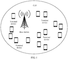
- FIG. 1 is a schematic architectural diagram of a communications system to which an embodiment of the present invention is applicable.
- the communications system includes a base station and a plurality of terminal devices.
- the communications system may be a global system for mobile communications (Global System for Mobile Communications, GSM for short), a code division multiple access (Code Division Multiple Access, CDMA for short) system, a wideband code division multiple access (Wideband Code Division Multiple Access, WCDMA for short) system, a long term evolution (Long Term Evolution, LTE for short) system, or a 5th generation (5th Generation, 5G for short) mobile communications system.
- GSM Global System for Mobile Communications
- CDMA Code Division Multiple Access
- WCDMA Wideband Code Division Multiple Access
- LTE Long Term Evolution
- 5G 5th Generation
- the base station may be a base transceiver station (Base Transceiver Station, BTS for short) in the GSM system or the CDMA system, may be a NodeB (NodeB, NB for short) in the WCDMA system, may be an evolved NodeB (evolved NodeB, eNB for short), an access point (access point, AP), or a relay station in the LTE system, or may be a base station in the 5G system. This is not limited herein.
- the terminal device may be a wireless terminal.
- the wireless terminal may refer to a device that provides a user with voice and/or data connectivity, a handheld device with a wireless connection function, or another processing device connected to a wireless modem.
- the wireless terminal may communicate with at least one core network through a radio access network (Radio Access Network, RAN).
- the wireless terminal may be a mobile terminal such as a mobile phone (or referred to as a "cellular" phone) or a computer with a mobile terminal.
- the wireless terminal may be a portable, pocket-size, handheld, computer built-in or in-vehicle mobile apparatus, which exchanges voice and/or data with the radio access network.
- the wireless terminal may also be referred to as a subscriber unit (Subscriber Unit), a subscriber station (Subscriber Station), a mobile station (Mobile Station), a mobile console (Mobile Station), a remote station (Remote Station), an access point (Access Point), a remote terminal (Remote Terminal), an access terminal (Access Terminal), a user terminal (User Terminal), user equipment (User Equipment, UE for short), or a user agent (User Agent). This is not limited herein.
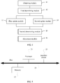
- FIG. 2 is a flowchart of an outer loop link adaptation adjustment method according to an embodiment of the present invention. As shown in FIG. 2 , the method provided in this embodiment may include the following steps.
- Step 101 A base station obtains at least one type of channel quality information of a terminal device.
- the method in this embodiment may be separately applied to uplink transmission and downlink transmission.
- the base station detects, in real time, all terminal devices that have accessed a cell, to obtain the at least one type of channel quality information of the terminal device.
- the channel quality information is quality information of an uplink channel.
- the terminal device detects channel quality information of the terminal device, and reports the detected at least one type of channel quality information to the base station.
- the channel quality information detected by the terminal device is quality information of a downlink channel.
- some terminal devices transmit data at a current moment, and some terminal devices transmit no data at the current moment. If a terminal device transmits data at the current moment, the base station can obtain channel quality information of the terminal device.
- the base station cannot obtain channel quality information of the terminal device.
- the base station may perform channel quality measurement in a random access process of the terminal device. In the random access process, the terminal device sends an access preamble (preamble) sequence, and the base station obtains at least one type of channel quality information of the terminal device through measurement.
- the terminal device has at least the following four types of channel quality information: a reference signal received power (Reference Signal Received Power, RSRP for short), a signal to interference plus noise ratio (Signal to Interference plus Noise Ratio, SINR for short), a cyclic redundancy check (Cyclic Redundancy Check, CRC for short) result, and a modulation and coding scheme (Modulation and Coding Scheme, MCS for short) of the terminal device.
- RSRP Reference Signal Received Power
- SINR Signal to Interference plus Noise Ratio
- SINR Signal to Interference plus Noise Ratio
- CRC Cyclic Redundancy Check
- MCS Modulation and Coding Scheme
- the RSRP reflects only absolute received signal strength of the terminal device, and is mainly related to a transmit power spectrum density of the terminal device, a path propagation loss in wireless space, a large/small-scale fading loss, and the like.
- the SINR reflects a ratio of signal energy to interference plus noise energy. In addition to the foregoing mentioned factors affecting the RSRP, the SINR is further closely related to interference strength in a wireless environment, actual wireless receiver performance, and the like.
- An MCS is usually selected by using an SINR in an AMC technology. The MCS is mainly determined by using different modulation schemes and bit rates.
- Common modulation schemes include quadrature phase shift keying (Quadrature Phase Shift Keying, QPSK for short), 16 quadrature amplitude modulation (Quadrature Amplitude Modulation, QAM for short), 64 QAM, and the like.
- QPSK Quadrature Phase Shift Keying
- QAM Quadrature Amplitude Modulation
- 64 QAM 64 QAM
- Different bit rates can be selected in a same modulation scheme, so that different MCS ranges are formed. For example, in an LTE system, when 64QAM is supported, there are a total of 29 MCS ranges: 0 to 28, and there are a total of three modulation schemes: QPSK, 16QAM, and the 64QAM.
- a lower MCS range leads to lower channel quality or a smaller SINR value required for performing correct transmission in a modulation and coding scheme at the range
- a higher MCS range leads to higher channel quality or a larger SINR value required for performing correct transmission in a modulation and coding scheme at the range.
- Closer MCS ranges lead to closer channel quality or SINR values required for ensuring correct transmission.
- the base station may obtain channel quality information of a plurality of terminal devices, or may obtain channel quality information of only one terminal device.
- the base station records a measurement SINR of a terminal device k at the moment t as a measurement SINR (t, k), records a CRC result of the terminal device k at the moment t as a CRC (t, k), and records an MCS used by the terminal device k at the moment t as an MCS (t, k).
- the channel quality information of the terminal device may be obtained by the base station by detecting initially transmitted data of the terminal device, or may be equivalent information obtained by the base station by combining data in a plurality of times of retransmission of the terminal device.
- the data packet may fail to be received.
- the terminal device needs to retransmit the data packet for a plurality of times, until the base station correctly receives the data packet or a quantity of retransmission times reaches a maximum quantity of retransmission times that is set in a system. Then, the terminal device stops sending the data packet.
- the base station In a retransmission scenario, the base station usually combines a plurality of pieces of received data, and then demodulates and decodes the data, to obtain a combined CRC. Therefore, a single SINR, RSRP, MCS, and the like detected in initial transmission or specific retransmission cannot match the combined CRC. Therefore, channel quality information such as SINRs, RSRPs, and MCSs obtained through measurement in a plurality of times of transmission should be combined to obtain an equivalent SINR, RSRP, and MCS, and the equivalent SINR, RSRP, and MCS match the combined CRC.
- a specific combination method is not specifically limited in this embodiment, and depends on a specific system. When an effective combination method cannot be obtained, a detection result of the initially transmitted data may be used only.
- the uplink transmission is used as an example for description in the foregoing method, the method is also applicable to the downlink transmission.
- the terminal device performs CRC combination, and combines channel quality information such as SINRs, RSRPs, and MCSs.
- Step 102 The base station determines, based on the at least one type of channel quality information of the terminal device and channel quality ranges of a plurality of clusters in a cell, a target cluster to which the terminal device belongs.
- the cell of the base station includes the plurality of clusters
- the plurality of clusters may be obtained through classification by the base station based on the channel quality ranges in advance, and the channel quality ranges of all the clusters are different.
- an SINR is not only related to a channel environment, but also related to performance of a receiver used by a receive end device. Therefore, when receiver types are different or there is a difference in receiver performance, the cell needs to first classify different receivers, and then perform cluster classification for each type of receiver according to the following method. For example, in the uplink transmission, the base station may use a plurality of receiver algorithms, and performance in the plurality of receiver algorithms is different.
- the base station first performs classification according to the receiver algorithms, and then performs, according to the following method, cluster classification for data of the terminal device that is received by each type of receiver.
- performance of receivers of terminal devices of different vendors or models may be different.
- the base station first performs classification based on a difference between the terminal devices, and then performs cluster classification on data of each type of terminal device according to the following method.
- the base station may perform cluster classification based on one or more parameters in the channel quality information of the terminal device, for example, an RSRP, a measurement SINR, and an MCS in use.
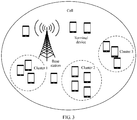
- FIG. 3 is a schematic diagram of cluster classification in a cell. As shown in FIG. 3 , the cell includes three clusters: a cluster 1, a cluster 2, and a cluster 3. It is assumed that the three clusters are obtained through classification based on an MCS range. For example, in an LTE system, an uplink channel includes a total of 29 MCS ranges: 0 to 28, and the 29 MCS ranges are classified into the three clusters.
- a channel quality range of the cluster 1 may be MCS ranges 0 to 10
- a channel quality range of the cluster 2 may be MCS ranges 11 to 20
- a channel quality range of the cluster 3 may be MCS ranges 21 to 28.
- FIG. 3 is merely an example for description, and the cell may include more or fewer than three clusters.
- a value range of the SINR is usually -10 dB to 30 dB.
- a larger value of the SINR indicates better channel quality.
- Terminal devices in the cell may be classified into five clusters based on the SINR.
- a channel quality range of a cluster 1 may be SINRs less than 3
- a channel quality range of a cluster 2 may be SINRs ranging from 3 to 10
- a channel quality range of a cluster 3 may be SINRs ranging from 11 to 15
- a channel quality range of a cluster 4 may be SINRs ranging from 16 to 25
- a channel quality range of a cluster 5 may be SINRs greater than 25.
- a value range of the RSRP is usually -140 dbm to -40 dbm. A larger value of the RSRP indicates better channel quality. Terminal devices in the cell may be classified into five clusters based on the RSRP.
- a channel quality range of a cluster 1 may be RSRPs less than -115 dbm
- a channel quality range of a cluster 2 may be RSRPs ranging from -115 dbm to -105 dbm
- a channel quality range of a cluster 3 may be RSRPs ranging from -105 dbm to -95 dbm
- a channel quality range of a cluster 4 may be RSRPs ranging from -95 dbm to -85 dbm
- a channel quality range of a cluster 5 may be RSRPs greater than -85 dbm.
- the base station can determine, based on only the one type of channel quality information obtained in step 101, the target cluster to which the terminal device belongs. If the base station obtains a plurality of types of channel quality information in step 101, the base station may determine, based on one or more of the plurality of types of channel quality information, the target cluster to which the terminal device belongs. Specifically, when cluster classification is performed based on an RSRP, the base station determines whether the measurement RSRP of the terminal device belongs to an RSRP range corresponding to each cluster, and when the measurement RSRP of the terminal device belongs to an RSRP range corresponding to a cluster, the base station determines that the cluster is the target cluster to which the terminal device belongs.
- the base station determines whether the MCS used by the terminal device belongs to an MCS range corresponding to each cluster, and when the MCS used by the terminal device belongs to an MCS range corresponding to a cluster, the base station determines that the cluster is the target cluster to which the terminal device belongs.
- cluster classification is performed based on an SINR
- the base station determines whether the measurement SINR of the terminal device belongs to an SINR range corresponding to each cluster, and when the measurement SINR of the terminal device belongs to an SINR range corresponding to a cluster, the base station determines that the cluster is the target cluster to which the terminal device belongs.
- classification is performed by making a comprehensive decision based on a plurality of groups of range thresholds for a plurality of measurement quantities.
- the base station performs cluster classification on the terminal device based on the at least one type of channel quality information of the terminal device.
- Information with similar characteristics may be classified into a same cluster, and terminal devices in a same cluster have similar measurement SINR errors.
- a cluster to which each terminal device belongs is determined based on a current measurement result.
- a same terminal device may belong to different clusters at different moments. In other words, terminal devices in each cluster all change dynamically.
- Step 103 The base station updates an SINR error adjustment amount of the target cluster based on the at least one type of channel quality information of the terminal device.
- the base station needs to maintain an SINR error adjustment amount for each cluster, and maintain a channel quality fluctuation parameter of the cell.
- the SINR error adjustment amount is mainly used to compensate for an SINR measurement error.
- the channel quality fluctuation parameter of the cell is mainly used to compensate for an SINR fluctuation caused by a time variation of a wireless channel, or the like.
- An initial value of the SINR error adjustment amount of each cluster is a fixed value preconfigured for the base station. Initial values of SINR error adjustment amounts of all clusters may be the same or may be different. Subsequently, the SINR error adjustment amount of each cluster is updated based on channel quality information of a terminal device in the cluster.
- the base station If an initial value of an SINR error adjustment amount of a cluster 1 is A, and channel quality information of three terminal devices is detected at the moment t, the base station first updates the SINR error adjustment amount from the initial value A to A + ⁇ 1 based on channel quality information of a terminal device 1, then updates the SINR error adjustment amount from A + ⁇ 1 to A + ⁇ 1 + ⁇ 2 based on channel quality information of a terminal device 2, and subsequently updates the SINR error adjustment amount from A + ⁇ 1 + ⁇ 2 to A + ⁇ 1 + ⁇ 2 + ⁇ 3 based on channel quality information of a terminal device 3, where each of values of ⁇ 1, ⁇ 2 , and ⁇ 3 may be a positive number, 0, or a negative number.
- the base station may first update a real block error rate and a hard decision block error rate of the target cluster based on the at least one type of channel quality information of the terminal device, and then update the SINR error adjustment amount of the target cluster based on an updated real block error rate of the target cluster and an updated hard decision block error rate of the target cluster, to eliminate a measurement error. If the base station obtains only one type of channel quality information in step 101, the base station can update the real block error rate and the hard decision block error rate of the target cluster based on only the one type of channel quality information obtained in step 101. If the base station obtains a plurality of types of channel quality information in step 101, the base station may update the real block error rate and the hard decision block error rate of the target cluster based on one or more of the plurality of types of channel quality information.
- the base station updates the real block error rate and the hard decision block error rate of the target cluster based on a measurement SINR of the terminal device, a CRC result, and an MCS used by the terminal device. Details are as follows:
- AdjStep is mainly used to weigh tracking, a convergence speed, and stability of an adjustment algorithm. For different systems and scenarios, AdjStep may be adjusted based on a requirement, to select optimal AdjStep.
- Step 104 The base station updates a channel quality fluctuation parameter of the cell based on the at least one type of channel quality information of the terminal device.
- the channel quality fluctuation parameter of the cell is mainly used to compensate for an SINR fluctuation caused by a time variation of a wireless channel, or the like.
- the SINR fluctuation is usually related to a wireless channel physical environment (including large/small-scale fading and the like), a change of co-channel interference caused by a neighboring cell on a serving cell, and the like.
- a cell In an actual wireless network, a cell always serves terminal devices in a fixed physical area, and the terminal devices in the cell have similar wireless channel physical environments. Due to randomness of terminal device behavior in the entire wireless network, a pattern of wireless interference on a terminal device also tends to be random.
- the base station collects real-time statistics of a channel quality fluctuation parameter generated by each terminal device in the cell, and obtains the channel quality fluctuation parameter of the cell based on the channel quality fluctuation parameter generated by each terminal device.
- the base station may use the channel quality fluctuation parameter of the cell as a reference of a channel quality fluctuation status of the terminal device.
- the channel quality fluctuation parameter of the cell includes one or more of the following parameters: an SINR fluctuation variance, an interference intensity change amount, a Doppler frequency shift value, and a moving speed and a physical environment of the terminal device.
- the physical environment is a dense urban area or an open suburb.
- an SINR fluctuation variance may also be processed based on cluster classification. Details are not described herein.
- the base station updates the SINR fluctuation variance of the cell based on the channel quality information of the terminal device. Details are as follows: The base station first updates an average SINR of the cell based on the measurement SINR of the terminal device.
- the measurement SINR is usually an instantaneous measurement value.
- the base station may obtain the average SINR of the cell by performing temporal filtering on the measurement SINR.
- Step 105 When no initial value of an OLLA adjustment amount is set for the terminal device, the base station determines an initial value of the OLLA adjustment amount of the terminal device based on an updated SINR error adjustment amount of the target cluster and an updated channel quality fluctuation parameter of the cell.
- step 104 the base station needs to determine whether the initial value of the OLLA adjustment amount is set for the terminal device. If the base station sets no initial value of the OLLA adjustment amount for the terminal device, step 105 is performed, or if the base station has set the initial value of the OLLA adjustment amount for the terminal device, step 106 is directly performed after step 104.
- a value of b may be adjusted based on different requirements. For example, in an LTE system, an IBLER of a data service transmitted on a PUSCH needs to be less than 10%, and if an SINR fluctuation is approximately Gaussian distribution, b is set to 1.23.
- the measurement SINR of the terminal device is compensated from two dimensions: the SINR measurement error and the SINR fluctuation, and a channel quality difference between different terminal devices is considered during compensation, so that the initial value of the OLLA adjustment amount of the terminal device is more accurate. Finally, all terminal devices in the cell can obtain optimal initial values of OLLA adjustment amounts.
- each terminal device has an optimal initial value of an OLLA adjustment amount, and in most scenarios, initial values of OLLA adjustment amounts of all terminal devices are different.
- each terminal device requires sufficient data samples for convergence of the initial values of the OLLA adjustment amounts. If no cluster classification is performed on the terminal devices in the cell, convergence of the initial values of the OLLA adjustment amounts may be performed by using data samples of all the terminal devices.
- a finally obtained initial value of the OLLA adjustment amount is an average statistical result of all the terminal devices, and there is still a large difference between the average statistical result and the optimal initial value of the OLLA adjustment amount of each terminal device.
- terminal devices with similar optimal initial values of OLLA adjustment amounts are classified into one cluster by using a cluster classification method, so that a relatively small difference can be ensured between an optimal initial value of an OLLA adjustment amount of an individual terminal device and a statistical initial value of an OLLA adjustment amount in the cluster, and sufficient data samples in each cluster can also be ensured to implement convergence of initial values of OLLA adjustment amounts.
- Step 106 Based on the initial value of the OLLA adjustment amount of the terminal device, the base station adjusts a measurement SINR of the terminal device, and updates the OLLA adjustment amount of the terminal device, until the OLLA adjustment amount of the terminal device meets a convergence condition.
- the base station obtains a measurement SINR of the terminal device in a current transmission time unit.
- the transmission time unit may be a minimum transmission unit in an existing communications system, for example, a transmission time interval (Transmission Time Interval, TTI for short) in an LTE system. With development of the communications system, the transmission time unit may change.
- the base station When the measurement SINR is adjusted for the first time, the base station adds the measurement SINR of the terminal device to the initial value of the OLLA adjustment amount of the terminal device to obtain an adjusted SINR, and then selects, based on the preset SINR threshold table, an MCS corresponding to the adjusted SINR.
- the MCS corresponding to the adjusted SINR is an MCS used by the terminal device in a next transmission time unit.
- the convergence condition may be a target IBLER value. For example, the target value is 10%.
- the terminal device transmits data by using the MCS corresponding to the adjusted SINR.
- the base station measures an IBLER of the terminal device, and compares an IBLER obtained through measurement with the target IBLER value.
- the base station updates the OLLA adjustment amount by using a preset adjustment step size. After the OLLA adjustment amount is updated, the measurement SINR of the terminal device is adjusted by using an updated OLLA adjustment amount, and the foregoing process is repeated, until an updated OLLA adjustment amount meets the convergence condition. Then, it is determined that the OLLA adjustment amount is an OLLA adjustment amount used by the terminal device.
- the base station obtains the at least one piece of channel quality information of the terminal device, determines, based on the at least one piece of channel quality information of the terminal device and the channel quality ranges of the plurality of clusters in the cell, the target cluster to which the terminal device belongs, updates the SINR error adjustment amount of the target cluster and the channel quality fluctuation parameter of the cell based on the at least one piece of channel quality information of the terminal device, and finally determines the initial value of the OLLA adjustment amount of the terminal device based on the SINR error adjustment amount of the target cluster and the channel quality fluctuation parameter of the cell.
- the initial value of the OLLA adjustment amount of the terminal device is determined from two dimensions: the SINR measurement error and the SINR fluctuation, and a channel quality difference between different terminal devices is considered during adjustment, so that the initial value of the OLLA adjustment amount of the terminal device is more accurate.
- FIG. 4 is a schematic structural diagram of an outer loop link adaptation adjustment apparatus according to an embodiment of the present invention. As shown in FIG. 4 , the apparatus includes:
- the channel quality information of the terminal device includes the measurement SINR of the terminal device, an RSRP, a CRC result, and an MCS used by the terminal device.
- the first update module 13 is specifically configured to: update a real block error rate and a hard decision block error rate of the target cluster based on the at least one type of channel quality information of the terminal device, and update the SINR error adjustment amount of the target cluster based on an updated real block error rate of the target cluster and an updated hard decision block error rate of the target cluster.
- the first update module 13 is specifically configured to: obtain a correction SINR based on a sum of the SINR error adjustment amount of the target cluster and the measurement SINR of the terminal device; obtain, based on the MCS used by the terminal device, an SINR threshold corresponding to the MCS used by the terminal device; compare the correction SINR with the SINR threshold corresponding to the MCS used by the terminal device, to obtain a CRC hard decision result; update the real block error rate of the target cluster based on the CRC result; and update the hard decision block error rate of the target cluster based on the CRC hard decision result.
- the first update module 13 is specifically configured to compare the correction SINR with the SINR threshold corresponding to the MCS used by the terminal device, where the CRC hard decision result is 0 if the correction SINR is greater than the SINR threshold corresponding to the MCS used by the terminal device, or the CRC hard decision result is 1 if the correction SINR is less than or equal to the SINR threshold corresponding to the MCS used by the terminal device.
- FIG. 5 is a schematic structural diagram of another outer loop link adaptation adjustment apparatus according to an embodiment of the present invention. As shown in FIG. 5 , the apparatus includes a processor 21, a memory 22, an interface circuit 23, and a bus 24.
- the processor 21, the memory 22, and the interface circuit 23 are connected and complete mutual communication by using the bus 24, and the processor 21 interacts with another apparatus by using the interface circuit 23.
- the memory 22 stores a group of program code, and the processor 21 invokes the program code stored in the memory 22, to perform the following operations:
- the channel quality information of the terminal device includes the measurement SINR of the terminal device, a reference signal received power RSRP, a cyclic redundancy check CRC result, and an MCS used by the terminal device.
- the processor 21 is specifically configured to: update a real block error rate and a hard decision block error rate of the target cluster based on the at least one type of channel quality information of the terminal device, and update the SINR error adjustment amount of the target cluster based on an updated real block error rate of the target cluster and an updated hard decision block error rate of the target cluster.
- the processor 21 is specifically configured to: obtain a correction SINR based on a sum of the SINR error adjustment amount of the target cluster and the measurement SINR of the terminal device; obtain, based on the MCS used by the terminal device, an SINR threshold corresponding to the MCS used by the terminal device; compare the correction SINR with the SINR threshold corresponding to the MCS used by the terminal device, to obtain a CRC hard decision result; update the real block error rate of the target cluster based on the CRC result; and update the hard decision block error rate of the target cluster based on the CRC hard decision result.
- the processor 21 is specifically configured to compare the correction SINR with the SINR threshold corresponding to the MCS used by the terminal device, where the CRC hard decision result is 0 if the correction SINR is greater than the SINR threshold corresponding to the MCS used by the terminal device, or the CRC hard decision result is 1 if the correction SINR is less than or equal to the SINR threshold corresponding to the MCS used by the terminal device.
- the disclosed apparatus and method may be implemented in other manners.
- the described apparatus embodiment is merely an example.
- the unit division is merely logical function division and may be other division in actual implementation.
- a plurality of units or components may be combined or integrated into another system, or some features may be ignored or not performed.
- the displayed or discussed mutual couplings or direct couplings or communication connections may be implemented through some interfaces.
- the indirect couplings or communication connections between the apparatuses or units may be implemented in electronic, mechanical, or other forms.
- the units described as separate parts may or may not be physically separate, and parts displayed as units may or may not be physical units, may be located in one position, or may be distributed on a plurality of network units. Some or all of the units may be selected based on actual requirements to achieve the objectives of the solutions of the embodiments.
- functional units in the embodiments of the present invention may be integrated into one processing unit, or each of the units may exist alone physically, or two or more units are integrated into one unit.
- the integrated unit may be implemented in a form of hardware, or may be implemented in a form of hardware in addition to a software functional unit.
- the integrated unit may be stored in a computer-readable storage medium.
- the software functional unit is stored in a storage medium and includes several instructions for instructing a computer device (which may be a personal computer, a server, a network device, or the like) or a processor (English: processor) to perform some of the steps of the methods described in the embodiments of the present invention.
- the foregoing storage medium includes: any medium that can store program code, such as a USB flash drive, a removable hard disk, a read-only memory (English: Read-Only Memory, ROM for short), a random access memory (English: Random Access Memory, RAM for short), a magnetic disk, or an optical disc.
Landscapes
- Engineering & Computer Science (AREA)
- Computer Networks & Wireless Communication (AREA)
- Signal Processing (AREA)
- Quality & Reliability (AREA)
- Physics & Mathematics (AREA)
- Artificial Intelligence (AREA)
- Probability & Statistics with Applications (AREA)
- Mobile Radio Communication Systems (AREA)
- Electromagnetism (AREA)
Description
- Embodiments of the present invention relate to communications technologies, and in particular, to an outer loop link adaptation (Outer Loop Link Adaptation, OLLA for short) adjustment method and apparatus.
- An adaptive modulation and coding (Adaptive Modulation and coding, AMC for short) technology is widely used in a wireless transmission system. In the technology, a modulation and coding scheme (Modulation Coding Scheme, MCS for short) used by a communications system is adjusted to adapt to constantly changing wireless channel quality, thereby improving wireless transmission reliability and a system throughput rate. Specifically, in the technology, a signal to interference plus noise ratio (Signal to Interference Noise Ratio, SINR for short) of a wireless channel needs to be monitored to measure wireless channel quality, and channel quality at a future moment is predicted based on a measurement result. Finally, an appropriate MCS is selected based on a prediction result by searching for a preset SINR threshold table.
- Due to a non-ideal factor in an actual system and a time-varying characteristic of the wireless channel, an irremovable error exists between a predicted SINR and an actually corresponding demodulation and decoding SINR. To reduce impact of an SINR prediction error on system performance, and improve robustness of the entire system, the predicted SINR is usually adjusted through OLLA. During adjustment, an initial SINR adjustment amount (also referred to as an initial OLLA value) needs to be first set, and then a convergence adjustment is made in a small step size, until an initial block error rate (Initial Block Error Rate, IBLER for short) of a user meets a target IBLER value. Two errors mainly need to be compensated through OLLA adjustment to obtain the target IBLER value. One error, referred to as a measurement error, is a difference between a measurement SINR (or an SINR threshold) at a current moment and an actual demodulation and decoding SINR. The other error is an SINR fluctuation caused by a time variation or the like of the wireless channel.
- In different wireless environments or channel conditions, different error amounts usually need to be compensated. However, an existing initial OLLA value is a fixed initial value, and cannot reflect situations of all wireless environments. Selection of an inappropriate initial OLLA value directly causes longer time required for achieving a convergence state through OLLA adjustment, and consequently system performance is affected. In particular, for a small packet service in a mobile broadband (Mobile Broadband, MBB) service, transmission time of a data service is relatively short, and there is no sufficient data used for OLLA adjustment to implement convergence. Therefore, in an entire transmission process of the small packet service, AMC performance is greatly reduced due to a deviation of an OLLA adjustment amount.
- The article "Self-Optimization Algorithm for Outer Loop Link Adaptation in LTE", IEEE Communications Letters, vol. 19, no. 11, 1 November 2015, pages 2005-2008, ISSN: 1089-7798, proposes an algorithm adjusting the OLLA initial offset parameter based on OLLA adjustment histograms of large activity connections. At the beginning of an RRC connection, OLLA is initialized to a fixed value defined on a cell basis. OLLA compensates for systematic errors by applying an offset to estimated SINR to compute effective (corrected) SINR in order to select the proper modulation and coding scheme MCS. For the histogram, an analyzed trace connection dataset of nearly 175.000 connections is collected during 24 hours in 24 LTE cells in 4 sites selected at random.
- Embodiments of the present invention provide an outer loop link adaptation adjustment method according to claim 1 and an apparatus according to claim 9. An initial value of an OLLA adjustment amount of a terminal device is determined from two dimensions: an SINR measurement error and an SINR fluctuation, and a channel quality difference between different terminal devices is considered when the initial value of the OLLA adjustment amount is determined, so that the initial value of the OLLA adjustment amount of the terminal device is more accurate.
- A first aspect of the present invention provides an outer loop link adaptation adjustment method, including:
- obtaining, by a base station, at least one type of channel quality information of a terminal device;
- determining, by the base station based on the at least one type of channel quality information of the terminal device and channel quality ranges of a plurality of clusters in a cell, a target cluster to which the terminal device belongs;
- updating, by the base station, a signal to interference plus noise ratio SINR error adjustment amount of the target cluster based on the at least one type of channel quality information of the terminal device;
- updating, by the base station, a channel quality fluctuation parameter of the cell based on the at least one type of channel quality information of the terminal device;
- if no initial value of an outer loop link adaptation OLLA adjustment amount is set for the terminal device, determining, by the base station, an initial value of the OLLA adjustment amount of the terminal device based on an updated SINR error adjustment amount of the target cluster and an updated channel quality fluctuation parameter of the cell; and
- based on the initial value of the OLLA adjustment amount of the terminal device, adjusting, by the base station, a measurement SINR of the terminal device, and updating the OLLA adjustment amount of the terminal device, until the OLLA adjustment amount of the terminal device meets a convergence condition.
- Optionally, the channel quality information of the terminal device includes the measurement SINR of the terminal device, a reference signal received power RSRP, a cyclic redundancy check CRC result, and an MCS used by the terminal device.
- Optionally, the updating, by the base station, an SINR error adjustment amount of the target cluster based on the at least one type of channel quality information of the terminal device is specifically: updating, by the base station, a real block error rate and a hard decision block error rate of the target cluster based on the at least one type of channel quality information of the terminal device; and updating, by the base station, the SINR error adjustment amount of the target cluster based on an updated real block error rate of the target cluster and an updated hard decision block error rate of the target cluster.
- Optionally, the updating, by the base station, a real block error rate and a hard decision block error rate of the target cluster based on the at least one type of channel quality information of the terminal device is specifically: obtaining, by the base station, a correction SINR based on a sum of the SINR error adjustment amount of the target cluster and the measurement SINR of the terminal device; obtaining, by the base station based on the MCS used by the terminal device, an SINR threshold corresponding to the MCS used by the terminal device; comparing, by the base station, the correction SINR with the SINR threshold corresponding to the MCS used by the terminal device, to obtain a CRC hard decision result; updating, by the base station, the real block error rate of the target cluster based on the CRC result; and updating, by the base station, the hard decision block error rate of the target cluster based on the CRC hard decision result.
- Optionally, the comparing, by the base station, the correction SINR with the SINR threshold corresponding to the MCS used by the terminal device, to obtain a CRC hard decision result is specifically: comparing, by the base station, the correction SINR with the SINR threshold corresponding to the MCS used by the terminal device, where the CRC hard decision result is 0 if the correction SINR is greater than the SINR threshold corresponding to the MCS used by the terminal device, or the CRC hard decision result is 1 if the correction SINR is less than or equal to the SINR threshold corresponding to the MCS used by the terminal device.
- Optionally, the updating, by the base station, the real block error rate of the target cluster based on the CRC result includes:
- updating, by the base station, the real block error rate of the target cluster according to the following formula:

- IblerMeas represents the real block error rate of the target cluster, a represents a filter coefficient, and CRC represents the CRC result; and
- the updating, by the base station, the hard decision block error rate of the target cluster based on the CRC hard decision result includes:
- updating, by the base station, the hard decision block error rate of the target cluster according to the following formula:

- IblerJudge represents the hard decision block error rate of the target cluster, and JudgeCRC represents the CRC hard decision result.
- updating, by the base station, the hard decision block error rate of the target cluster according to the following formula:
- Optionally, the updating, by the base station, the SINR error adjustment amount of the target cluster based on an updated real block error rate of the target cluster and an updated hard decision block error rate of the target cluster is specifically:
- updating, by the base station, the SINR error adjustment amount of the target cluster according to the following formula:

- SinrAdj is the SINR error adjustment amount of the target cluster, IblerJudge is the updated hard decision block error rate of the target cluster, IblerMeas is the updated real block error rate of the target cluster, and Adj Step is an adjustment step size.
- Optionally, the channel quality fluctuation parameter of the cell is an SINR fluctuation variance of the cell, and the updating, by the base station, a channel quality fluctuation parameter of the cell based on the channel quality information of the terminal device is specifically:
- updating, by the base station, an average SINR of the cell based on the measurement SINR of the terminal device; and
- updating, by the base station, the SINR fluctuation variance of the cell according to the following formula:

- CellSinrVar is the SINR fluctuation variance of the cell, SINR is the measurement SINR of the terminal device, AvgSinr is the average SINR of the cell, and a represents a filter coefficient.
- Optionally, the determining, by the base station, an initial value of the OLLA adjustment amount of the terminal device based on an updated SINR error adjustment amount of the target cluster and an updated SINR fluctuation variance of the cell includes:
- calculating, by the base station, the initial value of the OLLA adjustment amount of the terminal device according to the following formula:

- SinrAdj represents the SINR error adjustment amount of the target cluster, CellSinrVar is the SINR fluctuation variance of the cell, b represents a fluctuation compensation filter coefficient, and sqrt() represents a square root extraction operation.
- A second aspect of the present invention provides an outer loop link adaptation adjustment appartus, including:
- an obtaining module, configured to obtain at least one type of channel quality information of a terminal device;
- a first determining module, configured to determine, based on the at least one type of channel quality information of the terminal device and channel quality ranges of a plurality of clusters in a cell, a target cluster to which the terminal device belongs;
- a first update module, configured to update a signal to interference plus noise ratio SINR error adjustment amount of the target cluster based on the at least one type of channel quality information of the terminal device;
- a second update module, configured to update a channel quality fluctuation parameter of the cell based on the at least one type of channel quality information of the terminal device;
- a second determining module, configured to: if no initial value of an outer loop link adaptation OLLA adjustment amount is set for the terminal device, determine an initial value of the OLLA adjustment amount of the terminal device based on an updated SINR error adjustment amount of the target cluster and an updated channel quality fluctuation parameter of the cell; and
- an adjustment module, configured to: based on the initial value of the OLLA adjustment amount of the terminal device, adjust a measurement SINR of the terminal device, and update the OLLA adjustment amount of the terminal device, until the OLLA adjustment amount of the terminal device meets a convergence condition.
- Optionally, the channel quality information of the terminal device includes the measurement SINR of the terminal device, a reference signal received power RSRP, a cyclic redundancy check CRC result, and an MCS used by the terminal device.
- Optionally, the first update module is specifically configured to: update a real block error rate and a hard decision block error rate of the target cluster based on the at least one type of channel quality information of the terminal device, and update the SINR error adjustment amount of the target cluster based on an updated real block error rate of the target cluster and an updated hard decision block error rate of the target cluster.
- Optionally, the first update module is specifically configured to:
- obtain a correction SINR based on a sum of the SINR error adjustment amount of the target cluster and the measurement SINR of the terminal device;
- obtain, based on the MCS used by the terminal device, an SINR threshold corresponding to the MCS used by the terminal device;
- compare the correction SINR with the SINR threshold corresponding to the MCS used by the terminal device, to obtain a CRC hard decision result;
- update the real block error rate of the target cluster based on the CRC result; and
- update the hard decision block error rate of the target cluster based on the CRC hard decision result.
- Optionally, the first update module is specifically configured to compare the correction SINR with the SINR threshold corresponding to the MCS used by the terminal device, where the CRC hard decision result is 0 if the correction SINR is greater than the SINR threshold corresponding to the MCS used by the terminal device, or the CRC hard decision result is 1 if the correction SINR is less than or equal to the SINR threshold corresponding to the MCS used by the terminal device.
- Optionally, the first update module is specifically configured to:
- update the real block error rate of the target cluster according to the following formula:

- IblerMeas represents the real block error rate of the target cluster, a represents a filter coefficient, and CRC represents the CRC result; and
- update the hard decision block error rate of the target cluster according to the following formula:

- IblerJudge represents the hard decision block error rate of the target cluster, and JudgeCRC represents the CRC hard decision result.
- Optionally, the first update module is specifically configured to:
- update the SINR error adjustment amount of the target cluster according to the following formula:

- SinrAdj is the SINR error adjustment amount of the target cluster, IblerJudge is the updated hard decision block error rate of the target cluster, IblerMeas is the updated real block error rate of the target cluster, and AdjStep is an adjustment step size.
- Optionally, the second update module is specifically configured to:
- update an average SINR of the cell based on the measurement SINR of the terminal device; and
- update an SINR fluctuation variance of the cell according to the following formula:

- CellSinrVar is the SINR fluctuation variance of the cell, SINR is the measurement SINR of the terminal device, AvgSinr is the average SINR of the cell, and a represents a filter coefficient.
- Optionally, the second determining module is specifically configured to:
- calculate the initial value of the OLLA adjustment amount of the terminal device according to the following formula:

- SinrAdj represents the SINR error adjustment amount of the target cluster, CellSinrVar is the SINR fluctuation variance of the cell, b represents a fluctuation compensation filter coefficient, and sqrt() represents a square root extraction operation.
- A third aspect of the present invention provides an outer loop link adaptation adjustment apparatus, including a memory and a processor, where the memory is configured to store a program instruction, and the processor is configured to invoke the program instruction in the memory to perform the following method:
- obtaining at least one type of channel quality information of a terminal device;
- determining, based on the at least one type of channel quality information of the terminal device and channel quality ranges of a plurality of clusters in a cell, a target cluster to which the terminal device belongs;
- updating a signal to interference plus noise ratio SINR error adjustment amount of the target cluster based on the at least one type of channel quality information of the terminal device;
- updating a channel quality fluctuation parameter of the cell based on the at least one type of channel quality information of the terminal device;
- if no initial value of an outer loop link adaptation OLLA adjustment amount is set for the terminal device, determining an initial value of the OLLA adjustment amount of the terminal device based on an updated SINR error adjustment amount of the target cluster and an updated channel quality fluctuation parameter of the cell; and
- based on the initial value of the OLLA adjustment amount of the terminal device, adjusting a measurement SINR of the terminal device, and updating the OLLA adjustment amount of the terminal device, until the OLLA adjustment amount of the terminal device meets a convergence condition.
- Optionally, the channel quality information of the terminal device includes the measurement SINR of the terminal device, a reference signal received power RSRP, a cyclic redundancy check CRC result, and an MCS used by the terminal device.
- Optionally, the processor is specifically configured to: update a real block error rate and a hard decision block error rate of the target cluster based on the at least one type of channel quality information of the terminal device, and update the SINR error adjustment amount of the target cluster based on an updated real block error rate of the target cluster and an updated hard decision block error rate of the target cluster.
- Optionally, the processor is specifically configured to: obtain a correction SINR based on a sum of the SINR error adjustment amount of the target cluster and the measurement SINR of the terminal device; obtain, based on the MCS used by the terminal device, an SINR threshold corresponding to the MCS used by the terminal device; compare the correction SINR with the SINR threshold corresponding to the MCS used by the terminal device, to obtain a CRC hard decision result; update the real block error rate of the target cluster based on the CRC result; and update the hard decision block error rate of the target cluster based on the CRC hard decision result.
- Optionally, the processor is specifically configured to compare the correction SINR with the SINR threshold corresponding to the MCS used by the terminal device, where the CRC hard decision result is 0 if the correction SINR is greater than the SINR threshold corresponding to the MCS used by the terminal device, or the CRC hard decision result is 1 if the correction SINR is less than or equal to the SINR threshold corresponding to the MCS used by the terminal device.
- Optionally, the processor is specifically configured to: update the real block error rate of the target cluster according to the following formula:

- IblerMeas represents the real block error rate of the target cluster, a represents a filter coefficient, and CRC represents the CRC result; and
- update the hard decision block error rate of the target cluster according to the following formula:

- IblerJudge represents the hard decision block error rate of the target cluster, and JudgeCRC represents the CRC hard decision result.
- Optionally, the processor is specifically configured to update the SINR error adjustment amount of the target cluster according to the following formula:

SinrAdj is the SINR error adjustment amount of the target cluster, IblerJudge is the updated hard decision block error rate of the target cluster, IblerMeas is the updated real block error rate of the target cluster, and AdjStep is an adjustment step size. - Optionally, the processor is specifically configured to: update an average SINR of the cell based on the measurement SINR of the terminal device, and then update an SINR fluctuation variance of the cell according to the following formula: CellSinrVar = CellSinrVar × (1 - a) + a × (SINR - AvgSinr)^2, where CellSinrVar is the SINR fluctuation variance of the cell, SINR is the measurement SINR of the terminal device, AvgSinr is the average SINR of the cell, and a represents a filter coefficient.
- Optionally, the processor is specifically configured to calculate the initial value of the OLLA adjustment amount of the terminal device according to the following formula: ReSinrAdj = SinrAdj - b × sqrt(CellSinrVar), where SinrAdj represents the SINR error adjustment amount of the target cluster, CellSinrVar is the SINR fluctuation variance of the cell, b represents a fluctuation compensation filter coefficient, and sqrt() represents a square root extraction operation.
- According to the outer loop link adaptation adjustment method and apparatus provided in the embodiments of the present invention, the base station obtains the at least one piece of channel quality information of the terminal device, determines, based on the at least one piece of channel quality information of the terminal device and the channel quality ranges of the plurality of clusters in the cell, the target cluster to which the terminal device belongs, updates the SINR error adjustment amount of the target cluster and the channel quality fluctuation parameter of the cell based on the at least one piece of channel quality information of the terminal device, and finally determines the initial value of the OLLA adjustment amount of the terminal device based on the SINR error adjustment amount of the target cluster and the channel quality fluctuation parameter of the cell. In the method in the embodiments, the initial value of the OLLA adjustment amount of the terminal device is determined from two dimensions: an SINR measurement error and an SINR fluctuation, and a channel quality difference between different terminal devices is considered during adjustment, so that the initial value of the OLLA adjustment amount of the terminal device is more accurate.
-
-
FIG. 1 is a schematic architectural diagram of a communications system to which an embodiment of the present invention is applicable; -
FIG. 2 is a flowchart of an outer loop link adaptation adjustment method according to an embodiment of the present invention; -
FIG. 3 is a schematic diagram of cluster classification in a cell; -
FIG. 4 is a schematic structural diagram of an outer loop link adaptation adjustment apparatus according to an embodiment of the present invention; and -
FIG. 5 is a schematic structural diagram of another outer loop link adaptation adjustment apparatus according to an embodiment of the present invention. - Embodiments of the present invention provide a method for determining an outer loop link adaptation initial value, and the method may be applied to an existing communications system.
FIG. 1 is a schematic architectural diagram of a communications system to which an embodiment of the present invention is applicable. As shown inFIG. 1 , the communications system includes a base station and a plurality of terminal devices. The communications system may be a global system for mobile communications (Global System for Mobile Communications, GSM for short), a code division multiple access (Code Division Multiple Access, CDMA for short) system, a wideband code division multiple access (Wideband Code Division Multiple Access, WCDMA for short) system, a long term evolution (Long Term Evolution, LTE for short) system, or a 5th generation (5th Generation, 5G for short) mobile communications system. Correspondingly, the base station may be a base transceiver station (Base Transceiver Station, BTS for short) in the GSM system or the CDMA system, may be a NodeB (NodeB, NB for short) in the WCDMA system, may be an evolved NodeB (evolved NodeB, eNB for short), an access point (access point, AP), or a relay station in the LTE system, or may be a base station in the 5G system. This is not limited herein. - The terminal device may be a wireless terminal. The wireless terminal may refer to a device that provides a user with voice and/or data connectivity, a handheld device with a wireless connection function, or another processing device connected to a wireless modem. The wireless terminal may communicate with at least one core network through a radio access network (Radio Access Network, RAN). The wireless terminal may be a mobile terminal such as a mobile phone (or referred to as a "cellular" phone) or a computer with a mobile terminal. For example, the wireless terminal may be a portable, pocket-size, handheld, computer built-in or in-vehicle mobile apparatus, which exchanges voice and/or data with the radio access network. The wireless terminal may also be referred to as a subscriber unit (Subscriber Unit), a subscriber station (Subscriber Station), a mobile station (Mobile Station), a mobile console (Mobile Station), a remote station (Remote Station), an access point (Access Point), a remote terminal (Remote Terminal), an access terminal (Access Terminal), a user terminal (User Terminal), user equipment (User Equipment, UE for short), or a user agent (User Agent). This is not limited herein.
-
FIG. 2 is a flowchart of an outer loop link adaptation adjustment method according to an embodiment of the present invention. As shown inFIG. 2 , the method provided in this embodiment may include the following steps. - Step 101: A base station obtains at least one type of channel quality information of a terminal device.
- The method in this embodiment may be separately applied to uplink transmission and downlink transmission. For the uplink transmission, the base station detects, in real time, all terminal devices that have accessed a cell, to obtain the at least one type of channel quality information of the terminal device. The channel quality information is quality information of an uplink channel. For the downlink transmission, the terminal device detects channel quality information of the terminal device, and reports the detected at least one type of channel quality information to the base station. The channel quality information detected by the terminal device is quality information of a downlink channel. Among the terminal devices that have accessed the cell, some terminal devices transmit data at a current moment, and some terminal devices transmit no data at the current moment. If a terminal device transmits data at the current moment, the base station can obtain channel quality information of the terminal device. If a terminal device transmits no data at the current moment, the base station cannot obtain channel quality information of the terminal device. For a newly accessing terminal device, because the terminal device transmits no data, the base station may perform channel quality measurement in a random access process of the terminal device. In the random access process, the terminal device sends an access preamble (preamble) sequence, and the base station obtains at least one type of channel quality information of the terminal device through measurement.
- The terminal device has at least the following four types of channel quality information: a reference signal received power (Reference Signal Received Power, RSRP for short), a signal to interference plus noise ratio (Signal to Interference plus Noise Ratio, SINR for short), a cyclic redundancy check (Cyclic Redundancy Check, CRC for short) result, and a modulation and coding scheme (Modulation and Coding Scheme, MCS for short) of the terminal device.
- The RSRP reflects only absolute received signal strength of the terminal device, and is mainly related to a transmit power spectrum density of the terminal device, a path propagation loss in wireless space, a large/small-scale fading loss, and the like. The SINR reflects a ratio of signal energy to interference plus noise energy. In addition to the foregoing mentioned factors affecting the RSRP, the SINR is further closely related to interference strength in a wireless environment, actual wireless receiver performance, and the like. An MCS is usually selected by using an SINR in an AMC technology. The MCS is mainly determined by using different modulation schemes and bit rates. Common modulation schemes include quadrature phase shift keying (Quadrature Phase Shift Keying, QPSK for short), 16 quadrature amplitude modulation (Quadrature Amplitude Modulation, QAM for short), 64 QAM, and the like. Different bit rates can be selected in a same modulation scheme, so that different MCS ranges are formed. For example, in an LTE system, when 64QAM is supported, there are a total of 29 MCS ranges: 0 to 28, and there are a total of three modulation schemes: QPSK, 16QAM, and the 64QAM. In addition, a lower MCS range leads to lower channel quality or a smaller SINR value required for performing correct transmission in a modulation and coding scheme at the range, and a higher MCS range leads to higher channel quality or a larger SINR value required for performing correct transmission in a modulation and coding scheme at the range. Closer MCS ranges lead to closer channel quality or SINR values required for ensuring correct transmission.
- At a moment t, the base station may obtain channel quality information of a plurality of terminal devices, or may obtain channel quality information of only one terminal device. When obtaining the channel quality information of the plurality of terminal devices, the base station records a measurement SINR of a terminal device k at the moment t as a measurement SINR (t, k), records a CRC result of the terminal device k at the moment t as a CRC (t, k), and records an MCS used by the terminal device k at the moment t as an MCS (t, k). When the CRC check succeeds, the CRC (t, k) = 0. When CRC check fails, the CRC (t, k) = 1.
- For example, in the uplink transmission, the channel quality information of the terminal device may be obtained by the base station by detecting initially transmitted data of the terminal device, or may be equivalent information obtained by the base station by combining data in a plurality of times of retransmission of the terminal device. After the terminal device initially transmits a data packet, the data packet may fail to be received. The terminal device needs to retransmit the data packet for a plurality of times, until the base station correctly receives the data packet or a quantity of retransmission times reaches a maximum quantity of retransmission times that is set in a system. Then, the terminal device stops sending the data packet. In a retransmission scenario, the base station usually combines a plurality of pieces of received data, and then demodulates and decodes the data, to obtain a combined CRC. Therefore, a single SINR, RSRP, MCS, and the like detected in initial transmission or specific retransmission cannot match the combined CRC. Therefore, channel quality information such as SINRs, RSRPs, and MCSs obtained through measurement in a plurality of times of transmission should be combined to obtain an equivalent SINR, RSRP, and MCS, and the equivalent SINR, RSRP, and MCS match the combined CRC. A specific combination method is not specifically limited in this embodiment, and depends on a specific system. When an effective combination method cannot be obtained, a detection result of the initially transmitted data may be used only. Although the uplink transmission is used as an example for description in the foregoing method, the method is also applicable to the downlink transmission. During the downlink transmission, the terminal device performs CRC combination, and combines channel quality information such as SINRs, RSRPs, and MCSs.
- Step 102: The base station determines, based on the at least one type of channel quality information of the terminal device and channel quality ranges of a plurality of clusters in a cell, a target cluster to which the terminal device belongs.
- In this embodiment, the cell of the base station includes the plurality of clusters, the plurality of clusters may be obtained through classification by the base station based on the channel quality ranges in advance, and the channel quality ranges of all the clusters are different. It should be specially noted that, as an important measure indicator of channel quality, an SINR is not only related to a channel environment, but also related to performance of a receiver used by a receive end device. Therefore, when receiver types are different or there is a difference in receiver performance, the cell needs to first classify different receivers, and then perform cluster classification for each type of receiver according to the following method. For example, in the uplink transmission, the base station may use a plurality of receiver algorithms, and performance in the plurality of receiver algorithms is different. The base station first performs classification according to the receiver algorithms, and then performs, according to the following method, cluster classification for data of the terminal device that is received by each type of receiver. In the downlink transmission, performance of receivers of terminal devices of different vendors or models may be different. The base station first performs classification based on a difference between the terminal devices, and then performs cluster classification on data of each type of terminal device according to the following method.
- Specifically, the base station may perform cluster classification based on one or more parameters in the channel quality information of the terminal device, for example, an RSRP, a measurement SINR, and an MCS in use.
FIG. 3 is a schematic diagram of cluster classification in a cell. As shown inFIG. 3 , the cell includes three clusters: a cluster 1, a cluster 2, and a cluster 3. It is assumed that the three clusters are obtained through classification based on an MCS range. For example, in an LTE system, an uplink channel includes a total of 29 MCS ranges: 0 to 28, and the 29 MCS ranges are classified into the three clusters. A channel quality range of the cluster 1 may be MCS ranges 0 to 10, a channel quality range of the cluster 2 may be MCS ranges 11 to 20, and a channel quality range of the cluster 3 may be MCS ranges 21 to 28.FIG. 3 is merely an example for description, and the cell may include more or fewer than three clusters. - When cluster classification is performed based on an SINR, a value range of the SINR is usually -10 dB to 30 dB. A larger value of the SINR indicates better channel quality. Terminal devices in the cell may be classified into five clusters based on the SINR. A channel quality range of a cluster 1 may be SINRs less than 3, a channel quality range of a cluster 2 may be SINRs ranging from 3 to 10, a channel quality range of a cluster 3 may be SINRs ranging from 11 to 15, a channel quality range of a cluster 4 may be SINRs ranging from 16 to 25, and a channel quality range of a cluster 5 may be SINRs greater than 25.
- When cluster classification is performed based on an RSRP, a value range of the RSRP is usually -140 dbm to -40 dbm. A larger value of the RSRP indicates better channel quality. Terminal devices in the cell may be classified into five clusters based on the RSRP. A channel quality range of a cluster 1 may be RSRPs less than -115 dbm, a channel quality range of a cluster 2 may be RSRPs ranging from -115 dbm to -105 dbm, a channel quality range of a cluster 3 may be RSRPs ranging from -105 dbm to -95 dbm, a channel quality range of a cluster 4 may be RSRPs ranging from -95 dbm to -85 dbm, and a channel quality range of a cluster 5 may be RSRPs greater than -85 dbm.
- If the base station obtains only one type of channel quality information in
step 101, the base station can determine, based on only the one type of channel quality information obtained instep 101, the target cluster to which the terminal device belongs. If the base station obtains a plurality of types of channel quality information instep 101, the base station may determine, based on one or more of the plurality of types of channel quality information, the target cluster to which the terminal device belongs. Specifically, when cluster classification is performed based on an RSRP, the base station determines whether the measurement RSRP of the terminal device belongs to an RSRP range corresponding to each cluster, and when the measurement RSRP of the terminal device belongs to an RSRP range corresponding to a cluster, the base station determines that the cluster is the target cluster to which the terminal device belongs. When cluster classification is performed based on an MCS, the base station determines whether the MCS used by the terminal device belongs to an MCS range corresponding to each cluster, and when the MCS used by the terminal device belongs to an MCS range corresponding to a cluster, the base station determines that the cluster is the target cluster to which the terminal device belongs. When cluster classification is performed based on an SINR, the base station determines whether the measurement SINR of the terminal device belongs to an SINR range corresponding to each cluster, and when the measurement SINR of the terminal device belongs to an SINR range corresponding to a cluster, the base station determines that the cluster is the target cluster to which the terminal device belongs. Alternatively, classification is performed by making a comprehensive decision based on a plurality of groups of range thresholds for a plurality of measurement quantities. - In this embodiment, the base station performs cluster classification on the terminal device based on the at least one type of channel quality information of the terminal device. Information with similar characteristics may be classified into a same cluster, and terminal devices in a same cluster have similar measurement SINR errors. It should be specially noted that, due to mobility of the terminal device, switching between different receiver methods, or the like, behavior such as cell handover or a channel quality characteristic change in a same cell may occur on a same terminal device. Therefore, a cluster to which each terminal device belongs is determined based on a current measurement result. Overall, a same terminal device may belong to different clusters at different moments. In other words, terminal devices in each cluster all change dynamically.
- Step 103: The base station updates an SINR error adjustment amount of the target cluster based on the at least one type of channel quality information of the terminal device.
- In this embodiment, the base station needs to maintain an SINR error adjustment amount for each cluster, and maintain a channel quality fluctuation parameter of the cell. The SINR error adjustment amount is mainly used to compensate for an SINR measurement error. The channel quality fluctuation parameter of the cell is mainly used to compensate for an SINR fluctuation caused by a time variation of a wireless channel, or the like. An initial value of the SINR error adjustment amount of each cluster is a fixed value preconfigured for the base station. Initial values of SINR error adjustment amounts of all clusters may be the same or may be different. Subsequently, the SINR error adjustment amount of each cluster is updated based on channel quality information of a terminal device in the cluster. If an initial value of an SINR error adjustment amount of a cluster 1 is A, and channel quality information of three terminal devices is detected at the moment t, the base station first updates the SINR error adjustment amount from the initial value A to A + Δ1 based on channel quality information of a terminal device 1, then updates the SINR error adjustment amount from A + Δ1 to A + Δ1 + Δ2 based on channel quality information of a terminal device 2, and subsequently updates the SINR error adjustment amount from A + Δ1 + Δ2 to A + Δ1 + Δ2 + Δ3 based on channel quality information of a terminal device 3, where each of values of Δ1, Δ2 , and Δ3 may be a positive number, 0, or a negative number.
- Specifically, the base station may first update a real block error rate and a hard decision block error rate of the target cluster based on the at least one type of channel quality information of the terminal device, and then update the SINR error adjustment amount of the target cluster based on an updated real block error rate of the target cluster and an updated hard decision block error rate of the target cluster, to eliminate a measurement error. If the base station obtains only one type of channel quality information in
step 101, the base station can update the real block error rate and the hard decision block error rate of the target cluster based on only the one type of channel quality information obtained instep 101. If the base station obtains a plurality of types of channel quality information instep 101, the base station may update the real block error rate and the hard decision block error rate of the target cluster based on one or more of the plurality of types of channel quality information. - In the following example, the base station updates the real block error rate and the hard decision block error rate of the target cluster based on a measurement SINR of the terminal device, a CRC result, and an MCS used by the terminal device. Details are as follows:
- (1) The base station obtains a correction SINR based on a sum of the SINR error adjustment amount of the target cluster and the measurement SINR of the terminal device, in other words, CorrSINR (t, k) = SINR (t, k) + SinrAdj, where CorrSINR (t, k) represents the correction SINR, SINR (t, k) represents the measurement SINR of the terminal device k at the moment t, and SinrAdj represents the SINR error adjustment amount of the target cluster.
- (2) The base station obtains, based on the MCS used by the terminal device, an SINR threshold corresponding to the MCS used by the terminal device. SINR thresholds corresponding to all MCSs may be preconfigured by a system into a corresponding threshold table. Subsequently, the base station queries the threshold table based on an MCS used by the terminal device k, to obtain an SINR threshold corresponding to the MCS used by the terminal device k, and records the SINR threshold corresponding to the MCS used by the terminal device k as ThrSINR (t, k).
- (3) The base station compares the correction SINR with the SINR threshold corresponding to the MCS used by the terminal device, to obtain a CRC hard decision result.
Specifically, the base station compares the correction SINR with the SINR threshold corresponding to the MCS used by the terminal device. When the correction SINR is greater than the SINR threshold corresponding to the MCS used by the terminal device, the CRC hard decision result is 0. If the CRC hard decision result is recorded as JudgeCRC (t, k), JudgeCRC (t, k) = 0. When the correction SINR is less than or equal to the SINR threshold corresponding to the MCS used by the terminal device, the CRC hard decision result is 1, in other words, JudgeCRC (t, k) = 1. If the CRC hard decision result is 0, it indicates that corrected channel quality is better than channel quality before correction. If the CRC hard decision result is 1, it indicates that corrected channel quality is worse than channel quality before correction. - (4) The base station updates the real block error rate of the target cluster based on the CRC result of the terminal device, and updates the hard decision block error rate of the target cluster based on the CRC hard decision result.
- Specifically, the base station updates the real block error rate of the target cluster according to the following formula:

IblerMeas represents the real block error rate of the target cluster, a represents a filter coefficient, a value of a may be adjusted to obtain good performance in different systems or scenarios, CRC (t, k) represents a CRC result of the newly accessing terminal device k at the moment t, and the CRC result is obtained by the base station by performing decoding based on an actually received result. - The base station updates the hard decision block error rate of the target cluster according to the following formula:

IblerJudge represents the hard decision block error rate of the target cluster, and JudgeCRC (t, k) represents a CRC hard decision result of the terminal device k at the moment t. - The base station may specifically update the SINR error adjustment amount of the target cluster based on the updated real block error rate of the target cluster and the updated hard decision block error rate of the target cluster according to the following formula:

SinrAdj is the SINR error adjustment amount of the target cluster, IblerJudge is the hard decision block error rate of the target cluster, IblerMeas is the real block error rate of the target cluster, and AdjStep is an adjustment step size. AdjStep is mainly used to weigh tracking, a convergence speed, and stability of an adjustment algorithm. For different systems and scenarios, AdjStep may be adjusted based on a requirement, to select optimal AdjStep. - Step 104: The base station updates a channel quality fluctuation parameter of the cell based on the at least one type of channel quality information of the terminal device.
- The channel quality fluctuation parameter of the cell is mainly used to compensate for an SINR fluctuation caused by a time variation of a wireless channel, or the like. The SINR fluctuation is usually related to a wireless channel physical environment (including large/small-scale fading and the like), a change of co-channel interference caused by a neighboring cell on a serving cell, and the like. In an actual wireless network, a cell always serves terminal devices in a fixed physical area, and the terminal devices in the cell have similar wireless channel physical environments. Due to randomness of terminal device behavior in the entire wireless network, a pattern of wireless interference on a terminal device also tends to be random. Therefore, in a same cell, SINR fluctuations (which usually refer to SINR values obtained after a correlation of an SINR is filtered out through temporal filtering) of a terminal device have similar statistical characteristics. Therefore, in this embodiment, the base station collects real-time statistics of a channel quality fluctuation parameter generated by each terminal device in the cell, and obtains the channel quality fluctuation parameter of the cell based on the channel quality fluctuation parameter generated by each terminal device. When a terminal device newly accesses the cell, the base station may use the channel quality fluctuation parameter of the cell as a reference of a channel quality fluctuation status of the terminal device.
- The channel quality fluctuation parameter of the cell includes one or more of the following parameters: an SINR fluctuation variance, an interference intensity change amount, a Doppler frequency shift value, and a moving speed and a physical environment of the terminal device. For example, the physical environment is a dense urban area or an open suburb.
- Optionally, when behavior of terminal devices in a cell is not random, but has some fixed differences, referring to an idea of processing an SINR error adjustment amount based on cluster classification, an SINR fluctuation variance may also be processed based on cluster classification. Details are not described herein.
- In this embodiment, when the channel quality fluctuation parameter of the cell is the SINR fluctuation variance of the cell, the base station updates the SINR fluctuation variance of the cell based on the channel quality information of the terminal device. Details are as follows:
The base station first updates an average SINR of the cell based on the measurement SINR of the terminal device. The measurement SINR is usually an instantaneous measurement value. The base station may obtain the average SINR of the cell by performing temporal filtering on the measurement SINR. Then, the base station updates the SINR fluctuation variance of the cell according to the following formula:
CellSinrVar is the SINR fluctuation variance of the cell, SINR (t, k) is the measurement SINR of the terminal device k at the moment t, AvgSinr is the average SINR of the cell, and a represents a filter coefficient that may be adjusted based on an actual situation. - Step 105: When no initial value of an OLLA adjustment amount is set for the terminal device, the base station determines an initial value of the OLLA adjustment amount of the terminal device based on an updated SINR error adjustment amount of the target cluster and an updated channel quality fluctuation parameter of the cell.
- After
step 104, the base station needs to determine whether the initial value of the OLLA adjustment amount is set for the terminal device. If the base station sets no initial value of the OLLA adjustment amount for the terminal device,step 105 is performed, or if the base station has set the initial value of the OLLA adjustment amount for the terminal device,step 106 is directly performed afterstep 104. - Specifically, the base station may calculate the initial value of the OLLA adjustment amount of the terminal device according to the following formula:

SinrAdj represents the SINR error adjustment amount that is of the target cluster and that is obtained instep 103, CellSinrVar is the SINR fluctuation variance that is of the cell and that is obtained instep 104, b represents a fluctuation compensation filter coefficient, and sqrt() represents a square root extraction operation. A value of b may be adjusted based on different requirements. For example, in an LTE system, an IBLER of a data service transmitted on a PUSCH needs to be less than 10%, and if an SINR fluctuation is approximately Gaussian distribution, b is set to 1.23. - It can be learned from the foregoing formula that, in the method in this embodiment, the measurement SINR of the terminal device is compensated from two dimensions: the SINR measurement error and the SINR fluctuation, and a channel quality difference between different terminal devices is considered during compensation, so that the initial value of the OLLA adjustment amount of the terminal device is more accurate. Finally, all terminal devices in the cell can obtain optimal initial values of OLLA adjustment amounts.
- Theoretically, each terminal device has an optimal initial value of an OLLA adjustment amount, and in most scenarios, initial values of OLLA adjustment amounts of all terminal devices are different. To obtain the optimal initial value of the OLLA adjustment amount, each terminal device requires sufficient data samples for convergence of the initial values of the OLLA adjustment amounts. If no cluster classification is performed on the terminal devices in the cell, convergence of the initial values of the OLLA adjustment amounts may be performed by using data samples of all the terminal devices. In this method, although there are sufficient data samples for convergence of the initial values of the OLLA adjustment amounts, a finally obtained initial value of the OLLA adjustment amount is an average statistical result of all the terminal devices, and there is still a large difference between the average statistical result and the optimal initial value of the OLLA adjustment amount of each terminal device. In the method in this embodiment, terminal devices with similar optimal initial values of OLLA adjustment amounts are classified into one cluster by using a cluster classification method, so that a relatively small difference can be ensured between an optimal initial value of an OLLA adjustment amount of an individual terminal device and a statistical initial value of an OLLA adjustment amount in the cluster, and sufficient data samples in each cluster can also be ensured to implement convergence of initial values of OLLA adjustment amounts.
- Step 106: Based on the initial value of the OLLA adjustment amount of the terminal device, the base station adjusts a measurement SINR of the terminal device, and updates the OLLA adjustment amount of the terminal device, until the OLLA adjustment amount of the terminal device meets a convergence condition.
- In a data transmission process of the terminal device, the base station obtains a measurement SINR of the terminal device in a current transmission time unit. The transmission time unit may be a minimum transmission unit in an existing communications system, for example, a transmission time interval (Transmission Time Interval, TTI for short) in an LTE system. With development of the communications system, the transmission time unit may change.
- When the measurement SINR is adjusted for the first time, the base station adds the measurement SINR of the terminal device to the initial value of the OLLA adjustment amount of the terminal device to obtain an adjusted SINR, and then selects, based on the preset SINR threshold table, an MCS corresponding to the adjusted SINR. The MCS corresponding to the adjusted SINR is an MCS used by the terminal device in a next transmission time unit. The convergence condition may be a target IBLER value. For example, the target value is 10%. Then, in the next transmission time unit, the terminal device transmits data by using the MCS corresponding to the adjusted SINR. The base station measures an IBLER of the terminal device, and compares an IBLER obtained through measurement with the target IBLER value. If the IBLER obtained through measurement is less than the target IBLER value, it is determined that the OLLA adjustment amount meets the convergence condition, and adjustment of the OLLA adjustment amount ends. If the IBLER obtained through measurement is greater than the target IBLER value, it is determined that the OLLA adjustment amount does not meet the convergence condition, and the base station updates the OLLA adjustment amount by using a preset adjustment step size. After the OLLA adjustment amount is updated, the measurement SINR of the terminal device is adjusted by using an updated OLLA adjustment amount, and the foregoing process is repeated, until an updated OLLA adjustment amount meets the convergence condition. Then, it is determined that the OLLA adjustment amount is an OLLA adjustment amount used by the terminal device.
- In this embodiment, the base station obtains the at least one piece of channel quality information of the terminal device, determines, based on the at least one piece of channel quality information of the terminal device and the channel quality ranges of the plurality of clusters in the cell, the target cluster to which the terminal device belongs, updates the SINR error adjustment amount of the target cluster and the channel quality fluctuation parameter of the cell based on the at least one piece of channel quality information of the terminal device, and finally determines the initial value of the OLLA adjustment amount of the terminal device based on the SINR error adjustment amount of the target cluster and the channel quality fluctuation parameter of the cell. In the method in this embodiment, the initial value of the OLLA adjustment amount of the terminal device is determined from two dimensions: the SINR measurement error and the SINR fluctuation, and a channel quality difference between different terminal devices is considered during adjustment, so that the initial value of the OLLA adjustment amount of the terminal device is more accurate.
-
FIG. 4 is a schematic structural diagram of an outer loop link adaptation adjustment apparatus according to an embodiment of the present invention. As shown inFIG. 4 , the apparatus includes: - an obtaining
module 11, configured to obtain at least one type of channel quality information of a terminal device; - a first determining
module 12, configured to determine, based on the at least one type of channel quality information of the terminal device and channel quality ranges of a plurality of clusters in a cell, a target cluster to which the terminal device belongs; - a
first update module 13, configured to update a signal to interference plus noise ratio SINR error adjustment amount of the target cluster based on the at least one type of channel quality information of the terminal device; - a
second update module 14, further configured to update a channel quality fluctuation parameter of the cell based on the at least one type of channel quality information of the terminal device; - a second determining
module 15, configured to: if no initial value of an OLLA adjustment amount is set for the terminal device, determine an initial value of the OLLA adjustment amount of the terminal device based on an updated SINR error adjustment amount of the target cluster and an updated channel quality fluctuation parameter of the cell; and - an
adjustment module 16, configured to: based on the initial value of the OLLA adjustment amount of the terminal device, adjust a measurement SINR of the terminal device, and update the OLLA adjustment amount of the terminal device, until the OLLA adjustment amount of the terminal device meets a convergence condition. - Optionally, the channel quality information of the terminal device includes the measurement SINR of the terminal device, an RSRP, a CRC result, and an MCS used by the terminal device.
- Optionally, the
first update module 13 is specifically configured to: update a real block error rate and a hard decision block error rate of the target cluster based on the at least one type of channel quality information of the terminal device, and update the SINR error adjustment amount of the target cluster based on an updated real block error rate of the target cluster and an updated hard decision block error rate of the target cluster. - Optionally, the
first update module 13 is specifically configured to: obtain a correction SINR based on a sum of the SINR error adjustment amount of the target cluster and the measurement SINR of the terminal device; obtain, based on the MCS used by the terminal device, an SINR threshold corresponding to the MCS used by the terminal device; compare the correction SINR with the SINR threshold corresponding to the MCS used by the terminal device, to obtain a CRC hard decision result; update the real block error rate of the target cluster based on the CRC result; and update the hard decision block error rate of the target cluster based on the CRC hard decision result. - Optionally, the
first update module 13 is specifically configured to compare the correction SINR with the SINR threshold corresponding to the MCS used by the terminal device, where the CRC hard decision result is 0 if the correction SINR is greater than the SINR threshold corresponding to the MCS used by the terminal device, or the CRC hard decision result is 1 if the correction SINR is less than or equal to the SINR threshold corresponding to the MCS used by the terminal device. - Optionally, the
first update module 13 is specifically configured to: update the real block error rate of the target cluster according to the following formula: IblerMeas = IblerMeas × (1 - a) + a × CRC, where IblerMeas represents the real block error rate of the target cluster, a represents a filter coefficient, and CRC represents the CRC result; and update the hard decision block error rate of the target cluster according to the following formula: IblerJudge = IblerJudge × (1 - a) + a × JudgeCRC, where IblerJudge represents the hard decision block error rate of the target cluster, and JudgeCRC represents the CRC hard decision result. - Optionally, the
first update module 13 is specifically configured to update the SINR error adjustment amount of the target cluster according to the following formula: SinrAdj = SinrAdj + (IblerJudge - IblerMeas) × AdjStep, where SinrAdj is the SINR error adjustment amount of the target cluster, IblerJudge is the updated hard decision block error rate of the target cluster, IblerMeas is the updated real block error rate of the target cluster, and AdjStep is an adjustment step size. - Optionally, the
second update module 14 is specifically configured to: update an average SINR of the cell based on the measurement SINR of the terminal device, and update an SINR fluctuation variance of the cell according to the following formula: CellSinrVar = CellSinrVar × (1 - a) + a × (SINR - AvgSinr)^2, where CellSinrVar is the SINR fluctuation variance of the cell, SINR is the measurement SINR of the terminal device, AvgSinr is the average SINR of the cell, and a represents a filter coefficient. - Optionally, the second determining
module 15 is specifically configured to calculate the initial value of the OLLA adjustment amount of the terminal device according to the following formula: ReSinrAdj = SinrAdj - b × sqrt(CellSinrVar), where SinrAdj represents the SINR error adjustment amount of the target cluster, CellSinrVar is the SINR fluctuation variance of the cell, b represents a fluctuation compensation filter coefficient, and sqrt() represents a square root extraction operation. - An implementation principle and a technical effect of the apparatus provided in this embodiment are similar to those in the foregoing method embodiment, and details are not described herein again.
-
FIG. 5 is a schematic structural diagram of another outer loop link adaptation adjustment apparatus according to an embodiment of the present invention. As shown inFIG. 5 , the apparatus includes aprocessor 21, amemory 22, aninterface circuit 23, and abus 24. - The
processor 21, thememory 22, and theinterface circuit 23 are connected and complete mutual communication by using thebus 24, and theprocessor 21 interacts with another apparatus by using theinterface circuit 23. Thememory 22 stores a group of program code, and theprocessor 21 invokes the program code stored in thememory 22, to perform the following operations: - obtaining at least one type of channel quality information of a terminal device;
- determining, based on the at least one type of channel quality information of the terminal device and channel quality ranges of a plurality of clusters in a cell, a target cluster to which the terminal device belongs;
- updating a signal to interference plus noise ratio SINR error adjustment amount of the target cluster based on the at least one type of channel quality information of the terminal device;
- updating a channel quality fluctuation parameter of the cell based on the at least one type of channel quality information of the terminal device;
- if no initial value of an outer loop link adaptation OLLA adjustment amount is set for the terminal device, determining an initial value of the OLLA adjustment amount of the terminal device based on an updated SINR error adjustment amount of the target cluster and an updated channel quality fluctuation parameter of the cell; and
- based on the initial value of the OLLA adjustment amount of the terminal device, adjusting a measurement SINR of the terminal device, and updating the OLLA adjustment amount of the terminal device, until the OLLA adjustment amount of the terminal device meets a convergence condition.
- Optionally, the channel quality information of the terminal device includes the measurement SINR of the terminal device, a reference signal received power RSRP, a cyclic redundancy check CRC result, and an MCS used by the terminal device.
- Optionally, the
processor 21 is specifically configured to: update a real block error rate and a hard decision block error rate of the target cluster based on the at least one type of channel quality information of the terminal device, and update the SINR error adjustment amount of the target cluster based on an updated real block error rate of the target cluster and an updated hard decision block error rate of the target cluster. - Optionally, the
processor 21 is specifically configured to: obtain a correction SINR based on a sum of the SINR error adjustment amount of the target cluster and the measurement SINR of the terminal device; obtain, based on the MCS used by the terminal device, an SINR threshold corresponding to the MCS used by the terminal device; compare the correction SINR with the SINR threshold corresponding to the MCS used by the terminal device, to obtain a CRC hard decision result; update the real block error rate of the target cluster based on the CRC result; and update the hard decision block error rate of the target cluster based on the CRC hard decision result. - Optionally, the
processor 21 is specifically configured to compare the correction SINR with the SINR threshold corresponding to the MCS used by the terminal device, where the CRC hard decision result is 0 if the correction SINR is greater than the SINR threshold corresponding to the MCS used by the terminal device, or the CRC hard decision result is 1 if the correction SINR is less than or equal to the SINR threshold corresponding to the MCS used by the terminal device. - Optionally, the
processor 21 is specifically configured to: update the real block error rate of the target cluster according to the following formula:
- IblerMeas represents the real block error rate of the target cluster, a represents a filter coefficient, and CRC represents the CRC result; and
- update the hard decision block error rate of the target cluster according to the following formula:

- IblerJudge represents the hard decision block error rate of the target cluster, and JudgeCRC represents the CRC hard decision result.
- Optionally, the processor is specifically configured to update the SINR error adjustment amount of the target cluster according to the following formula:

SinrAdj is the SINR error adjustment amount of the target cluster, IblerJudge is the updated hard decision block error rate of the target cluster, IblerMeas is the updated real block error rate of the target cluster, and AdjStep is an adjustment step size. - Optionally, the
processor 21 is specifically configured to: update an average SINR of the cell based on the measurement SINR of the terminal device, and then update an SINR fluctuation variance of the cell according to the following formula: CellSinrVar = CellSinrVar × (1 - a) + a × (SINR - AvgSinr)^2, where CellSinrVar is the SINR fluctuation variance of the cell, SINR is the measurement SINR of the terminal device, AvgSinr is the average SINR of the cell, and a represents a filter coefficient. - Optionally, the
processor 21 is specifically configured to calculate the initial value of the OLLA adjustment amount of the terminal device according to the following formula: ReSinrAdj = SinrAdj - b × sqrt(CellSinrVar), where SinrAdj represents the SINR error adjustment amount of the target cluster, CellSinrVar is the SINR fluctuation variance of the cell, b represents a fluctuation compensation filter coefficient, and sqrt() represents a square root extraction operation. - An implementation principle and a technical effect of the apparatus provided in this embodiment are similar to those in the foregoing method embodiment, and details are not described herein again.
- In the several embodiments provided in the present invention, it should be understood that the disclosed apparatus and method may be implemented in other manners. For example, the described apparatus embodiment is merely an example. For example, the unit division is merely logical function division and may be other division in actual implementation. For example, a plurality of units or components may be combined or integrated into another system, or some features may be ignored or not performed. In addition, the displayed or discussed mutual couplings or direct couplings or communication connections may be implemented through some interfaces. The indirect couplings or communication connections between the apparatuses or units may be implemented in electronic, mechanical, or other forms.
- The units described as separate parts may or may not be physically separate, and parts displayed as units may or may not be physical units, may be located in one position, or may be distributed on a plurality of network units. Some or all of the units may be selected based on actual requirements to achieve the objectives of the solutions of the embodiments.
- In addition, functional units in the embodiments of the present invention may be integrated into one processing unit, or each of the units may exist alone physically, or two or more units are integrated into one unit. The integrated unit may be implemented in a form of hardware, or may be implemented in a form of hardware in addition to a software functional unit.
- When the foregoing integrated unit is implemented in a form of a software functional unit, the integrated unit may be stored in a computer-readable storage medium. The software functional unit is stored in a storage medium and includes several instructions for instructing a computer device (which may be a personal computer, a server, a network device, or the like) or a processor (English: processor) to perform some of the steps of the methods described in the embodiments of the present invention. The foregoing storage medium includes: any medium that can store program code, such as a USB flash drive, a removable hard disk, a read-only memory (English: Read-Only Memory, ROM for short), a random access memory (English: Random Access Memory, RAM for short), a magnetic disk, or an optical disc.
Claims (15)
- An outer loop link adaptation adjustment method, comprising:obtaining (101), by a base station, at least one type of channel quality information of a terminal device;determining (102), by the base station based on the at least one type of channel quality information of the terminal device and channel quality ranges of a plurality of clusters in a cell, a target cluster to which the terminal device belongs;updating (103), by the base station, a signal to interference plus noise ratio, SINR, error adjustment amount of the target cluster based on the at least one type of channel quality information of the terminal device;updating (104), by the base station, a channel quality fluctuation parameter of the cell based on the at least one type of channel quality information of the terminal device;if no initial value of an outer loop link adaptation, OLLA, adjustment amount is set for the terminal device, determining (105), by the base station, an initial value of the OLLA adjustment amount of the terminal device based on an updated SINR error adjustment amount of the target cluster and an updated channel quality fluctuation parameter of the cell; andbased on the initial value of the OLLA adjustment amount of the terminal device, adjusting (106), by the base station, a measurement SINR of the terminal device, and updating the OLLA adjustment amount of the terminal device, until the OLLA adjustment amount of the terminal device meets a convergence condition.
- The method according to claim 1, wherein the channel quality information of the terminal device comprises the measurement SINR of the terminal device, a reference signal received power, RSRP, a cyclic redundancy check, CRC, result, and an MCS used by the terminal device.
- The method according to claim 2, wherein the updating (103), by the base station, an SINR error adjustment amount of the target cluster based on the at least one type of channel quality information of the terminal device comprises:updating, by the base station, a real block error rate and a hard decision block error rate of the target cluster based on the at least one type of channel quality information of the terminal device; andupdating, by the base station, the SINR error adjustment amount of the target cluster based on an updated real block error rate of the target cluster and an updated hard decision block error rate of the target cluster.
- The method according to claim 3, wherein the updating, by the base station, a real block error rate and a hard decision block error rate of the target cluster based on the at least one type of channel quality information of the terminal device comprises:obtaining, by the base station, a correction SINR based on a sum of the SINR error adjustment amount of the target cluster and the measurement SINR of the terminal device;obtaining, by the base station based on the MCS used by the terminal device, an SINR threshold corresponding to the MCS used by the terminal device;comparing, by the base station, the correction SINR with the SINR threshold corresponding to the MCS used by the terminal device, to obtain a CRC hard decision result;updating, by the base station, the real block error rate of the target cluster based on the CRC result; andupdating, by the base station, the hard decision block error rate of the target cluster based on the CRC hard decision result.
- The method according to claim 4, wherein the updating, by the base station, the real block error rate of the target cluster based on the CRC result comprises:updating, by the base station, the real block error rate of the target cluster according to the following formula:
 IblerMeas represents the real block error rate of the target cluster, a represents a filter coefficient, and CRC represents the CRC result; andthe updating, by the base station, the hard decision block error rate of the target cluster based on the CRC hard decision result comprises:updating, by the base station, the hard decision block error rate of the target cluster according to the following formula:
 IblerJudge represents the hard decision block error rate of the target cluster, and JudgeCRC represents the CRC hard decision result.
 - The method according to claim 3, wherein the updating, by the base station, the SINR error adjustment amount of the target cluster based on an updated real block error rate of the target cluster and an updated hard decision block error rate of the target cluster comprises:updating, by the base station, the SINR error adjustment amount of the target cluster according to the following formula:
 SinrAdj is the SINR error adjustment amount of the target cluster, IblerJudge is the updated hard decision block error rate of the target cluster, IblerMeas is the updated real block error rate of the target cluster, and Adj Step is an adjustment step size.
 - The method according to any one of claims 2 to 6, wherein the channel quality fluctuation parameter of the cell is an SINR fluctuation variance of the cell, and the updating, by the base station, a channel quality fluctuation parameter of the cell based on the channel quality information of the terminal device comprises:updating, by the base station, an average SINR of the cell based on the measurement SINR of the terminal device; andupdating, by the base station, the SINR fluctuation variance of the cell according to the following formula:
 CellSinrVar is the SINR fluctuation variance of the cell, SINR is the measurement SINR of the terminal device, AvgSinr is the average SINR of the cell, and a represents a filter coefficient.
 - The method according to claim 7, wherein the determining, by the base station, an initial value of the OLLA adjustment amount of the terminal device based on an updated SINR error adjustment amount of the target cluster and an updated SINR fluctuation variance of the cell comprises:calculating, by the base station, the initial value of the OLLA adjustment amount of the terminal device according to the following formula:
 SinrAdj represents the SINR error adjustment amount of the target cluster, CellSinrVar is the SINR fluctuation variance of the cell, b represents a fluctuation compensation filter coefficient, and sqrt() represents a square root extraction operation.
 - An outer loop link adaptation adjustment apparatus, comprising:an obtaining module (11), configured to obtain at least one type of channel quality information of a terminal device;a first determining module (12), configured to determining, based on the at least one type of channel quality information of the terminal device and channel quality ranges of a plurality of clusters in a cell, a target cluster to which the terminal device belongs;a first update module (13), configured to update a signal to interference plus noise ratio SINR error adjustment amount of the target cluster based on the at least one type of channel quality information of the terminal device;a second update module (14), further configured to update a channel quality fluctuation parameter of the cell based on the at least one type of channel quality information of the terminal device;a second determining module (15), configured to: if no initial value of an OLLA adjustment amount is set for the terminal device, determine an initial value of the OLLA adjustment amount of the terminal device based on an updated SINR error adjustment amount of the target cluster and an updated channel quality fluctuation parameter of the cell; andan adjustment module (16), configured to: based on the initial value of the OLLA adjustment amount of the terminal device, adjust a measurement SINR of the terminal device, and update the OLLA adjustment amount of the terminal device, until the OLLA adjustment amount of the terminal device meets a convergence condition.
- The apparatus according to claim 9, wherein the channel quality information of the terminal device comprises the measurement SINR of the terminal device, a reference signal received power, RSRP, a cyclic redundancy check, CRC, result, and an MCS used by the terminal device.
- The apparatus according to claim 10, wherein the first update module (13) is specifically configured to:update a real block error rate and a hard decision block error rate of the target cluster based on the at least one type of channel quality information of the terminal device; and
update the SINR error adjustment amount of the target cluster based on an updated real block error rate of the target cluster and an updated hard decision block error rate of the target cluster. - The apparatus according to claim 11, wherein the first update module (13) is specifically configured to:obtain a correction SINR based on a sum of the SINR error adjustment amount of the target cluster and the measurement SINR of the terminal device;obtain, based on the MCS used by the terminal device, an SINR threshold corresponding to the MCS used by the terminal device;compare the correction SINR with the SINR threshold corresponding to the MCS used by the terminal device, to obtain a CRC hard decision result;update the real block error rate of the target cluster based on the CRC result; andupdate the hard decision block error rate of the target cluster based on the CRC hard decision result.
- The apparatus according to claim 12, wherein the first update module (13) is specifically configured to:update the real block error rate of the target cluster according to the following formula:
 IblerMeas represents the real block error rate of the target cluster, a represents a filter coefficient, and CRC represents the CRC result; andupdate the hard decision block error rate of the target cluster according to the following formula:
 IblerJudge represents the hard decision block error rate of the target cluster, and JudgeCRC represents the CRC hard decision result.
 - The apparatus according to claim 11, wherein the first update module (13) is specifically configured to:update the SINR error adjustment amount of the target cluster according to the following formula:
 SinrAdj is the SINR error adjustment amount of the target cluster, IblerJudge is the updated hard decision block error rate of the target cluster, IblerMeas is the updated real block error rate of the target cluster, and Adj Step is an adjustment step size.
 - The apparatus according to any one of claims 10 to 14, wherein the second update module (14) is specifically configured to:update an average SINR of the cell based on the measurement SINR of the terminal device; andupdate an SINR fluctuation variance of the cell according to the following formula:
 CellSinrVar is the SINR fluctuation variance of the cell, SINR is the measurement SINR of the terminal device, AvgSinr is the average SINR of the cell, and a represents a filter coefficient.
Applications Claiming Priority (1)
| Application Number | Priority Date | Filing Date | Title |
|---|---|---|---|
| PCT/CN2017/072676 WO2018137204A1 (en) | 2017-01-25 | 2017-01-25 | Outer loop link adaptation adjustment method and apparatus |
Publications (3)
| Publication Number | Publication Date |
|---|---|
| EP3557793A1 EP3557793A1 (en) | 2019-10-23 |
| EP3557793A4 EP3557793A4 (en) | 2019-12-25 |
| EP3557793B1 true EP3557793B1 (en) | 2020-12-02 |
Family
ID=62978915
Family Applications (1)
| Application Number | Title | Priority Date | Filing Date |
|---|---|---|---|
| EP17894627.3A Active EP3557793B1 (en) | 2017-01-25 | 2017-01-25 | Outer loop link adaptation adjustment method and apparatus |
Country Status (4)
| Country | Link |
|---|---|
| US (1) | US11095393B2 (en) |
| EP (1) | EP3557793B1 (en) |
| CN (1) | CN110050425B (en) |
| WO (1) | WO2018137204A1 (en) |
Cited By (1)
| Publication number | Priority date | Publication date | Assignee | Title |
|---|---|---|---|---|
| US20230246729A1 (en) * | 2020-06-24 | 2023-08-03 | Zte Corporation | Outer ring value determination method and apparatus, and device and storage medium |
Families Citing this family (15)
| Publication number | Priority date | Publication date | Assignee | Title |
|---|---|---|---|---|
| US10992364B2 (en) * | 2019-01-18 | 2021-04-27 | Verizon Patent And Licensing Inc. | Systems and methods for adaptive beamforming management |
| CN120602061A (en) | 2019-08-15 | 2025-09-05 | 日本电气株式会社 | Transmission and reception of downlink control information |
| CN112448789B (en) * | 2019-09-02 | 2023-10-13 | 中兴通讯股份有限公司 | An adaptive modulation mode control method, device, base station and storage medium |
| US11133887B2 (en) | 2019-10-11 | 2021-09-28 | Itron Global Sarl | Reliable link quality estimation in multi-rate networks |
| US11258534B2 (en) | 2019-10-11 | 2022-02-22 | Itron Global Sarl | Reliable link quality estimation in multi-rate networks |
| CN112929980B (en) * | 2019-12-06 | 2024-12-10 | 中兴通讯股份有限公司 | Initial MCS value determination method, electronic device and storage medium |
| EP4165806A1 (en) * | 2020-06-16 | 2023-04-19 | Telefonaktiebolaget LM ERICSSON (PUBL) | Fast outerloop link adaptation |
| WO2023273891A1 (en) * | 2021-06-28 | 2023-01-05 | 中兴通讯股份有限公司 | Outer loop initial value adjustment method, device, and computer readable storage medium |
| WO2023033688A1 (en) * | 2021-08-31 | 2023-03-09 | Telefonaktiebolaget Lm Ericsson (Publ) | Methods and apparatus for determining transmission parameters |
| US12184584B2 (en) * | 2022-02-04 | 2024-12-31 | Gogo Business Aviation Llc | Methods and systems for adapting cellular downlink channels operating in the presence of non-stationary interference |
| US12149345B2 (en) | 2022-04-03 | 2024-11-19 | Skylo Technologies, Inc. | Adaptive satellite wireless communication parameter selections |
| CN114866189B (en) * | 2022-05-06 | 2023-12-19 | 北京佰才邦技术股份有限公司 | Modulation and coding strategy MCS determination method and device |
| CN117134858A (en) * | 2022-05-20 | 2023-11-28 | 中兴通讯股份有限公司 | Adjustment method, equipment and computer-readable storage medium for outer loop initial value |
| JP2024048611A (en) * | 2022-09-28 | 2024-04-09 | 日本電気株式会社 | Base station, base station method, and program |
| WO2024205006A1 (en) * | 2023-03-28 | 2024-10-03 | 삼성전자 주식회사 | Method and apparatus for determining mcs in wireless communication system |
Family Cites Families (18)
| Publication number | Priority date | Publication date | Assignee | Title |
|---|---|---|---|---|
| US7130311B2 (en) | 2001-12-28 | 2006-10-31 | Nortel Networks Limited | Adaptive data rate control for mobile data transfer |
| JP3774464B2 (en) | 2004-03-25 | 2006-05-17 | 株式会社東芝 | Wireless communication system and base station apparatus thereof |
| CN101170326B (en) * | 2006-10-25 | 2011-07-20 | 联芯科技有限公司 | An outside ring power control method and system |
| JP5336493B2 (en) | 2007-09-11 | 2013-11-06 | テレフオンアクチーボラゲット エル エム エリクソン(パブル) | CQI adjustment for arbitrary transport format selection algorithm |
| CN101651533B (en) * | 2009-08-27 | 2012-10-03 | 华为技术有限公司 | Selection method and device of modulation encoding mode |
| CN102291765B (en) * | 2010-06-21 | 2016-03-30 | 中兴通讯股份有限公司 | A kind of outer-loop power controlling method and device |
| CN102347816B (en) | 2010-07-30 | 2014-08-13 | 中兴通讯股份有限公司 | Method and device for selecting modulation and coding scheme |
| CN102480776B (en) | 2010-11-24 | 2015-03-11 | 中国移动通信集团公司 | Method and base station for adjusting uplink authorization and physical downlink control channel of UE (user equipment) |
| CN102611666B (en) * | 2011-01-25 | 2014-10-08 | 中国移动通信集团公司 | Outer loop link adaptive implementation method and device |
| US9252851B2 (en) | 2011-02-28 | 2016-02-02 | Nec (China) Co., Ltd. | Method and apparatus of performing outer loop link adaptation operation |
| US8537875B2 (en) * | 2011-04-14 | 2013-09-17 | Qualcomm Incorporated | Methods and apparatus for adjusting forward link signal to interference and noise ratio estimates |
| CN103051430A (en) * | 2011-10-17 | 2013-04-17 | 中兴通讯股份有限公司 | Method for regulating modulation coding scheme and base station |
| WO2013143069A1 (en) * | 2012-03-27 | 2013-10-03 | Nec (China) Co., Ltd. | Method and apparatus for outer loop link adaptation for a wireless communication system |
| CN103609051B (en) * | 2013-05-21 | 2016-10-05 | 华为技术有限公司 | Adaptive modulation and coding acquisition method and device |
| WO2014205644A1 (en) * | 2013-06-25 | 2014-12-31 | Telefonaktiebolaget L M Ericsson(Publ) | Methods and devices for link adaptation |
| US9203590B2 (en) * | 2013-11-05 | 2015-12-01 | Telefonaktiebolaget L M Ericsson (Publ) | Generalized outer loop link adaptation |
| CN104202115B (en) | 2014-05-09 | 2019-05-07 | 中兴通讯股份有限公司 | Modulation processing method and device for high-order coding, base station, and terminal |
| WO2016131497A1 (en) * | 2015-02-20 | 2016-08-25 | Telefonaktiebolaget Lm Ericsson (Publ) | Control of radio connections in a cellular network |
-
2017
- 2017-01-25 CN CN201780076398.9A patent/CN110050425B/en active Active
- 2017-01-25 EP EP17894627.3A patent/EP3557793B1/en active Active
- 2017-01-25 WO PCT/CN2017/072676 patent/WO2018137204A1/en not_active Ceased
-
2019
- 2019-07-23 US US16/519,198 patent/US11095393B2/en active Active
Non-Patent Citations (1)
| Title |
|---|
| None * |
Cited By (1)
| Publication number | Priority date | Publication date | Assignee | Title |
|---|---|---|---|---|
| US20230246729A1 (en) * | 2020-06-24 | 2023-08-03 | Zte Corporation | Outer ring value determination method and apparatus, and device and storage medium |
Also Published As
| Publication number | Publication date |
|---|---|
| US11095393B2 (en) | 2021-08-17 |
| EP3557793A1 (en) | 2019-10-23 |
| CN110050425A (en) | 2019-07-23 |
| EP3557793A4 (en) | 2019-12-25 |
| WO2018137204A1 (en) | 2018-08-02 |
| US20190349789A1 (en) | 2019-11-14 |
| CN110050425B (en) | 2020-12-22 |
Similar Documents
| Publication | Publication Date | Title |
|---|---|---|
| US11095393B2 (en) | Outer loop link adaptation adjustment method and apparatus | |
| EP2020110B1 (en) | Generation, deployment and use of tailored channel quality indicator tables | |
| US9083405B2 (en) | Uplink switched antenna transmit diversity method and apparatus | |
| CN102742202B (en) | Method and apparatus in wireless communication system | |
| US8073481B2 (en) | Interference and power control for wireless communication | |
| JP5663660B2 (en) | Uplink power control method and system | |
| CN101568146B (en) | Communication terminal device and reception environment reporting method | |
| US9054834B2 (en) | Selection of transport format in wireless communication systems | |
| US8914686B2 (en) | Throughput improvement in wireless systems | |
| EP2559188B1 (en) | Method for mitigating outages in heterogeneous networks | |
| EP2220779B1 (en) | Method and arrangement for separate channel power control | |
| KR101411245B1 (en) | An uplink power control scheme | |
| WO2017152930A1 (en) | Radio link adaptation in radio communication systems | |
| EP1879422A2 (en) | Scheduler, radio base station apparatus including the scheduler and scheduling method | |
| WO2020186916A1 (en) | Method and apparatus for acquiring channel state information | |
| US20050143012A1 (en) | Transmit power control method and radio arrangement | |
| US8494039B2 (en) | Method and apparatus reporting channel quality indicator of communication system | |
| US10951354B2 (en) | Method and apparatus for adjusting channel quality information (CQI) considering handover | |
| US10856233B2 (en) | Coverage extension for wireless devices | |
| Chen et al. | Analysis of capacity and error ratio in 3GPP LTE systems using signal flow graph models | |
| KR20060096102A (en) | Initial Downlink Transmit Power Scaling for Non-Real Time Services | |
| EP4578125B1 (en) | Handling of cqi reports in the presence of prb blocking | |
| US12432661B2 (en) | Dynamic closed loop power control using a nominal target value | |
| CN115804032A (en) | Enhanced link adaptation improvement with PCI reporting |
Legal Events
| Date | Code | Title | Description |
|---|---|---|---|
| STAA | Information on the status of an ep patent application or granted ep patent |
Free format text: STATUS: THE INTERNATIONAL PUBLICATION HAS BEEN MADE |
|
| PUAI | Public reference made under article 153(3) epc to a published international application that has entered the european phase |
Free format text: ORIGINAL CODE: 0009012 |
|
| STAA | Information on the status of an ep patent application or granted ep patent |
Free format text: STATUS: REQUEST FOR EXAMINATION WAS MADE |
|
| 17P | Request for examination filed |
Effective date: 20190719 |
|
| AK | Designated contracting states |
Kind code of ref document: A1 Designated state(s): AL AT BE BG CH CY CZ DE DK EE ES FI FR GB GR HR HU IE IS IT LI LT LU LV MC MK MT NL NO PL PT RO RS SE SI SK SM TR |
|
| AX | Request for extension of the european patent |
Extension state: BA ME |
|
| A4 | Supplementary search report drawn up and despatched |
Effective date: 20191122 |
|
| RIC1 | Information provided on ipc code assigned before grant |
Ipc: H04L 1/20 20060101ALI20191118BHEP Ipc: H04L 1/00 20060101AFI20191118BHEP |
|
| DAV | Request for validation of the european patent (deleted) | ||
| DAX | Request for extension of the european patent (deleted) | ||
| GRAP | Despatch of communication of intention to grant a patent |
Free format text: ORIGINAL CODE: EPIDOSNIGR1 |
|
| STAA | Information on the status of an ep patent application or granted ep patent |
Free format text: STATUS: GRANT OF PATENT IS INTENDED |
|
| RIC1 | Information provided on ipc code assigned before grant |
Ipc: H04L 1/20 20060101ALI20200612BHEP Ipc: H04L 1/00 20060101AFI20200612BHEP |
|
| INTG | Intention to grant announced |
Effective date: 20200709 |
|
| GRAS | Grant fee paid |
Free format text: ORIGINAL CODE: EPIDOSNIGR3 |
|
| GRAA | (expected) grant |
Free format text: ORIGINAL CODE: 0009210 |
|
| STAA | Information on the status of an ep patent application or granted ep patent |
Free format text: STATUS: THE PATENT HAS BEEN GRANTED |
|
| AK | Designated contracting states |
Kind code of ref document: B1 Designated state(s): AL AT BE BG CH CY CZ DE DK EE ES FI FR GB GR HR HU IE IS IT LI LT LU LV MC MK MT NL NO PL PT RO RS SE SI SK SM TR |
|
| REG | Reference to a national code |
Ref country code: GB Ref legal event code: FG4D |
|
| REG | Reference to a national code |
Ref country code: AT Ref legal event code: REF Ref document number: 1342093 Country of ref document: AT Kind code of ref document: T Effective date: 20201215 Ref country code: CH Ref legal event code: EP |
|
| REG | Reference to a national code |
Ref country code: IE Ref legal event code: FG4D |
|
| REG | Reference to a national code |
Ref country code: DE Ref legal event code: R096 Ref document number: 602017029063 Country of ref document: DE |
|
| PG25 | Lapsed in a contracting state [announced via postgrant information from national office to epo] |
Ref country code: GR Free format text: LAPSE BECAUSE OF FAILURE TO SUBMIT A TRANSLATION OF THE DESCRIPTION OR TO PAY THE FEE WITHIN THE PRESCRIBED TIME-LIMIT Effective date: 20210303 Ref country code: NO Free format text: LAPSE BECAUSE OF FAILURE TO SUBMIT A TRANSLATION OF THE DESCRIPTION OR TO PAY THE FEE WITHIN THE PRESCRIBED TIME-LIMIT Effective date: 20210302 Ref country code: FI Free format text: LAPSE BECAUSE OF FAILURE TO SUBMIT A TRANSLATION OF THE DESCRIPTION OR TO PAY THE FEE WITHIN THE PRESCRIBED TIME-LIMIT Effective date: 20201202 Ref country code: RS Free format text: LAPSE BECAUSE OF FAILURE TO SUBMIT A TRANSLATION OF THE DESCRIPTION OR TO PAY THE FEE WITHIN THE PRESCRIBED TIME-LIMIT Effective date: 20201202 |
|
| REG | Reference to a national code |
Ref country code: NL Ref legal event code: MP Effective date: 20201202 |
|
| REG | Reference to a national code |
Ref country code: AT Ref legal event code: MK05 Ref document number: 1342093 Country of ref document: AT Kind code of ref document: T Effective date: 20201202 |
|
| PG25 | Lapsed in a contracting state [announced via postgrant information from national office to epo] |
Ref country code: BG Free format text: LAPSE BECAUSE OF FAILURE TO SUBMIT A TRANSLATION OF THE DESCRIPTION OR TO PAY THE FEE WITHIN THE PRESCRIBED TIME-LIMIT Effective date: 20210302 Ref country code: PL Free format text: LAPSE BECAUSE OF FAILURE TO SUBMIT A TRANSLATION OF THE DESCRIPTION OR TO PAY THE FEE WITHIN THE PRESCRIBED TIME-LIMIT Effective date: 20201202 Ref country code: LV Free format text: LAPSE BECAUSE OF FAILURE TO SUBMIT A TRANSLATION OF THE DESCRIPTION OR TO PAY THE FEE WITHIN THE PRESCRIBED TIME-LIMIT Effective date: 20201202 Ref country code: SE Free format text: LAPSE BECAUSE OF FAILURE TO SUBMIT A TRANSLATION OF THE DESCRIPTION OR TO PAY THE FEE WITHIN THE PRESCRIBED TIME-LIMIT Effective date: 20201202 |
|
| PG25 | Lapsed in a contracting state [announced via postgrant information from national office to epo] |
Ref country code: NL Free format text: LAPSE BECAUSE OF FAILURE TO SUBMIT A TRANSLATION OF THE DESCRIPTION OR TO PAY THE FEE WITHIN THE PRESCRIBED TIME-LIMIT Effective date: 20201202 Ref country code: HR Free format text: LAPSE BECAUSE OF FAILURE TO SUBMIT A TRANSLATION OF THE DESCRIPTION OR TO PAY THE FEE WITHIN THE PRESCRIBED TIME-LIMIT Effective date: 20201202 |
|
| REG | Reference to a national code |
Ref country code: LT Ref legal event code: MG9D |
|
| PG25 | Lapsed in a contracting state [announced via postgrant information from national office to epo] |
Ref country code: PT Free format text: LAPSE BECAUSE OF FAILURE TO SUBMIT A TRANSLATION OF THE DESCRIPTION OR TO PAY THE FEE WITHIN THE PRESCRIBED TIME-LIMIT Effective date: 20210405 Ref country code: SK Free format text: LAPSE BECAUSE OF FAILURE TO SUBMIT A TRANSLATION OF THE DESCRIPTION OR TO PAY THE FEE WITHIN THE PRESCRIBED TIME-LIMIT Effective date: 20201202 Ref country code: RO Free format text: LAPSE BECAUSE OF FAILURE TO SUBMIT A TRANSLATION OF THE DESCRIPTION OR TO PAY THE FEE WITHIN THE PRESCRIBED TIME-LIMIT Effective date: 20201202 Ref country code: SM Free format text: LAPSE BECAUSE OF FAILURE TO SUBMIT A TRANSLATION OF THE DESCRIPTION OR TO PAY THE FEE WITHIN THE PRESCRIBED TIME-LIMIT Effective date: 20201202 Ref country code: CZ Free format text: LAPSE BECAUSE OF FAILURE TO SUBMIT A TRANSLATION OF THE DESCRIPTION OR TO PAY THE FEE WITHIN THE PRESCRIBED TIME-LIMIT Effective date: 20201202 Ref country code: EE Free format text: LAPSE BECAUSE OF FAILURE TO SUBMIT A TRANSLATION OF THE DESCRIPTION OR TO PAY THE FEE WITHIN THE PRESCRIBED TIME-LIMIT Effective date: 20201202 Ref country code: LT Free format text: LAPSE BECAUSE OF FAILURE TO SUBMIT A TRANSLATION OF THE DESCRIPTION OR TO PAY THE FEE WITHIN THE PRESCRIBED TIME-LIMIT Effective date: 20201202 |
|
| PG25 | Lapsed in a contracting state [announced via postgrant information from national office to epo] |
Ref country code: AT Free format text: LAPSE BECAUSE OF FAILURE TO SUBMIT A TRANSLATION OF THE DESCRIPTION OR TO PAY THE FEE WITHIN THE PRESCRIBED TIME-LIMIT Effective date: 20201202 |
|
| REG | Reference to a national code |
Ref country code: CH Ref legal event code: PL |
|
| REG | Reference to a national code |
Ref country code: DE Ref legal event code: R097 Ref document number: 602017029063 Country of ref document: DE |
|
| PG25 | Lapsed in a contracting state [announced via postgrant information from national office to epo] |
Ref country code: LU Free format text: LAPSE BECAUSE OF NON-PAYMENT OF DUE FEES Effective date: 20210125 Ref country code: IS Free format text: LAPSE BECAUSE OF FAILURE TO SUBMIT A TRANSLATION OF THE DESCRIPTION OR TO PAY THE FEE WITHIN THE PRESCRIBED TIME-LIMIT Effective date: 20210402 Ref country code: MC Free format text: LAPSE BECAUSE OF FAILURE TO SUBMIT A TRANSLATION OF THE DESCRIPTION OR TO PAY THE FEE WITHIN THE PRESCRIBED TIME-LIMIT Effective date: 20201202 |
|
| REG | Reference to a national code |
Ref country code: BE Ref legal event code: MM Effective date: 20210131 |
|
| PLBE | No opposition filed within time limit |
Free format text: ORIGINAL CODE: 0009261 |
|
| STAA | Information on the status of an ep patent application or granted ep patent |
Free format text: STATUS: NO OPPOSITION FILED WITHIN TIME LIMIT |
|
| PG25 | Lapsed in a contracting state [announced via postgrant information from national office to epo] |
Ref country code: IT Free format text: LAPSE BECAUSE OF FAILURE TO SUBMIT A TRANSLATION OF THE DESCRIPTION OR TO PAY THE FEE WITHIN THE PRESCRIBED TIME-LIMIT Effective date: 20201202 Ref country code: AL Free format text: LAPSE BECAUSE OF FAILURE TO SUBMIT A TRANSLATION OF THE DESCRIPTION OR TO PAY THE FEE WITHIN THE PRESCRIBED TIME-LIMIT Effective date: 20201202 |
|
| 26N | No opposition filed |
Effective date: 20210903 |
|
| PG25 | Lapsed in a contracting state [announced via postgrant information from national office to epo] |
Ref country code: LI Free format text: LAPSE BECAUSE OF NON-PAYMENT OF DUE FEES Effective date: 20210131 Ref country code: SI Free format text: LAPSE BECAUSE OF FAILURE TO SUBMIT A TRANSLATION OF THE DESCRIPTION OR TO PAY THE FEE WITHIN THE PRESCRIBED TIME-LIMIT Effective date: 20201202 Ref country code: CH Free format text: LAPSE BECAUSE OF NON-PAYMENT OF DUE FEES Effective date: 20210131 Ref country code: DK Free format text: LAPSE BECAUSE OF FAILURE TO SUBMIT A TRANSLATION OF THE DESCRIPTION OR TO PAY THE FEE WITHIN THE PRESCRIBED TIME-LIMIT Effective date: 20201202 |
|
| PG25 | Lapsed in a contracting state [announced via postgrant information from national office to epo] |
Ref country code: ES Free format text: LAPSE BECAUSE OF FAILURE TO SUBMIT A TRANSLATION OF THE DESCRIPTION OR TO PAY THE FEE WITHIN THE PRESCRIBED TIME-LIMIT Effective date: 20201202 Ref country code: IE Free format text: LAPSE BECAUSE OF NON-PAYMENT OF DUE FEES Effective date: 20210125 |
|
| PG25 | Lapsed in a contracting state [announced via postgrant information from national office to epo] |
Ref country code: IS Free format text: LAPSE BECAUSE OF FAILURE TO SUBMIT A TRANSLATION OF THE DESCRIPTION OR TO PAY THE FEE WITHIN THE PRESCRIBED TIME-LIMIT Effective date: 20210402 |
|
| PG25 | Lapsed in a contracting state [announced via postgrant information from national office to epo] |
Ref country code: BE Free format text: LAPSE BECAUSE OF NON-PAYMENT OF DUE FEES Effective date: 20210131 |
|
| PG25 | Lapsed in a contracting state [announced via postgrant information from national office to epo] |
Ref country code: CY Free format text: LAPSE BECAUSE OF FAILURE TO SUBMIT A TRANSLATION OF THE DESCRIPTION OR TO PAY THE FEE WITHIN THE PRESCRIBED TIME-LIMIT Effective date: 20201202 |
|
| PG25 | Lapsed in a contracting state [announced via postgrant information from national office to epo] |
Ref country code: HU Free format text: LAPSE BECAUSE OF FAILURE TO SUBMIT A TRANSLATION OF THE DESCRIPTION OR TO PAY THE FEE WITHIN THE PRESCRIBED TIME-LIMIT; INVALID AB INITIO Effective date: 20170125 |
|
| PG25 | Lapsed in a contracting state [announced via postgrant information from national office to epo] |
Ref country code: MK Free format text: LAPSE BECAUSE OF FAILURE TO SUBMIT A TRANSLATION OF THE DESCRIPTION OR TO PAY THE FEE WITHIN THE PRESCRIBED TIME-LIMIT Effective date: 20201202 |
|
| PG25 | Lapsed in a contracting state [announced via postgrant information from national office to epo] |
Ref country code: TR Free format text: LAPSE BECAUSE OF FAILURE TO SUBMIT A TRANSLATION OF THE DESCRIPTION OR TO PAY THE FEE WITHIN THE PRESCRIBED TIME-LIMIT Effective date: 20201202 |
|
| PG25 | Lapsed in a contracting state [announced via postgrant information from national office to epo] |
Ref country code: MT Free format text: LAPSE BECAUSE OF FAILURE TO SUBMIT A TRANSLATION OF THE DESCRIPTION OR TO PAY THE FEE WITHIN THE PRESCRIBED TIME-LIMIT Effective date: 20201202 |
|
| PGFP | Annual fee paid to national office [announced via postgrant information from national office to epo] |
Ref country code: DE Payment date: 20241203 Year of fee payment: 9 |
|
| PGFP | Annual fee paid to national office [announced via postgrant information from national office to epo] |
Ref country code: GB Payment date: 20251204 Year of fee payment: 10 |
|
| PGFP | Annual fee paid to national office [announced via postgrant information from national office to epo] |
Ref country code: FR Payment date: 20251208 Year of fee payment: 10 |