EP3557748A1 - Redressement de ca à tolérance de pannes - Google Patents
Redressement de ca à tolérance de pannes Download PDFInfo
- Publication number
- EP3557748A1 EP3557748A1 EP19168859.7A EP19168859A EP3557748A1 EP 3557748 A1 EP3557748 A1 EP 3557748A1 EP 19168859 A EP19168859 A EP 19168859A EP 3557748 A1 EP3557748 A1 EP 3557748A1
- Authority
- EP
- European Patent Office
- Prior art keywords
- voltage
- output
- diodes
- rectifier
- pair
- Prior art date
- Legal status (The legal status is an assumption and is not a legal conclusion. Google has not performed a legal analysis and makes no representation as to the accuracy of the status listed.)
- Withdrawn
Links
- 230000001419 dependent effect Effects 0.000 claims 4
- 238000001514 detection method Methods 0.000 description 8
- 238000010586 diagram Methods 0.000 description 4
- 238000000034 method Methods 0.000 description 3
- 238000012986 modification Methods 0.000 description 1
- 230000004048 modification Effects 0.000 description 1
Images


Classifications
-
- H—ELECTRICITY
- H02—GENERATION; CONVERSION OR DISTRIBUTION OF ELECTRIC POWER
- H02M—APPARATUS FOR CONVERSION BETWEEN AC AND AC, BETWEEN AC AND DC, OR BETWEEN DC AND DC, AND FOR USE WITH MAINS OR SIMILAR POWER SUPPLY SYSTEMS; CONVERSION OF DC OR AC INPUT POWER INTO SURGE OUTPUT POWER; CONTROL OR REGULATION THEREOF
- H02M7/00—Conversion of AC power input into DC power output; Conversion of DC power input into AC power output
- H02M7/02—Conversion of AC power input into DC power output without possibility of reversal
- H02M7/04—Conversion of AC power input into DC power output without possibility of reversal by static converters
- H02M7/06—Conversion of AC power input into DC power output without possibility of reversal by static converters using discharge tubes without control electrode or semiconductor devices without control electrode
-
- H—ELECTRICITY
- H02—GENERATION; CONVERSION OR DISTRIBUTION OF ELECTRIC POWER
- H02M—APPARATUS FOR CONVERSION BETWEEN AC AND AC, BETWEEN AC AND DC, OR BETWEEN DC AND DC, AND FOR USE WITH MAINS OR SIMILAR POWER SUPPLY SYSTEMS; CONVERSION OF DC OR AC INPUT POWER INTO SURGE OUTPUT POWER; CONTROL OR REGULATION THEREOF
- H02M1/00—Details of apparatus for conversion
- H02M1/32—Means for protecting converters other than automatic disconnection
-
- H—ELECTRICITY
- H02—GENERATION; CONVERSION OR DISTRIBUTION OF ELECTRIC POWER
- H02H—EMERGENCY PROTECTIVE CIRCUIT ARRANGEMENTS
- H02H7/00—Emergency protective circuit arrangements specially adapted for specific types of electric machines or apparatus or for sectionalised protection of cable or line systems, and effecting automatic switching in the event of an undesired change from normal working conditions
- H02H7/10—Emergency protective circuit arrangements specially adapted for specific types of electric machines or apparatus or for sectionalised protection of cable or line systems, and effecting automatic switching in the event of an undesired change from normal working conditions for converters; for rectifiers
- H02H7/12—Emergency protective circuit arrangements specially adapted for specific types of electric machines or apparatus or for sectionalised protection of cable or line systems, and effecting automatic switching in the event of an undesired change from normal working conditions for converters; for rectifiers for static converters or rectifiers
- H02H7/125—Emergency protective circuit arrangements specially adapted for specific types of electric machines or apparatus or for sectionalised protection of cable or line systems, and effecting automatic switching in the event of an undesired change from normal working conditions for converters; for rectifiers for static converters or rectifiers for rectifiers
- H02H7/1255—Emergency protective circuit arrangements specially adapted for specific types of electric machines or apparatus or for sectionalised protection of cable or line systems, and effecting automatic switching in the event of an undesired change from normal working conditions for converters; for rectifiers for static converters or rectifiers for rectifiers responsive to internal faults, e.g. by monitoring ripple in output voltage
-
- H—ELECTRICITY
- H02—GENERATION; CONVERSION OR DISTRIBUTION OF ELECTRIC POWER
- H02M—APPARATUS FOR CONVERSION BETWEEN AC AND AC, BETWEEN AC AND DC, OR BETWEEN DC AND DC, AND FOR USE WITH MAINS OR SIMILAR POWER SUPPLY SYSTEMS; CONVERSION OF DC OR AC INPUT POWER INTO SURGE OUTPUT POWER; CONTROL OR REGULATION THEREOF
- H02M1/00—Details of apparatus for conversion
- H02M1/32—Means for protecting converters other than automatic disconnection
- H02M1/325—Means for protecting converters other than automatic disconnection with means for allowing continuous operation despite a fault, i.e. fault tolerant converters
Definitions
- Fault tolerant systems are desirable in many applications such as in aircraft.
- Current limiting resistors are generally added to alternating current AC inputs of rectifiers to protect against a shorted diode. Using current limiting resistors causes distortion on the rectified output. The distortion caused by the current limiting resistors can be undesirable in some applications.
- a rectifier comprises a first input, a first output, and a first pair of diodes.
- the first input is configured to receive a first alternating current (AC) voltage.
- the first pair of diodes is electrically coupled in series between the first input and the first output.
- the first pair of diodes is configured to rectify the first AC voltage.
- the first output is configured to output the first rectified AC voltage.
- a system comprises a first alternating current (AC) voltage source a rectifier.
- the first AC voltage source is configured to provide a first AC voltage.
- the rectifier comprises a first input, a first output, and a first pair of diodes.
- the first input is configured to receive the first AC voltage.
- the first pair of diodes is electrically coupled in series between the first input and the first output.
- the first pair of diodes is configured to rectify the first AC voltage.
- the first output is configured to output the first rectified AC voltage.
- Apparatus, systems, and associated methods relate to AC rectifiers. Using the apparatus, systems, and associated methods herein, allows for fault tolerant AC rectification without the using current limiting resistors. Additionally, this allows for a more ideal output signal for sensitive electronics and/or sensors.
- FIG. 1 is a schematic diagram of prior art AC rectification system 10 including AC voltage sources 12A-12C, current limiting rectifier 14, and device(s) 15.
- Current limiting rectifier 14 includes current limiting resistors 16A-16C, inputs 17A-17C, diodes 18A-18C, outputs 19A and 19B, and diodes 20A-20C.
- AC voltage sources 12A-12C each provide an AC voltage.
- AC voltage sources 12A-12C each provide an AC voltage at a different phase.
- AC voltage sources 12A-12C are electrically coupled to inputs 17A-17C.
- Diodes 18A-18C and 20A-20C rectify the AC voltages provided by AC voltage sources 12A-12C.
- Diodes 18A-18C are electrically coupled to output 19A.
- Diodes 18A-18C each provide a rectified voltage to output 19A.
- Output 19A is configured to receive each of the rectified voltages.
- Diodes 20A-20C are electrically coupled to output 19B.
- Diodes 20A-20C each provide a rectified voltage to output 19B.
- Output 19B is configured to receive each of the rectified voltages.
- Current limiting resistors 16A-16C are configured to limit the current in the event that any of diodes 18A-18C and 20A-20C become shorted.
- Current limiting resistors 16A-16C prevent damage that could occur as a result of a diode short, but they do not allow current limiting rectifier 14 to continue to function properly if one of diodes 18A-18C and 20A-20C becomes shorted. When a diode becomes shorted, it can no longer rectify an AC voltage.
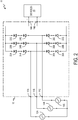
- FIG. 2 is a schematic diagram of AC rectification system 11 including AC voltage sources 12A-12C, fault tolerant rectifier 13, and device(s) 15.
- Fault tolerant rectifier includes inputs 17A-17C; outputs 19A and 19B; and diodes 22A-22C, 24A-24C, 26A-26C, and 28A-28C.
- Diodes 22A-22C, 24A-24C, 26A-26C, and 28A-28C are arranged in series connected pairs.
- Diodes 22A-22C and 24A-24C are paired and provide fault tolerant rectification of AC voltages from inputs 17A-17C to output 19A.
- Diodes 26A-26C and 28A-28C are paired and provide fault tolerant rectification of AC voltages from inputs 17A-17C to output 19B. If any one diode, in a pair of diodes, is shorted or damaged the remaining undamaged diode of the pair of diodes continues to function and provide rectification the corresponding AC voltage. The remaining undamaged diode also limits the current, thus circumventing the need for current limiting resistors as used in current limiting rectifier 14 of FIG. 1 .
- the voltage between outputs 19A and 19B is a rectified voltage that is provided to device(s) 15.
- Device(s) 15 can be a load device and/or a sensor. In one example, device(s) 15 is an AC short detection sensor.
- the output provided by fault tolerant rectifier 13 is a rectified combination of the AC voltages provided by AC voltage sources 12A-12C. When there are no shorts on any electrical branches connected to any of AC voltage sources 12A-12C, the frequency of the output provided by fault tolerant rectifier 13 is six times the frequency of any individual AC voltage provided by any of AC voltage sources 12A-12C.
- AC short detection sensors use a bandpass filter to determine if shorting of an electrical branch has occurred. If the frequency of the rectified signal falls outside of the passband of the bandpass filter, the AC short detection sensor determines that a short of at least one electrical branch has occurred.
- AC rectification system 11 includes three voltage sources and a single rectifier for rectifying the AC voltages.
- AC rectification system 11 comprises a single AC voltage source and a single fault tolerant rectifier for rectifying the AC voltage of the single AC voltage source.
- AC rectification system 11 comprises a plurality of AC voltage sources and a plurality of fault tolerant rectifiers for rectifying each of a plurality of AC voltages.
- FIG. 3 is graph 34 including y-axis 36, x-axis 38, fault tolerant sinewave 40, and current limiting sinewave 42. For purposes of clarity and ease of discussion, graph 34 is discussed with respect to current limiting rectifier 14 of FIG. 1 and fault tolerant rectifier 13 of FIG. 2 .
- Fault tolerant sinewave 40 represents the output of fault tolerant rectifier 13 ( FIG. 2 ).
- Current limiting sinewave 42 represents the output of current limiting rectifier 14 ( FIG. 1 ). As shown, the voltage output by current limiting rectifier 14 is less than the voltage output of fault tolerant rectifier 13.
- Current limiting resistors 16A-16C FIG. 1 ) cause power dissipation and a corresponding voltage drop.
- Fault tolerant rectifier 13 does not include any current limiting resistors, and therefore does not incur the same power dissipation and voltage drop of current limiting rectifier 14.
- sinewave 42 flattens out at the low point of every period.
- the flattened-out portion of sinewave 42 represents the distortion caused by current limiting resistors 16A-16C.
- Rectified AC signals include harmonics which distortion can make difficult to predict.
- the distortion can shift the frequency of sinewave 42 perceived by device(s) 15.
- device(s) 15 is an AC short detection sensor and the perceived frequency shift can move the frequency outside of the passband of the AC short detection sensor, causing false positive fault detection.
- sinewave 40 does not have a flattened out section because there are no current limiting resistors in fault tolerant rectifier 13 to cause distortion. Therefore, fault tolerant rectifier 13 does not cause the false positive fault detection that can be caused by current limiting rectifier 14.
- fault tolerant rectifiers can be used to provide a more ideal output signal for sensitive electronics and/or sensors.
- Using fault tolerant rectifiers as described herein provides an output signal without distortion caused by current limiting resistors. Additionally, fault tolerant rectifiers dissipate less power, making fault tolerant rectifiers more efficient. This lowers the likelihood of false positive short detection and provides a better signal to sensitive electronics and/or sensors.
- a rectifier can comprise a first input configured to receive a first alternating current (AC) voltage; a first output; and a first pair of diodes electrically coupled in series between the first input and the first output, the first pair of diodes configured to rectify the first AC voltage, and wherein the first output is configured to output the first rectified AC voltage.
- AC alternating current
- the rectifier of the preceding paragraph can optionally include, additionally and/or alternatively, any one or more of the following features, configurations and/or additional components:
- a second input can be configured to receive a second AC voltage; and a second pair of diodes can be electrically coupled in series between the second input and the first output, the second pair of diodes can be configured to rectify the second AC voltage, and wherein the first output can be configured to output the first and second rectified AC voltage.
- a third input can be configured to receive a third AC voltage; and a third pair of diodes can be electrically coupled in series between the third input and the first output, the third pair of diodes can be configured to rectify the third AC voltage, and wherein the first output can be further configured to output the first, second, and third rectified AC voltage.
- a second output; and a fourth pair of diodes can be electrically coupled in series between the first input and the second output; and a fifth pair of diodes can be electrically coupled in series between the second input and the second output; and a sixth pair of diodes electrically coupled in series between the third input and the second output.
- the rectifier may not include a resistor electrically coupled between the first input and the first pair of diodes.
- An AC rectification system can comprise a plurality of AC voltage sources configured to provide a plurality of AC voltages; and a plurality of rectifiers of any of the preceding paragrpahs configured to rectify the plurality of AC voltages provided by the plurality of AC voltage sources.
- AC rectification system of the preceding paragraph can optionally include, additionally and/or alternatively, any one or more of the following features, configurations and/or additional components:
- At least one of the plurality of rectifiers can be a full wave rectifier.
- At least one of the plurality of rectifiers can be configured to rectify two or more AC voltages of the plurality of AC voltages provided by the plurality of AC voltage sources.
- the rectifier can be configured to provide full wave rectification to at least three AC voltages provided by the plurality of AC voltage sources.
- a system can comprise a first alternating current (AC) voltage source configured to provide a first AC voltage; a rectifier can comprise a first input configured to receive a first alternating current (AC) voltage; a first output; and a first pair of diodes electrically coupled in series between the first input and the first output, the first pair of diodes configured to rectify the first AC voltage, and wherein the first output is configured to output the first rectified AC voltage.
- AC alternating current
- AC alternating current
- a second AC voltage source can be configured to provide a second AC voltage
- the rectifier can further comprise a second input can be configured to receive a second AC voltage; and a second pair of diodes can be electrically coupled in series between the second input and the first output, the second pair of diodes can be configured to rectify the second AC voltage, and wherein the first output can be configured to output the first and second rectified AC voltage.
- a third AC voltage source can be configured to provide a third AC voltage.
- a third input can be configured to receive the third AC voltage; and a third pair of diodes can be electrically coupled in series between the third input and the first output, the third pair of diodes can be configured to rectify the third AC voltage, and wherein the first output can be further configured to output the third rectified AC voltage.
- a second output; and a fourth pair of diodes can be electrically coupled in series between the first input and the second output; and a fifth pair of diodes can be electrically coupled in series between the second input and the second output; and a sixth pair of diodes can be electrically coupled in series between the third input and the second output.
- the rectifier may not include a resistor electrically coupled between the first input and the first pair of diodes.
- a sensor can be electrically coupled to the first output.
- the sensor can be configured to detect a short of the first and/or second AC voltage sources.
- the system can be a system of an aircraft.
Landscapes
- Engineering & Computer Science (AREA)
- Power Engineering (AREA)
- Rectifiers (AREA)
Applications Claiming Priority (1)
| Application Number | Priority Date | Filing Date | Title |
|---|---|---|---|
| US15/957,014 US20190326828A1 (en) | 2018-04-19 | 2018-04-19 | Fault tolerant ac rectification |
Publications (1)
| Publication Number | Publication Date |
|---|---|
| EP3557748A1 true EP3557748A1 (fr) | 2019-10-23 |
Family
ID=66175192
Family Applications (1)
| Application Number | Title | Priority Date | Filing Date |
|---|---|---|---|
| EP19168859.7A Withdrawn EP3557748A1 (fr) | 2018-04-19 | 2019-04-12 | Redressement de ca à tolérance de pannes |
Country Status (2)
| Country | Link |
|---|---|
| US (1) | US20190326828A1 (fr) |
| EP (1) | EP3557748A1 (fr) |
Families Citing this family (1)
| Publication number | Priority date | Publication date | Assignee | Title |
|---|---|---|---|---|
| EP4210210A1 (fr) | 2022-01-08 | 2023-07-12 | Goodrich Aerospace Services Private Limited | Systèmes et procédés pour le domaine technique de modulation d'impulsions de vecteur spatial |
Citations (6)
| Publication number | Priority date | Publication date | Assignee | Title |
|---|---|---|---|---|
| US5225815A (en) * | 1990-07-11 | 1993-07-06 | Sextant Avionique | Monitor for a polyphase rectifier which detects open diodes by sensing a signal below a predetermined threshold |
| US6538910B1 (en) * | 1999-02-26 | 2003-03-25 | Robert Bosch Gmbh | Rectifier system, preferably for a three-phase generator for motor vehicles |
| EP2026454A1 (fr) * | 2007-08-17 | 2009-02-18 | Siemens Aktiengesellschaft | Redresseur de pont protégé contre les erreurs |
| EP2775597A2 (fr) * | 2013-03-06 | 2014-09-10 | Rockwell Automation Technologies, Inc. | Procédé et appareil de détection de perte de phase et d'ondulation |
| EP2814152A2 (fr) * | 2013-06-14 | 2014-12-17 | Hamilton Sundstrand Corporation | Procédé de dérivation de signaux de courant de commutation dans un redresseur |
| EP2955835A1 (fr) * | 2014-06-12 | 2015-12-16 | Actron Technology Corporation | Circuit de détection de court-circuit et procédé de détection de court-circuit pour redresseur multiphase à domaine de fréquence |
Family Cites Families (3)
| Publication number | Priority date | Publication date | Assignee | Title |
|---|---|---|---|---|
| US8942013B2 (en) * | 2013-02-21 | 2015-01-27 | Pratt & Whitney Canada Corp. | Over voltage protection for electric machines |
| US9543886B2 (en) * | 2014-06-06 | 2017-01-10 | Actron Technology Corporation | Short circuit detection circuit and short circuit detection method for multi-phase rectifier at frequency domain |
| EP3200330B1 (fr) * | 2016-02-01 | 2024-12-25 | Hamilton Sundstrand Corporation | Harmoniques réduites tirés par un redresseur dans un système d'alimentation électrique d'un avion |
-
2018
- 2018-04-19 US US15/957,014 patent/US20190326828A1/en not_active Abandoned
-
2019
- 2019-04-12 EP EP19168859.7A patent/EP3557748A1/fr not_active Withdrawn
Patent Citations (6)
| Publication number | Priority date | Publication date | Assignee | Title |
|---|---|---|---|---|
| US5225815A (en) * | 1990-07-11 | 1993-07-06 | Sextant Avionique | Monitor for a polyphase rectifier which detects open diodes by sensing a signal below a predetermined threshold |
| US6538910B1 (en) * | 1999-02-26 | 2003-03-25 | Robert Bosch Gmbh | Rectifier system, preferably for a three-phase generator for motor vehicles |
| EP2026454A1 (fr) * | 2007-08-17 | 2009-02-18 | Siemens Aktiengesellschaft | Redresseur de pont protégé contre les erreurs |
| EP2775597A2 (fr) * | 2013-03-06 | 2014-09-10 | Rockwell Automation Technologies, Inc. | Procédé et appareil de détection de perte de phase et d'ondulation |
| EP2814152A2 (fr) * | 2013-06-14 | 2014-12-17 | Hamilton Sundstrand Corporation | Procédé de dérivation de signaux de courant de commutation dans un redresseur |
| EP2955835A1 (fr) * | 2014-06-12 | 2015-12-16 | Actron Technology Corporation | Circuit de détection de court-circuit et procédé de détection de court-circuit pour redresseur multiphase à domaine de fréquence |
Also Published As
| Publication number | Publication date |
|---|---|
| US20190326828A1 (en) | 2019-10-24 |
Similar Documents
| Publication | Publication Date | Title |
|---|---|---|
| CN101881794B (zh) | Ac线路信号检测设备和方法以及电源设备 | |
| EP2793340A1 (fr) | Unité de protection contre les surtensions avec des capteurs de courant d'entrée CA | |
| EP2857850B1 (fr) | Détecteur de fuite à la terre HRG et procédé | |
| US9543886B2 (en) | Short circuit detection circuit and short circuit detection method for multi-phase rectifier at frequency domain | |
| KR20210058842A (ko) | 비교기 및 격리된 출력을 갖는 바이너리/디지털 입력 모듈 | |
| US10794938B2 (en) | Voltage detecting circuit | |
| CN105846662A (zh) | 应用于交流电源的保护电路及其相关保护方法 | |
| EP2808194B1 (fr) | Détection de prise desserrée | |
| US10257908B2 (en) | LED device protection circuit and method thereof | |
| EP2574937A2 (fr) | Détecteur de tension de courant alternatif rapide | |
| EP3557748A1 (fr) | Redressement de ca à tolérance de pannes | |
| EP2955835B1 (fr) | Circuit de détection de court-circuit et procédé de détection de court-circuit pour redresseur multiphase à domaine de fréquence | |
| KR102274269B1 (ko) | 쇼트된 다이오드들의 검출 | |
| US20200033385A1 (en) | Dead front connector having a voltage indicator | |
| US9335363B2 (en) | Missing or broken neutral monitoring circuit for split phase electrical distribution configurations | |
| US9853440B2 (en) | Ground detecting apparatus and relay action detecting apparatus | |
| US9692292B2 (en) | Power supply apparatus with alternating current power detection circuit | |
| US20160356824A1 (en) | Loss-phase lack-voltage detection circuit for three-phase input power | |
| EP4293848A1 (fr) | Détection de défaut dans un système de distribution d'énergie fournissant un courant continu haute tension à travers de multiples canaux à masse flottante | |
| CN109991466A (zh) | 检测装置,保护系统及保护方法 | |
| CN105458460B (zh) | 数字逆变焊机及其开机自检方法 | |
| US11677234B2 (en) | Power input source detection in aircraft LRU | |
| US20150048686A1 (en) | Power supply unit | |
| US10444263B2 (en) | Battery monitoring system | |
| US8736248B2 (en) | Detection circuit and a method for detecting a wrong supply voltage |
Legal Events
| Date | Code | Title | Description |
|---|---|---|---|
| PUAI | Public reference made under article 153(3) epc to a published international application that has entered the european phase |
Free format text: ORIGINAL CODE: 0009012 |
|
| STAA | Information on the status of an ep patent application or granted ep patent |
Free format text: STATUS: THE APPLICATION HAS BEEN PUBLISHED |
|
| AK | Designated contracting states |
Kind code of ref document: A1 Designated state(s): AL AT BE BG CH CY CZ DE DK EE ES FI FR GB GR HR HU IE IS IT LI LT LU LV MC MK MT NL NO PL PT RO RS SE SI SK SM TR |
|
| AX | Request for extension of the european patent |
Extension state: BA ME |
|
| STAA | Information on the status of an ep patent application or granted ep patent |
Free format text: STATUS: REQUEST FOR EXAMINATION WAS MADE |
|
| 17P | Request for examination filed |
Effective date: 20191121 |
|
| RBV | Designated contracting states (corrected) |
Designated state(s): AL AT BE BG CH CY CZ DE DK EE ES FI FR GB GR HR HU IE IS IT LI LT LU LV MC MK MT NL NO PL PT RO RS SE SI SK SM TR |
|
| STAA | Information on the status of an ep patent application or granted ep patent |
Free format text: STATUS: THE APPLICATION HAS BEEN WITHDRAWN |
|
| 18W | Application withdrawn |
Effective date: 20201231 |