EP3557694A1 - Antenna device - Google Patents
Antenna device Download PDFInfo
- Publication number
- EP3557694A1 EP3557694A1 EP17880611.3A EP17880611A EP3557694A1 EP 3557694 A1 EP3557694 A1 EP 3557694A1 EP 17880611 A EP17880611 A EP 17880611A EP 3557694 A1 EP3557694 A1 EP 3557694A1
- Authority
- EP
- European Patent Office
- Prior art keywords
- ground conductor
- conductor plate
- antenna device
- vertical portion
- parallel
- Prior art date
- Legal status (The legal status is an assumption and is not a legal conclusion. Google has not performed a legal analysis and makes no representation as to the accuracy of the status listed.)
- Granted
Links
Images


Classifications
-
- H—ELECTRICITY
- H01—ELECTRIC ELEMENTS
- H01Q—ANTENNAS, i.e. RADIO AERIALS
- H01Q1/00—Details of, or arrangements associated with, antennas
- H01Q1/48—Earthing means; Earth screens; Counterpoises
-
- H—ELECTRICITY
- H01—ELECTRIC ELEMENTS
- H01Q—ANTENNAS, i.e. RADIO AERIALS
- H01Q9/00—Electrically-short antennas having dimensions not more than twice the operating wavelength and consisting of conductive active radiating elements
- H01Q9/04—Resonant antennas
- H01Q9/30—Resonant antennas with feed to end of elongated active element, e.g. unipole
-
- H—ELECTRICITY
- H01—ELECTRIC ELEMENTS
- H01Q—ANTENNAS, i.e. RADIO AERIALS
- H01Q9/00—Electrically-short antennas having dimensions not more than twice the operating wavelength and consisting of conductive active radiating elements
- H01Q9/04—Resonant antennas
- H01Q9/30—Resonant antennas with feed to end of elongated active element, e.g. unipole
- H01Q9/42—Resonant antennas with feed to end of elongated active element, e.g. unipole with folded element, the folded parts being spaced apart a small fraction of the operating wavelength
Definitions
- the present invention relates to an antenna device having a feeding point at a position that is distant from an outer periphery of a ground conductor plate to a center side of the ground conductor plate.
- Patent Document 1 JP-2006-140667-A
- antenna devices having a feeding point at a position that is distant from an outer periphery of a ground conductor plate to its center side have a problem that they can basically correspond only to polarized waves in a direction perpendicular to the ground conductor plate.
- the present invention has been made in the above circumstances, and an object of the invention is to provide an antenna device that has a configuration in which a feeding point is located at a position that is distant from an outer periphery of a ground conductor plate to a center side and that would correspond to polarized waves in a direction parallel to the ground conductor plate.
- the antenna device includes a ground conductor plate and an antenna element, the antenna element includes:
- a maximum voltage point of the antenna element may be located in the along-edge portion.
- the along-edge portion may have a bent portion that is bent along a corner portion of the ground conductor plate when viewed from the direction perpendicular to the ground conductor plate.
- the along-edge portion may be longer than or equal to a half of an entire length of the antenna element.
- the feeding point may be located in a virtual area whose center is common to a center of the ground conductor plate and that is formed so as to have an area that is 1/2 of an area of the ground conductor plate by reducing the ground conductor plate by a same factor in longitudinal and lateral directions.
- the other end of the second vertical portion may be connected to a portion in a vicinity of a peripheral edge of the ground conductor plate.
- At least a part of the along-edge portion may be located at a position that is closer to the ground conductor plate than the one ends of the first vertical portion and the second vertical portion.
- a desired combination of the above constituent elements and a method, a system, etc. obtained by converting an expression of the present invention are also effective as other aspects of the present invention.
- the present invention would provide an antenna device that has a configuration in which a feeding point is located at a position that is distant from an outer periphery of a ground conductor plate to a center side and that would corresponds to polarized waves in a direction parallel to the ground conductor plate.
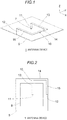
- Fig. 1 is a schematic perspective view of an antenna device 1 according to a first embodiment of the present invention. Three orthogonal axes, that is, X, Y, and Z axes, are defined as shown in Fig. 1.
- Fig. 2 is a schematic plan view of the antenna device 1.
- the antenna device 1 has sending/receiving target frequency ranges 699 to 960 MHz and 1,710 to 2,690 MHz.
- the antenna device 1 includes a ground conductor plate 5 and an antenna element 10.
- the ground conductor plate 5 is a flat plate that is parallel to the XY plane and functions as a ground of the antenna element 10.
- the ground conductor plate 5 may be a metal plate or a substrate on at least one of whose surfaces a ground pattern is formed. Each of sides of the ground conductor plate 5 is parallel to the X direction or the Y direction.
- the antenna element 10 is made of a conductor and includes a first vertical portion 11, a second vertical portion 12, a first parallel portion 13, a second parallel portion 14, and a third parallel portion 15.
- the first vertical portion 11 and the second vertical portion 12 are erected substantially vertically (in the +Z direction) from the ground conductor plate 5.
- An end portion, in the -Z direction, of the first vertical portion 11 serves as a feeding point 7 and is located at a position that is distant from a periphery of the ground conductor plate 5 to a center side, for example, in a virtual area 8 (see Fig.
- the second vertical portion 12 is connected (grounded) to a portion in a vicinity of a peripheral edge of the ground conductor plate 5.
- the first vertical portion 11 and the second vertical portion 12 are located at the same position in the X direction.
- the first parallel portion 13, the second parallel portion 14, and the third parallel portion 15 are substantially parallel to the ground conductor plate 5 and constitute a connecting portion that connects respective end portions, in the +Z direction, of the first vertical portion 11 and the second vertical portion 12 to each other.
- the first parallel portion 13 extends in the +X direction from the end portion, in the +Z direction, of the first vertical portion 11 and reaches a position where it shares the same X and Y coordinates with the outer periphery of the ground conductor plate 5.
- the second parallel portion 14 and the third parallel portion 15 constitute an along-edge portion that extends along the outer periphery of the ground conductor plate 5 when viewed from the +Z direction.
- the second parallel portion 14 extends in the -Y direction from an end portion, in the +X direction, of the first parallel portion 13 parallel to the outer periphery of the ground conductor plate 5 and reaches a position where it shares the same X and Y coordinates with a corner of the ground conductor plate 5.
- the third parallel portion 15 extends in the -X direction from an end portion, in the -Y direction, of the second parallel portion 14 parallel to the outer periphery of the ground conductor plate 5 and reaches the end portion, in the +Z direction, of the second vertical portion 12.
- a bent portion at the boundary between the second parallel portion 14 and the third parallel portion 15 is bent along the corner portion of the ground conductor plate 5 when viewed from the +Z direction.
- a portion around the center of the second parallel portion 14 is a maximum voltage point of the antenna element 10.
- a total length of the second parallel portion 14 and the third parallel portion 15 (the length of the along-edge portion) is greater than or equal to half of the entire length of the antenna element 10.
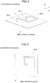
- Fig. 3 is a schematic perspective view of an antenna device 800 of Comparative Example.
- Fig. 4 is a schematic plan view of the antenna device 800.
- an end portion, in the -Z direction, of a first vertical portion 811 is located at the center of a ground conductor plate 5 and serves as a feeding point 7.
- a parallel portion 813, parallel to the ground conductor plate 5, of the antenna element is located inside the outer periphery of the ground conductor plate 5 and does not have a portion that extends along the outer periphery of the ground conductor plate 5 when viewed from the +Z direction.
- An end portion (grounding portion), in the -Z direction, of a second vertical portion 812 is located at a position that is distant from the outer periphery of the ground conductor plate 5.
- Fig. 5 is a diagram of respective directivity characteristics, at 800 MHz, in the XY plane, of polarized waves in a direction parallel to the XY plane of the antenna device 1 according to the first embodiment and the antenna device 800 of Comparative Example.
- the directivity characteristic in the XY plane i.e., the directivity characteristic in the directions parallel to the ground conductor plate 5
- the polarized waves in the direction parallel to the XY plane of the antenna device 1 according to the first embodiment is better than that of the antenna device 800 of Comparative Example in all directions.
- An average directivity gain in the XY plane is -3.48 dBi in the antenna device 1 according to the first embodiment and -7.33 dBi in the antenna device 800 of Comparative Example.
- the average directivity gain of the antenna device 1 according to the first embodiment is larger by about 3.8 dBi.
- Fig. 6 is a diagram of respective directivity characteristics, at 800 MHz, in the XZ plane, of the polarized waves in the direction parallel to the XY plane of the antenna device 1 according to the first embodiment and the antenna device 800 of Comparative Example.
- the directivity characteristic in the XZ plane i.e., the directivity characteristic in the directions perpendicular to the ground conductor plate 5
- the directivity characteristic in the XY plane is better than that of the antenna device 800 of Comparative Example in all directions.
- An average directivity gain in the XZ plane is -1.15 dBi in the antenna device 1 according to the first embodiment and -3.57 dBi in the antenna device 800 of Comparative Example.
- the average directivity gain of the antenna device 1 according to the first embodiment is larger by about 2.4 dBi.
- the embodiment would provide the following advantages.
- Fig. 7 is a schematic perspective view of an antenna device 2 according to a second embodiment of the invention.
- Fig. 8 is a schematic plan view of the antenna device 2.
- the antenna device 2 according to the embodiment is different from the antenna device 1 according to the first embodiment in that tongue pieces 14a and 15a project from the second parallel portion 14 and the third parallel portion 15, respectively, and is the same as the antenna device 1 according to the first embodiment in the other points.
- the tongue piece 14a projects in the -Z direction (i.e., toward the ground conductor plate 5) from an outer peripheral edge that is located on the +X direction and extends in a range having a predetermined length and including the end, in the -Y direction, of the second parallel portion 14, and is not in contact with the ground conductor plate 5.
- the tongue piece 15a projects in the -Z direction (i.e., toward the ground conductor plate 5) from an outer peripheral edge that is located on the -Y direction and extends in a range having a predetermined length and including the end, in the +X direction, of the third parallel portion 15, and is not in contact with the ground conductor plate 5.
- the side, on the -Y direction, of the tongue piece 14a and the side, on the +X direction, of the tongue piece 15a may be in contact with or may be separate from each other. According to the embodiment, by virtue of the formation of the tongue pieces 14a and 15a, the directivity gain of polarized waves in the direction parallel to the ground conductor plate 5 would be increased further.
Landscapes
- Variable-Direction Aerials And Aerial Arrays (AREA)
- Details Of Aerials (AREA)
- Waveguide Aerials (AREA)
Abstract
Description
- The present invention relates to an antenna device having a feeding point at a position that is distant from an outer periphery of a ground conductor plate to a center side of the ground conductor plate.
- Although sending/receiving vertically polarized waves have been the mainstream in conventional wireless communication, sending/receiving horizontally polarized waves have also recently become necessary, for example, in LTE (Long Term Evolution).
- Patent Document 1:
JP-2006-140667-A - Whereas in an antenna device of Patent Document 1 a feeding point is located at a peripheral position on a substrate, antenna devices having a feeding point at a position that is distant from an outer periphery of a ground conductor plate to its center side have a problem that they can basically correspond only to polarized waves in a direction perpendicular to the ground conductor plate.
- The present invention has been made in the above circumstances, and an object of the invention is to provide an antenna device that has a configuration in which a feeding point is located at a position that is distant from an outer periphery of a ground conductor plate to a center side and that would correspond to polarized waves in a direction parallel to the ground conductor plate.
- One aspect of the present invention is an antenna device. The antenna device includes a ground conductor plate and an antenna element,
the antenna element includes: - a first vertical portion and a second vertical portion which are erected substantially perpendicularly from the ground conductor plate; and
- a connecting portion which has a portion extending substantially parallel to the ground conductor plate and which connects one end of the first vertical portion and one end of the second vertical portion to each other,
- A maximum voltage point of the antenna element may be located in the along-edge portion.
- The along-edge portion may have a bent portion that is bent along a corner portion of the ground conductor plate when viewed from the direction perpendicular to the ground conductor plate.
- The along-edge portion may be longer than or equal to a half of an entire length of the antenna element.
- The feeding point may be located in a virtual area whose center is common to a center of the ground conductor plate and that is formed so as to have an area that is 1/2 of an area of the ground conductor plate by reducing the ground conductor plate by a same factor in longitudinal and lateral directions.
- The other end of the second vertical portion may be connected to a portion in a vicinity of a peripheral edge of the ground conductor plate.
- At least a part of the along-edge portion may be located at a position that is closer to the ground conductor plate than the one ends of the first vertical portion and the second vertical portion.
- A desired combination of the above constituent elements and a method, a system, etc. obtained by converting an expression of the present invention are also effective as other aspects of the present invention.
- The present invention would provide an antenna device that has a configuration in which a feeding point is located at a position that is distant from an outer periphery of a ground conductor plate to a center side and that would corresponds to polarized waves in a direction parallel to the ground conductor plate.
-
-
Fig. 1 is a schematic perspective view of anantenna device 1 according to a first embodiment of the present invention. -
Fig. 2 is a schematic plan view of theantenna device 1. -
Fig. 3 is a schematic perspective view of anantenna device 800 of Comparative Example. -
Fig. 4 is a schematic plan view of theantenna device 800. -
Fig. 5 is a diagram of respective directivity characteristics, at 800 MHz, in the XY plane, of polarized waves in a direction parallel to the XY plane of theantenna device 1 according to the first embodiment and theantenna device 800 of Comparative Example. -
Fig. 6 is a diagram of respective directivity characteristics, at 800 MHz, in the XZ plane, of polarized waves in the direction parallel to the XY plane of theantenna device 1 according to the first embodiment and theantenna device 800 of Comparative Example. -
Fig. 7 is a schematic perspective view of anantenna device 2 according to a second embodiment of the present invention. -
Fig. 8 is a schematic plan view of theantenna device 2. - Preferred embodiments of the invention will be hereinafter described in detail with reference to the drawings. The same or equivalent constituent elements, members, or the like shown in the drawings are given the same symbol and redundant descriptions therefor will be omitted as appropriate. The embodiments are not intended to limit the invention and are just examples, and all features described in the embodiments and combinations thereof are not always essential to the invention.
-
Fig. 1 is a schematic perspective view of anantenna device 1 according to a first embodiment of the present invention. Three orthogonal axes, that is, X, Y, and Z axes, are defined as shown inFig. 1. Fig. 2 is a schematic plan view of theantenna device 1. Theantenna device 1 has sending/receiving target frequency ranges 699 to 960 MHz and 1,710 to 2,690 MHz. Theantenna device 1 includes aground conductor plate 5 and anantenna element 10. Theground conductor plate 5 is a flat plate that is parallel to the XY plane and functions as a ground of theantenna element 10. Theground conductor plate 5 may be a metal plate or a substrate on at least one of whose surfaces a ground pattern is formed. Each of sides of theground conductor plate 5 is parallel to the X direction or the Y direction. - The
antenna element 10 is made of a conductor and includes a firstvertical portion 11, a secondvertical portion 12, a firstparallel portion 13, a secondparallel portion 14, and a thirdparallel portion 15. The firstvertical portion 11 and the secondvertical portion 12 are erected substantially vertically (in the +Z direction) from theground conductor plate 5. An end portion, in the -Z direction, of the firstvertical portion 11 serves as afeeding point 7 and is located at a position that is distant from a periphery of theground conductor plate 5 to a center side, for example, in a virtual area 8 (seeFig. 2 ) whose center is common to a center of theground conductor plate 5 and whose area is 1/2 of an area of theground conductor plate 5; that is, thevirtual area 8 is formed by reducing theground conductor plate 5 by thesame factor 
vertical portion 12 is connected (grounded) to a portion in a vicinity of a peripheral edge of theground conductor plate 5. The firstvertical portion 11 and the secondvertical portion 12 are located at the same position in the X direction. - The first
parallel portion 13, the secondparallel portion 14, and the thirdparallel portion 15 are substantially parallel to theground conductor plate 5 and constitute a connecting portion that connects respective end portions, in the +Z direction, of the firstvertical portion 11 and the secondvertical portion 12 to each other. The firstparallel portion 13 extends in the +X direction from the end portion, in the +Z direction, of the firstvertical portion 11 and reaches a position where it shares the same X and Y coordinates with the outer periphery of theground conductor plate 5. The secondparallel portion 14 and the thirdparallel portion 15 constitute an along-edge portion that extends along the outer periphery of theground conductor plate 5 when viewed from the +Z direction. The secondparallel portion 14 extends in the -Y direction from an end portion, in the +X direction, of the firstparallel portion 13 parallel to the outer periphery of theground conductor plate 5 and reaches a position where it shares the same X and Y coordinates with a corner of theground conductor plate 5. The thirdparallel portion 15 extends in the -X direction from an end portion, in the -Y direction, of the secondparallel portion 14 parallel to the outer periphery of theground conductor plate 5 and reaches the end portion, in the +Z direction, of the secondvertical portion 12. A bent portion at the boundary between the secondparallel portion 14 and the thirdparallel portion 15 is bent along the corner portion of theground conductor plate 5 when viewed from the +Z direction. A portion around the center of the secondparallel portion 14 is a maximum voltage point of theantenna element 10. A total length of the secondparallel portion 14 and the third parallel portion 15 (the length of the along-edge portion) is greater than or equal to half of the entire length of theantenna element 10. -
Fig. 3 is a schematic perspective view of anantenna device 800 of Comparative Example.Fig. 4 is a schematic plan view of theantenna device 800. In theantenna device 800, as in the first embodiment, an end portion, in the -Z direction, of a firstvertical portion 811 is located at the center of aground conductor plate 5 and serves as afeeding point 7. On the other hand, unlike in the first embodiment, aparallel portion 813, parallel to theground conductor plate 5, of the antenna element is located inside the outer periphery of theground conductor plate 5 and does not have a portion that extends along the outer periphery of theground conductor plate 5 when viewed from the +Z direction. An end portion (grounding portion), in the -Z direction, of a secondvertical portion 812 is located at a position that is distant from the outer periphery of theground conductor plate 5. -
Fig. 5 is a diagram of respective directivity characteristics, at 800 MHz, in the XY plane, of polarized waves in a direction parallel to the XY plane of theantenna device 1 according to the first embodiment and theantenna device 800 of Comparative Example. As seen fromFig. 5 , the directivity characteristic in the XY plane (i.e., the directivity characteristic in the directions parallel to the ground conductor plate 5) of the polarized waves in the direction parallel to the XY plane of theantenna device 1 according to the first embodiment is better than that of theantenna device 800 of Comparative Example in all directions. An average directivity gain in the XY plane is -3.48 dBi in theantenna device 1 according to the first embodiment and -7.33 dBi in theantenna device 800 of Comparative Example. The average directivity gain of theantenna device 1 according to the first embodiment is larger by about 3.8 dBi. -
Fig. 6 is a diagram of respective directivity characteristics, at 800 MHz, in the XZ plane, of the polarized waves in the direction parallel to the XY plane of theantenna device 1 according to the first embodiment and theantenna device 800 of Comparative Example. As seen fromFig. 6 , the directivity characteristic in the XZ plane (i.e., the directivity characteristic in the directions perpendicular to the ground conductor plate 5) of the polarized waves in the direction parallel to the XY plane of theantenna device 1 according to the first embodiment is better than that of theantenna device 800 of Comparative Example in all directions. An average directivity gain in the XZ plane is -1.15 dBi in theantenna device 1 according to the first embodiment and -3.57 dBi in theantenna device 800 of Comparative Example. The average directivity gain of theantenna device 1 according to the first embodiment is larger by about 2.4 dBi. - The embodiment would provide the following advantages.
- (1) Since the second
parallel portion 14 and the thirdparallel portion 15 of theantenna element 10 extend along the outer periphery of theground conductor plate 5 when viewed from the direction perpendicular to theground conductor plate 5, it is possible to correspond to the polarized waves in the direction parallel to the ground conductor plate 5 (i.e., to increase the directivity gain of the polarized waves in the direction parallel to the ground conductor plate 5) though theantenna element 10 is configured in such a manner that thefeeding point 7, that is, the end portion, in the -Z direction, of the firstvertical portion 11, is distant from the outer periphery to the center side (e.g., thefeeding point 7 is located around the center of the ground conductor plate 5). - (2) Since the maximum voltage point of the
antenna element 10 is located at a position along the outer periphery of theground conductor plate 5 when viewed from the direction perpendicular to theground conductor plate 5, an effect of increasing the directivity gain of the polarized waves in the direction parallel to theground conductor plate 5 is large. - (3) Since the bent portion at the boundary between the second
parallel portion 14 and the thirdparallel portion 15 of theantenna element 10 is bent along the corner portion of theground conductor plate 5 when viewed from the +Z direction, an effect of increasing the directivity gain of the polarized waves in the direction parallel to theground conductor plate 5 is large. - (4) Since the end portion, in the -Z direction, of the second
vertical portion 12 of theantenna element 10 is connected (grounded) to the portion in the vicinity of the peripheral edge of theground conductor plate 5, an effect of increasing the directivity gain of the polarized waves in the direction parallel to theground conductor plate 5 is large. -
Fig. 7 is a schematic perspective view of anantenna device 2 according to a second embodiment of the invention.Fig. 8 is a schematic plan view of theantenna device 2. Theantenna device 2 according to the embodiment is different from theantenna device 1 according to the first embodiment in thattongue pieces parallel portion 14 and the thirdparallel portion 15, respectively, and is the same as theantenna device 1 according to the first embodiment in the other points. Thetongue piece 14a projects in the -Z direction (i.e., toward the ground conductor plate 5) from an outer peripheral edge that is located on the +X direction and extends in a range having a predetermined length and including the end, in the -Y direction, of the secondparallel portion 14, and is not in contact with theground conductor plate 5. Thetongue piece 15a projects in the -Z direction (i.e., toward the ground conductor plate 5) from an outer peripheral edge that is located on the -Y direction and extends in a range having a predetermined length and including the end, in the +X direction, of the thirdparallel portion 15, and is not in contact with theground conductor plate 5. The side, on the -Y direction, of thetongue piece 14a and the side, on the +X direction, of thetongue piece 15a may be in contact with or may be separate from each other. According to the embodiment, by virtue of the formation of thetongue pieces ground conductor plate 5 would be increased further. - Although the present invention has been described above by way of the embodiments, it would be understood by those skilled in the art that each constituent element and treatment or working process of the embodiments would be modified in various manners within a scope of the claims.
- 1, 2: Antenna device; 5: Ground conductor plate; 7: Feeding point; 8: Virtual area; 10: Antenna element; 11: First vertical portion; 12: Second vertical portion; 13: First parallel portion; 14: Second parallel portion; 14a: Tongue portion; 15: Third parallel portion; 15a: Tongue portion; 800: Antenna device; 811: First vertical portion; 812: Second vertical portion; 813: Parallel portion.
the other end of the second vertical portion is grounded, and
the connecting portion has an along-edge portion which extends along the outer periphery of the ground conductor plate when viewed from a direction perpendicular to the ground conductor plate.
Claims (7)
- An antenna device comprising a ground conductor plate and an antenna element,
wherein the antenna element includes:a first vertical portion and a second vertical portion which are erected substantially perpendicularly from the ground conductor plate; anda connecting portion which includes a portion extending substantially parallel to the ground conductor plate and which connects one end of the first vertical portion and one end of the second vertical portion to each other,wherein the other end of the first vertical portion serves as a feeding point and is located at a position that is distant from an outer periphery of the ground conductor plate to a center side of the ground conductor plate,
wherein the other end of the second vertical portion is grounded, and
wherein the connecting portion includes an along-edge portion which extends along the outer periphery of the ground conductor plate when viewed from a direction perpendicular to the ground conductor plate. - The antenna device according to claim 1, wherein a maximum voltage point of the antenna element is located in the along-edge portion.
- The antenna device according to claim 1 or 2, wherein the along-edge portion includes a bent portion that is bent along a corner portion of the ground conductor plate when viewed from the direction perpendicular to the ground conductor plate.
- The antenna device according to any one of claims 1 to 3, wherein the along-edge portion is longer than or equal to a half of an entire length of the antenna element.
- The antenna device according to any one of claims 1 to 4, wherein the feeding point is located within a virtual area whose center is common to a center of the ground conductor plate and which is formed so as to have an area that is 1/2 of an area of the ground conductor plate by reducing the ground conductor plate by a same factor in longitudinal and lateral directions.
- The antenna device according to any one of claims 1 to 5, wherein the other end of the second vertical portion is connected to a portion in a vicinity of a peripheral edge of the ground conductor plate.
- The antenna device according to any one of claims 1 to 6, wherein at least a part of the along-edge portion is located at a position that is closer to the ground conductor plate than the one end of the first vertical portion and the one end of the second vertical portion.
Applications Claiming Priority (2)
| Application Number | Priority Date | Filing Date | Title |
|---|---|---|---|
| JP2016244805 | 2016-12-16 | ||
| PCT/JP2017/040301 WO2018110162A1 (en) | 2016-12-16 | 2017-11-08 | Antenna device |
Publications (3)
| Publication Number | Publication Date |
|---|---|
| EP3557694A1 true EP3557694A1 (en) | 2019-10-23 |
| EP3557694A4 EP3557694A4 (en) | 2020-07-29 |
| EP3557694B1 EP3557694B1 (en) | 2022-09-28 |
Family
ID=62558576
Family Applications (1)
| Application Number | Title | Priority Date | Filing Date |
|---|---|---|---|
| EP17880611.3A Active EP3557694B1 (en) | 2016-12-16 | 2017-11-08 | Antenna device |
Country Status (5)
| Country | Link |
|---|---|
| US (1) | US10950930B2 (en) |
| EP (1) | EP3557694B1 (en) |
| JP (1) | JP6971256B2 (en) |
| CN (1) | CN109983622B (en) |
| WO (1) | WO2018110162A1 (en) |
Families Citing this family (2)
| Publication number | Priority date | Publication date | Assignee | Title |
|---|---|---|---|---|
| DE112021006900B4 (en) * | 2021-04-01 | 2024-10-17 | Mitsubishi Electric Corporation | ANTENNA DEVICE |
| WO2023068007A1 (en) * | 2021-10-22 | 2023-04-27 | 株式会社ヨコオ | Antenna device |
Family Cites Families (18)
| Publication number | Priority date | Publication date | Assignee | Title |
|---|---|---|---|---|
| GB9508891D0 (en) * | 1995-05-02 | 1995-06-21 | Centrepoint Technology Limited | Antenna unit |
| JP4064889B2 (en) * | 2003-07-16 | 2008-03-19 | 株式会社日本自動車部品総合研究所 | Compound antenna device |
| JP3805772B2 (en) | 2004-01-13 | 2006-08-09 | 株式会社東芝 | ANTENNA DEVICE AND PORTABLE RADIO COMMUNICATION DEVICE |
| CN2738415Y (en) | 2004-08-19 | 2005-11-02 | 上海航天测控通信研究所 | Lateral folding element antenna |
| JP2006140667A (en) | 2004-11-11 | 2006-06-01 | Yokowo Co Ltd | Antenna system |
| JP4382683B2 (en) * | 2005-02-09 | 2009-12-16 | 株式会社デンソー | Integrated antenna device |
| JP4690820B2 (en) * | 2005-08-08 | 2011-06-01 | 古河電気工業株式会社 | Antenna device |
| JP4389863B2 (en) | 2005-10-25 | 2009-12-24 | 株式会社デンソー | Integrated antenna |
| JP4714876B2 (en) * | 2006-08-10 | 2011-06-29 | 独立行政法人情報通信研究機構 | antenna |
| KR101129997B1 (en) * | 2006-08-24 | 2012-03-26 | 야기안테나 가부시기가이샤 | Antenna device |
| US8525736B2 (en) | 2007-07-05 | 2013-09-03 | Mitsubishi Cable Industries, Ltd. | Antenna device |
| JP2010278750A (en) * | 2009-05-28 | 2010-12-09 | Panasonic Corp | Portable radio |
| GB201100617D0 (en) * | 2011-01-14 | 2011-03-02 | Antenova Ltd | Dual antenna structure having circular polarisation characteristics |
| TWM432153U (en) * | 2011-11-11 | 2012-06-21 | Cipherlab Co Ltd | Dual polarized antenna |
| TWM463913U (en) | 2012-07-05 | 2013-10-21 | Ralink Technology Corp | Antenna structure |
| JP6167745B2 (en) * | 2013-08-13 | 2017-07-26 | 富士通株式会社 | Antenna device |
| US11023882B2 (en) * | 2018-03-20 | 2021-06-01 | Edge Mobile Payments Llc | Method and apparatus for completing credit card transactions from an MST and NFC capable module affixed to a smart phone, a mobile wallet, a personal digital assistant or the cases for same |
| JP6341399B1 (en) * | 2018-03-14 | 2018-06-13 | パナソニックIpマネジメント株式会社 | Antenna device |
-
2017
- 2017-11-08 WO PCT/JP2017/040301 patent/WO2018110162A1/en not_active Ceased
- 2017-11-08 CN CN201780071891.1A patent/CN109983622B/en active Active
- 2017-11-08 US US16/347,594 patent/US10950930B2/en active Active
- 2017-11-08 JP JP2018556259A patent/JP6971256B2/en active Active
- 2017-11-08 EP EP17880611.3A patent/EP3557694B1/en active Active
Also Published As
| Publication number | Publication date |
|---|---|
| JP6971256B2 (en) | 2021-11-24 |
| US10950930B2 (en) | 2021-03-16 |
| CN109983622B (en) | 2021-10-08 |
| EP3557694A4 (en) | 2020-07-29 |
| CN109983622A (en) | 2019-07-05 |
| US20190267706A1 (en) | 2019-08-29 |
| WO2018110162A1 (en) | 2018-06-21 |
| JPWO2018110162A1 (en) | 2019-10-24 |
| EP3557694B1 (en) | 2022-09-28 |
Similar Documents
| Publication | Publication Date | Title |
|---|---|---|
| JP6298104B2 (en) | All-metal backshell antenna system | |
| US10283847B2 (en) | Antenna device and mobile device | |
| EP3322030A1 (en) | Antenna apparatus and mobile terminal | |
| EP3471208A1 (en) | Dual band antenna module | |
| EP2975691B1 (en) | Antenna device | |
| US9960485B2 (en) | Antenna device using EBG structure, wireless communication device, and radar device | |
| EP3032645A1 (en) | An assembly of circuit boards and electronic device comprising said assembly | |
| CN106549216A (en) | High-isolation multi-antenna structure | |
| EP3090466B1 (en) | Dipole fixation in antenna system | |
| US20140071014A1 (en) | Multi-band antenna | |
| US10950930B2 (en) | Antenna device | |
| JP5933631B2 (en) | Antenna assembly | |
| US10283867B2 (en) | Square shaped multi-slotted 2.45 GHz wearable antenna | |
| EP3370305A1 (en) | Antenna device | |
| US9722307B2 (en) | Terminal antenna structure and terminal | |
| CN104377445A (en) | Double-antenna structure | |
| CN103378414A (en) | Multi-aerial system | |
| US10637126B2 (en) | Antenna and electric device using the same | |
| JP4655095B2 (en) | Antenna device | |
| TW201703347A (en) | Printed multi-band antenna | |
| CN205429167U (en) | Antenna device | |
| US11476570B2 (en) | Antenna apparatus | |
| EP3065216A1 (en) | Monopole antenna | |
| US10411360B2 (en) | Planar antenna | |
| CN105826682B (en) | Mimo antenna |
Legal Events
| Date | Code | Title | Description |
|---|---|---|---|
| STAA | Information on the status of an ep patent application or granted ep patent |
Free format text: STATUS: THE INTERNATIONAL PUBLICATION HAS BEEN MADE |
|
| PUAI | Public reference made under article 153(3) epc to a published international application that has entered the european phase |
Free format text: ORIGINAL CODE: 0009012 |
|
| STAA | Information on the status of an ep patent application or granted ep patent |
Free format text: STATUS: REQUEST FOR EXAMINATION WAS MADE |
|
| 17P | Request for examination filed |
Effective date: 20190425 |
|
| AK | Designated contracting states |
Kind code of ref document: A1 Designated state(s): AL AT BE BG CH CY CZ DE DK EE ES FI FR GB GR HR HU IE IS IT LI LT LU LV MC MK MT NL NO PL PT RO RS SE SI SK SM TR |
|
| AX | Request for extension of the european patent |
Extension state: BA ME |
|
| DAV | Request for validation of the european patent (deleted) | ||
| DAX | Request for extension of the european patent (deleted) | ||
| A4 | Supplementary search report drawn up and despatched |
Effective date: 20200701 |
|
| RIC1 | Information provided on ipc code assigned before grant |
Ipc: H01Q 9/42 20060101ALI20200625BHEP Ipc: H01Q 9/30 20060101AFI20200625BHEP |
|
| REG | Reference to a national code |
Ref country code: DE Ref legal event code: R079 Ref document number: 602017062266 Country of ref document: DE Free format text: PREVIOUS MAIN CLASS: H01Q0009300000 Ipc: H01Q0009420000 |
|
| GRAP | Despatch of communication of intention to grant a patent |
Free format text: ORIGINAL CODE: EPIDOSNIGR1 |
|
| STAA | Information on the status of an ep patent application or granted ep patent |
Free format text: STATUS: GRANT OF PATENT IS INTENDED |
|
| RIC1 | Information provided on ipc code assigned before grant |
Ipc: H01Q 9/42 20060101AFI20220404BHEP |
|
| INTG | Intention to grant announced |
Effective date: 20220511 |
|
| GRAS | Grant fee paid |
Free format text: ORIGINAL CODE: EPIDOSNIGR3 |
|
| GRAA | (expected) grant |
Free format text: ORIGINAL CODE: 0009210 |
|
| STAA | Information on the status of an ep patent application or granted ep patent |
Free format text: STATUS: THE PATENT HAS BEEN GRANTED |
|
| AK | Designated contracting states |
Kind code of ref document: B1 Designated state(s): AL AT BE BG CH CY CZ DE DK EE ES FI FR GB GR HR HU IE IS IT LI LT LU LV MC MK MT NL NO PL PT RO RS SE SI SK SM TR |
|
| REG | Reference to a national code |
Ref country code: GB Ref legal event code: FG4D |
|
| REG | Reference to a national code |
Ref country code: CH Ref legal event code: EP |
|
| REG | Reference to a national code |
Ref country code: DE Ref legal event code: R096 Ref document number: 602017062266 Country of ref document: DE |
|
| REG | Reference to a national code |
Ref country code: AT Ref legal event code: REF Ref document number: 1521865 Country of ref document: AT Kind code of ref document: T Effective date: 20221015 |
|
| REG | Reference to a national code |
Ref country code: IE Ref legal event code: FG4D |
|
| REG | Reference to a national code |
Ref country code: LT Ref legal event code: MG9D |
|
| PG25 | Lapsed in a contracting state [announced via postgrant information from national office to epo] |
Ref country code: SE Free format text: LAPSE BECAUSE OF FAILURE TO SUBMIT A TRANSLATION OF THE DESCRIPTION OR TO PAY THE FEE WITHIN THE PRESCRIBED TIME-LIMIT Effective date: 20220928 Ref country code: RS Free format text: LAPSE BECAUSE OF FAILURE TO SUBMIT A TRANSLATION OF THE DESCRIPTION OR TO PAY THE FEE WITHIN THE PRESCRIBED TIME-LIMIT Effective date: 20220928 Ref country code: NO Free format text: LAPSE BECAUSE OF FAILURE TO SUBMIT A TRANSLATION OF THE DESCRIPTION OR TO PAY THE FEE WITHIN THE PRESCRIBED TIME-LIMIT Effective date: 20221228 Ref country code: LV Free format text: LAPSE BECAUSE OF FAILURE TO SUBMIT A TRANSLATION OF THE DESCRIPTION OR TO PAY THE FEE WITHIN THE PRESCRIBED TIME-LIMIT Effective date: 20220928 Ref country code: LT Free format text: LAPSE BECAUSE OF FAILURE TO SUBMIT A TRANSLATION OF THE DESCRIPTION OR TO PAY THE FEE WITHIN THE PRESCRIBED TIME-LIMIT Effective date: 20220928 Ref country code: FI Free format text: LAPSE BECAUSE OF FAILURE TO SUBMIT A TRANSLATION OF THE DESCRIPTION OR TO PAY THE FEE WITHIN THE PRESCRIBED TIME-LIMIT Effective date: 20220928 |
|
| REG | Reference to a national code |
Ref country code: NL Ref legal event code: MP Effective date: 20220928 |
|
| REG | Reference to a national code |
Ref country code: AT Ref legal event code: MK05 Ref document number: 1521865 Country of ref document: AT Kind code of ref document: T Effective date: 20220928 |
|
| PG25 | Lapsed in a contracting state [announced via postgrant information from national office to epo] |
Ref country code: HR Free format text: LAPSE BECAUSE OF FAILURE TO SUBMIT A TRANSLATION OF THE DESCRIPTION OR TO PAY THE FEE WITHIN THE PRESCRIBED TIME-LIMIT Effective date: 20220928 Ref country code: GR Free format text: LAPSE BECAUSE OF FAILURE TO SUBMIT A TRANSLATION OF THE DESCRIPTION OR TO PAY THE FEE WITHIN THE PRESCRIBED TIME-LIMIT Effective date: 20221229 |
|
| PG25 | Lapsed in a contracting state [announced via postgrant information from national office to epo] |
Ref country code: SM Free format text: LAPSE BECAUSE OF FAILURE TO SUBMIT A TRANSLATION OF THE DESCRIPTION OR TO PAY THE FEE WITHIN THE PRESCRIBED TIME-LIMIT Effective date: 20220928 Ref country code: RO Free format text: LAPSE BECAUSE OF FAILURE TO SUBMIT A TRANSLATION OF THE DESCRIPTION OR TO PAY THE FEE WITHIN THE PRESCRIBED TIME-LIMIT Effective date: 20220928 Ref country code: PT Free format text: LAPSE BECAUSE OF FAILURE TO SUBMIT A TRANSLATION OF THE DESCRIPTION OR TO PAY THE FEE WITHIN THE PRESCRIBED TIME-LIMIT Effective date: 20230130 Ref country code: ES Free format text: LAPSE BECAUSE OF FAILURE TO SUBMIT A TRANSLATION OF THE DESCRIPTION OR TO PAY THE FEE WITHIN THE PRESCRIBED TIME-LIMIT Effective date: 20220928 Ref country code: CZ Free format text: LAPSE BECAUSE OF FAILURE TO SUBMIT A TRANSLATION OF THE DESCRIPTION OR TO PAY THE FEE WITHIN THE PRESCRIBED TIME-LIMIT Effective date: 20220928 Ref country code: AT Free format text: LAPSE BECAUSE OF FAILURE TO SUBMIT A TRANSLATION OF THE DESCRIPTION OR TO PAY THE FEE WITHIN THE PRESCRIBED TIME-LIMIT Effective date: 20220928 |
|
| PG25 | Lapsed in a contracting state [announced via postgrant information from national office to epo] |
Ref country code: SK Free format text: LAPSE BECAUSE OF FAILURE TO SUBMIT A TRANSLATION OF THE DESCRIPTION OR TO PAY THE FEE WITHIN THE PRESCRIBED TIME-LIMIT Effective date: 20220928 Ref country code: PL Free format text: LAPSE BECAUSE OF FAILURE TO SUBMIT A TRANSLATION OF THE DESCRIPTION OR TO PAY THE FEE WITHIN THE PRESCRIBED TIME-LIMIT Effective date: 20220928 Ref country code: IS Free format text: LAPSE BECAUSE OF FAILURE TO SUBMIT A TRANSLATION OF THE DESCRIPTION OR TO PAY THE FEE WITHIN THE PRESCRIBED TIME-LIMIT Effective date: 20230128 Ref country code: EE Free format text: LAPSE BECAUSE OF FAILURE TO SUBMIT A TRANSLATION OF THE DESCRIPTION OR TO PAY THE FEE WITHIN THE PRESCRIBED TIME-LIMIT Effective date: 20220928 |
|
| REG | Reference to a national code |
Ref country code: DE Ref legal event code: R097 Ref document number: 602017062266 Country of ref document: DE |
|
| PG25 | Lapsed in a contracting state [announced via postgrant information from national office to epo] |
Ref country code: NL Free format text: LAPSE BECAUSE OF FAILURE TO SUBMIT A TRANSLATION OF THE DESCRIPTION OR TO PAY THE FEE WITHIN THE PRESCRIBED TIME-LIMIT Effective date: 20220928 Ref country code: MC Free format text: LAPSE BECAUSE OF FAILURE TO SUBMIT A TRANSLATION OF THE DESCRIPTION OR TO PAY THE FEE WITHIN THE PRESCRIBED TIME-LIMIT Effective date: 20220928 Ref country code: AL Free format text: LAPSE BECAUSE OF FAILURE TO SUBMIT A TRANSLATION OF THE DESCRIPTION OR TO PAY THE FEE WITHIN THE PRESCRIBED TIME-LIMIT Effective date: 20220928 |
|
| REG | Reference to a national code |
Ref country code: CH Ref legal event code: PL |
|
| REG | Reference to a national code |
Ref country code: BE Ref legal event code: MM Effective date: 20221130 |
|
| PG25 | Lapsed in a contracting state [announced via postgrant information from national office to epo] |
Ref country code: LI Free format text: LAPSE BECAUSE OF NON-PAYMENT OF DUE FEES Effective date: 20221130 Ref country code: DK Free format text: LAPSE BECAUSE OF FAILURE TO SUBMIT A TRANSLATION OF THE DESCRIPTION OR TO PAY THE FEE WITHIN THE PRESCRIBED TIME-LIMIT Effective date: 20220928 Ref country code: CH Free format text: LAPSE BECAUSE OF NON-PAYMENT OF DUE FEES Effective date: 20221130 |
|
| PLBE | No opposition filed within time limit |
Free format text: ORIGINAL CODE: 0009261 |
|
| STAA | Information on the status of an ep patent application or granted ep patent |
Free format text: STATUS: NO OPPOSITION FILED WITHIN TIME LIMIT |
|
| GBPC | Gb: european patent ceased through non-payment of renewal fee |
Effective date: 20221228 |
|
| PG25 | Lapsed in a contracting state [announced via postgrant information from national office to epo] |
Ref country code: LU Free format text: LAPSE BECAUSE OF NON-PAYMENT OF DUE FEES Effective date: 20221108 |
|
| 26N | No opposition filed |
Effective date: 20230629 |
|
| PG25 | Lapsed in a contracting state [announced via postgrant information from national office to epo] |
Ref country code: IE Free format text: LAPSE BECAUSE OF NON-PAYMENT OF DUE FEES Effective date: 20221108 Ref country code: GB Free format text: LAPSE BECAUSE OF NON-PAYMENT OF DUE FEES Effective date: 20221228 |
|
| PG25 | Lapsed in a contracting state [announced via postgrant information from national office to epo] |
Ref country code: SI Free format text: LAPSE BECAUSE OF FAILURE TO SUBMIT A TRANSLATION OF THE DESCRIPTION OR TO PAY THE FEE WITHIN THE PRESCRIBED TIME-LIMIT Effective date: 20220928 Ref country code: FR Free format text: LAPSE BECAUSE OF NON-PAYMENT OF DUE FEES Effective date: 20221128 Ref country code: BE Free format text: LAPSE BECAUSE OF NON-PAYMENT OF DUE FEES Effective date: 20221130 |
|
| PG25 | Lapsed in a contracting state [announced via postgrant information from national office to epo] |
Ref country code: HU Free format text: LAPSE BECAUSE OF FAILURE TO SUBMIT A TRANSLATION OF THE DESCRIPTION OR TO PAY THE FEE WITHIN THE PRESCRIBED TIME-LIMIT; INVALID AB INITIO Effective date: 20171108 |
|
| PG25 | Lapsed in a contracting state [announced via postgrant information from national office to epo] |
Ref country code: CY Free format text: LAPSE BECAUSE OF FAILURE TO SUBMIT A TRANSLATION OF THE DESCRIPTION OR TO PAY THE FEE WITHIN THE PRESCRIBED TIME-LIMIT Effective date: 20220928 |
|
| PG25 | Lapsed in a contracting state [announced via postgrant information from national office to epo] |
Ref country code: MK Free format text: LAPSE BECAUSE OF FAILURE TO SUBMIT A TRANSLATION OF THE DESCRIPTION OR TO PAY THE FEE WITHIN THE PRESCRIBED TIME-LIMIT Effective date: 20220928 Ref country code: IT Free format text: LAPSE BECAUSE OF FAILURE TO SUBMIT A TRANSLATION OF THE DESCRIPTION OR TO PAY THE FEE WITHIN THE PRESCRIBED TIME-LIMIT Effective date: 20220928 |
|
| PG25 | Lapsed in a contracting state [announced via postgrant information from national office to epo] |
Ref country code: TR Free format text: LAPSE BECAUSE OF FAILURE TO SUBMIT A TRANSLATION OF THE DESCRIPTION OR TO PAY THE FEE WITHIN THE PRESCRIBED TIME-LIMIT Effective date: 20220928 |
|
| PG25 | Lapsed in a contracting state [announced via postgrant information from national office to epo] |
Ref country code: BG Free format text: LAPSE BECAUSE OF FAILURE TO SUBMIT A TRANSLATION OF THE DESCRIPTION OR TO PAY THE FEE WITHIN THE PRESCRIBED TIME-LIMIT Effective date: 20220928 |
|
| PG25 | Lapsed in a contracting state [announced via postgrant information from national office to epo] |
Ref country code: MT Free format text: LAPSE BECAUSE OF FAILURE TO SUBMIT A TRANSLATION OF THE DESCRIPTION OR TO PAY THE FEE WITHIN THE PRESCRIBED TIME-LIMIT Effective date: 20220928 |
|
| PGFP | Annual fee paid to national office [announced via postgrant information from national office to epo] |
Ref country code: DE Payment date: 20250930 Year of fee payment: 9 |