EP3557404A1 - Terminal device and communication system - Google Patents
Terminal device and communication system Download PDFInfo
- Publication number
- EP3557404A1 EP3557404A1 EP19169069.2A EP19169069A EP3557404A1 EP 3557404 A1 EP3557404 A1 EP 3557404A1 EP 19169069 A EP19169069 A EP 19169069A EP 3557404 A1 EP3557404 A1 EP 3557404A1
- Authority
- EP
- European Patent Office
- Prior art keywords
- terminal device
- smartphone
- unit
- stylus
- communication
- Prior art date
- Legal status (The legal status is an assumption and is not a legal conclusion. Google has not performed a legal analysis and makes no representation as to the accuracy of the status listed.)
- Ceased
Links
Images







Classifications
-
- H—ELECTRICITY
- H04—ELECTRIC COMMUNICATION TECHNIQUE
- H04M—TELEPHONIC COMMUNICATION
- H04M1/00—Substation equipment, e.g. for use by subscribers
- H04M1/72—Mobile telephones; Cordless telephones, i.e. devices for establishing wireless links to base stations without route selection
- H04M1/724—User interfaces specially adapted for cordless or mobile telephones
-
- G—PHYSICS
- G06—COMPUTING OR CALCULATING; COUNTING
- G06F—ELECTRIC DIGITAL DATA PROCESSING
- G06F3/00—Input arrangements for transferring data to be processed into a form capable of being handled by the computer; Output arrangements for transferring data from processing unit to output unit, e.g. interface arrangements
- G06F3/12—Digital output to print unit, e.g. line printer, chain printer
- G06F3/1201—Dedicated interfaces to print systems
- G06F3/1202—Dedicated interfaces to print systems specifically adapted to achieve a particular effect
- G06F3/1203—Improving or facilitating administration, e.g. print management
- G06F3/1204—Improving or facilitating administration, e.g. print management resulting in reduced user or operator actions, e.g. presetting, automatic actions, using hardware token storing data
-
- B—PERFORMING OPERATIONS; TRANSPORTING
- B41—PRINTING; LINING MACHINES; TYPEWRITERS; STAMPS
- B41J—TYPEWRITERS; SELECTIVE PRINTING MECHANISMS, i.e. MECHANISMS PRINTING OTHERWISE THAN FROM A FORME; CORRECTION OF TYPOGRAPHICAL ERRORS
- B41J29/00—Details of, or accessories for, typewriters or selective printing mechanisms not otherwise provided for
- B41J29/38—Drives, motors, controls or automatic cut-off devices for the entire printing mechanism
- B41J29/393—Devices for controlling or analysing the entire machine ; Controlling or analysing mechanical parameters involving printing of test patterns
-
- B—PERFORMING OPERATIONS; TRANSPORTING
- B41—PRINTING; LINING MACHINES; TYPEWRITERS; STAMPS
- B41J—TYPEWRITERS; SELECTIVE PRINTING MECHANISMS, i.e. MECHANISMS PRINTING OTHERWISE THAN FROM A FORME; CORRECTION OF TYPOGRAPHICAL ERRORS
- B41J3/00—Typewriters or selective printing or marking mechanisms characterised by the purpose for which they are constructed
- B41J3/36—Typewriters or selective printing or marking mechanisms characterised by the purpose for which they are constructed for portability, i.e. hand-held printers or laptop printers
-
- B—PERFORMING OPERATIONS; TRANSPORTING
- B41—PRINTING; LINING MACHINES; TYPEWRITERS; STAMPS
- B41J—TYPEWRITERS; SELECTIVE PRINTING MECHANISMS, i.e. MECHANISMS PRINTING OTHERWISE THAN FROM A FORME; CORRECTION OF TYPOGRAPHICAL ERRORS
- B41J3/00—Typewriters or selective printing or marking mechanisms characterised by the purpose for which they are constructed
- B41J3/44—Typewriters or selective printing mechanisms having dual functions or combined with, or coupled to, apparatus performing other functions
-
- B—PERFORMING OPERATIONS; TRANSPORTING
- B41—PRINTING; LINING MACHINES; TYPEWRITERS; STAMPS
- B41J—TYPEWRITERS; SELECTIVE PRINTING MECHANISMS, i.e. MECHANISMS PRINTING OTHERWISE THAN FROM A FORME; CORRECTION OF TYPOGRAPHICAL ERRORS
- B41J3/00—Typewriters or selective printing or marking mechanisms characterised by the purpose for which they are constructed
- B41J3/44—Typewriters or selective printing mechanisms having dual functions or combined with, or coupled to, apparatus performing other functions
- B41J3/445—Printers integrated in other types of apparatus, e.g. printers integrated in cameras
-
- G—PHYSICS
- G06—COMPUTING OR CALCULATING; COUNTING
- G06F—ELECTRIC DIGITAL DATA PROCESSING
- G06F1/00—Details not covered by groups G06F3/00 - G06F13/00 and G06F21/00
- G06F1/16—Constructional details or arrangements
- G06F1/1613—Constructional details or arrangements for portable computers
- G06F1/1626—Constructional details or arrangements for portable computers with a single-body enclosure integrating a flat display, e.g. Personal Digital Assistants [PDAs]
-
- G—PHYSICS
- G06—COMPUTING OR CALCULATING; COUNTING
- G06F—ELECTRIC DIGITAL DATA PROCESSING
- G06F1/00—Details not covered by groups G06F3/00 - G06F13/00 and G06F21/00
- G06F1/16—Constructional details or arrangements
- G06F1/1613—Constructional details or arrangements for portable computers
- G06F1/1632—External expansion units, e.g. docking stations
-
- G—PHYSICS
- G06—COMPUTING OR CALCULATING; COUNTING
- G06F—ELECTRIC DIGITAL DATA PROCESSING
- G06F1/00—Details not covered by groups G06F3/00 - G06F13/00 and G06F21/00
- G06F1/16—Constructional details or arrangements
- G06F1/1613—Constructional details or arrangements for portable computers
- G06F1/1633—Constructional details or arrangements of portable computers not specific to the type of enclosures covered by groups G06F1/1615 - G06F1/1626
- G06F1/1684—Constructional details or arrangements related to integrated I/O peripherals not covered by groups G06F1/1635 - G06F1/1675
- G06F1/1696—Constructional details or arrangements related to integrated I/O peripherals not covered by groups G06F1/1635 - G06F1/1675 the I/O peripheral being a printing or scanning device
-
- G—PHYSICS
- G06—COMPUTING OR CALCULATING; COUNTING
- G06F—ELECTRIC DIGITAL DATA PROCESSING
- G06F3/00—Input arrangements for transferring data to be processed into a form capable of being handled by the computer; Output arrangements for transferring data from processing unit to output unit, e.g. interface arrangements
- G06F3/01—Input arrangements or combined input and output arrangements for interaction between user and computer
- G06F3/03—Arrangements for converting the position or the displacement of a member into a coded form
- G06F3/033—Pointing devices displaced or positioned by the user, e.g. mice, trackballs, pens or joysticks; Accessories therefor
- G06F3/0354—Pointing devices displaced or positioned by the user, e.g. mice, trackballs, pens or joysticks; Accessories therefor with detection of two-dimensional [2D] relative movements between the device, or an operating part thereof, and a plane or surface, e.g. 2D mice, trackballs, pens or pucks
- G06F3/03545—Pens or stylus
-
- G—PHYSICS
- G06—COMPUTING OR CALCULATING; COUNTING
- G06F—ELECTRIC DIGITAL DATA PROCESSING
- G06F3/00—Input arrangements for transferring data to be processed into a form capable of being handled by the computer; Output arrangements for transferring data from processing unit to output unit, e.g. interface arrangements
- G06F3/01—Input arrangements or combined input and output arrangements for interaction between user and computer
- G06F3/03—Arrangements for converting the position or the displacement of a member into a coded form
- G06F3/033—Pointing devices displaced or positioned by the user, e.g. mice, trackballs, pens or joysticks; Accessories therefor
- G06F3/038—Control and interface arrangements therefor, e.g. drivers or device-embedded control circuitry
-
- G—PHYSICS
- G06—COMPUTING OR CALCULATING; COUNTING
- G06F—ELECTRIC DIGITAL DATA PROCESSING
- G06F3/00—Input arrangements for transferring data to be processed into a form capable of being handled by the computer; Output arrangements for transferring data from processing unit to output unit, e.g. interface arrangements
- G06F3/01—Input arrangements or combined input and output arrangements for interaction between user and computer
- G06F3/03—Arrangements for converting the position or the displacement of a member into a coded form
- G06F3/033—Pointing devices displaced or positioned by the user, e.g. mice, trackballs, pens or joysticks; Accessories therefor
- G06F3/038—Control and interface arrangements therefor, e.g. drivers or device-embedded control circuitry
- G06F3/0383—Signal control means within the pointing device
-
- G—PHYSICS
- G06—COMPUTING OR CALCULATING; COUNTING
- G06F—ELECTRIC DIGITAL DATA PROCESSING
- G06F3/00—Input arrangements for transferring data to be processed into a form capable of being handled by the computer; Output arrangements for transferring data from processing unit to output unit, e.g. interface arrangements
- G06F3/01—Input arrangements or combined input and output arrangements for interaction between user and computer
- G06F3/03—Arrangements for converting the position or the displacement of a member into a coded form
- G06F3/041—Digitisers, e.g. for touch screens or touch pads, characterised by the transducing means
-
- G—PHYSICS
- G06—COMPUTING OR CALCULATING; COUNTING
- G06F—ELECTRIC DIGITAL DATA PROCESSING
- G06F3/00—Input arrangements for transferring data to be processed into a form capable of being handled by the computer; Output arrangements for transferring data from processing unit to output unit, e.g. interface arrangements
- G06F3/01—Input arrangements or combined input and output arrangements for interaction between user and computer
- G06F3/048—Interaction techniques based on graphical user interfaces [GUI]
- G06F3/0487—Interaction techniques based on graphical user interfaces [GUI] using specific features provided by the input device, e.g. functions controlled by the rotation of a mouse with dual sensing arrangements, or of the nature of the input device, e.g. tap gestures based on pressure sensed by a digitiser
- G06F3/0488—Interaction techniques based on graphical user interfaces [GUI] using specific features provided by the input device, e.g. functions controlled by the rotation of a mouse with dual sensing arrangements, or of the nature of the input device, e.g. tap gestures based on pressure sensed by a digitiser using a touch-screen or digitiser, e.g. input of commands through traced gestures
-
- G—PHYSICS
- G06—COMPUTING OR CALCULATING; COUNTING
- G06F—ELECTRIC DIGITAL DATA PROCESSING
- G06F3/00—Input arrangements for transferring data to be processed into a form capable of being handled by the computer; Output arrangements for transferring data from processing unit to output unit, e.g. interface arrangements
- G06F3/12—Digital output to print unit, e.g. line printer, chain printer
- G06F3/1201—Dedicated interfaces to print systems
- G06F3/1223—Dedicated interfaces to print systems specifically adapted to use a particular technique
- G06F3/1229—Printer resources management or printer maintenance, e.g. device status, power levels
-
- G—PHYSICS
- G06—COMPUTING OR CALCULATING; COUNTING
- G06F—ELECTRIC DIGITAL DATA PROCESSING
- G06F3/00—Input arrangements for transferring data to be processed into a form capable of being handled by the computer; Output arrangements for transferring data from processing unit to output unit, e.g. interface arrangements
- G06F3/12—Digital output to print unit, e.g. line printer, chain printer
- G06F3/1201—Dedicated interfaces to print systems
- G06F3/1223—Dedicated interfaces to print systems specifically adapted to use a particular technique
- G06F3/1237—Print job management
-
- G—PHYSICS
- G06—COMPUTING OR CALCULATING; COUNTING
- G06F—ELECTRIC DIGITAL DATA PROCESSING
- G06F3/00—Input arrangements for transferring data to be processed into a form capable of being handled by the computer; Output arrangements for transferring data from processing unit to output unit, e.g. interface arrangements
- G06F3/12—Digital output to print unit, e.g. line printer, chain printer
- G06F3/1201—Dedicated interfaces to print systems
- G06F3/1278—Dedicated interfaces to print systems specifically adapted to adopt a particular infrastructure
- G06F3/1284—Local printer device
-
- H—ELECTRICITY
- H04—ELECTRIC COMMUNICATION TECHNIQUE
- H04M—TELEPHONIC COMMUNICATION
- H04M1/00—Substation equipment, e.g. for use by subscribers
- H04M1/72—Mobile telephones; Cordless telephones, i.e. devices for establishing wireless links to base stations without route selection
- H04M1/724—User interfaces specially adapted for cordless or mobile telephones
- H04M1/72403—User interfaces specially adapted for cordless or mobile telephones with means for local support of applications that increase the functionality
- H04M1/72409—User interfaces specially adapted for cordless or mobile telephones with means for local support of applications that increase the functionality by interfacing with external accessories
- H04M1/72412—User interfaces specially adapted for cordless or mobile telephones with means for local support of applications that increase the functionality by interfacing with external accessories using two-way short-range wireless interfaces
-
- H—ELECTRICITY
- H04—ELECTRIC COMMUNICATION TECHNIQUE
- H04N—PICTORIAL COMMUNICATION, e.g. TELEVISION
- H04N1/00—Scanning, transmission or reproduction of documents or the like, e.g. facsimile transmission; Details thereof
- H04N1/00127—Connection or combination of a still picture apparatus with another apparatus, e.g. for storage, processing or transmission of still picture signals or of information associated with a still picture
- H04N1/00204—Connection or combination of a still picture apparatus with another apparatus, e.g. for storage, processing or transmission of still picture signals or of information associated with a still picture with a digital computer or a digital computer system, e.g. an internet server
- H04N1/00209—Transmitting or receiving image data, e.g. facsimile data, via a computer, e.g. using e-mail, a computer network, the internet, I-fax
- H04N1/00222—Transmitting or receiving image data, e.g. facsimile data, via a computer, e.g. using e-mail, a computer network, the internet, I-fax details of image data generation or reproduction, e.g. scan-to-email or network printing
-
- H—ELECTRICITY
- H04—ELECTRIC COMMUNICATION TECHNIQUE
- H04N—PICTORIAL COMMUNICATION, e.g. TELEVISION
- H04N1/00—Scanning, transmission or reproduction of documents or the like, e.g. facsimile transmission; Details thereof
- H04N1/00127—Connection or combination of a still picture apparatus with another apparatus, e.g. for storage, processing or transmission of still picture signals or of information associated with a still picture
- H04N1/00278—Connection or combination of a still picture apparatus with another apparatus, e.g. for storage, processing or transmission of still picture signals or of information associated with a still picture with a printing apparatus, e.g. a laser beam printer
-
- H—ELECTRICITY
- H04—ELECTRIC COMMUNICATION TECHNIQUE
- H04N—PICTORIAL COMMUNICATION, e.g. TELEVISION
- H04N1/00—Scanning, transmission or reproduction of documents or the like, e.g. facsimile transmission; Details thereof
- H04N1/00127—Connection or combination of a still picture apparatus with another apparatus, e.g. for storage, processing or transmission of still picture signals or of information associated with a still picture
- H04N1/00281—Connection or combination of a still picture apparatus with another apparatus, e.g. for storage, processing or transmission of still picture signals or of information associated with a still picture with a telecommunication apparatus, e.g. a switched network of teleprinters for the distribution of text-based information, a selective call terminal
-
- H—ELECTRICITY
- H04—ELECTRIC COMMUNICATION TECHNIQUE
- H04N—PICTORIAL COMMUNICATION, e.g. TELEVISION
- H04N1/00—Scanning, transmission or reproduction of documents or the like, e.g. facsimile transmission; Details thereof
- H04N1/00127—Connection or combination of a still picture apparatus with another apparatus, e.g. for storage, processing or transmission of still picture signals or of information associated with a still picture
- H04N1/00281—Connection or combination of a still picture apparatus with another apparatus, e.g. for storage, processing or transmission of still picture signals or of information associated with a still picture with a telecommunication apparatus, e.g. a switched network of teleprinters for the distribution of text-based information, a selective call terminal
- H04N1/00307—Connection or combination of a still picture apparatus with another apparatus, e.g. for storage, processing or transmission of still picture signals or of information associated with a still picture with a telecommunication apparatus, e.g. a switched network of teleprinters for the distribution of text-based information, a selective call terminal with a mobile telephone apparatus
-
- H—ELECTRICITY
- H04—ELECTRIC COMMUNICATION TECHNIQUE
- H04N—PICTORIAL COMMUNICATION, e.g. TELEVISION
- H04N1/00—Scanning, transmission or reproduction of documents or the like, e.g. facsimile transmission; Details thereof
- H04N1/0035—User-machine interface; Control console
-
- B—PERFORMING OPERATIONS; TRANSPORTING
- B41—PRINTING; LINING MACHINES; TYPEWRITERS; STAMPS
- B41J—TYPEWRITERS; SELECTIVE PRINTING MECHANISMS, i.e. MECHANISMS PRINTING OTHERWISE THAN FROM A FORME; CORRECTION OF TYPOGRAPHICAL ERRORS
- B41J29/00—Details of, or accessories for, typewriters or selective printing mechanisms not otherwise provided for
- B41J29/38—Drives, motors, controls or automatic cut-off devices for the entire printing mechanism
- B41J29/393—Devices for controlling or analysing the entire machine ; Controlling or analysing mechanical parameters involving printing of test patterns
- B41J2029/3937—Wireless communication between the printer and the cartridge, carriage or printhead
-
- G—PHYSICS
- G06—COMPUTING OR CALCULATING; COUNTING
- G06F—ELECTRIC DIGITAL DATA PROCESSING
- G06F2200/00—Indexing scheme relating to G06F1/04 - G06F1/32
- G06F2200/16—Indexing scheme relating to G06F1/16 - G06F1/18
- G06F2200/163—Indexing scheme relating to constructional details of the computer
- G06F2200/1632—Pen holder integrated in the computer
-
- G—PHYSICS
- G06—COMPUTING OR CALCULATING; COUNTING
- G06F—ELECTRIC DIGITAL DATA PROCESSING
- G06F2203/00—Indexing scheme relating to G06F3/00 - G06F3/048
- G06F2203/038—Indexing scheme relating to G06F3/038
- G06F2203/0384—Wireless input, i.e. hardware and software details of wireless interface arrangements for pointing devices
-
- G—PHYSICS
- G06—COMPUTING OR CALCULATING; COUNTING
- G06F—ELECTRIC DIGITAL DATA PROCESSING
- G06F3/00—Input arrangements for transferring data to be processed into a form capable of being handled by the computer; Output arrangements for transferring data from processing unit to output unit, e.g. interface arrangements
- G06F3/12—Digital output to print unit, e.g. line printer, chain printer
- G06F3/1201—Dedicated interfaces to print systems
- G06F3/1278—Dedicated interfaces to print systems specifically adapted to adopt a particular infrastructure
- G06F3/1292—Mobile client, e.g. wireless printing
-
- H—ELECTRICITY
- H04—ELECTRIC COMMUNICATION TECHNIQUE
- H04M—TELEPHONIC COMMUNICATION
- H04M2201/00—Electronic components, circuits, software, systems or apparatus used in telephone systems
- H04M2201/34—Microprocessors
Definitions
- the present disclosure relates to a terminal device and a communication system.
- Patent Document 1 A small-sized mobile printer in which a user can print at a place of visit and the like has been known (see Patent Document 1, for example).
- Patent Document 1 Japanese Laid-Open Patent Publication No. 2006-159427
- the present invention aims at providing a method of acquiring an object easily and utilizing the acquired object for various purposes.
- a terminal device includes an operation part, a touching part, a communication module, and a retrieval module.
- the retrieval module is configured to retrieve an object displayed on a first apparatus from the first apparatus, in response to the operation part being operated while the object is selected by the touching part.
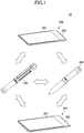
- FIG. 1 illustrates a communication system 10 according to the present embodiment.
- the communication system 10 includes a terminal device 100, a smartphone 200, a smartphone 300, and a stylus 400.
- the terminal device 100 and the stylus 400 can perform wireless communication with the smartphones 200 and 300 using Bluetooth Low Energy (BLE).
- BLE Bluetooth Low Energy
- the smartphone 200 is a first device which is a source device of an object to be acquired by the terminal device 100 or the stylus 400
- the smartphone 300 is a second device which is a destination device of an object to be output by the terminal device 100 or the stylus 400.
- the terminal device 100 and the stylus 400 can also output an object acquired from the smartphone 300 to the smartphone 200.
- a third device having the same functions as the terminal device 100 can be designated as a destination device to print an object, and the terminal device 100 or the stylus 400 can output the object to the third device to print the object.
- the terminal device 100 and the stylus 400 may be collectively referred to as a "terminal device 100a".
- the terminal device 100a can acquire an object selected on the touch panel 203.
- the terminal device 100a can also move or rotate an object displayed on the touch panel 203.
- the terminal device 100a can cause the smartphone 300 to display an object acquired from the smartphone 200 at a location on a touch panel 303 provided at a main unit 302 of the smartphone 300, which is selected by a touch operation to the touch panel 303.
- the terminal device 100 also has a printing function.
- the terminal device 100 may print an object acquired from the smartphone 200 on a recording sheet.
- the terminal device 100a can download data from the smartphones 200 and 300, and upload the data to the smartphones 300 and 200. By performing these operations, the terminal device 100a can share various types of data with the smartphones 200 and 300.
- FIG. 2A is a perspective view of the terminal device 100 and the smartphone 200 that are separated.
- FIG. 2B is a perspective view of the terminal device 100 and the smartphone 200 coupled with each other.
- a longitudinal direction of the smartphone 200 is referred to as an X-direction
- a short dimension direction of the smartphone 200 is referred to as a Y-direction
- a thickness direction of the smartphone 200 is referred to as a Z-direction.
- the terminal device 100 is detachable with respect to the smartphone 200, and can be carried with the smartphone 200 while the terminal device 100 is attached.
- the terminal device 100 is attached to the smartphone 200 with a binder 210.
- the smartphone 200 includes the main unit 202 and a jacket 204 attached to the main unit 202 so as to cover the main unit 202.
- the binder 210 can be attached to a back of the jacket 204 by a fixing means such as an adhesive agent.
- a cylindrical holder 212 is provided on a longer edge at -Y side of the binder 210.
- the holder 212 is openable.
- the terminal device 100 is set to the opened holder 212 as illustrated in FIG.
- an expansion cassette 150 (may also be referred to as a "cassette 150") and a built-in battery can be attached to the terminal device 100, while the terminal device 100 is attached to the smartphone 200. By attaching the cassette 150 to the terminal device 100, the terminal device 100 can perform a print operation.
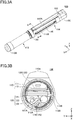
- FIG. 3A is an external perspective view of the terminal device 100.
- the pen-type terminal device 100 is a portable IoT (Internet of Things) device.
- the terminal device 100 includes the printing function and a wireless communication function.
- the terminal device 100 is approximately 18 mm to 20 mm in diameter, and approximately 165 mm to 170 mm in length.
- the terminal device 100 has the housing 110.
- a hook 110A is provided on the housing 110.
- the terminal device 100 can be held at a user's pocket provided at the user's chest by the hook 110A, similar to a pen.
- a cylindrical dial switch 130 is provided at an outer circumference of the housing 110.
- the dial switch 130 By operating the dial switch 130, a user can perform various operations of the terminal device 100, such as turning-on and turning-off operations of the terminal device 100, and an operation mode switching operation.
- the dial switch 130 can be pressed and rotated.
- An indicator 132 is provided on the hook 110A. By lighting of the indicator 132, various states of the terminal device 100 can be represented, such as a power supply state, a printing state, and the operation mode. For example, a light emitting diode (LED) is used as the indicator 132.
- a detachable cap 110B is provided at +X end of the housing 110 and a detachable cap 110C is provided at the other end of the housing 110.
- the terminal device 100 includes a power supply unit 113 and a printer unit 114.
- the printer unit 114 operates by using power supplied from the power supply unit 113 when the power supply unit 113 is connected.
- the printer unit 114 operates by power supplied from the cassette 150.
- the power supply unit 113 may be connected to the stylus 400 when the power supply unit 113 is disconnected from the printer unit 114.
- FIG. 3B is a cross-sectional view of the terminal device 100 taken along a line A-A in FIG. 3A .
- the housing 110 includes an outer cylinder 111 and an inner cylinder 112.
- the inner cylinder 112 is inserted to the outer cylinder 111, and the outer cylinder 111 is rotatable with respect to the inner cylinder 112.
- a sheet inlet 111A and a sheet outlet 111B are formed on the outer cylinder 111 and a sheet inlet 112A and a sheet outlet 112B are formed on the inner cylinder 112.
- a printing mechanism 120 is provided inside the inner cylinder 112 as illustrated in FIG. 3B .
- the printing mechanism 120 is an example of, and is referred to as a "print unit".
- the print unit 120 is a thermal printer that prints on a recording sheet supplied from the cassette 150.
- the print unit 120 includes a thermal head 121, a platen roller 122, a feed roller 123, a sheet guide 124, and a controller 125.
- the thermal head 121 includes multiple heating elements arranged side-by-side in the X-direction.
- the platen roller 122 is provided at a location facing the thermal head 121. As a recording sheet is sandwiched between the platen roller 122 and the thermal head 121, the recording sheet is pressed against the thermal head 121.
- the thermal head 121 heats the heating elements in accordance with control signals supplied from the controller 125 to form an image on a recording sheet.
- a recording sheet fed from the sheet inlet 111A and the sheet inlet 112A is fed to a gap between the thermal head 121 and the platen roller 122 along with the sheet guide 124 by rotating the feed roller 123.
- the controller 125 includes a head actuator and a motor actuator.
- the head actuator controls actuation of the thermal head 121 by supplying print data from a CPU (Central Processing Unit) 801 to the thermal head 121.
- the motor actuator controls actuation of a motor for sheet feeding based on motor control data from the CPU 801.
- FIG. 4 is an external perspective view of the terminal device 100 to which the cassette 150 is attached.
- a user rotates the outer cylinder 111 with respect to the inner cylinder 112 such that the sheet inlet 111A is aligned with the sheet inlet 112A and the sheet outlet 111B is aligned with the sheet outlet 112B, as illustrated in FIG. 3B .
- the user may attach the cassette 150 to the sheet inlet 111A.
- a recording sheet can be fed from the cassette 150 to the print unit 120 through the sheet inlet 111A and the sheet inlet 112A.
- the recording sheet is fed out of the print unit 120 through the sheet outlet 111B and the sheet outlet 112B.
- the cassette 150 can store multiple recording sheets inside.
- An example of a recording sheet is a label sheet of A8 size (52 mm ⁇ 74 mm).
- a user can immediately stick a label printed by the terminal device 100 on a notebook or the like.
- FIG. 5 illustrates the terminal device 100.
- the terminal device 100 can be divided into the power supply unit 113 and the printer unit 114.
- the power supply unit 113 can be connected to the stylus 400.
- the stylus 400 includes a dial switch 130B, the power supply unit 113, and the cap 110B.
- the printer unit 114 includes the hook 110A, the cap 110C, the print unit 120, and the dial switch 130A.
- the stylus 400 operates by power supplied from the power supply unit 113.
- An antenna 134A is provided at the stylus 400, and an antenna 134B is provided at the printer unit 114.
- the stylus 400 acquires an object from an external device through a touching operation on a touch panel of the external device using a tip 402 of the stylus 400, and transmits the acquired object to the printer unit 114 through wireless communication.
- the printer unit 114 operates by power supplied from the cassette 150.
- the printer unit 114 prints the object transmitted from the stylus 400.
- FIG. 6 is a block diagram illustrating the stylus 400 attached to the terminal device 100 and the cassette 150.
- FIG. 7 illustrates a block diagram of the separated stylus 400.
- both the stylus 400 and the terminal device 100 connected to the cassette 150 are used.
- the printer unit 114 and the stylus 400 can operate by using electric power supplied from the power supply units 113.
- the power supply unit 113 is only connected to the stylus 400.
- the stylus 400 operates by using electric power supplied from the power supply unit 113.
- the printer unit 114 operates by using electric power supplied from a power supply provided in the cassette 150 attached to the printer unit 114.
- the cassette 150 is attached to the printer unit 114.
- the printer unit 114 can operate by using electric power supplied from a power supply 151 in the cassette 150.
- the power supply unit 113 connected to the printer unit 114 and the power supply unit 113 connected to the stylus 400 in FIG. 6 are mutually independent modules, although both have the same functions.
- the stylus 400 is an example of a "first main unit", and the printer unit 114 is an example of a "second main unit”.
- a set of the terminal device 100 and the stylus 400 is an example of a "terminal device”. Both the stylus 400 and the terminal device 100 have similar functions except for a printing function.
- FIG. 8 is a block diagram illustrating a hardware configuration of the printer unit 114, the stylus 400, and the power supply unit 113.
- the stylus 400 includes the CPU 801, a memory 802, and a communication I/F (interface) 803, in addition to the antenna 134A and the dial switch 130B. Each of these components is interconnected via a bus 800.
- the CPU 801 executes programs stored in the memory 802, and controls operations of the stylus 400.
- the memory 802 stores the programs, and data necessary for the CPU 801 executing the programs. Examples of the memory 802 include a ROM (Read Only Memory) and a RAM (Random Access Memory).
- the communication I/F 803 controls wireless communication.
- a communication protocol used by the communication I/F 803 is BLE. However, a communication protocol is not limited to BLE, and Wi-Fi or NFC (Near Field Communication) may be used.
- the power supply unit 113 includes a power controller 804, a battery 805, a USB connector 806, and a charger 807.
- the power controller 804 is interposed between the battery 805 and the printer unit 114, or between the battery 805 and the stylus 400, and controls power supply to the printer unit 114 or the stylus 400 in accordance with an operation of the dial switch 130. By operating the dial switch 130A or 130B, the power controller 804 can switch the printer unit 114 or the stylus 400 between a power-on state and a power-off state.
- the battery 805 supplies direct-current electric power to the printer unit 114 or the stylus 400.
- a secondary cell such as a lithium ion battery, a lithium-ion polymer battery, and a nickel-hydrogen battery
- a primary cell such as a silver-oxide battery and a lithium battery may be used.
- the USB connector 806 is used for connecting a recharger. By detaching the cap 110B, the USB connector 806 is exposed.
- the charger 807 charges the battery 805 using electric power supplied from a recharger via the USB connector 806.
- the printer unit 114 includes a CPU 811, a memory 812, a communication I/F 813, and an expansion I/F 814, in addition to the print unit 120, the dial switch 130A, the indicator 132, and the antenna 134B. Each of these components is interconnected via a bus 810.
- the CPU 811 executes programs stored in the memory 812, and controls operations of the printer unit 114.
- the memory 812 stores the programs, and data necessary for the CPU 811 executing the programs.
- the memory 812 may be a ROM and a RAM.
- the communication I/F 813 controls wireless communication.
- the communication protocol used by the communication I/F 813 is BLE. However, Wi-Fi or NFC may be used for example.
- the expansion I/F 814 is electrically connected to an expansion cassette attached to the printer unit 114.
- Various types of expansion cassettes including the cassette 150 can be connected to the printer unit 114.
- the expansion I/F 814 When the cassette 150 functioning as an external power supply is attached to the expansion I/F 814, the expansion I/F 814 is electrically connected to the cassette 150, and electric power is supplied from the cassette 150 to the printer unit 114.
- the expansion I/F 814 When a cassette capable of selectively supplying a recording sheet among multiple types of recording sheets is connected, the expansion I/F 814 outputs a signal instructing a type of a recording sheet to the cassette.
- dial switches 130A and 130B can be operated in a similar manner. In the following, when the dial switches 130A and 130B are not distinguished, they are denoted as "dial switch 130".
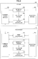
- FIG. 9 is a block diagram illustrating a functional configuration of the printer unit 114 and the stylus 400.
- the stylus 400 includes a communication module 901, a reception module 902, a retrieval module 903, a retention module 904, and an output controller 905.
- the communication module 901 controls communication with other devices such as the smartphone 200, the smartphone 300, and the printer unit 114.
- the communication module 901 controls connection, pairing, and data transmission/reception with other devices. Pairing is an operation for checking a header or a routing configuration by software in order to ensure connection security.
- the reception module 902 receives a signal output from the dial switch 130B in response to an operation of the dial switch 130B, such as a copy operation, a paste operation, a print operation or a rotate operation.
- the retrieval module 903 determines (settles) that the object is selected. If a copy operation signal is output from the dial switch 130B, the retrieval module 903 requests the smartphone 200 to upload the object, and acquires the uploaded object from the smartphone 200 in response to the request.
- the retention module 904 retains an object acquired by the retrieval module 903 in the memory 802.
- the output controller 905 outputs an object retained in the memory 802 in response to an operation of the dial switch 130B. If the dial switch 130B outputs a paste operation signal while a certain location on the touch panel 303 is being selected, the output controller 905 transmits an object in the memory 802 to the smartphone 300 to display the object at the selected location. If the dial switch 130B outputs a print operation signal while a printing function is being selected, the output controller 905 transmits a retained object to the printer unit 114 to print the object.
- the printer unit 114 includes a communication module 911, a print controller 912, a reception module 913, a retrieval module 914, a retention module 915, and an output controller 916.
- the communication module 911 controls communication with the stylus 400.
- the communication module 911 controls connection, pairing, and data transmission/reception with the stylus 400.
- the print controller 912 performs a print operation by the print unit 120 using print data received from the stylus 400.
- the reception module 913 receives various operation signals from the dial switch 130A being presses and/or rotated.
- the retrieval module 914, the retention module 915, and the output controller 916 are respectively similar to the retrieval module 903, the retention module 904, and the output controller 905 in the stylus 400.
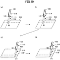
- FIG. 10 is a diagram illustrating copy and paste operations using the terminal device 100.
- the power supply unit 113 and the printer unit 114 are connected with each other.
- a pen-type cap 110F which is an example of a "touching part" is attached at a tip of the power supply unit 113. By using a tip of the cap 110F, a touching operation touching the touch panel 203 is performed.
- an object displayed at a location P1 on the touch panel 203 is selected by using the cap 110F.
- the terminal device 100 reports a selection of the object to the smartphone 200 via wireless communication by pressing the dial switch 130, and the selection of the object is determined (settled).
- a single press operation may correspond to a copy operation, and a double-press operation may correspond to a cut operation.
- settlement of selection may be achieved by a double-click operation on the touch panel 203, and by selecting a "select" button on a menu screen of the smartphone 200.
- a request for transmitting the object is sent from the terminal device 100 to the smartphone 200 by rotating the dial switch 130 clockwise.
- the object is transmitted from the smartphone 200 to the terminal device 100 via BLE communication.
- the dial switch 130 the object can be transmitted to the terminal device 100 by operating "copy" button on a menu screen of the smartphone 200.
- the terminal device 100 retains the received object in the memory 812.
- a paste position P2 on the touch panel 303 at which the object is to be pasted is selected by using the tip of the cap 110F.
- the paste position P2 is settled.
- the object retained in the memory 812 is transmitted to the smartphone 300, and the object is displayed on the paste position P2.
- the object can be displayed at the paste position P2 by selecting "paste" button on a menu screen of a display unit.
- the terminal device 100 can replicate an object on the touch panel 203 by pasting the object acquired from the location P1 on the touch panel 203 on a different location by the paste operation.
- the terminal device 100 can also copy an object to devices other than the smartphones 200 and 300.
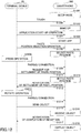
- FIG. 11 is a diagram illustrating a sequence of a copy process performed by the terminal device 100 and the smartphone 200.
- the smartphone 200 is in a standby state (S1101).
- the terminal device 100 performs a start-up operation of an application program (APP) of the smartphone 200 (S1102) while the smartphone 200 is in a standby state, the smartphone 200 starts the APP (S1103).
- the smartphone 200 selects the object (S1105).
- the dial switch 130 is pressed (S1106), the terminal device 100 performs a pairing and connection for communication with the smartphone 200 (S1107), and transmits a request for settling the object selection to the smartphone 200 (S1108).
- the smartphone 200 receives the request from the terminal device 100, the smartphone 200 settles the object selection (S1109), and transmits a notification of the settlement to the terminal device 100 (S1110).
- the terminal device 100 performs a pairing and connection for communication with the smartphone 200 (S1112), and transmits a request for sending the object (S1113).
- the smartphone 200 receives the request from the terminal device 100
- the smartphone 200 transmits the object to the terminal device 100 (S1114).
- the terminal device 100 receives the object from the smartphone 200 (S1115)
- the terminal device 100 sends a notification of completion of object retrieval (S1116), and retains the object in the memory 802 (S1117).
- FIG. 12 is a diagram illustrating a sequence of a paste process performed by the terminal device 100 and the smartphone 300.
- the smartphone 300 is in a sleep state (S1201).
- the smartphone 300 wakes up (S1203).
- the terminal device 100 performs a start-up operation of an APP of the smartphone 300 (S1204)
- the smartphone 300 starts the APP (S1205).
- the touch panel 303 is touched to select a paste position (S1206)
- the smartphone 300 selects the touched location as a paste position (S1207).
- the terminal device 100 performs a pairing and connection for communication with the smartphone 300 (S1209), and transmits a request for settlement of the paste position to the smartphone 300 (S1210).
- the smartphone 300 receives the request from the terminal device 100, the smartphone 300 settles the paste position (S1211), and transmits a notification of settlement of the paste position to the terminal device 100 (S1212).
- the terminal device 100 performs a pairing and connection for communication with the smartphone 300 (S1214), and transmits the object to the smartphone 300 (S1215).
- the smartphone 300 receives the object from the terminal device 100 (S1216), the smartphone 300 sends a notification of completion of object reception to the terminal device 100 (S1217), and displays the object to the paste position (S1218).
- FIGS. 10 to 12 illustrate operations and processes performed by the terminal device 100 in a state in which the power supply unit 113 and the printer unit 114 are connected with each other.
- the stylus 400 has similar functions with the printer unit 114, the stylus 400 connected to the power supply unit 113 can also perform the operations and the processes of FIGS. 10 to 12 .
- FIG. 13 is a diagram illustrating a print operation performed by the stylus 400.
- the power supply unit 113 and the stylus 400 are connected with each other.
- a touching operation is performed by using the tip 402 of the stylus 400.
- an object displayed at a location P1 on the touch panel 203 is selected by using the tip 402, after the APP of the smartphone 200 is started by touching the touch panel 203 as illustrated in a diagram (a) of FIG. 13 .
- the object selection is settled by pressing the dial switch 130B.
- a single press operation may correspond to a copy operation, and a double-press operation may correspond to a cut operation.
- the settlement may be achieved by double-click operation on the smartphone 200 or by selecting a "select" button on a menu screen of the smartphone 200.
- a request for transmitting an object is sent from the stylus 400 to the smartphone 200 by rotating the dial switch 130B clockwise.
- the smartphone 200 transmits the object to the stylus 400 via BLE communication.
- an object can be transmitted to the stylus 400 by selecting "copy" button on a menu screen of the smartphone 200.
- the stylus 400 retains the received object in the memory 802.
- the printer unit 114 is selected as a destination of print data, by a long press of the dial switch 130B and a rotation of the dial switch 130B after the long press, as illustrated in a diagram (c) of FIG. 13 . Further, the destination is settled by a double-press of the dial switch 130B, and a request for permission to transmit print data is issued to the printer unit 114.
- the indicator 132 starts blinking. When the dial switch 130A is pressed for a single time while the indicator 132 is blinking, transmission of print data is permitted. When the dial switch 130A is double-pressed while the indicator 132 is blinking, transmission of print data is rejected. With respect to an indicator of the stylus 400, red blinking represents that permission to transmit data is being requested, green lighting represents that data transmission has been permitted, and red lighting represents that data transmission has been rejected.
- the stylus 400 When transmission of the print data is permitted, the stylus 400 sends the print data in the memory 802 to the printer unit 114 in response to a counterclockwise rotation of the dial switch 130B as illustrated in a diagram (d) of FIG. 13 , and causes the printer unit 114 to print the object.
- the stylus 400 can transmit the object in the memory 802 to the destination.
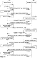
- FIG. 14 is a diagram illustrating a sequence of a print process performed by the stylus 400.
- An object retrieved from the smartphone 200 in a process similar to that illustrated in FIG. 11 is retained in the memory 802 in advance, before starting a process of FIG. 14 .
- the printer unit 114 is selected as a destination of print data by a long press operation of the dial switch 130B and a rotation of the dial switch 130B after the long press. Then, the destination is settled by a double-press operation of the dial switch 130B (S1401).
- the stylus 400 performs a pairing and connection for communication with the printer unit 114 (S1402), and issues a request for permission to transmit print data to the printer unit 114 (S1403).
- the printer unit 114 permits transmission of print data (S1404), and sends a notification of permission to transmit print data (S1405).
- the stylus 400 determines that the printer unit 114 is a data transmission destination (S1406) and the indicator of the stylus 400 is lit in green (S1407).
- the dial switch 130B is rotated counterclockwise (S1408), the stylus 400 transmits the print data to the printer unit 114 via BLE communication (S1409).
- the printer unit 114 prints the object by using the transmitted print data (S1410), and sends a notification indicating completion of the print operation to the stylus 400 (S1411).
- FIG. 15 is a diagram illustrating a rotation operation using the terminal device 100.
- the power supply unit 113 and the printer unit 114 are connected.
- the cap 110F is attached to the power supply unit 113.
- an object displayed at a location P1 on the touch panel 203 is selected. Further, by pressing the dial switch 130 for three times, selection of the object to be rotated is settled.
- the object can be rotated at the location P1. When a center of the object is selected as a rotational axis, the object is rotated around the center. When an edge of the object is selected as a rotational axis, the object is rotated around the edge.
- FIG. 16 is a diagram illustrating a sequence of an object rotation process performed by the terminal device 100 and the smartphone 200.
- the smartphone 200 is in a standby state (S1601).
- the smartphone 200 starts the APP (S1603).
- the smartphone 200 selects the object (S1605).
- the dial switch 130 is pressed for three times (S1606)
- the terminal device 100 performs a pairing and connection for communication with the smartphone 200 (S1607), and transmits a request for rotating the selected object to the smartphone 200 (S1608).
- the smartphone 200 receives the request from the terminal device 100, the smartphone 200 determines that the selected object is to be rotated (S1609).
- the terminal device 100 performs a pairing and connection for communication with the smartphone 200 (S1612) and transmits a request for settlement of the rotational axis to the smartphone 200 (S1613).
- the smartphone 200 receives the request from the terminal device 100, the smartphone 200 determines the rotational axis of the object (S1614).
- the terminal device 100 issues a request for rotating the object (S1616).
- the smartphone 200 receives the request, the smartphone 200 rotates the object (S1617).
- the terminal device 100 transmits to the smartphone 200 a request for settling the rotation of the object (S1619).
- the smartphone 200 receives the request, the smartphone 200 settles the rotate operation (S1620), and sends a notification of completion of object rotation to the terminal device 100 (S1621).
- FIGS. 15 and 16 illustrate processes of the terminal device 100 in which the power supply unit 113 and the printer unit 114 are connected. As the stylus 400 has similar functions with the printer unit 114, the stylus 400 can also perform the operations and the processes of FIGS. 15 and 16 .
- the terminal device 100a can enlarge or shrink a displayed object by the following procedures. First, the object displayed on the display unit is touched by the terminal device 100a. Next, selection of the object is settled by pressing the dial switch 130. Lastly, the object is enlarged or shrunk on the touch panel 203 by a rotation of the dial switch 130.
- the terminal device 100a can move an object on the display unit by the following procedures. First, the object displayed on the display unit is touched by the terminal device 100a. Next, the dial switch 130 is pressed while the object is touched by the terminal device 100a to select the object. Lastly, the selected object is moved on the display unit by dragging the terminal device 100a on the touch panel 203 while pressing the dial switch 130. A location of the object to be moved is settled when releasing the dial switch 130.
- the terminal device 100a can clip a part of an image displayed on the display unit along with a selection frame such as a triangle frame, a square frame, or a circular frame, by the following procedures. First, a clipping function for clipping along a square frame is selected from a submenu. Next, four vertexes of a square frame along which an image is clipped are designated on the touch panel 203 by touching the four vertexes and pressing the dial switch 130 while touching the vertexes. Lastly, an area of the image to be clipped is determined when the dial switch 130 is pressed twice after the four vertexes are selected.
- a selection frame such as a triangle frame, a square frame, or a circular frame
- the terminal device 100a may receive print data from the smartphones 200 and 300 or from other terminal devices 100 and print the print data by using a method other than the aforementioned copy operation. Further, the terminal device 100a can perform a print operation even if communication with other devices is not established, by using print data stored in the memory 802 or 812.
- the terminal device 100a can configure a group with one or more other devices such as smartphones, and can communicate with the other devices within the group using BLE communication (hereinafter, communication performed by devices within a group is referred to as "group communication").
- group communication communication performed by devices within a group.
- the terminal device 100a may function as a master device and the other device may function as slave devices.
- the other device may function as a master device, and the terminal device 100a may function as a slave device.
- the terminal device 100a can share various data with the other device by the group communication.
- the terminal device 100a can configure a group with one or more terminal devices 100B, and can perform group communication with the terminal devices 100B using BLE communication.
- the terminal device 100a may function as a master device, and the terminal devices 100B may function as slave devices.
- the terminal device 100a can share data with the terminal device 100B by group communication.
- the terminal device 100B has similar functions with the terminal device 100.
- the terminal device 100B can print, or can perform group communication similar to the terminal device 100.
- the terminal device 100B can also perform group communication with smartphones within a group, or can function as a master device.
- the terminal device 100a can configure a group with one or more sensor devices and perform group communication with the sensor devices using BLE communication.
- the terminal device 100a may function as a master device, and the sensor devices may function as slave devices. Types of the sensor devices are not limited to a specific type.
- Sensor devices may include a temperature sensor, an atmospheric pressure sensor, a position sensor, and an acceleration sensor.
- the terminal device 100a collects data detected by the sensor devices, such as temperature, atmospheric pressure, position, or acceleration, by group communication.
- the terminal device 100a can also store the data collected from the sensor devices ("detected data") into the memory 802 or 812, or can print out the detected data with the print unit 120. By printing out the detected data on a label sheet, the label sheet can be stuck on a notebook.
- the terminal device 100a can also output the detected data to the smartphone 200 or 300 or share the detected data with other devices by group communication.
- the amount of data transmitted through the group communication can be reduced by using context data having a predetermined data structure and common objects which are shared among multiple devices stored in a library of each device.
- objects and object identifiers associated with the respective objects are stored in the library.
- the library also stores multiple position information and position identifiers associated with the respective position information.
- the terminal device 100a and the other devices of the same group maintain their own libraries.
- the terminal device 100a receives context data contains an object identifier specifying an object to be printed and a position identifier specifying a position on which the object is to be printed from the smartphone 200. Based on the object identifier and the position identifier in the context data, the terminal device 100a identifies the object and the position to be printed.
- the terminal device 100a performs synchronization between its library and a library of the smartphone 200 in advance to retain the object to be printed in its library. Thus, the terminal device 100a can retrieve the object to be printed from its library and print out the object, without receiving the actual object from the smartphone 200.
- the terminal device 100a can synchronize its library with libraries of other devices of the same group.
- the terminal device 100a may transmit a local object stored in its own library to the other devices, and the other devices store the received object into respective libraries.
- the terminal device 100a may receive object stored in the libraries of the other devices and stores the object into its library. By performing these operations, the library of the terminal device 100a is synchronized with the libraries of the other devices.
- the terminal device 100a can collect multiple objects that are used by common application programs by receiving multiple pieces of context data from other devices within the same group. Also, the terminal device 100a can combine the multiple objects and transmit the multiple objects to the other devices in a form of context data. Accordingly, each device of the same group can share the same data, and can display or print the data.
- FIGS. 17A and 17B are diagrams illustrating examples of the terminal devices 100 to which the extension units are attached.
- a detachable extension unit 110D is provided at +X end of the housing 110.
- a detachable extension unit 110E is provided at the other end of the housing 110.
- the extension unit 110D is a nib unit.
- a writing instrument such as a ball-point pen is provided at the extension unit 110D, and a tip of the writing instrument projects from a tip of the extension unit 110D.
- the terminal device 100 may have a writing function in addition to a printing function and a communication function.
- a user can handwrite a comment on the printed label on a scrapbook or a notebook, and the terminal device 100 will be a functional and effective file management tool.
- the extension unit 110E is a laser pointer unit.
- a laser unit is provided inside the extension unit 110E, and a hole for emitting laser light is also provided.
- laser light from the extension unit 110E can be emitted to objects to be pointed such as a whiteboard.
- the terminal device 100 may have a laser pointer function in addition to a printing function and a communication function.
- the extension unit 110E is electrically connected to the terminal device 100 via a connection terminal, and the laser unit can be controlled by operating the dial switch 130.
- the stylus 400 is connected to the power supply unit 113 separated from the printer unit 114.
- the power supply unit 113 By connecting the power supply unit 113 to the stylus 400, a touching operation on a touch panel can be performed with the tip 402, and the stylus 400 can operate by electric power from the power supply unit 113.
- Various types of extension units can be attached to the power supply unit 113 instead of the cap 110B.
- the terminal device 100 can change a size of the label sheet in accordance with a size of the notebook.
- the size of the label sheet can be changed by changing types of the cassette 150, or by changing the size of the label sheet stored in the cassette 150.
- the terminal device 100 selects a size of a label sheet in accordance with the notebook.
- the terminal device 100a includes a switching unit for switching an operation mode of the terminal device 100a between a master mode and a slave mode.
- the terminal device 100a functions as a master device when the terminal device 100a is in the master mode, and functions as a slave device when the terminal device 100a is in the slave mode.
- the switching unit may switch the operation mode by an operation of the dial switch 130.
- the terminal device 100a may initially functions as a slave mode, and can be changed to a master mode when the dial switch 130 is operated. The operation mode is retained even if the terminal device 100a is turned off. If the terminal device 100a in a master mode is turned off, the terminal device 100a functions in a master mode when the terminal device 100a is turned on.
- the terminal device 100a in a slave mode If the terminal device 100a in a slave mode is turned off, the terminal device 100a functions in a slave mode when the terminal device 100a is turned on. When an operation for turning off power supply is made while the terminal device 100a is performing an operation for changing the operation mode, the terminal device 100a does not turn off immediately. The terminal device 100a maintains a power-on state until the operation mode change is completed. After the operation mode change is completed, the terminal device 100a notifies a user of the completion of the operation mode change with the indicator 132, and is then turned off.
- the terminal device 100a may include a collection unit, a generation unit, and a distribution unit as a function set of group communication.
- the collection unit collects data for an application program in a form of context data from slave terminal devices 100 or slave styluses 400 of the same group via group communication.
- the collection unit may collect data for a print application or for an SNS application from the slave device.
- the generation unit generates data for an application program, such as data for a print application or data for an SNS application, by using the data collected by the collection unit.
- the distribution unit distributes the data for the application program generated by the generation unit such as data for a print application and an SNS application to slave device.
- the terminal device 100a includes a management unit for group communication.
- the management unit manages information including a group ID and a list of users belonging to each group.
- the terminal device 100a selects one group for group communication among the groups managed by the management unit by an operation of the dial switch 130.
- the master terminal device 100a configures a group by connecting with other devices belonging to the selected group.
- the terminal device 100a can acquire an object from the smartphone 200 easily by operating the dial switch 130.
- the terminal device 100a can also manipulate the acquired object.
- the terminal device 100a can utilize the object in multiple purposes.
Landscapes
- Engineering & Computer Science (AREA)
- Theoretical Computer Science (AREA)
- General Engineering & Computer Science (AREA)
- Human Computer Interaction (AREA)
- General Physics & Mathematics (AREA)
- Physics & Mathematics (AREA)
- Signal Processing (AREA)
- Multimedia (AREA)
- Computer Networks & Wireless Communication (AREA)
- Computer Hardware Design (AREA)
- Computing Systems (AREA)
- Accessory Devices And Overall Control Thereof (AREA)
- Telephone Function (AREA)
- Printers Characterized By Their Purpose (AREA)
Abstract
Description
- The present disclosure relates to a terminal device and a communication system.
- A small-sized mobile printer in which a user can print at a place of visit and the like has been known (see
Patent Document 1, for example). - However, a complex operation needs to be performed on an external information processing apparatus in order to transmit print data to the mobile printer. Further, an object acquired from an external apparatus cannot be used for a purpose other than printing.
- [Patent Document 1] Japanese Laid-Open Patent Publication No.
2006-159427 - In order to solve the aforementioned problems, the present invention aims at providing a method of acquiring an object easily and utilizing the acquired object for various purposes.
- In order to solve the aforementioned problems, a terminal device according to one aspect of the present invention includes an operation part, a touching part, a communication module, and a retrieval module. The retrieval module is configured to retrieve an object displayed on a first apparatus from the first apparatus, in response to the operation part being operated while the object is selected by the touching part.
-
-
FIG. 1 is a diagram illustrating a communication system according to an embodiment; -
FIGS. 2A and 2B are diagrams illustrating perspective views of a terminal device and a smartphone; -
FIGS. 3A and 3B are diagrams illustrating an external perspective view and a cross-sectional view of the terminal device according to the embodiment; -
FIG. 4 is an external perspective view of the terminal device to which a cassette is attached; -
FIG. 5 is a diagram of a divided state of the terminal device according to the embodiment; -
FIG. 6 is a block diagram illustrating a stylus attached to the terminal device and the cassette; -
FIG. 7 is a block diagram illustrating a case in which the stylus is separated; -
FIG. 8 is a block diagram illustrating a hardware configuration of a printer unit, the stylus, and a power supply unit; -
FIG. 9 is a block diagram illustrating a the printer unit and the stylus; -
FIG. 10 is a diagram illustrating copy and paste operations using the terminal device; -
FIG. 11 is a diagram illustrating a sequence of a copy process performed by the terminal device and the smartphone; -
FIG. 12 is a diagram illustrating a sequence of a paste process; -
FIG. 13 is a diagram illustrating a print operation performed by using the stylus; -
FIG. 14 is a sequence diagram illustrating a sequence of procedures of a print process; -
FIG. 15 is a diagram illustrating an object rotate operation using the terminal device; -
FIG. 16 is a diagram illustrating a sequence of an object rotation process; and -
FIGS. 17A and 17B are diagrams illustrating the terminal devices to which the extension units are attached. - In the following, an embodiment of the present disclosure will be described.
-
FIG. 1 illustrates acommunication system 10 according to the present embodiment. Thecommunication system 10 includes aterminal device 100, asmartphone 200, asmartphone 300, and astylus 400. Theterminal device 100 and thestylus 400 can perform wireless communication with thesmartphones smartphone 200 is a first device which is a source device of an object to be acquired by theterminal device 100 or thestylus 400, and thesmartphone 300 is a second device which is a destination device of an object to be output by theterminal device 100 or thestylus 400. However, theterminal device 100 and thestylus 400 can also output an object acquired from thesmartphone 300 to thesmartphone 200. Further, a third device having the same functions as theterminal device 100 can be designated as a destination device to print an object, and theterminal device 100 or thestylus 400 can output the object to the third device to print the object. Theterminal device 100 and thestylus 400 may be collectively referred to as a "terminal device 100a". - By touching a
touch panel 203 provided at amain unit 202 of thesmartphone 200, the terminal device 100a can acquire an object selected on thetouch panel 203. The terminal device 100a can also move or rotate an object displayed on thetouch panel 203. Further, the terminal device 100a can cause thesmartphone 300 to display an object acquired from thesmartphone 200 at a location on atouch panel 303 provided at amain unit 302 of thesmartphone 300, which is selected by a touch operation to thetouch panel 303. - The
terminal device 100 also has a printing function. Theterminal device 100 may print an object acquired from thesmartphone 200 on a recording sheet. Further, the terminal device 100a can download data from thesmartphones smartphones smartphones -
FIG. 2A is a perspective view of theterminal device 100 and thesmartphone 200 that are separated.FIG. 2B is a perspective view of theterminal device 100 and thesmartphone 200 coupled with each other. In the following, a longitudinal direction of thesmartphone 200 is referred to as an X-direction, a short dimension direction of thesmartphone 200 is referred to as a Y-direction, and a thickness direction of thesmartphone 200 is referred to as a Z-direction. - As illustrated in
FIG. 2A and FIG. 2B , theterminal device 100 is detachable with respect to thesmartphone 200, and can be carried with thesmartphone 200 while theterminal device 100 is attached. As illustrated inFIG. 2A , theterminal device 100 is attached to thesmartphone 200 with abinder 210. Thesmartphone 200 includes themain unit 202 and ajacket 204 attached to themain unit 202 so as to cover themain unit 202. Thebinder 210 can be attached to a back of thejacket 204 by a fixing means such as an adhesive agent. On a longer edge at -Y side of thebinder 210, acylindrical holder 212 is provided. Theholder 212 is openable. Theterminal device 100 is set to the openedholder 212 as illustrated inFIG. 2A , and theholder 212 is closed as illustrated inFIG. 2B to securely hold theterminal device 100. An inner diameter of theholder 212 is substantially equal to an outer diameter of ahousing 110 of theterminal device 100. Accordingly, theholder 212 can hold theterminal device 100 without wobbling. Further, as illustrated inFIG. 2B , an expansion cassette 150 (may also be referred to as a "cassette 150") and a built-in battery can be attached to theterminal device 100, while theterminal device 100 is attached to thesmartphone 200. By attaching thecassette 150 to theterminal device 100, theterminal device 100 can perform a print operation. -
FIG. 3A is an external perspective view of theterminal device 100. The pen-type terminal device 100 is a portable IoT (Internet of Things) device. Theterminal device 100 includes the printing function and a wireless communication function. For example, theterminal device 100 is approximately 18 mm to 20 mm in diameter, and approximately 165 mm to 170 mm in length. As illustrated inFIG. 3A , theterminal device 100 has thehousing 110. Ahook 110A is provided on thehousing 110. Thus, theterminal device 100 can be held at a user's pocket provided at the user's chest by thehook 110A, similar to a pen. Acylindrical dial switch 130 is provided at an outer circumference of thehousing 110. By operating thedial switch 130, a user can perform various operations of theterminal device 100, such as turning-on and turning-off operations of theterminal device 100, and an operation mode switching operation. Thedial switch 130 can be pressed and rotated. Anindicator 132 is provided on thehook 110A. By lighting of theindicator 132, various states of theterminal device 100 can be represented, such as a power supply state, a printing state, and the operation mode. For example, a light emitting diode (LED) is used as theindicator 132. Adetachable cap 110B is provided at +X end of thehousing 110 and adetachable cap 110C is provided at the other end of thehousing 110. Theterminal device 100 includes apower supply unit 113 and aprinter unit 114. Theprinter unit 114 operates by using power supplied from thepower supply unit 113 when thepower supply unit 113 is connected. When thecassette 150 is connected to theprinter unit 114, theprinter unit 114 operates by power supplied from thecassette 150. Thepower supply unit 113 may be connected to thestylus 400 when thepower supply unit 113 is disconnected from theprinter unit 114. -
FIG. 3B is a cross-sectional view of theterminal device 100 taken along a line A-A inFIG. 3A . Thehousing 110 includes anouter cylinder 111 and aninner cylinder 112. Theinner cylinder 112 is inserted to theouter cylinder 111, and theouter cylinder 111 is rotatable with respect to theinner cylinder 112. Asheet inlet 111A and asheet outlet 111B are formed on theouter cylinder 111 and asheet inlet 112A and asheet outlet 112B are formed on theinner cylinder 112. - A
printing mechanism 120 is provided inside theinner cylinder 112 as illustrated inFIG. 3B . Theprinting mechanism 120 is an example of, and is referred to as a "print unit". Theprint unit 120 is a thermal printer that prints on a recording sheet supplied from thecassette 150. Theprint unit 120 includes athermal head 121, aplaten roller 122, a feed roller 123, asheet guide 124, and acontroller 125. - The
thermal head 121 includes multiple heating elements arranged side-by-side in the X-direction. Theplaten roller 122 is provided at a location facing thethermal head 121. As a recording sheet is sandwiched between theplaten roller 122 and thethermal head 121, the recording sheet is pressed against thethermal head 121. Thethermal head 121 heats the heating elements in accordance with control signals supplied from thecontroller 125 to form an image on a recording sheet. - A recording sheet fed from the
sheet inlet 111A and thesheet inlet 112A is fed to a gap between thethermal head 121 and theplaten roller 122 along with thesheet guide 124 by rotating the feed roller 123. - The
controller 125 includes a head actuator and a motor actuator. The head actuator controls actuation of thethermal head 121 by supplying print data from a CPU (Central Processing Unit) 801 to thethermal head 121. The motor actuator controls actuation of a motor for sheet feeding based on motor control data from theCPU 801. -
FIG. 4 is an external perspective view of theterminal device 100 to which thecassette 150 is attached. When performing a print operation using theterminal device 100, a user rotates theouter cylinder 111 with respect to theinner cylinder 112 such that thesheet inlet 111A is aligned with thesheet inlet 112A and thesheet outlet 111B is aligned with thesheet outlet 112B, as illustrated inFIG. 3B . Also, as illustrated inFIG. 4 , the user may attach thecassette 150 to thesheet inlet 111A. As a result, a recording sheet can be fed from thecassette 150 to theprint unit 120 through thesheet inlet 111A and thesheet inlet 112A. The recording sheet is fed out of theprint unit 120 through thesheet outlet 111B and thesheet outlet 112B. Thecassette 150 can store multiple recording sheets inside. An example of a recording sheet is a label sheet of A8 size (52 mm × 74 mm). Thus, a user can immediately stick a label printed by theterminal device 100 on a notebook or the like. -
FIG. 5 illustrates theterminal device 100. Theterminal device 100 can be divided into thepower supply unit 113 and theprinter unit 114. Thepower supply unit 113 can be connected to thestylus 400. Thestylus 400 includes adial switch 130B, thepower supply unit 113, and thecap 110B. Theprinter unit 114 includes thehook 110A, thecap 110C, theprint unit 120, and thedial switch 130A. Thestylus 400 operates by power supplied from thepower supply unit 113. Anantenna 134A is provided at thestylus 400, and anantenna 134B is provided at theprinter unit 114. Thestylus 400 acquires an object from an external device through a touching operation on a touch panel of the external device using atip 402 of thestylus 400, and transmits the acquired object to theprinter unit 114 through wireless communication. Theprinter unit 114 operates by power supplied from thecassette 150. Theprinter unit 114 prints the object transmitted from thestylus 400. -
FIG. 6 is a block diagram illustrating thestylus 400 attached to theterminal device 100 and thecassette 150.FIG. 7 illustrates a block diagram of the separatedstylus 400. - In
FIG. 6 , both thestylus 400 and theterminal device 100 connected to thecassette 150 are used. InFIG. 6 , as thepower supply units 113 are connected to theprinter unit 114 and thestylus 400 respectively, theprinter unit 114 and thestylus 400 can operate by using electric power supplied from thepower supply units 113. - In
FIG. 7 , thepower supply unit 113 is only connected to thestylus 400. Thus, only thestylus 400 operates by using electric power supplied from thepower supply unit 113. Theprinter unit 114 operates by using electric power supplied from a power supply provided in thecassette 150 attached to theprinter unit 114. - In both
FIG. 6 andFIG. 7 , thecassette 150 is attached to theprinter unit 114. Thus, theprinter unit 114 can operate by using electric power supplied from apower supply 151 in thecassette 150. Thepower supply unit 113 connected to theprinter unit 114 and thepower supply unit 113 connected to thestylus 400 inFIG. 6 are mutually independent modules, although both have the same functions. - In the present embodiment, the
stylus 400 is an example of a "first main unit", and theprinter unit 114 is an example of a "second main unit". A set of theterminal device 100 and thestylus 400 is an example of a "terminal device". Both thestylus 400 and theterminal device 100 have similar functions except for a printing function. -
FIG. 8 is a block diagram illustrating a hardware configuration of theprinter unit 114, thestylus 400, and thepower supply unit 113. Thestylus 400 includes theCPU 801, amemory 802, and a communication I/F (interface) 803, in addition to theantenna 134A and thedial switch 130B. Each of these components is interconnected via abus 800. - The
CPU 801 executes programs stored in thememory 802, and controls operations of thestylus 400. Thememory 802 stores the programs, and data necessary for theCPU 801 executing the programs. Examples of thememory 802 include a ROM (Read Only Memory) and a RAM (Random Access Memory). The communication I/F 803 controls wireless communication. In the present embodiment, a communication protocol used by the communication I/F 803 is BLE. However, a communication protocol is not limited to BLE, and Wi-Fi or NFC (Near Field Communication) may be used. - The
power supply unit 113 includes apower controller 804, abattery 805, aUSB connector 806, and acharger 807. Thepower controller 804 is interposed between thebattery 805 and theprinter unit 114, or between thebattery 805 and thestylus 400, and controls power supply to theprinter unit 114 or thestylus 400 in accordance with an operation of thedial switch 130. By operating thedial switch power controller 804 can switch theprinter unit 114 or thestylus 400 between a power-on state and a power-off state. Thebattery 805 supplies direct-current electric power to theprinter unit 114 or thestylus 400. In the present embodiment, a secondary cell, such as a lithium ion battery, a lithium-ion polymer battery, and a nickel-hydrogen battery, is used as thebattery 805. However, a primary cell such as a silver-oxide battery and a lithium battery may be used. TheUSB connector 806 is used for connecting a recharger. By detaching thecap 110B, theUSB connector 806 is exposed. Thecharger 807 charges thebattery 805 using electric power supplied from a recharger via theUSB connector 806. - The
printer unit 114 includes aCPU 811, amemory 812, a communication I/F 813, and an expansion I/F 814, in addition to theprint unit 120, thedial switch 130A, theindicator 132, and theantenna 134B. Each of these components is interconnected via abus 810. TheCPU 811 executes programs stored in thememory 812, and controls operations of theprinter unit 114. Thememory 812 stores the programs, and data necessary for theCPU 811 executing the programs. Thememory 812 may be a ROM and a RAM. The communication I/F 813 controls wireless communication. The communication protocol used by the communication I/F 813 is BLE. However, Wi-Fi or NFC may be used for example. - The expansion I/
F 814 is electrically connected to an expansion cassette attached to theprinter unit 114. Various types of expansion cassettes including thecassette 150 can be connected to theprinter unit 114. When thecassette 150 functioning as an external power supply is attached to the expansion I/F 814, the expansion I/F 814 is electrically connected to thecassette 150, and electric power is supplied from thecassette 150 to theprinter unit 114. When a cassette capable of selectively supplying a recording sheet among multiple types of recording sheets is connected, the expansion I/F 814 outputs a signal instructing a type of a recording sheet to the cassette. - The dial switches 130A and 130B can be operated in a similar manner. In the following, when the dial switches 130A and 130B are not distinguished, they are denoted as "
dial switch 130". -
FIG. 9 is a block diagram illustrating a functional configuration of theprinter unit 114 and thestylus 400. Thestylus 400 includes acommunication module 901, areception module 902, aretrieval module 903, aretention module 904, and anoutput controller 905. - The
communication module 901 controls communication with other devices such as thesmartphone 200, thesmartphone 300, and theprinter unit 114. Thecommunication module 901 controls connection, pairing, and data transmission/reception with other devices. Pairing is an operation for checking a header or a routing configuration by software in order to ensure connection security. - The
reception module 902 receives a signal output from thedial switch 130B in response to an operation of thedial switch 130B, such as a copy operation, a paste operation, a print operation or a rotate operation. - If the
dial switch 130B is pressed while an object displayed on thetouch panel 203 is being selected by thestylus 400, theretrieval module 903 determines (settles) that the object is selected. If a copy operation signal is output from thedial switch 130B, theretrieval module 903 requests thesmartphone 200 to upload the object, and acquires the uploaded object from thesmartphone 200 in response to the request. - The
retention module 904 retains an object acquired by theretrieval module 903 in thememory 802. - The
output controller 905 outputs an object retained in thememory 802 in response to an operation of thedial switch 130B. If thedial switch 130B outputs a paste operation signal while a certain location on thetouch panel 303 is being selected, theoutput controller 905 transmits an object in thememory 802 to thesmartphone 300 to display the object at the selected location. If thedial switch 130B outputs a print operation signal while a printing function is being selected, theoutput controller 905 transmits a retained object to theprinter unit 114 to print the object. - The
printer unit 114 includes acommunication module 911, aprint controller 912, areception module 913, aretrieval module 914, aretention module 915, and anoutput controller 916. Thecommunication module 911 controls communication with thestylus 400. Thecommunication module 911 controls connection, pairing, and data transmission/reception with thestylus 400. Theprint controller 912 performs a print operation by theprint unit 120 using print data received from thestylus 400. Thereception module 913 receives various operation signals from thedial switch 130A being presses and/or rotated. Theretrieval module 914, theretention module 915, and theoutput controller 916 are respectively similar to theretrieval module 903, theretention module 904, and theoutput controller 905 in thestylus 400. -
FIG. 10 is a diagram illustrating copy and paste operations using theterminal device 100. InFIG. 10 , thepower supply unit 113 and theprinter unit 114 are connected with each other. A pen-type cap 110F which is an example of a "touching part" is attached at a tip of thepower supply unit 113. By using a tip of thecap 110F, a touching operation touching thetouch panel 203 is performed. First, as illustrated in a diagram (a) ofFIG. 10 , an object displayed at a location P1 on thetouch panel 203 is selected by using thecap 110F. Theterminal device 100 reports a selection of the object to thesmartphone 200 via wireless communication by pressing thedial switch 130, and the selection of the object is determined (settled). A single press operation may correspond to a copy operation, and a double-press operation may correspond to a cut operation. Instead of pressing thedial switch 130, settlement of selection may be achieved by a double-click operation on thetouch panel 203, and by selecting a "select" button on a menu screen of thesmartphone 200. - Next, as illustrated in a diagram (b) of
FIG. 10 , a request for transmitting the object is sent from theterminal device 100 to thesmartphone 200 by rotating thedial switch 130 clockwise. In response to the request, the object is transmitted from thesmartphone 200 to theterminal device 100 via BLE communication. Instead of rotating thedial switch 130, the object can be transmitted to theterminal device 100 by operating "copy" button on a menu screen of thesmartphone 200. Theterminal device 100 retains the received object in thememory 812. - Next, as illustrated in a diagram (c) of
FIG. 10 , a paste position P2 on thetouch panel 303 at which the object is to be pasted is selected by using the tip of thecap 110F. By a double-press operation of thedial switch 130, the paste position P2 is settled. Subsequently, as illustrated in a diagram (d) ofFIG. 10 , by rotating thedial switch 130 counterclockwise, the object retained in thememory 812 is transmitted to thesmartphone 300, and the object is displayed on the paste position P2. Instead of operating thedial switch 130, the object can be displayed at the paste position P2 by selecting "paste" button on a menu screen of a display unit. - The
terminal device 100 can replicate an object on thetouch panel 203 by pasting the object acquired from the location P1 on thetouch panel 203 on a different location by the paste operation. Theterminal device 100 can also copy an object to devices other than thesmartphones -
FIG. 11 is a diagram illustrating a sequence of a copy process performed by theterminal device 100 and thesmartphone 200. - First, the
smartphone 200 is in a standby state (S1101). When theterminal device 100 performs a start-up operation of an application program (APP) of the smartphone 200 (S1102) while thesmartphone 200 is in a standby state, thesmartphone 200 starts the APP (S1103). Next, when an object displayed on a display unit is selected by touching the touch panel 203 (S1104), thesmartphone 200 selects the object (S1105). Further, when thedial switch 130 is pressed (S1106), theterminal device 100 performs a pairing and connection for communication with the smartphone 200 (S1107), and transmits a request for settling the object selection to the smartphone 200 (S1108). When thesmartphone 200 receives the request from theterminal device 100, thesmartphone 200 settles the object selection (S1109), and transmits a notification of the settlement to the terminal device 100 (S1110). - Next, when the
dial switch 130 is rotated (S1111), theterminal device 100 performs a pairing and connection for communication with the smartphone 200 (S1112), and transmits a request for sending the object (S1113). When thesmartphone 200 receives the request from theterminal device 100, thesmartphone 200 transmits the object to the terminal device 100 (S1114). When theterminal device 100 receives the object from the smartphone 200 (S1115), theterminal device 100 sends a notification of completion of object retrieval (S1116), and retains the object in the memory 802 (S1117). -
FIG. 12 is a diagram illustrating a sequence of a paste process performed by theterminal device 100 and thesmartphone 300. - First, the
smartphone 300 is in a sleep state (S1201). When thecap 110F is touched on thetouch panel 303 during the sleep state of the smartphone 300 (S1202), thesmartphone 300 wakes up (S1203). When theterminal device 100 performs a start-up operation of an APP of the smartphone 300 (S1204), thesmartphone 300 starts the APP (S1205). Next, when thetouch panel 303 is touched to select a paste position (S1206), thesmartphone 300 selects the touched location as a paste position (S1207). Further, when thedial switch 130 is pressed for settling the paste position (S1208), theterminal device 100 performs a pairing and connection for communication with the smartphone 300 (S1209), and transmits a request for settlement of the paste position to the smartphone 300 (S1210). When thesmartphone 300 receives the request from theterminal device 100, thesmartphone 300 settles the paste position (S1211), and transmits a notification of settlement of the paste position to the terminal device 100 (S1212). - Next, when the
dial switch 130 is rotated for requesting for transmitting the object (S1213), theterminal device 100 performs a pairing and connection for communication with the smartphone 300 (S1214), and transmits the object to the smartphone 300 (S1215). When thesmartphone 300 receives the object from the terminal device 100 (S1216), thesmartphone 300 sends a notification of completion of object reception to the terminal device 100 (S1217), and displays the object to the paste position (S1218). -
FIGS. 10 to 12 illustrate operations and processes performed by theterminal device 100 in a state in which thepower supply unit 113 and theprinter unit 114 are connected with each other. As thestylus 400 has similar functions with theprinter unit 114, thestylus 400 connected to thepower supply unit 113 can also perform the operations and the processes ofFIGS. 10 to 12 . -
FIG. 13 is a diagram illustrating a print operation performed by thestylus 400. InFIG. 13 , thepower supply unit 113 and thestylus 400 are connected with each other. A touching operation is performed by using thetip 402 of thestylus 400. - First, an object displayed at a location P1 on the
touch panel 203 is selected by using thetip 402, after the APP of thesmartphone 200 is started by touching thetouch panel 203 as illustrated in a diagram (a) ofFIG. 13 . Next, the object selection is settled by pressing thedial switch 130B. A single press operation may correspond to a copy operation, and a double-press operation may correspond to a cut operation. Alternatively, the settlement may be achieved by double-click operation on thesmartphone 200 or by selecting a "select" button on a menu screen of thesmartphone 200. - Next, as illustrated in a diagram (b) of
FIG. 13 , a request for transmitting an object is sent from thestylus 400 to thesmartphone 200 by rotating thedial switch 130B clockwise. In response to the request, thesmartphone 200 transmits the object to thestylus 400 via BLE communication. Alternatively, an object can be transmitted to thestylus 400 by selecting "copy" button on a menu screen of thesmartphone 200. Thestylus 400 retains the received object in thememory 802. - Next, the
printer unit 114 is selected as a destination of print data, by a long press of thedial switch 130B and a rotation of thedial switch 130B after the long press, as illustrated in a diagram (c) ofFIG. 13 . Further, the destination is settled by a double-press of thedial switch 130B, and a request for permission to transmit print data is issued to theprinter unit 114. In response to receiving the request, theindicator 132 starts blinking. When thedial switch 130A is pressed for a single time while theindicator 132 is blinking, transmission of print data is permitted. When thedial switch 130A is double-pressed while theindicator 132 is blinking, transmission of print data is rejected. With respect to an indicator of thestylus 400, red blinking represents that permission to transmit data is being requested, green lighting represents that data transmission has been permitted, and red lighting represents that data transmission has been rejected. - When transmission of the print data is permitted, the
stylus 400 sends the print data in thememory 802 to theprinter unit 114 in response to a counterclockwise rotation of thedial switch 130B as illustrated in a diagram (d) ofFIG. 13 , and causes theprinter unit 114 to print the object. - By selecting other smartphones or other terminal devices as a data transmission destination, the
stylus 400 can transmit the object in thememory 802 to the destination. -
FIG. 14 is a diagram illustrating a sequence of a print process performed by thestylus 400. An object retrieved from thesmartphone 200 in a process similar to that illustrated inFIG. 11 is retained in thememory 802 in advance, before starting a process ofFIG. 14 . First, theprinter unit 114 is selected as a destination of print data by a long press operation of thedial switch 130B and a rotation of thedial switch 130B after the long press. Then, the destination is settled by a double-press operation of thedial switch 130B (S1401). Thestylus 400 performs a pairing and connection for communication with the printer unit 114 (S1402), and issues a request for permission to transmit print data to the printer unit 114 (S1403). When thedial switch 130A is pressed for a single time, theprinter unit 114 permits transmission of print data (S1404), and sends a notification of permission to transmit print data (S1405). In response to the notification, thestylus 400 determines that theprinter unit 114 is a data transmission destination (S1406) and the indicator of thestylus 400 is lit in green (S1407). Subsequently, when thedial switch 130B is rotated counterclockwise (S1408), thestylus 400 transmits the print data to theprinter unit 114 via BLE communication (S1409). Theprinter unit 114 prints the object by using the transmitted print data (S1410), and sends a notification indicating completion of the print operation to the stylus 400 (S1411). -
FIG. 15 is a diagram illustrating a rotation operation using theterminal device 100. InFIG. 15 , thepower supply unit 113 and theprinter unit 114 are connected. Thecap 110F is attached to thepower supply unit 113. First, as illustrated in a diagram (a) ofFIG. 15 , an object displayed at a location P1 on thetouch panel 203 is selected. Further, by pressing thedial switch 130 for three times, selection of the object to be rotated is settled. Next, after a rotational axis of the object is selected by rotating thedial switch 130 as illustrated in a diagram (b) ofFIG. 15 , the object can be rotated at the location P1. When a center of the object is selected as a rotational axis, the object is rotated around the center. When an edge of the object is selected as a rotational axis, the object is rotated around the edge. -
FIG. 16 is a diagram illustrating a sequence of an object rotation process performed by theterminal device 100 and thesmartphone 200. First, thesmartphone 200 is in a standby state (S1601). When theterminal device 100 performs a start-up operation of an APP while thesmartphone 200 is in a standby state (S1602), thesmartphone 200 starts the APP (S1603). Next, when an object displayed on a display unit is selected by touching the object (S1604), thesmartphone 200 selects the object (S1605). Then, when thedial switch 130 is pressed for three times (S1606), theterminal device 100 performs a pairing and connection for communication with the smartphone 200 (S1607), and transmits a request for rotating the selected object to the smartphone 200 (S1608). When thesmartphone 200 receives the request from theterminal device 100, thesmartphone 200 determines that the selected object is to be rotated (S1609). - Next, when a rotational axis of the object is selected by the terminal device 100 (S1610) and the
dial switch 130 is pressed (S1611), theterminal device 100 performs a pairing and connection for communication with the smartphone 200 (S1612) and transmits a request for settlement of the rotational axis to the smartphone 200 (S1613). When thesmartphone 200 receives the request from theterminal device 100, thesmartphone 200 determines the rotational axis of the object (S1614). - Next, when the
dial switch 130 is rotated (S1615), theterminal device 100 issues a request for rotating the object (S1616). When thesmartphone 200 receives the request, thesmartphone 200 rotates the object (S1617). - When the
dial switch 130 is pressed (S1618), theterminal device 100 transmits to the smartphone 200 a request for settling the rotation of the object (S1619). When thesmartphone 200 receives the request, thesmartphone 200 settles the rotate operation (S1620), and sends a notification of completion of object rotation to the terminal device 100 (S1621). -
FIGS. 15 and16 illustrate processes of theterminal device 100 in which thepower supply unit 113 and theprinter unit 114 are connected. As thestylus 400 has similar functions with theprinter unit 114, thestylus 400 can also perform the operations and the processes ofFIGS. 15 and16 . - In the following, other functions of the terminal device 100a will be described.
- The terminal device 100a can enlarge or shrink a displayed object by the following procedures. First, the object displayed on the display unit is touched by the terminal device 100a. Next, selection of the object is settled by pressing the
dial switch 130. Lastly, the object is enlarged or shrunk on thetouch panel 203 by a rotation of thedial switch 130. - The terminal device 100a can move an object on the display unit by the following procedures. First, the object displayed on the display unit is touched by the terminal device 100a. Next, the
dial switch 130 is pressed while the object is touched by the terminal device 100a to select the object. Lastly, the selected object is moved on the display unit by dragging the terminal device 100a on thetouch panel 203 while pressing thedial switch 130. A location of the object to be moved is settled when releasing thedial switch 130. - The terminal device 100a can clip a part of an image displayed on the display unit along with a selection frame such as a triangle frame, a square frame, or a circular frame, by the following procedures. First, a clipping function for clipping along a square frame is selected from a submenu. Next, four vertexes of a square frame along which an image is clipped are designated on the
touch panel 203 by touching the four vertexes and pressing thedial switch 130 while touching the vertexes. Lastly, an area of the image to be clipped is determined when thedial switch 130 is pressed twice after the four vertexes are selected. - The terminal device 100a may receive print data from the
smartphones terminal devices 100 and print the print data by using a method other than the aforementioned copy operation. Further, the terminal device 100a can perform a print operation even if communication with other devices is not established, by using print data stored in thememory - The terminal device 100a can configure a group with one or more other devices such as smartphones, and can communicate with the other devices within the group using BLE communication (hereinafter, communication performed by devices within a group is referred to as "group communication"). The terminal device 100a may function as a master device and the other device may function as slave devices. Alternatively, the other device may function as a master device, and the terminal device 100a may function as a slave device. The terminal device 100a can share various data with the other device by the group communication.
- The terminal device 100a can configure a group with one or more terminal devices 100B, and can perform group communication with the terminal devices 100B using BLE communication. The terminal device 100a may function as a master device, and the terminal devices 100B may function as slave devices. The terminal device 100a can share data with the terminal device 100B by group communication. Note that the terminal device 100B has similar functions with the
terminal device 100. Thus, the terminal device 100B can print, or can perform group communication similar to theterminal device 100. The terminal device 100B can also perform group communication with smartphones within a group, or can function as a master device. - The terminal device 100a can configure a group with one or more sensor devices and perform group communication with the sensor devices using BLE communication. The terminal device 100a may function as a master device, and the sensor devices may function as slave devices. Types of the sensor devices are not limited to a specific type. Sensor devices may include a temperature sensor, an atmospheric pressure sensor, a position sensor, and an acceleration sensor. The terminal device 100a collects data detected by the sensor devices, such as temperature, atmospheric pressure, position, or acceleration, by group communication. The terminal device 100a can also store the data collected from the sensor devices ("detected data") into the
memory print unit 120. By printing out the detected data on a label sheet, the label sheet can be stuck on a notebook. The terminal device 100a can also output the detected data to thesmartphone - The amount of data transmitted through the group communication can be reduced by using context data having a predetermined data structure and common objects which are shared among multiple devices stored in a library of each device.
- For example, objects and object identifiers associated with the respective objects are stored in the library. The library also stores multiple position information and position identifiers associated with the respective position information. The terminal device 100a and the other devices of the same group maintain their own libraries. The terminal device 100a receives context data contains an object identifier specifying an object to be printed and a position identifier specifying a position on which the object is to be printed from the
smartphone 200. Based on the object identifier and the position identifier in the context data, the terminal device 100a identifies the object and the position to be printed. The terminal device 100a performs synchronization between its library and a library of thesmartphone 200 in advance to retain the object to be printed in its library. Thus, the terminal device 100a can retrieve the object to be printed from its library and print out the object, without receiving the actual object from thesmartphone 200. - The terminal device 100a can synchronize its library with libraries of other devices of the same group. The terminal device 100a may transmit a local object stored in its own library to the other devices, and the other devices store the received object into respective libraries. The terminal device 100a may receive object stored in the libraries of the other devices and stores the object into its library. By performing these operations, the library of the terminal device 100a is synchronized with the libraries of the other devices.
- The terminal device 100a can collect multiple objects that are used by common application programs by receiving multiple pieces of context data from other devices within the same group. Also, the terminal device 100a can combine the multiple objects and transmit the multiple objects to the other devices in a form of context data. Accordingly, each device of the same group can share the same data, and can display or print the data.
- Various types of extension units can be attached to the
terminal device 100.FIGS. 17A and 17B are diagrams illustrating examples of theterminal devices 100 to which the extension units are attached. InFIG. 17A , adetachable extension unit 110D is provided at +X end of thehousing 110. Also, at the other end of thehousing 110, adetachable extension unit 110E is provided. - The
extension unit 110D is a nib unit. A writing instrument such as a ball-point pen is provided at theextension unit 110D, and a tip of the writing instrument projects from a tip of theextension unit 110D. By attaching theextension unit 110D to theterminal device 100, a user can write on a printed recording sheet or on a notebook, with theextension unit 110D. By attaching theextension unit 110D, theterminal device 100 may have a writing function in addition to a printing function and a communication function. A user can handwrite a comment on the printed label on a scrapbook or a notebook, and theterminal device 100 will be a functional and effective file management tool. - The
extension unit 110E is a laser pointer unit. A laser unit is provided inside theextension unit 110E, and a hole for emitting laser light is also provided. By attaching theextension unit 110E to theterminal device 100, laser light from theextension unit 110E can be emitted to objects to be pointed such as a whiteboard. By attaching theextension unit 110E, theterminal device 100 may have a laser pointer function in addition to a printing function and a communication function. Theextension unit 110E is electrically connected to theterminal device 100 via a connection terminal, and the laser unit can be controlled by operating thedial switch 130. - In
FIG. 17B , thestylus 400 is connected to thepower supply unit 113 separated from theprinter unit 114. By connecting thepower supply unit 113 to thestylus 400, a touching operation on a touch panel can be performed with thetip 402, and thestylus 400 can operate by electric power from thepower supply unit 113. Various types of extension units can be attached to thepower supply unit 113 instead of thecap 110B. - When printing out an object on a label sheet, the
terminal device 100 can change a size of the label sheet in accordance with a size of the notebook. The size of the label sheet can be changed by changing types of thecassette 150, or by changing the size of the label sheet stored in thecassette 150. When multiple sizes of label sheets can be stored in thecassette 150, theterminal device 100 selects a size of a label sheet in accordance with the notebook. - The terminal device 100a includes a switching unit for switching an operation mode of the terminal device 100a between a master mode and a slave mode. The terminal device 100a functions as a master device when the terminal device 100a is in the master mode, and functions as a slave device when the terminal device 100a is in the slave mode. The switching unit may switch the operation mode by an operation of the
dial switch 130. The terminal device 100a may initially functions as a slave mode, and can be changed to a master mode when thedial switch 130 is operated. The operation mode is retained even if the terminal device 100a is turned off. If the terminal device 100a in a master mode is turned off, the terminal device 100a functions in a master mode when the terminal device 100a is turned on. If the terminal device 100a in a slave mode is turned off, the terminal device 100a functions in a slave mode when the terminal device 100a is turned on. When an operation for turning off power supply is made while the terminal device 100a is performing an operation for changing the operation mode, the terminal device 100a does not turn off immediately. The terminal device 100a maintains a power-on state until the operation mode change is completed. After the operation mode change is completed, the terminal device 100a notifies a user of the completion of the operation mode change with theindicator 132, and is then turned off. - The terminal device 100a may include a collection unit, a generation unit, and a distribution unit as a function set of group communication. When the terminal device 100a is in the master mode, the collection unit collects data for an application program in a form of context data from
slave terminal devices 100 orslave styluses 400 of the same group via group communication. The collection unit may collect data for a print application or for an SNS application from the slave device. The generation unit generates data for an application program, such as data for a print application or data for an SNS application, by using the data collected by the collection unit. The distribution unit distributes the data for the application program generated by the generation unit such as data for a print application and an SNS application to slave device. - The terminal device 100a includes a management unit for group communication. The management unit manages information including a group ID and a list of users belonging to each group. When the terminal device 100a is in the master mode, the terminal device 100a selects one group for group communication among the groups managed by the management unit by an operation of the
dial switch 130. The master terminal device 100a configures a group by connecting with other devices belonging to the selected group. - The terminal device 100a according to the present embodiment can acquire an object from the
smartphone 200 easily by operating thedial switch 130. The terminal device 100a can also manipulate the acquired object. Thus, the terminal device 100a can utilize the object in multiple purposes. - Although the preferred embodiments of the present invention have been described above, the present invention is not limited to these embodiments. Various modifications and enhancements may be made without departing from the scope of the present invention.
Claims (7)
- A terminal device comprising:an operation part;a touching part;a communication module; anda retrieval module configured to retrieve an object displayed on a first external apparatus, in response to an operation of the operation part made while the object is selected by the touching part.
- The terminal device according to claim 1, further comprising a printing unit configured to print the object retrieved by the retrieval module.
- The terminal device according to claim 2, further comprising a first main unit and a second main unit communicable with each other;
the second main unit including the operation part, the retrieval module, the communication module, and the printing unit; the first main unit including another operation part, another retrieval module, the touching part, and another communication module. - The terminal device according to claim 3, further comprising a power supply unit connectable to any one of the first main unit and the second main unit; wherein
the second main unit is operable by receiving electric power from an external power supply included in an expansion cassette for expanding a function of the printing unit, in a case in which the expansion cassette is attached to the second main unit instead of the power supply unit. - The terminal device according to any one of claims 1 to 4, further comprising an output control module configured to transmit the object retrieved by the retrieval module to a second external apparatus via the communication module, and to cause the second external apparatus to display the object at a selected position on a display of the second external apparatus.
- A communication system comprising:a first apparatus; anda terminal device includingan operation part,a touching part,a communication module, anda retrieval module configured to retrieve an object displayed on the first apparatus from the first apparatus, in response to an operation of the operation part made while the object is selected on the first apparatus.
- The communication system according to claim 6, further comprising a second apparatus; wherein
the terminal device includes an output control module configured to transmit the object retrieved by the retrieval module to the second apparatus, and
the second apparatus is configured to display the object received from the terminal device at a selected position on its display unit.
Applications Claiming Priority (1)
| Application Number | Priority Date | Filing Date | Title |
|---|---|---|---|
| JP2018078888A JP2019185635A (en) | 2018-04-17 | 2018-04-17 | Terminal device and communication system |
Publications (1)
| Publication Number | Publication Date |
|---|---|
| EP3557404A1 true EP3557404A1 (en) | 2019-10-23 |
Family
ID=66396983
Family Applications (1)
| Application Number | Title | Priority Date | Filing Date |
|---|---|---|---|
| EP19169069.2A Ceased EP3557404A1 (en) | 2018-04-17 | 2019-04-12 | Terminal device and communication system |
Country Status (5)
| Country | Link |
|---|---|
| US (1) | US10754589B2 (en) |
| EP (1) | EP3557404A1 (en) |
| JP (1) | JP2019185635A (en) |
| KR (1) | KR102161916B1 (en) |
| CN (1) | CN110392172A (en) |
Families Citing this family (3)
| Publication number | Priority date | Publication date | Assignee | Title |
|---|---|---|---|---|
| TWD221730S (en) * | 2022-01-28 | 2022-10-21 | 安瀚科技股份有限公司 | digital data storage device |
| JP7791024B2 (en) * | 2022-03-24 | 2025-12-23 | 富士フイルム株式会社 | Instruction device, image generation device, drawing system, communication method, and communication program |
| JP7583104B2 (en) * | 2022-07-04 | 2024-11-13 | ハイブ カンパニー リミテッド | A station on which a terminal that provides a seat library pairing service is placed, a seat library pairing method using short-distance wireless communication, and a seat library pairing system |
Citations (3)
| Publication number | Priority date | Publication date | Assignee | Title |
|---|---|---|---|---|
| JP2006159427A (en) | 2004-12-02 | 2006-06-22 | Kokusai Chart Co | Portable printer using print sheet while switching depending on use |
| US20090091597A1 (en) * | 1999-05-25 | 2009-04-09 | Silverbrook Research Pty Ltd | Printer having driven printhead sealing arrangement |
| EP2701057A2 (en) * | 2012-08-23 | 2014-02-26 | Samsung Electronics Co., Ltd. | Information transmission |
Family Cites Families (16)
| Publication number | Priority date | Publication date | Assignee | Title |
|---|---|---|---|---|
| US5699494A (en) * | 1995-02-24 | 1997-12-16 | Lexmark International, Inc. | Remote replication of printer operator panel |
| JP3205489B2 (en) * | 1995-07-24 | 2001-09-04 | シャープ株式会社 | Pen editing information processing system |
| JPH09169190A (en) * | 1995-12-20 | 1997-06-30 | Brother Ind Ltd | Electronic pen |
| AUPQ439299A0 (en) * | 1999-12-01 | 1999-12-23 | Silverbrook Research Pty Ltd | Interface system |
| JP2009199165A (en) * | 2008-02-19 | 2009-09-03 | Sharp Corp | Stylus pen |
| US9258402B2 (en) * | 2009-04-14 | 2016-02-09 | Qualcomm Incorporated | System and method for controlling mobile devices |
| CN105183194B (en) * | 2010-05-11 | 2019-04-19 | 上海科斗电子科技有限公司 | A kind of felt pen |
| CN102681798A (en) * | 2011-03-17 | 2012-09-19 | 东友科技股份有限公司 | Printing system and method for portable communication device |
| US20140091623A1 (en) * | 2012-09-28 | 2014-04-03 | Keith Shippy | Power share controller |
| JP6003629B2 (en) * | 2012-12-27 | 2016-10-05 | ブラザー工業株式会社 | Program and mobile device |
| JP2014165708A (en) * | 2013-02-26 | 2014-09-08 | Ricoh Co Ltd | Image forming device, control method for image forming device, and program |
| CN107004238A (en) * | 2014-09-29 | 2017-08-01 | 双帆科技集团股份有限公司 | System and method for managing electronic health care nursing information |
| US20170285813A1 (en) * | 2016-03-29 | 2017-10-05 | Microsoft Technology Licensing, Llc | Touch-Input Support for an External Touch-Capable Display Device |
| JP6843680B2 (en) * | 2016-05-31 | 2021-03-17 | シャープ株式会社 | Display system, input device, display device, display method and program |
| US10768804B2 (en) * | 2016-09-06 | 2020-09-08 | Microsoft Technology Licensing, Llc | Gesture language for a device with multiple touch surfaces |
| CN206086019U (en) * | 2016-10-26 | 2017-04-12 | 陕西理工学院 | Printer |
-
2018
- 2018-04-17 JP JP2018078888A patent/JP2019185635A/en active Pending
-
2019
- 2019-04-11 US US16/381,221 patent/US10754589B2/en not_active Expired - Fee Related
- 2019-04-12 EP EP19169069.2A patent/EP3557404A1/en not_active Ceased
- 2019-04-16 KR KR1020190044162A patent/KR102161916B1/en not_active Expired - Fee Related
- 2019-04-16 CN CN201910301492.0A patent/CN110392172A/en active Pending
Patent Citations (3)
| Publication number | Priority date | Publication date | Assignee | Title |
|---|---|---|---|---|
| US20090091597A1 (en) * | 1999-05-25 | 2009-04-09 | Silverbrook Research Pty Ltd | Printer having driven printhead sealing arrangement |
| JP2006159427A (en) | 2004-12-02 | 2006-06-22 | Kokusai Chart Co | Portable printer using print sheet while switching depending on use |
| EP2701057A2 (en) * | 2012-08-23 | 2014-02-26 | Samsung Electronics Co., Ltd. | Information transmission |
Also Published As
| Publication number | Publication date |
|---|---|
| JP2019185635A (en) | 2019-10-24 |
| KR102161916B1 (en) | 2020-10-05 |
| US20190317704A1 (en) | 2019-10-17 |
| CN110392172A (en) | 2019-10-29 |
| US10754589B2 (en) | 2020-08-25 |
| KR20190121255A (en) | 2019-10-25 |
Similar Documents
| Publication | Publication Date | Title |
|---|---|---|
| JP6557473B2 (en) | System, communication apparatus, communication method and program | |
| EP3557404A1 (en) | Terminal device and communication system | |
| JP5991733B2 (en) | Network system, information processing apparatus, and communication method | |
| EP3226108A1 (en) | Electronic pen and position detection system | |
| JP6244861B2 (en) | Information processing system, information processing apparatus, information processing method, and program | |
| JP6302300B2 (en) | Information processing apparatus and method | |
| JP6202902B2 (en) | System, information processing apparatus, control method thereof, and program | |
| KR20150027000A (en) | Wireless communication apparatus, wireless communication method, and storage medium | |
| KR102298610B1 (en) | Communication system and printing device | |
| JP2016038610A (en) | Information processing device and program | |
| JP2019061670A (en) | Display device, imaging device, imaging system, display device control method and program | |
| EP3435226B1 (en) | Communication system , method of setting configuration information, and electronic apparatus | |
| CN101615085A (en) | Support mouse system, the device and method of information interaction among multiple computers | |
| EP2428874A1 (en) | Electronic pen communication | |
| CN107277743B (en) | Communication system, communication device, and control method | |
| JP2013254244A (en) | Information terminal and control method of the same, and program | |
| KR102224156B1 (en) | Mobile terminal and method for controlling the same | |
| JP2020123237A (en) | Information processing device, control method for information processing device, and program | |
| CN116088695A (en) | System upgrading method and related device | |
| KR100951639B1 (en) | Portable microcomputer device and computing system using same | |
| JP2004341718A (en) | Program synchronization system, communication network device, communication terminal device, program synchronization method and program | |
| US10599876B2 (en) | Data communication method between a stylus and a tablet computer | |
| JP2011095882A (en) | Data processor, image forming device, control method and program | |
| CN103959889A (en) | Recording medium and control method thereof | |
| JP6956248B2 (en) | Electronic pen and position detection system |
Legal Events
| Date | Code | Title | Description |
|---|---|---|---|
| PUAI | Public reference made under article 153(3) epc to a published international application that has entered the european phase |
Free format text: ORIGINAL CODE: 0009012 |
|
| STAA | Information on the status of an ep patent application or granted ep patent |
Free format text: STATUS: THE APPLICATION HAS BEEN PUBLISHED |
|
| AK | Designated contracting states |
Kind code of ref document: A1 Designated state(s): AL AT BE BG CH CY CZ DE DK EE ES FI FR GB GR HR HU IE IS IT LI LT LU LV MC MK MT NL NO PL PT RO RS SE SI SK SM TR |
|
| AX | Request for extension of the european patent |
Extension state: BA ME |
|
| STAA | Information on the status of an ep patent application or granted ep patent |
Free format text: STATUS: REQUEST FOR EXAMINATION WAS MADE |
|
| 17P | Request for examination filed |
Effective date: 20200416 |
|
| RBV | Designated contracting states (corrected) |
Designated state(s): AL AT BE BG CH CY CZ DE DK EE ES FI FR GB GR HR HU IE IS IT LI LT LU LV MC MK MT NL NO PL PT RO RS SE SI SK SM TR |
|
| STAA | Information on the status of an ep patent application or granted ep patent |
Free format text: STATUS: EXAMINATION IS IN PROGRESS |
|
| 17Q | First examination report despatched |
Effective date: 20210503 |
|
| STAA | Information on the status of an ep patent application or granted ep patent |
Free format text: STATUS: THE APPLICATION HAS BEEN REFUSED |
|
| 18R | Application refused |
Effective date: 20221016 |