EP3557316A1 - Anzeigevorrichtung - Google Patents
Anzeigevorrichtung Download PDFInfo
- Publication number
- EP3557316A1 EP3557316A1 EP18000386.5A EP18000386A EP3557316A1 EP 3557316 A1 EP3557316 A1 EP 3557316A1 EP 18000386 A EP18000386 A EP 18000386A EP 3557316 A1 EP3557316 A1 EP 3557316A1
- Authority
- EP
- European Patent Office
- Prior art keywords
- display device
- passage
- translucent
- light
- outlet opening
- Prior art date
- Legal status (The legal status is an assumption and is not a legal conclusion. Google has not performed a legal analysis and makes no representation as to the accuracy of the status listed.)
- Granted
Links
Images

Classifications
-
- G—PHYSICS
- G02—OPTICS
- G02F—OPTICAL DEVICES OR ARRANGEMENTS FOR THE CONTROL OF LIGHT BY MODIFICATION OF THE OPTICAL PROPERTIES OF THE MEDIA OF THE ELEMENTS INVOLVED THEREIN; NON-LINEAR OPTICS; FREQUENCY-CHANGING OF LIGHT; OPTICAL LOGIC ELEMENTS; OPTICAL ANALOGUE/DIGITAL CONVERTERS
- G02F1/00—Devices or arrangements for the control of the intensity, colour, phase, polarisation or direction of light arriving from an independent light source, e.g. switching, gating or modulating; Non-linear optics
- G02F1/01—Devices or arrangements for the control of the intensity, colour, phase, polarisation or direction of light arriving from an independent light source, e.g. switching, gating or modulating; Non-linear optics for the control of the intensity, phase, polarisation or colour
- G02F1/13—Devices or arrangements for the control of the intensity, colour, phase, polarisation or direction of light arriving from an independent light source, e.g. switching, gating or modulating; Non-linear optics for the control of the intensity, phase, polarisation or colour based on liquid crystals, e.g. single liquid crystal display cells
- G02F1/133—Constructional arrangements; Operation of liquid crystal cells; Circuit arrangements
- G02F1/1333—Constructional arrangements; Manufacturing methods
- G02F1/1335—Structural association of cells with optical devices, e.g. polarisers or reflectors
- G02F1/1336—Illuminating devices
- G02F1/133615—Edge-illuminating devices, i.e. illuminating from the side
Definitions
- the present invention relates to a display device comprising a support plate, at least one mounted on the support plate light source and a display in the form of a simple light display or a special display element, and in particular such a display device for a control panel of an electronic home appliance.
- the display Depending on the application of the display device should / can not run parallel to the carrier plate, the display. In this case, measures must be taken to direct the light emitted by the light source as lossless as possible to the display.
- measures must be taken to direct the light emitted by the light source as lossless as possible to the display.
- the use of optical fibers is known, with which the light can be passed along arbitrary routes, depending on the embodiment.
- the display device comprises a support plate; at least one light source mounted on the support plate; and a housing with an opaque housing wall and a translucent passage, wherein the translucent passage extending from one of the support plate and the at least one light source facing inlet opening to a support plate facing away from the outlet opening on.
- the translucent passage has at least one portion with a change in direction between the inlet opening and the outlet opening, so that the outlet opening in an angle other than 0 degrees (ie not parallel) to the carrier plate, and has the housing wall in the region of this section with direction change a light-reflecting design.
- the display device of the invention allows alignment of the display not parallel to the carrier plate.
- the display device of the invention only requires a housing with a translucent passage, which has a light-reflecting configured section with change in direction, so that it is possible to dispense with further components such as, for example, more costly light guides.
- the angle between the outlet opening of the passage and thus the display can be selected arbitrarily greater than 0 degrees depending on the design of the housing. For example, in preferred embodiments, this angle is about 45 degrees, about 90 degrees, or about 135 degrees. For example, in one particular embodiment of the invention, the angle may be about 180 degrees so that the display is approximately parallel to the carrier plate, but the viewing direction of a user on the display is opposite to the direction of emission of the light source.
- the light-reflecting configuration of the housing wall is preferably formed by a coating of the housing wall or a special surface finish of the housing wall.
- an insert with reflective properties can be used in the passage of the housing.
- the housing wall is designed to be light-reflecting, at least in the region of the section of the passage with a change in direction, but can optionally also be designed to be light-reflecting in the remaining sections of the passage.
- the translucent passage of the housing has at least one portion with a change in direction.
- one or more sections may be provided with a change in direction. In the case of several sections with change of direction, these in their entirety achieve the desired angular difference between the outlet opening and the display to the carrier plate.
- the housing is preferably a plastic housing.
- the housing may preferably be mounted on the carrier plate.
- the carrier plate is preferably a printed circuit board.
- the at least one light source is preferably a light-emitting diode.
- the outlet opening of the translucent passage can be open, for example, so that the display is designed as a simple light display, or in the outlet opening of the translucent passage, a display element can be arranged, so that the display is designed as a backlit display.
- the display element may be, for example, a simple translucent cover, a simple cover with a translucent pattern, an LCD display, or the like.
- the light-reflecting configuration of the housing wall in the region of the section with change of direction is preferably designed to bring about a specular or a diffuse reflection of the light emitted by the at least one light source.
- the exit opening of the translucent passage has a cross-sectional area that is larger than a cross-sectional area of a narrowest section of the translucent passage.
- the translucent passage has a funnel shape which widens toward the outlet opening and which can achieve the most uniform possible illumination of the outlet opening and thus of the display.
- the section of the passage with change of direction may preferably run at least partially planar, run at least partially curved or extend partially planar and partially curved.
- the translucent passage may preferably be hollow or filled with a transparent mass (e.g., synthetic resin).
- a transparent mass e.g., synthetic resin
- the invention also provides a control panel for an electronic household appliance with such a display device of the invention.
- the display device of the invention is advantageously used in electronic household appliances such as hobs, stoves, dishwashers, laundry treatment appliances, refrigerators and / or freezers, extractor hoods and the like.
- Fig. 1 a first embodiment of a display device according to the invention is shown.
- the display device has a carrier plate 10 in the form of a printed circuit board, on which one or more light sources 12 are mounted.
- the light sources 12 are, for example, light-emitting diodes.
- the display device further comprises a plastic housing 14, wherein the housing walls 16 of this housing 14 are substantially opaque.
- the housing 14 may for example be attached to the support plate 10, or vice versa, for example by means of latching or clamping connections.
- the housing 14 has a hollow passage 18 which extends from an inlet opening 20 to an outlet opening.
- the inlet opening 20 of the passage 18 faces the carrier plate 10 and is positioned in the region of the at least one light source 12.
- the outlet opening 22 is facing away from the carrier plate 10 and aligned at an angle of approximately 90 degrees to the carrier plate 10.
- the passage 18 has a section with change of direction 24.
- this section is formed with a change in direction 24 by a correspondingly curved or angled course of the housing wall 16 of the housing 14.
- the housing wall 16 may be provided, for example, with a specular or diffusely reflecting coating.
- a display element 28 preferably also secured therein.
- This display element 28 is backlit by the light of the light source 12.
- the display element 28 is, for example, an LCD display, a simple cover with a translucent pattern, or a simple translucent cover.
- the outlet opening 22 of the passage 18 and the indicator element 28 arranged therein have a cross-sectional area which is larger than a cross-section of the narrowest portion of the passage 18, which is in the region of the direction-changing section 24 in this embodiment.
- the passage has a funnel shape, which is further in the direction of the outlet opening, so that a more uniform backlighting of the display element 28 can be achieved.
- the housing wall 16 is designed to reflect light only in the section with change in direction 24 of the passage.
- the remaining portions of the passage may be wholly or partially designed to be light-reflecting.
- the passage 18 is hollow through the housing 14 and thus translucent.
- the passage 18 may also be filled with a transparent mass, for example made of synthetic resin. Such a translucent mass increases the diffusion effect for a more uniform backlighting of the display element 28 and at the same time protects the carrier plate 10 and the light sources 12.
- outlet opening 22 of the passage 18 and the display element 28 are aligned therein at an angle of about 90 degrees to the support plate 10. In other embodiments of the invention, other angles greater than 0 degrees can be realized by a corresponding design of the housing 14.
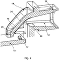
- Fig. 2 shows a second embodiment of a display device according to the invention. Therein, the same components are denoted by the same reference numerals as in the first embodiment.
- the display device of the second embodiment differs from that of the first embodiment in that the exit port 22 of the passage 18 is open, i. no display element 22 is provided in the outlet opening 22.
- the display is thus a simple light display, through which the light emitted by the light source 12 further emitted from the housing 14 out.
Landscapes
- Physics & Mathematics (AREA)
- Nonlinear Science (AREA)
- Mathematical Physics (AREA)
- Chemical & Material Sciences (AREA)
- Crystallography & Structural Chemistry (AREA)
- General Physics & Mathematics (AREA)
- Optics & Photonics (AREA)
- Illuminated Signs And Luminous Advertising (AREA)
Abstract
Description
- Die vorliegende Erfindung betrifft eine Anzeigevorrichtung mit einer Trägerplatte, wenigstens einer auf der Trägerplatte montierten Lichtquelle und einer Anzeige in Form einer einfachen Lichtanzeige oder eines speziellen Anzeigeelements, und insbesondere eine solche Anzeigevorrichtung für ein Bedienpanel eines elektronischen Haushaltsgeräts.
- Je nach Anwendungsfall der Anzeigevorrichtung soll / kann die Anzeige nicht parallel zur Trägerplatte verlaufen. In diesem Fall müssen Maßnahmen getroffen werden, um das von der Lichtquelle ausgesendete Licht möglichst verlustfrei zur Anzeige zu leiten. Zu diesem Zweck ist zum Beispiel der Einsatz von Lichtleitern bekannt, mit denen das Licht je nach Ausführungsform entlang beliebiger Strecken geleitet werden kann.
- Es ist die Aufgabe der Erfindung, eine verbesserte Anzeigevorrichtung mit einem einfachen und kostengünstigen Aufbau zu schaffen, bei der die Anzeige nicht parallel zur Trägerplatte verläuft.
- Diese Aufgabe wird gelöst durch eine Anzeigevorrichtung mit den Merkmalen des Anspruchs 1. Besonders vorteilhafte Ausgestaltungen und Weiterbildungen der Erfindung sind Gegenstand der abhängigen Ansprüche.
- Die erfindungsgemäße Anzeigevorrichtung weist eine Trägerplatte; wenigstens eine Lichtquelle, die auf der Trägerplatte montiert ist; und ein Gehäuse mit einer lichtundurchlässigen Gehäusewandung und einem lichtdurchlässigen Durchgang, wobei sich der lichtdurchlässige Durchgang von einer der Trägerplatte und der wenigstens einen Lichtquelle zugewandten Eintrittsöffnung zu einer der Trägerplatte abgewandten Austrittsöffnung erstreckt, auf. Außerdem weist der lichtdurchlässige Durchgang wenigstens einen Abschnitt mit Richtungsänderung zwischen der Eintrittsöffnung und der Austrittsöffnung auf, sodass die Austrittsöffnung in einem von 0 Grad verschiedenen Winkel (d.h. nicht parallel) zur Trägerplatte verläuft, und hat die Gehäusewandung im Bereich dieses Abschnitts mit Richtungsänderung eine lichtreflektierende Ausgestaltung.
- Die Anzeigevorrichtung der Erfindung ermöglicht eine Ausrichtung der Anzeige nicht parallel zur Trägerplatte. Hierzu benötigt die Anzeigevorrichtung der Erfindung lediglich ein Gehäuse mit einem lichtdurchlässigen Durchgang, der einen lichtreflektierend ausgestalteten Abschnitt mit Richtungsänderung aufweist, sodass auf weitere Bauteile wie beispielsweise kostenaufwändigere Lichtleiter verzichtet werden kann.
- Der Winkel zwischen der Austrittsöffnung des Durchgangs und damit der Anzeige kann je nach Ausgestaltung des Gehäuses beliebig größer 0 Grad gewählt werden. In bevorzugten Ausführungsformen beträgt dieser Winkel zum Beispiel etwa 45 Grad, etwa 90 Grad oder etwa 135 Grad. In einer speziellen Ausführungsform der Erfindung kann der Winkel zum Beispiel auch etwa 180 Grad betragen, sodass die Anzeige etwa parallel zur Trägerplatte ausgerichtet ist, die Betrachtungsrichtung eines Benutzers auf die Anzeige aber entgegengesetzt zur Aussenderichtung der Lichtquelle ist.
- Die lichtreflektierende Ausgestaltung der Gehäusewandung ist vorzugsweise durch eine Beschichtung der Gehäusewandung oder eine spezielle Oberflächenbeschaffenheit der Gehäusewandung ausgebildet. Alternativ kann in den Durchgang des Gehäuses auch ein Einsatz mit reflektierenden Eigenschaften eingesetzt werden. Die Gehäusewandung ist zumindest im Bereich des Abschnitts des Durchgangs mit Richtungsänderung lichtreflektierend ausgestaltet, kann aber wahlweise auch in den übrigen Abschnitten des Durchgangs lichtreflektierend ausgestaltet sein.
- Der lichtdurchlässige Durchgang des Gehäuses weist wenigstens einen Abschnitt mit Richtungsänderung auf. Je nach Ausführungsform können ein oder mehrere Abschnitte mit Richtungsänderung vorgesehen sein. Im Fall von mehreren Abschnitten mit Richtungsänderung erzielen diese in ihrer Gesamtheit die gewünschte Winkeldifferenz zwischen der Austrittsöffnung bzw. der Anzeige zur Trägerplatte.
- Das Gehäuse ist vorzugsweise ein Kunststoffgehäuse. Das Gehäuse kann vorzugsweise an der Trägerplatte montiert sein.
- Bei der Trägerplatte handelt es sich vorzugsweis um eine Leiterplatte. Bei der wenigstens einen Lichtquelle handelt es sich vorzugsweise um eine Leuchtdiode.
- Die Austrittsöffnung des lichtdurchlässigen Durchgangs kann zum Beispiel offen sein, sodass die Anzeige als einfache Lichtanzeige ausgestaltet ist, oder in der Austrittsöffnung des lichtdurchlässigen Durchgangs kann ein Anzeigeelement angeordnet sein, sodass die Anzeige als ein hinterleuchtetes Display ausgestaltet ist. Das Anzeigeelement kann zum Beispiel eine einfache lichtdurchlässige Abdeckung, eine einfache Abdeckung mit einem lichtdurchlässigen Muster, ein LCD-Display oder dergleichen sein.
- Die lichtreflektierende Ausgestaltung der Gehäusewandung im Bereich des Abschnitts mit Richtungsänderung ist bevorzugt ausgestaltet, um eine spiegelnde oder eine diffuse Reflexion des von der wenigstens einen Lichtquelle ausgesendeten Lichts zu bewirken.
- In einer Ausgestaltung der Erfindung hat die Austrittsöffnung des lichtdurchlässigen Durchgangs eine Querschnittsfläche, die größer ist als eine Querschnittsfläche eines engsten Abschnitts des lichtdurchlässigen Durchgangs. Hierdurch hat der lichtdurchlässige Durchgang eine sich zur Austrittsöffnung hin erweiternde Trichterform, die eine möglichst gleichmäßige Ausleuchtung der Austrittsöffnung und damit der Anzeige erreichen kann.
- Der Abschnitt des Durchgangs mit Richtungsänderung kann vorzugsweise zumindest teilweise plan verlaufen, zumindest teilweise gekrümmt verlaufen oder teilweise plan und teilweise gekrümmt verlaufen.
- Der lichtdurchlässige Durchgang kann vorzugswiese hohl sein oder mit einer lichtdurchlässigen Masse (z.B. Kunstharz) gefüllt sein.
- Gegenstand der Erfindung ist auch ein Bedienpanel für ein elektronisches Haushaltsgerät mit einer solchen Anzeigevorrichtung der Erfindung.
- Die Anzeigevorrichtung der Erfindung ist in vorteilhafter Weise bei elektronischen Haushaltsgeräten wie Kochfeldern, Herden, Spülmaschinen, Wäschebehandlungsgeräten, Kühl- und/oder Gefriergeräten, Dunstabzugshauben und dergleichen einsetzbar.
- Obige sowie weitere Merkmale und Vorteile der Erfindung werden aus der nachfolgenden Beschreibung bevorzugter, nicht-einschränkender Ausführungsbeispiele anhand der beiliegenden Zeichnung besser verständlich. Darin zeigen, zum Teil schematisch:
- Fig. 1
- eine perspektivische Teilschnittansicht einer Anzeigevorrichtung gemäß einem ersten Ausführungsbeispiel der Erfindung; und
- Fig. 2
- eine perspektivische Teilschnittansicht einer Anzeigevorrichtung gemäß einem zweiten Ausführungsbeispiel der Erfindung.
- In
Fig. 1 ist ein erstes Ausführungsbeispiel einer erfindungsgemäßen Anzeigevorrichtung dargestellt. - Die Anzeigevorrichtung weist eine Trägerplatte 10 in Form einer Leiterplatte auf, auf der ein oder mehrere Lichtquellen 12 montiert sind. Bei den Lichtquellen 12 handelt es sich zum Beispiel um Leuchtdioden.
- Die Anzeigevorrichtung weist ferner ein Kunststoff-Gehäuse 14 auf, wobei die Gehäusewandungen 16 dieses Gehäuses 14 im Wesentlichen lichtundurchlässig sind. Das Gehäuse 14 kann zum Beispiel an der Trägerplatte 10 befestigt sein, oder umgekehrt, beispielsweise mittels Rast- oder Klemmverbindungen.
- Das Gehäuse 14 weist einen hohlen Durchgang 18 auf, der sich von einer Eintrittsöffnung 20 zu einer Austrittsöffnung erstreckt. Die Eintrittsöffnung 20 des Durchgangs 18 ist der Trägerplatte 10 zugewandt und im Bereich der wenigstens einen Lichtquelle 12 positioniert. Die Austrittsöffnung 22 ist der Trägerplatte 10 abgewandt und in einem Winkel von etwa 90 Grad zur Trägerplatte 10 ausgerichtet.
- Damit das Licht von der wenigstens einen Lichtquelle 12 durch den Durchgang 18 des Gehäuses 14 bis zur Austrittsöffnung 22 gelangen kann, hat der Durchgang 18 einen Abschnitt mit Richtungsänderung 24. Wie in
Fig. 1 dargestellt, wird dieser Abschnitt mit Richtungsänderung 24 durch einen entsprechend gekrümmten bzw. gewinkelten Verlauf der Gehäusewandung 16 des Gehäuses 14 gebildet. Zudem ist die Gehäusewandung 16 im Bereich dieses Abschnitts mit Richtungsänderung 24 mit einer lichtreflektierend Ausgestaltung 26 versehen, wie inFig. 1 angedeutet. Hierzu kann die Gehäusewandung 16 zum Beispiel mit einer spiegelnden oder diffus reflektierenden Beschichtung versehen sein. - In dem Ausführungsbeispiel von
Fig. 1 ist ferner in der Austrittsöffnung 22 des Durchgangs 18 ein Anzeigeelement 28 angeordnet, vorzugsweise auch darin befestigt. Dieses Anzeigeelement 28 wird von dem Licht der Lichtquelle 12 hinterleuchtet. Bei dem Anzeigeelement 28 handelt es sich zum Beispiel um ein LCD-Display, eine einfache Abdeckung mit lichtdurchlässigem Muster oder eine einfache lichtdurchlässige Abdeckung. - Wie in
Fig. 1 dargestellt, haben die Austrittsöffnung 22 des Durchgangs 18 und das darin angeordnete Anzeigeelement 28 eine Querschnittsfläche, die größer ist als ein Querschnitt des engsten Abschnitts des Durchgangs 18, der in diesem Ausführungsbeispiel im Bereich des Abschnitts mit Richtungsänderung 24 ist. Hierdurch hat der Durchgang eine Trichterform, die in Richtung zur Austrittsöffnung hin weiter wird, sodass eine gleichmäßigere Hinterleuchtung des Anzeigeelements 28 erzielt werden kann. - In dem Ausführungsbeispiel von
Fig. 1 ist die Gehäusewandung 16 nur in dem Abschnitt mit Richtungsänderung 24 des Durchgangs lichtreflektierend ausgestaltet. In anderen Ausführungsformen der Erfindung können auch die übrigen Abschnitte des Durchgangs ganz oder teilweise lichtreflektierend ausgestaltet sein. - In dem Ausführungsbeispiel von
Fig. 1 ist der Durchgang 18 durch das Gehäuse 14 hohl und damit lichtdurchlässig. Alternativ kann der Durchgang 18 auch mit einer lichtdurchlässigen Masse zum Beispiel aus Kunstharz gefüllt sein. Eine solche lichtdurchlässige Masse erhöht die Diffusionswirkung für eine gleichmäßigere Hinterleuchtung des Anzeigeelements 28 und schützt zugleich die Trägerplatte 10 und die Lichtquellen 12. - In dem Ausführungsbeispiel von
Fig. 1 sind die Austrittsöffnung 22 des Durchgangs 18 und das Anzeigeelement 28 darin in einem Winkel von etwa 90 Grad zur Trägerplatte 10 ausgerichtet. In anderen Ausführungsformen der Erfindung können durch eine entsprechende Gestaltung des Gehäuses 14 auch andere Winkel größer als 0 Grad realisiert werden. -
Fig. 2 zeigt ein zweites Ausführungsbeispiel einer erfindungsgemäßen Anzeigevorrichtung. Darin sind die gleichen Komponenten mit den gleichen Bezugszeichen wie im ersten Ausführungsbeispiel gekennzeichnet. - Die Anzeigevorrichtung des zweiten Ausführungsbeispiels unterscheidet sich von jener des ersten Ausführungsbeispiels dadurch, dass die Austrittsöffnung 22 des Durchgangs 18 offen ist, d.h. kein Anzeigeelement 22 in der Austrittsöffnung 22 vorgesehen ist. Die Anzeige ist damit eine einfache Lichtanzeige, durch die das von der Lichtquelle 12 ausgesendete Licht weiter aus dem Gehäuse 14 heraus emittiert wird.
- Im Übrigen entsprechen Aufbau und Funktionsweise der Anzeigevorrichtung von
Fig. 2 jenen vonFig. 1 . Außerdem können auch die oben in Zusammenhang mitFig. 1 erläuterten Ausführungsvarianten bei der Anzeigevorrichtung vonFig. 2 angewendet werden. -
- 10
- Trägerplatte, insbes. Leiterplatte
- 12
- Lichtquelle, insbes. LED
- 14
- Gehäuse
- 16
- Gehäusewandung
- 18
- Durchgang
- 20
- Eintrittsöffnung
- 22
- Austrittsöffnung
- 24
- Abschnitt mit Richtungsänderung
- 26
- lichtreflektierende Ausgestaltung
- 28
- Anzeigeelement
Claims (7)
- Anzeigevorrichtung, aufweisend:eine Trägerplatte (10);wenigstens eine Lichtquelle (12), die auf der Trägerplatte (10) montiert ist; undein Gehäuse (14) mit einer lichtundurchlässigen Gehäusewandung (16) und einem lichtdurchlässigen Durchgang (18), wobei sich der lichtdurchlässige Durchgang (18) von einer der Trägerplatte (10) und der wenigstens einen Lichtquelle (12) zugewandten Eintrittsöffnung (20) zu einer der Trägerplatte (10) abgewandten Austrittsöffnung (22) erstreckt,wobei der lichtdurchlässige Durchgang (18) wenigstens einen Abschnitt mit Richtungsänderung (24) zwischen der Eintrittsöffnung (20) und der Austrittsöffnung (22) aufweist, sodass die Austrittsöffnung (22) in einem von 0 Grad verschiedenen Winkel zur Trägerplatte (10) verläuft, undwobei die Gehäusewandung (16) im Bereich des Abschnitts mit Richtungsänderung (24) eine lichtreflektierende Ausgestaltung (26) hat.
- Anzeigevorrichtung nach Anspruch 1, bei welcher
die Austrittsöffnung (22) des lichtdurchlässigen Durchgangs (18) offen ist oder in der Austrittsöffnung (22) des lichtdurchlässigen Durchgangs (18) ein Anzeigeelement (28) angeordnet ist. - Anzeigevorrichtung nach einem der vorhergehenden Ansprüche, bei welcher
die lichtreflektierende Ausgestaltung (26) der Gehäusewandung (16) im Bereich des Abschnitts mit Richtungsänderung (24) ausgestaltet ist, um eine spiegelnde oder eine diffuse Reflexion des von der wenigstens einen Lichtquelle (12) ausgesendeten Lichts zu bewirken. - Anzeigevorrichtung nach einem der vorhergehenden Ansprüche, bei welcher
die Austrittsöffnung (22) des lichtdurchlässigen Durchgangs (18) eine Querschnittsfläche hat, die größer ist als eine Querschnittsfläche eines engsten Abschnitts des lichtdurchlässigen Durchgangs (18). - Anzeigevorrichtung nach einem der vorhergehenden Ansprüche, bei welcher
der Abschnitt mit Richtungsänderung (24) zumindest teilweise plan verläuft und/oder zumindest teilweise gekrümmt verläuft. - Anzeigevorrichtung nach einem der vorhergehenden Ansprüche, bei welcher
der lichtdurchlässige Durchgang (18) hohl ist oder mit einer lichtdurchlässigen Masse gefüllt ist. - Bedienpanel für ein elektronisches Haushaltsgerät mit einer Anzeigevorrichtung nach einem der vorhergehenden Ansprüche.
Priority Applications (2)
| Application Number | Priority Date | Filing Date | Title |
|---|---|---|---|
| EP18000386.5A EP3557316B1 (de) | 2018-04-20 | 2018-04-20 | Anzeigevorrichtung |
| PL18000386.5T PL3557316T3 (pl) | 2018-04-20 | 2018-04-20 | Urządzenie wyświetlające |
Applications Claiming Priority (1)
| Application Number | Priority Date | Filing Date | Title |
|---|---|---|---|
| EP18000386.5A EP3557316B1 (de) | 2018-04-20 | 2018-04-20 | Anzeigevorrichtung |
Publications (2)
| Publication Number | Publication Date |
|---|---|
| EP3557316A1 true EP3557316A1 (de) | 2019-10-23 |
| EP3557316B1 EP3557316B1 (de) | 2022-12-21 |
Family
ID=62063243
Family Applications (1)
| Application Number | Title | Priority Date | Filing Date |
|---|---|---|---|
| EP18000386.5A Active EP3557316B1 (de) | 2018-04-20 | 2018-04-20 | Anzeigevorrichtung |
Country Status (2)
| Country | Link |
|---|---|
| EP (1) | EP3557316B1 (de) |
| PL (1) | PL3557316T3 (de) |
Citations (3)
| Publication number | Priority date | Publication date | Assignee | Title |
|---|---|---|---|---|
| DE10231255A1 (de) * | 2002-07-11 | 2004-01-29 | Diehl Ako Stiftung & Co. Kg | Hinterleuchtete Flüssigkristallanzeige, insbesondere zum Einsatz als Anzeigemodul hinter der Bedienblende eines Haushaltsgroßgerätes |
| WO2006128422A1 (de) * | 2005-05-31 | 2006-12-07 | Osram Opto Semiconductors Gmbh | Beleuchtungseinrichtung |
| EP2527892A1 (de) * | 2011-05-25 | 2012-11-28 | Samsung Electronics Co., Ltd. | Ebene Beleuchtungsvorrichtung und Flüssigkristallanzeige damit |
Family Cites Families (3)
| Publication number | Priority date | Publication date | Assignee | Title |
|---|---|---|---|---|
| JPH04136623A (ja) * | 1990-09-26 | 1992-05-11 | Sharp Corp | 電子レンジの液晶表示装置 |
| DE202007010458U1 (de) * | 2007-04-11 | 2007-10-04 | Fela Hilzinger Gmbh Leiterplattentechnik | Beleuchtungseinheit mit einer transparenten Trägerplatte und daraufsitzender Leuchtdiode |
| TWI515388B (zh) * | 2012-10-29 | 2016-01-01 | 緯創資通股份有限公司 | 具有暈光效果之發光裝置 |
-
2018
- 2018-04-20 EP EP18000386.5A patent/EP3557316B1/de active Active
- 2018-04-20 PL PL18000386.5T patent/PL3557316T3/pl unknown
Patent Citations (3)
| Publication number | Priority date | Publication date | Assignee | Title |
|---|---|---|---|---|
| DE10231255A1 (de) * | 2002-07-11 | 2004-01-29 | Diehl Ako Stiftung & Co. Kg | Hinterleuchtete Flüssigkristallanzeige, insbesondere zum Einsatz als Anzeigemodul hinter der Bedienblende eines Haushaltsgroßgerätes |
| WO2006128422A1 (de) * | 2005-05-31 | 2006-12-07 | Osram Opto Semiconductors Gmbh | Beleuchtungseinrichtung |
| EP2527892A1 (de) * | 2011-05-25 | 2012-11-28 | Samsung Electronics Co., Ltd. | Ebene Beleuchtungsvorrichtung und Flüssigkristallanzeige damit |
Also Published As
| Publication number | Publication date |
|---|---|
| EP3557316B1 (de) | 2022-12-21 |
| PL3557316T3 (pl) | 2023-04-17 |
Similar Documents
| Publication | Publication Date | Title |
|---|---|---|
| EP3392685B1 (de) | Rückblickvorrichtung für ein kraftfahrzeug | |
| EP2054257B1 (de) | Anzeigevorrichtung für ein kraftfahrzeug mit einem im wesentlichen parallelen lichtbündel | |
| DE3123369C2 (de) | ||
| EP2452434A1 (de) | Bedieneinrichtung für ein elektrogerät | |
| DE10102587A1 (de) | Beleuchtungseinrichtung mit Linienförmigen Lichtquellen | |
| DE102019201346B4 (de) | Dekorteil | |
| EP2986893B1 (de) | Leuchte | |
| EP1496380B1 (de) | Leuchtelement mit einer Leuchtdiode | |
| DE102017128841B4 (de) | Lichtleitkörper für eine Beleuchtungsvorrichtung eines Kraftfahrzeugs | |
| EP1106419B1 (de) | Bediengerät mit beleuchtbaren Bedienelementen | |
| EP2830220B1 (de) | Bedienteil für eine Bedieneinrichtung und Bedieneinrichtung | |
| DE102023127543A1 (de) | Beleuchtbares Verkleidungselement für Fahrzeuge | |
| DE102009025399A1 (de) | Leuchtkörper mit Reflektoren zur gleichmäßigen Flächenausleuchtung | |
| DE102014102355A1 (de) | Beleuchtungsvorrichtung für Fahrzeuge | |
| EP3557316B1 (de) | Anzeigevorrichtung | |
| EP3040231A2 (de) | Anzeigeinstrument zur anzeige eines betriebszustands eines kraftfahrzeugs | |
| DE10155126B4 (de) | Optischer Signalgeber, insbesondere in der Bedienblende eines Haushaltsgroßgerätes | |
| WO2020058236A1 (de) | Lichtmodul, insbesondere zur verwendung in einer beleuchtungsvorrichtung für ein kraftfahrzeug | |
| DE102010043715B4 (de) | Balkenanzeige | |
| EP2787282A1 (de) | Beleuchtungsvorrichtung für einen Innenraum eines Haushaltsgeräts sowie Haushaltsgerät mit einer derartigen Beleuchtungsvorrichtung | |
| DE10333316A1 (de) | Lichtleiterbauteil für optische Mehrsegmentsanzeigen | |
| EP2184728B1 (de) | Anzeigevorrichtung | |
| EP3602595B1 (de) | Moduldeckel für ein tastenmodul für eine taste, tastenmodul für eine taste und verfahren zum herstellen einer taste | |
| EP3212997A1 (de) | Optisches element sowie anordnung zur lichtabgabe mit einem optischen element | |
| DE19906129B4 (de) | Für eine Anzeigeeinrichtung bestimmter Lichtleiter |
Legal Events
| Date | Code | Title | Description |
|---|---|---|---|
| PUAI | Public reference made under article 153(3) epc to a published international application that has entered the european phase |
Free format text: ORIGINAL CODE: 0009012 |
|
| STAA | Information on the status of an ep patent application or granted ep patent |
Free format text: STATUS: THE APPLICATION HAS BEEN PUBLISHED |
|
| AK | Designated contracting states |
Kind code of ref document: A1 Designated state(s): AL AT BE BG CH CY CZ DE DK EE ES FI FR GB GR HR HU IE IS IT LI LT LU LV MC MK MT NL NO PL PT RO RS SE SI SK SM TR |
|
| AX | Request for extension of the european patent |
Extension state: BA ME |
|
| STAA | Information on the status of an ep patent application or granted ep patent |
Free format text: STATUS: REQUEST FOR EXAMINATION WAS MADE |
|
| 17P | Request for examination filed |
Effective date: 20200406 |
|
| RBV | Designated contracting states (corrected) |
Designated state(s): AL AT BE BG CH CY CZ DE DK EE ES FI FR GB GR HR HU IE IS IT LI LT LU LV MC MK MT NL NO PL PT RO RS SE SI SK SM TR |
|
| STAA | Information on the status of an ep patent application or granted ep patent |
Free format text: STATUS: EXAMINATION IS IN PROGRESS |
|
| 17Q | First examination report despatched |
Effective date: 20210318 |
|
| REG | Reference to a national code |
Ref country code: DE Ref legal event code: R079 Ref document number: 502018011251 Country of ref document: DE Free format text: PREVIOUS MAIN CLASS: G02F0001133500 Ipc: G02F0001133570 |
|
| GRAP | Despatch of communication of intention to grant a patent |
Free format text: ORIGINAL CODE: EPIDOSNIGR1 |
|
| STAA | Information on the status of an ep patent application or granted ep patent |
Free format text: STATUS: GRANT OF PATENT IS INTENDED |
|
| RIC1 | Information provided on ipc code assigned before grant |
Ipc: G02F 1/13357 20060101AFI20220722BHEP |
|
| INTG | Intention to grant announced |
Effective date: 20220826 |
|
| GRAS | Grant fee paid |
Free format text: ORIGINAL CODE: EPIDOSNIGR3 |
|
| GRAA | (expected) grant |
Free format text: ORIGINAL CODE: 0009210 |
|
| STAA | Information on the status of an ep patent application or granted ep patent |
Free format text: STATUS: THE PATENT HAS BEEN GRANTED |
|
| AK | Designated contracting states |
Kind code of ref document: B1 Designated state(s): AL AT BE BG CH CY CZ DE DK EE ES FI FR GB GR HR HU IE IS IT LI LT LU LV MC MK MT NL NO PL PT RO RS SE SI SK SM TR |
|
| REG | Reference to a national code |
Ref country code: GB Ref legal event code: FG4D Free format text: NOT ENGLISH |
|
| REG | Reference to a national code |
Ref country code: DE Ref legal event code: R096 Ref document number: 502018011251 Country of ref document: DE |
|
| REG | Reference to a national code |
Ref country code: CH Ref legal event code: EP |
|
| REG | Reference to a national code |
Ref country code: AT Ref legal event code: REF Ref document number: 1539408 Country of ref document: AT Kind code of ref document: T Effective date: 20230115 |
|
| REG | Reference to a national code |
Ref country code: IE Ref legal event code: FG4D Free format text: LANGUAGE OF EP DOCUMENT: GERMAN |
|
| REG | Reference to a national code |
Ref country code: LT Ref legal event code: MG9D |
|
| REG | Reference to a national code |
Ref country code: NL Ref legal event code: MP Effective date: 20221221 |
|
| PG25 | Lapsed in a contracting state [announced via postgrant information from national office to epo] |
Ref country code: SE Free format text: LAPSE BECAUSE OF FAILURE TO SUBMIT A TRANSLATION OF THE DESCRIPTION OR TO PAY THE FEE WITHIN THE PRESCRIBED TIME-LIMIT Effective date: 20221221 Ref country code: NO Free format text: LAPSE BECAUSE OF FAILURE TO SUBMIT A TRANSLATION OF THE DESCRIPTION OR TO PAY THE FEE WITHIN THE PRESCRIBED TIME-LIMIT Effective date: 20230321 Ref country code: LT Free format text: LAPSE BECAUSE OF FAILURE TO SUBMIT A TRANSLATION OF THE DESCRIPTION OR TO PAY THE FEE WITHIN THE PRESCRIBED TIME-LIMIT Effective date: 20221221 Ref country code: FI Free format text: LAPSE BECAUSE OF FAILURE TO SUBMIT A TRANSLATION OF THE DESCRIPTION OR TO PAY THE FEE WITHIN THE PRESCRIBED TIME-LIMIT Effective date: 20221221 |
|
| PG25 | Lapsed in a contracting state [announced via postgrant information from national office to epo] |
Ref country code: RS Free format text: LAPSE BECAUSE OF FAILURE TO SUBMIT A TRANSLATION OF THE DESCRIPTION OR TO PAY THE FEE WITHIN THE PRESCRIBED TIME-LIMIT Effective date: 20221221 Ref country code: LV Free format text: LAPSE BECAUSE OF FAILURE TO SUBMIT A TRANSLATION OF THE DESCRIPTION OR TO PAY THE FEE WITHIN THE PRESCRIBED TIME-LIMIT Effective date: 20221221 Ref country code: HR Free format text: LAPSE BECAUSE OF FAILURE TO SUBMIT A TRANSLATION OF THE DESCRIPTION OR TO PAY THE FEE WITHIN THE PRESCRIBED TIME-LIMIT Effective date: 20221221 Ref country code: GR Free format text: LAPSE BECAUSE OF FAILURE TO SUBMIT A TRANSLATION OF THE DESCRIPTION OR TO PAY THE FEE WITHIN THE PRESCRIBED TIME-LIMIT Effective date: 20230322 |
|
| PG25 | Lapsed in a contracting state [announced via postgrant information from national office to epo] |
Ref country code: NL Free format text: LAPSE BECAUSE OF FAILURE TO SUBMIT A TRANSLATION OF THE DESCRIPTION OR TO PAY THE FEE WITHIN THE PRESCRIBED TIME-LIMIT Effective date: 20221221 |
|
| PG25 | Lapsed in a contracting state [announced via postgrant information from national office to epo] |
Ref country code: SM Free format text: LAPSE BECAUSE OF FAILURE TO SUBMIT A TRANSLATION OF THE DESCRIPTION OR TO PAY THE FEE WITHIN THE PRESCRIBED TIME-LIMIT Effective date: 20221221 Ref country code: RO Free format text: LAPSE BECAUSE OF FAILURE TO SUBMIT A TRANSLATION OF THE DESCRIPTION OR TO PAY THE FEE WITHIN THE PRESCRIBED TIME-LIMIT Effective date: 20221221 Ref country code: PT Free format text: LAPSE BECAUSE OF FAILURE TO SUBMIT A TRANSLATION OF THE DESCRIPTION OR TO PAY THE FEE WITHIN THE PRESCRIBED TIME-LIMIT Effective date: 20230421 Ref country code: ES Free format text: LAPSE BECAUSE OF FAILURE TO SUBMIT A TRANSLATION OF THE DESCRIPTION OR TO PAY THE FEE WITHIN THE PRESCRIBED TIME-LIMIT Effective date: 20221221 Ref country code: EE Free format text: LAPSE BECAUSE OF FAILURE TO SUBMIT A TRANSLATION OF THE DESCRIPTION OR TO PAY THE FEE WITHIN THE PRESCRIBED TIME-LIMIT Effective date: 20221221 Ref country code: CZ Free format text: LAPSE BECAUSE OF FAILURE TO SUBMIT A TRANSLATION OF THE DESCRIPTION OR TO PAY THE FEE WITHIN THE PRESCRIBED TIME-LIMIT Effective date: 20221221 |
|
| PG25 | Lapsed in a contracting state [announced via postgrant information from national office to epo] |
Ref country code: SK Free format text: LAPSE BECAUSE OF FAILURE TO SUBMIT A TRANSLATION OF THE DESCRIPTION OR TO PAY THE FEE WITHIN THE PRESCRIBED TIME-LIMIT Effective date: 20221221 Ref country code: IS Free format text: LAPSE BECAUSE OF FAILURE TO SUBMIT A TRANSLATION OF THE DESCRIPTION OR TO PAY THE FEE WITHIN THE PRESCRIBED TIME-LIMIT Effective date: 20230421 Ref country code: AL Free format text: LAPSE BECAUSE OF FAILURE TO SUBMIT A TRANSLATION OF THE DESCRIPTION OR TO PAY THE FEE WITHIN THE PRESCRIBED TIME-LIMIT Effective date: 20221221 |
|
| REG | Reference to a national code |
Ref country code: DE Ref legal event code: R097 Ref document number: 502018011251 Country of ref document: DE |
|
| PLBE | No opposition filed within time limit |
Free format text: ORIGINAL CODE: 0009261 |
|
| STAA | Information on the status of an ep patent application or granted ep patent |
Free format text: STATUS: NO OPPOSITION FILED WITHIN TIME LIMIT |
|
| PG25 | Lapsed in a contracting state [announced via postgrant information from national office to epo] |
Ref country code: DK Free format text: LAPSE BECAUSE OF FAILURE TO SUBMIT A TRANSLATION OF THE DESCRIPTION OR TO PAY THE FEE WITHIN THE PRESCRIBED TIME-LIMIT Effective date: 20221221 |
|
| 26N | No opposition filed |
Effective date: 20230922 |
|
| REG | Reference to a national code |
Ref country code: CH Ref legal event code: PL |
|
| GBPC | Gb: european patent ceased through non-payment of renewal fee |
Effective date: 20230420 |
|
| PG25 | Lapsed in a contracting state [announced via postgrant information from national office to epo] |
Ref country code: LU Free format text: LAPSE BECAUSE OF NON-PAYMENT OF DUE FEES Effective date: 20230420 |
|
| REG | Reference to a national code |
Ref country code: BE Ref legal event code: MM Effective date: 20230430 |
|
| PG25 | Lapsed in a contracting state [announced via postgrant information from national office to epo] |
Ref country code: MC Free format text: LAPSE BECAUSE OF FAILURE TO SUBMIT A TRANSLATION OF THE DESCRIPTION OR TO PAY THE FEE WITHIN THE PRESCRIBED TIME-LIMIT Effective date: 20221221 |
|
| PG25 | Lapsed in a contracting state [announced via postgrant information from national office to epo] |
Ref country code: GB Free format text: LAPSE BECAUSE OF NON-PAYMENT OF DUE FEES Effective date: 20230420 |
|
| PG25 | Lapsed in a contracting state [announced via postgrant information from national office to epo] |
Ref country code: SI Free format text: LAPSE BECAUSE OF FAILURE TO SUBMIT A TRANSLATION OF THE DESCRIPTION OR TO PAY THE FEE WITHIN THE PRESCRIBED TIME-LIMIT Effective date: 20221221 Ref country code: MC Free format text: LAPSE BECAUSE OF FAILURE TO SUBMIT A TRANSLATION OF THE DESCRIPTION OR TO PAY THE FEE WITHIN THE PRESCRIBED TIME-LIMIT Effective date: 20221221 Ref country code: LI Free format text: LAPSE BECAUSE OF NON-PAYMENT OF DUE FEES Effective date: 20230430 Ref country code: GB Free format text: LAPSE BECAUSE OF NON-PAYMENT OF DUE FEES Effective date: 20230420 Ref country code: FR Free format text: LAPSE BECAUSE OF NON-PAYMENT OF DUE FEES Effective date: 20230430 Ref country code: CH Free format text: LAPSE BECAUSE OF NON-PAYMENT OF DUE FEES Effective date: 20230430 |
|
| REG | Reference to a national code |
Ref country code: IE Ref legal event code: MM4A |
|
| PG25 | Lapsed in a contracting state [announced via postgrant information from national office to epo] |
Ref country code: BE Free format text: LAPSE BECAUSE OF NON-PAYMENT OF DUE FEES Effective date: 20230430 |
|
| PG25 | Lapsed in a contracting state [announced via postgrant information from national office to epo] |
Ref country code: IE Free format text: LAPSE BECAUSE OF NON-PAYMENT OF DUE FEES Effective date: 20230420 |
|
| PG25 | Lapsed in a contracting state [announced via postgrant information from national office to epo] |
Ref country code: IE Free format text: LAPSE BECAUSE OF NON-PAYMENT OF DUE FEES Effective date: 20230420 |
|
| PG25 | Lapsed in a contracting state [announced via postgrant information from national office to epo] |
Ref country code: IT Free format text: LAPSE BECAUSE OF FAILURE TO SUBMIT A TRANSLATION OF THE DESCRIPTION OR TO PAY THE FEE WITHIN THE PRESCRIBED TIME-LIMIT Effective date: 20221221 |
|
| REG | Reference to a national code |
Ref country code: AT Ref legal event code: MM01 Ref document number: 1539408 Country of ref document: AT Kind code of ref document: T Effective date: 20230420 |
|
| PG25 | Lapsed in a contracting state [announced via postgrant information from national office to epo] |
Ref country code: AT Free format text: LAPSE BECAUSE OF NON-PAYMENT OF DUE FEES Effective date: 20230420 |
|
| PG25 | Lapsed in a contracting state [announced via postgrant information from national office to epo] |
Ref country code: AT Free format text: LAPSE BECAUSE OF NON-PAYMENT OF DUE FEES Effective date: 20230420 |
|
| PG25 | Lapsed in a contracting state [announced via postgrant information from national office to epo] |
Ref country code: BG Free format text: LAPSE BECAUSE OF FAILURE TO SUBMIT A TRANSLATION OF THE DESCRIPTION OR TO PAY THE FEE WITHIN THE PRESCRIBED TIME-LIMIT Effective date: 20221221 |
|
| PG25 | Lapsed in a contracting state [announced via postgrant information from national office to epo] |
Ref country code: BG Free format text: LAPSE BECAUSE OF FAILURE TO SUBMIT A TRANSLATION OF THE DESCRIPTION OR TO PAY THE FEE WITHIN THE PRESCRIBED TIME-LIMIT Effective date: 20221221 |
|
| PGFP | Annual fee paid to national office [announced via postgrant information from national office to epo] |
Ref country code: PL Payment date: 20250411 Year of fee payment: 8 Ref country code: DE Payment date: 20250612 Year of fee payment: 8 |
|
| PG25 | Lapsed in a contracting state [announced via postgrant information from national office to epo] |
Ref country code: CY Free format text: LAPSE BECAUSE OF FAILURE TO SUBMIT A TRANSLATION OF THE DESCRIPTION OR TO PAY THE FEE WITHIN THE PRESCRIBED TIME-LIMIT; INVALID AB INITIO Effective date: 20180420 |
|
| PG25 | Lapsed in a contracting state [announced via postgrant information from national office to epo] |
Ref country code: HU Free format text: LAPSE BECAUSE OF FAILURE TO SUBMIT A TRANSLATION OF THE DESCRIPTION OR TO PAY THE FEE WITHIN THE PRESCRIBED TIME-LIMIT; INVALID AB INITIO Effective date: 20180420 |
|
| PG25 | Lapsed in a contracting state [announced via postgrant information from national office to epo] |
Ref country code: TR Free format text: LAPSE BECAUSE OF FAILURE TO SUBMIT A TRANSLATION OF THE DESCRIPTION OR TO PAY THE FEE WITHIN THE PRESCRIBED TIME-LIMIT Effective date: 20221221 |