EP3557308A1 - Virtual reality head-mounted apparatus - Google Patents
Virtual reality head-mounted apparatus Download PDFInfo
- Publication number
- EP3557308A1 EP3557308A1 EP18758081.6A EP18758081A EP3557308A1 EP 3557308 A1 EP3557308 A1 EP 3557308A1 EP 18758081 A EP18758081 A EP 18758081A EP 3557308 A1 EP3557308 A1 EP 3557308A1
- Authority
- EP
- European Patent Office
- Prior art keywords
- partial
- lens
- camera
- reflection
- transmission
- Prior art date
- Legal status (The legal status is an assumption and is not a legal conclusion. Google has not performed a legal analysis and makes no representation as to the accuracy of the status listed.)
- Granted
Links
Images


Classifications
-
- G—PHYSICS
- G02—OPTICS
- G02B—OPTICAL ELEMENTS, SYSTEMS OR APPARATUS
- G02B27/00—Optical systems or apparatus not provided for by any of the groups G02B1/00 - G02B26/00, G02B30/00
- G02B27/01—Head-up displays
- G02B27/017—Head mounted
- G02B27/0172—Head mounted characterised by optical features
-
- G—PHYSICS
- G06—COMPUTING OR CALCULATING; COUNTING
- G06F—ELECTRIC DIGITAL DATA PROCESSING
- G06F3/00—Input arrangements for transferring data to be processed into a form capable of being handled by the computer; Output arrangements for transferring data from processing unit to output unit, e.g. interface arrangements
- G06F3/01—Input arrangements or combined input and output arrangements for interaction between user and computer
- G06F3/011—Arrangements for interaction with the human body, e.g. for user immersion in virtual reality
- G06F3/013—Eye tracking input arrangements
-
- G—PHYSICS
- G02—OPTICS
- G02B—OPTICAL ELEMENTS, SYSTEMS OR APPARATUS
- G02B27/00—Optical systems or apparatus not provided for by any of the groups G02B1/00 - G02B26/00, G02B30/00
- G02B27/01—Head-up displays
- G02B27/0101—Head-up displays characterised by optical features
- G02B2027/0138—Head-up displays characterised by optical features comprising image capture systems, e.g. camera
-
- G—PHYSICS
- G02—OPTICS
- G02B—OPTICAL ELEMENTS, SYSTEMS OR APPARATUS
- G02B27/00—Optical systems or apparatus not provided for by any of the groups G02B1/00 - G02B26/00, G02B30/00
- G02B27/01—Head-up displays
- G02B27/0101—Head-up displays characterised by optical features
- G02B2027/014—Head-up displays characterised by optical features comprising information/image processing systems
-
- G—PHYSICS
- G02—OPTICS
- G02B—OPTICAL ELEMENTS, SYSTEMS OR APPARATUS
- G02B27/00—Optical systems or apparatus not provided for by any of the groups G02B1/00 - G02B26/00, G02B30/00
- G02B27/01—Head-up displays
- G02B27/017—Head mounted
- G02B2027/0178—Eyeglass type
-
- G—PHYSICS
- G02—OPTICS
- G02B—OPTICAL ELEMENTS, SYSTEMS OR APPARATUS
- G02B27/00—Optical systems or apparatus not provided for by any of the groups G02B1/00 - G02B26/00, G02B30/00
- G02B27/0093—Optical systems or apparatus not provided for by any of the groups G02B1/00 - G02B26/00, G02B30/00 with means for monitoring data relating to the user, e.g. head-tracking, eye-tracking
-
- G—PHYSICS
- G02—OPTICS
- G02B—OPTICAL ELEMENTS, SYSTEMS OR APPARATUS
- G02B27/00—Optical systems or apparatus not provided for by any of the groups G02B1/00 - G02B26/00, G02B30/00
- G02B27/09—Beam shaping, e.g. changing the cross-sectional area, not otherwise provided for
- G02B27/0938—Using specific optical elements
- G02B27/095—Refractive optical elements
- G02B27/0955—Lenses
-
- G—PHYSICS
- G02—OPTICS
- G02B—OPTICAL ELEMENTS, SYSTEMS OR APPARATUS
- G02B27/00—Optical systems or apparatus not provided for by any of the groups G02B1/00 - G02B26/00, G02B30/00
- G02B27/10—Beam splitting or combining systems
- G02B27/14—Beam splitting or combining systems operating by reflection only
- G02B27/141—Beam splitting or combining systems operating by reflection only using dichroic mirrors
Definitions
- This application relates to the technical field of virtual reality, and in particular, to a virtual reality head-mounted apparatus.
- VR technology is a technology that comprehensively utilizes a computer graphics system and various control interfaces to generate an interactive three-dimensional interaction environment on a computer to provide users with immersive experience.
- a user can wear a VR head-mounted apparatus, such as VR glasses, a VR helmet, or another VR apparatus, to obtain corresponding VR experience.
- this application provides a VR head-mounted apparatus, which can improve the acquisition accuracy of an infrared image of an eye of a user.
- a VR head-mounted apparatus including:
- the partial-reflection partial-transmission lens has a high transmittance for visible light and a low transmittance for infrared light.
- the partial-reflection partial-transmission lens includes an infrared dichroic mirror.
- the camera is located outside a visible area of the convex lens with respect to the user.
- the partial-reflection partial-transmission lens has a plate shape, the lens surface of the partial-reflection partial-transmission lens is inclined upward, the camera is located at a top of the main body, and a lens of the camera is disposed obliquely downward.
- the partial-reflection partial-transmission lens has a plate shape, the lens surface of the partial-reflection partial-transmission lens is inclined downward, the camera is located at a bottom of the main body, and a lens of the camera is disposed obliquely upward.
- the partial-reflection partial-transmission lens includes an upper lens structure and a lower lens structure disposed obliquely, and a joint of the upper lens structure and the lower lens structure faces the user;
- the main body is provided with a first camera and a second camera, the first camera is located at a top of the main body and a lens of the first camera is disposed obliquely downward corresponding to the upper lens structure, and the second camera is located at a bottom of the main body and a lens of the second camera is disposed obliquely upward corresponding to the lower lens structure.
- the upper lens structure and the lower lens structure are symmetrical with respect to a horizontal plane.
- the apparatus further includes: a protective frame, the protective frame forming an accommodating space adapted to the partial-reflection partial-transmission lens and the convex lens, so as to accommodate and fix the partial-reflection partial-transmission lens and the convex lens.
- the apparatus further includes: an adjustment component, the adjustment component performing angle adjustment on the camera, such that the lens of the camera is kept toward a virtual image of the infrared image of the eye formed in the partial-reflection partial-transmission lens.
- a partial-reflection partial-transmission lens is provided in a VR head-mounted apparatus, and a lens surface of the partial-reflection partial-transmission lens is disposed obliquely.
- a deviation angle of a camera during the acquisition of the infrared image of the eye can be reduced, thus reducing the deformation and distortion of the infrared image of the eye, and helping to improve the acquisition accuracy for the infrared image of the eye.
- FIG. 1 is a side cross-sectional view of a VR helmet provided by an exemplary embodiment of this application.
- the VR helmet may include: a main body 1, the main body 1 being provided with a convex lens 2 and a VR playing component 5. Further, the main body 1 is further provided with a partial-reflection partial-transmission lens 3 for reflecting infrared light.
- the partial-reflection partial-transmission lens 3 is located on a side of the convex lens 2 closer to a user (i.e., the partial-reflection partial-transmission lens 3 is located between the convex lens 2 and an eye 6 of the user).
- VR display content played by the VR playing component 5 may, in a form of visible light S1, go through the partial-reflection partial-transmission lens 3 almost unaffected, and the eye 6 of the user receives the visible light S 1 to view of the VR display content, while infrared light S2 emitted from the eye 6 of the user is mostly or almost completely reflected by the partial-reflection partial-transmission lens 3.
- Corresponding reflected infrared light S2' is acquired by a camera 4 provided in the main body 1, and an infrared image of the eye 6 may be formed from the reflected infrared light S2' to achieve functions such as eye tracking and iris recognition.
- a lens surface 30 of the partial-reflection partial-transmission lens 3 is disposed obliquely, and positions of the partial-reflection partial-transmission lens 3 and the camera 4 correspond to each other, such that the lens surface 30 of the partial-reflection partial-transmission lens 3 can obliquely reflect the infrared light S2 corresponding to the infrared image of the eye 6 toward the camera 4.
- the camera 4 may be located at a lower edge of the main body 1 close to a user side (i.e., left side in FIG.
- a visible area formed between the eye 6 and the convex lens 2 may have a trapezoidal shape as shown in FIG. 1 (the cross section is trapezoidal; in fact, since the convex lens 2 is round, a 3-D shape corresponding to the visible area is approximately a cone), and a top surface and a bottom surface of the main body 1 are planar.
- the camera 4 is located inside an edge of the bottom surface of the main body 1, it is obvious that an installation space for the camera 4 is smaller as the camera moves closer to the convex lens 2 and the installation space for the camera 4 is larger as the camera moves closer to the eye 6.
- a larger installation space compared to a situation where the installation position of the camera 4 is close to the convex lens 2 can be obtained to adjust an installation angle of the camera 4 (e.g., to make it more parallel with the reflected infrared light S2') and reduce the foregoing angle ⁇ , thereby improving the acquisition accuracy of the camera 4 for the infrared image of the eye 6.
- the technical solutions of this application may be applied to any type of VR head-mounted apparatus.
- the VR helmet may be an integrated-style VR head-mounted apparatus, that is, the VR helmet may independently implement a VR playing function without resorting to an external apparatus.
- the VR playing component 5 is pre-built in the VR helmet to implement playing functions such as rendering and displaying of VR display content.
- the VR helmet may be a split-style VR head-mounted apparatus.
- the VR playing component 5 may include a mobile apparatus installed in the VR helmet, and the mobile apparatus may implement rendering through a processor, a graphics card chip, etc., and may perform content display through a screen component.
- the VR playing component 5 may be a display component built in the VR helmet, and the foregoing external apparatus is used to render VR display content and the like.
- the partial-reflection partial-transmission lens 3 for reflecting infrared light refers to a lens having a low transmittance for an infrared spectrum and a high transmittance for other spectra such as visible light.
- the partial-reflection partial-transmission lens 3 By blocking the low-transmittance infrared spectrum as much as possible, the partial-reflection partial-transmission lens 3 reflects the infrared spectrum, i.e., "partial-reflection.” Meanwhile, other spectra such as high-transmittance visible light can be transmitted through the partial-reflection partial-transmission lens 3 as much as possible, so that the partial-reflection partial-transmission lens 3's blocking or impact on other spectra such as the visible light can be minimized, i.e., "partial-transmission".
- the foregoing partial-reflection partial-transmission lens 3 for reflecting infrared light may be an infrared dichroic mirror, such that a visible spectrum may be almost completely transmitted and an infrared spectrum may be almost completely reflected.
- an infrared reflective film such as a TiO2-Ag-TiO2 infrared reflective film or a ZnS-Ag-ZnS infrared reflective film may be coated on a surface of an optical lens that has a high transmittance for visible light (the visible spectrum may be almost completely transmitted) to form the infrared dichroic mirror.
- a lens may be made based entirely on materials in the foregoing infrared reflective film or a similar preparation material to form the infrared dichroic mirror.
- a partial-reflection partial-transmission lens 3 is provided in a VR head-mounted apparatus, and a lens surface 30 of the partial-reflection partial-transmission lens 3 is disposed obliquely.
- a deviation angle of a camera 4 during the acquisition of the infrared image of the eye can be reduced, thus reducing the deformation and distortion of the infrared image of the eye, and helping to improve the acquisition accuracy for the infrared image of the eye.
- the lens 3 as a whole may be arranged obliquely, as shown in FIG. 1 .
- the lens surface 30 may be inclined in other manners.
- FIG. 2 when the partial-reflection partial-transmission lens 3 has a wedge-shaped cross section, a bottom surface of the partial-reflection partial-transmission lens 3 is in a vertical direction, and the lens surface 30 is inclined, thereby helping to reduce the installation difficulty of the partial-reflection partial-transmission lens 3 as the installation angle of the partial-reflection partial-transmission lens 3 does not need to be repeatedly adjusted.
- the lens surface 30 of the partial-reflection partial-transmission lens 3 is inclined downward, the camera 4 is located at a bottom of the main body 1, and the lens of the camera 4 is disposed obliquely upward, the infrared image of the eye 6 of the user can be acquired more completely, clearly and accurately under the same conditions.
- the embodiment as shown in FIG. 1 or FIG. 2 i.e., the lens surface 30 of the partial-reflection partial-transmission lens 3 is inclined downward, the camera 4 is located at a bottom of the main body 1, and the lens of the camera 4 is disposed obliquely upward, the infrared image of the eye 6 of the user can be acquired more completely, clearly and accurately under the same conditions.
- the lens surface 30 of the partial-reflection partial-transmission lens 3 is inclined upward, the camera 4 is located at a top of the main body 1, and the lens of the camera 4 is disposed obliquely downward, the infrared image of the eye 6 can also be obtained.
- FIG. 4 is a side cross-sectional view of a VR helmet provided by an exemplary embodiment of this application.
- the partial-reflection partial-transmission lens 3 may have other structures.
- the partial-reflection partial-transmission lens 3 in FIG. 4 may include an upper lens structure 3A and a lower lens structure 3B disposed obliquely, and a joint of the upper lens structure 3A and the lower lens structure 3B faces the user (i.e., in the embodiment shown in FIG. 4 , the upper lens structure 3A has its lower part inclined leftward and its upper part inclined rightward, and the lower lens structure 3B has its upper part inclined leftwards and its lower part inclined rightwards).
- the main body 1 is provided with a first camera 4A and a second camera 4B.
- the first camera 4A is located at the top of the main body 1 and a lens of the first camera 4A is disposed obliquely downward corresponding to the upper lens structure 3A
- the second camera 4B is located at the bottom of the main body 1 and a lens of the second camera 4B is disposed obliquely upward corresponding to the lower lens structure 3B.
- a positional relationship between the eye 6 and the partial-reflection partial-transmission lens 3 may be different for different users wearing a same VR apparatus.
- the eye 6 may not be exactly located in a middle position of the main body 1 as shown in FIGS. 1-3 , which may result in the camera 4 not being able to completely acquire the infrared image of the eye of the user.
- this application through the embodiments such as those shown in FIG. 4 , can ensure that infrared images of the eyes of a user can be completely acquired by the first camera 4A and the second camera 4B, regardless the positional changes, such as an upward shift or a downward shift, that may occur to the eyes of the user.
- an upper region of the infrared image of the eye 6 corresponds to a first infrared ray S21
- a lower region corresponds to a first infrared ray S22.
- the first infrared ray S21 can be reflected by an upper lens surface 30A of the upper lens structure 3A to form a first reflected infrared ray S21', which may be acquired by the first camera 4A.
- the second infrared ray S22 can be reflected by a lower lens surface 30B of the lower lens structure 3B to form a second reflected infrared ray S22', which may be acquired by the second camera 4B.
- the first reflected infrared ray S21' and the second reflected infrared ray S22' can be combined to obtain the infrared image of the eye 6.
- the first infrared ray S21 and the first infrared ray S22 may both be emitted toward the upper lens structure 3A and reflected by the upper lens surface 30A of the upper lens structure 3A to form the first reflected infrared ray S21' and the second reflected infrared ray S22'.
- the first camera 4A may acquire the first reflected infrared ray S21' and the second reflected infrared ray S22', and combined them to form the infrared image of the eye 6.
- the first infrared ray S21 and the first infrared ray S22 may both be emitted toward the lower lens structure 3B and reflected by the lower lens surface 30B of the lower lens structure 3B to obtain the first reflected infrared ray S21' and the second reflected infrared ray S22',
- the second camera 4B may acquire the first reflected infrared ray S21' and the second reflected infrared ray S22', and combine them to form the infrared image of the eye 6.
- the upper lens structure 3A and the lower lens structure 3B of the partial-reflection partial-transmission lens 3 shown in FIGS. 4-6 may be symmetrical with respect to a horizontal plane, such that the upper lens structure 3A and the lower lens structure 3B have the same or similar structural strength and stability, and the partial-reflection partial-transmission lens 3 has better overall stability.
- the upper lens structure 3A and the lower lens structure 3B may also have an asymmetric structure. For example, a larger lower lens structure 3B is utilized for the acquisition of an infrared image of an eye in most cases, and a smaller upper lens structure 3A is utilized for the acquisition of an infrared image of an eye in rare cases where the eye 6 of the user is shifted upward.
- the VR head-mounted apparatus of this application may further include an adjustment component 7.
- the adjustment component 7 is electrically connected to each camera 4 to perform angle adjustment on the camera 4, such that the lens of the camera 4 is kept toward a virtual image of the infrared image of the eye formed in the partial-reflection partial-transmission lens 3, thereby obtaining a complete, clear and accurate infrared image of the eye.
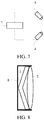
- the VR head-mounted apparatus of this application may further include a protective frame 8 as shown in FIG. 8 .
- the protective frame 8 may form an accommodating space adapted to the partial-reflection partial-transmission lens 3 and the convex lens 2, so as to accommodate and fix the partial-reflection partial-transmission lens 3 and the convex lens 2, thereby improving the structural integrity and stability.
- first, second, and third may be used herein to describe various information, such information should not be limited to these terms. These terms are merely used for distinguishing information of the same type from each other.
- first information may also be referred to as second information, and similarly, second information may also be referred to as first information.
- second information may also be referred to as first information.
- the term “if' as used herein may be interpreted as "when " or “upon " or "in response to determining.”
Landscapes
- Physics & Mathematics (AREA)
- Engineering & Computer Science (AREA)
- General Physics & Mathematics (AREA)
- Optics & Photonics (AREA)
- General Engineering & Computer Science (AREA)
- Theoretical Computer Science (AREA)
- Human Computer Interaction (AREA)
- User Interface Of Digital Computer (AREA)
- Position Input By Displaying (AREA)
- Studio Devices (AREA)
Abstract
Description
- This application relates to the technical field of virtual reality, and in particular, to a virtual reality head-mounted apparatus.
- Virtual reality (VR) technology is a technology that comprehensively utilizes a computer graphics system and various control interfaces to generate an interactive three-dimensional interaction environment on a computer to provide users with immersive experience. In related art, a user can wear a VR head-mounted apparatus, such as VR glasses, a VR helmet, or another VR apparatus, to obtain corresponding VR experience.
- Due to unique characteristics of VR scenarios, technical solutions for traditional electronic devices such as mobile phones or PCs may not be applicable to VR scenarios. For example, to acquire an infrared image of an eye of a user wearing a VR apparatus, due to structural limitations within the VR apparatus, image acquisition conditions for conventional methods may be difficult to meet, resulting in difficulties to successfully complete the corresponding tasks such as biometric recognition, eye tracking, etc.
- In view of these limitations, this application provides a VR head-mounted apparatus, which can improve the acquisition accuracy of an infrared image of an eye of a user.
- To achieve the foregoing objective, this application provides the following technical solutions.
- According to a first aspect of this application, a VR head-mounted apparatus is provided, including:
- a main body, the main body being provided with a convex lens; and
- a camera and a partial-reflection partial-transmission lens for reflecting infrared light provided in the main body, the partial-reflection partial-transmission lens being located on a side of the convex lens closer to a user, and a lens surface of the partial-reflection partial-transmission lens being disposed obliquely to reflect an infrared image of an eye of the user obliquely to the camera.
- Optionally, the partial-reflection partial-transmission lens has a high transmittance for visible light and a low transmittance for infrared light.
- Optionally, the partial-reflection partial-transmission lens includes an infrared dichroic mirror.
- Optionally, the camera is located outside a visible area of the convex lens with respect to the user.
- Optionally, the partial-reflection partial-transmission lens has a plate shape, the lens surface of the partial-reflection partial-transmission lens is inclined upward, the camera is located at a top of the main body, and a lens of the camera is disposed obliquely downward.
- Optionally, the partial-reflection partial-transmission lens has a plate shape, the lens surface of the partial-reflection partial-transmission lens is inclined downward, the camera is located at a bottom of the main body, and a lens of the camera is disposed obliquely upward.
- Optionally, the partial-reflection partial-transmission lens includes an upper lens structure and a lower lens structure disposed obliquely, and a joint of the upper lens structure and the lower lens structure faces the user; the main body is provided with a first camera and a second camera, the first camera is located at a top of the main body and a lens of the first camera is disposed obliquely downward corresponding to the upper lens structure, and the second camera is located at a bottom of the main body and a lens of the second camera is disposed obliquely upward corresponding to the lower lens structure.
- Optionally, the upper lens structure and the lower lens structure are symmetrical with respect to a horizontal plane.
- Optionally, the apparatus further includes:
a protective frame, the protective frame forming an accommodating space adapted to the partial-reflection partial-transmission lens and the convex lens, so as to accommodate and fix the partial-reflection partial-transmission lens and the convex lens. - Optionally, the apparatus further includes:
an adjustment component, the adjustment component performing angle adjustment on the camera, such that the lens of the camera is kept toward a virtual image of the infrared image of the eye formed in the partial-reflection partial-transmission lens. - As can be seen from the above technical solutions, in this application, a partial-reflection partial-transmission lens is provided in a VR head-mounted apparatus, and a lens surface of the partial-reflection partial-transmission lens is disposed obliquely. Without interfering with a user's viewing of VR display content, by obliquely reflecting an infrared image of an eye of the user, a deviation angle of a camera during the acquisition of the infrared image of the eye can be reduced, thus reducing the deformation and distortion of the infrared image of the eye, and helping to improve the acquisition accuracy for the infrared image of the eye.
-
-
FIG. 1 is a side cross-sectional view of a VR helmet provided by a first exemplary embodiment of this application. -
FIG. 2 is a side cross-sectional view of a VR helmet provided by a second exemplary embodiment of this application. -
FIG. 3 is a side cross-sectional view of a VR helmet provided by a third exemplary embodiment of this application. -
FIGS. 4-6 are side cross-sectional views of a VR helmet provided by a fourth exemplary embodiment of this application. -
FIG. 7 is a schematic view of controlling an angle of a camera provided by an exemplary embodiment of this application. -
FIG. 8 is a schematic view of providing a partial-reflection partial-transmission lens and a convex lens through a protective frame provided by an exemplary embodiment of this application. - In order to further explain this application, the following embodiments are provided, using a VR helmet as an example, to introduce the related structure of a VR head-mounted apparatus of this application.
-
FIG. 1 is a side cross-sectional view of a VR helmet provided by an exemplary embodiment of this application. As shown inFIG. 1 , the VR helmet may include: amain body 1, themain body 1 being provided with aconvex lens 2 and aVR playing component 5. Further, themain body 1 is further provided with a partial-reflection partial-transmission lens 3 for reflecting infrared light. The partial-reflection partial-transmission lens 3 is located on a side of theconvex lens 2 closer to a user (i.e., the partial-reflection partial-transmission lens 3 is located between theconvex lens 2 and aneye 6 of the user). Since the partial-reflection partial-transmission lens 3 has a high transmittance for visible light (relative to infrared light) and a low transmittance for infrared light (relative to visible light), VR display content played by theVR playing component 5 may, in a form of visible light S1, go through the partial-reflection partial-transmission lens 3 almost unaffected, and theeye 6 of the user receives thevisible light S 1 to view of the VR display content, while infrared light S2 emitted from theeye 6 of the user is mostly or almost completely reflected by the partial-reflection partial-transmission lens 3. Corresponding reflected infrared light S2' is acquired by acamera 4 provided in themain body 1, and an infrared image of theeye 6 may be formed from the reflected infrared light S2' to achieve functions such as eye tracking and iris recognition. - More specifically, a
lens surface 30 of the partial-reflection partial-transmission lens 3 is disposed obliquely, and positions of the partial-reflection partial-transmission lens 3 and thecamera 4 correspond to each other, such that thelens surface 30 of the partial-reflection partial-transmission lens 3 can obliquely reflect the infrared light S2 corresponding to the infrared image of theeye 6 toward thecamera 4. For example, in the embodiment shown inFIG. 1 , thecamera 4 may be located at a lower edge of themain body 1 close to a user side (i.e., left side inFIG. 1 ), and a lens of thecamera 4 faces inward toward the partial-reflection partial-transmission lens 3 to acquire the foregoing reflected infrared light S2'. Then, assuming that an angle between thecamera 4 and the infrared light S2 is maintained at α, since thelens surface 30 of the partial-reflection partial-transmission lens 3 is disposed obliquely to reflect the infrared light S2 toward thecamera 4 to form the reflected infrared light S2', an angle β between thecamera 4 and the reflected infrared light S2' is inevitably smaller than the foregoing angle α. Thus possible deformation and distortion of the infrared image of the eye acquired by thecamera 4 may be reduced, which helps to improve the acquisition accuracy for the infrared image of theeye 6, and to further improve the accuracy and precision of subsequent processing such as iris recognition and eye tracking. - Moreover, since the
eye 6 of the user tends to be smaller than theconvex lens 2, a visible area formed between theeye 6 and theconvex lens 2 may have a trapezoidal shape as shown inFIG. 1 (the cross section is trapezoidal; in fact, since theconvex lens 2 is round, a 3-D shape corresponding to the visible area is approximately a cone), and a top surface and a bottom surface of themain body 1 are planar. Then, in an example that thecamera 4 is located inside an edge of the bottom surface of themain body 1, it is obvious that an installation space for thecamera 4 is smaller as the camera moves closer to theconvex lens 2 and the installation space for thecamera 4 is larger as the camera moves closer to theeye 6. So, when an installation position of thecamera 4 is close to the eye 6 (e.g., in the embodiment shown inFIG. 1 ), a larger installation space (compared to a situation where the installation position of thecamera 4 is close to the convex lens 2) can be obtained to adjust an installation angle of the camera 4 (e.g., to make it more parallel with the reflected infrared light S2') and reduce the foregoing angle β, thereby improving the acquisition accuracy of thecamera 4 for the infrared image of theeye 6. - It should be noted that the technical solutions of this application may be applied to any type of VR head-mounted apparatus. For example, as shown in
FIG. 1 , the VR helmet may be an integrated-style VR head-mounted apparatus, that is, the VR helmet may independently implement a VR playing function without resorting to an external apparatus. TheVR playing component 5 is pre-built in the VR helmet to implement playing functions such as rendering and displaying of VR display content. Alternatively, the VR helmet may be a split-style VR head-mounted apparatus. For example, when the VR helmet apparatus is paired with a mobile apparatus such as a mobile phone or a tablet, theVR playing component 5 may include a mobile apparatus installed in the VR helmet, and the mobile apparatus may implement rendering through a processor, a graphics card chip, etc., and may perform content display through a screen component. For another example, when the VR helmet is paired with a PC host, a game console, or another external apparatus, theVR playing component 5 may be a display component built in the VR helmet, and the foregoing external apparatus is used to render VR display content and the like. - In the technical solutions of this application, the partial-reflection partial-
transmission lens 3 for reflecting infrared light refers to a lens having a low transmittance for an infrared spectrum and a high transmittance for other spectra such as visible light. By blocking the low-transmittance infrared spectrum as much as possible, the partial-reflection partial-transmission lens 3 reflects the infrared spectrum, i.e., "partial-reflection." Meanwhile, other spectra such as high-transmittance visible light can be transmitted through the partial-reflection partial-transmission lens 3 as much as possible, so that the partial-reflection partial-transmission lens 3's blocking or impact on other spectra such as the visible light can be minimized, i.e., "partial-transmission". - For example, the foregoing partial-reflection partial-
transmission lens 3 for reflecting infrared light may be an infrared dichroic mirror, such that a visible spectrum may be almost completely transmitted and an infrared spectrum may be almost completely reflected. Specifically, in one case, an infrared reflective film such as a TiO2-Ag-TiO2 infrared reflective film or a ZnS-Ag-ZnS infrared reflective film may be coated on a surface of an optical lens that has a high transmittance for visible light (the visible spectrum may be almost completely transmitted) to form the infrared dichroic mirror. In another case, a lens may be made based entirely on materials in the foregoing infrared reflective film or a similar preparation material to form the infrared dichroic mirror. - As can be seen from the above technical solutions, in this application, a partial-reflection partial-
transmission lens 3 is provided in a VR head-mounted apparatus, and alens surface 30 of the partial-reflection partial-transmission lens 3 is disposed obliquely. Without interfering with a user's viewing of VR display content, an infrared image of an eye of the user is obliquely reflected, and a deviation angle of acamera 4 during the acquisition of the infrared image of the eye can be reduced, thus reducing the deformation and distortion of the infrared image of the eye, and helping to improve the acquisition accuracy for the infrared image of the eye. - In the technical solutions of this application, when the partial-reflection partial-
transmission lens 3 has a plate shape as shown inFIG. 1 , thelens 3 as a whole may be arranged obliquely, as shown inFIG. 1 . In other embodiments, thelens surface 30 may be inclined in other manners. For example, as shown inFIG. 2 , when the partial-reflection partial-transmission lens 3 has a wedge-shaped cross section, a bottom surface of the partial-reflection partial-transmission lens 3 is in a vertical direction, and thelens surface 30 is inclined, thereby helping to reduce the installation difficulty of the partial-reflection partial-transmission lens 3 as the installation angle of the partial-reflection partial-transmission lens 3 does not need to be repeatedly adjusted. - Due to the structural characteristics of a human eye, when the embodiment shown in
FIG. 1 or FIG. 2 is utilized, i.e., thelens surface 30 of the partial-reflection partial-transmission lens 3 is inclined downward, thecamera 4 is located at a bottom of themain body 1, and the lens of thecamera 4 is disposed obliquely upward, the infrared image of theeye 6 of the user can be acquired more completely, clearly and accurately under the same conditions. Certainly, if the embodiment as shown inFIG. 3 is utilized, that is, thelens surface 30 of the partial-reflection partial-transmission lens 3 is inclined upward, thecamera 4 is located at a top of themain body 1, and the lens of thecamera 4 is disposed obliquely downward, the infrared image of theeye 6 can also be obtained. -
FIG. 4 is a side cross-sectional view of a VR helmet provided by an exemplary embodiment of this application. As shown inFIG. 4 , in addition to the foregoing plate structure shown inFIGS. 1-3 , the partial-reflection partial-transmission lens 3 may have other structures. For example, the partial-reflection partial-transmission lens 3 inFIG. 4 may include anupper lens structure 3A and alower lens structure 3B disposed obliquely, and a joint of theupper lens structure 3A and thelower lens structure 3B faces the user (i.e., in the embodiment shown inFIG. 4 , theupper lens structure 3A has its lower part inclined leftward and its upper part inclined rightward, and thelower lens structure 3B has its upper part inclined leftwards and its lower part inclined rightwards). - Meanwhile, the
main body 1 is provided with afirst camera 4A and asecond camera 4B. Thefirst camera 4A is located at the top of themain body 1 and a lens of thefirst camera 4A is disposed obliquely downward corresponding to theupper lens structure 3A, and thesecond camera 4B is located at the bottom of themain body 1 and a lens of thesecond camera 4B is disposed obliquely upward corresponding to thelower lens structure 3B. - In fact, since users wearing the VR apparatus may have different shapes and sizes on traits such as their heads, faces and eyes, and the VR apparatus is uniformly manufactured by a manufacturer, a positional relationship between the
eye 6 and the partial-reflection partial-transmission lens 3 may be different for different users wearing a same VR apparatus. For example, theeye 6 may not be exactly located in a middle position of themain body 1 as shown inFIGS. 1-3 , which may result in thecamera 4 not being able to completely acquire the infrared image of the eye of the user. - Then, to address the foregoing potential problems, this application, through the embodiments such as those shown in
FIG. 4 , can ensure that infrared images of the eyes of a user can be completely acquired by thefirst camera 4A and thesecond camera 4B, regardless the positional changes, such as an upward shift or a downward shift, that may occur to the eyes of the user. - For example, when the
eye 6 is located near the middle position of themain body 1, an upper region of the infrared image of theeye 6 corresponds to a first infrared ray S21, and a lower region corresponds to a first infrared ray S22. The first infrared ray S21 can be reflected by anupper lens surface 30A of theupper lens structure 3A to form a first reflected infrared ray S21', which may be acquired by thefirst camera 4A. The second infrared ray S22 can be reflected by alower lens surface 30B of thelower lens structure 3B to form a second reflected infrared ray S22', which may be acquired by thesecond camera 4B. Then, the first reflected infrared ray S21' and the second reflected infrared ray S22' can be combined to obtain the infrared image of theeye 6. - For another example, when the
eye 6 is shifted upward, as shown inFIG. 5 , the first infrared ray S21 and the first infrared ray S22 may both be emitted toward theupper lens structure 3A and reflected by theupper lens surface 30A of theupper lens structure 3A to form the first reflected infrared ray S21' and the second reflected infrared ray S22'. Thefirst camera 4A may acquire the first reflected infrared ray S21' and the second reflected infrared ray S22', and combined them to form the infrared image of theeye 6. - For another example, when the
eye 6 is shifted downward, as shown inFIG. 6 , the first infrared ray S21 and the first infrared ray S22 may both be emitted toward thelower lens structure 3B and reflected by thelower lens surface 30B of thelower lens structure 3B to obtain the first reflected infrared ray S21' and the second reflected infrared ray S22', Thesecond camera 4B may acquire the first reflected infrared ray S21' and the second reflected infrared ray S22', and combine them to form the infrared image of theeye 6. - In one embodiment, the
upper lens structure 3A and thelower lens structure 3B of the partial-reflection partial-transmission lens 3 shown inFIGS. 4-6 may be symmetrical with respect to a horizontal plane, such that theupper lens structure 3A and thelower lens structure 3B have the same or similar structural strength and stability, and the partial-reflection partial-transmission lens 3 has better overall stability. Certainly, in another embodiment, theupper lens structure 3A and thelower lens structure 3B may also have an asymmetric structure. For example, a largerlower lens structure 3B is utilized for the acquisition of an infrared image of an eye in most cases, and a smallerupper lens structure 3A is utilized for the acquisition of an infrared image of an eye in rare cases where theeye 6 of the user is shifted upward. - Certainly, in addition to using a specially-shaped partial-reflection partial-
transmission lens 3, as shown in the embodiments inFIGS. 4-6 , to adapt to different users, this application also provides other processing methods. For example, as shown inFIG. 7 , the VR head-mounted apparatus of this application may further include an adjustment component 7. The adjustment component 7 is electrically connected to eachcamera 4 to perform angle adjustment on thecamera 4, such that the lens of thecamera 4 is kept toward a virtual image of the infrared image of the eye formed in the partial-reflection partial-transmission lens 3, thereby obtaining a complete, clear and accurate infrared image of the eye. - In addition, in the technical solutions of this application, since the partial-reflection partial-
transmission lens 3 is added compared to the related art as shown inFIG. 1 , the VR head-mounted apparatus of this application may further include aprotective frame 8 as shown inFIG. 8 . Theprotective frame 8 may form an accommodating space adapted to the partial-reflection partial-transmission lens 3 and theconvex lens 2, so as to accommodate and fix the partial-reflection partial-transmission lens 3 and theconvex lens 2, thereby improving the structural integrity and stability. - It should also be noted that the terms "include", "comprise" and any other variants mean to cover the non-exclusive inclusion. Thereby, the process, method, article, or device which include a series of elements not only include those elements, but also include other elements which are not clearly listed, or include the inherent elements of the process, method, article and device. Without further limitation, the element defined by a phrase "include one......" does not exclude other same elements in the process, method, article or device which include the element.
- Reference will now be made in detail to exemplary embodiments, examples of which are illustrated in the accompanying drawings. The following description refers to the accompanying drawings in which the same numbers in different drawings represent the same or similar elements unless otherwise represented. The implementations set forth in the following description of exemplary embodiments do not represent all implementations consistent with this application. Instead, they are merely examples of apparatuses and methods consistent with aspects related to this application as recited in the appended claims.
- The terms used in this application are merely for the purpose of describing specific embodiments, and are not intended to limit this application. The terms "a", "said" and "the" of singular forms used in this application and the appended claims are also intended to include plural forms, unless otherwise specified in the context clearly. It should also be understood that, the term "and/or" used herein indicates and includes any or all possible combinations of one or more associated listed items.
- It should be understood that although the terms such as first, second, and third may be used herein to describe various information, such information should not be limited to these terms. These terms are merely used for distinguishing information of the same type from each other. For example, within the scope of this application, first information may also be referred to as second information, and similarly, second information may also be referred to as first information. Depending on the context, the term "if' as used herein may be interpreted as "when ..." or "upon ..." or "in response to determining."
- The foregoing descriptions are merely exemplary embodiments of this application, but are not intended to limit this application. Any modification, equivalent replacement, or improvement made without departing from the spirit and principle of this application should fall within the protection scope of this application.
Claims (10)
- A virtual reality head-mounted apparatus, comprising:a main body, the main body being provided with a convex lens; anda camera and a partial-reflection partial-transmission lens for reflecting infrared light provided in the main body, the partial-reflection partial-transmission lens being located on a side of the convex lens closer to a user, and a lens surface of the partial-reflection partial-transmission lens being disposed obliquely to reflect an infrared image of an eye of the user obliquely to the camera.
- The apparatus according to claim 1, wherein the partial-reflection partial-transmission lens has a high transmittance for visible light and a low transmittance for infrared light.
- The apparatus according to claim 1, wherein the partial-reflection partial-transmission lens comprises an infrared dichroic mirror.
- The apparatus according to claim 1, wherein the camera is located outside a visible area of the convex lens with respect to the user.
- The apparatus according to claim 1, wherein the partial-reflection partial-transmission lens has a plate shape, the lens surface of the partial-reflection partial-transmission lens is inclined upward, the camera is located at a top of the main body, and a lens of the camera is disposed obliquely downward.
- The apparatus according to claim 1, wherein the partial-reflection partial-transmission lens has a plate shape, the lens surface of the partial-reflection partial-transmission lens is inclined downward, the camera is located at a bottom of the main body, and a lens of the camera is disposed obliquely upward.
- The apparatus according to claim 1, wherein the partial-reflection partial-transmission lens comprises an upper lens structure and a lower lens structure disposed obliquely, and a joint of the upper lens structure and the lower lens structure faces the user; the main body is provided with a first camera and a second camera, the first camera is located at a top of the main body and a lens of the first camera is disposed obliquely downward corresponding to the upper lens structure, and the second camera is located at a bottom of the main body and a lens of the second camera is disposed obliquely upward corresponding to the lower lens structure.
- The apparatus according to claim 7, wherein the upper lens structure and the lower lens structure are symmetrical with respect to a horizontal plane.
- The apparatus according to claim 1, further comprising:
a protective frame, the protective frame forming an accommodating space adapted to the partial-reflection partial-transmission lens and the convex lens, so as to accommodate and fix the partial-reflection partial-transmission lens and the convex lens. - The apparatus according to claim 1, further comprising:
an adjustment component, the adjustment component performing angle adjustment on the camera, such that the lens of the camera is kept toward a virtual image of the infrared image of the eye formed in the partial-reflection partial-transmission lens.
Priority Applications (1)
| Application Number | Priority Date | Filing Date | Title |
|---|---|---|---|
| PL18758081T PL3557308T3 (en) | 2017-02-27 | 2018-02-26 | Virtual reality head-mounted apparatus |
Applications Claiming Priority (2)
| Application Number | Priority Date | Filing Date | Title |
|---|---|---|---|
| CN201710109486.6A CN106908951A (en) | 2017-02-27 | 2017-02-27 | Virtual reality helmet |
| PCT/CN2018/077285 WO2018153371A1 (en) | 2017-02-27 | 2018-02-26 | Virtual reality head-mounted apparatus |
Publications (3)
| Publication Number | Publication Date |
|---|---|
| EP3557308A1 true EP3557308A1 (en) | 2019-10-23 |
| EP3557308A4 EP3557308A4 (en) | 2020-01-29 |
| EP3557308B1 EP3557308B1 (en) | 2020-08-26 |
Family
ID=59208362
Family Applications (1)
| Application Number | Title | Priority Date | Filing Date |
|---|---|---|---|
| EP18758081.6A Active EP3557308B1 (en) | 2017-02-27 | 2018-02-26 | Virtual reality head-mounted apparatus |
Country Status (12)
| Country | Link |
|---|---|
| US (1) | US11442270B2 (en) |
| EP (1) | EP3557308B1 (en) |
| JP (1) | JP6856863B2 (en) |
| KR (1) | KR102284974B1 (en) |
| CN (1) | CN106908951A (en) |
| ES (1) | ES2824820T3 (en) |
| MY (1) | MY193942A (en) |
| PH (1) | PH12019501661B1 (en) |
| PL (1) | PL3557308T3 (en) |
| SG (1) | SG11201906874WA (en) |
| TW (1) | TWI659229B (en) |
| WO (1) | WO2018153371A1 (en) |
Families Citing this family (8)
| Publication number | Priority date | Publication date | Assignee | Title |
|---|---|---|---|---|
| CN106908951A (en) * | 2017-02-27 | 2017-06-30 | 阿里巴巴集团控股有限公司 | Virtual reality helmet |
| CN110850594B (en) * | 2018-08-20 | 2022-05-17 | 余姚舜宇智能光学技术有限公司 | Head-mounted visual equipment and eyeball tracking system for same |
| US11442243B2 (en) | 2019-11-07 | 2022-09-13 | Htc Corporation | Head mounted display device |
| US20230316692A1 (en) * | 2020-09-14 | 2023-10-05 | Hewlett-Packard Development Company, L.P. | Head Mounted Display with Reflective Surface |
| CN116802632A (en) * | 2020-09-25 | 2023-09-22 | 苹果公司 | Systems and methods for user authentication devices |
| EP4202531A4 (en) | 2020-11-24 | 2024-03-20 | Samsung Electronics Co., Ltd. | Augmented reality wearable electronic device comprising camera |
| CN117310972A (en) * | 2022-06-21 | 2023-12-29 | 北京七鑫易维信息技术有限公司 | An eye-tracking optical device, system and virtual reality device |
| CN116719165A (en) * | 2023-06-08 | 2023-09-08 | 业桓科技(成都)有限公司 | Head-mounted display and near-eye display method |
Family Cites Families (76)
| Publication number | Priority date | Publication date | Assignee | Title |
|---|---|---|---|---|
| US4227113A (en) * | 1978-10-18 | 1980-10-07 | Duro-Test Corporation | Incandescent electric lamp with partial light transmitting coating |
| US5621424A (en) * | 1992-08-24 | 1997-04-15 | Olympus Optical Co., Ltd. | Head mount display apparatus allowing easy switching operation from electronic image to external field image |
| JPH06121254A (en) * | 1992-10-06 | 1994-04-28 | Olympus Optical Co Ltd | Head mount type display device |
| US5347400A (en) | 1993-05-06 | 1994-09-13 | Ken Hunter | Optical system for virtual reality helmet |
| US6018630A (en) * | 1994-05-17 | 2000-01-25 | Canon Kabushiki Kaisha | Camera viewfinder having a viewpoint detecting apparatus |
| US7262919B1 (en) * | 1994-06-13 | 2007-08-28 | Canon Kabushiki Kaisha | Head-up display device with curved optical surface having total reflection |
| JP3309615B2 (en) * | 1994-12-21 | 2002-07-29 | キヤノン株式会社 | Image observation apparatus and binocular image observation apparatus using the same |
| JPH09274144A (en) * | 1996-04-02 | 1997-10-21 | Canon Inc | Image display device |
| US5771124A (en) * | 1996-07-02 | 1998-06-23 | Siliscape | Compact display system with two stage magnification and immersed beam splitter |
| US5689619A (en) | 1996-08-09 | 1997-11-18 | The United States Of America As Represented By The Secretary Of The Army | Eyetracker control of heads-up displays |
| US6043799A (en) * | 1998-02-20 | 2000-03-28 | University Of Washington | Virtual retinal display with scanner array for generating multiple exit pupils |
| JPH11249588A (en) * | 1998-02-27 | 1999-09-17 | Shimadzu Corp | Head mounted display |
| US6433760B1 (en) | 1999-01-14 | 2002-08-13 | University Of Central Florida | Head mounted display with eyetracking capability |
| WO2005111693A1 (en) | 2004-05-17 | 2005-11-24 | Olympus Corporation | Head-mounted type image display device |
| CN101243392A (en) | 2005-08-15 | 2008-08-13 | 皇家飞利浦电子股份有限公司 | Systems, devices and methods for end-user programmed augmented reality glasses |
| US7522344B1 (en) * | 2005-12-14 | 2009-04-21 | University Of Central Florida Research Foundation, Inc. | Projection-based head-mounted display with eye-tracking capabilities |
| CN200994790Y (en) * | 2006-12-19 | 2007-12-26 | 潘晓刚 | System for measuring mental state parameter |
| JP2008165063A (en) | 2006-12-28 | 2008-07-17 | Scalar Corp | Head mounted display |
| CN101077232A (en) * | 2007-06-07 | 2007-11-28 | 南京航空航天大学 | Human-computer interaction helmet for type computer |
| JP5031452B2 (en) * | 2007-06-20 | 2012-09-19 | キヤノン株式会社 | Image observation apparatus and image observation system |
| WO2009150747A1 (en) * | 2008-06-13 | 2009-12-17 | パイオニア株式会社 | Sight line input user interface unit, user interface method, user interface program, and recording medium with user interface program recorded |
| JP5402293B2 (en) | 2009-06-22 | 2014-01-29 | ソニー株式会社 | Head-mounted display and image display method in head-mounted display |
| US20120249797A1 (en) | 2010-02-28 | 2012-10-04 | Osterhout Group, Inc. | Head-worn adaptive display |
| US9285589B2 (en) | 2010-02-28 | 2016-03-15 | Microsoft Technology Licensing, Llc | AR glasses with event and sensor triggered control of AR eyepiece applications |
| US8482859B2 (en) | 2010-02-28 | 2013-07-09 | Osterhout Group, Inc. | See-through near-eye display glasses wherein image light is transmitted to and reflected from an optically flat film |
| US20120194418A1 (en) | 2010-02-28 | 2012-08-02 | Osterhout Group, Inc. | Ar glasses with user action control and event input based control of eyepiece application |
| WO2011106797A1 (en) | 2010-02-28 | 2011-09-01 | Osterhout Group, Inc. | Projection triggering through an external marker in an augmented reality eyepiece |
| CN202198569U (en) * | 2011-08-09 | 2012-04-25 | 中国人民解放军空军航空医学研究所 | Side reverse type eye movement detector |
| US9019614B2 (en) | 2011-10-26 | 2015-04-28 | Google Inc. | Display device with image depth simulation |
| JP6141584B2 (en) * | 2012-01-24 | 2017-06-07 | アリゾナ ボード オブ リージェンツ オン ビハーフ オブ ザ ユニバーシティ オブ アリゾナ | Compact line-of-sight head-mounted display |
| EP2808725B1 (en) | 2012-01-24 | 2018-09-26 | Sony Corporation | Head-mounted display device with a light-shielding member |
| US9788714B2 (en) | 2014-07-08 | 2017-10-17 | Iarmourholdings, Inc. | Systems and methods using virtual reality or augmented reality environments for the measurement and/or improvement of human vestibulo-ocular performance |
| US9737209B2 (en) * | 2013-05-15 | 2017-08-22 | The Johns Hopkins University | Eye tracking and gaze fixation detection systems, components and methods using polarized light |
| US9625723B2 (en) * | 2013-06-25 | 2017-04-18 | Microsoft Technology Licensing, Llc | Eye-tracking system using a freeform prism |
| EP2821839A1 (en) * | 2013-07-03 | 2015-01-07 | Airbus Defence and Space GmbH | HMD device with adjustable eye tracking device |
| JP6175945B2 (en) * | 2013-07-05 | 2017-08-09 | ソニー株式会社 | Gaze detection apparatus and gaze detection method |
| US9494800B2 (en) * | 2014-01-21 | 2016-11-15 | Osterhout Group, Inc. | See-through computer display systems |
| US9330302B2 (en) * | 2014-02-26 | 2016-05-03 | Microsoft Technology Licensing, Llc | Polarized gaze tracking |
| KR20160143749A (en) * | 2014-04-09 | 2016-12-14 | 쓰리엠 이노베이티브 프로퍼티즈 컴파니 | Head mounted display and low conspicuity pupil illuminator |
| US9551873B2 (en) | 2014-05-30 | 2017-01-24 | Sony Interactive Entertainment America Llc | Head mounted device (HMD) system having interface with mobile computing device for rendering virtual reality content |
| US10445573B2 (en) * | 2014-06-27 | 2019-10-15 | Fove, Inc. | Gaze detection device |
| CN104407440A (en) * | 2014-11-19 | 2015-03-11 | 东南大学 | Holographic display device with sight tracking function |
| US9791924B2 (en) | 2014-12-23 | 2017-10-17 | Mediatek Inc. | Eye tracking with mobile device in a head-mounted display |
| JP5824697B1 (en) * | 2014-12-27 | 2015-11-25 | 株式会社Fove | Head mounted display |
| DK179537B1 (en) * | 2015-02-04 | 2019-02-08 | Itu Business Development A/S | Tin traces and eye tracking methods |
| KR101883090B1 (en) * | 2015-04-01 | 2018-07-27 | 포브, 아이엔씨. | Head mounted display |
| US9823474B2 (en) * | 2015-04-02 | 2017-11-21 | Avegant Corp. | System, apparatus, and method for displaying an image with a wider field of view |
| US20160378176A1 (en) * | 2015-06-24 | 2016-12-29 | Mediatek Inc. | Hand And Body Tracking With Mobile Device-Based Virtual Reality Head-Mounted Display |
| CN105093532A (en) | 2015-08-03 | 2015-11-25 | 京东方科技集团股份有限公司 | Virtual reality glasses and display method |
| CN205103761U (en) * | 2015-08-03 | 2016-03-23 | 众景视界(北京)科技有限公司 | Head -wearing type intelligent device |
| CN205051824U (en) | 2015-10-21 | 2016-02-24 | 北京小鸟看看科技有限公司 | Virtual reality glasses |
| WO2017091477A1 (en) * | 2015-11-25 | 2017-06-01 | Google Inc. | Prism-based eye tracking |
| US9880384B2 (en) * | 2015-11-27 | 2018-01-30 | Fove, Inc. | Gaze detection system, gaze point detection method, and gaze point detection program |
| US10303246B2 (en) * | 2016-01-20 | 2019-05-28 | North Inc. | Systems, devices, and methods for proximity-based eye tracking |
| CN106214118A (en) * | 2016-01-28 | 2016-12-14 | 北京爱生科贸有限公司 | A kind of ocular movement based on virtual reality monitoring system |
| US10401952B2 (en) * | 2016-03-31 | 2019-09-03 | Sony Interactive Entertainment Inc. | Reducing rendering computation and power consumption by detecting saccades and blinks |
| US10192528B2 (en) * | 2016-03-31 | 2019-01-29 | Sony Interactive Entertainment Inc. | Real-time user adaptive foveated rendering |
| US10169846B2 (en) * | 2016-03-31 | 2019-01-01 | Sony Interactive Entertainment Inc. | Selective peripheral vision filtering in a foveated rendering system |
| CN205594581U (en) * | 2016-04-06 | 2016-09-21 | 北京七鑫易维信息技术有限公司 | Module is tracked to eyeball of video glasses |
| CN106406509B (en) * | 2016-05-16 | 2023-08-01 | 上海青研科技有限公司 | Head-mounted eye-control virtual reality equipment |
| CN205721634U (en) * | 2016-05-16 | 2016-11-23 | 上海青研科技有限公司 | A kind of wear-type eye control virtual reality device |
| CN105955491B (en) * | 2016-06-30 | 2020-07-10 | 北京上古视觉科技有限公司 | VR glasses with eye accuse and iris recognition function |
| CN205942608U (en) * | 2016-06-30 | 2017-02-08 | 上海青研科技有限公司 | A integration mirror cup that is used for eyeball to track and iris discernment |
| DE202016104179U1 (en) * | 2016-07-29 | 2016-08-12 | Christian Hildebrandt | Output device for stereoscopic image reproduction |
| US20180068449A1 (en) * | 2016-09-07 | 2018-03-08 | Valve Corporation | Sensor fusion systems and methods for eye-tracking applications |
| CN106406543A (en) * | 2016-11-23 | 2017-02-15 | 长春中国光学科学技术馆 | VR scene conversion device controlled by human eyes |
| US20180157320A1 (en) * | 2016-12-01 | 2018-06-07 | Oculus Vr, Llc | Air spaced optical assembly with integrated eye tracking |
| US10310598B2 (en) * | 2017-01-17 | 2019-06-04 | Facebook Technologies, Llc | Varifocal head-mounted display including modular air spaced optical assembly |
| US10485420B2 (en) * | 2017-02-17 | 2019-11-26 | Analog Devices Global Unlimited Company | Eye gaze tracking |
| CN206584118U (en) * | 2017-02-27 | 2017-10-24 | 阿里巴巴集团控股有限公司 | Virtual reality helmet |
| CN106908951A (en) * | 2017-02-27 | 2017-06-30 | 阿里巴巴集团控股有限公司 | Virtual reality helmet |
| US10546518B2 (en) * | 2017-05-15 | 2020-01-28 | Google Llc | Near-eye display with extended effective eyebox via eye tracking |
| US10627627B2 (en) * | 2017-10-02 | 2020-04-21 | Google Llc | Eye tracking using light guide with faceted combiner |
| US10788677B2 (en) * | 2017-10-03 | 2020-09-29 | Facebook Technologies, Llc | Fresnel assembly for light redirection in eye tracking systems |
| US10488917B2 (en) * | 2018-02-17 | 2019-11-26 | Varjo Technologies Oy | Gaze-tracking system and method of tracking user's gaze using reflective element |
| US10788892B2 (en) * | 2018-05-23 | 2020-09-29 | Facebook Technologies, Llc | In-field illumination and imaging for eye tracking |
-
2017
- 2017-02-27 CN CN201710109486.6A patent/CN106908951A/en active Pending
- 2017-11-17 TW TW106139871A patent/TWI659229B/en not_active IP Right Cessation
-
2018
- 2018-02-26 ES ES18758081T patent/ES2824820T3/en active Active
- 2018-02-26 MY MYPI2019004078A patent/MY193942A/en unknown
- 2018-02-26 EP EP18758081.6A patent/EP3557308B1/en active Active
- 2018-02-26 KR KR1020197022644A patent/KR102284974B1/en active Active
- 2018-02-26 PH PH1/2019/501661A patent/PH12019501661B1/en unknown
- 2018-02-26 PL PL18758081T patent/PL3557308T3/en unknown
- 2018-02-26 JP JP2019546360A patent/JP6856863B2/en active Active
- 2018-02-26 WO PCT/CN2018/077285 patent/WO2018153371A1/en not_active Ceased
- 2018-02-26 SG SG11201906874WA patent/SG11201906874WA/en unknown
-
2019
- 2019-07-15 US US16/511,353 patent/US11442270B2/en active Active
Also Published As
| Publication number | Publication date |
|---|---|
| KR20190101445A (en) | 2019-08-30 |
| PH12019501661A1 (en) | 2020-03-02 |
| KR102284974B1 (en) | 2021-08-03 |
| US11442270B2 (en) | 2022-09-13 |
| SG11201906874WA (en) | 2019-08-27 |
| US20190339527A1 (en) | 2019-11-07 |
| PL3557308T3 (en) | 2021-01-25 |
| ES2824820T3 (en) | 2021-05-13 |
| JP6856863B2 (en) | 2021-04-14 |
| MY193942A (en) | 2022-11-02 |
| WO2018153371A1 (en) | 2018-08-30 |
| EP3557308B1 (en) | 2020-08-26 |
| CN106908951A (en) | 2017-06-30 |
| JP2020514887A (en) | 2020-05-21 |
| PH12019501661B1 (en) | 2024-04-17 |
| EP3557308A4 (en) | 2020-01-29 |
| TWI659229B (en) | 2019-05-11 |
| TW201831949A (en) | 2018-09-01 |
Similar Documents
| Publication | Publication Date | Title |
|---|---|---|
| EP3557308B1 (en) | Virtual reality head-mounted apparatus | |
| US10996477B2 (en) | Virtual reality head-mounted apparatus | |
| US11500607B2 (en) | Using detected pupil location to align optical components of a head-mounted display | |
| US11523039B2 (en) | Virtual reality head-mounted apparatus | |
| US20190349506A1 (en) | Virtual reality head-mounted apparatus | |
| CN206584118U (en) | Virtual reality helmet | |
| US12379614B2 (en) | Eyewear waveguide with reflector | |
| US12047551B2 (en) | Correction polarization compensation optic for display systems | |
| CN206573783U (en) | Virtual reality helmet | |
| KR20240145340A (en) | Electronic device and method for providing virtual space image | |
| HK1238726A1 (en) | Virtual reality head-mounted device | |
| HK1238346A1 (en) | Virtual reality head-mounted device | |
| HK1238346A (en) | Virtual reality head-mounted device |
Legal Events
| Date | Code | Title | Description |
|---|---|---|---|
| STAA | Information on the status of an ep patent application or granted ep patent |
Free format text: STATUS: THE INTERNATIONAL PUBLICATION HAS BEEN MADE |
|
| PUAI | Public reference made under article 153(3) epc to a published international application that has entered the european phase |
Free format text: ORIGINAL CODE: 0009012 |
|
| STAA | Information on the status of an ep patent application or granted ep patent |
Free format text: STATUS: REQUEST FOR EXAMINATION WAS MADE |
|
| 17P | Request for examination filed |
Effective date: 20190718 |
|
| AK | Designated contracting states |
Kind code of ref document: A1 Designated state(s): AL AT BE BG CH CY CZ DE DK EE ES FI FR GB GR HR HU IE IS IT LI LT LU LV MC MK MT NL NO PL PT RO RS SE SI SK SM TR |
|
| AX | Request for extension of the european patent |
Extension state: BA ME |
|
| STAA | Information on the status of an ep patent application or granted ep patent |
Free format text: STATUS: EXAMINATION IS IN PROGRESS |
|
| A4 | Supplementary search report drawn up and despatched |
Effective date: 20200108 |
|
| RIC1 | Information provided on ipc code assigned before grant |
Ipc: G02B 27/14 20060101ALI20191220BHEP Ipc: G02B 27/00 20060101ALI20191220BHEP Ipc: G06F 3/01 20060101ALI20191220BHEP Ipc: G02B 27/01 20060101AFI20191220BHEP |
|
| 17Q | First examination report despatched |
Effective date: 20200120 |
|
| DAV | Request for validation of the european patent (deleted) | ||
| DAX | Request for extension of the european patent (deleted) | ||
| GRAP | Despatch of communication of intention to grant a patent |
Free format text: ORIGINAL CODE: EPIDOSNIGR1 |
|
| STAA | Information on the status of an ep patent application or granted ep patent |
Free format text: STATUS: GRANT OF PATENT IS INTENDED |
|
| GRAS | Grant fee paid |
Free format text: ORIGINAL CODE: EPIDOSNIGR3 |
|
| GRAA | (expected) grant |
Free format text: ORIGINAL CODE: 0009210 |
|
| STAA | Information on the status of an ep patent application or granted ep patent |
Free format text: STATUS: THE PATENT HAS BEEN GRANTED |
|
| INTG | Intention to grant announced |
Effective date: 20200630 |
|
| AK | Designated contracting states |
Kind code of ref document: B1 Designated state(s): AL AT BE BG CH CY CZ DE DK EE ES FI FR GB GR HR HU IE IS IT LI LT LU LV MC MK MT NL NO PL PT RO RS SE SI SK SM TR |
|
| REG | Reference to a national code |
Ref country code: GB Ref legal event code: FG4D |
|
| REG | Reference to a national code |
Ref country code: CH Ref legal event code: EP |
|
| REG | Reference to a national code |
Ref country code: DE Ref legal event code: R096 Ref document number: 602018007326 Country of ref document: DE |
|
| REG | Reference to a national code |
Ref country code: AT Ref legal event code: REF Ref document number: 1306908 Country of ref document: AT Kind code of ref document: T Effective date: 20200915 |
|
| REG | Reference to a national code |
Ref country code: IE Ref legal event code: FG4D |
|
| REG | Reference to a national code |
Ref country code: CH Ref legal event code: NV Representative=s name: SERVOPATENT GMBH, CH |
|
| REG | Reference to a national code |
Ref country code: FI Ref legal event code: FGE |
|
| REG | Reference to a national code |
Ref country code: NL Ref legal event code: FP |
|
| REG | Reference to a national code |
Ref country code: LT Ref legal event code: MG4D |
|
| RAP2 | Party data changed (patent owner data changed or rights of a patent transferred) |
Owner name: ADVANCED NEW TECHNOLOGIES CO., LTD. |
|
| PG25 | Lapsed in a contracting state [announced via postgrant information from national office to epo] |
Ref country code: SE Free format text: LAPSE BECAUSE OF FAILURE TO SUBMIT A TRANSLATION OF THE DESCRIPTION OR TO PAY THE FEE WITHIN THE PRESCRIBED TIME-LIMIT Effective date: 20200826 Ref country code: GR Free format text: LAPSE BECAUSE OF FAILURE TO SUBMIT A TRANSLATION OF THE DESCRIPTION OR TO PAY THE FEE WITHIN THE PRESCRIBED TIME-LIMIT Effective date: 20201127 Ref country code: LT Free format text: LAPSE BECAUSE OF FAILURE TO SUBMIT A TRANSLATION OF THE DESCRIPTION OR TO PAY THE FEE WITHIN THE PRESCRIBED TIME-LIMIT Effective date: 20200826 Ref country code: HR Free format text: LAPSE BECAUSE OF FAILURE TO SUBMIT A TRANSLATION OF THE DESCRIPTION OR TO PAY THE FEE WITHIN THE PRESCRIBED TIME-LIMIT Effective date: 20200826 Ref country code: BG Free format text: LAPSE BECAUSE OF FAILURE TO SUBMIT A TRANSLATION OF THE DESCRIPTION OR TO PAY THE FEE WITHIN THE PRESCRIBED TIME-LIMIT Effective date: 20201126 Ref country code: PT Free format text: LAPSE BECAUSE OF FAILURE TO SUBMIT A TRANSLATION OF THE DESCRIPTION OR TO PAY THE FEE WITHIN THE PRESCRIBED TIME-LIMIT Effective date: 20201228 |
|
| REG | Reference to a national code |
Ref country code: NO Ref legal event code: T2 Effective date: 20200826 |
|
| REG | Reference to a national code |
Ref country code: AT Ref legal event code: MK05 Ref document number: 1306908 Country of ref document: AT Kind code of ref document: T Effective date: 20200826 |
|
| PG25 | Lapsed in a contracting state [announced via postgrant information from national office to epo] |
Ref country code: IS Free format text: LAPSE BECAUSE OF FAILURE TO SUBMIT A TRANSLATION OF THE DESCRIPTION OR TO PAY THE FEE WITHIN THE PRESCRIBED TIME-LIMIT Effective date: 20201226 Ref country code: LV Free format text: LAPSE BECAUSE OF FAILURE TO SUBMIT A TRANSLATION OF THE DESCRIPTION OR TO PAY THE FEE WITHIN THE PRESCRIBED TIME-LIMIT Effective date: 20200826 Ref country code: RS Free format text: LAPSE BECAUSE OF FAILURE TO SUBMIT A TRANSLATION OF THE DESCRIPTION OR TO PAY THE FEE WITHIN THE PRESCRIBED TIME-LIMIT Effective date: 20200826 |
|
| PG25 | Lapsed in a contracting state [announced via postgrant information from national office to epo] |
Ref country code: SM Free format text: LAPSE BECAUSE OF FAILURE TO SUBMIT A TRANSLATION OF THE DESCRIPTION OR TO PAY THE FEE WITHIN THE PRESCRIBED TIME-LIMIT Effective date: 20200826 Ref country code: CZ Free format text: LAPSE BECAUSE OF FAILURE TO SUBMIT A TRANSLATION OF THE DESCRIPTION OR TO PAY THE FEE WITHIN THE PRESCRIBED TIME-LIMIT Effective date: 20200826 Ref country code: DK Free format text: LAPSE BECAUSE OF FAILURE TO SUBMIT A TRANSLATION OF THE DESCRIPTION OR TO PAY THE FEE WITHIN THE PRESCRIBED TIME-LIMIT Effective date: 20200826 Ref country code: RO Free format text: LAPSE BECAUSE OF FAILURE TO SUBMIT A TRANSLATION OF THE DESCRIPTION OR TO PAY THE FEE WITHIN THE PRESCRIBED TIME-LIMIT Effective date: 20200826 Ref country code: EE Free format text: LAPSE BECAUSE OF FAILURE TO SUBMIT A TRANSLATION OF THE DESCRIPTION OR TO PAY THE FEE WITHIN THE PRESCRIBED TIME-LIMIT Effective date: 20200826 |
|
| REG | Reference to a national code |
Ref country code: ES Ref legal event code: FG2A Ref document number: 2824820 Country of ref document: ES Kind code of ref document: T3 Effective date: 20210513 |
|
| REG | Reference to a national code |
Ref country code: DE Ref legal event code: R097 Ref document number: 602018007326 Country of ref document: DE |
|
| PG25 | Lapsed in a contracting state [announced via postgrant information from national office to epo] |
Ref country code: AT Free format text: LAPSE BECAUSE OF FAILURE TO SUBMIT A TRANSLATION OF THE DESCRIPTION OR TO PAY THE FEE WITHIN THE PRESCRIBED TIME-LIMIT Effective date: 20200826 Ref country code: AL Free format text: LAPSE BECAUSE OF FAILURE TO SUBMIT A TRANSLATION OF THE DESCRIPTION OR TO PAY THE FEE WITHIN THE PRESCRIBED TIME-LIMIT Effective date: 20200826 |
|
| REG | Reference to a national code |
Ref country code: GB Ref legal event code: 732E Free format text: REGISTERED BETWEEN 20210520 AND 20210526 |
|
| PG25 | Lapsed in a contracting state [announced via postgrant information from national office to epo] |
Ref country code: SK Free format text: LAPSE BECAUSE OF FAILURE TO SUBMIT A TRANSLATION OF THE DESCRIPTION OR TO PAY THE FEE WITHIN THE PRESCRIBED TIME-LIMIT Effective date: 20200826 |
|
| PLBE | No opposition filed within time limit |
Free format text: ORIGINAL CODE: 0009261 |
|
| STAA | Information on the status of an ep patent application or granted ep patent |
Free format text: STATUS: NO OPPOSITION FILED WITHIN TIME LIMIT |
|
| 26N | No opposition filed |
Effective date: 20210527 |
|
| REG | Reference to a national code |
Ref country code: DE Ref legal event code: R081 Ref document number: 602018007326 Country of ref document: DE Owner name: ADVANCED NEW TECHNOLOGIES CO., LTD., GEORGE TO, KY Free format text: FORMER OWNER: ALIBABA GROUP HOLDING LIMITED, GEORGE TOWN, GRAND CAYMAN, KY |
|
| PG25 | Lapsed in a contracting state [announced via postgrant information from national office to epo] |
Ref country code: SI Free format text: LAPSE BECAUSE OF FAILURE TO SUBMIT A TRANSLATION OF THE DESCRIPTION OR TO PAY THE FEE WITHIN THE PRESCRIBED TIME-LIMIT Effective date: 20200826 |
|
| PG25 | Lapsed in a contracting state [announced via postgrant information from national office to epo] |
Ref country code: MC Free format text: LAPSE BECAUSE OF FAILURE TO SUBMIT A TRANSLATION OF THE DESCRIPTION OR TO PAY THE FEE WITHIN THE PRESCRIBED TIME-LIMIT Effective date: 20200826 |
|
| REG | Reference to a national code |
Ref country code: BE Ref legal event code: MM Effective date: 20210228 |
|
| PG25 | Lapsed in a contracting state [announced via postgrant information from national office to epo] |
Ref country code: LU Free format text: LAPSE BECAUSE OF NON-PAYMENT OF DUE FEES Effective date: 20210226 |
|
| REG | Reference to a national code |
Ref country code: NL Ref legal event code: PD Owner name: ADVANCED NEW TECHNOLOGIES CO., LTD.; KY Free format text: DETAILS ASSIGNMENT: CHANGE OF OWNER(S), ASSIGNMENT; FORMER OWNER NAME: ALIBABA GROUP HOLDING LIMITED Effective date: 20211214 |
|
| PG25 | Lapsed in a contracting state [announced via postgrant information from national office to epo] |
Ref country code: IE Free format text: LAPSE BECAUSE OF NON-PAYMENT OF DUE FEES Effective date: 20210226 |
|
| PG25 | Lapsed in a contracting state [announced via postgrant information from national office to epo] |
Ref country code: BE Free format text: LAPSE BECAUSE OF NON-PAYMENT OF DUE FEES Effective date: 20210228 |
|
| PGFP | Annual fee paid to national office [announced via postgrant information from national office to epo] |
Ref country code: TR Payment date: 20230215 Year of fee payment: 6 |
|
| P01 | Opt-out of the competence of the unified patent court (upc) registered |
Effective date: 20230512 |
|
| PG25 | Lapsed in a contracting state [announced via postgrant information from national office to epo] |
Ref country code: CY Free format text: LAPSE BECAUSE OF FAILURE TO SUBMIT A TRANSLATION OF THE DESCRIPTION OR TO PAY THE FEE WITHIN THE PRESCRIBED TIME-LIMIT Effective date: 20200826 |
|
| PG25 | Lapsed in a contracting state [announced via postgrant information from national office to epo] |
Ref country code: HU Free format text: LAPSE BECAUSE OF FAILURE TO SUBMIT A TRANSLATION OF THE DESCRIPTION OR TO PAY THE FEE WITHIN THE PRESCRIBED TIME-LIMIT; INVALID AB INITIO Effective date: 20180226 |
|
| PGFP | Annual fee paid to national office [announced via postgrant information from national office to epo] |
Ref country code: FI Payment date: 20231226 Year of fee payment: 7 |
|
| PGFP | Annual fee paid to national office [announced via postgrant information from national office to epo] |
Ref country code: ES Payment date: 20240307 Year of fee payment: 7 |
|
| PG25 | Lapsed in a contracting state [announced via postgrant information from national office to epo] |
Ref country code: MK Free format text: LAPSE BECAUSE OF FAILURE TO SUBMIT A TRANSLATION OF THE DESCRIPTION OR TO PAY THE FEE WITHIN THE PRESCRIBED TIME-LIMIT Effective date: 20200826 |
|
| PGFP | Annual fee paid to national office [announced via postgrant information from national office to epo] |
Ref country code: CH Payment date: 20240301 Year of fee payment: 7 |
|
| PGFP | Annual fee paid to national office [announced via postgrant information from national office to epo] |
Ref country code: NO Payment date: 20240208 Year of fee payment: 7 Ref country code: IT Payment date: 20240111 Year of fee payment: 7 |
|
| PG25 | Lapsed in a contracting state [announced via postgrant information from national office to epo] |
Ref country code: MT Free format text: LAPSE BECAUSE OF FAILURE TO SUBMIT A TRANSLATION OF THE DESCRIPTION OR TO PAY THE FEE WITHIN THE PRESCRIBED TIME-LIMIT Effective date: 20200826 |
|
| PGFP | Annual fee paid to national office [announced via postgrant information from national office to epo] |
Ref country code: PL Payment date: 20240226 Year of fee payment: 7 |
|
| REG | Reference to a national code |
Ref country code: CH Ref legal event code: PL |
|
| PG25 | Lapsed in a contracting state [announced via postgrant information from national office to epo] |
Ref country code: FI Free format text: LAPSE BECAUSE OF NON-PAYMENT OF DUE FEES Effective date: 20250226 |
|
| PG25 | Lapsed in a contracting state [announced via postgrant information from national office to epo] |
Ref country code: NO Free format text: LAPSE BECAUSE OF NON-PAYMENT OF DUE FEES Effective date: 20250228 |
|
| PG25 | Lapsed in a contracting state [announced via postgrant information from national office to epo] |
Ref country code: CH Free format text: LAPSE BECAUSE OF NON-PAYMENT OF DUE FEES Effective date: 20250228 |
|
| PG25 | Lapsed in a contracting state [announced via postgrant information from national office to epo] |
Ref country code: IT Free format text: LAPSE BECAUSE OF NON-PAYMENT OF DUE FEES Effective date: 20250226 |
|
| PGFP | Annual fee paid to national office [announced via postgrant information from national office to epo] |
Ref country code: FR Payment date: 20251231 Year of fee payment: 9 |
|
| PGFP | Annual fee paid to national office [announced via postgrant information from national office to epo] |
Ref country code: NL Payment date: 20260106 Year of fee payment: 9 |
|
| REG | Reference to a national code |
Ref country code: ES Ref legal event code: FD2A Effective date: 20260407 |
|
| PGFP | Annual fee paid to national office [announced via postgrant information from national office to epo] |
Ref country code: GB Payment date: 20260106 Year of fee payment: 9 |
|
| PG25 | Lapsed in a contracting state [announced via postgrant information from national office to epo] |
Ref country code: ES Free format text: LAPSE BECAUSE OF NON-PAYMENT OF DUE FEES Effective date: 20250227 |
|
| PGFP | Annual fee paid to national office [announced via postgrant information from national office to epo] |
Ref country code: DE Payment date: 20260102 Year of fee payment: 9 |