EP3557229A1 - Gas analyzer - Google Patents
Gas analyzer Download PDFInfo
- Publication number
- EP3557229A1 EP3557229A1 EP19168056.0A EP19168056A EP3557229A1 EP 3557229 A1 EP3557229 A1 EP 3557229A1 EP 19168056 A EP19168056 A EP 19168056A EP 3557229 A1 EP3557229 A1 EP 3557229A1
- Authority
- EP
- European Patent Office
- Prior art keywords
- optical
- measurement light
- gas analyzer
- reflector
- measurement
- Prior art date
- Legal status (The legal status is an assumption and is not a legal conclusion. Google has not performed a legal analysis and makes no representation as to the accuracy of the status listed.)
- Granted
Links
Images


Classifications
-
- G—PHYSICS
- G01—MEASURING; TESTING
- G01J—MEASUREMENT OF INTENSITY, VELOCITY, SPECTRAL CONTENT, POLARISATION, PHASE OR PULSE CHARACTERISTICS OF INFRARED, VISIBLE OR ULTRAVIOLET LIGHT; COLORIMETRY; RADIATION PYROMETRY
- G01J3/00—Spectrometry; Spectrophotometry; Monochromators; Measuring colours
- G01J3/28—Investigating the spectrum
- G01J3/42—Absorption spectrometry; Double beam spectrometry; Flicker spectrometry; Reflection spectrometry
-
- G—PHYSICS
- G01—MEASURING; TESTING
- G01J—MEASUREMENT OF INTENSITY, VELOCITY, SPECTRAL CONTENT, POLARISATION, PHASE OR PULSE CHARACTERISTICS OF INFRARED, VISIBLE OR ULTRAVIOLET LIGHT; COLORIMETRY; RADIATION PYROMETRY
- G01J3/00—Spectrometry; Spectrophotometry; Monochromators; Measuring colours
- G01J3/02—Details
- G01J3/0205—Optical elements not provided otherwise, e.g. optical manifolds, diffusers, windows
- G01J3/0208—Optical elements not provided otherwise, e.g. optical manifolds, diffusers, windows using focussing or collimating elements, e.g. lenses or mirrors; performing aberration correction
-
- G—PHYSICS
- G01—MEASURING; TESTING
- G01J—MEASUREMENT OF INTENSITY, VELOCITY, SPECTRAL CONTENT, POLARISATION, PHASE OR PULSE CHARACTERISTICS OF INFRARED, VISIBLE OR ULTRAVIOLET LIGHT; COLORIMETRY; RADIATION PYROMETRY
- G01J3/00—Spectrometry; Spectrophotometry; Monochromators; Measuring colours
- G01J3/02—Details
- G01J3/0205—Optical elements not provided otherwise, e.g. optical manifolds, diffusers, windows
- G01J3/021—Optical elements not provided otherwise, e.g. optical manifolds, diffusers, windows using plane or convex mirrors, parallel phase plates, or particular reflectors
-
- G—PHYSICS
- G01—MEASURING; TESTING
- G01N—INVESTIGATING OR ANALYSING MATERIALS BY DETERMINING THEIR CHEMICAL OR PHYSICAL PROPERTIES
- G01N21/00—Investigating or analysing materials by the use of optical means, i.e. using sub-millimetre waves, infrared, visible or ultraviolet light
- G01N21/17—Systems in which incident light is modified in accordance with the properties of the material investigated
- G01N21/25—Colour; Spectral properties, i.e. comparison of effect of material on the light at two or more different wavelengths or wavelength bands
- G01N21/31—Investigating relative effect of material at wavelengths characteristic of specific elements or molecules, e.g. atomic absorption spectrometry
- G01N21/35—Investigating relative effect of material at wavelengths characteristic of specific elements or molecules, e.g. atomic absorption spectrometry using infrared light
- G01N21/3504—Investigating relative effect of material at wavelengths characteristic of specific elements or molecules, e.g. atomic absorption spectrometry using infrared light for analysing gases, e.g. multi-gas analysis
-
- G—PHYSICS
- G01—MEASURING; TESTING
- G01N—INVESTIGATING OR ANALYSING MATERIALS BY DETERMINING THEIR CHEMICAL OR PHYSICAL PROPERTIES
- G01N21/00—Investigating or analysing materials by the use of optical means, i.e. using sub-millimetre waves, infrared, visible or ultraviolet light
- G01N21/17—Systems in which incident light is modified in accordance with the properties of the material investigated
- G01N21/25—Colour; Spectral properties, i.e. comparison of effect of material on the light at two or more different wavelengths or wavelength bands
- G01N21/31—Investigating relative effect of material at wavelengths characteristic of specific elements or molecules, e.g. atomic absorption spectrometry
- G01N21/39—Investigating relative effect of material at wavelengths characteristic of specific elements or molecules, e.g. atomic absorption spectrometry using tunable lasers
-
- G—PHYSICS
- G01—MEASURING; TESTING
- G01N—INVESTIGATING OR ANALYSING MATERIALS BY DETERMINING THEIR CHEMICAL OR PHYSICAL PROPERTIES
- G01N21/00—Investigating or analysing materials by the use of optical means, i.e. using sub-millimetre waves, infrared, visible or ultraviolet light
- G01N21/84—Systems specially adapted for particular applications
- G01N21/85—Investigating moving fluids or granular solids
- G01N21/8507—Probe photometers, i.e. with optical measuring part dipped into fluid sample
-
- G—PHYSICS
- G01—MEASURING; TESTING
- G01J—MEASUREMENT OF INTENSITY, VELOCITY, SPECTRAL CONTENT, POLARISATION, PHASE OR PULSE CHARACTERISTICS OF INFRARED, VISIBLE OR ULTRAVIOLET LIGHT; COLORIMETRY; RADIATION PYROMETRY
- G01J3/00—Spectrometry; Spectrophotometry; Monochromators; Measuring colours
- G01J3/28—Investigating the spectrum
- G01J3/42—Absorption spectrometry; Double beam spectrometry; Flicker spectrometry; Reflection spectrometry
- G01J2003/421—Single beam
-
- G—PHYSICS
- G01—MEASURING; TESTING
- G01J—MEASUREMENT OF INTENSITY, VELOCITY, SPECTRAL CONTENT, POLARISATION, PHASE OR PULSE CHARACTERISTICS OF INFRARED, VISIBLE OR ULTRAVIOLET LIGHT; COLORIMETRY; RADIATION PYROMETRY
- G01J3/00—Spectrometry; Spectrophotometry; Monochromators; Measuring colours
- G01J3/28—Investigating the spectrum
- G01J3/42—Absorption spectrometry; Double beam spectrometry; Flicker spectrometry; Reflection spectrometry
- G01J2003/423—Spectral arrangements using lasers, e.g. tunable
-
- G—PHYSICS
- G01—MEASURING; TESTING
- G01N—INVESTIGATING OR ANALYSING MATERIALS BY DETERMINING THEIR CHEMICAL OR PHYSICAL PROPERTIES
- G01N21/00—Investigating or analysing materials by the use of optical means, i.e. using sub-millimetre waves, infrared, visible or ultraviolet light
- G01N21/84—Systems specially adapted for particular applications
- G01N21/85—Investigating moving fluids or granular solids
- G01N21/8507—Probe photometers, i.e. with optical measuring part dipped into fluid sample
- G01N2021/8514—Probe photometers, i.e. with optical measuring part dipped into fluid sample with immersed mirror
- G01N2021/8521—Probe photometers, i.e. with optical measuring part dipped into fluid sample with immersed mirror with a combination mirror cell-cuvette
-
- G—PHYSICS
- G01—MEASURING; TESTING
- G01N—INVESTIGATING OR ANALYSING MATERIALS BY DETERMINING THEIR CHEMICAL OR PHYSICAL PROPERTIES
- G01N21/00—Investigating or analysing materials by the use of optical means, i.e. using sub-millimetre waves, infrared, visible or ultraviolet light
- G01N21/84—Systems specially adapted for particular applications
- G01N21/85—Investigating moving fluids or granular solids
- G01N2021/8578—Gaseous flow
-
- G—PHYSICS
- G01—MEASURING; TESTING
- G01N—INVESTIGATING OR ANALYSING MATERIALS BY DETERMINING THEIR CHEMICAL OR PHYSICAL PROPERTIES
- G01N2201/00—Features of devices classified in G01N21/00
- G01N2201/02—Mechanical
- G01N2201/023—Controlling conditions in casing
- G01N2201/0236—Explosion proof
-
- G—PHYSICS
- G01—MEASURING; TESTING
- G01N—INVESTIGATING OR ANALYSING MATERIALS BY DETERMINING THEIR CHEMICAL OR PHYSICAL PROPERTIES
- G01N2201/00—Features of devices classified in G01N21/00
- G01N2201/06—Illumination; Optics
- G01N2201/061—Sources
- G01N2201/06113—Coherent sources; lasers
- G01N2201/0612—Laser diodes
Definitions
- the present disclosure relates to a gas analyzer.
- An apparatus for optically calculating the concentration of a gas to be measured flowing through a predetermined flow path is known, such as the gas concentration measurement apparatus disclosed in patent literature (PTL) 1.
- the gas concentration measurement apparatus disclosed in PTL 1 includes a reflecting mirror at the tip of a probe extending through the gas to be measured.
- the reflecting mirror reflects measurement light towards an optical receiver.
- the probe vibrates and the position of the probe tip changes for example, the amount of measurement light reflected by the reflecting mirror decreases depending on the position, and the amount of light received at the optical receiver decreases.
- a gas analyzer includes an optical emitter configured to irradiate measurement light into a measurement region including a gas to be measured, a reflector configured to reflect the measurement light irradiated from the optical emitter, an optical receiver configured to receive the measurement light reflected by the reflector, and an alignment unit configured to expand a beam diameter of the measurement light at the reflector.
- the alignment unit may be configured to expand the beam diameter of the measurement light to be greater than the width of the reflector in a direction substantially orthogonal to the optical axis of the measurement light. This configuration causes a portion of the measurement light to be incident on the reflector even if the position of the reflector at the resonance point is shifted in the up-down or front-back directions.
- the optical receiver can thus stably receive the measurement light reflected by the reflector.
- the alignment unit may include an optical lens disposed between the optical emitter and the measurement region and configured to condense the measurement light.
- the optical lens may be a plano-convex lens, a flat surface of the plano-convex lens may face the optical emitter, and a convex surface of the plano-convex lens may face the measurement region.
- the alignment unit may further include an alignment mechanism configured to change the distance between the optical lens and the optical emitter along the optical axis of the measurement light.
- the alignment mechanism may include an alignment screw rotatably supported about an axis substantially parallel to the optical axis by a fixing unit configured to fix the optical lens, one end of the alignment screw may be in contact with the optical emitter, and another end of the alignment screw may be exposed from the fixing unit at an opposite side from the optical emitter.
- a gas analyzer may further include a probe extending along an optical axis of the measurement light so as to overlap the measurement region, and the reflector may be positioned at the opposite tip of the probe from the optical emitter.
- the gas analyzer can, for example, thereby be configured as a probe-type gas analyzer in which a light source, a reflecting structure, and a photodetector are integrally built into the gas analyzer.
- the present disclosure can provide a gas analyzer that can ensure receipt at the optical receiver of the necessary amount of measurement light for concentration analysis, even in a vibrating environment.
- a gas to be measured G flows upward from below in each drawing.
- the flow direction of the gas to be measured G is not limited to this case.
- the gas to be measured G may flow in any direction, and a gas analyzer 1 according to an embodiment may be arranged in any direction in accordance with the flow direction of the gas to be measured G.
- FIG. 1 is a perspective view from above illustrating the gas analyzer 1 according to an embodiment.
- FIG. 2 is a perspective view from below illustrating the gas analyzer 1 of FIG. 1 .
- FIG. 3 is a schematic cross-section along the I-I arrows in FIG. 1 .
- FIG. 3 illustrates the gas analyzer 1 of FIG. 1 attached to a flue wall S to analyze the component concentration of a certain component included in the gas to be measured G that flows in a flue P.
- the configuration of the gas analyzer 1 according to an embodiment is simplified in FIG. 3 . Specifically, details of the internal configuration of the analysis unit 20, such as an alignment unit 24, a fixing unit 25, and a more detailed configuration of an optical emitter 21, described below, are omitted in FIG. 3 .
- the functions and configuration of the gas analyzer 1 according to an embodiment are mainly described with reference to FIGS. 1 to 3 .
- the gas analyzer 1 is, for example, attached directly to the flow path through which the gas to be measured G flows.
- the gas analyzer 1 analyzes the component concentration of a measurement target component.
- the gas to be measured G may, for example, include a gas such as CO, CO 2 , H 2 O, C n H m (a hydrocarbon), NH 3 , or O 2 .
- the flow path includes piping, a flue, a combustion furnace, and the like.
- the gas analyzer 1 includes a probe-type tunable diode laser absorption spectroscopy (TDLAS) gas analyzer, for example, that has an explosion-proof structure and is used in an explosion-proof area.
- Probe-type refers, for example, to how the gas analyzer 1 has a light source, a reflecting structure, and a photodetector integrally built therein and is structured for insertion from one end into the flow path through which the gas to be measured G flows.
- the gas analyzer 1 analyzes the component concentration of the measurement target component by irradiating a laser beam that becomes measurement light onto the gas to be measured G, which includes a process gas or the like, for example.
- the gas molecules included in the gas to be measured G exhibit a light absorption spectrum based on the vibration and rotational energy transition of the molecules in a region from infrared to near infrared.
- the absorption spectrum is unique to the component molecules.
- the absorbance of gas molecules with regard to the measurement light is proportional to their component concentration and the optical path length. Accordingly, the component concentration of the measurement target component can be analyzed by measuring the absorption spectrum intensity.
- TDLAS a semiconductor laser beam with a sufficiently narrower line width than the absorption line width of the energy transition of the gas molecules is irradiated onto the gas to be measured G as measurement light.
- the wavelength of measurement light is swept by high-speed modulation of the drive current for the semiconductor laser.
- the optical intensity of the measurement light that passes through the gas to be measured G is measured to acquire one independent absorption spectrum.
- the sweep range of the laser beam differs depending on use.
- the line width of the laser light is, for example, 0.0002 nm
- the sweep width is, for example, 0.1 nm to 0.2 nm.
- the absorption spectrum is measured by sweeping over a sweep width of 0.1 nm to 0.2 nm.
- the component concentration of the measurement target component is calculated by performing concentration conversion on the acquired single absorption spectrum. Methods of concentration conversion include known methods, such as the peak height method, the spectral area method, and the 2f method.
- the major components of the gas analyzer 1 are a probe 10 and an analysis unit 20. As illustrated in the example gas analyzer 1 of FIG. 3 , the majority of the probe 10 extends inside the flue P, and the analysis unit 20 is supported while disposed on the outside of the flue P. Specifically, the gas analyzer 1 is supported by the flue wall S when a flange 11, formed on a portion of the probe 10, is attached to the flue wall S from the outside.
- the probe 10 is a cylindrical body with a substantially circular cross-sectional shape, for example.
- the external length from the outer surface of the flange 11 to the tip of the probe 10 is, for example, approximately 0.5 m to 2 m.
- the probe 10 is formed by any metal member.
- the probe 10 extends in a substantially orthogonal direction to the flow direction of the gas to be measured G inside the flue P, for example.
- the probe 10 extends in the left-right direction and includes an opening 12 that opens upward, as illustrated in FIG. 1 .
- the opening 12 exposes the corresponding interior section of the probe 10 inside the flue P.
- the probe 10 includes a plurality of ribs 13 provided in the opening 12 to maintain the strength of the probe 10.
- the probe 10 includes notches 14 formed by cutting out a portion of the surface of the probe 10 from below, towards the inside.
- the notches 14 are respectively formed at substantially the same left-right positions as the left-right ends of the opening 12.
- the notches 14 connect the inner section of the probe 10 exposed in the flue P by the opening 12 with the space in the flue P below the inner section.
- the probe 10 includes a reflector 15 in the inner section at the tip inside the flue P.
- the reflector 15 includes any reflecting structure for reflecting the measurement light, such as a corner cube prism or a retroreflector.
- the analysis unit 20 is attached at the opposite end from the tip of the probe 10 where the reflector 15 is attached.
- the analysis unit 20 is located outside of the flue P.
- the analysis unit 20 includes the optical emitter 21 for irradiating the measurement light onto the gas to be measured G and an optical receiver 22 for receiving the measurement light reflected by the reflector 15.
- the analysis unit 20 further includes a calculation unit 23.
- the optical emitter 21, the optical receiver 22, and the calculation unit 23 are electrically connected via a plurality of electronic substrates.
- the housing of the analysis unit 20 is, for example, an explosion-proof container that stores each of these components.
- the analysis unit 20 has a module structure for integrally storing these components.
- the optical emitter 21 and the optical receiver 22 are arranged near each other inside the analysis unit 20.
- the optical emitter 21 includes any light source capable of measurement by TDLAS with respect to the gas to be measured G.
- the optical emitter 21 includes a semiconductor laser.
- the optical receiver 22 includes any photodetector capable of measurement by TDLAS with respect to the gas to be measured G.
- the optical receiver 22 includes a photodiode.
- the calculation unit 23 includes one or more processors. The calculation unit 23 controls overall operations of the gas analyzer 1, including the optical emitter 21 and the optical receiver 22.
- the measurement region R1 includes an interior space of the probe 10 exposed to the flue P by the opening 12. In this way, the measurement region R1 is filled with the gas to be measured G.
- a purge gas is supplied by any appropriate mechanism to regions R2 and R3 formed on the left and right sides of the measurement region R1 inside the probe 10.
- the boundary between the measurement region R1 and the region R2 and the boundary between the measurement region R1 and the region R3 are indicated by dotted lines.
- the purge gas suppresses contact between the gas to be measured G and optical components such as the reflector 15, the optical emitter 21, and the optical receiver 22 to prevent problems, such as contamination or corrosion, of these optical components.
- the regions R2 and R3 are thus filled with the purge gas.
- the notches 14 suppress mixing of the gas to be measured G and the purge gas between the measurement region R1 and the regions R2 and R3. Specifically, the notches 14 guide the gas to be measured G from the flue P into the measurement region R1 in the probe 10, thereby suppressing mixing of the purge gas into the measurement region R1. Similarly, the notches 14 suppress mixing of the gas to be measured G into the regions R2 and R3.
- the optical emitter 21 irradiates measurement light towards the reflector 15 of the probe 10.
- the measurement light before being reflected by the reflector 15 is indicated as emitted light L1.
- the optical emitter 21 irradiates the emitted light L1 into the measurement region R1 that includes the gas to be measured G.
- the emitted light L1 propagates inside the probe 10, which extends along the optical axis of the emitted light L1 so as to overlap the measurement region R1.
- the emitted light L1 is then incident on the reflector 15.
- the reflector 15 is positioned at the opposite tip of the probe 10 from the optical emitter 21 and reflects a portion of the emitted light L1 that passed through the measurement region R1.
- FIG. 3 the measurement light before being reflected by the reflector 15 is indicated as emitted light L1.
- the optical emitter 21 irradiates the emitted light L1 into the measurement region R1 that includes the gas to be measured G.
- the emitted light L1 propagates inside the
- the measurement light after being reflected by the reflector 15 is indicated as reflected light L2.
- the reflected light L2 again passes through the inside of the probe 10 that includes the measurement region R1.
- the optical receiver 22 receives the reflected light L2 that was reflected by the reflector 15 and passed through the measurement region R1.
- the measurement region R1 is arranged between the optical emitter 21 and the optical receiver 22 in the optical path of the emitted light L1 and the reflected light L2.
- the optical receiver 22 electrically amplifies a measurement signal related to the detected measurement light using any appropriate amplifier circuit and outputs the detected optical intensity of the measurement light to the calculation unit 23 as a scan signal.
- a portion of each of the emitted light L1 and the reflected light L2 is absorbed, when passing through the inside of the probe 10, by the gas to be measured G flowing in the measurement region R1.
- the component concentration of the measurement target component in the gas to be measured G is calculated by measuring the absorption spectrum on the basis of the measurement signal acquired by the optical receiver 22.
- each of the optical emitter 21, the reflector 15, and the optical receiver 22 need to satisfy predetermined conditions in a state of attachment at the installation site.
- the predetermined conditions include positional relationships between these optical components such that the emitted light L1 irradiated from the optical emitter 21 passes through the measurement region R1 and is reflected by the reflector 15, and the reflected light L2 passes back through the measurement region R1 and is incident on the optical receiver 22.
- FIG. 4 is a schematic diagram that corresponds to FIG. 3 and illustrates the behavior of the probe 10 in a vibrating environment.
- FIG. 5 is a schematic diagram illustrating a scan signal outputted by the optical receiver 22. With reference to FIGS. 4 and 5 , an example in which the gas analyzer 1 is installed on the flue wall S in a vibrating environment is considered.
- the gas analyzer 1 is affected by the vibrations in this case.
- the flue wall S to which the gas analyzer 1 is attached may vibrate under the influence of another device that includes a motor, a fan, and the like near the flue P.
- the gas analyzer 1 simply vibrates together with the flue wall S, and measurement is hardly affected.
- the probe 10 When the frequency of vibration of the flue wall S substantially matches the natural frequency (resonance point) fn of the gas analyzer 1, however, the probe 10 resonates with the flue wall S as a fixed end and ends up vibrating violently, as indicated by the dashed double-dotted lines in FIG. 4 .
- stating that "the frequency of vibration of the flue wall S substantially matches the natural frequency fn of the gas analyzer 1" includes, for example, the cases of the frequencies being identical or being within a range of ⁇ 0.1 Hz of each other.
- the amplitude of the tip of the probe 10 is approximately 100 mm, for example, when the length of the probe 10 (specifically, the external length from the outer surface of the flange 11 to the tip of the probe 10) is 2 m, and the acceleration during vibration is 1.4 m/s 2 . Accordingly, when the measurement light irradiated from the optical emitter 21 is parallel light with a beam diameter ⁇ of approximately 3 mm to 4 mm, the majority of the measurement light is no longer incident on the reflector 15, depending on the position of the reflector 15. The optical intensity of the measurement light that returns to the optical receiver 22 is thereby greatly reduced. Consequently, it becomes difficult to acquire a scan signal having the strength necessary for analysis. Moreover, the amount of light received at the optical receiver 22 decreases.
- the proportion of noise relative to the scan signal is therefore increased, and along with the scan signal, the noise also ends up being amplified by the amplifier circuit.
- the proportion of noise included in the scan signal increases due to vibration of the probe 10 depending on the position of the reflector 15. This makes the gas concentration reading of the gas analyzer 1 vary greatly over time and makes stable analysis difficult.
- the gas analyzer 1 is configured so that even when the probe 10 vibrates as described above, and the frequency of the vibration substantially matches the resonance point, for example, the measurement light irradiated by the optical emitter 21 is reflected by the reflector 15 and returns to the optical receiver 22 with sufficient optical intensity across the vibration range. As a result, the gas analyzer 1 achieves a stable gas concentration reading with respect to the component concentration of the measurement target component in the gas to be measured G.
- FIG. 6 is a schematic diagram that corresponds to FIG. 3 and illustrates measurement light irradiated from the optical emitter 21.
- FIG. 7 is an enlarged cross-section illustrating an enlargement of the II portion in a cross-section along the I-I arrows in FIG. 1 .
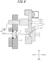
- FIG. 8 schematically illustrates a portion of the components of FIG. 7 .
- the gas analyzer 1 includes an alignment unit 24 inside the analysis unit 20.
- the alignment unit 24 adjusts the beam diameter W of the measurement light at the incident end face of the reflector 15 in the probe 10.
- the optical emitter 21 disposed inside the analysis unit 20 includes a piezoelectric element 21a.
- the piezoelectric element 21a imparts vibration with a phase differing by 180°, for example, to control optical noise occurring between the light source and an optical lens 24a.
- the optical emitter 21 includes a laser arm 21b that contacts one surface of the piezoelectric element 21a.
- the optical emitter 21 includes a laser holder 21c attached to the laser arm 21b.
- the optical emitter 21 includes a light-emitting element 21d supported by the tip of the laser holder 21c.
- the light-emitting element 21d includes a semiconductor laser element, for example.
- the optical emitter 21 includes a plunger 21e that pushes the laser arm 21b to the left.
- the alignment unit 24 includes an optical lens 24a, disposed between the optical emitter 21 and the probe 10, that acts on the measurement light.
- the optical lens 24a is configured to condense the measurement light.
- the optical lens 24a is, for example, a plano-convex lens.
- the optical lens 24a is fixed by a fixing unit 25 so that the flat surface of the plano-convex lens faces the optical emitter 21 and the convex surface faces the probe 10.
- the optical lens 24a is made of a material exhibiting good wavelength properties with respect to the wavelength of the measurement light from the optical emitter 21.
- the optical lens 24a is made of material with a transmittance of substantially 100% relative to the wavelength of the measurement light.
- the optical lens 24a has a focal length such that the beam diameter W of the measurement light at the incident end face of the reflector 15 in the probe 10 is adjusted roughly to a desired value.
- the alignment unit 24 further includes an alignment mechanism 24b that changes the distance between the optical lens 24a and the optical emitter 21 along the optical axis A of the measurement light.
- the alignment mechanism 24b includes an alignment screw 24c rotatably supported about an axis substantially parallel to the optical axis A by the fixing unit 25 that fixes the optical lens 24a.
- the alignment screw 24c includes a narrow-pitch screw capable of minute alignments to the distance between the optical lens 24a and the optical emitter 21.
- the alignment screw 24c includes a screw formed to have a 0.2 mm pitch. One end of the alignment screw 24c is in contact with the piezoelectric element 21a of the optical emitter 21, and the other end is exposed from the fixing unit 25 at the opposite side from the optical emitter 21.
- the alignment unit 24 is capable of minute alignments to the beam diameter W by changing the distance between the light-emitting element 21d and the optical lens 24a inside the optical emitter 21.
- the laser arm 21b and the laser holder 21c move along the optical axis A via the piezoelectric element 21a by the alignment screw 24c rotating about an axis substantially parallel to the optical axis A. Consequently, the light-emitting element 21d also moves along the optical axis A.
- the optical lens 24a is fixed by the fixing unit 25, so that the position of the optical lens 24a along the optical axis A does not change.
- the origin of the measurement light is adjusted by the optical lens 24a being fixed and the light-emitting element 21d being moved.
- the accuracy of alignment of the beam diameter W therefore improves, making alignment easy.
- the alignment screw 24c pushes the piezoelectric element 21a to the right when tightened. At this time, the light-emitting element 21d moves away from the optical lens 24a, and the distance between the light-emitting element 21d and the optical lens 24a increases. The beam diameter W decreases in this case.
- the alignment screw 24c is loosened, the flange 21e pushes the laser arm 21b to the left. At this time, the light-emitting element 21d moves closer to the optical lens 24a, and the distance between the light-emitting element 21d and the optical lens 24a decreases. The beam diameter W increases in this case.
- the alignment unit 24 expands the beam diameter W of the measurement light at the reflector 15. Specifically, the alignment unit 24 expands the beam diameter W of the measurement light to be greater at the reflector 15 than the beam diameter when the measurement light is parallel light. For example, the alignment unit 24 expands the beam diameter W of the measurement light so that the measurement light is included at both of the ends of the reflector 15 in a direction substantially perpendicular to the optical axis A. In other words, the alignment unit 24 expands the beam diameter W of the measurement light to be greater than the width of the reflector 15 in a direction substantially perpendicular to the optical axis A.
- the alignment unit 24 expands the beam diameter W of the measurement light so that the measurement light includes the positions of the reflector 15 at both ends of the vibration of the tip of the probe 10 in a direction substantially perpendicular to the optical axis A of the measurement light.
- directions substantially perpendicular to the optical axis A include the up-down direction, a direction approximating the up-down direction, the front-back direction, and a direction approximating the front-back direction.
- the optical axis A of the measurement light is, for example, substantially parallel to the left-right direction.
- the tip of the probe 10 moves in the up-down direction, for example.
- the alignment unit 24 increases the beam diameter W of the measurement light at the incident end face of the reflector 15 in the probe 10 so that the measurement light includes the positions of the reflector 15 at the upper and lower ends of vibration of the tip of the probe 10.
- the alignment unit 24 adjusts the beam diameter W so that when the probe 10 is not vibrating, for example, the measurement light is sufficiently wider than when the measurement light is parallel light.
- the alignment unit 24 adjusts the beam diameter W of the measurement light to expand from a beam diameter ⁇ of approximately 3 mm to 4 mm for parallel light to a beam diameter ⁇ of approximately 20 mm to 120 mm at a position 4 m away.
- the 4 m position prescribed here corresponds, for example, to the optical path length of measurement light that is emitted from the optical emitter 21 and returns to the optical receiver 22 when the external length from the outer surface of the flange 11 to the tip of the probe 10 is 2 m.
- the distance between the light-emitting element 21d and the optical lens 24a needs to be decreased to increase the beam diameter W of the measurement light at the incident end face of the reflector 15 in the probe 10.
- An example method of adjusting the beam diameter W of the measurement light is described below.
- the value of the beam diameter W after the measurement light is enlarged is determined in advance by any appropriate method, including calculation and experimentation, on the basis of the length of the probe 10 and the amount of measurement light that the optical receiver 22 needs to receive for analysis.
- the alignment width over which the position of the light-emitting element 21d can be adjusted along the optical axis A relative to the fixed position of the optical lens 24a at the time of manufacturing the gas analyzer 1, for example, is determined.
- an optical lens 24a that allows the light-emitting element 21d to be adjusted within the aforementioned alignment width to the optimal position and that yields a beam diameter W approximating the value of the beam diameter W determined in the first step is selected.
- the alignment screw 24c is minutely adjusted so that the actual beam diameter W matches the value of the beam diameter W determined in the first step. The distance between the selected optical lens 24a and the light-emitting element 21d is thus determined.
- the alignment screw 24c is, in principle, fixed after thus being adjusted once during initial settings in the manufacturing process of the gas analyzer 1.
- the gas analyzer 1 can ensure receipt by the optical receiver 22 of the necessary amount of measurement light for concentration analysis, even in a vibrating environment.
- the expansion of the measurement light causes the measurement light irradiated by the optical emitter 21 to be incident on the reflector 15 across the vibration range.
- the alignment unit 24 specifically expands the beam diameter W of the measurement light to be greater than the width of the reflector 15, so that even if the position of the reflector 15 at the resonance point is shifted in the up-down or front-back directions, a portion of the measurement light is incident on the reflector 15. Consequently, the optical receiver 22 can stably receive the measurement light reflected by the reflector 15.
- the gas analyzer 1 is configured for the beam diameter W of the measurement light to be narrower than the width of the reflector 15, so that substantially all of the measurement light is reflected by the reflector 15.
- the amount of measurement light received by the optical receiver 22 decreases as the beam diameter W of the measurement light is expanded. Even if only a portion of the measurement light returns, however, the measurement signal can be amplified by an amplifier circuit to allow analysis of the component concentration of the measurement target component. Accordingly, when the tip of the probe 10 is vibrating, the variation in the gas concentration reading of the gas analyzer 1 is significantly reduced as compared to when the measurement light is parallel light. Increasing the beam diameter W of the measurement light thus improves the measurement tolerance with respect to displacement of the tip of the probe 10.
- the alignment unit 24 includes the optical lens 24a that condenses the measurement light, the beam diameter W of the measurement light can be roughly adjusted towards a desired value. Variation in the gas concentration reading of the gas analyzer 1 is therefore significantly reduced. Accordingly, the measurement tolerance with respect to displacement of the tip of the probe 10 is improved.
- the alignment unit 24 further includes the alignment mechanism 24b that changes the distance between the optical lens 24a and the optical emitter 21 along the optical axis A of the measurement light, the beam diameter W of the measurement light can be minutely adjusted towards a desired value. Variation in the gas concentration reading of the gas analyzer 1 is therefore further reduced. Accordingly, the measurement tolerance with respect to displacement of the tip of the probe 10 is further improved.
- the shape, arrangement, orientation, number, and the like of the above-described components are not limited to the above explanation or the drawings.
- the shape, arrangement, orientation, number, and the like of each component may be selected freely as long as the functions of the component can be achieved.
- the gas analyzer 1 may include any component other than the above-described components.
- the gas analyzer 1 may further include a beam splitter that splits off a portion of the measurement light as reference light immediately after emission by the optical emitter 21.
- the gas analyzer 1 may further include a reference cell that has therein a gas identical to the measurement target component in the gas to be measured G.
- the reference cell includes a photodetector that receives the reference light after the reference light passes through a region in which the gas is included. The photodetector outputs a TDLAS signal with respect to the gas, contained at a known concentration, that is identical to the measurement target component.
- the gas analyzer 1 When including such a reference cell, the gas analyzer 1 according to the above-described embodiment can also stabilize the amount of reference light received at the photodetector inside the reference cell.
- the amount of reference light received at the photodetector is stable even if the position of the photodetector varies due to vibration of the gas analyzer 1, for example, since the increase in beam diameter of the measurement light due to the alignment unit 24 also increases the beam diameter of the reference light.
- the optical lens 24a is not limited to being a plano-convex lens.
- the optical lens 24a may be any lens capable of increasing the beam diameter W of the measurement light at the incident end face of the reflector 15 in the probe 10.
- the optical lens 24a may be a biconvex lens or a concave lens.
- the optical lens 24a may be an aspheric lens.
- the alignment mechanism 24b has been described as changing the distance between the optical lens 24a and the optical emitter 21 along the optical axis A of the measurement light by the light-emitting element 21d moving with respect to the optical lens 24a.
- the alignment method is not, however, limited to this example.
- the distance between the optical lens 24a and the light-emitting element 21d may be adjusted by movement of at least one of these components.
- the alignment unit 24 may be configured to include a plurality of optical lenses 24a, with different focal lengths, and to be capable of switching the optical lens 24a with any appropriate switching mechanism in order to roughly adjust the beam diameter W.
- Both the emitted light L1 and the reflected light L2 have been described as passing through the measurement region R1, but this example is not limiting.
- the gas analyzer 1 is capable of analyzing the component concentration of the measurement target component in the gas to be measured G included in the measurement region R1, it suffices if only one of the emitted light L1 and the reflected light L2 passes through the measurement region R1.
- the gas analyzer 1 has been described as being a probe-type device but is not limited to this type.
- the gas analyzer 1 may, for example, be configured so that the analysis unit 20 and the reflector 15 are separate bodies facing each other across the flue P.
- any appropriate reflecting structure constituting the reflector 15 may be attached to the opposite side from the side of the flue wall S to which the analysis unit 20 is attached.
- the reflecting structure constituting the reflector 15 may, for example, be attached to the inner surface or the outer surface of the flue wall S.
- the gas concentration reading may vary greatly over time due to vibration if the measurement light irradiated from the optical emitter 21 is parallel light. Vibration of the flue wall S may, for example, cause at least one of the relative positions of the reflector 15 and the optical emitter 21 and the relative positions of the reflector 15 and the optical receiver 22 to change, significantly reducing the optical intensity of the measurement light that returns to the optical receiver 22. Consequently, it becomes difficult to acquire a scan signal having the strength necessary for analysis.
- the gas analyzer 1 can ensure receipt by the optical receiver 22 of the necessary amount of measurement light for concentration analysis even in this case, just as when the gas analyzer 1 is a probe-type device. Specifically, even if the relative positions of the reflector 15 and the optical emitter 21 change, the expansion of the measurement light causes the measurement light irradiated by the optical emitter 21 to be incident on the reflector 15. Moreover, even if the relative positions of the reflector 15 and the optical receiver 22 change, the measurement light reflected by the reflector 15 is incident on the optical receiver 22. The optical receiver 22 can thus stably receive the measurement light reflected by the reflector 15.
Landscapes
- Physics & Mathematics (AREA)
- Spectroscopy & Molecular Physics (AREA)
- General Physics & Mathematics (AREA)
- Health & Medical Sciences (AREA)
- Life Sciences & Earth Sciences (AREA)
- Chemical & Material Sciences (AREA)
- Analytical Chemistry (AREA)
- Biochemistry (AREA)
- General Health & Medical Sciences (AREA)
- Immunology (AREA)
- Pathology (AREA)
- Optics & Photonics (AREA)
- Investigating Or Analysing Materials By Optical Means (AREA)
Abstract
Description
- The present application claims priority to and the benefit of Japanese Patent Application No.
2018-078486 filed April 16, 2018 - The present disclosure relates to a gas analyzer.
- An apparatus for optically calculating the concentration of a gas to be measured flowing through a predetermined flow path is known, such as the gas concentration measurement apparatus disclosed in patent literature (PTL) 1.
- PTL 1:
JP2010185694A - The gas concentration measurement apparatus disclosed in
PTL 1 includes a reflecting mirror at the tip of a probe extending through the gas to be measured. The reflecting mirror reflects measurement light towards an optical receiver. In this case, if the probe vibrates and the position of the probe tip changes, for example, the amount of measurement light reflected by the reflecting mirror decreases depending on the position, and the amount of light received at the optical receiver decreases. - It is an objective of the present disclosure to provide a gas analyzer that can ensure receipt at the optical receiver of the necessary amount of measurement light for concentration analysis, even in a vibrating environment.
- A gas analyzer according to an embodiment includes an optical emitter configured to irradiate measurement light into a measurement region including a gas to be measured, a reflector configured to reflect the measurement light irradiated from the optical emitter, an optical receiver configured to receive the measurement light reflected by the reflector, and an alignment unit configured to expand a beam diameter of the measurement light at the reflector. This configuration can ensure receipt at the optical receiver of the necessary amount of measurement light for concentration analysis, even in a vibrating environment. Specifically, even when a probe including the reflector vibrates at the resonance point, the expansion of the measurement light causes the measurement light irradiated by the optical emitter to be incident on the reflector across the vibration range.
- In a gas analyzer according to an embodiment, the alignment unit may be configured to expand the beam diameter of the measurement light to be greater than the width of the reflector in a direction substantially orthogonal to the optical axis of the measurement light. This configuration causes a portion of the measurement light to be incident on the reflector even if the position of the reflector at the resonance point is shifted in the up-down or front-back directions. The optical receiver can thus stably receive the measurement light reflected by the reflector.
- In a gas analyzer according to an embodiment, the alignment unit may include an optical lens disposed between the optical emitter and the measurement region and configured to condense the measurement light. With this configuration, the beam diameter of the measurement light can be roughly adjusted towards a desired value. Variation in the gas concentration reading of the gas analyzer is therefore significantly reduced. Accordingly, the measurement tolerance with respect to displacement of the tip of the probe is improved.
- In a gas analyzer according to an embodiment, the optical lens may be a plano-convex lens, a flat surface of the plano-convex lens may face the optical emitter, and a convex surface of the plano-convex lens may face the measurement region.
- In a gas analyzer according to an embodiment, the alignment unit may further include an alignment mechanism configured to change the distance between the optical lens and the optical emitter along the optical axis of the measurement light. With this configuration, the beam diameter of the measurement light can be minutely adjusted towards a desired value. Variation in the gas concentration reading of the gas analyzer is therefore further reduced. Accordingly, the measurement tolerance with respect to displacement of the tip of the probe is further improved.
- In a gas analyzer according to an embodiment, the alignment mechanism may include an alignment screw rotatably supported about an axis substantially parallel to the optical axis by a fixing unit configured to fix the optical lens, one end of the alignment screw may be in contact with the optical emitter, and another end of the alignment screw may be exposed from the fixing unit at an opposite side from the optical emitter.
- A gas analyzer according to an embodiment may further include a probe extending along an optical axis of the measurement light so as to overlap the measurement region, and the reflector may be positioned at the opposite tip of the probe from the optical emitter. The gas analyzer can, for example, thereby be configured as a probe-type gas analyzer in which a light source, a reflecting structure, and a photodetector are integrally built into the gas analyzer.
- The present disclosure can provide a gas analyzer that can ensure receipt at the optical receiver of the necessary amount of measurement light for concentration analysis, even in a vibrating environment.
- In the accompanying drawings:
-
FIG. 1 is a perspective view from above illustrating a gas analyzer according to an embodiment; -
FIG. 2 is a perspective view from below illustrating the gas analyzer ofFIG. 1 ; -
FIG. 3 is a schematic cross-section along the I-I arrows inFIG. 1 ; -
FIG. 4 is a schematic diagram that corresponds toFIG. 3 and illustrates the behavior of the probe in a vibrating environment; -
FIG. 5 is a schematic diagram illustrating a scan signal outputted by an optical receiver; -
FIG. 6 is a schematic diagram that corresponds toFIG. 3 and illustrates measurement light irradiated from an optical emitter; -
FIG. 7 is an enlarged cross-section illustrating an enlargement of the II portion in a cross-section along the I-I arrows inFIG. 1 ; and -
FIG. 8 schematically illustrates a portion of the components ofFIG. 7 . - Embodiments of the present disclosure are described below with reference to the drawings. The front-back, left-right, and up-down directions referred to below are based on the directions of the arrows in the drawings. The directions of the arrows are consistent in
FIG. 1 through FIG. 4 and inFIG. 6 through FIG. 8 . - An example in which a gas to be measured G flows upward from below in each drawing is described below. The flow direction of the gas to be measured G is not limited to this case. The gas to be measured G may flow in any direction, and a
gas analyzer 1 according to an embodiment may be arranged in any direction in accordance with the flow direction of the gas to be measured G. -
FIG. 1 is a perspective view from above illustrating thegas analyzer 1 according to an embodiment.FIG. 2 is a perspective view from below illustrating thegas analyzer 1 ofFIG. 1 .FIG. 3 is a schematic cross-section along the I-I arrows inFIG. 1 . As an example,FIG. 3 illustrates thegas analyzer 1 ofFIG. 1 attached to a flue wall S to analyze the component concentration of a certain component included in the gas to be measured G that flows in a flue P. For the sake of explanation, the configuration of thegas analyzer 1 according to an embodiment is simplified inFIG. 3 . Specifically, details of the internal configuration of theanalysis unit 20, such as analignment unit 24, afixing unit 25, and a more detailed configuration of anoptical emitter 21, described below, are omitted inFIG. 3 . - The functions and configuration of the
gas analyzer 1 according to an embodiment are mainly described with reference toFIGS. 1 to 3 . - The
gas analyzer 1 is, for example, attached directly to the flow path through which the gas to be measured G flows. Thegas analyzer 1 analyzes the component concentration of a measurement target component. The gas to be measured G may, for example, include a gas such as CO, CO2, H2O, CnHm (a hydrocarbon), NH3, or O2. The flow path includes piping, a flue, a combustion furnace, and the like. - The
gas analyzer 1 includes a probe-type tunable diode laser absorption spectroscopy (TDLAS) gas analyzer, for example, that has an explosion-proof structure and is used in an explosion-proof area. Probe-type refers, for example, to how thegas analyzer 1 has a light source, a reflecting structure, and a photodetector integrally built therein and is structured for insertion from one end into the flow path through which the gas to be measured G flows. Thegas analyzer 1 analyzes the component concentration of the measurement target component by irradiating a laser beam that becomes measurement light onto the gas to be measured G, which includes a process gas or the like, for example. - The gas molecules included in the gas to be measured G exhibit a light absorption spectrum based on the vibration and rotational energy transition of the molecules in a region from infrared to near infrared. The absorption spectrum is unique to the component molecules. By the Lambert-Beer law, the absorbance of gas molecules with regard to the measurement light is proportional to their component concentration and the optical path length. Accordingly, the component concentration of the measurement target component can be analyzed by measuring the absorption spectrum intensity.
- In TDLAS, a semiconductor laser beam with a sufficiently narrower line width than the absorption line width of the energy transition of the gas molecules is irradiated onto the gas to be measured G as measurement light. The wavelength of measurement light is swept by high-speed modulation of the drive current for the semiconductor laser. The optical intensity of the measurement light that passes through the gas to be measured G is measured to acquire one independent absorption spectrum.
- The sweep range of the laser beam differs depending on use. When the measurement target component is O2, the line width of the laser light is, for example, 0.0002 nm, and the sweep width is, for example, 0.1 nm to 0.2 nm. The absorption spectrum is measured by sweeping over a sweep width of 0.1 nm to 0.2 nm. The component concentration of the measurement target component is calculated by performing concentration conversion on the acquired single absorption spectrum. Methods of concentration conversion include known methods, such as the peak height method, the spectral area method, and the 2f method.
- The major components of the
gas analyzer 1 are aprobe 10 and ananalysis unit 20. As illustrated in theexample gas analyzer 1 ofFIG. 3 , the majority of theprobe 10 extends inside the flue P, and theanalysis unit 20 is supported while disposed on the outside of the flue P. Specifically, thegas analyzer 1 is supported by the flue wall S when aflange 11, formed on a portion of theprobe 10, is attached to the flue wall S from the outside. - As illustrated in
FIG. 1 andFIG. 2 , theprobe 10 is a cylindrical body with a substantially circular cross-sectional shape, for example. The external length from the outer surface of theflange 11 to the tip of theprobe 10 is, for example, approximately 0.5 m to 2 m. Theprobe 10 is formed by any metal member. As illustrated inFIG. 3 , theprobe 10 extends in a substantially orthogonal direction to the flow direction of the gas to be measured G inside the flue P, for example. - The
probe 10 extends in the left-right direction and includes anopening 12 that opens upward, as illustrated inFIG. 1 . Theopening 12 exposes the corresponding interior section of theprobe 10 inside the flue P. Theprobe 10 includes a plurality ofribs 13 provided in theopening 12 to maintain the strength of theprobe 10. As illustrated inFIG. 2 , theprobe 10 includesnotches 14 formed by cutting out a portion of the surface of theprobe 10 from below, towards the inside. Thenotches 14 are respectively formed at substantially the same left-right positions as the left-right ends of theopening 12. Thenotches 14 connect the inner section of theprobe 10 exposed in the flue P by theopening 12 with the space in the flue P below the inner section. - As illustrated in
FIG. 3 , theprobe 10 includes areflector 15 in the inner section at the tip inside the flue P. Thereflector 15 includes any reflecting structure for reflecting the measurement light, such as a corner cube prism or a retroreflector. - The
analysis unit 20 is attached at the opposite end from the tip of theprobe 10 where thereflector 15 is attached. Theanalysis unit 20 is located outside of the flue P. Theanalysis unit 20 includes theoptical emitter 21 for irradiating the measurement light onto the gas to be measured G and anoptical receiver 22 for receiving the measurement light reflected by thereflector 15. Theanalysis unit 20 further includes acalculation unit 23. Theoptical emitter 21, theoptical receiver 22, and thecalculation unit 23 are electrically connected via a plurality of electronic substrates. The housing of theanalysis unit 20 is, for example, an explosion-proof container that stores each of these components. Theanalysis unit 20 has a module structure for integrally storing these components. Theoptical emitter 21 and theoptical receiver 22 are arranged near each other inside theanalysis unit 20. - The
optical emitter 21 includes any light source capable of measurement by TDLAS with respect to the gas to be measured G. For example, theoptical emitter 21 includes a semiconductor laser. Theoptical receiver 22 includes any photodetector capable of measurement by TDLAS with respect to the gas to be measured G. For example, theoptical receiver 22 includes a photodiode. Thecalculation unit 23 includes one or more processors. Thecalculation unit 23 controls overall operations of thegas analyzer 1, including theoptical emitter 21 and theoptical receiver 22. - A portion of the gas to be measured G flowing upward from below in the flue P flows into a measurement region R1 inside the
probe 10 from below through thenotches 14. Another portion of the gas to be measured G wraps around and flows into the measurement region R1 inside theprobe 10 through the opening 12 from above. In this way, the gas to be measured G flowing through the flue P flows inside theprobe 10. The gas to be measured G flowing inside theprobe 10 flows out into the flue P once again through theopening 12, for example. Here, the measurement region R1 includes an interior space of theprobe 10 exposed to the flue P by theopening 12. In this way, the measurement region R1 is filled with the gas to be measured G. - On the other hand, a purge gas is supplied by any appropriate mechanism to regions R2 and R3 formed on the left and right sides of the measurement region R1 inside the
probe 10. InFIG. 3 , the boundary between the measurement region R1 and the region R2 and the boundary between the measurement region R1 and the region R3 are indicated by dotted lines. The purge gas suppresses contact between the gas to be measured G and optical components such as thereflector 15, theoptical emitter 21, and theoptical receiver 22 to prevent problems, such as contamination or corrosion, of these optical components. The regions R2 and R3 are thus filled with the purge gas. - The
notches 14 suppress mixing of the gas to be measured G and the purge gas between the measurement region R1 and the regions R2 and R3. Specifically, thenotches 14 guide the gas to be measured G from the flue P into the measurement region R1 in theprobe 10, thereby suppressing mixing of the purge gas into the measurement region R1. Similarly, thenotches 14 suppress mixing of the gas to be measured G into the regions R2 and R3. - The
optical emitter 21 irradiates measurement light towards thereflector 15 of theprobe 10. InFIG. 3 , the measurement light before being reflected by thereflector 15 is indicated as emitted light L1. Theoptical emitter 21 irradiates the emitted light L1 into the measurement region R1 that includes the gas to be measured G. The emitted light L1 propagates inside theprobe 10, which extends along the optical axis of the emitted light L1 so as to overlap the measurement region R1. The emitted light L1 is then incident on thereflector 15. Thereflector 15 is positioned at the opposite tip of theprobe 10 from theoptical emitter 21 and reflects a portion of the emitted light L1 that passed through the measurement region R1. InFIG. 3 , the measurement light after being reflected by thereflector 15 is indicated as reflected light L2. The reflected light L2 again passes through the inside of theprobe 10 that includes the measurement region R1. Theoptical receiver 22 receives the reflected light L2 that was reflected by thereflector 15 and passed through the measurement region R1. In this manner, the measurement region R1 is arranged between theoptical emitter 21 and theoptical receiver 22 in the optical path of the emitted light L1 and the reflected light L2. - The
optical receiver 22 electrically amplifies a measurement signal related to the detected measurement light using any appropriate amplifier circuit and outputs the detected optical intensity of the measurement light to thecalculation unit 23 as a scan signal. A portion of each of the emitted light L1 and the reflected light L2 is absorbed, when passing through the inside of theprobe 10, by the gas to be measured G flowing in the measurement region R1. The component concentration of the measurement target component in the gas to be measured G is calculated by measuring the absorption spectrum on the basis of the measurement signal acquired by theoptical receiver 22. - In the above-described probe-
type gas analyzer 1, each of theoptical emitter 21, thereflector 15, and theoptical receiver 22 need to satisfy predetermined conditions in a state of attachment at the installation site. The predetermined conditions include positional relationships between these optical components such that the emitted light L1 irradiated from theoptical emitter 21 passes through the measurement region R1 and is reflected by thereflector 15, and the reflected light L2 passes back through the measurement region R1 and is incident on theoptical receiver 22. -
FIG. 4 is a schematic diagram that corresponds toFIG. 3 and illustrates the behavior of theprobe 10 in a vibrating environment.FIG. 5 is a schematic diagram illustrating a scan signal outputted by theoptical receiver 22. With reference toFIGS. 4 and5 , an example in which thegas analyzer 1 is installed on the flue wall S in a vibrating environment is considered. - Steady vibrations or vibrations due to temporary disturbances may occur, depending on the environment in which the probe-
type gas analyzer 1 is installed. Thegas analyzer 1 is affected by the vibrations in this case. For example, the flue wall S to which thegas analyzer 1 is attached may vibrate under the influence of another device that includes a motor, a fan, and the like near the flue P. In the case of ordinary vibrations, thegas analyzer 1 simply vibrates together with the flue wall S, and measurement is hardly affected. When the frequency of vibration of the flue wall S substantially matches the natural frequency (resonance point) fn of thegas analyzer 1, however, theprobe 10 resonates with the flue wall S as a fixed end and ends up vibrating violently, as indicated by the dashed double-dotted lines inFIG. 4 . Here, stating that "the frequency of vibration of the flue wall S substantially matches the natural frequency fn of thegas analyzer 1" includes, for example, the cases of the frequencies being identical or being within a range of ±0.1 Hz of each other. - The amplitude of the tip of the
probe 10 is approximately 100 mm, for example, when the length of the probe 10 (specifically, the external length from the outer surface of theflange 11 to the tip of the probe 10) is 2 m, and the acceleration during vibration is 1.4 m/s2. Accordingly, when the measurement light irradiated from theoptical emitter 21 is parallel light with a beam diameter φ of approximately 3 mm to 4 mm, the majority of the measurement light is no longer incident on thereflector 15, depending on the position of thereflector 15. The optical intensity of the measurement light that returns to theoptical receiver 22 is thereby greatly reduced. Consequently, it becomes difficult to acquire a scan signal having the strength necessary for analysis. Moreover, the amount of light received at theoptical receiver 22 decreases. As illustrated inFIG. 5 , the proportion of noise relative to the scan signal is therefore increased, and along with the scan signal, the noise also ends up being amplified by the amplifier circuit. In this way, the proportion of noise included in the scan signal increases due to vibration of theprobe 10 depending on the position of thereflector 15. This makes the gas concentration reading of thegas analyzer 1 vary greatly over time and makes stable analysis difficult. - The
gas analyzer 1 according to an embodiment is configured so that even when theprobe 10 vibrates as described above, and the frequency of the vibration substantially matches the resonance point, for example, the measurement light irradiated by theoptical emitter 21 is reflected by thereflector 15 and returns to theoptical receiver 22 with sufficient optical intensity across the vibration range. As a result, thegas analyzer 1 achieves a stable gas concentration reading with respect to the component concentration of the measurement target component in the gas to be measured G. -
FIG. 6 is a schematic diagram that corresponds toFIG. 3 and illustrates measurement light irradiated from theoptical emitter 21.FIG. 7 is an enlarged cross-section illustrating an enlargement of the II portion in a cross-section along the I-I arrows inFIG. 1 .FIG. 8 schematically illustrates a portion of the components ofFIG. 7 . As illustrated inFIGS. 7 and8 , thegas analyzer 1 includes analignment unit 24 inside theanalysis unit 20. Thealignment unit 24 adjusts the beam diameter W of the measurement light at the incident end face of thereflector 15 in theprobe 10. With reference toFIG. 6 through FIG. 8 , the configuration of theoptical emitter 21 is described in detail, and the configuration and function of thealignment unit 24 in thegas analyzer 1 according to an embodiment for achieving stable gas concentration readings are described below. - As illustrated in
FIG. 7 andFIG. 8 , theoptical emitter 21 disposed inside theanalysis unit 20 includes apiezoelectric element 21a. Thepiezoelectric element 21a imparts vibration with a phase differing by 180°, for example, to control optical noise occurring between the light source and anoptical lens 24a. Theoptical emitter 21 includes alaser arm 21b that contacts one surface of thepiezoelectric element 21a. Theoptical emitter 21 includes alaser holder 21c attached to thelaser arm 21b. Theoptical emitter 21 includes a light-emittingelement 21d supported by the tip of thelaser holder 21c. The light-emittingelement 21d includes a semiconductor laser element, for example. Theoptical emitter 21 includes aplunger 21e that pushes thelaser arm 21b to the left. - The
alignment unit 24 includes anoptical lens 24a, disposed between theoptical emitter 21 and theprobe 10, that acts on the measurement light. Theoptical lens 24a is configured to condense the measurement light. Theoptical lens 24a is, for example, a plano-convex lens. Theoptical lens 24a is fixed by a fixingunit 25 so that the flat surface of the plano-convex lens faces theoptical emitter 21 and the convex surface faces theprobe 10. Theoptical lens 24a is made of a material exhibiting good wavelength properties with respect to the wavelength of the measurement light from theoptical emitter 21. For example, theoptical lens 24a is made of material with a transmittance of substantially 100% relative to the wavelength of the measurement light. Theoptical lens 24a has a focal length such that the beam diameter W of the measurement light at the incident end face of thereflector 15 in theprobe 10 is adjusted roughly to a desired value. - The
alignment unit 24 further includes analignment mechanism 24b that changes the distance between theoptical lens 24a and theoptical emitter 21 along the optical axis A of the measurement light. In greater detail, thealignment mechanism 24b includes analignment screw 24c rotatably supported about an axis substantially parallel to the optical axis A by the fixingunit 25 that fixes theoptical lens 24a. Thealignment screw 24c includes a narrow-pitch screw capable of minute alignments to the distance between theoptical lens 24a and theoptical emitter 21. For example, thealignment screw 24c includes a screw formed to have a 0.2 mm pitch. One end of thealignment screw 24c is in contact with thepiezoelectric element 21a of theoptical emitter 21, and the other end is exposed from the fixingunit 25 at the opposite side from theoptical emitter 21. - In addition to making a rough alignment to the beam diameter W with the
optical lens 24a, thealignment unit 24 is capable of minute alignments to the beam diameter W by changing the distance between the light-emittingelement 21d and theoptical lens 24a inside theoptical emitter 21. For example, thelaser arm 21b and thelaser holder 21c move along the optical axis A via thepiezoelectric element 21a by thealignment screw 24c rotating about an axis substantially parallel to the optical axis A. Consequently, the light-emittingelement 21d also moves along the optical axis A. Theoptical lens 24a, on the other hand, is fixed by the fixingunit 25, so that the position of theoptical lens 24a along the optical axis A does not change. The origin of the measurement light is adjusted by theoptical lens 24a being fixed and the light-emittingelement 21d being moved. The accuracy of alignment of the beam diameter W therefore improves, making alignment easy. - In greater detail, the
alignment screw 24c pushes thepiezoelectric element 21a to the right when tightened. At this time, the light-emittingelement 21d moves away from theoptical lens 24a, and the distance between the light-emittingelement 21d and theoptical lens 24a increases. The beam diameter W decreases in this case. When thealignment screw 24c is loosened, theflange 21e pushes thelaser arm 21b to the left. At this time, the light-emittingelement 21d moves closer to theoptical lens 24a, and the distance between the light-emittingelement 21d and theoptical lens 24a decreases. The beam diameter W increases in this case. - The
alignment unit 24 expands the beam diameter W of the measurement light at thereflector 15. Specifically, thealignment unit 24 expands the beam diameter W of the measurement light to be greater at thereflector 15 than the beam diameter when the measurement light is parallel light. For example, thealignment unit 24 expands the beam diameter W of the measurement light so that the measurement light is included at both of the ends of thereflector 15 in a direction substantially perpendicular to the optical axis A. In other words, thealignment unit 24 expands the beam diameter W of the measurement light to be greater than the width of thereflector 15 in a direction substantially perpendicular to the optical axis A. For example, thealignment unit 24 expands the beam diameter W of the measurement light so that the measurement light includes the positions of thereflector 15 at both ends of the vibration of the tip of theprobe 10 in a direction substantially perpendicular to the optical axis A of the measurement light. - Here, directions substantially perpendicular to the optical axis A include the up-down direction, a direction approximating the up-down direction, the front-back direction, and a direction approximating the front-back direction. As illustrated in
FIG. 6 , the optical axis A of the measurement light is, for example, substantially parallel to the left-right direction. The tip of theprobe 10 moves in the up-down direction, for example. Thealignment unit 24 increases the beam diameter W of the measurement light at the incident end face of thereflector 15 in theprobe 10 so that the measurement light includes the positions of thereflector 15 at the upper and lower ends of vibration of the tip of theprobe 10. In greater detail, thealignment unit 24 adjusts the beam diameter W so that when theprobe 10 is not vibrating, for example, the measurement light is sufficiently wider than when the measurement light is parallel light. When the external length from the outer surface of theflange 11 to the tip of theprobe 10 is 2 m, for example, thealignment unit 24 adjusts the beam diameter W of the measurement light to expand from a beam diameter φ of approximately 3 mm to 4 mm for parallel light to a beam diameter φ of approximately 20 mm to 120 mm at a position 4 m away. The 4 m position prescribed here corresponds, for example, to the optical path length of measurement light that is emitted from theoptical emitter 21 and returns to theoptical receiver 22 when the external length from the outer surface of theflange 11 to the tip of theprobe 10 is 2 m. - The distance between the light-emitting
element 21d and theoptical lens 24a needs to be decreased to increase the beam diameter W of the measurement light at the incident end face of thereflector 15 in theprobe 10. An example method of adjusting the beam diameter W of the measurement light is described below. - In the first step, the value of the beam diameter W after the measurement light is enlarged is determined in advance by any appropriate method, including calculation and experimentation, on the basis of the length of the
probe 10 and the amount of measurement light that theoptical receiver 22 needs to receive for analysis. - In the second step, the alignment width over which the position of the light-emitting
element 21d can be adjusted along the optical axis A relative to the fixed position of theoptical lens 24a at the time of manufacturing thegas analyzer 1, for example, is determined. - In the third step, an
optical lens 24a that allows the light-emittingelement 21d to be adjusted within the aforementioned alignment width to the optimal position and that yields a beam diameter W approximating the value of the beam diameter W determined in the first step is selected. - In the fourth step, the
alignment screw 24c is minutely adjusted so that the actual beam diameter W matches the value of the beam diameter W determined in the first step. The distance between the selectedoptical lens 24a and the light-emittingelement 21d is thus determined. - The
alignment screw 24c is, in principle, fixed after thus being adjusted once during initial settings in the manufacturing process of thegas analyzer 1. - The
gas analyzer 1 according to the above embodiment can ensure receipt by theoptical receiver 22 of the necessary amount of measurement light for concentration analysis, even in a vibrating environment. In greater detail, even when theprobe 10 vibrates at the resonance point, the expansion of the measurement light causes the measurement light irradiated by theoptical emitter 21 to be incident on thereflector 15 across the vibration range. Thealignment unit 24 specifically expands the beam diameter W of the measurement light to be greater than the width of thereflector 15, so that even if the position of thereflector 15 at the resonance point is shifted in the up-down or front-back directions, a portion of the measurement light is incident on thereflector 15. Consequently, theoptical receiver 22 can stably receive the measurement light reflected by thereflector 15. - Normally, to increase the amount of measurement light received by the
optical receiver 22, thegas analyzer 1 is configured for the beam diameter W of the measurement light to be narrower than the width of thereflector 15, so that substantially all of the measurement light is reflected by thereflector 15. The amount of measurement light received by theoptical receiver 22 decreases as the beam diameter W of the measurement light is expanded. Even if only a portion of the measurement light returns, however, the measurement signal can be amplified by an amplifier circuit to allow analysis of the component concentration of the measurement target component. Accordingly, when the tip of theprobe 10 is vibrating, the variation in the gas concentration reading of thegas analyzer 1 is significantly reduced as compared to when the measurement light is parallel light. Increasing the beam diameter W of the measurement light thus improves the measurement tolerance with respect to displacement of the tip of theprobe 10. - Since the
alignment unit 24 includes theoptical lens 24a that condenses the measurement light, the beam diameter W of the measurement light can be roughly adjusted towards a desired value. Variation in the gas concentration reading of thegas analyzer 1 is therefore significantly reduced. Accordingly, the measurement tolerance with respect to displacement of the tip of theprobe 10 is improved. - Since the
alignment unit 24 further includes thealignment mechanism 24b that changes the distance between theoptical lens 24a and theoptical emitter 21 along the optical axis A of the measurement light, the beam diameter W of the measurement light can be minutely adjusted towards a desired value. Variation in the gas concentration reading of thegas analyzer 1 is therefore further reduced. Accordingly, the measurement tolerance with respect to displacement of the tip of theprobe 10 is further improved. - It will be clear to a person of ordinary skill in the art that the present disclosure may be implemented in certain ways other than the above embodiments without departing from the spirit or essential features thereof. Accordingly, the above explanation merely provides examples that are in no way limiting. The scope of the present disclosure is to be defined by the appended claims, not by the above explanation. Among all changes, various changes that are within the range of equivalents are considered to be included therein.
- For example, the shape, arrangement, orientation, number, and the like of the above-described components are not limited to the above explanation or the drawings. The shape, arrangement, orientation, number, and the like of each component may be selected freely as long as the functions of the component can be achieved.
- The
gas analyzer 1 according to an embodiment may include any component other than the above-described components. For example, thegas analyzer 1 may further include a beam splitter that splits off a portion of the measurement light as reference light immediately after emission by theoptical emitter 21. For example, thegas analyzer 1 may further include a reference cell that has therein a gas identical to the measurement target component in the gas to be measured G. The reference cell includes a photodetector that receives the reference light after the reference light passes through a region in which the gas is included. The photodetector outputs a TDLAS signal with respect to the gas, contained at a known concentration, that is identical to the measurement target component. When including such a reference cell, thegas analyzer 1 according to the above-described embodiment can also stabilize the amount of reference light received at the photodetector inside the reference cell. In greater detail, the amount of reference light received at the photodetector is stable even if the position of the photodetector varies due to vibration of thegas analyzer 1, for example, since the increase in beam diameter of the measurement light due to thealignment unit 24 also increases the beam diameter of the reference light. - The
optical lens 24a is not limited to being a plano-convex lens. Theoptical lens 24a may be any lens capable of increasing the beam diameter W of the measurement light at the incident end face of thereflector 15 in theprobe 10. For example, theoptical lens 24a may be a biconvex lens or a concave lens. Also, theoptical lens 24a may be an aspheric lens. - The
alignment mechanism 24b has been described as changing the distance between theoptical lens 24a and theoptical emitter 21 along the optical axis A of the measurement light by the light-emittingelement 21d moving with respect to theoptical lens 24a. The alignment method is not, however, limited to this example. The distance between theoptical lens 24a and the light-emittingelement 21d may be adjusted by movement of at least one of these components. - The
alignment unit 24 may be configured to include a plurality ofoptical lenses 24a, with different focal lengths, and to be capable of switching theoptical lens 24a with any appropriate switching mechanism in order to roughly adjust the beam diameter W. - Both the emitted light L1 and the reflected light L2 have been described as passing through the measurement region R1, but this example is not limiting. Provided that the
gas analyzer 1 is capable of analyzing the component concentration of the measurement target component in the gas to be measured G included in the measurement region R1, it suffices if only one of the emitted light L1 and the reflected light L2 passes through the measurement region R1. - The
gas analyzer 1 has been described as being a probe-type device but is not limited to this type. Thegas analyzer 1 may, for example, be configured so that theanalysis unit 20 and thereflector 15 are separate bodies facing each other across the flue P. Specifically, any appropriate reflecting structure constituting thereflector 15 may be attached to the opposite side from the side of the flue wall S to which theanalysis unit 20 is attached. In this case, the reflecting structure constituting thereflector 15 may, for example, be attached to the inner surface or the outer surface of the flue wall S. - When the
analysis unit 20 and thereflector 15 in thegas analyzer 1 are configured as separate bodies facing each other across the flue P, the gas concentration reading may vary greatly over time due to vibration if the measurement light irradiated from theoptical emitter 21 is parallel light. Vibration of the flue wall S may, for example, cause at least one of the relative positions of thereflector 15 and theoptical emitter 21 and the relative positions of thereflector 15 and theoptical receiver 22 to change, significantly reducing the optical intensity of the measurement light that returns to theoptical receiver 22. Consequently, it becomes difficult to acquire a scan signal having the strength necessary for analysis. - The
gas analyzer 1 according to an embodiment can ensure receipt by theoptical receiver 22 of the necessary amount of measurement light for concentration analysis even in this case, just as when thegas analyzer 1 is a probe-type device. Specifically, even if the relative positions of thereflector 15 and theoptical emitter 21 change, the expansion of the measurement light causes the measurement light irradiated by theoptical emitter 21 to be incident on thereflector 15. Moreover, even if the relative positions of thereflector 15 and theoptical receiver 22 change, the measurement light reflected by thereflector 15 is incident on theoptical receiver 22. Theoptical receiver 22 can thus stably receive the measurement light reflected by thereflector 15.
Claims (7)
- A gas analyzer comprising:an optical emitter configured to irradiate measurement light into a measurement region including a gas to be measured;a reflector configured to reflect the measurement light irradiated from the optical emitter;an optical receiver configured to receive the measurement light reflected by the reflector; andan alignment unit configured to expand a beam diameter of the measurement light at the reflector.
- The gas analyzer of claim 1, wherein the alignment unit is configured to expand the beam diameter of the measurement light to be greater than a width of the reflector in a direction substantially orthogonal to an optical axis of the measurement light.
- The gas analyzer of claim 1 or 2, wherein the alignment unit comprises an optical lens disposed between the optical emitter and the measurement region and configured to condense the measurement light.
- The gas analyzer of claim 3,
wherein the optical lens is a plano-convex lens;
wherein a flat surface of the plano-convex lens faces the optical emitter; and
wherein a convex surface of the plano-convex lens faces the measurement region. - The gas analyzer of claim 3 or 4, wherein the alignment unit further comprises an alignment mechanism configured to change a distance between the optical lens and the optical emitter along an optical axis of the measurement light.
- The gas analyzer of claim 5,
wherein the alignment mechanism comprises an alignment screw rotatably supported about an axis substantially parallel to the optical axis by a fixing unit configured to fix the optical lens; and
wherein one end of the alignment screw is in contact with the optical emitter, and another end of the alignment screw is exposed from the fixing unit at an opposite side from the optical emitter. - The gas analyzer of any one of claims 1 to 6, further comprising:a probe extending along an optical axis of the measurement light so as to overlap the measurement region;wherein the reflector is positioned at an opposite tip of the probe from the optical emitter.
Applications Claiming Priority (1)
| Application Number | Priority Date | Filing Date | Title |
|---|---|---|---|
| JP2018078486A JP2019184523A (en) | 2018-04-16 | 2018-04-16 | Gas analyser |
Publications (2)
| Publication Number | Publication Date |
|---|---|
| EP3557229A1 true EP3557229A1 (en) | 2019-10-23 |
| EP3557229B1 EP3557229B1 (en) | 2022-01-19 |
Family
ID=66102924
Family Applications (1)
| Application Number | Title | Priority Date | Filing Date |
|---|---|---|---|
| EP19168056.0A Active EP3557229B1 (en) | 2018-04-16 | 2019-04-09 | Gas analyzer |
Country Status (4)
| Country | Link |
|---|---|
| US (1) | US10871398B2 (en) |
| EP (1) | EP3557229B1 (en) |
| JP (1) | JP2019184523A (en) |
| CN (1) | CN110389109B (en) |
Families Citing this family (6)
| Publication number | Priority date | Publication date | Assignee | Title |
|---|---|---|---|---|
| US10788420B2 (en) * | 2018-04-25 | 2020-09-29 | Yokogawa Electric Corporation | Gas analyzer |
| JPWO2020196442A1 (en) * | 2019-03-28 | 2020-10-01 | ||
| GB2593195B (en) * | 2020-03-18 | 2023-02-22 | Thermo Fisher Scient Ecublens Sarl | Multipass cell |
| JP2022078595A (en) * | 2020-11-13 | 2022-05-25 | 日本ピラー工業株式会社 | Liquid sensor |
| JP7298640B2 (en) * | 2021-03-30 | 2023-06-27 | 横河電機株式会社 | gas analyzer |
| JP2024125074A (en) * | 2023-03-03 | 2024-09-13 | 横河電機株式会社 | Laser gas analyzer and purge gas supply method |
Citations (4)
| Publication number | Priority date | Publication date | Assignee | Title |
|---|---|---|---|---|
| JPH08145883A (en) * | 1994-11-18 | 1996-06-07 | Riken Keiki Co Ltd | Light beam type gas concentration measuring device |
| JPH08297010A (en) * | 1995-04-26 | 1996-11-12 | Canon Inc | Laser measuring device and stage device and exposure device having the same |
| JP2010185694A (en) | 2009-02-10 | 2010-08-26 | Central Res Inst Of Electric Power Ind | Apparatus for measuring gas concentration |
| EP3176564A1 (en) * | 2015-12-03 | 2017-06-07 | Fuji Electric Co., Ltd. | Laser-type gas analyzing apparatus |
Family Cites Families (16)
| Publication number | Priority date | Publication date | Assignee | Title |
|---|---|---|---|---|
| JP2002231008A (en) * | 2001-02-05 | 2002-08-16 | Matsushita Electric Works Ltd | Lighting equipment |
| JP2004071366A (en) * | 2002-08-07 | 2004-03-04 | Omron Corp | Photoelectric sensor |
| EP2538202A4 (en) * | 2010-02-16 | 2018-03-21 | Hamamatsu Photonics K.K. | Gas concentration calculation device and gas concentration measurement module |
| US9134109B2 (en) * | 2010-04-30 | 2015-09-15 | Hamamatsu Photonics K.K. | Phase image acquisition device |
| JP5397316B2 (en) * | 2010-05-19 | 2014-01-22 | 株式会社島津製作所 | Gas cell |
| WO2012161067A1 (en) * | 2011-05-20 | 2012-11-29 | 株式会社堀場製作所 | Measuring unit and gas analyzer |
| JP6386607B2 (en) * | 2011-08-12 | 2018-09-05 | 株式会社堀場製作所 | Gas analyzer |
| JP6416453B2 (en) * | 2011-08-12 | 2018-10-31 | 株式会社堀場製作所 | Gas analyzer |
| EP2604999A1 (en) * | 2011-12-15 | 2013-06-19 | Mettler-Toledo AG | Gas measuring device |
| DE102012007561B4 (en) * | 2012-04-14 | 2014-07-10 | Dräger Safety AG & Co. KGaA | Gas detection system |
| CN203798726U (en) * | 2014-04-23 | 2014-08-27 | 南京国电环保科技有限公司 | Smoke concentration analysis meter optical-mechanical system with universal bulb mechanism |
| CN105531580B (en) * | 2014-05-30 | 2018-09-21 | 富士电机株式会社 | Multicomponent laser type gas analyser |
| CN104483284A (en) * | 2014-12-31 | 2015-04-01 | 苏州奥德克光电有限公司 | Optical system and detection device for flue gas monitor |
| NO348517B1 (en) * | 2015-06-11 | 2025-02-24 | Neo Monitors As | Gas monitor |
| CN105115900A (en) * | 2015-09-08 | 2015-12-02 | 安徽理工大学 | Atmospheric trace gas detecting device |
| JP2017142346A (en) * | 2016-02-09 | 2017-08-17 | 西進商事株式会社 | Illumination device and optical measurement device |
-
2018
- 2018-04-16 JP JP2018078486A patent/JP2019184523A/en active Pending
-
2019
- 2019-04-09 EP EP19168056.0A patent/EP3557229B1/en active Active
- 2019-04-11 CN CN201910287426.2A patent/CN110389109B/en active Active
- 2019-04-16 US US16/385,870 patent/US10871398B2/en active Active
Patent Citations (4)
| Publication number | Priority date | Publication date | Assignee | Title |
|---|---|---|---|---|
| JPH08145883A (en) * | 1994-11-18 | 1996-06-07 | Riken Keiki Co Ltd | Light beam type gas concentration measuring device |
| JPH08297010A (en) * | 1995-04-26 | 1996-11-12 | Canon Inc | Laser measuring device and stage device and exposure device having the same |
| JP2010185694A (en) | 2009-02-10 | 2010-08-26 | Central Res Inst Of Electric Power Ind | Apparatus for measuring gas concentration |
| EP3176564A1 (en) * | 2015-12-03 | 2017-06-07 | Fuji Electric Co., Ltd. | Laser-type gas analyzing apparatus |
Also Published As
| Publication number | Publication date |
|---|---|
| EP3557229B1 (en) | 2022-01-19 |
| JP2019184523A (en) | 2019-10-24 |
| US20190316965A1 (en) | 2019-10-17 |
| CN110389109A (en) | 2019-10-29 |
| CN110389109B (en) | 2022-07-08 |
| US10871398B2 (en) | 2020-12-22 |
Similar Documents
| Publication | Publication Date | Title |
|---|---|---|
| US10871398B2 (en) | Gas analyzer | |
| US10928313B2 (en) | Optical absorption spectroscopy based gas analyzer systems and methods | |
| US10908082B2 (en) | Gas analyzer | |
| US8199786B2 (en) | Laser diode structure with reduced interference signals | |
| CN102066907B (en) | Optical analyzer and wavelength stabilized laser device for analyzer | |
| CA2590216C (en) | Optical gas detection | |
| US7034304B2 (en) | Chamber for gas detector | |
| JP6271139B2 (en) | thermometer | |
| JP2013057651A (en) | Gas analyzer | |
| US6876450B2 (en) | Laser absorption spectral diffraction type gas detector and method for gas detection using laser absorption spectral diffraction | |
| JP2017129594A (en) | Gas analyzing device | |
| JP2009036759A (en) | Detection apparatus and method for detecting change in optical characteristics of observation object | |
| JP2010210543A (en) | Sensor unit, terahertz spectral measurement apparatus, and terahertz spectral measurement method | |
| JP6400153B2 (en) | Laser apparatus and photoacoustic apparatus | |
| JP2009515159A (en) | Laser radiation source | |
| JP2002228582A (en) | Gas detector | |
| JP2015013292A (en) | Laser processing machine head | |
| US20230314312A1 (en) | Combustion-zone chemical sensing system and associated method | |
| JP2023544781A5 (en) | ||
| US20230324282A1 (en) | Optical measuring cell | |
| EP3330793B1 (en) | Terahertz wave generator | |
| JP7407179B2 (en) | Calibration system for attenuated total internal reflection spectroscopy measurements | |
| US10539504B1 (en) | Method and apparatus for automating contact between an ATR crystal and a specimen | |
| JP2002202257A (en) | Gas detector |
Legal Events
| Date | Code | Title | Description |
|---|---|---|---|
| PUAI | Public reference made under article 153(3) epc to a published international application that has entered the european phase |
Free format text: ORIGINAL CODE: 0009012 |
|
| STAA | Information on the status of an ep patent application or granted ep patent |
Free format text: STATUS: THE APPLICATION HAS BEEN PUBLISHED |
|
| AK | Designated contracting states |
Kind code of ref document: A1 Designated state(s): AL AT BE BG CH CY CZ DE DK EE ES FI FR GB GR HR HU IE IS IT LI LT LU LV MC MK MT NL NO PL PT RO RS SE SI SK SM TR |
|
| AX | Request for extension of the european patent |
Extension state: BA ME |
|
| STAA | Information on the status of an ep patent application or granted ep patent |
Free format text: STATUS: REQUEST FOR EXAMINATION WAS MADE |
|
| 17P | Request for examination filed |
Effective date: 20200417 |
|
| RBV | Designated contracting states (corrected) |
Designated state(s): AL AT BE BG CH CY CZ DE DK EE ES FI FR GB GR HR HU IE IS IT LI LT LU LV MC MK MT NL NO PL PT RO RS SE SI SK SM TR |
|
| STAA | Information on the status of an ep patent application or granted ep patent |
Free format text: STATUS: EXAMINATION IS IN PROGRESS |
|
| 17Q | First examination report despatched |
Effective date: 20200930 |
|
| GRAP | Despatch of communication of intention to grant a patent |
Free format text: ORIGINAL CODE: EPIDOSNIGR1 |
|
| STAA | Information on the status of an ep patent application or granted ep patent |
Free format text: STATUS: GRANT OF PATENT IS INTENDED |
|
| INTG | Intention to grant announced |
Effective date: 20211019 |
|
| GRAS | Grant fee paid |
Free format text: ORIGINAL CODE: EPIDOSNIGR3 |
|
| GRAA | (expected) grant |
Free format text: ORIGINAL CODE: 0009210 |
|
| STAA | Information on the status of an ep patent application or granted ep patent |
Free format text: STATUS: THE PATENT HAS BEEN GRANTED |
|
| AK | Designated contracting states |
Kind code of ref document: B1 Designated state(s): AL AT BE BG CH CY CZ DE DK EE ES FI FR GB GR HR HU IE IS IT LI LT LU LV MC MK MT NL NO PL PT RO RS SE SI SK SM TR |
|
| REG | Reference to a national code |
Ref country code: GB Ref legal event code: FG4D |
|
| REG | Reference to a national code |
Ref country code: CH Ref legal event code: EP |
|
| REG | Reference to a national code |
Ref country code: DE Ref legal event code: R096 Ref document number: 602019010972 Country of ref document: DE |
|
| REG | Reference to a national code |
Ref country code: AT Ref legal event code: REF Ref document number: 1464071 Country of ref document: AT Kind code of ref document: T Effective date: 20220215 |
|
| REG | Reference to a national code |
Ref country code: IE Ref legal event code: FG4D |
|
| REG | Reference to a national code |
Ref country code: LT Ref legal event code: MG9D |
|
| REG | Reference to a national code |
Ref country code: NL Ref legal event code: MP Effective date: 20220119 |
|
| REG | Reference to a national code |
Ref country code: AT Ref legal event code: MK05 Ref document number: 1464071 Country of ref document: AT Kind code of ref document: T Effective date: 20220119 |
|
| PG25 | Lapsed in a contracting state [announced via postgrant information from national office to epo] |
Ref country code: NL Free format text: LAPSE BECAUSE OF FAILURE TO SUBMIT A TRANSLATION OF THE DESCRIPTION OR TO PAY THE FEE WITHIN THE PRESCRIBED TIME-LIMIT Effective date: 20220119 |
|
| PG25 | Lapsed in a contracting state [announced via postgrant information from national office to epo] |
Ref country code: SE Free format text: LAPSE BECAUSE OF FAILURE TO SUBMIT A TRANSLATION OF THE DESCRIPTION OR TO PAY THE FEE WITHIN THE PRESCRIBED TIME-LIMIT Effective date: 20220119 Ref country code: RS Free format text: LAPSE BECAUSE OF FAILURE TO SUBMIT A TRANSLATION OF THE DESCRIPTION OR TO PAY THE FEE WITHIN THE PRESCRIBED TIME-LIMIT Effective date: 20220119 Ref country code: PT Free format text: LAPSE BECAUSE OF FAILURE TO SUBMIT A TRANSLATION OF THE DESCRIPTION OR TO PAY THE FEE WITHIN THE PRESCRIBED TIME-LIMIT Effective date: 20220519 Ref country code: NO Free format text: LAPSE BECAUSE OF FAILURE TO SUBMIT A TRANSLATION OF THE DESCRIPTION OR TO PAY THE FEE WITHIN THE PRESCRIBED TIME-LIMIT Effective date: 20220419 Ref country code: LT Free format text: LAPSE BECAUSE OF FAILURE TO SUBMIT A TRANSLATION OF THE DESCRIPTION OR TO PAY THE FEE WITHIN THE PRESCRIBED TIME-LIMIT Effective date: 20220119 Ref country code: HR Free format text: LAPSE BECAUSE OF FAILURE TO SUBMIT A TRANSLATION OF THE DESCRIPTION OR TO PAY THE FEE WITHIN THE PRESCRIBED TIME-LIMIT Effective date: 20220119 Ref country code: ES Free format text: LAPSE BECAUSE OF FAILURE TO SUBMIT A TRANSLATION OF THE DESCRIPTION OR TO PAY THE FEE WITHIN THE PRESCRIBED TIME-LIMIT Effective date: 20220119 Ref country code: BG Free format text: LAPSE BECAUSE OF FAILURE TO SUBMIT A TRANSLATION OF THE DESCRIPTION OR TO PAY THE FEE WITHIN THE PRESCRIBED TIME-LIMIT Effective date: 20220419 |
|
| PG25 | Lapsed in a contracting state [announced via postgrant information from national office to epo] |
Ref country code: PL Free format text: LAPSE BECAUSE OF FAILURE TO SUBMIT A TRANSLATION OF THE DESCRIPTION OR TO PAY THE FEE WITHIN THE PRESCRIBED TIME-LIMIT Effective date: 20220119 Ref country code: LV Free format text: LAPSE BECAUSE OF FAILURE TO SUBMIT A TRANSLATION OF THE DESCRIPTION OR TO PAY THE FEE WITHIN THE PRESCRIBED TIME-LIMIT Effective date: 20220119 Ref country code: GR Free format text: LAPSE BECAUSE OF FAILURE TO SUBMIT A TRANSLATION OF THE DESCRIPTION OR TO PAY THE FEE WITHIN THE PRESCRIBED TIME-LIMIT Effective date: 20220420 Ref country code: FI Free format text: LAPSE BECAUSE OF FAILURE TO SUBMIT A TRANSLATION OF THE DESCRIPTION OR TO PAY THE FEE WITHIN THE PRESCRIBED TIME-LIMIT Effective date: 20220119 Ref country code: AT Free format text: LAPSE BECAUSE OF FAILURE TO SUBMIT A TRANSLATION OF THE DESCRIPTION OR TO PAY THE FEE WITHIN THE PRESCRIBED TIME-LIMIT Effective date: 20220119 |
|
| PG25 | Lapsed in a contracting state [announced via postgrant information from national office to epo] |
Ref country code: IS Free format text: LAPSE BECAUSE OF FAILURE TO SUBMIT A TRANSLATION OF THE DESCRIPTION OR TO PAY THE FEE WITHIN THE PRESCRIBED TIME-LIMIT Effective date: 20220519 |
|
| REG | Reference to a national code |
Ref country code: DE Ref legal event code: R097 Ref document number: 602019010972 Country of ref document: DE |
|
| PG25 | Lapsed in a contracting state [announced via postgrant information from national office to epo] |
Ref country code: SM Free format text: LAPSE BECAUSE OF FAILURE TO SUBMIT A TRANSLATION OF THE DESCRIPTION OR TO PAY THE FEE WITHIN THE PRESCRIBED TIME-LIMIT Effective date: 20220119 Ref country code: SK Free format text: LAPSE BECAUSE OF FAILURE TO SUBMIT A TRANSLATION OF THE DESCRIPTION OR TO PAY THE FEE WITHIN THE PRESCRIBED TIME-LIMIT Effective date: 20220119 Ref country code: RO Free format text: LAPSE BECAUSE OF FAILURE TO SUBMIT A TRANSLATION OF THE DESCRIPTION OR TO PAY THE FEE WITHIN THE PRESCRIBED TIME-LIMIT Effective date: 20220119 Ref country code: EE Free format text: LAPSE BECAUSE OF FAILURE TO SUBMIT A TRANSLATION OF THE DESCRIPTION OR TO PAY THE FEE WITHIN THE PRESCRIBED TIME-LIMIT Effective date: 20220119 Ref country code: DK Free format text: LAPSE BECAUSE OF FAILURE TO SUBMIT A TRANSLATION OF THE DESCRIPTION OR TO PAY THE FEE WITHIN THE PRESCRIBED TIME-LIMIT Effective date: 20220119 Ref country code: CZ Free format text: LAPSE BECAUSE OF FAILURE TO SUBMIT A TRANSLATION OF THE DESCRIPTION OR TO PAY THE FEE WITHIN THE PRESCRIBED TIME-LIMIT Effective date: 20220119 |
|
| PLBE | No opposition filed within time limit |
Free format text: ORIGINAL CODE: 0009261 |
|
| STAA | Information on the status of an ep patent application or granted ep patent |
Free format text: STATUS: NO OPPOSITION FILED WITHIN TIME LIMIT |
|
| PG25 | Lapsed in a contracting state [announced via postgrant information from national office to epo] |
Ref country code: AL Free format text: LAPSE BECAUSE OF FAILURE TO SUBMIT A TRANSLATION OF THE DESCRIPTION OR TO PAY THE FEE WITHIN THE PRESCRIBED TIME-LIMIT Effective date: 20220119 |
|
| REG | Reference to a national code |
Ref country code: CH Ref legal event code: PL |
|
| 26N | No opposition filed |
Effective date: 20221020 |
|
| REG | Reference to a national code |
Ref country code: BE Ref legal event code: MM Effective date: 20220430 |
|
| PG25 | Lapsed in a contracting state [announced via postgrant information from national office to epo] |
Ref country code: MC Free format text: LAPSE BECAUSE OF FAILURE TO SUBMIT A TRANSLATION OF THE DESCRIPTION OR TO PAY THE FEE WITHIN THE PRESCRIBED TIME-LIMIT Effective date: 20220119 Ref country code: LU Free format text: LAPSE BECAUSE OF NON-PAYMENT OF DUE FEES Effective date: 20220409 Ref country code: LI Free format text: LAPSE BECAUSE OF NON-PAYMENT OF DUE FEES Effective date: 20220430 Ref country code: CH Free format text: LAPSE BECAUSE OF NON-PAYMENT OF DUE FEES Effective date: 20220430 |
|
| PG25 | Lapsed in a contracting state [announced via postgrant information from national office to epo] |
Ref country code: SI Free format text: LAPSE BECAUSE OF FAILURE TO SUBMIT A TRANSLATION OF THE DESCRIPTION OR TO PAY THE FEE WITHIN THE PRESCRIBED TIME-LIMIT Effective date: 20220119 Ref country code: BE Free format text: LAPSE BECAUSE OF NON-PAYMENT OF DUE FEES Effective date: 20220430 |
|
| PG25 | Lapsed in a contracting state [announced via postgrant information from national office to epo] |
Ref country code: IE Free format text: LAPSE BECAUSE OF NON-PAYMENT OF DUE FEES Effective date: 20220409 |
|
| P01 | Opt-out of the competence of the unified patent court (upc) registered |
Effective date: 20230603 |
|
| PG25 | Lapsed in a contracting state [announced via postgrant information from national office to epo] |
Ref country code: IT Free format text: LAPSE BECAUSE OF FAILURE TO SUBMIT A TRANSLATION OF THE DESCRIPTION OR TO PAY THE FEE WITHIN THE PRESCRIBED TIME-LIMIT Effective date: 20220119 |
|
| PG25 | Lapsed in a contracting state [announced via postgrant information from national office to epo] |
Ref country code: HU Free format text: LAPSE BECAUSE OF FAILURE TO SUBMIT A TRANSLATION OF THE DESCRIPTION OR TO PAY THE FEE WITHIN THE PRESCRIBED TIME-LIMIT; INVALID AB INITIO Effective date: 20190409 |
|
| PG25 | Lapsed in a contracting state [announced via postgrant information from national office to epo] |
Ref country code: MK Free format text: LAPSE BECAUSE OF FAILURE TO SUBMIT A TRANSLATION OF THE DESCRIPTION OR TO PAY THE FEE WITHIN THE PRESCRIBED TIME-LIMIT Effective date: 20220119 Ref country code: CY Free format text: LAPSE BECAUSE OF FAILURE TO SUBMIT A TRANSLATION OF THE DESCRIPTION OR TO PAY THE FEE WITHIN THE PRESCRIBED TIME-LIMIT Effective date: 20220119 |
|
| PG25 | Lapsed in a contracting state [announced via postgrant information from national office to epo] |
Ref country code: MT Free format text: LAPSE BECAUSE OF FAILURE TO SUBMIT A TRANSLATION OF THE DESCRIPTION OR TO PAY THE FEE WITHIN THE PRESCRIBED TIME-LIMIT Effective date: 20220119 |
|
| PGFP | Annual fee paid to national office [announced via postgrant information from national office to epo] |
Ref country code: DE Payment date: 20250319 Year of fee payment: 7 |
|
| PG25 | Lapsed in a contracting state [announced via postgrant information from national office to epo] |
Ref country code: TR Free format text: LAPSE BECAUSE OF FAILURE TO SUBMIT A TRANSLATION OF THE DESCRIPTION OR TO PAY THE FEE WITHIN THE PRESCRIBED TIME-LIMIT Effective date: 20220119 |
|
| PGFP | Annual fee paid to national office [announced via postgrant information from national office to epo] |
Ref country code: GB Payment date: 20260319 Year of fee payment: 8 |
|
| PGFP | Annual fee paid to national office [announced via postgrant information from national office to epo] |
Ref country code: FR Payment date: 20260319 Year of fee payment: 8 |