EP3557207A2 - Coaxial high temperature thermocouple - Google Patents
Coaxial high temperature thermocouple Download PDFInfo
- Publication number
- EP3557207A2 EP3557207A2 EP19164872.4A EP19164872A EP3557207A2 EP 3557207 A2 EP3557207 A2 EP 3557207A2 EP 19164872 A EP19164872 A EP 19164872A EP 3557207 A2 EP3557207 A2 EP 3557207A2
- Authority
- EP
- European Patent Office
- Prior art keywords
- conductor
- thermocouple
- thermocouple assembly
- metal sheath
- assembly
- Prior art date
- Legal status (The legal status is an assumption and is not a legal conclusion. Google has not performed a legal analysis and makes no representation as to the accuracy of the status listed.)
- Granted
Links
Images




Classifications
-
- G—PHYSICS
- G01—MEASURING; TESTING
- G01K—MEASURING TEMPERATURE; MEASURING QUANTITY OF HEAT; THERMALLY-SENSITIVE ELEMENTS NOT OTHERWISE PROVIDED FOR
- G01K13/00—Thermometers specially adapted for specific purposes
- G01K13/02—Thermometers specially adapted for specific purposes for measuring temperature of moving fluids or granular materials capable of flow
-
- G—PHYSICS
- G01—MEASURING; TESTING
- G01K—MEASURING TEMPERATURE; MEASURING QUANTITY OF HEAT; THERMALLY-SENSITIVE ELEMENTS NOT OTHERWISE PROVIDED FOR
- G01K7/00—Measuring temperature based on the use of electric or magnetic elements directly sensitive to heat ; Power supply therefor, e.g. using thermoelectric elements
- G01K7/02—Measuring temperature based on the use of electric or magnetic elements directly sensitive to heat ; Power supply therefor, e.g. using thermoelectric elements using thermoelectric elements, e.g. thermocouples
- G01K7/04—Measuring temperature based on the use of electric or magnetic elements directly sensitive to heat ; Power supply therefor, e.g. using thermoelectric elements using thermoelectric elements, e.g. thermocouples the object to be measured not forming one of the thermoelectric materials
- G01K7/06—Measuring temperature based on the use of electric or magnetic elements directly sensitive to heat ; Power supply therefor, e.g. using thermoelectric elements using thermoelectric elements, e.g. thermocouples the object to be measured not forming one of the thermoelectric materials the thermoelectric materials being arranged one within the other with the junction at one end exposed to the object, e.g. sheathed type
-
- G—PHYSICS
- G01—MEASURING; TESTING
- G01K—MEASURING TEMPERATURE; MEASURING QUANTITY OF HEAT; THERMALLY-SENSITIVE ELEMENTS NOT OTHERWISE PROVIDED FOR
- G01K7/00—Measuring temperature based on the use of electric or magnetic elements directly sensitive to heat ; Power supply therefor, e.g. using thermoelectric elements
- G01K7/02—Measuring temperature based on the use of electric or magnetic elements directly sensitive to heat ; Power supply therefor, e.g. using thermoelectric elements using thermoelectric elements, e.g. thermocouples
- G01K7/023—Measuring temperature based on the use of electric or magnetic elements directly sensitive to heat ; Power supply therefor, e.g. using thermoelectric elements using thermoelectric elements, e.g. thermocouples provided with specially adapted connectors
-
- H—ELECTRICITY
- H10—SEMICONDUCTOR DEVICES; ELECTRIC SOLID-STATE DEVICES NOT OTHERWISE PROVIDED FOR
- H10N—ELECTRIC SOLID-STATE DEVICES NOT OTHERWISE PROVIDED FOR
- H10N10/00—Thermoelectric devices comprising a junction of dissimilar materials, i.e. devices exhibiting Seebeck or Peltier effects
- H10N10/10—Thermoelectric devices comprising a junction of dissimilar materials, i.e. devices exhibiting Seebeck or Peltier effects operating with only the Peltier or Seebeck effects
- H10N10/13—Thermoelectric devices comprising a junction of dissimilar materials, i.e. devices exhibiting Seebeck or Peltier effects operating with only the Peltier or Seebeck effects characterised by the heat-exchanging means at the junction
-
- H—ELECTRICITY
- H10—SEMICONDUCTOR DEVICES; ELECTRIC SOLID-STATE DEVICES NOT OTHERWISE PROVIDED FOR
- H10N—ELECTRIC SOLID-STATE DEVICES NOT OTHERWISE PROVIDED FOR
- H10N10/00—Thermoelectric devices comprising a junction of dissimilar materials, i.e. devices exhibiting Seebeck or Peltier effects
- H10N10/10—Thermoelectric devices comprising a junction of dissimilar materials, i.e. devices exhibiting Seebeck or Peltier effects operating with only the Peltier or Seebeck effects
- H10N10/17—Thermoelectric devices comprising a junction of dissimilar materials, i.e. devices exhibiting Seebeck or Peltier effects operating with only the Peltier or Seebeck effects characterised by the structure or configuration of the cell or thermocouple forming the device
-
- H—ELECTRICITY
- H10—SEMICONDUCTOR DEVICES; ELECTRIC SOLID-STATE DEVICES NOT OTHERWISE PROVIDED FOR
- H10N—ELECTRIC SOLID-STATE DEVICES NOT OTHERWISE PROVIDED FOR
- H10N10/00—Thermoelectric devices comprising a junction of dissimilar materials, i.e. devices exhibiting Seebeck or Peltier effects
- H10N10/80—Constructional details
- H10N10/82—Interconnections
-
- G—PHYSICS
- G01—MEASURING; TESTING
- G01K—MEASURING TEMPERATURE; MEASURING QUANTITY OF HEAT; THERMALLY-SENSITIVE ELEMENTS NOT OTHERWISE PROVIDED FOR
- G01K13/00—Thermometers specially adapted for specific purposes
- G01K13/02—Thermometers specially adapted for specific purposes for measuring temperature of moving fluids or granular materials capable of flow
- G01K13/024—Thermometers specially adapted for specific purposes for measuring temperature of moving fluids or granular materials capable of flow of moving gases
-
- H—ELECTRICITY
- H10—SEMICONDUCTOR DEVICES; ELECTRIC SOLID-STATE DEVICES NOT OTHERWISE PROVIDED FOR
- H10N—ELECTRIC SOLID-STATE DEVICES NOT OTHERWISE PROVIDED FOR
- H10N10/00—Thermoelectric devices comprising a junction of dissimilar materials, i.e. devices exhibiting Seebeck or Peltier effects
- H10N10/80—Constructional details
- H10N10/85—Thermoelectric active materials
- H10N10/851—Thermoelectric active materials comprising inorganic compositions
Definitions
- Exemplary embodiments pertain to the art of thermocouples and, in particular, to thermocouples for high temperature applications.
- thermocouple is an electrical device consisting of two electrical conductors formed of different materials. The conductors are joined together, typically at a distal end of the conductors. In operation, a thermocouple produces a temperature-dependent voltage due to the so-called "thermoelectric effect.” The voltage so produced can be interpreted in a manner such that it is used to measure temperature.
- thermocouple elements used in existing designs will contain both positive and negative conductors packed inside one mineral insulated cable or sheath. The junction where the two conductors are joined in the tip of sheath is used to measure temperature.
- thermocouple assembly for use in a high-temperature gas path that includes a thermocouple.
- the thermocouple includes a first conductor and a second conductor, the first and second conductors formed of different materials and coupled to one another by junction, a metal sheath surrounding the first and second conductors wherein the metal sheath is substantially coaxial with the both the first conductor and the second conductor.
- the assembly also includes: a first termination electrically coupled to the first conductor; a second termination electrically coupled to the second conductor; a first connector configured to couple to the first termination; a second connector configured to couple to the second termination; and a housing configured to cover the first and second terminations and the first and second connectors.
- the assembly further includes a mounting flange, the mounting flange surrounding the first and second terminations and configured to fastened to the housing.
- the mounting flange is electrically insulated from the first termination by a glass seal.
- thermocouple further includes insulation disposed between the first conductor and the metal sheath.
- the insulation is formed of MgO or Al203.
- the metal sheath is coaxial with at least one of the first and second conductors.
- the metal sheath is formed of one of: Inconel 600, Hastelloy X, Haynes 188 or Haynes 230.
- the metal sheath includes an inner layer formed of a different material than the metal sheath.
- the first and second terminations are coupled to the metal sheath.
- the first and second connectors are spring loaded joints.
- the housing includes an outer metal portion and an insert molded inner region within the outer metal portion.
- the insert molded inner region is formed of a glass-mica composite material.
- the assembly further includes wave springs disposed in the insert molded inner region to hold the connections on to the terminations.
- the assembly further includes a first wire encircling the first connection and a second wire encircling the second connection.
- the assembly further includes an insulator disposed between the first connector and the mounting flange.
- the assembly further includes one or more bolts coupling the housing to the mounting flange.
- the first and second connectors are ring connectors.
- FIGs. 1A and 1B show an example of a prior art thermocouple 100.
- the thermocouple 100 includes two conductors 102, 104. One of these can be considered a positive conductor and the other a negative conductor.
- the conductors can be formed of different materials such as Nickel-Chromium Alloy and Nickel-Aluminum Alloy.
- the positive conductor can be referred to as KP and the negative conductor KN.
- the conductor 102, 104 connected to one another by a junction 106 that is used for measuring the temperature. The size of the junction is selected to accommodate the two conductors 102, 104.
- the two conductors, 102, 104 and the junction 106 are surrounded by a metal sheath 108.
- Mineral insulation 110 disposed between the conductors 102, 104 and the between the conductors 102, 104 and the metal sheath 108.
- MIMS mineral-insulated, metal-sheathed
- each of the two conductors 102, 104 have longitudinal axes A and B, respectively, which are parallel or generally parallel to one another.
- the metal sheath 108 also has a longitudinal axis C. This axis is parallel to both axes A and B.
- the metal sheath 108 has diameter d1.
- embodiments disclosed herein have coaxial or substantially coaxial configuration of the conductors relative to the outer metal sheath.
- substantially coaxial refers to the situation where the axis of one element not perfectly coaxial with another but is within an outer periphery of the other element.
- FIGs. 2A and 2B show an example of thermocouple 200 according to one embodiment.
- the thermocouple 200 includes two conductors 202, 204. One of these can be considered a positive conductor and the other a negative conductor.
- the conductors can be formed of different materials such as Nickel-Chromium Alloy and Nickel-Aluminum Alloy.
- the positive conductor can be referred to as KP and the negative conductor KN.
- the conductor 202, 204 connected to one another by a junction 206 that is used for measuring the temperature. The size of the junction is selected to accommodate the two conductors 202, 204.
- the two conductors, 202, 204 and the junction 206 are surrounded by a metal sheath 208.
- Mineral insulation 210 disposed between the conductors 202, 204 and the metal sheath 208.
- at least a tip 212 of the thermocouple 100 (and most likely, a portion that at least includes the junction 106) is exposed to a hot gas, for example.
- FIGs.2B and 2C show a coaxial configuration and a substantially coaxial configuration of the thermocouple 200 of FIG. 2A taken along line B-B.
- the first conductor 202 includes an axis A and the metal sheath includes an axis C that is coaxial with axis A and, thus, are represented as the same element.
- the metal sheath 208 has diameter d2.
- the first conductor 202 includes an axis A and the metal sheath includes an axis C that is slightly offset from axis A but with the outer perimeter 220 of the first conductor 202.
- the metal sheath 208 is substantially coaxial with the first conductor 202 because axis C is within the outer perimeter 220 of the first conductor 202.
- FIG. 2D which is a cross section taken along line C-C in FIG. 2A
- the metal sheath 208 is substantially coaxial with the second conductor 203 because axis C is within the outer perimeter 222 of the second conductor 204.
- the insulation 210 can be formed of MgO in one embodiment. In another it can be formed of a Al203 fibrous sleeving. In another embodiment insulation is a A1203 or MgO ceramic coating applied by plasma spray.
- the outer sheath 208 can be formed as a single sheath formed over the conductors 202, 204, junction 206, and the insulation 210.
- the sheath can be swaged over the insulation in one embodiment.
- the metal sheath 208 can be formed of Inconel 600, Hastelloy X, Haynes 188 or Haynes 230 to name but a few.
- the outer sheath has been shown heretofore as a single layer it shall be understood that it could be formed of two layers.
- the inner layer could be optimized for compatibility with the conductors and the outer layer optimized to withstand high heat.
- the inner layer could be KP alloy while the outer layer is Haynes 230.
- the inner layer could be metal foil such as Ti.
- the inner layer is formed of a different material than the sheath 208.
- thermocouple 200 could be formed by first joining the conductors 202, 204 with the junction 206, and then applying the insulation and then the metal sheath. The assembly could then be bent into a u-shape with the junction being at or near a distal end of the assembly.
- the above described thermocouple may allow for easier construction with no welding.
- thermocouple 200 can have faster response times than the prior art.
- the time constant/time response is dependent on the convective heat transfer coefficient.
- the time constant/response will improve if the heat transfer coefficient and surface area exposed to the gas being measured is improved.
- the time constant is approximated by the lumped heat capacity model.
- the surface area of exposure to fluid increases for given volume which helps in improving the time response.
- the coaxial element allows for minimizing sheath diameter (reduce mass " ⁇ V” and improve response) without compromising dielectric strength.
- the configuration promotes a preferred cross flow condition (increase effective area "A") regardless of probe orientation to flow.
- the sheath diameter can be reduced by 50% which will reduce the response time proportionally.
- d2 FIG. 2B
- d1 FIG. 1B
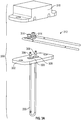
- FIG. 3A shows an exploded view of example 300 assembly that includes a thermocouple 200 connected to a mounting flange 302.
- the conductors (202, 204, not shown) are coupled to terminations 304, 306.
- the terminations 304, 306 are connected directly to the sheath 208 of the thermocouple 200.
- two thermocouple wires are contained in a single thermocouple sheath and separated by potting material.
- thermocouple wires are isolated from each other and they are connected directly to the individual terminations. In this manner, each conductor is supported from the sheath 208 to the terminations 304, 306 without the need for a separate potted transition.
- an insulator 308 surrounds the terminations 304, 306 and insulates them from the flange 302.
- FIG. 3B is a simplified sectional view of a region where the terminations (e.g, in this case, termination 304) passes through the flange 302.
- a glass seal 402 is provided between the termination 304 and the flange 302.
- the insulator 308 of FIG. 3A is omitted from FIG. 3B .
- the conductor 202 is electrically coupled to the termination 204.
- the sheath 208 is connected directly to the termination 304 to provide the support as described above.
- connection to the terminations is by using terminal studs which are torque tightened with the connection which could result in breakage of the terminals.
- the connections shown in the arrangement will address the issue with terminal type of design.
- the connections to the terminations can be contained in connection housing.
- connection housing 310 An example of a connection housing is shown by element 310 in FIG. 3 . It shall be understood that the connection housing 310 can be connected over a connection assembly 312 that is the same or different than that shown in FIG. 3 . Different types of connection assemblies 312 are described below.
- the connectors 314 of the connection assembly 312 can be spring joints or wave springs.
- FIG. 4 shows a cross section of a connection housing 310 connected to the mounting flange 302 by fasteners 406 which can be bolts in one embodiment.
- the housing 310 is used to secure the connection assembly 312 to the terminations 304, 306.
- the housing 310 includes an outer metal portion 402 that surrounds an insert molded inner region 404.
- the insert molded inner region 404 can be formed of a glass-mica composite material in one embodiment.
- the insert molded inner region 404 can be selected such that it has one or more of the following attributes: Dielectric strength properties to support insulation of 19 KV/mm, a working temperature-Up to 600°C, can be molded with metal, has a high structural rigidity (e.g., Young's Modulus-80 Gpa and Flexural strength-90Mpa) and that is non-reactive to general aircraft working environment (Eg: De-icing fluids etc.)
- the insert molded inner region 404 can be sized and arranged to receive the illustrated spring loaded joints 410. As illustrated the spring loaded joints 410 are isolated from the flange by insulator 422.
- the spring loaded joints 410 are circled by wires 420 but this is not required.
- FIG. 5 shows a different cross section of a connection housing 310 connected to the mounting flange 302 by fasteners 406 which can be bolts in one embodiment.
- the housing 310 is used to secure the connection assembly 312 to the terminations 304, 306.
- the housing 310 includes an outer metal portion 402 that surrounds an insert molded inner region 404.
- the insert molded inner region 404 can be formed of a glass-mica composite material in one embodiment.
- the insert molded inner region 404 can be selected in the manner as described above.
- the insert molded inner region 404 can be sized and arranged to receive the illustrated joints 510. As illustrated the joints are isolated from the flange by insulator 422.
- the joints 510 are circled by wires 420 but this is not required.
- wave springs 520 can be used to ensure electrical connection between the joints 510 are the terminations 304, 304.
- the connection could be made by ring terminals.
- the connectors 602 can include ring terminals 604 on one or both ends.
- the housing 310 is, again, connected to the flange 302 by connectors 406 and includes an insert molded inner region 404 sized and arranged to receive the ring terminal 604.
Landscapes
- Physics & Mathematics (AREA)
- General Physics & Mathematics (AREA)
- Measuring Temperature Or Quantity Of Heat (AREA)
Abstract
Description
- This application claims priority to Indian Patent Application No.
201811011117 filed March 26, 2018 - Exemplary embodiments pertain to the art of thermocouples and, in particular, to thermocouples for high temperature applications.
- A thermocouple is an electrical device consisting of two electrical conductors formed of different materials. The conductors are joined together, typically at a distal end of the conductors. In operation, a thermocouple produces a temperature-dependent voltage due to the so-called "thermoelectric effect." The voltage so produced can be interpreted in a manner such that it is used to measure temperature.
- Typically, thermocouple elements used in existing designs will contain both positive and negative conductors packed inside one mineral insulated cable or sheath. The junction where the two conductors are joined in the tip of sheath is used to measure temperature.
- Disclosed is a thermocouple assembly for use in a high-temperature gas path that includes a thermocouple. The thermocouple includes a first conductor and a second conductor, the first and second conductors formed of different materials and coupled to one another by junction, a metal sheath surrounding the first and second conductors wherein the metal sheath is substantially coaxial with the both the first conductor and the second conductor. The assembly also includes: a first termination electrically coupled to the first conductor; a second termination electrically coupled to the second conductor; a first connector configured to couple to the first termination; a second connector configured to couple to the second termination; and a housing configured to cover the first and second terminations and the first and second connectors.
- In one or more prior embodiments, the assembly further includes a mounting flange, the mounting flange surrounding the first and second terminations and configured to fastened to the housing.
- In one or more prior embodiments, the mounting flange is electrically insulated from the first termination by a glass seal.
- In one or more prior embodiments, the thermocouple further includes insulation disposed between the first conductor and the metal sheath.
- In one or more prior embodiments, the insulation is formed of MgO or Al203.
- In one or more prior embodiments, the metal sheath is coaxial with at least one of the first and second conductors.
- In one or more prior embodiments, the metal sheath is formed of one of: Inconel 600, Hastelloy X, Haynes 188 or Haynes 230.
- In one or more prior embodiments, the metal sheath includes an inner layer formed of a different material than the metal sheath.
- In one or more prior embodiments, the first and second terminations are coupled to the metal sheath.
- In one or more prior embodiments, the first and second connectors are spring loaded joints.
- In one or more prior embodiments, the housing includes an outer metal portion and an insert molded inner region within the outer metal portion.
- In one or more prior embodiments, wherein the insert molded inner region is formed of a glass-mica composite material.
- In one or more prior embodiments, the assembly further includes wave springs disposed in the insert molded inner region to hold the connections on to the terminations.
- In one or more prior embodiments, the assembly further includes a first wire encircling the first connection and a second wire encircling the second connection.
- In one or more prior embodiments, the assembly further includes an insulator disposed between the first connector and the mounting flange.
- In one or more prior embodiments, the assembly further includes one or more bolts coupling the housing to the mounting flange.
- In one or more prior embodiments, the first and second connectors are ring connectors.
- The following descriptions should not be considered limiting in any way. With reference to the accompanying drawings, like elements are numbered alike:
-
FIG. 1A is a cross-sectional side view of a prior art thermocouple; -
FIG. 1B is a cross-section ofFIG. 1A ; -
FIG. 2A is a cross-sectional side view of a thermocouple according to one embodiment; -
FIG. 2B is a cross-section ofFIG. 2A according to one embodiment; -
FIG. 2C is a cross-section ofFIG. 2A according to one embodiment taken along one conductor; -
FIG. 2D is a cross-section ofFIG. 2A according to one embodiment taken along a different conductor that conductor; -
FIG. 3A is an exploded view of a thermocouple assembly according to one embodiment that includes a thermocouple, connectors and a housing that connects to a mounting flange of that covers the connectors; -
FIG. 3B is a simplified cross-section of the assembly of 3A in the region where a termination passes through the mounting flange; -
FIG. 4 is a cross-section of a housing installed over connectors according to one embodiment; -
FIG. 5 is a cross-section of a housing installed over connectors according to one embodiment; and -
FIG. 6A is an assembled view of a thermocouple assembly according to one embodiment that includes a thermocouple, connectors having ring terminals on one or both end and a housing that connects to a mounting flange of that covers the connectors; -
FIG. 6B is a cross-section of a housing installed over connectors according to one embodiment. - A detailed description of one or more embodiments of the disclosed apparatus and method are presented herein by way of exemplification and not limitation with reference to the Figures.
-
FIGs. 1A and 1B show an example of aprior art thermocouple 100. Thethermocouple 100 includes twoconductors conductor junction 106 that is used for measuring the temperature. The size of the junction is selected to accommodate the twoconductors - The two conductors, 102, 104 and the
junction 106 are surrounded by ametal sheath 108.Mineral insulation 110 disposed between theconductors conductors metal sheath 108. Such a configuration can be referred to as a mineral-insulated, metal-sheathed (MIMS) construction and very common and covered by industrial standards such as ASTM E608 and IEC 61515. In operation, at least atip 112 of the thermocouple 100 (and most likely, a portion that at least includes the junction 106) is exposed to a hot gas, for example. - As illustrated in
FIGs. 1A and 1B , each of the twoconductors metal sheath 108 also has a longitudinal axis C. This axis is parallel to both axes A and B. Themetal sheath 108 has diameter d1. - In contrast to the prior art, embodiments disclosed herein have coaxial or substantially coaxial configuration of the conductors relative to the outer metal sheath. The term "substantially coaxial" as the term is used herein refer to the situation where the axis of one element not perfectly coaxial with another but is within an outer periphery of the other element.
-
FIGs. 2A and 2B show an example ofthermocouple 200 according to one embodiment. Thethermocouple 200 includes twoconductors conductor junction 206 that is used for measuring the temperature. The size of the junction is selected to accommodate the twoconductors - The two conductors, 202, 204 and the
junction 206 are surrounded by ametal sheath 208.Mineral insulation 210 disposed between theconductors metal sheath 208. In operation, at least atip 212 of the thermocouple 100 (and most likely, a portion that at least includes the junction 106) is exposed to a hot gas, for example. -
FIGs.2B and 2C show a coaxial configuration and a substantially coaxial configuration of thethermocouple 200 ofFIG. 2A taken along line B-B. InFIG. 2B thefirst conductor 202 includes an axis A and the metal sheath includes an axis C that is coaxial with axis A and, thus, are represented as the same element. Themetal sheath 208 has diameter d2. - In
FIG. 2C thefirst conductor 202 includes an axis A and the metal sheath includes an axis C that is slightly offset from axis A but with the outer perimeter 220 of thefirst conductor 202. Such a configuration, as described above, shall be referred to as being "substantially coaxial." In particular, themetal sheath 208 is substantially coaxial with thefirst conductor 202 because axis C is within the outer perimeter 220 of thefirst conductor 202. Similarly, and a shown inFIG. 2D , which is a cross section taken along line C-C inFIG. 2A , themetal sheath 208 is substantially coaxial with the second conductor 203 because axis C is within theouter perimeter 222 of thesecond conductor 204. - The
insulation 210 can be formed of MgO in one embodiment. In another it can be formed of a Al203 fibrous sleeving. In another embodiment insulation is a A1203 or MgO ceramic coating applied by plasma spray. - The
outer sheath 208 can be formed as a single sheath formed over theconductors junction 206, and theinsulation 210. The sheath can be swaged over the insulation in one embodiment. Regardless of how applied, themetal sheath 208 can be formed of Inconel 600, Hastelloy X, Haynes 188 or Haynes 230 to name but a few. While the outer sheath has been shown heretofore as a single layer it shall be understood that it could be formed of two layers. For example the inner layer could be optimized for compatibility with the conductors and the outer layer optimized to withstand high heat. For example, the inner layer could be KP alloy while the outer layer is Haynes 230. OF course the inner layer could be metal foil such as Ti. In one embodiment, the inner layer is formed of a different material than thesheath 208. - The
thermocouple 200 could be formed by first joining theconductors junction 206, and then applying the insulation and then the metal sheath. The assembly could then be bent into a u-shape with the junction being at or near a distal end of the assembly. The above described thermocouple may allow for easier construction with no welding. - In addition, the substantially coaxial type element design of
thermocouple 200 can have faster response times than the prior art. In particular, the time constant/time response is dependent on the convective heat transfer coefficient. The time constant/response will improve if the heat transfer coefficient and surface area exposed to the gas being measured is improved. The time constant is approximated by the lumped heat capacity model. In such a model, the time constant τ is defined as follows:
- In coaxial or substantially coaxial arrangements described above, the surface area of exposure to fluid increases for given volume which helps in improving the time response. The coaxial element allows for minimizing sheath diameter (reduce mass "ρV" and improve response) without compromising dielectric strength. The configuration promotes a preferred cross flow condition (increase effective area "A") regardless of probe orientation to flow.
- In one embodiment, the sheath diameter can be reduced by 50% which will reduce the response time proportionally. For example, d2 (
FIG. 2B ) can be 50% smaller that d1 (FIG. 1B ). Further, such a configuration will allow for increased sheath thickness that can improve high temperature life time of thethermocouple 200.FIG. 3A shows an exploded view of example 300 assembly that includes athermocouple 200 connected to a mountingflange 302. The conductors (202, 204, not shown) are coupled toterminations terminations sheath 208 of thethermocouple 200. Conventionally, two thermocouple wires are contained in a single thermocouple sheath and separated by potting material. In such a case, wire management can be challenging. In embodiments disclosed herein, the two thermocouple wires (conductors 202, 204) are isolated from each other and they are connected directly to the individual terminations. In this manner, each conductor is supported from thesheath 208 to theterminations - In general, an
insulator 308 surrounds theterminations flange 302. -
FIG. 3B is a simplified sectional view of a region where the terminations (e.g, in this case, termination 304) passes through theflange 302. Aglass seal 402 is provided between thetermination 304 and theflange 302. For simplicity, theinsulator 308 ofFIG. 3A is omitted fromFIG. 3B . Theconductor 202 is electrically coupled to thetermination 204. As illustrated, thesheath 208 is connected directly to thetermination 304 to provide the support as described above. - In some prior art applications, connection to the terminations is by using terminal studs which are torque tightened with the connection which could result in breakage of the terminals. Herein, the connections shown in the arrangement will address the issue with terminal type of design. Further, in one embodiment, the connections to the terminations can be contained in connection housing.
- An example of a connection housing is shown by
element 310 inFIG. 3 . It shall be understood that theconnection housing 310 can be connected over aconnection assembly 312 that is the same or different than that shown inFIG. 3 . Different types ofconnection assemblies 312 are described below. Theconnectors 314 of theconnection assembly 312 can be spring joints or wave springs. -
FIG. 4 shows a cross section of aconnection housing 310 connected to the mountingflange 302 byfasteners 406 which can be bolts in one embodiment. - With reference to
FIGs. 3 and4 , thehousing 310 is used to secure theconnection assembly 312 to theterminations housing 310 includes anouter metal portion 402 that surrounds an insert moldedinner region 404. The insert moldedinner region 404 can be formed of a glass-mica composite material in one embodiment. The insert moldedinner region 404 can be selected such that it has one or more of the following attributes: Dielectric strength properties to support insulation of 19 KV/mm, a working temperature-Up to 600°C, can be molded with metal, has a high structural rigidity (e.g., Young's Modulus-80 Gpa and Flexural strength-90Mpa) and that is non-reactive to general aircraft working environment (Eg: De-icing fluids etc.) - The insert molded
inner region 404 can be sized and arranged to receive the illustrated spring loaded joints 410. As illustrated the spring loadedjoints 410 are isolated from the flange byinsulator 422. - As illustrated, the spring loaded
joints 410 are circled bywires 420 but this is not required. -
FIG. 5 shows a different cross section of aconnection housing 310 connected to the mountingflange 302 byfasteners 406 which can be bolts in one embodiment. - Like before, the
housing 310 is used to secure theconnection assembly 312 to theterminations housing 310 includes anouter metal portion 402 that surrounds an insert moldedinner region 404. The insert moldedinner region 404 can be formed of a glass-mica composite material in one embodiment. The insert moldedinner region 404 can be selected in the manner as described above. - The insert molded
inner region 404 can be sized and arranged to receive the illustrated joints 510. As illustrated the joints are isolated from the flange byinsulator 422. - As illustrated, the
joints 510 are circled bywires 420 but this is not required. In the embodiment, wave springs 520 can be used to ensure electrical connection between thejoints 510 are theterminations - In yet another embodiment, rather than using spring loaded joints or a combination of a joint and a wave spring, the connection could be made by ring terminals. For example, and with reference to
FIGs. 6A and 6B , theconnectors 602 can includering terminals 604 on one or both ends. Thehousing 310 is, again, connected to theflange 302 byconnectors 406 and includes an insert moldedinner region 404 sized and arranged to receive thering terminal 604. - The term "about" is intended to include the degree of error associated with measurement of the particular quantity based upon the equipment available at the time of filing the application.
- The terminology used herein is for the purpose of describing particular embodiments only and is not intended to be limiting of the present disclosure. As used herein, the singular forms "a", "an" and "the" are intended to include the plural forms as well, unless the context clearly indicates otherwise. It will be further understood that the terms "comprises" and/or "comprising," when used in this specification, specify the presence of stated features, integers, steps, operations, elements, and/or components, but do not preclude the presence or addition of one or more other features, integers, steps, operations, element components, and/or groups thereof.
- While the present disclosure has been described with reference to an exemplary embodiment or embodiments, it will be understood by those skilled in the art that various changes may be made and equivalents may be substituted for elements thereof without departing from the scope of the present disclosure. In addition, many modifications may be made to adapt a particular situation or material to the teachings of the present disclosure without departing from the essential scope thereof. Therefore, it is intended that the present disclosure not be limited to the particular embodiment disclosed as the best mode contemplated for carrying out this present disclosure, but that the present disclosure will include all embodiments falling within the scope of the claims.
Claims (15)
- A thermocouple assembly for use in a high-temperature gas path, the assembly comprising:a thermocouple that includes:a first conductor and a second conductor, the first and second conductors formed of different materials and coupled to one another by junction;a metal sheath surrounding the first and second conductors wherein the metal sheath is substantially coaxial with the both the first conductor and the second conductor;a first termination electrically coupled to the first conductor;a second termination electrically coupled to the second conductor;a first connector configured to couple to the first termination;a second connector configured to couple to the second termination; anda housing configured to cover the first and second terminations and the first and second connectors.
- The thermocouple assembly of claim 1, further comprising a mounting flange, the mounting flange surrounding the first and second terminations and configured to fastened to the housing.
- The thermocouple assembly of claim 2, wherein the mounting flange is electrically insulated from the first termination by a glass seal.
- The thermocouple assembly of claim 1, 2 or 3, wherein the thermocouple further includes insulation disposed between the first conductor and the metal sheath.
- The thermocouple assembly of claim 4, wherein the insulation is formed of MgO or Al2O3.
- The thermocouple assembly of any preceding claim, wherein the metal sheath is coaxial with at least one of the first and second conductors.
- The thermocouple assembly of any preceding claim, wherein the metal sheath is formed of one of: Inconel 600, Hastelloy X, Haynes 188 or Haynes 230.
- The thermocouple assembly of claim 7, wherein the metal sheath includes an inner layer formed of a different material than the metal sheath.
- The thermocouple assembly of any preceding claim, wherein the first and second terminations are coupled to the metal sheath.
- The thermocouple assembly of any preceding claim, wherein the first and second connectors are spring loaded joints.
- The thermocouple assembly of any preceding claim, wherein the housing includes an outer metal portion and an insert molded inner region within the outer metal portion.
- The thermocouple assembly of claim 11, wherein the insert molded inner region is formed of a glass-mica composite material.
- The thermocouple assembly of claim 11 or 12, further including wave springs disposed in the insert molded inner region to hold the connections on to the terminations.
- The thermocouple assembly of any preceding claim, further including a first wire encircling the first connection and a second wire encircling the second connection.
- The thermocouple assembly of any of claims 2 to 14, further comprising an insulator disposed between the first connector and the mounting flange.
Applications Claiming Priority (1)
| Application Number | Priority Date | Filing Date | Title |
|---|---|---|---|
| IN201811011117 | 2018-03-26 |
Publications (3)
| Publication Number | Publication Date |
|---|---|
| EP3557207A2 true EP3557207A2 (en) | 2019-10-23 |
| EP3557207A3 EP3557207A3 (en) | 2020-02-12 |
| EP3557207B1 EP3557207B1 (en) | 2021-12-29 |
Family
ID=65911071
Family Applications (1)
| Application Number | Title | Priority Date | Filing Date |
|---|---|---|---|
| EP19164872.4A Active EP3557207B1 (en) | 2018-03-26 | 2019-03-25 | Coaxial high temperature thermocouple |
Country Status (2)
| Country | Link |
|---|---|
| US (1) | US10935437B2 (en) |
| EP (1) | EP3557207B1 (en) |
Families Citing this family (1)
| Publication number | Priority date | Publication date | Assignee | Title |
|---|---|---|---|---|
| JP7278035B2 (en) * | 2018-06-20 | 2023-05-19 | 新光電気工業株式会社 | Electrostatic chuck, substrate fixing device |
Family Cites Families (15)
| Publication number | Priority date | Publication date | Assignee | Title |
|---|---|---|---|---|
| US2431953A (en) | 1947-12-02 | High-frequency thermocouple | ||
| US2307626A (en) | 1940-07-23 | 1943-01-05 | Edison Inc Thomas A | Resistance thermometer |
| GB832605A (en) | 1955-10-17 | 1960-04-13 | Fenwal Inc | Improvements in or relating to temperature sensing apparatus |
| US3199967A (en) | 1960-08-17 | 1965-08-10 | Haveg Industries Inc | Method of producing hermetic seal |
| US4808794A (en) * | 1987-07-10 | 1989-02-28 | Watlow Industries, Inc. | Thermostatically controlled electric immersion heating element |
| FI87494C (en) | 1991-03-19 | 1993-01-11 | Beamex Ab Oy | Comparison coupling for thermopair measurement |
| US5386173A (en) * | 1992-08-28 | 1995-01-31 | General Electric Company | One-piece thermally resistant gimbal device for a replaceable headlamp bulb |
| GB2341975B (en) | 1998-09-24 | 2003-11-26 | Solartron Group Ltd | Thermocouple and method of manufacture |
| JP4016627B2 (en) | 2000-11-22 | 2007-12-05 | 株式会社デンソー | Temperature sensor |
| US6798214B1 (en) | 2002-10-01 | 2004-09-28 | Process Instruments, Inc. | Self-adjusting resistance standard |
| US7465086B1 (en) * | 2005-03-05 | 2008-12-16 | Foreman Instrumentation & Controls, Inc. | Adjustable length thermowell |
| KR100648416B1 (en) * | 2005-09-02 | 2006-11-24 | 고려전자주식회사 | Automotive temperature sensor |
| GB201005509D0 (en) * | 2010-03-31 | 2010-05-19 | Cambridge Entpr Ltd | Thermocouple apparatus and method |
| JP5956071B2 (en) * | 2013-05-16 | 2016-07-20 | 矢崎総業株式会社 | Connecting terminal |
| US20160243036A1 (en) * | 2015-02-25 | 2016-08-25 | Intelgenx Corp. | Film dosage forms containing amorphous active agents |
-
2018
- 2018-05-21 US US15/984,558 patent/US10935437B2/en active Active
-
2019
- 2019-03-25 EP EP19164872.4A patent/EP3557207B1/en active Active
Also Published As
| Publication number | Publication date |
|---|---|
| US20190293496A1 (en) | 2019-09-26 |
| US10935437B2 (en) | 2021-03-02 |
| EP3557207A3 (en) | 2020-02-12 |
| EP3557207B1 (en) | 2021-12-29 |
Similar Documents
| Publication | Publication Date | Title |
|---|---|---|
| CN102047087B (en) | High vibration film rtd sensor | |
| US7665890B2 (en) | Temperature sensor assembly and method of manufacturing thereof | |
| KR101113532B1 (en) | Temperature sensor for a resistance thermometer, in particular for use in the exhaust gas system of combustion engines | |
| US10345156B2 (en) | Temperature sensor and method for the production of a temperature sensor | |
| US5711608A (en) | Thermocouple assemblies | |
| US2379530A (en) | Resistance element | |
| US8197134B2 (en) | Thermocouple head unit | |
| US20110222583A1 (en) | Apparatus for determining and/or monitoring a process variable | |
| CN115876340B (en) | Temperature probe | |
| JP5618310B1 (en) | Temperature sensor for high temperature | |
| US20090279586A1 (en) | Temperature sensor | |
| EP3339825B1 (en) | High-temperature exhaust sensor | |
| EP3557207B1 (en) | Coaxial high temperature thermocouple | |
| US20210310873A1 (en) | Tubular wire shielding for an exhaust gas temperature sensor arrangement, exhaust gas temperature sensor arrangement and method for assembling an exhaust gas temperature sensor arrangement | |
| CN117516739A (en) | Aviation temperature sensor and assembly method | |
| JP4776762B2 (en) | Thermocouple device | |
| EP4063815A1 (en) | Temperature-measuring device | |
| JP4986879B2 (en) | Thermocouple adapter structure and sheath thermocouple | |
| EP0989393A2 (en) | Thermocouple and method of manufacture | |
| JPH01267427A (en) | Temperature detector for monitoring surface temperature | |
| GB2184554A (en) | Temperature monitoring devices for use with mineral insulated cables | |
| US20250130118A1 (en) | Resistance temperature detectors | |
| JP7165714B2 (en) | Feedthroughs for electrical heating devices, electrical heating devices comprising such feedthroughs, systems comprising such feedthroughs, and methods for manufacturing such feedthroughs | |
| JPS6219952Y2 (en) | ||
| EP3772638A1 (en) | Thermal sensor wire and method of assembling the same |
Legal Events
| Date | Code | Title | Description |
|---|---|---|---|
| PUAI | Public reference made under article 153(3) epc to a published international application that has entered the european phase |
Free format text: ORIGINAL CODE: 0009012 |
|
| STAA | Information on the status of an ep patent application or granted ep patent |
Free format text: STATUS: THE APPLICATION HAS BEEN PUBLISHED |
|
| AK | Designated contracting states |
Kind code of ref document: A2 Designated state(s): AL AT BE BG CH CY CZ DE DK EE ES FI FR GB GR HR HU IE IS IT LI LT LU LV MC MK MT NL NO PL PT RO RS SE SI SK SM TR |
|
| AX | Request for extension of the european patent |
Extension state: BA ME |
|
| PUAL | Search report despatched |
Free format text: ORIGINAL CODE: 0009013 |
|
| AK | Designated contracting states |
Kind code of ref document: A3 Designated state(s): AL AT BE BG CH CY CZ DE DK EE ES FI FR GB GR HR HU IE IS IT LI LT LU LV MC MK MT NL NO PL PT RO RS SE SI SK SM TR |
|
| AX | Request for extension of the european patent |
Extension state: BA ME |
|
| RIC1 | Information provided on ipc code assigned before grant |
Ipc: G01K 7/02 20060101AFI20200108BHEP Ipc: G01K 13/02 20060101ALI20200108BHEP |
|
| STAA | Information on the status of an ep patent application or granted ep patent |
Free format text: STATUS: REQUEST FOR EXAMINATION WAS MADE |
|
| 17P | Request for examination filed |
Effective date: 20200812 |
|
| RBV | Designated contracting states (corrected) |
Designated state(s): AL AT BE BG CH CY CZ DE DK EE ES FI FR GB GR HR HU IE IS IT LI LT LU LV MC MK MT NL NO PL PT RO RS SE SI SK SM TR |
|
| STAA | Information on the status of an ep patent application or granted ep patent |
Free format text: STATUS: EXAMINATION IS IN PROGRESS |
|
| 17Q | First examination report despatched |
Effective date: 20201214 |
|
| GRAP | Despatch of communication of intention to grant a patent |
Free format text: ORIGINAL CODE: EPIDOSNIGR1 |
|
| STAA | Information on the status of an ep patent application or granted ep patent |
Free format text: STATUS: GRANT OF PATENT IS INTENDED |
|
| INTG | Intention to grant announced |
Effective date: 20210721 |
|
| RIN1 | Information on inventor provided before grant (corrected) |
Inventor name: MOTHE, VENKATA ANIL KUMAR Inventor name: PHILLIPS, RICHARD WILLIAM |
|
| GRAS | Grant fee paid |
Free format text: ORIGINAL CODE: EPIDOSNIGR3 |
|
| GRAA | (expected) grant |
Free format text: ORIGINAL CODE: 0009210 |
|
| STAA | Information on the status of an ep patent application or granted ep patent |
Free format text: STATUS: THE PATENT HAS BEEN GRANTED |
|
| AK | Designated contracting states |
Kind code of ref document: B1 Designated state(s): AL AT BE BG CH CY CZ DE DK EE ES FI FR GB GR HR HU IE IS IT LI LT LU LV MC MK MT NL NO PL PT RO RS SE SI SK SM TR |
|
| REG | Reference to a national code |
Ref country code: GB Ref legal event code: FG4D |
|
| REG | Reference to a national code |
Ref country code: CH Ref legal event code: EP |
|
| REG | Reference to a national code |
Ref country code: DE Ref legal event code: R096 Ref document number: 602019010361 Country of ref document: DE |
|
| REG | Reference to a national code |
Ref country code: AT Ref legal event code: REF Ref document number: 1459023 Country of ref document: AT Kind code of ref document: T Effective date: 20220115 |
|
| REG | Reference to a national code |
Ref country code: IE Ref legal event code: FG4D |
|
| REG | Reference to a national code |
Ref country code: LT Ref legal event code: MG9D |
|
| PG25 | Lapsed in a contracting state [announced via postgrant information from national office to epo] |
Ref country code: RS Free format text: LAPSE BECAUSE OF FAILURE TO SUBMIT A TRANSLATION OF THE DESCRIPTION OR TO PAY THE FEE WITHIN THE PRESCRIBED TIME-LIMIT Effective date: 20211229 Ref country code: LT Free format text: LAPSE BECAUSE OF FAILURE TO SUBMIT A TRANSLATION OF THE DESCRIPTION OR TO PAY THE FEE WITHIN THE PRESCRIBED TIME-LIMIT Effective date: 20211229 Ref country code: FI Free format text: LAPSE BECAUSE OF FAILURE TO SUBMIT A TRANSLATION OF THE DESCRIPTION OR TO PAY THE FEE WITHIN THE PRESCRIBED TIME-LIMIT Effective date: 20211229 Ref country code: BG Free format text: LAPSE BECAUSE OF FAILURE TO SUBMIT A TRANSLATION OF THE DESCRIPTION OR TO PAY THE FEE WITHIN THE PRESCRIBED TIME-LIMIT Effective date: 20220329 |
|
| REG | Reference to a national code |
Ref country code: NL Ref legal event code: MP Effective date: 20211229 |
|
| REG | Reference to a national code |
Ref country code: AT Ref legal event code: MK05 Ref document number: 1459023 Country of ref document: AT Kind code of ref document: T Effective date: 20211229 |
|
| PG25 | Lapsed in a contracting state [announced via postgrant information from national office to epo] |
Ref country code: SE Free format text: LAPSE BECAUSE OF FAILURE TO SUBMIT A TRANSLATION OF THE DESCRIPTION OR TO PAY THE FEE WITHIN THE PRESCRIBED TIME-LIMIT Effective date: 20211229 Ref country code: NO Free format text: LAPSE BECAUSE OF FAILURE TO SUBMIT A TRANSLATION OF THE DESCRIPTION OR TO PAY THE FEE WITHIN THE PRESCRIBED TIME-LIMIT Effective date: 20220329 Ref country code: LV Free format text: LAPSE BECAUSE OF FAILURE TO SUBMIT A TRANSLATION OF THE DESCRIPTION OR TO PAY THE FEE WITHIN THE PRESCRIBED TIME-LIMIT Effective date: 20211229 Ref country code: HR Free format text: LAPSE BECAUSE OF FAILURE TO SUBMIT A TRANSLATION OF THE DESCRIPTION OR TO PAY THE FEE WITHIN THE PRESCRIBED TIME-LIMIT Effective date: 20211229 Ref country code: GR Free format text: LAPSE BECAUSE OF FAILURE TO SUBMIT A TRANSLATION OF THE DESCRIPTION OR TO PAY THE FEE WITHIN THE PRESCRIBED TIME-LIMIT Effective date: 20220330 |
|
| PG25 | Lapsed in a contracting state [announced via postgrant information from national office to epo] |
Ref country code: NL Free format text: LAPSE BECAUSE OF FAILURE TO SUBMIT A TRANSLATION OF THE DESCRIPTION OR TO PAY THE FEE WITHIN THE PRESCRIBED TIME-LIMIT Effective date: 20211229 |
|
| PG25 | Lapsed in a contracting state [announced via postgrant information from national office to epo] |
Ref country code: SM Free format text: LAPSE BECAUSE OF FAILURE TO SUBMIT A TRANSLATION OF THE DESCRIPTION OR TO PAY THE FEE WITHIN THE PRESCRIBED TIME-LIMIT Effective date: 20211229 Ref country code: SK Free format text: LAPSE BECAUSE OF FAILURE TO SUBMIT A TRANSLATION OF THE DESCRIPTION OR TO PAY THE FEE WITHIN THE PRESCRIBED TIME-LIMIT Effective date: 20211229 Ref country code: RO Free format text: LAPSE BECAUSE OF FAILURE TO SUBMIT A TRANSLATION OF THE DESCRIPTION OR TO PAY THE FEE WITHIN THE PRESCRIBED TIME-LIMIT Effective date: 20211229 Ref country code: PT Free format text: LAPSE BECAUSE OF FAILURE TO SUBMIT A TRANSLATION OF THE DESCRIPTION OR TO PAY THE FEE WITHIN THE PRESCRIBED TIME-LIMIT Effective date: 20220429 Ref country code: ES Free format text: LAPSE BECAUSE OF FAILURE TO SUBMIT A TRANSLATION OF THE DESCRIPTION OR TO PAY THE FEE WITHIN THE PRESCRIBED TIME-LIMIT Effective date: 20211229 Ref country code: EE Free format text: LAPSE BECAUSE OF FAILURE TO SUBMIT A TRANSLATION OF THE DESCRIPTION OR TO PAY THE FEE WITHIN THE PRESCRIBED TIME-LIMIT Effective date: 20211229 Ref country code: CZ Free format text: LAPSE BECAUSE OF FAILURE TO SUBMIT A TRANSLATION OF THE DESCRIPTION OR TO PAY THE FEE WITHIN THE PRESCRIBED TIME-LIMIT Effective date: 20211229 |
|
| PG25 | Lapsed in a contracting state [announced via postgrant information from national office to epo] |
Ref country code: PL Free format text: LAPSE BECAUSE OF FAILURE TO SUBMIT A TRANSLATION OF THE DESCRIPTION OR TO PAY THE FEE WITHIN THE PRESCRIBED TIME-LIMIT Effective date: 20211229 Ref country code: AT Free format text: LAPSE BECAUSE OF FAILURE TO SUBMIT A TRANSLATION OF THE DESCRIPTION OR TO PAY THE FEE WITHIN THE PRESCRIBED TIME-LIMIT Effective date: 20211229 |
|
| PG25 | Lapsed in a contracting state [announced via postgrant information from national office to epo] |
Ref country code: IS Free format text: LAPSE BECAUSE OF FAILURE TO SUBMIT A TRANSLATION OF THE DESCRIPTION OR TO PAY THE FEE WITHIN THE PRESCRIBED TIME-LIMIT Effective date: 20220429 |
|
| REG | Reference to a national code |
Ref country code: DE Ref legal event code: R097 Ref document number: 602019010361 Country of ref document: DE |
|
| PG25 | Lapsed in a contracting state [announced via postgrant information from national office to epo] |
Ref country code: MC Free format text: LAPSE BECAUSE OF FAILURE TO SUBMIT A TRANSLATION OF THE DESCRIPTION OR TO PAY THE FEE WITHIN THE PRESCRIBED TIME-LIMIT Effective date: 20211229 Ref country code: DK Free format text: LAPSE BECAUSE OF FAILURE TO SUBMIT A TRANSLATION OF THE DESCRIPTION OR TO PAY THE FEE WITHIN THE PRESCRIBED TIME-LIMIT Effective date: 20211229 Ref country code: AL Free format text: LAPSE BECAUSE OF FAILURE TO SUBMIT A TRANSLATION OF THE DESCRIPTION OR TO PAY THE FEE WITHIN THE PRESCRIBED TIME-LIMIT Effective date: 20211229 |
|
| REG | Reference to a national code |
Ref country code: CH Ref legal event code: PL |
|
| PLBE | No opposition filed within time limit |
Free format text: ORIGINAL CODE: 0009261 |
|
| STAA | Information on the status of an ep patent application or granted ep patent |
Free format text: STATUS: NO OPPOSITION FILED WITHIN TIME LIMIT |
|
| 26N | No opposition filed |
Effective date: 20220930 |
|
| REG | Reference to a national code |
Ref country code: BE Ref legal event code: MM Effective date: 20220331 |
|
| PG25 | Lapsed in a contracting state [announced via postgrant information from national office to epo] |
Ref country code: LU Free format text: LAPSE BECAUSE OF NON-PAYMENT OF DUE FEES Effective date: 20220325 Ref country code: LI Free format text: LAPSE BECAUSE OF NON-PAYMENT OF DUE FEES Effective date: 20220331 Ref country code: IE Free format text: LAPSE BECAUSE OF NON-PAYMENT OF DUE FEES Effective date: 20220325 Ref country code: CH Free format text: LAPSE BECAUSE OF NON-PAYMENT OF DUE FEES Effective date: 20220331 |
|
| PG25 | Lapsed in a contracting state [announced via postgrant information from national office to epo] |
Ref country code: SI Free format text: LAPSE BECAUSE OF FAILURE TO SUBMIT A TRANSLATION OF THE DESCRIPTION OR TO PAY THE FEE WITHIN THE PRESCRIBED TIME-LIMIT Effective date: 20211229 Ref country code: BE Free format text: LAPSE BECAUSE OF NON-PAYMENT OF DUE FEES Effective date: 20220331 |
|
| PG25 | Lapsed in a contracting state [announced via postgrant information from national office to epo] |
Ref country code: IT Free format text: LAPSE BECAUSE OF FAILURE TO SUBMIT A TRANSLATION OF THE DESCRIPTION OR TO PAY THE FEE WITHIN THE PRESCRIBED TIME-LIMIT Effective date: 20211229 |
|
| PG25 | Lapsed in a contracting state [announced via postgrant information from national office to epo] |
Ref country code: MK Free format text: LAPSE BECAUSE OF FAILURE TO SUBMIT A TRANSLATION OF THE DESCRIPTION OR TO PAY THE FEE WITHIN THE PRESCRIBED TIME-LIMIT Effective date: 20211229 Ref country code: CY Free format text: LAPSE BECAUSE OF FAILURE TO SUBMIT A TRANSLATION OF THE DESCRIPTION OR TO PAY THE FEE WITHIN THE PRESCRIBED TIME-LIMIT Effective date: 20211229 |
|
| PG25 | Lapsed in a contracting state [announced via postgrant information from national office to epo] |
Ref country code: HU Free format text: LAPSE BECAUSE OF FAILURE TO SUBMIT A TRANSLATION OF THE DESCRIPTION OR TO PAY THE FEE WITHIN THE PRESCRIBED TIME-LIMIT; INVALID AB INITIO Effective date: 20190325 |
|
| PG25 | Lapsed in a contracting state [announced via postgrant information from national office to epo] |
Ref country code: TR Free format text: LAPSE BECAUSE OF FAILURE TO SUBMIT A TRANSLATION OF THE DESCRIPTION OR TO PAY THE FEE WITHIN THE PRESCRIBED TIME-LIMIT Effective date: 20211229 |
|
| PG25 | Lapsed in a contracting state [announced via postgrant information from national office to epo] |
Ref country code: MT Free format text: LAPSE BECAUSE OF FAILURE TO SUBMIT A TRANSLATION OF THE DESCRIPTION OR TO PAY THE FEE WITHIN THE PRESCRIBED TIME-LIMIT Effective date: 20211229 |
|
| P01 | Opt-out of the competence of the unified patent court (upc) registered |
Free format text: CASE NUMBER: UPC_APP_0017955_3557207/2025 Effective date: 20251217 |
|
| PGFP | Annual fee paid to national office [announced via postgrant information from national office to epo] |
Ref country code: GB Payment date: 20260219 Year of fee payment: 8 |
|
| PGFP | Annual fee paid to national office [announced via postgrant information from national office to epo] |
Ref country code: DE Payment date: 20260219 Year of fee payment: 8 |
|
| PGFP | Annual fee paid to national office [announced via postgrant information from national office to epo] |
Ref country code: FR Payment date: 20260220 Year of fee payment: 8 |