EP3557092B1 - Matériaux pour ensemble de frein à disque à dissipation thermique amorti - Google Patents
Matériaux pour ensemble de frein à disque à dissipation thermique amorti Download PDFInfo
- Publication number
- EP3557092B1 EP3557092B1 EP19178803.3A EP19178803A EP3557092B1 EP 3557092 B1 EP3557092 B1 EP 3557092B1 EP 19178803 A EP19178803 A EP 19178803A EP 3557092 B1 EP3557092 B1 EP 3557092B1
- Authority
- EP
- European Patent Office
- Prior art keywords
- friction
- disk
- stator
- rotor
- disks
- Prior art date
- Legal status (The legal status is an assumption and is not a legal conclusion. Google has not performed a legal analysis and makes no representation as to the accuracy of the status listed.)
- Active
Links
Images

Classifications
-
- F—MECHANICAL ENGINEERING; LIGHTING; HEATING; WEAPONS; BLASTING
- F16—ENGINEERING ELEMENTS AND UNITS; GENERAL MEASURES FOR PRODUCING AND MAINTAINING EFFECTIVE FUNCTIONING OF MACHINES OR INSTALLATIONS; THERMAL INSULATION IN GENERAL
- F16D—COUPLINGS FOR TRANSMITTING ROTATION; CLUTCHES; BRAKES
- F16D65/00—Parts or details
- F16D65/0006—Noise or vibration control
-
- F—MECHANICAL ENGINEERING; LIGHTING; HEATING; WEAPONS; BLASTING
- F16—ENGINEERING ELEMENTS AND UNITS; GENERAL MEASURES FOR PRODUCING AND MAINTAINING EFFECTIVE FUNCTIONING OF MACHINES OR INSTALLATIONS; THERMAL INSULATION IN GENERAL
- F16D—COUPLINGS FOR TRANSMITTING ROTATION; CLUTCHES; BRAKES
- F16D55/00—Brakes with substantially-radial braking surfaces pressed together in axial direction, e.g. disc brakes
- F16D55/24—Brakes with substantially-radial braking surfaces pressed together in axial direction, e.g. disc brakes with a plurality of axially-movable discs, lamellae, or pads, pressed from one side towards an axially-located member
- F16D55/26—Brakes with substantially-radial braking surfaces pressed together in axial direction, e.g. disc brakes with a plurality of axially-movable discs, lamellae, or pads, pressed from one side towards an axially-located member without self-tightening action
- F16D55/36—Brakes with a plurality of rotating discs all lying side by side
- F16D55/40—Brakes with a plurality of rotating discs all lying side by side actuated by a fluid-pressure device arranged in or one the brake
-
- F—MECHANICAL ENGINEERING; LIGHTING; HEATING; WEAPONS; BLASTING
- F16—ENGINEERING ELEMENTS AND UNITS; GENERAL MEASURES FOR PRODUCING AND MAINTAINING EFFECTIVE FUNCTIONING OF MACHINES OR INSTALLATIONS; THERMAL INSULATION IN GENERAL
- F16D—COUPLINGS FOR TRANSMITTING ROTATION; CLUTCHES; BRAKES
- F16D65/00—Parts or details
- F16D65/02—Braking members; Mounting thereof
- F16D65/12—Discs; Drums for disc brakes
- F16D65/125—Discs; Drums for disc brakes characterised by the material used for the disc body
- F16D65/126—Discs; Drums for disc brakes characterised by the material used for the disc body the material being of low mechanical strength, e.g. carbon, beryllium; Torque transmitting members therefor
-
- F—MECHANICAL ENGINEERING; LIGHTING; HEATING; WEAPONS; BLASTING
- F16—ENGINEERING ELEMENTS AND UNITS; GENERAL MEASURES FOR PRODUCING AND MAINTAINING EFFECTIVE FUNCTIONING OF MACHINES OR INSTALLATIONS; THERMAL INSULATION IN GENERAL
- F16D—COUPLINGS FOR TRANSMITTING ROTATION; CLUTCHES; BRAKES
- F16D55/00—Brakes with substantially-radial braking surfaces pressed together in axial direction, e.g. disc brakes
- F16D2055/0004—Parts or details of disc brakes
- F16D2055/0058—Fully lined, i.e. braking surface extending over the entire disc circumference
-
- F—MECHANICAL ENGINEERING; LIGHTING; HEATING; WEAPONS; BLASTING
- F16—ENGINEERING ELEMENTS AND UNITS; GENERAL MEASURES FOR PRODUCING AND MAINTAINING EFFECTIVE FUNCTIONING OF MACHINES OR INSTALLATIONS; THERMAL INSULATION IN GENERAL
- F16D—COUPLINGS FOR TRANSMITTING ROTATION; CLUTCHES; BRAKES
- F16D65/00—Parts or details
- F16D65/02—Braking members; Mounting thereof
- F16D2065/13—Parts or details of discs or drums
- F16D2065/1304—Structure
- F16D2065/132—Structure layered
Definitions
- the disclosure relates generally to aircraft brake systems, and more particularly to materials for use in aircraft brake systems.
- Aircraft brake assemblies encounter large amounts of torque during use.
- the aircraft brake assemblies for large aircraft may exhibit vibrations during use, potentially making the brake assembly less effective and potentially causing structural damage during operation.
- Carbon friction disks used in brake systems tend to have high compressive strength. However, the carbon friction disks may be poor at damping vibrations.
- the present invention provides a disk brake system in accordance with claim 1.
- the present invention provides a friction disk for an aircraft brake system in accordance with claim 8.
- An aircraft brake system such as disk brake system 20 in FIG. 1 , may be used to slow an aircraft while the aircraft is on the ground, for example, during landing.
- a disk brake system may comprise a combination of split friction disk assemblies and/or solid disk assemblies. These split friction disk assemblies and/or solid disk assemblies may be arranged together in any suitable pattern or position.
- the brake systems described herein employ carbon composite disks that tend to suffer less vibration and tend to generate less brake noise than conventional carbon composite disks brake systems.
- the split friction disks may comprise a carbon foam damping feature between halves of a split disk.
- a disk brake system 20 is illustrated according to various embodiments.
- the disk brake system 20 may be used to reduce the speed of a wheel of an aircraft.
- An A-R axis has been included in the drawings to illustrate the axial (A) and radial (R) directions.
- the system may include a wheel 10 supported for rotation around an axle 12 by bearings 14.
- the wheel 10 includes rims 16 for supporting a tire, and a series of axially extending rotor splines 18 (one shown). Rotation of the wheel 10 is modulated by the disk brake system 20.
- the disk brake system 20 includes a torque flange 22, a torque tube 24, a plurality of pistons 26 (one shown), a pressure plate 30, and an end plate 32.
- the pressure plate 30 and the end plate 32 are annular disks.
- the torque tube 24 is an elongated annular structure that includes a reaction plate 34 and a series of axially extending stator splines 36 (one shown).
- the reaction plate 34 and stator splines 36 may be integral with the torque tube 24 as shown in FIG. 1 , or attached as separate components.
- the disk brake system 20 also includes a plurality of friction disks 38.
- the plurality of friction disks 38 includes at least one non-rotatable friction disk, also known as a stator friction disk 40, and at least one rotatable friction disk, also known as a rotor friction disk 42.
- Each of the plurality of friction disks 38 includes an attachment structure.
- each of the stator friction disks 40 includes a plurality of stator lugs 44 at circumferentially spaced positions around the stator friction disk 40 as an attachment structure.
- each of the rotor friction disks 42 includes a plurality of rotor lugs 46 at circumferentially spaced positions around the rotor friction disk 42 as an attachment structure.
- the pressure plate 30, end plate 32, and friction disks 38 are all annular disks.
- the torque flange 22 is mounted to the axle 12.
- the torque tube 24 is bolted to the torque flange 22 such that the reaction plate 34 is near an axial center of the wheel 10.
- the end plate 32 is connected to a surface of the reaction plate 34 facing axially away from the axial center of the wheel 10.
- the stator splines 36 support the pressure plate 30 so that the pressure plate 30 is also non-rotatable.
- the stator splines 36 also support the stator friction disks 40.
- the stator friction disks 40 engage the stator splines 36 with gaps formed between the stator lugs 44.
- the rotor friction disks 42 engage the rotor splines 18 with gaps formed between the rotor lugs 46.
- the rotor friction disks 42 are rotatable by virtue of their engagement with the rotor splines 18 of the wheel 10.
- the rotor friction disks 42 are arranged with the end plate 32 on one end, the pressure plate 30 on the other end, and the stator friction disks 40 interleaved so that the rotor friction disks 42 are adjacent to non-rotatable friction components.
- the number of rotor friction disks 42 and stator friction disks 40 may vary according to the brake assembly design.
- the pistons 26 are connected to the torque flange 22 at circumferentially spaced positions around the torque flange 22.
- the pistons 26 face axially toward the wheel 10 and include pucks 54 that contact a side of the pressure plate 30 opposite the rotor friction disks 42.
- the pistons 26 may be powered electrically, hydraulically or pneumatically.
- the pressure plate 30 may be adjacent to a rotor friction disk 42.
- a stator friction disk 40 may be adjacent to the rotor friction disk 42, and the stator friction disk 40 and the rotor friction disk 42 may be positioned axially between the pressure plate 30 and an end plate 32.
- the plurality of friction disks 38 may be made up of a plurality of stator friction disks 40 and a plurality of rotor friction disks 42, wherein the locations of the stator friction disks 40 alternate axially with the locations of the rotor friction disks 42 between the pressure plate 30 and the end plate 32. There may be one more rotor friction disk 42 than stator friction disks 40 in the plurality of friction disks 38.
- the disk brake systems contemplated herein may have any number of rotor friction disks 42 and/or stator friction disks 40, such as 5,4; 4,3; and 3,2, respectively. Conversely, there may be one more stator friction disk 40 than rotor friction disks 42 in the plurality of friction disks 38, or the number of stator friction disks 40 and rotor friction disks 42 may be equal.
- At least one of the friction disks 38 is a split friction disk.
- the at least one split friction disk may be a rotor split friction disk or a stator split friction disk.
- a stator split friction disk 95 may comprise friction disk halves 82 separated by a damping feature 50.
- the damping feature 50 may comprise a carbon foam material which is less dense than the carbon material of the friction disk halves 82.
- at least one of the plurality of friction disks 38 may be a rotor solid friction disk or a stator solid friction disk.
- a split friction disk may be positioned anywhere within the plurality of friction disks 38.
- the stator split friction disk 95 may be positioned in a middle position of the plurality of friction disks 38.
- the middle position as used herein, may refer to the position on either side of which there is an equal number of friction disks 38.
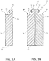
- FIG. 2A shows a cross-sectional view of a split friction disk first half 82.
- FIG. 2B shows a cross-sectional view of a stator split friction disk 95.
- the stator split friction disk 95 includes two disk halves: a split friction disk first half 82 and a split friction disk second half 83.
- Each disk half 82 and 83 includes an attachment structure in the form of lug half 45, a friction surface 56, and a non-friction surface 58.
- the friction surface 56 may be at an axial end of the disk halves 82 and 83.
- the friction surface 56 may be configured for operationally engaging a corresponding friction surface of another disk brake system component, such as a rotor friction disk 42.
- the non-friction surface 58 may be located at an axial end of the disk halves 82 and 83, such as on a side opposite of the friction surface 56.
- the disk halves 82 and 83 further include an inner diameter surface 84 and a first outer diameter surface 86.
- the inner diameter surface 84 may be located at a radially inward facing edge of the disk halves 82 and 83.
- the first outer diameter surface 86 may be located at a radially outward facing edge of the disk halves 82 and 83.
- the friction surface 56 extends radially between the inner diameter surface 84 and a second outer diameter surface 52.
- the non-friction surface 58 extends radially between the inner diameter surface 84 and the first outer diameter surface 86.
- the non-friction surface 58 may be parallel to the friction surface 56.
- Each disk half 82 and 83 may include an attachment structure in the form of a lug half 45.
- the lug half 45 may project radially outward from the first outer diameter surface 86.
- the disk halves 82 and 83 may be secured to each other by a fastening device.
- the corresponding non-friction surfaces 58 of the two disk halves 82 and 83 are held in contact with a damping feature 50 between them, they do not form a continuous structure. That is, in various embodiments the corresponding non-friction surfaces 58 are not bonded to each other, in any way, but are held together by the fastening device. However, in some embodiments, the corresponding non-friction surfaces 58 may be bonded together.
- the damping feature 50 may be positioned between the non-friction surfaces 58 of the disk halves 82 and 83.
- the damping feature 50 may be comprised of a less dense material than the material from which the stator friction disks 40 are comprised.
- the damping feature 50 comprises a carbon foam.
- Carbon foams are made by several manufacturers, such as CFOAM® manufactured by Touchstone Research Laboratory, Ltd., and Duocel® Carbon Foam manufactured by ERG Aerospace Corporation.
- Carbon foam comprises a lightweight, porous carbon structure.
- the carbon foam comprises a porosity of 60-85%.
- the carbon foam may be machined into a disk shape to be used as the damping feature 50.
- a chemical vapor infiltration or other densification process may be used to increase the density of the carbon foam.
- the densification process may increase the compressive strength of the carbon foam.
- the carbon foam may comprise a compressive strength of between 350 psi - 600 psi (2.4 MPa - 4.1 MPa), or between 75 psi - 2000 psi (0.5 MPa - 14 MPa).
- the damping feature 50 may have a damping feature density of 0.3-0.4 grams per cubic centimeter (2.5-3.3 pounds per gallon), or a density of 0.05-1.0 grams per cubic centimeter (0.4-8.3 pounds per gallon).
- the friction disks 38 including stator friction disks having a stator density and the rotor friction disks having a rotor density, may have a density of 1.7 grams per cubic centimeter (17 pounds per gallon). With the damping feature 50 having a lower density, the damping feature 50 absorbs energy caused by vibrations occurring between the friction disks 38 of the disk brake system, resulting in a damping effect.
- the damping feature 50 may be held in place between the disk halves 82 and 83 by a rivet 87 which goes through the lug halves 45 of the disk halves 82 and 83.
- a rivet 87 which goes through the lug halves 45 of the disk halves 82 and 83.
- all rotor friction disks 42 may be split friction disks, and/or all stator friction disks 40 may be split friction disks, and split friction disks may be present in the same disk brake system in any number or configuration.
- all disks in a disk brake system may split friction disks. Vibration may be a location-dependent phenomenon within a disk brake system, so locating split friction disks in suitable positions in a disk brake system may provide a vibration damping effect. Thus, the location of split friction disks "tunes" the damping characteristics of a disk brake system based on their locations.
Landscapes
- Engineering & Computer Science (AREA)
- General Engineering & Computer Science (AREA)
- Mechanical Engineering (AREA)
- Braking Arrangements (AREA)
Claims (9)
- Système de frein à disque (20), comprenant :une plaque de pression (30) ;un disque de friction de stator (40) ayant une densité de stator, situé axialement entre la plaque de pression (30) et une plaque d'extrémité (32) ;un disque de friction de rotor (42) ayant une densité de rotor, situé axialement entre la plaque de pression (30) et la plaque d'extrémité (32), dans lequel le disque de friction de rotor (42) et le disque de friction de stator (40) sont des disques annulaires, et le disque de friction de rotor (42) et le disque de friction de stator (40) sont adjacents l'un à l'autre etdisposés coaxialement, dans lequel le disque de friction de stator (40) est un disque de friction fendu (95) comprenant une première moitié de disque de friction fendu (82) et une seconde moitié de disque de friction fendu (83) ; etune caractéristique d'amortissement (50) situé axialement entre la première moitié de disque de friction fendu (82) et la seconde moitié de disque de friction fendu (83) ; caractérisé en ce que la caractéristique d'amortissement (50) comprend une mousse de carbone ayant une densité de caractéristique d'amortissement, et la caractéristique d'amortissement (50) comprend une porosité comprise entre 60 % et 85 %.
- Système de frein à disque selon la revendication 1, dans lequel la densité de la caractéristique d'amortissement est inférieure à la densité de rotor et est inférieure à la densité de stator.
- Système de frein à disque selon la revendication 1 ou 2, dans lequel la première moitié de disque de friction fendu (82) et la seconde moitié de disque de friction fendu (83) comprennent chacune une moitié de disque de forme annulaire comprenant en outre :une surface de friction (56) ; etune surface de non friction (58) sur un côté opposé à la surface de friction (56).
- Système de frein à disque selon la revendication 1, 2 ou 3, comprenant en outre une pluralité de disques de friction de rotor (42) et une pluralité de disques de friction de stator (40), dans lequel les emplacements des disques de friction de stator (40) alternent axialement avec des emplacements des disques de friction de rotor (42), et il y a un disque de friction de rotor (42) de plus que des disques de friction de stator (40).
- Système de frein à disque selon une quelconque revendication précédente, dans lequel le disque de friction fendu (95) est situé dans une position médiane du système de frein à disque (20).
- Système de frein à disque selon une quelconque revendication précédente, dans lequel une pluralité de disques de friction fendus (95) sont positionnés de manière adjacente à au moins l'une de la plaque de pression (30) et de la plaque d'extrémité (32).
- Système de frein à disque selon une quelconque revendication précédente, comprenant en outre une pluralité de disques de friction de rotor (42) et une pluralité de disques de friction de stator (40), dans lequel au moins certains de la pluralité de disques de friction de rotor (42) et de la pluralité de disques de friction de stator (40) sont des disques de friction solides positionnés de manière adjacente à au moins l'une de la plaque de pression (30) ou de la plaque d'extrémité (32) .
- Disque de friction (40 ; 42 ; 95) pour un système de freinage d'aéronef comprenant :une première moitié de disque de friction (82) ;une seconde moitié de disque de friction (83) ; et caractérisé par
une caractéristique d'amortissement en mousse de carbone (50) située axialement entre la première moitié de disque de friction (82) et la seconde moitié de disque de friction (83), dans lequel la caractéristique d'amortissement (50) comprend une porosité comprise entre 60 % et 85 %. - Système de frein à disque selon les revendications 1 à 7 ou disque de friction selon la revendication 8, dans lequel la mousse de carbone est densifiée à l'aide d'une infiltration chimique en phase vapeur.
Applications Claiming Priority (2)
| Application Number | Priority Date | Filing Date | Title |
|---|---|---|---|
| US14/980,354 US9915304B2 (en) | 2015-12-28 | 2015-12-28 | Materials for damped heatsink disk brake assembly |
| EP16205556.0A EP3187745B1 (fr) | 2015-12-28 | 2016-12-20 | Matériaux pour ensemble de frein à disque à dissipation thermique amorti |
Related Parent Applications (2)
| Application Number | Title | Priority Date | Filing Date |
|---|---|---|---|
| EP16205556.0A Division EP3187745B1 (fr) | 2015-12-28 | 2016-12-20 | Matériaux pour ensemble de frein à disque à dissipation thermique amorti |
| EP16205556.0A Division-Into EP3187745B1 (fr) | 2015-12-28 | 2016-12-20 | Matériaux pour ensemble de frein à disque à dissipation thermique amorti |
Publications (2)
| Publication Number | Publication Date |
|---|---|
| EP3557092A1 EP3557092A1 (fr) | 2019-10-23 |
| EP3557092B1 true EP3557092B1 (fr) | 2021-02-17 |
Family
ID=57570875
Family Applications (2)
| Application Number | Title | Priority Date | Filing Date |
|---|---|---|---|
| EP16205556.0A Active EP3187745B1 (fr) | 2015-12-28 | 2016-12-20 | Matériaux pour ensemble de frein à disque à dissipation thermique amorti |
| EP19178803.3A Active EP3557092B1 (fr) | 2015-12-28 | 2016-12-20 | Matériaux pour ensemble de frein à disque à dissipation thermique amorti |
Family Applications Before (1)
| Application Number | Title | Priority Date | Filing Date |
|---|---|---|---|
| EP16205556.0A Active EP3187745B1 (fr) | 2015-12-28 | 2016-12-20 | Matériaux pour ensemble de frein à disque à dissipation thermique amorti |
Country Status (2)
| Country | Link |
|---|---|
| US (1) | US9915304B2 (fr) |
| EP (2) | EP3187745B1 (fr) |
Families Citing this family (1)
| Publication number | Priority date | Publication date | Assignee | Title |
|---|---|---|---|---|
| CN108712969B (zh) * | 2016-04-18 | 2020-03-20 | 惠普发展公司,有限责任合伙企业 | 装载止动器 |
Family Cites Families (15)
| Publication number | Priority date | Publication date | Assignee | Title |
|---|---|---|---|---|
| GB1332001A (en) * | 1970-01-10 | 1973-10-03 | Dunlop Holdings Ltd | Composite articles |
| US4291794A (en) * | 1979-10-10 | 1981-09-29 | The B. F. Goodrich Company | Power transmission and energy absorbing systems |
| US4585096A (en) * | 1984-08-03 | 1986-04-29 | The B. F. Goodrich Company | Brake apparatus |
| US5255761A (en) * | 1989-12-21 | 1993-10-26 | The B. F. Goodrich Company | Aircraft brake |
| US5143184A (en) * | 1991-02-14 | 1992-09-01 | Allied-Signal Inc. | Carbon composite brake disc with positive vibration damping |
| DE4438456C2 (de) * | 1994-10-28 | 2002-07-11 | Deutsch Zentr Luft & Raumfahrt | Reibeinheit |
| CA2165049C (fr) * | 1994-12-21 | 2000-07-18 | Wayne M. Avers | Plateau d'embrayage pour transmission automatique |
| US6465110B1 (en) | 2000-10-10 | 2002-10-15 | Material Sciences Corporation | Metal felt laminate structures |
| DE10246995A1 (de) | 2002-10-02 | 2004-04-15 | Sai Automotive Sal Gmbh | Stirnwand für ein Kraftfahrzeug |
| US7975750B2 (en) | 2004-10-08 | 2011-07-12 | GM Global Technology Operations LLC | Coulomb friction damped disc brake rotors |
| DE102005006298A1 (de) | 2005-02-11 | 2006-08-24 | Audi Ag | Mehrscheibenbremse für Fahrzeuge, insbesondere Doppelscheibenbremse für Kraftfahrzeuge |
| US20090035598A1 (en) | 2007-08-03 | 2009-02-05 | Gm Global Technology Operations, Inc. | Product with metallic foam and method of manufacturing the same |
| US9127731B2 (en) | 2013-06-27 | 2015-09-08 | Goodrich Corporation | System and method for brake disk assembly |
| US9194447B2 (en) * | 2013-11-11 | 2015-11-24 | Goodrich Corporation | Keyed brake disk assembly |
| US9482299B1 (en) * | 2015-07-09 | 2016-11-01 | Goodrich Corporation | Multi-leaved core brake disks and assemblies |
-
2015
- 2015-12-28 US US14/980,354 patent/US9915304B2/en active Active
-
2016
- 2016-12-20 EP EP16205556.0A patent/EP3187745B1/fr active Active
- 2016-12-20 EP EP19178803.3A patent/EP3557092B1/fr active Active
Non-Patent Citations (1)
| Title |
|---|
| None * |
Also Published As
| Publication number | Publication date |
|---|---|
| EP3187745B1 (fr) | 2019-07-31 |
| US9915304B2 (en) | 2018-03-13 |
| US20170184162A1 (en) | 2017-06-29 |
| EP3557092A1 (fr) | 2019-10-23 |
| EP3187745A1 (fr) | 2017-07-05 |
Similar Documents
| Publication | Publication Date | Title |
|---|---|---|
| US9194447B2 (en) | Keyed brake disk assembly | |
| US9541145B2 (en) | Keyed brake disk assembly | |
| EP3173650B1 (fr) | Frein d'amortisseur | |
| EP2818749B1 (fr) | Système et procédé pour ensemble de disque de frein | |
| EP2749785B1 (fr) | Ensemble disque de frein | |
| US10544844B2 (en) | Plate assemblies including floating wear linings for multi-disk brake systems and methods for reducing vibration in a multi-disk brake system | |
| EP3115636B1 (fr) | Noyau multifeuillets et ensembles de disques de frein | |
| EP3557092B1 (fr) | Matériaux pour ensemble de frein à disque à dissipation thermique amorti | |
| EP3051166B1 (fr) | Disques de friction avec des garnitures d'usure flottantes | |
| EP3770457B1 (fr) | Ensemble frein à disque à dissipation thermique amorti | |
| EP3628886B1 (fr) | Disques de friction comportant des ergots de stator en biais | |
| EP3404283B1 (fr) | Tube de torsion | |
| US10309468B2 (en) | Torque plate barrel having blended barrel support pedestal | |
| EP3502506B1 (fr) | Ensemble de frein comportant des disques d'épaisseur variable et procédés de réutilisation de disque |
Legal Events
| Date | Code | Title | Description |
|---|---|---|---|
| PUAI | Public reference made under article 153(3) epc to a published international application that has entered the european phase |
Free format text: ORIGINAL CODE: 0009012 |
|
| STAA | Information on the status of an ep patent application or granted ep patent |
Free format text: STATUS: THE APPLICATION HAS BEEN PUBLISHED |
|
| AC | Divisional application: reference to earlier application |
Ref document number: 3187745 Country of ref document: EP Kind code of ref document: P |
|
| AK | Designated contracting states |
Kind code of ref document: A1 Designated state(s): AL AT BE BG CH CY CZ DE DK EE ES FI FR GB GR HR HU IE IS IT LI LT LU LV MC MK MT NL NO PL PT RO RS SE SI SK SM TR |
|
| STAA | Information on the status of an ep patent application or granted ep patent |
Free format text: STATUS: REQUEST FOR EXAMINATION WAS MADE |
|
| 17P | Request for examination filed |
Effective date: 20191115 |
|
| RBV | Designated contracting states (corrected) |
Designated state(s): AL AT BE BG CH CY CZ DE DK EE ES FI FR GB GR HR HU IE IS IT LI LT LU LV MC MK MT NL NO PL PT RO RS SE SI SK SM TR |
|
| GRAP | Despatch of communication of intention to grant a patent |
Free format text: ORIGINAL CODE: EPIDOSNIGR1 |
|
| STAA | Information on the status of an ep patent application or granted ep patent |
Free format text: STATUS: GRANT OF PATENT IS INTENDED |
|
| INTG | Intention to grant announced |
Effective date: 20200909 |
|
| GRAS | Grant fee paid |
Free format text: ORIGINAL CODE: EPIDOSNIGR3 |
|
| GRAA | (expected) grant |
Free format text: ORIGINAL CODE: 0009210 |
|
| STAA | Information on the status of an ep patent application or granted ep patent |
Free format text: STATUS: THE PATENT HAS BEEN GRANTED |
|
| AC | Divisional application: reference to earlier application |
Ref document number: 3187745 Country of ref document: EP Kind code of ref document: P |
|
| AK | Designated contracting states |
Kind code of ref document: B1 Designated state(s): AL AT BE BG CH CY CZ DE DK EE ES FI FR GB GR HR HU IE IS IT LI LT LU LV MC MK MT NL NO PL PT RO RS SE SI SK SM TR |
|
| REG | Reference to a national code |
Ref country code: GB Ref legal event code: FG4D |
|
| REG | Reference to a national code |
Ref country code: CH Ref legal event code: EP |
|
| REG | Reference to a national code |
Ref country code: DE Ref legal event code: R096 Ref document number: 602016052944 Country of ref document: DE |
|
| REG | Reference to a national code |
Ref country code: AT Ref legal event code: REF Ref document number: 1361882 Country of ref document: AT Kind code of ref document: T Effective date: 20210315 |
|
| REG | Reference to a national code |
Ref country code: IE Ref legal event code: FG4D |
|
| REG | Reference to a national code |
Ref country code: LT Ref legal event code: MG9D |
|
| REG | Reference to a national code |
Ref country code: NL Ref legal event code: MP Effective date: 20210217 |
|
| PG25 | Lapsed in a contracting state [announced via postgrant information from national office to epo] |
Ref country code: LT Free format text: LAPSE BECAUSE OF FAILURE TO SUBMIT A TRANSLATION OF THE DESCRIPTION OR TO PAY THE FEE WITHIN THE PRESCRIBED TIME-LIMIT Effective date: 20210217 Ref country code: NO Free format text: LAPSE BECAUSE OF FAILURE TO SUBMIT A TRANSLATION OF THE DESCRIPTION OR TO PAY THE FEE WITHIN THE PRESCRIBED TIME-LIMIT Effective date: 20210517 Ref country code: PT Free format text: LAPSE BECAUSE OF FAILURE TO SUBMIT A TRANSLATION OF THE DESCRIPTION OR TO PAY THE FEE WITHIN THE PRESCRIBED TIME-LIMIT Effective date: 20210617 Ref country code: GR Free format text: LAPSE BECAUSE OF FAILURE TO SUBMIT A TRANSLATION OF THE DESCRIPTION OR TO PAY THE FEE WITHIN THE PRESCRIBED TIME-LIMIT Effective date: 20210518 Ref country code: FI Free format text: LAPSE BECAUSE OF FAILURE TO SUBMIT A TRANSLATION OF THE DESCRIPTION OR TO PAY THE FEE WITHIN THE PRESCRIBED TIME-LIMIT Effective date: 20210217 Ref country code: HR Free format text: LAPSE BECAUSE OF FAILURE TO SUBMIT A TRANSLATION OF THE DESCRIPTION OR TO PAY THE FEE WITHIN THE PRESCRIBED TIME-LIMIT Effective date: 20210217 Ref country code: BG Free format text: LAPSE BECAUSE OF FAILURE TO SUBMIT A TRANSLATION OF THE DESCRIPTION OR TO PAY THE FEE WITHIN THE PRESCRIBED TIME-LIMIT Effective date: 20210517 |
|
| REG | Reference to a national code |
Ref country code: AT Ref legal event code: MK05 Ref document number: 1361882 Country of ref document: AT Kind code of ref document: T Effective date: 20210217 |
|
| PG25 | Lapsed in a contracting state [announced via postgrant information from national office to epo] |
Ref country code: PL Free format text: LAPSE BECAUSE OF FAILURE TO SUBMIT A TRANSLATION OF THE DESCRIPTION OR TO PAY THE FEE WITHIN THE PRESCRIBED TIME-LIMIT Effective date: 20210217 Ref country code: NL Free format text: LAPSE BECAUSE OF FAILURE TO SUBMIT A TRANSLATION OF THE DESCRIPTION OR TO PAY THE FEE WITHIN THE PRESCRIBED TIME-LIMIT Effective date: 20210217 Ref country code: LV Free format text: LAPSE BECAUSE OF FAILURE TO SUBMIT A TRANSLATION OF THE DESCRIPTION OR TO PAY THE FEE WITHIN THE PRESCRIBED TIME-LIMIT Effective date: 20210217 Ref country code: SE Free format text: LAPSE BECAUSE OF FAILURE TO SUBMIT A TRANSLATION OF THE DESCRIPTION OR TO PAY THE FEE WITHIN THE PRESCRIBED TIME-LIMIT Effective date: 20210217 Ref country code: RS Free format text: LAPSE BECAUSE OF FAILURE TO SUBMIT A TRANSLATION OF THE DESCRIPTION OR TO PAY THE FEE WITHIN THE PRESCRIBED TIME-LIMIT Effective date: 20210217 |
|
| PG25 | Lapsed in a contracting state [announced via postgrant information from national office to epo] |
Ref country code: IS Free format text: LAPSE BECAUSE OF FAILURE TO SUBMIT A TRANSLATION OF THE DESCRIPTION OR TO PAY THE FEE WITHIN THE PRESCRIBED TIME-LIMIT Effective date: 20210617 |
|
| PG25 | Lapsed in a contracting state [announced via postgrant information from national office to epo] |
Ref country code: SM Free format text: LAPSE BECAUSE OF FAILURE TO SUBMIT A TRANSLATION OF THE DESCRIPTION OR TO PAY THE FEE WITHIN THE PRESCRIBED TIME-LIMIT Effective date: 20210217 Ref country code: AT Free format text: LAPSE BECAUSE OF FAILURE TO SUBMIT A TRANSLATION OF THE DESCRIPTION OR TO PAY THE FEE WITHIN THE PRESCRIBED TIME-LIMIT Effective date: 20210217 Ref country code: EE Free format text: LAPSE BECAUSE OF FAILURE TO SUBMIT A TRANSLATION OF THE DESCRIPTION OR TO PAY THE FEE WITHIN THE PRESCRIBED TIME-LIMIT Effective date: 20210217 Ref country code: CZ Free format text: LAPSE BECAUSE OF FAILURE TO SUBMIT A TRANSLATION OF THE DESCRIPTION OR TO PAY THE FEE WITHIN THE PRESCRIBED TIME-LIMIT Effective date: 20210217 |
|
| REG | Reference to a national code |
Ref country code: DE Ref legal event code: R097 Ref document number: 602016052944 Country of ref document: DE |
|
| PG25 | Lapsed in a contracting state [announced via postgrant information from national office to epo] |
Ref country code: DK Free format text: LAPSE BECAUSE OF FAILURE TO SUBMIT A TRANSLATION OF THE DESCRIPTION OR TO PAY THE FEE WITHIN THE PRESCRIBED TIME-LIMIT Effective date: 20210217 Ref country code: SK Free format text: LAPSE BECAUSE OF FAILURE TO SUBMIT A TRANSLATION OF THE DESCRIPTION OR TO PAY THE FEE WITHIN THE PRESCRIBED TIME-LIMIT Effective date: 20210217 Ref country code: RO Free format text: LAPSE BECAUSE OF FAILURE TO SUBMIT A TRANSLATION OF THE DESCRIPTION OR TO PAY THE FEE WITHIN THE PRESCRIBED TIME-LIMIT Effective date: 20210217 |
|
| PLBE | No opposition filed within time limit |
Free format text: ORIGINAL CODE: 0009261 |
|
| STAA | Information on the status of an ep patent application or granted ep patent |
Free format text: STATUS: NO OPPOSITION FILED WITHIN TIME LIMIT |
|
| 26N | No opposition filed |
Effective date: 20211118 |
|
| PG25 | Lapsed in a contracting state [announced via postgrant information from national office to epo] |
Ref country code: AL Free format text: LAPSE BECAUSE OF FAILURE TO SUBMIT A TRANSLATION OF THE DESCRIPTION OR TO PAY THE FEE WITHIN THE PRESCRIBED TIME-LIMIT Effective date: 20210217 Ref country code: ES Free format text: LAPSE BECAUSE OF FAILURE TO SUBMIT A TRANSLATION OF THE DESCRIPTION OR TO PAY THE FEE WITHIN THE PRESCRIBED TIME-LIMIT Effective date: 20210217 |
|
| PG25 | Lapsed in a contracting state [announced via postgrant information from national office to epo] |
Ref country code: SI Free format text: LAPSE BECAUSE OF FAILURE TO SUBMIT A TRANSLATION OF THE DESCRIPTION OR TO PAY THE FEE WITHIN THE PRESCRIBED TIME-LIMIT Effective date: 20210217 |
|
| PG25 | Lapsed in a contracting state [announced via postgrant information from national office to epo] |
Ref country code: IT Free format text: LAPSE BECAUSE OF FAILURE TO SUBMIT A TRANSLATION OF THE DESCRIPTION OR TO PAY THE FEE WITHIN THE PRESCRIBED TIME-LIMIT Effective date: 20210217 |
|
| PG25 | Lapsed in a contracting state [announced via postgrant information from national office to epo] |
Ref country code: IS Free format text: LAPSE BECAUSE OF FAILURE TO SUBMIT A TRANSLATION OF THE DESCRIPTION OR TO PAY THE FEE WITHIN THE PRESCRIBED TIME-LIMIT Effective date: 20210617 |
|
| REG | Reference to a national code |
Ref country code: DE Ref legal event code: R119 Ref document number: 602016052944 Country of ref document: DE |
|
| PG25 | Lapsed in a contracting state [announced via postgrant information from national office to epo] |
Ref country code: MC Free format text: LAPSE BECAUSE OF FAILURE TO SUBMIT A TRANSLATION OF THE DESCRIPTION OR TO PAY THE FEE WITHIN THE PRESCRIBED TIME-LIMIT Effective date: 20210217 |
|
| REG | Reference to a national code |
Ref country code: CH Ref legal event code: PL |
|
| REG | Reference to a national code |
Ref country code: BE Ref legal event code: MM Effective date: 20211231 |
|
| PG25 | Lapsed in a contracting state [announced via postgrant information from national office to epo] |
Ref country code: LU Free format text: LAPSE BECAUSE OF NON-PAYMENT OF DUE FEES Effective date: 20211220 Ref country code: IE Free format text: LAPSE BECAUSE OF NON-PAYMENT OF DUE FEES Effective date: 20211220 Ref country code: DE Free format text: LAPSE BECAUSE OF NON-PAYMENT OF DUE FEES Effective date: 20220701 |
|
| PG25 | Lapsed in a contracting state [announced via postgrant information from national office to epo] |
Ref country code: BE Free format text: LAPSE BECAUSE OF NON-PAYMENT OF DUE FEES Effective date: 20211231 |
|
| PG25 | Lapsed in a contracting state [announced via postgrant information from national office to epo] |
Ref country code: LI Free format text: LAPSE BECAUSE OF NON-PAYMENT OF DUE FEES Effective date: 20211231 Ref country code: CH Free format text: LAPSE BECAUSE OF NON-PAYMENT OF DUE FEES Effective date: 20211231 |
|
| P01 | Opt-out of the competence of the unified patent court (upc) registered |
Effective date: 20230521 |
|
| PG25 | Lapsed in a contracting state [announced via postgrant information from national office to epo] |
Ref country code: CY Free format text: LAPSE BECAUSE OF FAILURE TO SUBMIT A TRANSLATION OF THE DESCRIPTION OR TO PAY THE FEE WITHIN THE PRESCRIBED TIME-LIMIT Effective date: 20210217 |
|
| PG25 | Lapsed in a contracting state [announced via postgrant information from national office to epo] |
Ref country code: HU Free format text: LAPSE BECAUSE OF FAILURE TO SUBMIT A TRANSLATION OF THE DESCRIPTION OR TO PAY THE FEE WITHIN THE PRESCRIBED TIME-LIMIT; INVALID AB INITIO Effective date: 20161220 |
|
| PG25 | Lapsed in a contracting state [announced via postgrant information from national office to epo] |
Ref country code: MK Free format text: LAPSE BECAUSE OF FAILURE TO SUBMIT A TRANSLATION OF THE DESCRIPTION OR TO PAY THE FEE WITHIN THE PRESCRIBED TIME-LIMIT Effective date: 20210217 |
|
| PG25 | Lapsed in a contracting state [announced via postgrant information from national office to epo] |
Ref country code: MT Free format text: LAPSE BECAUSE OF FAILURE TO SUBMIT A TRANSLATION OF THE DESCRIPTION OR TO PAY THE FEE WITHIN THE PRESCRIBED TIME-LIMIT Effective date: 20210217 |
|
| PG25 | Lapsed in a contracting state [announced via postgrant information from national office to epo] |
Ref country code: TR Free format text: LAPSE BECAUSE OF FAILURE TO SUBMIT A TRANSLATION OF THE DESCRIPTION OR TO PAY THE FEE WITHIN THE PRESCRIBED TIME-LIMIT Effective date: 20210217 |
|
| PGFP | Annual fee paid to national office [announced via postgrant information from national office to epo] |
Ref country code: GB Payment date: 20251119 Year of fee payment: 10 |
|
| PGFP | Annual fee paid to national office [announced via postgrant information from national office to epo] |
Ref country code: FR Payment date: 20251120 Year of fee payment: 10 |