EP3557035B1 - Turbofan engine - Google Patents
Turbofan engine Download PDFInfo
- Publication number
- EP3557035B1 EP3557035B1 EP19163951.7A EP19163951A EP3557035B1 EP 3557035 B1 EP3557035 B1 EP 3557035B1 EP 19163951 A EP19163951 A EP 19163951A EP 3557035 B1 EP3557035 B1 EP 3557035B1
- Authority
- EP
- European Patent Office
- Prior art keywords
- azimuthal
- engine
- radius
- interval
- internal surface
- Prior art date
- Legal status (The legal status is an assumption and is not a legal conclusion. Google has not performed a legal analysis and makes no representation as to the accuracy of the status listed.)
- Active
Links
- 239000003570 air Substances 0.000 description 17
- 238000011144 upstream manufacturing Methods 0.000 description 15
- 230000007423 decrease Effects 0.000 description 7
- 239000000446 fuel Substances 0.000 description 5
- 238000002485 combustion reaction Methods 0.000 description 4
- 230000004308 accommodation Effects 0.000 description 1
- 239000012080 ambient air Substances 0.000 description 1
- 230000006835 compression Effects 0.000 description 1
- 238000007906 compression Methods 0.000 description 1
- 238000002372 labelling Methods 0.000 description 1
- 239000000203 mixture Substances 0.000 description 1
- 230000004048 modification Effects 0.000 description 1
- 238000012986 modification Methods 0.000 description 1
- 230000001737 promoting effect Effects 0.000 description 1
- 230000001141 propulsive effect Effects 0.000 description 1
Images


Classifications
-
- F—MECHANICAL ENGINEERING; LIGHTING; HEATING; WEAPONS; BLASTING
- F02—COMBUSTION ENGINES; HOT-GAS OR COMBUSTION-PRODUCT ENGINE PLANTS
- F02K—JET-PROPULSION PLANTS
- F02K1/00—Plants characterised by the form or arrangement of the jet pipe or nozzle; Jet pipes or nozzles peculiar thereto
- F02K1/06—Varying effective area of jet pipe or nozzle
-
- F—MECHANICAL ENGINEERING; LIGHTING; HEATING; WEAPONS; BLASTING
- F02—COMBUSTION ENGINES; HOT-GAS OR COMBUSTION-PRODUCT ENGINE PLANTS
- F02K—JET-PROPULSION PLANTS
- F02K1/00—Plants characterised by the form or arrangement of the jet pipe or nozzle; Jet pipes or nozzles peculiar thereto
- F02K1/40—Nozzles having means for dividing the jet into a plurality of partial jets or having an elongated cross-section outlet
-
- F—MECHANICAL ENGINEERING; LIGHTING; HEATING; WEAPONS; BLASTING
- F01—MACHINES OR ENGINES IN GENERAL; ENGINE PLANTS IN GENERAL; STEAM ENGINES
- F01D—NON-POSITIVE DISPLACEMENT MACHINES OR ENGINES, e.g. STEAM TURBINES
- F01D25/00—Component parts, details, or accessories, not provided for in, or of interest apart from, other groups
- F01D25/24—Casings; Casing parts, e.g. diaphragms, casing fastenings
-
- F—MECHANICAL ENGINEERING; LIGHTING; HEATING; WEAPONS; BLASTING
- F02—COMBUSTION ENGINES; HOT-GAS OR COMBUSTION-PRODUCT ENGINE PLANTS
- F02K—JET-PROPULSION PLANTS
- F02K1/00—Plants characterised by the form or arrangement of the jet pipe or nozzle; Jet pipes or nozzles peculiar thereto
- F02K1/38—Introducing air inside the jet
- F02K1/386—Introducing air inside the jet mixing devices in the jet pipe, e.g. for mixing primary and secondary flow
-
- F—MECHANICAL ENGINEERING; LIGHTING; HEATING; WEAPONS; BLASTING
- F02—COMBUSTION ENGINES; HOT-GAS OR COMBUSTION-PRODUCT ENGINE PLANTS
- F02K—JET-PROPULSION PLANTS
- F02K1/00—Plants characterised by the form or arrangement of the jet pipe or nozzle; Jet pipes or nozzles peculiar thereto
- F02K1/46—Nozzles having means for adding air to the jet or for augmenting the mixing region between the jet and the ambient air, e.g. for silencing
-
- F—MECHANICAL ENGINEERING; LIGHTING; HEATING; WEAPONS; BLASTING
- F02—COMBUSTION ENGINES; HOT-GAS OR COMBUSTION-PRODUCT ENGINE PLANTS
- F02K—JET-PROPULSION PLANTS
- F02K1/00—Plants characterised by the form or arrangement of the jet pipe or nozzle; Jet pipes or nozzles peculiar thereto
- F02K1/78—Other construction of jet pipes
-
- F—MECHANICAL ENGINEERING; LIGHTING; HEATING; WEAPONS; BLASTING
- F02—COMBUSTION ENGINES; HOT-GAS OR COMBUSTION-PRODUCT ENGINE PLANTS
- F02K—JET-PROPULSION PLANTS
- F02K3/00—Plants including a gas turbine driving a compressor or a ducted fan
- F02K3/02—Plants including a gas turbine driving a compressor or a ducted fan in which part of the working fluid by-passes the turbine and combustion chamber
- F02K3/04—Plants including a gas turbine driving a compressor or a ducted fan in which part of the working fluid by-passes the turbine and combustion chamber the plant including ducted fans, i.e. fans with high volume, low pressure outputs, for augmenting the jet thrust, e.g. of double-flow type
- F02K3/06—Plants including a gas turbine driving a compressor or a ducted fan in which part of the working fluid by-passes the turbine and combustion chamber the plant including ducted fans, i.e. fans with high volume, low pressure outputs, for augmenting the jet thrust, e.g. of double-flow type with front fan
-
- F—MECHANICAL ENGINEERING; LIGHTING; HEATING; WEAPONS; BLASTING
- F05—INDEXING SCHEMES RELATING TO ENGINES OR PUMPS IN VARIOUS SUBCLASSES OF CLASSES F01-F04
- F05B—INDEXING SCHEME RELATING TO WIND, SPRING, WEIGHT, INERTIA OR LIKE MOTORS, TO MACHINES OR ENGINES FOR LIQUIDS COVERED BY SUBCLASSES F03B, F03D AND F03G
- F05B2260/00—Function
- F05B2260/40—Transmission of power
- F05B2260/403—Transmission of power through the shape of the drive components
-
- F—MECHANICAL ENGINEERING; LIGHTING; HEATING; WEAPONS; BLASTING
- F05—INDEXING SCHEMES RELATING TO ENGINES OR PUMPS IN VARIOUS SUBCLASSES OF CLASSES F01-F04
- F05B—INDEXING SCHEME RELATING TO WIND, SPRING, WEIGHT, INERTIA OR LIKE MOTORS, TO MACHINES OR ENGINES FOR LIQUIDS COVERED BY SUBCLASSES F03B, F03D AND F03G
- F05B2260/00—Function
- F05B2260/97—Reducing windage losses
- F05B2260/972—Reducing windage losses in radial flow machines
-
- F—MECHANICAL ENGINEERING; LIGHTING; HEATING; WEAPONS; BLASTING
- F05—INDEXING SCHEMES RELATING TO ENGINES OR PUMPS IN VARIOUS SUBCLASSES OF CLASSES F01-F04
- F05B—INDEXING SCHEME RELATING TO WIND, SPRING, WEIGHT, INERTIA OR LIKE MOTORS, TO MACHINES OR ENGINES FOR LIQUIDS COVERED BY SUBCLASSES F03B, F03D AND F03G
- F05B2270/00—Control
- F05B2270/30—Control parameters, e.g. input parameters
- F05B2270/329—Azimuth or yaw angle
-
- F—MECHANICAL ENGINEERING; LIGHTING; HEATING; WEAPONS; BLASTING
- F05—INDEXING SCHEMES RELATING TO ENGINES OR PUMPS IN VARIOUS SUBCLASSES OF CLASSES F01-F04
- F05D—INDEXING SCHEME FOR ASPECTS RELATING TO NON-POSITIVE-DISPLACEMENT MACHINES OR ENGINES, GAS-TURBINES OR JET-PROPULSION PLANTS
- F05D2250/00—Geometry
- F05D2250/70—Shape
- F05D2250/73—Shape asymmetric
Definitions
- turbofan engines examples are described.
- an engine core bounded by a core cowling is positioned radially inwardly of outer fixed structure or nacelle with respect to the longitudinal axis of the engine, defining a bypass duct between the outer surface of the engine core's cowling and the internal surface of the outer fixed structure over an axial portion of the engine where both the core cowling and the outer fixed structure are present.
- the internal surface of the outer fixed structure provides an outer wall of the bypass duct and the core cowling provides the internal wall of the bypass duct.
- the downstream terminal end of the outer fixed structure defines a bypass duct exit plane which is fore (upstream) of the exit plane of the engine core, both the bypass duct exit plane and the engine core exit plane being substantially normal to the longitudinal axis of the engine.
- the downstream terminal end of the outer fixed structure is located downstream of the engine core exit plane, both the engine core exit plane and the downstream terminal end of the outer fixed structure being substantially normal to the longitudinal axis of the engine.
- bypass air passes through the bypass duct, and is expelled through the bypass duct exit plane as bypass exhaust flow which provides the majority of the engine's thrust.
- bypass air and exhaust from the engine core are mixed in the region between the engine core exit plane and the downstream terminal end of the outer fixed structure.
- US patent 4280 587 discloses a discharge nozzle of a jet engine, the nozzle having lobes for promoting mixing of the jet engine discharge flow with ambient air to reduce jet noise.
- the radius of the internal surface of the nozzle in its downstream terminal plane, measured with respect to the engine axis, is multi-valued over certain azimuthal intervals defined with respect to the engine axis due to the presence of the lobes.
- a turbofan engine comprises an engine core positioned radially inwardly of an outer fixed structure with respect to the longitudinal axis of the engine, the aft or downstream end of the outer fixed structure having a terminal plane which is substantially normal to the longitudinal axis of the engine, the radius R of the internal surface of the outer fixed structure in the terminal plane being a function R( ⁇ ) of azimuthal position ⁇ in the terminal plane with respect to the longitudinal axis of the engine such that
- the internal surface may have a discontinuity over an azimuthal interval including the centre of the first azimuthal interval.
- the centre of the discontinuity may coincide in azimuth with the centre of the first azimuthal interval.
- the engine may be a separate-jets engine, the downstream terminal plane of the outer fixed structure being the bypass duct exit plane of the engine.
- the engine may be a mixed-jets engine.
- the internal and external radii of the outer fixed structure in the downstream terminal plane thereof may be substantially equal for all azimuthal positions where the outer fixed structure exists in the downstream terminal plane.
- the difference between the external and internal radii of the outer fixed structure in the downstream terminal plane thereof may be finite and constant for all azimuthal positions where the outer fixed structure exists in the downstream terminal plane.
- a known three-spool, separate-jets, turbofan engine 10 having a longitudinal (rotational) axis X comprises an engine core 24 having a core cowling 25 located radially inwardly of an outer fixed structure 21 with respect to the axis X.
- the outer fixed structure 21 terminates at its downstream end in a downstream terminal plane 23 which is substantially normal to the axis X.
- the portion of the core cowling 25 fore of the terminal plane 23, and the internal surface of the outer fixed structure 21 which longitudinally coincides with that portion respectively define inner 26 and outer 20 walls of a bypass duct 22 which terminates at a bypass duct exit plane coincident with the downstream terminal plane 23 of the outer fixed structure 21.
- the engine core 24 extends downstream of the bypass duct exit plane 23 so that the engine core 24 has an afterbody portion.
- the engine core 24 terminates at a core exit plane 19 which is also substantially normal to the axis X.
- the outer fixed structure 21 may not form complete annulus around the longitudinal axis X because it may be interrupted over a limited azimuthal range by a pylon (indicated by P in Figure 2 ) for attaching the engine to an aircraft, or by a space for accommodating such a pylon, depending on how the engine 10 is, or is to be, attached to an aircraft.
- the engine 10 has a propulsive fan 12, intermediate 13 and high 14 pressure compressors, combustion equipment 15, and high 16, intermediate 17 and low 18 pressure turbines.
- a centre-body 27 extends through the core exit plane 19.
- the outer fixed structure 21 has an intake 11 having an intake highlight 28.
- Air and combustion products pass through the engine 10 in a general direction indicated by 29.
- Air entering the outer fixed structure 21 at the front of the engine is accelerated by the fan 12.
- Aft (downstream) of the fan 12 this air becomes divided into two air flows: a first air flow A into the intermediate pressure compressor 13 and a second air flow B which passes through the bypass duct 22.
- the intermediate pressure compressor 13 compresses the air flow directed into it before delivering that air to the high pressure compressor 14 where further compression takes place.
- Air flow B is output from the bypass duct 22 at the bypass duct exit plane 23 and provides the majority of the engine's thrust.
- Compressed air output from the high-pressure compressor 14 is directed into the combustion equipment 15 where it is mixed with fuel and the resulting mixture combusted.
- the resulting hot combustion products then expand through, and thereby drive the high, intermediate and low-pressure turbines 16, 17, 18 before being exhausted through the exit plane 19 of the engine core 29 to provide further thrust.
- the high, intermediate and low pressure turbines 16, 17, 18 drive respectively the high pressure compressor 14, intermediate pressure compressor 13 and fan 12, each by means of a respective interconnecting shaft which has a rotation axis coincident with the longitudinal axis X of the engine 10.
- the outer wall 20 of the bypass duct 22, the core cowling 25 and the centre-body 27 of the engine 10 are each axisymmetric, i.e. they each have circular cross-sections at all positions along the axis X at which they exist.
- the bypass duct outer wall 20 is circular at the bypass duct exit plane 23 and at longitudinal positions fore (upstream) of the bypass duct exit plane 23.
- the core cowling 25 is circular at the core exit plane 19 and at longitudinal positions upstream of the core exit plane 19.
- a pylon P may interrupt the outer fixed structure 21 over a limited angular range in azimuth around the axis X.
- the pylon P extends through the bypass duct exit plane 23 so that the bypass duct outer wall 20 (equivalently the internal surface of the outer fixed structure 21) does not describe a closed path in the bypass duct exit 23 (equivalently the downstream terminal plane of the outer fixed structure 21).
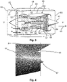
- Figure 3 shows a longitudinal section through a known, mixed-jets turbofan engine indicated generally by 50.
- Figure 4 shows a side view of a rear portion of the engine 50 with a pylon P fitted. Parts of the engine 50 are labelled using reference numerals differing by 40 from those labelling corresponding parts in Figures 1 and 2 .
- the engine 50 is similar to the engine 10 of Figures 1 to 3 except that it is a mixed-jets engine rather than a separate-jets engine.
- the outer fixed structure 61 of the engine 50 extends downstream of core exit plane 59 so that the engine core 64 does not have an afterbody.
- the outer fixed structure 61 terminates at its aft (downstream) end in a downstream terminal plane 63.
- Planes 59, 63 are each substantially normal to the longitudinal axis X of the engine 50.
- Bypass duct 62 terminates at the longitudinal position of core exit plane 59.
- bypass air exiting bypass duct 62 and exhaust from engine core 64 are mixed between planes 59 and 63 prior to being expelled through the downstream terminal plane 63 of the outer fixed structure 61.
- the outer fixed structure 61 has an intake 51 having an intake highlight 68.
- the outer wall 60 of the bypass duct 62, the core cowling 65 and centre-body 67 of the engine 10 are each axisymmetric, i.e. they each have circular cross-sections at all positions along the axis X at which they exist.
- the bypass duct outer wall 60 is circular at the downstream terminal plane 63 of the outer fixed structure 61 and at longitudinal positions fore (upstream) of the plane 23.
- the core cowling 65 is circular at core exit plane 59 and at longitudinal positions upstream of the core exit plane 59.
- a pylon P interrupts the outer fixed structure 61 over a limited angular range in azimuth around the axis X, however the pylon P does not extend through the downstream terminal plane 63 of the outer fixed structure 61.
- the internal surface of the outer fixed structure 61 therefore describes a closed path in the downstream terminal plane 63 thereof.
- turbofan engines to which the present disclosure may be applied may have alternative configurations.
- such engines may have an alternative number of interconnecting shafts (e.g. two) and/or an alternative number of compressors and/or turbines.
- an engine may comprise a gearbox provided in the drive train from a turbine to a compressor and/or fan.
- Figure 5 shows the internal surface 120 of the outer fixed structure of a first example turbofan engine, in the downstream terminal plane 123 of the outer fixed structure of the engine.
- the general direction of airflow through the engine is indicated at 169.
- the engine may be either a separate-jets engine or a mixed-jets engine; if it is a separate-jets engine then the plane 123 is also the bypass duct exit plane of the engine.
- Figure 6 shows a plot of the radius of the internal surface 120 versus azimuthal position ⁇ measured with respect to the longitudinal axis X of the engine and indicates four contiguous azimuthal intervals 1, 2, 3, 4 forming a combined interval of 360°.
- the radius R of the internal surface 120 of the outer fixed structure is a function of azimuthal position ⁇ , i.e.
- R R( ⁇ ).
- the radius R has a minimum value R 1 and a maximum value R 2 .
- the radius R is constant and equal to R 0 where R 2 > R 0 > R 1 , i.e. the internal surface 120 is circular in the interval 1, 90° ⁇ ⁇ ⁇ 270°, with radius R 0 .
- the internal surface 120 thus describes a closed path in the downstream terminal plane 123 of the outer fixed structure of the first example engine and is circular with radius R 0 in the first interval 90° ⁇ ⁇ ⁇ 270° but "flattened" in the third interval defined by 0° ⁇ ⁇ ⁇ ⁇ 1 and 360° - ⁇ 1 ⁇ ⁇ ⁇ 360° such that that R ⁇ R 0 .
- the radius R of the internal surface 120 is greater than R 0 over the second and fourth intervals 2, 4.
- Figures 5 and 6 indicate the radius R of the internal surface 120 as a function of azimuthal position ⁇ with respect to the axis X in the downstream terminal plane 123 of the outer fixed structure of the first example engine. Moving upstream of the terminal plane 123, the internal surface 120 of the outer fixed structure becomes increasingly axisymmetric (circular) until at a certain longitudinal position upstream of the terminal plane 123 the internal surface is substantially axisymmetric (circular).
- the relative values of the radii R 0 , R 1 and R 2 and of the angles ⁇ 1 , ⁇ 2 may differ from those indicated in Figure 5 and 6 .
- some or all of the values R 0 , R 1 ,R 2 , ⁇ 1 , ⁇ 2 may be selected so that the area enclosed by the internal surface 120 is approximately or substantially ⁇ R 0 2 .
- the internal surface 120 may have a discontinuity over a limited angular range for accommodating a pylon.
- Figure 7 shows the internal surface 220 of the outer fixed structure of a second example turbofan engine, in the downstream terminal plane 223 of the outer fixed structure of the engine.
- the second example turbofan engine is not an example of the invention but is nevertheless useful for understanding the invention.
- the general direction of airflow through the engine is indicated at 269.
- the engine may be either a separate-jets engine or a mixed-jets engine; if it is a separate-jets engine then the plane 223 is also the bypass duct exit plane of the engine.
- Figure 8 shows a plot of the radius of the internal surface 220 versus azimuthal position measured with respect to the longitudinal axis X of the engine and indicates three contiguous azimuthal intervals 1, 2, 3 forming a combined interval of 360°.
- the radius R has a minimum value R 1 and a maximum value R 2 .
- the radius R In the first interval 1, 0° ⁇ ⁇ ⁇ 270°, the radius R is constant and equal to R 0 , where R 2 > R 0 > R 1 ,i.e. the internal surface 220 is circular in the in the interval 0° ⁇ ⁇ ⁇ 270°.
- the internal surface 220 describes a closed path in the downstream terminal plane 223 of the outer fixed structure of the second example engine and is circular with radius R 0 in the first interval 1 and "flattened" (i.e. R ⁇ R 0 ) over the third interval 3.
- Figures 7 and 8 indicate the radius R of the internal surface 220 as a function of azimuthal position ⁇ with respect to the axis X in the downstream terminal plane 223 of the outer fixed structure of the second example engine.
- the internal surface 220 of the outer fixed structure Moving upstream of the terminal plane 223, the internal surface 220 of the outer fixed structure becomes increasingly axisymmetric (circular) until at a certain longitudinal position upstream of the terminal plane 223 the internal surface is substantially axisymmetric (circular).
- the relative values of R 0 , R 1 ,R 2 and the values ⁇ 1 , ⁇ 2 may differ from those represented in Figures 7 and 8 . In some variants some or all of these parameters may be selected such that the area enclosed by the internal surface 220 is approximately or substantially equal to ⁇ R 0 2 .
- the internal surface 220 may have a discontinuity over a limited angular range for accommodating a pylon.
- Figure 9 shows the internal surface 320 of the outer fixed structure of a third example turbofan engine, in the downstream terminal plane 323 of the outer fixed structure of the engine.
- the third example turbofan engine is not an example of the invention but is nevertheless useful for understanding the invention.
- the general direction of airflow through the engine is indicated at 369.
- the engine may be either a separate-jets engine or a mixed-jets engine; if it is a separate-jets engine then the plane 323 is also the bypass duct exit plane of the engine.
- Figure 10 shows a plot of the radius of the internal surface 320 versus azimuthal position ⁇ measured with respect to the longitudinal axis X of the engine and indicates three contiguous azimuthal intervals 1, 2, 3 forming a total or combined interval of 360°.
- the radius R has a minimum value R 1 and a maximum value R 2 .
- the radius R has a constant value R 0 the first azimuthal interval 1 ⁇ 1 ⁇ ⁇ ⁇ 270°, where R 2 > R 0 > R 1.
- the internal surface 320 thus describes a closed path in the downstream terminal plane 323 of the outer fixed structure of the third example engine and is circular with radius R 0 in the first interval 1 but "flattened"(i.e. R ⁇ R 0 ) in the third interval 3.
- R ⁇ R 0 radius of the internal surface 320 is greater than R 0 in the second interval 3
- Figures 9 and 10 indicate the radius R of the internal surface 320 as a function of azimuthal position ⁇ with respect to the axis X in the downstream terminal plane 323 of the outer fixed structure of the third example engine.
- the internal surface 320 of the outer fixed structure becomes increasingly axisymmetric (circular) until at a certain longitudinal position upstream of the terminal plane 123 the internal surface is substantially axisymmetric (circular).
- R R 0 over a first interval 90° ⁇ ⁇ ⁇ 360° - ⁇ 1
- the relative values of the radii R 0 , R 1 and R 2 and of the angles ⁇ 1 , ⁇ 2 may differ from those indicated in Figure 9 and 10 .
- some or all of the values R 0 , R 1 ,R 2 , ⁇ 1 , ⁇ 2 may be selected so that the area enclosed by the internal surface 320 is approximately or substantially ⁇ R 0 2 .
- the internal surface 320 may have a discontinuity over a limited angular range for accommodating a pylon.
- Figure 14 shows the internal surface 420 of the outer fixed structure of a fourth example turbofan engine, in the downstream terminal plane 423 of the outer fixed structure, the general direction of airflow through the engine being indicated at 469.
- Figure 15 shows a plot of the radius of the internal surface 420 of the outer fixed structure in the downstream terminal plane 423 of the structure as a function of azimuthal position ⁇ .
- the engine is a separate-jets turbofan engine so that the downstream terminal plane 423 of the outer fixed structure of the engine is also the bypass duct exit plane of the engine.
- the internal surface 423 is similar to the internal surface 123 of Figure 5 .
- Figure 15 indicates four azimuthal intervals, 1, 2, 3, 4 which are contiguous in azimuth ⁇ and correspond to a total interval of 360°.
- the radius of the internal surface 420 is constant and equal to R 0 .
- the internal surface 420 Upstream of the plane 423, the internal surface 420 becomes increasingly circular. At a certain position upstream of the plane 423 the internal surface is substantially circular (i.e. axisymmetric).
- Figure 16 shows the internal surface 520 of the outer fixed structure of a fifth example turbofan engine, in the downstream terminal plane 523 of the outer fixed structure, the general direction of airflow through the engine being indicated at 569.
- Figure 17 shows a plot of the radius of the internal surface 520 of the outer fixed structure in the downstream terminal plane 523 of the structure as a function of azimuthal position ⁇ .
- the engine is a separate-jets turbofan engine so that the downstream terminal plane 523 of the outer fixed structure of the engine is also the bypass duct exit plane of the engine.
- Figure 17 indicates four azimuthal intervals, 1, 2, 3, 4 which are contiguous in azimuth ⁇ and correspond to a total interval of 360°.
- the internal surface 420 Upstream of the plane 423, the internal surface 420 becomes increasingly circular. At a certain position upstream of the plane 423 the internal surface is substantially circular (i.e. axisymmetric).
- such an engine may have a fan of increased diameter compared to that of a conventional engine, providing lower specific thrust and greater specific fuel consumption than is the case for a turbofan engine with a smaller fan.
- the wetted area of the pylon in that plane is reduced compared to the case of a conventional engine, lowering drag on the bypass exhaust flow and improving engine performance.
- the downstream terminal plane of the outer fixed structure is flattened around the bottom of the structure.
- the speed of air in the region of the 'hump' of the core cowling around the bottom of the engine is reduced compared to the case of an engine having an outer fixed structure which is axisymmetric in its downstream terminal plane, reducing nozzle loss and improving nozzle performance compared to an axisymmetric engine.
- the total length of the outer fixed structure of such an engine may be shorter than that of an equivalent engine which is axisymmetric in its downstream terminal end plane, thus reducing weight and specific fuel consumption and allowing the engine to be mounted closer to a wing in the axial direction.
- the outer fixed structure may terminate at an axial position which depends on azimuthal position with respect to the longitudinal (rotation) axis of the engine.
- An example of an engine having such an outer fixed structure is the Rolls-Royce ® Trent ® 1000 which has chevrons.
- the downstream terminal plane of the outer fixed structure is that plane, normal to the axis of the engine, furthest downstream at which the internal surface of the outer fixed structure is unbroken in azimuth apart from one or more discontinuities such as that shown in Figures 14 and 16 suitable for accommodating an element such as a pylon.
- the internal and external radii at a given azimuthal position may be equal or substantially equal, or they may differ by a fixed amount which is independent of ⁇ .
Landscapes
- Engineering & Computer Science (AREA)
- Mechanical Engineering (AREA)
- General Engineering & Computer Science (AREA)
- Chemical & Material Sciences (AREA)
- Combustion & Propulsion (AREA)
- Structures Of Non-Positive Displacement Pumps (AREA)
Description
- Examples of turbofan engines are described.
- In a turbofan engine, an engine core bounded by a core cowling is positioned radially inwardly of outer fixed structure or nacelle with respect to the longitudinal axis of the engine, defining a bypass duct between the outer surface of the engine core's cowling and the internal surface of the outer fixed structure over an axial portion of the engine where both the core cowling and the outer fixed structure are present. Over this axial portion, the internal surface of the outer fixed structure provides an outer wall of the bypass duct and the core cowling provides the internal wall of the bypass duct. In the case of a separate-jets turbofan engine, the downstream terminal end of the outer fixed structure defines a bypass duct exit plane which is fore (upstream) of the exit plane of the engine core, both the bypass duct exit plane and the engine core exit plane being substantially normal to the longitudinal axis of the engine. In the case of a mixed-jets turbofan engine, the downstream terminal end of the outer fixed structure is located downstream of the engine core exit plane, both the engine core exit plane and the downstream terminal end of the outer fixed structure being substantially normal to the longitudinal axis of the engine.
- In operation of a separate-jets turbofan engine, exhaust from the engine core is expelled through the engine core exit plane. Bypass air passes through the bypass duct, and is expelled through the bypass duct exit plane as bypass exhaust flow which provides the majority of the engine's thrust. In the case of a mixed-jets engine, the bypass air and exhaust from the engine core are mixed in the region between the engine core exit plane and the downstream terminal end of the outer fixed structure.
- There is an ongoing desire to improve engine exhaust performance to reduce both specific fuel consumption and fuel burn.
- Published US patent application
US 2003/0146296 A1 discloses an outer structure of a gas turbine engine, the outer structure comprising an adaptable moving lip and having a downstream terminal end which in certain phases of flight has an internal surface of constant radius R over a first azimuthal interval greater than 180° with respect to the engine axis, and wherein the radius of the internal surface is alternately greater than and less than R over second to sixth azimuthal intervals, the first to sixth azimuthal intervals forming a total azimuthal interval of 360°. -
US patent 4280 587 discloses a discharge nozzle of a jet engine, the nozzle having lobes for promoting mixing of the jet engine discharge flow with ambient air to reduce jet noise. The radius of the internal surface of the nozzle in its downstream terminal plane, measured with respect to the engine axis, is multi-valued over certain azimuthal intervals defined with respect to the engine axis due to the presence of the lobes. - Published US patent application
US 2016/003194 A1 discloses a fan nozzle for a gas turbine engine, the internal radius of the nozzle in the downstream terminal plane thereof having a constant value R over a first azimuthal and a value which varies with azimuthal position but which is always greater than R over second and third azimuthal intervals each of which are contiguous with the first azimuthal interval but not with each other. The nozzle has a discontinuity between the second and third azimuthal intervals allowing accommodation of a supporting pylon. - According to the present invention, a turbofan engine comprises an engine core positioned radially inwardly of an outer fixed structure with respect to the longitudinal axis of the engine, the aft or downstream end of the outer fixed structure having a terminal plane which is substantially normal to the longitudinal axis of the engine, the radius R of the internal surface of the outer fixed structure in the terminal plane being a function R(φ) of azimuthal position φ in the terminal plane with respect to the longitudinal axis of the engine such that
- (i) the radius has a constant value R0 within a first azimuthal interval of at least 180°;
- (ii) the radius has a value greater than R0 at any azimuthal position within a second azimuthal interval; and
- (iii) the radius has a value less than R0 at any azimuthal position within a third azimuthal interval;
- (iv) the radius has a value greater than R0 at any azimuthal position within a fourth azimuthal interval;
- The internal surface may have a discontinuity over an azimuthal interval including the centre of the first azimuthal interval. The centre of the discontinuity may coincide in azimuth with the centre of the first azimuthal interval.
- The engine may be a separate-jets engine, the downstream terminal plane of the outer fixed structure being the bypass duct exit plane of the engine. Alternatively, the engine may be a mixed-jets engine.
- The internal and external radii of the outer fixed structure in the downstream terminal plane thereof may be substantially equal for all azimuthal positions where the outer fixed structure exists in the downstream terminal plane. Alternatively, the difference between the external and internal radii of the outer fixed structure in the downstream terminal plane thereof may be finite and constant for all azimuthal positions where the outer fixed structure exists in the downstream terminal plane.
- Examples are described below with reference to the accompanying drawings in which:
- Figure 1
- is a longitudinal section through a known, separate-jets, turbofan engine, the section including the longitudinal axis (rotation axis) of the engine;
- Figure 2
- is a side view of a rear portion of the
Figure 1 engine; - Figure 3
- is a longitudinal section through a known, mixed-jets, turbofan engine, the section including the longitudinal axis (rotation axis) of the engine;
- Figure 4
- is a side view of a rear portion of the
Figure 3 engine; - Figure 5
- shows the internal surface of the outer fixed structure of a first example turbofan engine in the downstream terminal plane of the structure;
- Figure 6
- shows a plot of the radius of the internal surface shown
Figure 5 as a function of azimuthal position; - Figure 7
- shows the internal surface of the outer fixed structure of a second example turbofan engine in the downstream terminal plane of the structure, the second example not being an example of the invention but nevertheless being useful for understanding the invention;
- Figure 8
- shows a plot of the radius of the internal surface shown in
Figure 7 as a function of azimuthal position; - Figure 9
- shows the internal surface of the outer fixed structure of a third example turbofan engine in the downstream terminal plane of the structure, the third example engine not being an example of the engine but nevertheless being useful for understanding the invention;
- Figure 10
- shows a plot of the radius of the internal surface shown in
Figure 9 as a function of azimuthal position; - Figure 11
- shows another plot of the radius of the internal surface shown in
Figure 5 as a function of azimuthal position; - Figure 12
- shows another plot of the radius of the internal surface shown in
Figure 7 as a function of azimuthal position; - Figure 13
- shows another plot of the radius of the internal surface shown in
Figure 9 as a function of azimuthal position; - Figure 14
- shows the internal surface of the outer fixed structure of a fourth example turbofan engine in the downstream terminal plane of the structure;
- Figure 15
- shows a plot the radius of the internal surface shown
Figure 14 as a function of azimuthal position; - Figure 16
- shows the internal surface of the outer fixed structure of a fifth example turbofan engine in the downstream terminal plane of the structure; and
- Figure 17
- shows a plot the radius of the internal surface shown
Figure 16 as a function of azimuthal position; - Referring to
Figures 1 and 2 , a known three-spool, separate-jets,turbofan engine 10 having a longitudinal (rotational) axis X comprises anengine core 24 having acore cowling 25 located radially inwardly of an outer fixedstructure 21 with respect to the axis X. The outer fixedstructure 21 terminates at its downstream end in adownstream terminal plane 23 which is substantially normal to the axis X. The portion of thecore cowling 25 fore of theterminal plane 23, and the internal surface of the outer fixedstructure 21 which longitudinally coincides with that portion respectively define inner 26 and outer 20 walls of abypass duct 22 which terminates at a bypass duct exit plane coincident with thedownstream terminal plane 23 of the outer fixedstructure 21. Theengine core 24 extends downstream of the bypassduct exit plane 23 so that theengine core 24 has an afterbody portion. Theengine core 24 terminates at acore exit plane 19 which is also substantially normal to the axis X. The outer fixedstructure 21 may not form complete annulus around the longitudinal axis X because it may be interrupted over a limited azimuthal range by a pylon (indicated by P inFigure 2 ) for attaching the engine to an aircraft, or by a space for accommodating such a pylon, depending on how theengine 10 is, or is to be, attached to an aircraft. Theengine 10 has apropulsive fan 12, intermediate 13 and high 14 pressure compressors,combustion equipment 15, and high 16, intermediate 17 and low 18 pressure turbines. A centre-body 27 extends through thecore exit plane 19. The outer fixedstructure 21 has anintake 11 having anintake highlight 28. - During operation of the
engine 10, air and combustion products pass through theengine 10 in a general direction indicated by 29. Air entering the outer fixedstructure 21 at the front of the engine is accelerated by thefan 12. Aft (downstream) of thefan 12 this air becomes divided into two air flows: a first air flow A into theintermediate pressure compressor 13 and a second air flow B which passes through thebypass duct 22. Theintermediate pressure compressor 13 compresses the air flow directed into it before delivering that air to thehigh pressure compressor 14 where further compression takes place. Air flow B is output from thebypass duct 22 at the bypassduct exit plane 23 and provides the majority of the engine's thrust. - Compressed air output from the high-
pressure compressor 14 is directed into thecombustion equipment 15 where it is mixed with fuel and the resulting mixture combusted. The resulting hot combustion products then expand through, and thereby drive the high, intermediate and low-pressure turbines exit plane 19 of theengine core 29 to provide further thrust. The high, intermediate andlow pressure turbines high pressure compressor 14,intermediate pressure compressor 13 andfan 12, each by means of a respective interconnecting shaft which has a rotation axis coincident with the longitudinal axis X of theengine 10. - In the
engine 10, theouter wall 20 of thebypass duct 22, thecore cowling 25 and the centre-body 27 of theengine 10 are each axisymmetric, i.e. they each have circular cross-sections at all positions along the axis X at which they exist. For example, the bypass ductouter wall 20 is circular at the bypassduct exit plane 23 and at longitudinal positions fore (upstream) of the bypassduct exit plane 23. Thecore cowling 25 is circular at thecore exit plane 19 and at longitudinal positions upstream of thecore exit plane 19. As shown inFigure 2 , a pylon P may interrupt the outer fixedstructure 21 over a limited angular range in azimuth around the axis X. The pylon P extends through the bypassduct exit plane 23 so that the bypass duct outer wall 20 (equivalently the internal surface of the outer fixed structure 21) does not describe a closed path in the bypass duct exit 23 (equivalently the downstream terminal plane of the outer fixed structure 21). -
Figure 3 shows a longitudinal section through a known, mixed-jets turbofan engine indicated generally by 50.Figure 4 shows a side view of a rear portion of theengine 50 with a pylon P fitted. Parts of theengine 50 are labelled using reference numerals differing by 40 from those labelling corresponding parts inFigures 1 and 2 . Theengine 50 is similar to theengine 10 ofFigures 1 to 3 except that it is a mixed-jets engine rather than a separate-jets engine. The outer fixedstructure 61 of theengine 50 extends downstream ofcore exit plane 59 so that theengine core 64 does not have an afterbody. The outer fixedstructure 61 terminates at its aft (downstream) end in adownstream terminal plane 63.Planes engine 50.Bypass duct 62 terminates at the longitudinal position ofcore exit plane 59. During operation of theengine 50, bypass air exitingbypass duct 62 and exhaust fromengine core 64 are mixed betweenplanes downstream terminal plane 63 of the outer fixedstructure 61. The outer fixedstructure 61 has anintake 51 having anintake highlight 68. - In the
engine 50, theouter wall 60 of thebypass duct 62, thecore cowling 65 and centre-body 67 of theengine 10 are each axisymmetric, i.e. they each have circular cross-sections at all positions along the axis X at which they exist. For example, the bypass ductouter wall 60 is circular at thedownstream terminal plane 63 of the outer fixedstructure 61 and at longitudinal positions fore (upstream) of theplane 23. Thecore cowling 65 is circular atcore exit plane 59 and at longitudinal positions upstream of thecore exit plane 59. InFigure 4 , a pylon P interrupts the outer fixedstructure 61 over a limited angular range in azimuth around the axis X, however the pylon P does not extend through thedownstream terminal plane 63 of the outer fixedstructure 61. The internal surface of the outer fixedstructure 61 therefore describes a closed path in thedownstream terminal plane 63 thereof. - Other turbofan engines to which the present disclosure may be applied may have alternative configurations. For example, such engines may have an alternative number of interconnecting shafts (e.g. two) and/or an alternative number of compressors and/or turbines. Further, an engine may comprise a gearbox provided in the drive train from a turbine to a compressor and/or fan.
-
Figure 5 shows theinternal surface 120 of the outer fixed structure of a first example turbofan engine, in the downstreamterminal plane 123 of the outer fixed structure of the engine. The general direction of airflow through the engine is indicated at 169. The engine may be either a separate-jets engine or a mixed-jets engine; if it is a separate-jets engine then theplane 123 is also the bypass duct exit plane of the engine.Figure 6 shows a plot of the radius of theinternal surface 120 versus azimuthal position φ measured with respect to the longitudinal axis X of the engine and indicates four contiguousazimuthal intervals internal surface 120 of the outer fixed structure is a function of azimuthal position φ, i.e. R = R(φ). The radius R has a minimum value R1 and a maximum value R2. In thefirst interval 1, 90° ≤ φ ≤ 270°, the radius R is constant and equal to R0 where R2 > R0 > R1, i.e. theinternal surface 120 is circular in theinterval 1, 90° ≤ φ ≤ 270°, with radius R0. In thesecond interval 2, 270° < φ < 360° - φ1 the radius R is greater than R0 and passes through the maximum value R2 at φ = 360° - φ2. Over thethird interval 3, defined by 360° - φ1 < φ < 360° and 0° ≤ φ < φ1 the radius R is less than R0 and passes through the minimum value R1 at φ = 0°. Over thefourth interval 4 φ1 < φ < 90° the radius R is greater than R0 and passes through the maximum value R2 at φ = φ2. Over intervals where the radius R increases or decreases, it does so monotonically with φ. P(φ1) = P(360°-φ1) = R0. - The
internal surface 120 thus describes a closed path in the downstreamterminal plane 123 of the outer fixed structure of the first example engine and is circular with radius R0 in the first interval 90° ≤ φ ≤ 270° but "flattened" in the third interval defined by 0° ≤ φ < φ1 and 360° - φ1 < φ < 360° such that that R < R0. On the other hand the radius R of theinternal surface 120 is greater than R0 over the second andfourth intervals -
Figures 5 and 6 indicate the radius R of theinternal surface 120 as a function of azimuthal position φ with respect to the axis X in the downstreamterminal plane 123 of the outer fixed structure of the first example engine. Moving upstream of theterminal plane 123, theinternal surface 120 of the outer fixed structure becomes increasingly axisymmetric (circular) until at a certain longitudinal position upstream of theterminal plane 123 the internal surface is substantially axisymmetric (circular). - In variants of the first example engine, the relative values of the radii R0, R1 and R2 and of the angles φ1, φ2 may differ from those indicated in
Figure 5 and 6 . In some variants, in the interval 270° < φ < 360°, the azimuthal positions at which the radius R has the values R2 and R0 may be 360° - φ3 and 360° - φ4 respectively where 90° > φ3 > φ4 and φ3 ≠ φ2, φ4 ≠ φ1 so that theinternal surface 120 is not symmetric about a plane containing the axis X and defined by the φ = 0°, 180° positions. In some variants, some or all of the values R0, R1,R2, φ1, φ2 (and also φ3, φ4 as appropriate) may be selected so that the area enclosed by theinternal surface 120 is approximately or substantially πR0 2. - If the first example engine is a separate-jets engine, the
internal surface 120 may have a discontinuity over a limited angular range for accommodating a pylon. The discontinuity could have any azimuthal position for example it could include the positions φ = 0° or φ = 180° and may be either symmetrical or asymmetrical with respect to those positions. The azimuthal orientation of the engine when installed on air aircraft may vary. For example, φ = 0° may correspond to the vertically upward direction and φ = 180° to the vertically downward direction or vice-versa. -
Figure 7 shows theinternal surface 220 of the outer fixed structure of a second example turbofan engine, in the downstreamterminal plane 223 of the outer fixed structure of the engine. The second example turbofan engine is not an example of the invention but is nevertheless useful for understanding the invention. The general direction of airflow through the engine is indicated at 269. The engine may be either a separate-jets engine or a mixed-jets engine; if it is a separate-jets engine then theplane 223 is also the bypass duct exit plane of the engine.Figure 8 shows a plot of the radius of theinternal surface 220 versus azimuthal position measured with respect to the longitudinal axis X of the engine and indicates three contiguousazimuthal intervals - The radius R of the
internal surface 220 of the outer fixed structure is a function of azimuthal position φ with respect to the axis X, i.e. R = R(φ). The radius R has a minimum value R1 and a maximum value R2. In thefirst interval internal surface 220 is circular in the in theinterval 0° ≤ φ ≤ 270°. In thesecond interval 2, 270° < φ < 360° - φ1 the radius R is greater than R0 and passes through the maximum value R2 at φ = 360° - φ2. Over thethird interval - At φ = 0° or 360°, the
internal surface 220 has aportion 230 which extends directly radially outward from R = R1 to R = R0. Theinternal surface 220 describes a closed path in the downstreamterminal plane 223 of the outer fixed structure of the second example engine and is circular with radius R0 in thefirst interval 1 and "flattened" (i.e. R < R0) over thethird interval 3. On the other hand the radius R of theinternal surface 220 is greater than R0 in thesecond interval 2 and reaches the maximum value R2 at φ = 360° - φ2. -
Figures 7 and 8 indicate the radius R of theinternal surface 220 as a function of azimuthal position φ with respect to the axis X in the downstreamterminal plane 223 of the outer fixed structure of the second example engine. Moving upstream of theterminal plane 223, theinternal surface 220 of the outer fixed structure becomes increasingly axisymmetric (circular) until at a certain longitudinal position upstream of theterminal plane 223 the internal surface is substantially axisymmetric (circular). - In variants of the second example engine, the relative values of R0, R1,R2 and the values φ1, φ2 may differ from those represented in
Figures 7 and 8 . In some variants some or all of these parameters may be selected such that the area enclosed by theinternal surface 220 is approximately or substantially equal to πR0 2. In some variants of the second example engine the function R(φ) may be such that form of the internal surface is laterally inverted about the φ = 0°, 180° position compared to thesurface 220 ofFigure 7 so that the R = R0 over an interval 90° ≤ φ ≤ 360°, R monotonically increases from R1 to R2 over aninterval 0 < φ < φ2, and R monotonically decreases from R2 to R0 over an interval φ2 < φ < 90° where R(φ1) = R0, R(φ2) = R2 and 90° > φ2 > φ1. - If the second example engine is a separate-jets engine, the
internal surface 220 may have a discontinuity over a limited angular range for accommodating a pylon. The discontinuity could have any azimuthal position for example it could include the positions φ = 0° or φ = 180° and may be either symmetrical or asymmetrical with respect to those positions. The azimuthal orientation of the engine when installed on air aircraft may vary. For example, φ = 0° may correspond to the vertically upward direction and φ = 180° to the vertically downward direction or vice-versa. -
Figure 9 shows theinternal surface 320 of the outer fixed structure of a third example turbofan engine, in the downstreamterminal plane 323 of the outer fixed structure of the engine. The third example turbofan engine is not an example of the invention but is nevertheless useful for understanding the invention. The general direction of airflow through the engine is indicated at 369. The engine may be either a separate-jets engine or a mixed-jets engine; if it is a separate-jets engine then theplane 323 is also the bypass duct exit plane of the engine.Figure 10 shows a plot of the radius of theinternal surface 320 versus azimuthal position φ measured with respect to the longitudinal axis X of the engine and indicates three contiguousazimuthal intervals internal surface 320 of the outer fixed structure is a function of azimuthal position φ with respect to the axis X, i.e. R = R(φ). The radius R has a minimum value R1 and a maximum value R2. The radius R has a constant value R0 the firstazimuthal interval 1 φ1 ≤ φ ≤ 270°, where R2 > R0 > R1. In the secondazimuthal interval 2, 270° < φ ≤ 360° - φ1, the radius R is greater than R0 and reaches the maximum value R2 at φ = 360 - φ2. Over the thirdazimuthal interval 3, defined by 360° - φ1 < φ < 360° and 0° ≤ φ < φ1 the radius R is less than R0 and passes through the minimum value R1 at φ = 0°. Over intervals where the radius increases or decreases, it does so monotonically. P(360°-φ1) = R0. - The
internal surface 320 thus describes a closed path in the downstreamterminal plane 323 of the outer fixed structure of the third example engine and is circular with radius R0 in thefirst interval 1 but "flattened"(i.e. R < R0) in thethird interval 3. On the other hand the radius R of theinternal surface 320 is greater than R0 in thesecond interval 3 -
Figures 9 and 10 indicate the radius R of theinternal surface 320 as a function of azimuthal position φ with respect to the axis X in the downstreamterminal plane 323 of the outer fixed structure of the third example engine. Moving upstream of theterminal plane 323, theinternal surface 320 of the outer fixed structure becomes increasingly axisymmetric (circular) until at a certain longitudinal position upstream of theterminal plane 123 the internal surface is substantially axisymmetric (circular). - In variants of the third example engine, the relative values of R0, R1, R2 and the values φ 1, φ2 may differ from those represented in
Figures 9 and 10 . In some variants some or all of these parameters may be selected such that the area enclosed by theinternal surface 320 is approximately or substantially equal to πR0 2. In some variants of the third example engine the function R(φ) may be such that the form of the internal surface is laterally inverted about the φ = 0°, 180° position compared to thesurface 320 ofFigure 9 . In this case R = R0 over a first interval 90° ≤ φ ≤ 360° - φ1, R < R0 over an interval defined by 360° - φ1 < φ ≤ 360° and 0° < φ < φ1 and R > R0 over a third interval φ1 < φ < 90° and where R (φ1) =R0, R(φ2) = R2. - In variants of the third example engine, the relative values of the radii R0, R1 and R2 and of the angles φ1, φ2 may differ from those indicated in
Figure 9 and 10 . In some variants, some or all of the values R0, R1,R2, φ1, φ2 may be selected so that the area enclosed by theinternal surface 320 is approximately or substantially πR0 2. - If the second example engine is a separate-jets engine, the
internal surface 320 may have a discontinuity over a limited angular range for accommodating a pylon. The discontinuity could have any azimuthal position for example it could include either of positions φ = 0° or φ = 180° and may be either symmetrical or asymmetrical with respect to either position. The azimuthal orientation of the engine when installed on air aircraft may vary. For example, φ = 0° may correspond to the vertically upward direction and φ = 180° to the vertically downward direction or vice-versa. -
Figures 11, 12 and 13 are plots of radius R against φ equivalent to theFigures 6 ,8 and10 respectively but with the first azimuthal interval (over which R = R0) represented on the left-hand side of the plot in each case. -
Figure 14 shows theinternal surface 420 of the outer fixed structure of a fourth example turbofan engine, in the downstreamterminal plane 423 of the outer fixed structure, the general direction of airflow through the engine being indicated at 469.Figure 15 shows a plot of the radius of theinternal surface 420 of the outer fixed structure in the downstreamterminal plane 423 of the structure as a function of azimuthal position φ. The engine is a separate-jets turbofan engine so that the downstreamterminal plane 423 of the outer fixed structure of the engine is also the bypass duct exit plane of the engine. The outer fixed structure has a discontinuity which extends through the bypassduct exit plane 423 such that theinternal surface 420 has a discontinuity of total angular extent α + β in the bypassduct exit plane 423 which includes the position φ = 0°. However the angular extent of the discontinuity is asymmetric about φ = 0°, i.e. α ≠ β, Ra ≈ Rb, and Ra, Rb > R1 (R1 is the radius of the complete geometric path corresponding to the internal surface 420). Apart from the discontinuity, theinternal surface 423 is similar to theinternal surface 123 ofFigure 5 .Figure 15 indicates four azimuthal intervals, 1, 2, 3, 4 which are contiguous in azimuth φ and correspond to a total interval of 360°. In thefirst interval 1 90° ≤ φ ≤ 270° the radius of theinternal surface 420 is constant and equal to R0. In thesecond interval 2 the radius R passes through a maximum value R2 at 360° - φ2 and returns to the value R0 at φ = 360° - φ1. In thethird interval 3 the radius of theinternal surface 420 reduces to a value Rb at φ = 360° - β which is slightly greater than a minimum value R(0°) = R1 of the complete geometric path corresponding to theinternal surface 420 and there is a first portion of the discontinuity in therange 360° - β < φ ≤ 360° and a second portion of the discontinuity in therange 0° < φ < α (α ≠ β). The radius increases from Ra ≈ R1 to R0 at φ = φ1. In thefourth interval 4 the radius passes through the maximum value R2 at φ = φ2 and then reduces to R0 at φ = 90°. Over intervals where the radius increases or decreases, it does so monotonically with φ. - Upstream of the
plane 423, theinternal surface 420 becomes increasingly circular. At a certain position upstream of theplane 423 the internal surface is substantially circular (i.e. axisymmetric). - In variants of the fourth example engine, the discontinuity in the internal surface of the outer fixed structure in the bypass duct exit is symmetric about the position φ = 0°, i.e. α = β.
-
Figure 16 shows theinternal surface 520 of the outer fixed structure of a fifth example turbofan engine, in the downstreamterminal plane 523 of the outer fixed structure, the general direction of airflow through the engine being indicated at 569.Figure 17 shows a plot of the radius of theinternal surface 520 of the outer fixed structure in the downstreamterminal plane 523 of the structure as a function of azimuthal position φ. The engine is a separate-jets turbofan engine so that the downstreamterminal plane 523 of the outer fixed structure of the engine is also the bypass duct exit plane of the engine. The outer fixed structure has a discontinuity which extends through the bypassduct exit plane 523 such that theinternal surface 520 in the bypassduct exit plane 423 has a discontinuity of total angular extent α + β which includes the position φ = 0°. The angular extent of the discontinuity is asymmetric about φ = 0°, i.e. α ≠ β. -
Figure 17 indicates four azimuthal intervals, 1, 2, 3, 4 which are contiguous in azimuth φ and correspond to a total interval of 360°. Theinternal surface 520 is circular (R = R0) over a firstazimuthal interval 1 defined by α ≤ φ ≤ 90° and 270° ≤ φ ≤360° - β. In the azimuthal intervals 90° < φ < φ1 and 360° - φ1 < φ < 270° the radius R > R0 and passes through a maximum value R2 at φ = φ2 and φ = 360° - φ2 respectively. In the interval φ1 < φ < 360° - φ1 the radius R is less than R0 and passes through a minimum value R1at φ = 180°. On either side of the discontinuity, the radius of theinternal surface 520 is R0, i.e. R(α) = R(360° - β) = R0. Over intervals where the radius increases or decreases, it does so monotonically with φ. - Upstream of the
plane 423, theinternal surface 420 becomes increasingly circular. At a certain position upstream of theplane 423 the internal surface is substantially circular (i.e. axisymmetric). - In variants of the fifth example engine, the discontinuity in the internal surface of the outer fixed surface in the bypass duct exit is symmetric about the position φ = 0° , i.e. α = β.
- Referring again to the first, second and third example engines and to
Figures 5 to 13 , theinternal surfaces - If the third azimuthal interval of any of the engines of
Figures 5 ,7 , and9 includes the vertically downward direction when the engine is installed on an aircraft then the downstream terminal plane of the outer fixed structure is flattened around the bottom of the structure. In operation of such an engine, the speed of air in the region of the 'hump' of the core cowling around the bottom of the engine is reduced compared to the case of an engine having an outer fixed structure which is axisymmetric in its downstream terminal plane, reducing nozzle loss and improving nozzle performance compared to an axisymmetric engine. Additionally, the total length of the outer fixed structure of such an engine may be shorter than that of an equivalent engine which is axisymmetric in its downstream terminal end plane, thus reducing weight and specific fuel consumption and allowing the engine to be mounted closer to a wing in the axial direction. - In other examples engines, the outer fixed structure may terminate at an axial position which depends on azimuthal position with respect to the longitudinal (rotation) axis of the engine. An example of an engine having such an outer fixed structure is the Rolls-Royce® Trent® 1000 which has chevrons. In such an example, for the purposes of the present disclosure, the downstream terminal plane of the outer fixed structure is that plane, normal to the axis of the engine, furthest downstream at which the internal surface of the outer fixed structure is unbroken in azimuth apart from one or more discontinuities such as that shown in
Figures 14 and16 suitable for accommodating an element such as a pylon. - In the downstream terminal plane of an outer fixed structure of an engine, the internal and external radii at a given azimuthal position may be equal or substantially equal, or they may differ by a fixed amount which is independent of φ.
- Various modifications and improvements can be made to the examples described above without departing from the concepts described herein. The invention is defined by the appended set of claims.
Claims (8)
- A turbofan engine comprising an engine core positioned radially inwardly of an outer fixed structure with respect to the longitudinal axis of the engine, the aft or downstream end of the outer fixed structure having a terminal plane (123; 223; 323; 423; 523) which is substantially normal to the longitudinal axis (X) of the engine, the radius R of the internal surface (120; 220; 320; 420; 520) of the outer fixed structure in the terminal plane being a function R(φ) of azimuthal position φ in the terminal plane with respect to the longitudinal axis of the engine such that(i) the radius has a constant value R0 within a first azimuthal interval (1) of at least 180°;(ii) the radius has a value greater than R0 at any azimuthal position within a second azimuthal interval (2); and(iii) the radius has a value less than R0 at any azimuthal position within a third azimuthal interval (3);(iv) the radius has a value greater than R0 at any azimuthal position within a fourth azimuthal interval (4);
wherein the second azimuthal interval is contiguous with the first and third azimuthal intervals, the fourth azimuthal interval is contiguous with the first and third azimuthal intervals, the first, second, third and fourth azimuthal intervals form a total azimuthal interval of 360°, and characterised in that R(φ) is single-valued at all azimuthal positions φ at which the internal surface of the outer fixed structure exists in the terminal plane. - A turbofan engine according to claim 1 wherein the radius passes through a maximum value R2 at a single azimuthal position within each of the second and fourth azimuthal intervals and passes through a minimum value R1at a single azimuthal position within the third azimuthal interval, wherein R2 > R0 > R1 and wherein the radius is a monotonic function of azimuthal position φ between any pair of azimuthal positions corresponding to (a) a maximum and a minimum value of the radius and (b) a maximum value of the radius and an adjacent boundary which is either the boundary of the first and second azimuthal intervals or the boundary of the first and fourth azimuthal intervals.
- A turbofan engine according to claim 2 wherein the radius of the internal surface (120) has the maximum value R2 at the midpoints of the second and fourth azimuthal intervals.
- A turbofan engine according to claim 2 or claim 3 wherein the minimum value R1 of the radius of the internal surface (120) occurs at the midpoint of the third azimuthal interval.
- A turbofan engine according to claim 4 wherein the internal surface has a discontinuity over an azimuthal interval which includes the azimuthal position corresponding to the minimum value R1.
- A turbofan engine according to claim 5 wherein the centre of the discontinuity coincides in azimuth with the azimuthal position corresponding to the minimum value R1.
- A turbofan engine according to claim 1 wherein the internal surface (520) has a discontinuity over an azimuthal interval including the centre of the first azimuthal interval.
- A turbofan engine according to claim 7 wherein the centre of the discontinuity coincides in azimuth with the centre of the first azimuthal interval.
Applications Claiming Priority (1)
| Application Number | Priority Date | Filing Date | Title |
|---|---|---|---|
| GBGB1806426.1A GB201806426D0 (en) | 2018-04-20 | 2018-04-20 | Turbofan engine |
Publications (2)
| Publication Number | Publication Date |
|---|---|
| EP3557035A1 EP3557035A1 (en) | 2019-10-23 |
| EP3557035B1 true EP3557035B1 (en) | 2022-05-11 |
Family
ID=62236260
Family Applications (1)
| Application Number | Title | Priority Date | Filing Date |
|---|---|---|---|
| EP19163951.7A Active EP3557035B1 (en) | 2018-04-20 | 2019-03-20 | Turbofan engine |
Country Status (3)
| Country | Link |
|---|---|
| US (1) | US20190323452A1 (en) |
| EP (1) | EP3557035B1 (en) |
| GB (1) | GB201806426D0 (en) |
Families Citing this family (1)
| Publication number | Priority date | Publication date | Assignee | Title |
|---|---|---|---|---|
| US10839265B2 (en) * | 2018-11-12 | 2020-11-17 | Sap Se | Platform for preventing adversarial attacks on image-based machine learning models |
Family Cites Families (5)
| Publication number | Priority date | Publication date | Assignee | Title |
|---|---|---|---|---|
| US4280587A (en) * | 1979-05-08 | 1981-07-28 | The Boeing Company | Noise-suppressing jet engine nozzles and method |
| US6705547B2 (en) * | 2002-02-01 | 2004-03-16 | Luis Manuel Braga Da Costa Campos | Active noise reducing nozzle |
| US9057286B2 (en) * | 2010-03-30 | 2015-06-16 | United Technologies Corporation | Non-circular aft nacelle cowling geometry |
| EP2971727B1 (en) * | 2013-03-15 | 2018-04-11 | United Technologies Corporation | Asymmetric fan nozzle in high-bpr separate-flow nacelle |
| PL415184A1 (en) * | 2015-12-10 | 2017-06-19 | General Electric Company | Exhaust nozzle for the engine with gas turbine |
-
2018
- 2018-04-20 GB GBGB1806426.1A patent/GB201806426D0/en not_active Ceased
-
2019
- 2019-03-20 EP EP19163951.7A patent/EP3557035B1/en active Active
- 2019-03-21 US US16/360,606 patent/US20190323452A1/en not_active Abandoned
Also Published As
| Publication number | Publication date |
|---|---|
| GB201806426D0 (en) | 2018-06-06 |
| US20190323452A1 (en) | 2019-10-24 |
| EP3557035A1 (en) | 2019-10-23 |
Similar Documents
| Publication | Publication Date | Title |
|---|---|---|
| US20230025200A1 (en) | Gas turbine engine inlet | |
| EP3187712B1 (en) | Nacelle short inlet | |
| US11391216B2 (en) | Elongated geared turbofan with high bypass ratio | |
| US20130343892A1 (en) | Propfan engine | |
| US10550704B2 (en) | High performance convergent divergent nozzle | |
| GB2562433A (en) | An airplane | |
| EP2963276B1 (en) | Compact nacelle with contoured fan nozzle | |
| US20160017715A1 (en) | Fan exit guide vane platform contouring | |
| EP3557035B1 (en) | Turbofan engine | |
| EP3473841B1 (en) | Turbofan engine | |
| EP3181862B1 (en) | Gas turbine engine with rotating inlet | |
| GB2575232A (en) | Turbofan engine | |
| US11920539B1 (en) | Gas turbine exhaust nozzle noise abatement | |
| EP3181863A1 (en) | Gas turbine engine with minimized inlet distortion | |
| US10731661B2 (en) | Gas turbine engine with short inlet and blade removal feature |
Legal Events
| Date | Code | Title | Description |
|---|---|---|---|
| PUAI | Public reference made under article 153(3) epc to a published international application that has entered the european phase |
Free format text: ORIGINAL CODE: 0009012 |
|
| STAA | Information on the status of an ep patent application or granted ep patent |
Free format text: STATUS: THE APPLICATION HAS BEEN PUBLISHED |
|
| AK | Designated contracting states |
Kind code of ref document: A1 Designated state(s): AL AT BE BG CH CY CZ DE DK EE ES FI FR GB GR HR HU IE IS IT LI LT LU LV MC MK MT NL NO PL PT RO RS SE SI SK SM TR |
|
| AX | Request for extension of the european patent |
Extension state: BA ME |
|
| RAP1 | Party data changed (applicant data changed or rights of an application transferred) |
Owner name: ROLLS-ROYCE PLC |
|
| STAA | Information on the status of an ep patent application or granted ep patent |
Free format text: STATUS: REQUEST FOR EXAMINATION WAS MADE |
|
| 17P | Request for examination filed |
Effective date: 20200313 |
|
| RBV | Designated contracting states (corrected) |
Designated state(s): AL AT BE BG CH CY CZ DE DK EE ES FI FR GB GR HR HU IE IS IT LI LT LU LV MC MK MT NL NO PL PT RO RS SE SI SK SM TR |
|
| GRAP | Despatch of communication of intention to grant a patent |
Free format text: ORIGINAL CODE: EPIDOSNIGR1 |
|
| STAA | Information on the status of an ep patent application or granted ep patent |
Free format text: STATUS: GRANT OF PATENT IS INTENDED |
|
| GRAS | Grant fee paid |
Free format text: ORIGINAL CODE: EPIDOSNIGR3 |
|
| GRAA | (expected) grant |
Free format text: ORIGINAL CODE: 0009210 |
|
| STAA | Information on the status of an ep patent application or granted ep patent |
Free format text: STATUS: THE PATENT HAS BEEN GRANTED |
|
| INTG | Intention to grant announced |
Effective date: 20220321 |
|
| AK | Designated contracting states |
Kind code of ref document: B1 Designated state(s): AL AT BE BG CH CY CZ DE DK EE ES FI FR GB GR HR HU IE IS IT LI LT LU LV MC MK MT NL NO PL PT RO RS SE SI SK SM TR |
|
| REG | Reference to a national code |
Ref country code: GB Ref legal event code: FG4D |
|
| REG | Reference to a national code |
Ref country code: CH Ref legal event code: EP |
|
| REG | Reference to a national code |
Ref country code: AT Ref legal event code: REF Ref document number: 1491586 Country of ref document: AT Kind code of ref document: T Effective date: 20220515 |
|
| REG | Reference to a national code |
Ref country code: DE Ref legal event code: R096 Ref document number: 602019014727 Country of ref document: DE |
|
| REG | Reference to a national code |
Ref country code: IE Ref legal event code: FG4D |
|
| REG | Reference to a national code |
Ref country code: LT Ref legal event code: MG9D |
|
| REG | Reference to a national code |
Ref country code: NL Ref legal event code: MP Effective date: 20220511 |
|
| REG | Reference to a national code |
Ref country code: AT Ref legal event code: MK05 Ref document number: 1491586 Country of ref document: AT Kind code of ref document: T Effective date: 20220511 |
|
| PG25 | Lapsed in a contracting state [announced via postgrant information from national office to epo] |
Ref country code: SE Free format text: LAPSE BECAUSE OF FAILURE TO SUBMIT A TRANSLATION OF THE DESCRIPTION OR TO PAY THE FEE WITHIN THE PRESCRIBED TIME-LIMIT Effective date: 20220511 Ref country code: PT Free format text: LAPSE BECAUSE OF FAILURE TO SUBMIT A TRANSLATION OF THE DESCRIPTION OR TO PAY THE FEE WITHIN THE PRESCRIBED TIME-LIMIT Effective date: 20220912 Ref country code: NO Free format text: LAPSE BECAUSE OF FAILURE TO SUBMIT A TRANSLATION OF THE DESCRIPTION OR TO PAY THE FEE WITHIN THE PRESCRIBED TIME-LIMIT Effective date: 20220811 Ref country code: NL Free format text: LAPSE BECAUSE OF FAILURE TO SUBMIT A TRANSLATION OF THE DESCRIPTION OR TO PAY THE FEE WITHIN THE PRESCRIBED TIME-LIMIT Effective date: 20220511 Ref country code: LT Free format text: LAPSE BECAUSE OF FAILURE TO SUBMIT A TRANSLATION OF THE DESCRIPTION OR TO PAY THE FEE WITHIN THE PRESCRIBED TIME-LIMIT Effective date: 20220511 Ref country code: HR Free format text: LAPSE BECAUSE OF FAILURE TO SUBMIT A TRANSLATION OF THE DESCRIPTION OR TO PAY THE FEE WITHIN THE PRESCRIBED TIME-LIMIT Effective date: 20220511 Ref country code: GR Free format text: LAPSE BECAUSE OF FAILURE TO SUBMIT A TRANSLATION OF THE DESCRIPTION OR TO PAY THE FEE WITHIN THE PRESCRIBED TIME-LIMIT Effective date: 20220812 Ref country code: FI Free format text: LAPSE BECAUSE OF FAILURE TO SUBMIT A TRANSLATION OF THE DESCRIPTION OR TO PAY THE FEE WITHIN THE PRESCRIBED TIME-LIMIT Effective date: 20220511 Ref country code: ES Free format text: LAPSE BECAUSE OF FAILURE TO SUBMIT A TRANSLATION OF THE DESCRIPTION OR TO PAY THE FEE WITHIN THE PRESCRIBED TIME-LIMIT Effective date: 20220511 Ref country code: BG Free format text: LAPSE BECAUSE OF FAILURE TO SUBMIT A TRANSLATION OF THE DESCRIPTION OR TO PAY THE FEE WITHIN THE PRESCRIBED TIME-LIMIT Effective date: 20220811 Ref country code: AT Free format text: LAPSE BECAUSE OF FAILURE TO SUBMIT A TRANSLATION OF THE DESCRIPTION OR TO PAY THE FEE WITHIN THE PRESCRIBED TIME-LIMIT Effective date: 20220511 |
|
| PG25 | Lapsed in a contracting state [announced via postgrant information from national office to epo] |
Ref country code: RS Free format text: LAPSE BECAUSE OF FAILURE TO SUBMIT A TRANSLATION OF THE DESCRIPTION OR TO PAY THE FEE WITHIN THE PRESCRIBED TIME-LIMIT Effective date: 20220511 Ref country code: PL Free format text: LAPSE BECAUSE OF FAILURE TO SUBMIT A TRANSLATION OF THE DESCRIPTION OR TO PAY THE FEE WITHIN THE PRESCRIBED TIME-LIMIT Effective date: 20220511 Ref country code: LV Free format text: LAPSE BECAUSE OF FAILURE TO SUBMIT A TRANSLATION OF THE DESCRIPTION OR TO PAY THE FEE WITHIN THE PRESCRIBED TIME-LIMIT Effective date: 20220511 Ref country code: IS Free format text: LAPSE BECAUSE OF FAILURE TO SUBMIT A TRANSLATION OF THE DESCRIPTION OR TO PAY THE FEE WITHIN THE PRESCRIBED TIME-LIMIT Effective date: 20220911 |
|
| PG25 | Lapsed in a contracting state [announced via postgrant information from national office to epo] |
Ref country code: SM Free format text: LAPSE BECAUSE OF FAILURE TO SUBMIT A TRANSLATION OF THE DESCRIPTION OR TO PAY THE FEE WITHIN THE PRESCRIBED TIME-LIMIT Effective date: 20220511 Ref country code: SK Free format text: LAPSE BECAUSE OF FAILURE TO SUBMIT A TRANSLATION OF THE DESCRIPTION OR TO PAY THE FEE WITHIN THE PRESCRIBED TIME-LIMIT Effective date: 20220511 Ref country code: RO Free format text: LAPSE BECAUSE OF FAILURE TO SUBMIT A TRANSLATION OF THE DESCRIPTION OR TO PAY THE FEE WITHIN THE PRESCRIBED TIME-LIMIT Effective date: 20220511 Ref country code: EE Free format text: LAPSE BECAUSE OF FAILURE TO SUBMIT A TRANSLATION OF THE DESCRIPTION OR TO PAY THE FEE WITHIN THE PRESCRIBED TIME-LIMIT Effective date: 20220511 Ref country code: DK Free format text: LAPSE BECAUSE OF FAILURE TO SUBMIT A TRANSLATION OF THE DESCRIPTION OR TO PAY THE FEE WITHIN THE PRESCRIBED TIME-LIMIT Effective date: 20220511 Ref country code: CZ Free format text: LAPSE BECAUSE OF FAILURE TO SUBMIT A TRANSLATION OF THE DESCRIPTION OR TO PAY THE FEE WITHIN THE PRESCRIBED TIME-LIMIT Effective date: 20220511 |
|
| REG | Reference to a national code |
Ref country code: DE Ref legal event code: R097 Ref document number: 602019014727 Country of ref document: DE |
|
| PLBE | No opposition filed within time limit |
Free format text: ORIGINAL CODE: 0009261 |
|
| STAA | Information on the status of an ep patent application or granted ep patent |
Free format text: STATUS: NO OPPOSITION FILED WITHIN TIME LIMIT |
|
| PG25 | Lapsed in a contracting state [announced via postgrant information from national office to epo] |
Ref country code: AL Free format text: LAPSE BECAUSE OF FAILURE TO SUBMIT A TRANSLATION OF THE DESCRIPTION OR TO PAY THE FEE WITHIN THE PRESCRIBED TIME-LIMIT Effective date: 20220511 |
|
| 26N | No opposition filed |
Effective date: 20230214 |
|
| PG25 | Lapsed in a contracting state [announced via postgrant information from national office to epo] |
Ref country code: SI Free format text: LAPSE BECAUSE OF FAILURE TO SUBMIT A TRANSLATION OF THE DESCRIPTION OR TO PAY THE FEE WITHIN THE PRESCRIBED TIME-LIMIT Effective date: 20220511 |
|
| P01 | Opt-out of the competence of the unified patent court (upc) registered |
Effective date: 20230528 |
|
| PG25 | Lapsed in a contracting state [announced via postgrant information from national office to epo] |
Ref country code: MC Free format text: LAPSE BECAUSE OF FAILURE TO SUBMIT A TRANSLATION OF THE DESCRIPTION OR TO PAY THE FEE WITHIN THE PRESCRIBED TIME-LIMIT Effective date: 20220511 |
|
| REG | Reference to a national code |
Ref country code: CH Ref legal event code: PL |
|
| REG | Reference to a national code |
Ref country code: BE Ref legal event code: MM Effective date: 20230331 |
|
| PG25 | Lapsed in a contracting state [announced via postgrant information from national office to epo] |
Ref country code: LU Free format text: LAPSE BECAUSE OF NON-PAYMENT OF DUE FEES Effective date: 20230320 |
|
| REG | Reference to a national code |
Ref country code: IE Ref legal event code: MM4A |
|
| PG25 | Lapsed in a contracting state [announced via postgrant information from national office to epo] |
Ref country code: LI Free format text: LAPSE BECAUSE OF NON-PAYMENT OF DUE FEES Effective date: 20230331 Ref country code: IT Free format text: LAPSE BECAUSE OF FAILURE TO SUBMIT A TRANSLATION OF THE DESCRIPTION OR TO PAY THE FEE WITHIN THE PRESCRIBED TIME-LIMIT Effective date: 20220511 Ref country code: IE Free format text: LAPSE BECAUSE OF NON-PAYMENT OF DUE FEES Effective date: 20230320 Ref country code: CH Free format text: LAPSE BECAUSE OF NON-PAYMENT OF DUE FEES Effective date: 20230331 |
|
| PG25 | Lapsed in a contracting state [announced via postgrant information from national office to epo] |
Ref country code: BE Free format text: LAPSE BECAUSE OF NON-PAYMENT OF DUE FEES Effective date: 20230331 |
|
| PGFP | Annual fee paid to national office [announced via postgrant information from national office to epo] |
Ref country code: DE Payment date: 20240328 Year of fee payment: 6 Ref country code: GB Payment date: 20240319 Year of fee payment: 6 |
|
| PGFP | Annual fee paid to national office [announced via postgrant information from national office to epo] |
Ref country code: FR Payment date: 20240327 Year of fee payment: 6 |