EP3556956A1 - Top track seal, assembly and method for installing a wall configuration - Google Patents
Top track seal, assembly and method for installing a wall configuration Download PDFInfo
- Publication number
- EP3556956A1 EP3556956A1 EP18167439.1A EP18167439A EP3556956A1 EP 3556956 A1 EP3556956 A1 EP 3556956A1 EP 18167439 A EP18167439 A EP 18167439A EP 3556956 A1 EP3556956 A1 EP 3556956A1
- Authority
- EP
- European Patent Office
- Prior art keywords
- top track
- metal deck
- sealing
- seal
- corrugations
- Prior art date
- Legal status (The legal status is an assumption and is not a legal conclusion. Google has not performed a legal analysis and makes no representation as to the accuracy of the status listed.)
- Withdrawn
Links
- 238000000034 method Methods 0.000 title claims abstract description 30
- 238000007789 sealing Methods 0.000 claims abstract description 184
- 239000002184 metal Substances 0.000 claims abstract description 107
- 239000000853 adhesive Substances 0.000 claims description 12
- 239000000463 material Substances 0.000 claims description 10
- 230000009970 fire resistant effect Effects 0.000 claims description 6
- 125000000484 butyl group Chemical group [H]C([*])([H])C([H])([H])C([H])([H])C([H])([H])[H] 0.000 claims description 3
- 229910052602 gypsum Inorganic materials 0.000 description 5
- 239000010440 gypsum Substances 0.000 description 5
- 230000001070 adhesive effect Effects 0.000 description 4
- 238000009434 installation Methods 0.000 description 4
- 239000011490 mineral wool Substances 0.000 description 4
- 239000011248 coating agent Substances 0.000 description 2
- 238000000576 coating method Methods 0.000 description 2
- 239000003566 sealing material Substances 0.000 description 2
- 229920005830 Polyurethane Foam Polymers 0.000 description 1
- 206010040880 Skin irritation Diseases 0.000 description 1
- 230000009194 climbing Effects 0.000 description 1
- 230000001419 dependent effect Effects 0.000 description 1
- 230000000694 effects Effects 0.000 description 1
- 238000011900 installation process Methods 0.000 description 1
- 239000011496 polyurethane foam Substances 0.000 description 1
- 230000001681 protective effect Effects 0.000 description 1
- 230000036556 skin irritation Effects 0.000 description 1
- 231100000475 skin irritation Toxicity 0.000 description 1
- 239000000779 smoke Substances 0.000 description 1
- 239000007921 spray Substances 0.000 description 1
- 238000005507 spraying Methods 0.000 description 1
Images


Classifications
-
- E—FIXED CONSTRUCTIONS
- E04—BUILDING
- E04B—GENERAL BUILDING CONSTRUCTIONS; WALLS, e.g. PARTITIONS; ROOFS; FLOORS; CEILINGS; INSULATION OR OTHER PROTECTION OF BUILDINGS
- E04B2/00—Walls, e.g. partitions, for buildings; Wall construction with regard to insulation; Connections specially adapted to walls
- E04B2/74—Removable non-load-bearing partitions; Partitions with a free upper edge
- E04B2/7407—Removable non-load-bearing partitions; Partitions with a free upper edge assembled using frames with infill panels or coverings only; made-up of panels and a support structure incorporating posts
- E04B2/7453—Removable non-load-bearing partitions; Partitions with a free upper edge assembled using frames with infill panels or coverings only; made-up of panels and a support structure incorporating posts with panels and support posts, extending from floor to ceiling
- E04B2/7457—Removable non-load-bearing partitions; Partitions with a free upper edge assembled using frames with infill panels or coverings only; made-up of panels and a support structure incorporating posts with panels and support posts, extending from floor to ceiling with wallboards attached to the outer faces of the posts, parallel to the partition
-
- E—FIXED CONSTRUCTIONS
- E04—BUILDING
- E04B—GENERAL BUILDING CONSTRUCTIONS; WALLS, e.g. PARTITIONS; ROOFS; FLOORS; CEILINGS; INSULATION OR OTHER PROTECTION OF BUILDINGS
- E04B2/00—Walls, e.g. partitions, for buildings; Wall construction with regard to insulation; Connections specially adapted to walls
- E04B2/74—Removable non-load-bearing partitions; Partitions with a free upper edge
- E04B2/7407—Removable non-load-bearing partitions; Partitions with a free upper edge assembled using frames with infill panels or coverings only; made-up of panels and a support structure incorporating posts
- E04B2/7409—Removable non-load-bearing partitions; Partitions with a free upper edge assembled using frames with infill panels or coverings only; made-up of panels and a support structure incorporating posts special measures for sound or thermal insulation, including fire protection
- E04B2/7411—Details for fire protection
-
- E—FIXED CONSTRUCTIONS
- E04—BUILDING
- E04B—GENERAL BUILDING CONSTRUCTIONS; WALLS, e.g. PARTITIONS; ROOFS; FLOORS; CEILINGS; INSULATION OR OTHER PROTECTION OF BUILDINGS
- E04B1/00—Constructions in general; Structures which are not restricted either to walls, e.g. partitions, or floors or ceilings or roofs
- E04B1/62—Insulation or other protection; Elements or use of specified material therefor
- E04B1/92—Protection against other undesired influences or dangers
- E04B1/94—Protection against other undesired influences or dangers against fire
- E04B1/948—Fire-proof sealings or joints
-
- E—FIXED CONSTRUCTIONS
- E04—BUILDING
- E04B—GENERAL BUILDING CONSTRUCTIONS; WALLS, e.g. PARTITIONS; ROOFS; FLOORS; CEILINGS; INSULATION OR OTHER PROTECTION OF BUILDINGS
- E04B5/00—Floors; Floor construction with regard to insulation; Connections specially adapted therefor
- E04B5/16—Load-carrying floor structures wholly or partly cast or similarly formed in situ
- E04B5/32—Floor structures wholly cast in situ with or without form units or reinforcements
- E04B5/36—Floor structures wholly cast in situ with or without form units or reinforcements with form units as part of the floor
- E04B5/38—Floor structures wholly cast in situ with or without form units or reinforcements with form units as part of the floor with slab-shaped form units acting simultaneously as reinforcement; Form slabs with reinforcements extending laterally outside the element
- E04B5/40—Floor structures wholly cast in situ with or without form units or reinforcements with form units as part of the floor with slab-shaped form units acting simultaneously as reinforcement; Form slabs with reinforcements extending laterally outside the element with metal form-slabs
-
- E—FIXED CONSTRUCTIONS
- E04—BUILDING
- E04B—GENERAL BUILDING CONSTRUCTIONS; WALLS, e.g. PARTITIONS; ROOFS; FLOORS; CEILINGS; INSULATION OR OTHER PROTECTION OF BUILDINGS
- E04B9/00—Ceilings; Construction of ceilings, e.g. false ceilings; Ceiling construction with regard to insulation
- E04B9/18—Means for suspending the supporting construction
Definitions
- the present invention relates to a top track seal for sealing a movement joint between a fluted metal deck and an adjacent wall configuration, comprising a pre-formed sealing strip adapted to seal the movement joint.
- the present invention further relates to an assembly comprising such top track seal and a top track.
- the invention is about a method for installing a wall configuration, preferably a drywall configuration, to a fluted metal deck with corrugations, wherein a wall plane of the wall configuration is positioned substantially perpendicular to a flute axis.
- Fluted metal decks are known in the art. Very often, they are used in combination with wall configurations, especially drywall configurations.
- a ceiling runner is attached to the underside of the metal deck and a floor runner is attached to the floor. Between those two runners, studs are mounted in a way that a relative movement between the ceiling runner and the studs is permitted in a vertical direction.
- the studs, the ceiling runner and the floor runner form a frame to which gypsum boards can be attached in order to build a drywall configuration.
- a defined movement joint is left between the lower side of the metal deck and the upper edges of the gypsum boards.
- the flutes of the metal deck, the small corrugations between fluted metal deck elements or in one of the fluted deck elements and the movement joint have to be sealed.
- mineral wool is stuffed into the gaps mentioned above from both sides of the wall and subsequently coated, e. g. with a sprayable coating which acts as a smoke stopper.
- the process of sealing involves several working steps and thus is cumbersome. Moreover, it involves working with mineral wool. As this material can cause skin irritation, workers have to put on protective clothing when in contact with mineral wool.
- Applying the spray coating represents an additional working step. Since the gypsum boards are already installed at the time the coating is being applied, the spray needs to be applied from both sides of the wall. This is time consuming for an operator having to perform this task.
- the object of the invention is to further improve the sealing of fluted metal decks and associated movement joints between the metal deck and adjacent wall configurations, especially by improving the sealing of the corrugations mentioned above.
- the invention provides a top track seal for sealing a movement joint between a fluted metal deck and an adjacent wall configuration, preferably a drywall configuration.
- the top track seal comprises a pre-formed sealing strip adapted to seal the movement joint, and a first set of two or more sealing elements for sealing corrugations of the fluted metal deck.
- the sealing strip comprises a seat for a top track.
- the sealing elements protrude from a side of the sealing strip designed to face the metal deck in mounted state. Further, the sealing elements are spaced apart in the longitudinal direction of the sealing strip and the distance between two consecutive sealing elements corresponds to the generally regular distance between two consecutive corrugations of the metal deck.
- Each sealing element is moldable and has a predefined geometry adapted to seal a corrugation between adjacent fluted deck elements or in one of the fluted deck elements. In this way, each sealing element is pre-portioned to provide a suitable amount of sealing material that ensures a secure sealing of a corrugation. Because the sealing elements are moldable, the shape of each sealing element can be adapted to the individual shape of a corrugation, thereby guaranteeing a tight fit, especially when the sealing elements are pressed into the corrugation.
- top track seal allows for a convenient, quick and secure sealing of a movement joint as it provides the sealing elements necessary to seal the corrugations adjacent to the top track seal already pre-portioned and arranged in such a way that the top track seal can be mounted and the corrugations adjacent to the top track seal sealed in a single step.
- the top track seal comprises a second set of sealing elements which is designed identical to the first set of sealing elements.
- the first set and the second set are spaced apart crosswise to the longitudinal direction of the sealing strip.
- the distance between the first set and the second set crosswise to the longitudinal direction of the sealing strip can correlate to the width of the top track.
- each sealing element corresponds to the shape of the cross section of a corrugation it is designed to seal.
- the orientation of each sealing element is adapted to seal a corrugation. This is usually the case if the sealing element extends in the same direction as the corrugation extends in. In the context of the invention, unless stated otherwise, all cross sections extend perpendicular to the direction the corrugations extend in.
- the sealing elements may have a corresponding triangular cross section.
- the sealing elements are made from an air-tight, sound-attenuating or even sound-proof, fire-resistant, smoke-proof and/or thermally isolating material, especially a putty or a butyl.
- the sealing properties and/or the fire rating of the sealing elements and in turn the top track seal are improved.
- the sealing elements are self-adhesive. This makes the top track seal easy to install as it sticks to the fluted metal deck even upside down so it does not fall off under its own weight when adhered to a ceiling.
- the invention provides an assembly comprising a top track seal of the type mentioned above and a corresponding top track.
- the top track seal can be longer in longitudinal direction than the top track.
- the top track seal and the top track can be positioned independently from each other to the metal deck, thereby ensuring that the top track seal can be arranged in a position where the sealing elements align with the corrugations.
- the assembly can be used more flexibly while still guaranteeing a tight seal of the corrugations.
- the invention provides a method for installing a wall configuration, preferably a drywall configuration, to a fluted metal deck with corrugations, wherein a wall plane of the wall configuration is positioned substantially perpendicular to a flute axis.
- the wall configuration comprises an assembly of the type mentioned above being mounted on a lower side of the fluted metal deck, i.e. below the ceiling defined by the fluted metal deck.
- the method comprises the following steps:
- Such a method is easy to perform and provides a secure sealing of the corrugations as well as the movement joint between the fluted metal deck and the wall configuration. Additional working steps in order to seal the corrugations in the metal deck are not necessary.
- the corrugations can be accessed very easily which makes the installation quick and easy.
- This type of method is also very convenient as all the sealing elements necessary to seal the corrugations adjacent to the top track seal are already pre-portioned and pre-arranged on the sealing strip.
- the invention provides a method for installing a wall configuration, preferably a drywall configuration, to a fluted metal deck with corrugations, wherein a wall plane of the wall configuration is positioned substantially perpendicular to a flute axis.
- the wall configuration comprises an assembly of the type mentioned above being mounted on a lower side of the fluted metal deck, i.e. below the ceiling defined by the fluted metal deck.
- the method comprises the following steps:
- step b) allows for positioning the top track seal and the top track independently from each other to the metal deck, thus providing more flexibility in the installation of the top track seal and top track.
- the invention provides a method for installing a wall configuration, preferably a drywall configuration, to a fluted metal deck with corrugations, wherein a wall plane of the wall configuration is positioned substantially perpendicular to a flute axis.
- the wall configuration comprises an assembly of the type mentioned above, wherein the top track seal comprises self-adhesive sealing elements.
- the assembly being mounted on a lower side of the fluted metal deck, i.e. below the ceiling defined by the fluted metal deck.
- the method comprises the following steps:
- the top track can be positioned and temporarily fixed to the fluted metal deck without the need of additional tools or fastening means. This further facilitates the installation process and in particular makes positioning the top track within the seat of the sealing strip very easy as the top track seal stays in its place due to the self-adhesive sealing elements.
- Figure 1 shows a section of a top track seal 10 comprising a sealing strip 12 and multiple sealing elements 14, 16.
- the sealing strip 12 is pre-formed and has a seat 18 for a top track 20 (see figure 8 ) on its bottom side 22 that runs in longitudinal direction X.
- the sealing strip 12 can be produced as one integral part, for example from polyurethane foam.
- the sealing strip 12 can also be produced from any other air-tight, sound-attenuating or even sound-proof, fire-resistant, smoke-proof and/or thermally isolating material.
- the material, the sealing strip 12 is made of, is generally resilient.
- the sealing elements 14, 16 are attached to the sealing strip 12 and protrude from the top side 24.
- the sealing elements 14, 16 are arranged in two identical sets 26, 28 which are spaced apart, end to end, a distance B in direction A that runs perpendicular to the longitudinal direction X.
- the distance B corresponds to the width T of the top track 20 in direction A (see figure 8 ).
- the top track seal 10 is designed to seal a movement joint 31 between a metal deck 30 and an adjacent wall configuration 32 (see figure 8 ).
- the metal deck 30 comprises one or more fluted metal deck elements 34 with parallel corrugations 36.
- the sealing elements 14, 16 are designed to seal these corrugations 36 when the top track seal 10 is mounted on the lower side 38 of the fluted metal deck 30.
- each set 26, 28 comprises multiple sealing elements 14, 16 which are arranged in a line in longitudinal direction X with a distance C between two consecutive sealing elements 14, 16.
- the distance C between two consecutive sealing elements 14, 16 corresponds to the distance D between two consecutive corrugations 36 of the metal deck 30.
- the top track seal 10 is pre-manufactured to seal the regular distanced corrugations 36 of a metal deck 30. In the case that not all corrugations 36 are spaced equally apart, the distances between two consecutive sealing elements 14, 16 of each set 26, 28 can mirror the distances of the corresponding corrugations 36 in the metal deck 30. In this way, the top track seal 10 is adapted to seal the movement joint 31, wherein the sealing elements 14, 16 tightly seal the respective corrugations 36 of the fluted metal deck 30 adjacent to the wall configuration.
- Figure 4 shows a cross sectional view of a section of a metal deck element 34 with two flutes 40 and a corrugation 36 extending in direction A (see also figure 8 ) that runs perpendicular to the drawing plane in figure 4 .
- the corrugation 36 has a generally triangular cross section with a depth h and a width w when seen in mounted state in direction A, which is the perspective taken in figure 4 .
- FIGS 5 and 6 show one of the sealing elements 14, 16 of the top track seal 10.
- the sealing element 14, 16 has a generally triangular cross section with a height H and a width W when seen in mounted state in direction A, which is the perspective taken in figure 5 , as well as a length L the sealing element 14, 16 extends in perpendicular to its cross section in direction A.
- the height H of the sealing element 14, 16 is larger than the depth h of the corrugation 36. In this way, the sealing element 14, 16 protrudes from the corrugation 36 when inserted in the corrugation 36 so that it can be pressed more easily into the corrugation 36 to ensure a tight fit.
- the maximum width W of the sealing element 14, 16 is larger than the maximum width w of the corrugation 36, ensuring a tight seal.
- the cross sectional area of the sealing element 14, 16 is larger than the cross sectional area of the corrugation 36. This ensures that enough sealing material is provided to securely seal the corrugation.
- the length L of the sealing element 14, 16 is defined by firestop requirements. Usually the length L of a sealing element 14, 16 less than half of the track width T (see figure 2 ).
- the sealing element 14, 16 is made of a moldable and self-adhesive putty that is air-tight, sound-attenuating, fire-resistant, smoke-proof and thermally isolating.
- sealing element 14, 16 can be made of a different material, for example a butyl.
- sealing element 14, 16 can be non-adhesive.
- the sealing element 14, 16 can comprise at least one of the following properties: self-adhesive, air-tight, sound-attenuating, sound-proof, fire-resistant, smoke-proof and thermally isolating.
- the sealing element 14, 16 can be elastic to better adapt its shape to the shape of the corrugation 36 when applied to the corrugation 36.
- the sealing properties of the sealing element 14, 16 are improved.
- an elastic sealing element 14, 16 keeps its shape before being applied, thereby ensuring its geometry is perfectly adapted to seal a corresponding corrugation 36, even when the sealing element 14, 16 was deformed prior to the application.
- the sealing element 14, 16 is pre-portioned so that it comprises enough material to ensure a tight seal of the corrugation 36 it is designed to seal.
- the sealing element 14, 16 is adapted to seal the corrugation 36 by its predefined shape and size.
- the embodiment of the sealing element 14, 16 shown in figures 5 and 6 has a cross section with a shape that corresponds to the shape of the cross section of the corrugation 36 as both cross sections are triangular with a similar shape.
- the sealing element 14, 16 is moldable, its cross section can also be rectangular, round shaped or can have any other shape as long as its cross section guarantees a secure seal of the corrugation 36. This is the case if the cross sectional area of the sealing element 14, 16 is at least as large as the cross sectional area of the corrugation 36. Also, for corrugations 36 with no or minimal undercuts a tight seal can be ensured if the height H and the width W of the sealing element 14, 16 are larger than the height h and the width w of the corresponding corrugation 36 respectively.
- the sealing element 14, 16 is adapted to seal the corrugation 36 in the fluted metal deck element 34. Further, the sealing element 14, 16 is adapted to seal a corrugation between adjacent fluted metal deck elements 34, wherein the corrugation corresponds in size and shape to the corrugation 36 in the fluted metal deck element 34.
- the sealing element 14, 16 is adapted to seal corrugations 36 between adjacent fluted metal deck elements 34, even if the shape of a corrugation 36 between adjacent fluted metal deck elements 34 differs from the shape of a corrugation 36 in the fluted metal deck element 34.
- All sealing elements 14, 16 are identical and are oriented in the same direction (see figure 1 ).
- one or more of the sealing elements 14, 16 can have a different geometry and/or orientation than other sealing elements 14, 16.
- the top track seal 10 can comprise sealing elements 14, 16 wherein each sealing element 14,16 has an individual geometry and/or orientation.
- the sealing elements 14 of the first set 26 and the sealing elements 16 of the second set 28 are aligned in such a way that the sealing elements 14, 16 form a grid, i.e. each sealing element 14 of the first set 26 has a corresponding sealing element 16 of the second set 28, wherein both are aligned in direction A.
- the top track seal 10 provides two sealing elements 14, 16 for each corrugation 36. So when the top track seal 10 is mounted to the fluted metal deck 30 (see figure 8 ), each corrugation 36 is sealed by two sealing elements 14, 16, one of each set 26, 28.
- the top track seal 10 can only comprise a single set 26 of two or more sealing elements 14 (see figure 3 ). In this case, there is only a single sealing element 14 provided to seal each corrugation 36.
- the set 26 of sealing elements 14 is preferably positioned equally distanced to the sides 42, 43 of the sealing strip.
- Figure 7 shows an assembly 50 comprising the top track seal 10 and a corresponding top track 20.
- the top track seal 10 has arrow shaped markings 52 on its sides 42, 43 which correspond to the positions of the sealing elements 14, 16. This has the effect, that the positions of the sealing elements 14, 16 can be identified more easily from different directions. Thus, the installation of the top track seal 10 is facilitated as the sealing elements 14, 16 can be aligned more easily to the respective corrugations 36 of the metal deck 30.
- the assembly 50 is part of the wall configuration 32 (see figure 8 ) and is designed to be mounted on a lower side 38 of the fluted metal deck 30 to seal the corrugations 36.
- top track seal 10 is adapted to seal the movement joint 31.
- the wall configuration 32 is a drywall configuration.
- the wall configuration 32 further comprises two gypsum boards 54.
- the wall plane of the wall configuration 32 is defined by the longitudinal direction X and the vertical direction V in which both the wall plane extends in.
- the wall plane of the wall configuration 32 is positioned substantially perpendicular to the direction A in which the flutes 40 and corrugations 36 of the fluted metal deck 30 extend in as well as substantially perpendicular to the plane defined by the fluted metal deck 30.
- the axis of the flutes 40 extends in direction A.
- the top track seal 10 is positioned on the lower side 38 of the fluted metal deck 30 (see figure 7 ), in a way that the sealing elements 14, 16 are positioned in the respective corrugations 36 of the fluted metal deck 30.
- the sealing elements 14, 16 are inserted in the corrugation 36 with enough pressure in direction V, so that the top track seal 10 adheres to the metal deck 30. Due to the self-adhesive properties of the sealing elements 14, 16, the top track seal 10 remains temporally in place without the need of additional fixing elements.
- the top track 20 is inserted into the seat 18 of the sealing strip 12 and then fixed to the fluted metal deck 30.
- the top track seal 10 is fixed to the metal deck 30 and the sealing elements 14, 16 are pressed in direction V into the corrugations 36 sealing them tight in the process.
- the top track 20 can be fixed to the fluted metal deck 30 with fastening means, like anchors, bolts and/or nails.
- the assembly 50 is positioned as a whole on the lower side 38 of the fluted metal deck 30, in a way that the sealing elements 14, 16 are positioned in the respective corrugations 36 of the fluted metal deck 30. This means that the top track 20 is already arranged in the seat 18 and thus does not have to be inserted after the top track seal 10 is positioned to the fluted metal deck 30.
- the length N of the top track seal 10 is larger than the length M of the top track 20 in the longitudinal direction X (see figure 9 ). This has the advantage that the top track 20 can be positioned within the sealing strip 12 independently from the top track seal 10 relative to the metal deck 30.
- the sealing elements 14, 16 are inserted in the corrugation 36 with enough pressure in direction V, so that the top track seal 10 adheres to the metal deck 30. Due to the self-adhesive properties of the sealing elements 14, 16, the top track seal 10 remains temporally in place with no need for additional fixing elements.
- the sealing elements 14, 16 protrude from the plane defined by the fluted metal deck 30 out of the corrugation 36 (see figures 9 and 10 ).
- the top track 20 can be slid inside the seat 18 in longitudinal direction X into a desired position relative to the top track seal 10 and the metal deck 30 while the top track seal 10 stays substantially in its place. This staying in place is achieved solely by the adhesive properties of the sealing elements 14, 16.
- the position of the top track seal 10 relative to the metal deck 30 can be kept by manually holding the top track seal 10 in place during these events.
- top track seal 10 and the top track 20 are in position, the top track is fixed to the fluted metal deck 30. Thereby, the top track seal 10 is fixed to the metal deck 30 and the protruding sealing elements 14, 16 are pressed in direction V towards the corrugation 36 which results in the sealing elements 14, 16 completely filing the cross section of the corrugations 36 and sealing the corrugations 36 tight.
- top track seals 10 with non-adhesive sealing elements 14, 16.
- the position of the top track seal 10 relative to the metal deck 30 has to be kept steady by other means, for example by manually holding the top track seal 10 or by fixing it with fastening means.
- top track seal 10 and the assembly 50 as well as the method described above improve the sealing of corrugations 36 of a flute metal deck 30 in the following ways:
- the corrugations 36 can be tightly sealed in a short amount of time without the need of additional tools.
- the sealing elements 14, 16 are installed with the installation of the top track seal 10. In this way, the corrugations 36 are easily accessible and no additional "ladder climbing" is required.
- the sealing of the corrugations 36 is failure proof as the pre-manufactured top track seal 10 with pre-proportioned sealing elements 14, 16 ensure that the necessary material required for a tight seal is installed.
- the sealing of the corrugations 36 requires no curing time because the material, the sealing elements 14, 16 are made of, is already cured.
Landscapes
- Engineering & Computer Science (AREA)
- Architecture (AREA)
- Physics & Mathematics (AREA)
- Electromagnetism (AREA)
- Civil Engineering (AREA)
- Structural Engineering (AREA)
- Gasket Seals (AREA)
Abstract
A top track seal (10) for sealing a movement joint between a fluted metal deck and an adjacent wall configuration is described. The top track seal (10) comprises a pre-formed sealing strip (12) adapted to seal the movement joint and a first set (26) of two or more sealing elements (14) for sealing corrugations of the fluted metal deck. The sealing elements (14) are spaced apart in the longitudinal direction (X) of the sealing strip (12) and the distance (C) between two consecutive sealing elements (14) corresponds to the distance between two consecutive corrugations of the metal deck. Each sealing element (14) is moldable and has a predefined geometry. Also, an assembly this such a top track seal (10) is described. Furthermore, a method for installing a wall configuration to a fluted metal deck with corrugations is described.
Description
- The present invention relates to a top track seal for sealing a movement joint between a fluted metal deck and an adjacent wall configuration, comprising a pre-formed sealing strip adapted to seal the movement joint. The present invention further relates to an assembly comprising such top track seal and a top track.
- Additionally, the invention is about a method for installing a wall configuration, preferably a drywall configuration, to a fluted metal deck with corrugations, wherein a wall plane of the wall configuration is positioned substantially perpendicular to a flute axis.
- Fluted metal decks are known in the art. Very often, they are used in combination with wall configurations, especially drywall configurations. In this case, a ceiling runner is attached to the underside of the metal deck and a floor runner is attached to the floor. Between those two runners, studs are mounted in a way that a relative movement between the ceiling runner and the studs is permitted in a vertical direction. The studs, the ceiling runner and the floor runner form a frame to which gypsum boards can be attached in order to build a drywall configuration.
- Usually, a defined movement joint is left between the lower side of the metal deck and the upper edges of the gypsum boards.
- In order to provide a deck and wall configuration which is air-tight, sound-attenuating or even sound-proof, fire-resistant, smoke-proof and/or thermally isolating, the flutes of the metal deck, the small corrugations between fluted metal deck elements or in one of the fluted deck elements and the movement joint have to be sealed.
- This is especially important for fire rated walls.
- According to the state of the art, mineral wool is stuffed into the gaps mentioned above from both sides of the wall and subsequently coated, e. g. with a sprayable coating which acts as a smoke stopper.
- The process of sealing involves several working steps and thus is cumbersome. Moreover, it involves working with mineral wool. As this material can cause skin irritation, workers have to put on protective clothing when in contact with mineral wool.
- Furthermore, the quantity of mineral wool filled into the gaps and the quality of performing this work is heavily dependent on the person fulfilling this task. The result is a variation in the sealing quality.
- Applying the spray coating represents an additional working step. Since the gypsum boards are already installed at the time the coating is being applied, the spray needs to be applied from both sides of the wall. This is time consuming for an operator having to perform this task.
- The object of the invention is to further improve the sealing of fluted metal decks and associated movement joints between the metal deck and adjacent wall configurations, especially by improving the sealing of the corrugations mentioned above.
- The invention provides a top track seal for sealing a movement joint between a fluted metal deck and an adjacent wall configuration, preferably a drywall configuration. The top track seal comprises a pre-formed sealing strip adapted to seal the movement joint, and a first set of two or more sealing elements for sealing corrugations of the fluted metal deck. The sealing strip comprises a seat for a top track. The sealing elements protrude from a side of the sealing strip designed to face the metal deck in mounted state. Further, the sealing elements are spaced apart in the longitudinal direction of the sealing strip and the distance between two consecutive sealing elements corresponds to the generally regular distance between two consecutive corrugations of the metal deck. Each sealing element is moldable and has a predefined geometry adapted to seal a corrugation between adjacent fluted deck elements or in one of the fluted deck elements. In this way, each sealing element is pre-portioned to provide a suitable amount of sealing material that ensures a secure sealing of a corrugation. Because the sealing elements are moldable, the shape of each sealing element can be adapted to the individual shape of a corrugation, thereby guaranteeing a tight fit, especially when the sealing elements are pressed into the corrugation. This type of top track seal allows for a convenient, quick and secure sealing of a movement joint as it provides the sealing elements necessary to seal the corrugations adjacent to the top track seal already pre-portioned and arranged in such a way that the top track seal can be mounted and the corrugations adjacent to the top track seal sealed in a single step.
- In an embodiment of the invention, the top track seal comprises a second set of sealing elements which is designed identical to the first set of sealing elements. The first set and the second set are spaced apart crosswise to the longitudinal direction of the sealing strip. In this way, the amount of material used to seal a corrugation for a corresponding wall configuration can be reduced as the section of the corrugation adjacent to the wall configuration is not sealed by a single continuous sealing element but by two sealing elements that are separated by a gap.
- The distance between the first set and the second set crosswise to the longitudinal direction of the sealing strip can correlate to the width of the top track. Thus, it can be ensured that the sealing elements are positioned between the metal deck and the top track so that the sealing elements are pressed into the corrugations by the top track when the top track is mounted to the metal deck.
- In a further embodiment of the invention, the shape of the cross section of each sealing element corresponds to the shape of the cross section of a corrugation it is designed to seal. Thus, providing a better fit and seal. In addition or in the alternative, the orientation of each sealing element is adapted to seal a corrugation. This is usually the case if the sealing element extends in the same direction as the corrugation extends in. In the context of the invention, unless stated otherwise, all cross sections extend perpendicular to the direction the corrugations extend in.
- As the corrugations between adjacent fluted deck elements or in one of the fluted deck elements usually have a generally triangular cross section, the sealing elements may have a corresponding triangular cross section.
- Preferably, the sealing elements are made from an air-tight, sound-attenuating or even sound-proof, fire-resistant, smoke-proof and/or thermally isolating material, especially a putty or a butyl. In this way, the sealing properties and/or the fire rating of the sealing elements and in turn the top track seal are improved.
- In further embodiment of the invention, the sealing elements are self-adhesive. This makes the top track seal easy to install as it sticks to the fluted metal deck even upside down so it does not fall off under its own weight when adhered to a ceiling.
- Furthermore, the invention provides an assembly comprising a top track seal of the type mentioned above and a corresponding top track.
- The top track seal, especially the sealing strip, can be longer in longitudinal direction than the top track. In this way, the top track seal and the top track can be positioned independently from each other to the metal deck, thereby ensuring that the top track seal can be arranged in a position where the sealing elements align with the corrugations. As a result, the assembly can be used more flexibly while still guaranteeing a tight seal of the corrugations.
- Additionally, the invention provides a method for installing a wall configuration, preferably a drywall configuration, to a fluted metal deck with corrugations, wherein a wall plane of the wall configuration is positioned substantially perpendicular to a flute axis. The wall configuration comprises an assembly of the type mentioned above being mounted on a lower side of the fluted metal deck, i.e. below the ceiling defined by the fluted metal deck. The method comprises the following steps:
- a) positioning the assembly on the lower side of the fluted metal deck, wherein the sealing elements are positioned in the respective corrugations of the fluted metal deck, and
- b) fixing the top track to the fluted metal deck, whereby the sealing elements are pressed into the corrugations, sealing them in the process.
- Such a method is easy to perform and provides a secure sealing of the corrugations as well as the movement joint between the fluted metal deck and the wall configuration. Additional working steps in order to seal the corrugations in the metal deck are not necessary. As the top track seal and top track are mounted before the gypsum boards, the corrugations can be accessed very easily which makes the installation quick and easy. This type of method is also very convenient as all the sealing elements necessary to seal the corrugations adjacent to the top track seal are already pre-portioned and pre-arranged on the sealing strip.
- Further, the invention provides a method for installing a wall configuration, preferably a drywall configuration, to a fluted metal deck with corrugations, wherein a wall plane of the wall configuration is positioned substantially perpendicular to a flute axis. The wall configuration comprises an assembly of the type mentioned above being mounted on a lower side of the fluted metal deck, i.e. below the ceiling defined by the fluted metal deck. The method comprises the following steps:
- a) positioning the assembly on the lower side of the fluted metal deck, wherein the sealing elements are positioned in the corrugations of the fluted metal deck,
- b) positioning the top track within the seat of the sealing strip while the top track seal stays substantially in its place, and
- c) fixing the top track to the fluted metal deck, whereby the sealing elements are pressed into the corrugations, sealing them in the process.
- This method has the same advantages as the method described above. In addition, step b) allows for positioning the top track seal and the top track independently from each other to the metal deck, thus providing more flexibility in the installation of the top track seal and top track.
- Furthermore, the invention provides a method for installing a wall configuration, preferably a drywall configuration, to a fluted metal deck with corrugations, wherein a wall plane of the wall configuration is positioned substantially perpendicular to a flute axis. The wall configuration comprises an assembly of the type mentioned above, wherein the top track seal comprises self-adhesive sealing elements. The assembly being mounted on a lower side of the fluted metal deck, i.e. below the ceiling defined by the fluted metal deck. The method comprises the following steps:
- a) positioning the top track seal on the lower side of the fluted metal deck, wherein the sealing elements are positioned in the corrugations of the fluted metal deck,
- b) inserting the top track into the seat of the sealing strip, and
- c) fixing the top track to the fluted metal deck, whereby the sealing elements are pressed into the corrugations, sealing them in the process.
- This method combines the advantages of both methods described above. In addition, thanks to the self-adhesive sealing elements, the top track can be positioned and temporarily fixed to the fluted metal deck without the need of additional tools or fastening means. This further facilitates the installation process and in particular makes positioning the top track within the seat of the sealing strip very easy as the top track seal stays in its place due to the self-adhesive sealing elements.
- Different embodiments of the invention are shown in the attached drawings.
-
Figure 1 shows a top view of a top track seal according to an embodiment of the invention comprising multiple sealing elements, -
Figure 2 shows a cross sectional view I-I of the top track seal offigure 1 , -
Figure 3 shows a cross sectional view of a top track seal according to another embodiment of the invention, -
Figure 4 shows a cross sectional view of a section of a fluted metal deck with a corrugation, -
Figure 5 shows a cross sectional view of a sealing element offigure 1 designed to seal the corrugation offigure 4 , -
Figure 6 shows a top view of the sealing element offigure 5 , -
Figure 7 shows a method according to an embodiment of the invention for installing a wall configuration comprising an assembly according to an embodiment of the invention to a fluted metal deck with corrugations, -
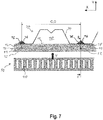
Figure 8 shows a cross sectional view II-II of the wall configuration offigure 7 , -
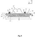
Figure 9 shows a first step of a method according to a further embodiment of the invention for installing a wall configuration to a fluted metal deck with corrugations, -
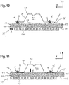
Figure 10 shows a second step of the method offigure 9 , and -
Figure 11 shows a third step of the method offigure 9 . -
Figure 1 shows a section of atop track seal 10 comprising a sealingstrip 12 and multiple sealingelements - The sealing
strip 12 is pre-formed and has aseat 18 for a top track 20 (seefigure 8 ) on itsbottom side 22 that runs in longitudinal direction X. - The sealing
strip 12 can be produced as one integral part, for example from polyurethane foam. - The sealing
strip 12 can also be produced from any other air-tight, sound-attenuating or even sound-proof, fire-resistant, smoke-proof and/or thermally isolating material. - The material, the sealing
strip 12 is made of, is generally resilient. - On the
top side 24 of the sealingstrip 12 which is located opposite to the bottom side 22 (seefigure 2 ), the sealingelements strip 12 and protrude from thetop side 24. - The sealing
elements identical sets - The distance B corresponds to the width T of the
top track 20 in direction A (seefigure 8 ). - The
top track seal 10 is designed to seal a movement joint 31 between ametal deck 30 and an adjacent wall configuration 32 (seefigure 8 ). Themetal deck 30 comprises one or more flutedmetal deck elements 34 withparallel corrugations 36. The sealingelements corrugations 36 when thetop track seal 10 is mounted on thelower side 38 of thefluted metal deck 30. - To this end, each set 26, 28 comprises multiple sealing
elements consecutive sealing elements consecutive sealing elements consecutive corrugations 36 of themetal deck 30. - The
top track seal 10 is pre-manufactured to seal the regular distancedcorrugations 36 of ametal deck 30. In the case that not allcorrugations 36 are spaced equally apart, the distances between twoconsecutive sealing elements corrugations 36 in themetal deck 30. In this way, thetop track seal 10 is adapted to seal the movement joint 31, wherein the sealingelements respective corrugations 36 of thefluted metal deck 30 adjacent to the wall configuration. -
Figure 4 shows a cross sectional view of a section of ametal deck element 34 with twoflutes 40 and acorrugation 36 extending in direction A (see alsofigure 8 ) that runs perpendicular to the drawing plane infigure 4 . - The
corrugation 36 has a generally triangular cross section with a depth h and a width w when seen in mounted state in direction A, which is the perspective taken infigure 4 . -
Figures 5 and 6 show one of the sealingelements top track seal 10. - The sealing
element figure 5 , as well as a length L the sealingelement - The height H of the sealing
element corrugation 36. In this way, the sealingelement corrugation 36 when inserted in thecorrugation 36 so that it can be pressed more easily into thecorrugation 36 to ensure a tight fit. - Further the maximum width W of the sealing
element corrugation 36, ensuring a tight seal. - As a result of the, the cross sectional area of the sealing
element corrugation 36. This ensures that enough sealing material is provided to securely seal the corrugation. - The length L of the sealing
element element figure 2 ). - The sealing
element - In a different embodiment the sealing
element - In an alternative embodiment the sealing
element - In a further embodiment, the sealing
element - Furthermore, the sealing
element corrugation 36 when applied to thecorrugation 36. Thus, the sealing properties of the sealingelement elastic sealing element corrugation 36, even when the sealingelement - The sealing
element corrugation 36 it is designed to seal. - In this way, the sealing
element corrugation 36 by its predefined shape and size. - The embodiment of the sealing
element figures 5 and 6 has a cross section with a shape that corresponds to the shape of the cross section of thecorrugation 36 as both cross sections are triangular with a similar shape. - Because the sealing
element corrugation 36. This is the case if the cross sectional area of the sealingelement corrugation 36. Also, for corrugations 36 with no or minimal undercuts a tight seal can be ensured if the height H and the width W of the sealingelement corrugation 36 respectively. - In this way, the sealing
element corrugation 36 in the flutedmetal deck element 34. Further, the sealingelement metal deck elements 34, wherein the corrugation corresponds in size and shape to thecorrugation 36 in the flutedmetal deck element 34. - Further, by being moldable, the sealing
element corrugations 36 between adjacent flutedmetal deck elements 34, even if the shape of acorrugation 36 between adjacent flutedmetal deck elements 34 differs from the shape of acorrugation 36 in the flutedmetal deck element 34. - All sealing
elements figure 1 ). - In an alternative embodiment, one or more of the sealing
elements elements top track seal 10 can comprise sealingelements element - As shown in
figure 1 , the sealingelements 14 of thefirst set 26 and the sealingelements 16 of thesecond set 28 are aligned in such a way that the sealingelements element 14 of thefirst set 26 has acorresponding sealing element 16 of thesecond set 28, wherein both are aligned in direction A. In this way, thetop track seal 10 provides two sealingelements corrugation 36. So when thetop track seal 10 is mounted to the fluted metal deck 30 (seefigure 8 ), eachcorrugation 36 is sealed by two sealingelements - In an alternative embodiment, the
top track seal 10 can only comprise asingle set 26 of two or more sealing elements 14 (seefigure 3 ). In this case, there is only asingle sealing element 14 provided to seal eachcorrugation 36. - The
set 26 of sealingelements 14 is preferably positioned equally distanced to thesides -
Figure 7 shows anassembly 50 comprising thetop track seal 10 and a correspondingtop track 20. - The
top track seal 10 has arrow shapedmarkings 52 on itssides elements elements top track seal 10 is facilitated as the sealingelements respective corrugations 36 of themetal deck 30. - The
assembly 50 is part of the wall configuration 32 (seefigure 8 ) and is designed to be mounted on alower side 38 of thefluted metal deck 30 to seal thecorrugations 36. - Further, the
top track seal 10 is adapted to seal the movement joint 31. - The
wall configuration 32 is a drywall configuration. - In the example shown, the
wall configuration 32 further comprises twogypsum boards 54. - The wall plane of the
wall configuration 32 is defined by the longitudinal direction X and the vertical direction V in which both the wall plane extends in. - In the embodiment, the wall plane of the
wall configuration 32 is positioned substantially perpendicular to the direction A in which theflutes 40 andcorrugations 36 of thefluted metal deck 30 extend in as well as substantially perpendicular to the plane defined by thefluted metal deck 30. - The axis of the
flutes 40 extends in direction A. - To install the
wall configuration 32 to thefluted metal deck 30 the following method is used. - The
top track seal 10 is positioned on thelower side 38 of the fluted metal deck 30 (seefigure 7 ), in a way that the sealingelements respective corrugations 36 of thefluted metal deck 30. - The sealing
elements corrugation 36 with enough pressure in direction V, so that thetop track seal 10 adheres to themetal deck 30. Due to the self-adhesive properties of the sealingelements top track seal 10 remains temporally in place without the need of additional fixing elements. - Afterwards, the
top track 20 is inserted into theseat 18 of the sealingstrip 12 and then fixed to thefluted metal deck 30. Thereby, thetop track seal 10 is fixed to themetal deck 30 and the sealingelements corrugations 36 sealing them tight in the process. - The
top track 20 can be fixed to thefluted metal deck 30 with fastening means, like anchors, bolts and/or nails. - In an alternative embodiment, the
assembly 50 is positioned as a whole on thelower side 38 of thefluted metal deck 30, in a way that the sealingelements respective corrugations 36 of thefluted metal deck 30. This means that thetop track 20 is already arranged in theseat 18 and thus does not have to be inserted after thetop track seal 10 is positioned to thefluted metal deck 30. - In a different embodiment, the length N of the
top track seal 10 is larger than the length M of thetop track 20 in the longitudinal direction X (seefigure 9 ). This has the advantage that thetop track 20 can be positioned within the sealingstrip 12 independently from thetop track seal 10 relative to themetal deck 30. - To mount the
assembly 50 to thefluted metal deck 30, the sealingelements corrugation 36 with enough pressure in direction V, so that thetop track seal 10 adheres to themetal deck 30. Due to the self-adhesive properties of the sealingelements top track seal 10 remains temporally in place with no need for additional fixing elements. - Because the height H of the sealing
elements corrugations 36, the sealingelements fluted metal deck 30 out of the corrugation 36 (seefigures 9 and10 ). - As shown in
figure 10 , after thetop track seal 10 is temporally attached to themetal deck 30, thetop track 20 can be slid inside theseat 18 in longitudinal direction X into a desired position relative to thetop track seal 10 and themetal deck 30 while thetop track seal 10 stays substantially in its place. This staying in place is achieved solely by the adhesive properties of the sealingelements - In an alternative embodiment, where the friction between the
top track 20 and thetop track seal 10 is higher than the adhesive forces between the sealingelements metal deck 30, the position of thetop track seal 10 relative to themetal deck 30 can be kept by manually holding thetop track seal 10 in place during these events. - After the
top track seal 10 and thetop track 20 are in position, the top track is fixed to thefluted metal deck 30. Thereby, thetop track seal 10 is fixed to themetal deck 30 and the protruding sealingelements corrugation 36 which results in the sealingelements corrugations 36 and sealing thecorrugations 36 tight. - All methods described above can also be executed with top track seals 10 with
non-adhesive sealing elements top track seal 10 relative to themetal deck 30 has to be kept steady by other means, for example by manually holding thetop track seal 10 or by fixing it with fastening means. - The
top track seal 10 and theassembly 50 as well as the method described above improve the sealing ofcorrugations 36 of aflute metal deck 30 in the following ways:
Thecorrugations 36 can be tightly sealed in a short amount of time without the need of additional tools. - The sealing
elements top track seal 10. In this way, thecorrugations 36 are easily accessible and no additional "ladder climbing" is required. - The sealing of the
corrugations 36 is failure proof as the pre-manufacturedtop track seal 10 withpre-proportioned sealing elements - Further, the sealing of the
corrugations 36 requires no curing time because the material, the sealingelements - The invention is not limited to the embodiments shown. In particular, individual features of an embodiment can be contained in a further inventive embodiment independently of the other features of the corresponding embodiment, i.e. the described features can be freely combined.
Claims (11)
- A top track seal (10) for sealing a movement joint (31) between a fluted metal deck (30) and an adjacent wall configuration (32), preferably a drywall configuration, the top track seal (10) comprising a pre-formed sealing strip (12) adapted to seal the movement joint (31), and a first set (26) of two or more sealing elements (14) for sealing corrugations (36) of the fluted metal deck (30), wherein the sealing strip (12) comprises a seat (18) for a top track (20), wherein the sealing elements (14) protrude from a side (24) of the sealing strip (12) designed to face the metal deck (30) in mounted state, wherein the sealing elements (14) are spaced apart in the longitudinal direction (X) of the sealing strip (12) and the distance (C) between two consecutive sealing elements (14) corresponds to the distance (D) between two consecutive corrugations (36) of the metal deck (30), wherein each sealing element (14) is moldable and has a predefined geometry adapted to seal a corrugation (36) between adjacent fluted deck elements (34) or in one of the fluted deck elements (34).
- The top track seal according to claim 1, characterized in that the top track seal (10) comprises a second set (28) of sealing elements (16) which is designed identical to the first set (26) of sealing elements (14), wherein the first set (26) and the second set (28) are spaced apart crosswise to the longitudinal direction (X) of the sealing strip (12).
- The top track seal according to claim 2, characterized in that the distance (B) between the first set (26) and the second set (28) crosswise to the longitudinal direction (X) of the sealing strip (12) correlates to the width (T) of the top track (20).
- The top track seal according to any preceding claim, characterized in that the shape of the cross section of each sealing element (14, 16) corresponds to the shape of the cross section of a corrugation (36) and/or that the orientation of each sealing element (14, 16) is adapted to seal a corrugation (36).
- The top track seal according to any preceding claim, characterized in that the sealing elements (14, 16) are made from an air-tight, sound-attenuating or even sound-proof, fire-resistant, smoke-proof and/or thermally isolating material, especially a putty or a butyl.
- The top track seal according to any preceding claim, characterized in that the sealing elements (14, 16) are self-adhesive.
- Assembly (50) comprising a top track seal (10) according to any preceding claim and a top track (20).
- The assembly according to claim 7, characterized in that the top track seal (10) is longer in longitudinal direction (X) than the top track (20).
- A method for installing a wall configuration (32), preferably a drywall configuration, to a fluted metal deck (30) with corrugations (36), wherein a wall plane of the wall configuration (32) is positioned substantially perpendicular to a flute axis (A), wherein the wall configuration (32) comprises an assembly (50) according to claim 7 or 8 being mounted on a lower side (38) of the fluted metal deck (30), comprising the following steps:a) positioning the assembly (50) on the lower side (38) of the fluted metal deck (30), wherein the sealing elements (14, 16) are positioned in the corrugations (36) of the fluted metal deck (30), andb) fixing the top track (20) to the fluted metal deck (30), whereby the sealing elements (14, 16) are pressed into the corrugations (36).
- A method for installing a wall configuration (32), preferably a drywall configuration, to a fluted metal deck (30) with corrugations (36), wherein a wall plane of the wall configuration (32) is positioned substantially perpendicular to a flute axis (A), wherein the wall configuration (32) comprises an assembly (50) according to claim 8 being mounted on a lower side (38) of the fluted metal deck (30), comprising the following steps:a) positioning the assembly (50) on the lower side (38) of the fluted metal deck (30), wherein the sealing elements (14, 16) are positioned in the corrugations (36) of the fluted metal deck (30),b) positioning the top track (20) within the seat (18) of the sealing strip (12), andc) fixing the top track (20) to the fluted metal deck (30), whereby the sealing elements (14, 16) are pressed into the corrugations (36).
- A method for installing a wall configuration (32), preferably a drywall configuration, to a fluted metal deck (30) with corrugations (36), wherein a wall plane of the wall configuration (32) is positioned substantially perpendicular to a flute axis (A), wherein the wall configuration (32) comprises an assembly (50) according to claim 7 or 8 as well as claim 6 being mounted on a lower side (38) of the fluted metal deck (30), comprising the following steps:a) positioning the top track seal (10) on the lower side (38) of the fluted metal deck (30), wherein the sealing elements (14, 16) are positioned in the corrugations (36) of the fluted metal deck (30),b) inserting the top track (20) into the seat (18) of the sealing strip (12), andc) fixing the top track (20) to the fluted metal deck (30), whereby the sealing elements (14, 16) are pressed into the corrugations (36).
Priority Applications (6)
| Application Number | Priority Date | Filing Date | Title |
|---|---|---|---|
| EP18167439.1A EP3556956A1 (en) | 2018-04-16 | 2018-04-16 | Top track seal, assembly and method for installing a wall configuration |
| CA3092012A CA3092012A1 (en) | 2018-04-16 | 2019-04-08 | Top track seal, assembly and method for installing a wall configuration |
| PCT/EP2019/058805 WO2019201645A1 (en) | 2018-04-16 | 2019-04-08 | Top track seal, assembly and method for installing a wall configuration |
| AU2019256495A AU2019256495A1 (en) | 2018-04-16 | 2019-04-08 | Top track seal, assembly and method for installing a wall configuration |
| EP19715491.7A EP3781757A1 (en) | 2018-04-16 | 2019-04-08 | Top track seal, assembly and method for installing a wall configuration |
| US15/733,533 US20210087812A1 (en) | 2018-04-16 | 2019-04-08 | Top track seal, assembly and method for installing a wall configuration |
Applications Claiming Priority (1)
| Application Number | Priority Date | Filing Date | Title |
|---|---|---|---|
| EP18167439.1A EP3556956A1 (en) | 2018-04-16 | 2018-04-16 | Top track seal, assembly and method for installing a wall configuration |
Publications (1)
| Publication Number | Publication Date |
|---|---|
| EP3556956A1 true EP3556956A1 (en) | 2019-10-23 |
Family
ID=62044494
Family Applications (2)
| Application Number | Title | Priority Date | Filing Date |
|---|---|---|---|
| EP18167439.1A Withdrawn EP3556956A1 (en) | 2018-04-16 | 2018-04-16 | Top track seal, assembly and method for installing a wall configuration |
| EP19715491.7A Withdrawn EP3781757A1 (en) | 2018-04-16 | 2019-04-08 | Top track seal, assembly and method for installing a wall configuration |
Family Applications After (1)
| Application Number | Title | Priority Date | Filing Date |
|---|---|---|---|
| EP19715491.7A Withdrawn EP3781757A1 (en) | 2018-04-16 | 2019-04-08 | Top track seal, assembly and method for installing a wall configuration |
Country Status (5)
| Country | Link |
|---|---|
| US (1) | US20210087812A1 (en) |
| EP (2) | EP3556956A1 (en) |
| AU (1) | AU2019256495A1 (en) |
| CA (1) | CA3092012A1 (en) |
| WO (1) | WO2019201645A1 (en) |
Cited By (1)
| Publication number | Priority date | Publication date | Assignee | Title |
|---|---|---|---|---|
| US11111669B1 (en) * | 2019-08-29 | 2021-09-07 | Tony J. Ballew | Positioning and support tool for steel stud framing |
Citations (6)
| Publication number | Priority date | Publication date | Assignee | Title |
|---|---|---|---|---|
| US5913788A (en) * | 1997-08-01 | 1999-06-22 | Herren; Thomas R. | Fire blocking and seismic resistant wall structure |
| US20160017598A1 (en) * | 2014-07-21 | 2016-01-21 | Hilti Aktiengesellschaft | Insulating Sealing Element for Construction Joints |
| JP2016037717A (en) * | 2014-08-06 | 2016-03-22 | 新日鐵住金株式会社 | Synthetic slab |
| US20170314256A1 (en) * | 2013-11-18 | 2017-11-02 | Hilti Aktiengesellschaft | Insulating Sealing Element for Head-of-Wall Joints |
| US20180002917A1 (en) * | 2015-02-13 | 2018-01-04 | Hilti Aktiengesellschaft | Universal joint sealing tape for different profile dimensions and seal arrangement having such a joint sealing tape |
| EP3284872A1 (en) * | 2016-08-18 | 2018-02-21 | HILTI Aktiengesellschaft | Sealing element for connecting a dry wall |
-
2018
- 2018-04-16 EP EP18167439.1A patent/EP3556956A1/en not_active Withdrawn
-
2019
- 2019-04-08 US US15/733,533 patent/US20210087812A1/en not_active Abandoned
- 2019-04-08 WO PCT/EP2019/058805 patent/WO2019201645A1/en not_active Ceased
- 2019-04-08 CA CA3092012A patent/CA3092012A1/en not_active Abandoned
- 2019-04-08 EP EP19715491.7A patent/EP3781757A1/en not_active Withdrawn
- 2019-04-08 AU AU2019256495A patent/AU2019256495A1/en not_active Abandoned
Patent Citations (6)
| Publication number | Priority date | Publication date | Assignee | Title |
|---|---|---|---|---|
| US5913788A (en) * | 1997-08-01 | 1999-06-22 | Herren; Thomas R. | Fire blocking and seismic resistant wall structure |
| US20170314256A1 (en) * | 2013-11-18 | 2017-11-02 | Hilti Aktiengesellschaft | Insulating Sealing Element for Head-of-Wall Joints |
| US20160017598A1 (en) * | 2014-07-21 | 2016-01-21 | Hilti Aktiengesellschaft | Insulating Sealing Element for Construction Joints |
| JP2016037717A (en) * | 2014-08-06 | 2016-03-22 | 新日鐵住金株式会社 | Synthetic slab |
| US20180002917A1 (en) * | 2015-02-13 | 2018-01-04 | Hilti Aktiengesellschaft | Universal joint sealing tape for different profile dimensions and seal arrangement having such a joint sealing tape |
| EP3284872A1 (en) * | 2016-08-18 | 2018-02-21 | HILTI Aktiengesellschaft | Sealing element for connecting a dry wall |
Cited By (1)
| Publication number | Priority date | Publication date | Assignee | Title |
|---|---|---|---|---|
| US11111669B1 (en) * | 2019-08-29 | 2021-09-07 | Tony J. Ballew | Positioning and support tool for steel stud framing |
Also Published As
| Publication number | Publication date |
|---|---|
| US20210087812A1 (en) | 2021-03-25 |
| WO2019201645A1 (en) | 2019-10-24 |
| CA3092012A1 (en) | 2019-10-24 |
| EP3781757A1 (en) | 2021-02-24 |
| AU2019256495A1 (en) | 2020-09-17 |
Similar Documents
| Publication | Publication Date | Title |
|---|---|---|
| US12116775B2 (en) | Sealing element, seal and method for installing a wall configuration | |
| US10472819B2 (en) | Isolation block, method for sealing a flute of a fluted metal deck, and wall and deck configuration | |
| US10196811B2 (en) | Insulating sealing element for head-of-wall joints | |
| US20150275507A1 (en) | Insulating sealing element for head-of-wall joints | |
| US20160017599A1 (en) | Insulating Sealing Element for Head-of-Wall Joints | |
| CA2849597C (en) | Adjustable head-of-wall insulation construction for use with wider wall configurations | |
| US8826599B2 (en) | Insulating gasket construction for head-of-wall joints | |
| US8181404B2 (en) | Head-of-wall fireblocks and related wall assemblies | |
| US10920416B2 (en) | Drywall and sealing device for sealing a connection joint of a drywall | |
| US20150135622A1 (en) | Insulating sealing element for head-of-wall joints | |
| US20150275510A1 (en) | Intumescent sealing element for head-of-wall joints | |
| US20150275506A1 (en) | Insulating sealing element for head-of-wall joints | |
| EP3296480A1 (en) | Thermal and acoustic insulating and sealing system for fluted deck constructions | |
| US20110185656A1 (en) | Fire retardant cover for fluted roof deck | |
| CA2697295A1 (en) | Fire-rated wall construction product | |
| US20260035909A1 (en) | Sealing device for edge joints and drywall | |
| US20210087812A1 (en) | Top track seal, assembly and method for installing a wall configuration | |
| HK1241947A1 (en) | Universal joint sealing strip for different profile dimensions, and sealing arrangement having a joint sealing strip of this type | |
| WO2016200310A1 (en) | Wall trimming system and method |
Legal Events
| Date | Code | Title | Description |
|---|---|---|---|
| PUAI | Public reference made under article 153(3) epc to a published international application that has entered the european phase |
Free format text: ORIGINAL CODE: 0009012 |
|
| AK | Designated contracting states |
Kind code of ref document: A1 Designated state(s): AL AT BE BG CH CY CZ DE DK EE ES FI FR GB GR HR HU IE IS IT LI LT LU LV MC MK MT NL NO PL PT RO RS SE SI SK SM TR |
|
| AX | Request for extension of the european patent |
Extension state: BA ME |
|
| STAA | Information on the status of an ep patent application or granted ep patent |
Free format text: STATUS: THE APPLICATION IS DEEMED TO BE WITHDRAWN |
|
| 18D | Application deemed to be withdrawn |
Effective date: 20200603 |