EP3556946A1 - Work vehicle with improved stability - Google Patents
Work vehicle with improved stability Download PDFInfo
- Publication number
- EP3556946A1 EP3556946A1 EP18168580.1A EP18168580A EP3556946A1 EP 3556946 A1 EP3556946 A1 EP 3556946A1 EP 18168580 A EP18168580 A EP 18168580A EP 3556946 A1 EP3556946 A1 EP 3556946A1
- Authority
- EP
- European Patent Office
- Prior art keywords
- axis
- trough
- work vehicle
- unit
- vehicle
- Prior art date
- Legal status (The legal status is an assumption and is not a legal conclusion. Google has not performed a legal analysis and makes no representation as to the accuracy of the status listed.)
- Granted
Links
- 230000005484 gravity Effects 0.000 claims abstract description 9
- 230000008878 coupling Effects 0.000 claims abstract description 3
- 238000010168 coupling process Methods 0.000 claims abstract description 3
- 238000005859 coupling reaction Methods 0.000 claims abstract description 3
- 238000010276 construction Methods 0.000 description 2
- 239000000463 material Substances 0.000 description 2
- 239000013590 bulk material Substances 0.000 description 1
- 238000002485 combustion reaction Methods 0.000 description 1
- 238000011161 development Methods 0.000 description 1
- 230000018109 developmental process Effects 0.000 description 1
- 230000002349 favourable effect Effects 0.000 description 1
- 238000005259 measurement Methods 0.000 description 1
- 239000002689 soil Substances 0.000 description 1
- 210000000689 upper leg Anatomy 0.000 description 1
Images
Classifications
-
- E—FIXED CONSTRUCTIONS
- E02—HYDRAULIC ENGINEERING; FOUNDATIONS; SOIL SHIFTING
- E02F—DREDGING; SOIL-SHIFTING
- E02F9/00—Component parts of dredgers or soil-shifting machines, not restricted to one of the kinds covered by groups E02F3/00 - E02F7/00
- E02F9/16—Cabins, platforms, or the like, for drivers
- E02F9/166—Cabins, platforms, or the like, for drivers movable, tiltable or pivoting, e.g. movable seats, dampening arrangements of cabins
-
- B—PERFORMING OPERATIONS; TRANSPORTING
- B60—VEHICLES IN GENERAL
- B60N—SEATS SPECIALLY ADAPTED FOR VEHICLES; VEHICLE PASSENGER ACCOMMODATION NOT OTHERWISE PROVIDED FOR
- B60N2/00—Seats specially adapted for vehicles; Arrangement or mounting of seats in vehicles
- B60N2/02—Seats specially adapted for vehicles; Arrangement or mounting of seats in vehicles the seat or part thereof being movable, e.g. adjustable
- B60N2/04—Seats specially adapted for vehicles; Arrangement or mounting of seats in vehicles the seat or part thereof being movable, e.g. adjustable the whole seat being movable
- B60N2/14—Seats specially adapted for vehicles; Arrangement or mounting of seats in vehicles the seat or part thereof being movable, e.g. adjustable the whole seat being movable rotatable, e.g. to permit easy access
- B60N2/143—Seats specially adapted for vehicles; Arrangement or mounting of seats in vehicles the seat or part thereof being movable, e.g. adjustable the whole seat being movable rotatable, e.g. to permit easy access taking a position opposite to the original one
-
- B—PERFORMING OPERATIONS; TRANSPORTING
- B60—VEHICLES IN GENERAL
- B60N—SEATS SPECIALLY ADAPTED FOR VEHICLES; VEHICLE PASSENGER ACCOMMODATION NOT OTHERWISE PROVIDED FOR
- B60N2/00—Seats specially adapted for vehicles; Arrangement or mounting of seats in vehicles
- B60N2/24—Seats specially adapted for vehicles; Arrangement or mounting of seats in vehicles for particular purposes or particular vehicles
-
- B—PERFORMING OPERATIONS; TRANSPORTING
- B62—LAND VEHICLES FOR TRAVELLING OTHERWISE THAN ON RAILS
- B62D—MOTOR VEHICLES; TRAILERS
- B62D53/00—Tractor-trailer combinations; Road trains
- B62D53/02—Tractor-trailer combinations; Road trains comprising a uniaxle tractor unit and a uniaxle trailer unit
-
- E—FIXED CONSTRUCTIONS
- E02—HYDRAULIC ENGINEERING; FOUNDATIONS; SOIL SHIFTING
- E02F—DREDGING; SOIL-SHIFTING
- E02F3/00—Dredgers; Soil-shifting machines
- E02F3/04—Dredgers; Soil-shifting machines mechanically-driven
- E02F3/28—Dredgers; Soil-shifting machines mechanically-driven with digging tools mounted on a dipper- or bucket-arm, i.e. there is either one arm or a pair of arms, e.g. dippers, buckets
- E02F3/34—Dredgers; Soil-shifting machines mechanically-driven with digging tools mounted on a dipper- or bucket-arm, i.e. there is either one arm or a pair of arms, e.g. dippers, buckets with bucket-arms, i.e. a pair of arms, e.g. manufacturing processes, form, geometry, material of bucket-arms directly pivoted on the frames of tractors or self-propelled machines
-
- E—FIXED CONSTRUCTIONS
- E02—HYDRAULIC ENGINEERING; FOUNDATIONS; SOIL SHIFTING
- E02F—DREDGING; SOIL-SHIFTING
- E02F9/00—Component parts of dredgers or soil-shifting machines, not restricted to one of the kinds covered by groups E02F3/00 - E02F7/00
- E02F9/08—Superstructures; Supports for superstructures
- E02F9/0841—Articulated frame, i.e. having at least one pivot point between two travelling gear units
-
- B—PERFORMING OPERATIONS; TRANSPORTING
- B62—LAND VEHICLES FOR TRAVELLING OTHERWISE THAN ON RAILS
- B62D—MOTOR VEHICLES; TRAILERS
- B62D21/00—Understructures, i.e. chassis frame on which a vehicle body may be mounted
- B62D21/18—Understructures, i.e. chassis frame on which a vehicle body may be mounted characterised by the vehicle type and not provided for in groups B62D21/02 - B62D21/17
- B62D21/186—Understructures, i.e. chassis frame on which a vehicle body may be mounted characterised by the vehicle type and not provided for in groups B62D21/02 - B62D21/17 for building site vehicles or multi-purpose tractors
Definitions
- the invention relates to a work vehicle having a drive unit and a tray unit, which are coupled to a joint arranged between the drive unit and the tray unit.
- Such work vehicles are commonly used on construction sites to transport material.
- On the driving unit usually the engine and the operator workstation are arranged.
- On the trough unit a trough for receiving the material to be transported is arranged.
- Drive unit and trough unit are coupled to each other by means of a joint, for example by means of a kinked pendulum joint.
- the steering takes place by means of a pivoting of the driving unit and the trough unit about an axis which is formed by means of the joint.
- a generic work vehicle is for example from the DE 10 2015 001 905 known.
- Such work vehicles transport in comparison to their own weight high loads and often drive unpaved roads.
- the manufacturers of such machines are therefore constantly striving to optimize the stability of these work vehicles.
- the operators have to assume an elevated seating position in order to have a sufficient overview even when the vehicle is laden.
- the object of the invention is therefore to provide a working vehicle, which can move stably and safely on uneven ground even at high loads and also allows the driver to safely drive the vehicle.
- a work vehicle with a drive unit, which has a drive motor and a first axis with two associated wheels, and a trough unit having a trough for receiving a load and a second axle with two associated wheels, wherein between the driving unit and the trough unit a joint is arranged for coupling the driving unit to the trough unit, in such a way that the driving unit and the trough unit are movable relative to each other about at least one vertical axis Z of the working vehicle are in an extended position of the working vehicle (ie in a position in which the two axes extend parallel to each other) between an axial center of the axis of rotation of the first axis and an axial center of the axis of rotation of the second axis, a horizontal distance X is present and a horizontal distance between the center of the first axis and a payload center of gravity of the working vehicle is selected such that its value is in a range of 0.84 X +/- 10%, and a horizontal distance between a
- the axial center of the first axis or the second axis is thus understood to mean a point which is located on the respective axis of rotation defined by the rotation of the wheel hubs carried by the respective axles, with respect to the distance between the respective end faces Axles arranged wheel hubs lying in the middle between the wheel hubs.
- the distance between the axes is used. In this case, from the two centers of the wheels, i. especially the axes of rotation of the hubs measured. All measurements of the values, as they are called in the present application, take place when the work vehicle is horizontal, in the extended position.
- the work vehicle is in an extended position when the axes of the tray unit and the drive unit are parallel to each other, i. if there is no pivoting about the vertical axis Z In this position, the work vehicle would go straight ahead.
- the payload center of gravity is the center of gravity of the maximum nominal payload in the trough accommodated in the trough.
- the nominal payload is the payload for which the work vehicle is designed and / or approved.
- the payload center of gravity is determined by the arrangement of the trough on the trough unit.
- the payload is considered to be a load typical of the work vehicle, e.g. Soil.
- the working vehicle has a main driving direction, in which the trough unit follows in the direction of travel of the driving unit.
- the drive in the main direction of travel can also be referred to as forward travel.
- the driver has the trough and thus the payload in the back and thus a clear view of the route to be traveled.
- a vehicle seat for an operator which can be rotatably arranged, wherein the working vehicle is movable both in the main direction of travel, as well as in a Maufahrraum is movable, in which the driving unit of the trough unit follows, the vehicle seat in the Maufahrraum is aligned in the direction of the trough unit.
- the Maufahrraum can also be referred to as reverse drive.
- the rotatable seat is pivotable by at least 150 °, preferably by 180 °, so that the driver sits in reverse direction in the direction of travel. He looks in the direction of the trough unit, which now moves ahead, so that the drive unit follows the trough unit.
- the work vehicle may be designed such that a vertical distance between a center of the first axis and a center of a crankshaft of a drive motor is selected such that it lies in a range of 0.13 X +/- 10%.
- the engine which has a significant influence on the stability of the work vehicle by its weight, is in a preferred position.
- a vertical distance between a center of the first axis and a seat index point may be selected to be within a range of 0.52 X +/- 10%.
- the seat index point is a point specified in the field of earthmoving machinery and is defined by DIN EN ISO 5353 in the version valid at the time of registration. The seat index point is therefore clearly defined for each machine of each manufacturer and suitable as a reference point. The seat index point is a characteristic value for the seat and can therefore be specified directly by any seat manufacturer or vehicle manufacturer. The seat index point is fixed with respect to the machine and does not change its position by the range of adjustment and / or swing of the seat.
- the seat index point information relates to the position of the seat in the main travel direction.
- the seat index point is equal to the intersection between the theoretical axes of the human torso of an operator and the human thigh on the vertical plane through the center line of the seat.
- the work vehicle has a cabin in which the vehicle seat is arranged. This increases the comfort for the operator.
- the work vehicle is characterized in that a vertical distance between the seat index point and a roof underside of a cabin is selected such that it lies in a range of 0.37 X +/- 10%.
- a valve cover of the drive motor is arranged above a bottom surface of the cabin.
- the valve cover is usually the highest point of the engine for inline engines. Alternatively, generally, the highest point of the engine, i. in particular the engine block and / or the cylinder head are considered.
- Another variant is to arrange an upper edge of the trough in a driving position above the seat index point.
- the upper edge of the trough is the highest point of the trough.
- the driving position of the trough is usually the position in which the trough is positioned substantially horizontally and a tilting system of the trough is retracted. The tilting edge of the trough points against the main direction of travel.
- the trough may be pivoted relative to the trough unit about a vertical axis H, wherein an envelope of the trough has a diameter of 1.31 X +/- 10%.
- the trough has for this purpose a pivoting device by means of which the trough from a central position, with an angle of at least 80 ° can be pivoted to both sides of the machine.
- the envelope results in a plan view of the work vehicle as an imaginary curve, which is described at a pivoting of the trough between their maximum end positions.
- the trough is in driving position.
- the diameter of the envelope of the trough is in relation to the axial distance as a measure of the stability of the working vehicle, since when loaded trough a corresponding support by means of the width of the axles and the tires must be provided.
- the choice of the diameter of the enveloping circle is preferred as a fixed measure.
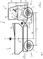
- the single figure shows a schematic, not to scale side view of a work vehicle, in particular a so-called dumper.
- the working vehicle 1 has a driving unit 2 and a trough unit 3, which are coupled to a hinge 9 in such a way that an articulated steering results by means of the vertical axis Z formed thereby.
- first axis 5 serving as a front axle first axis 5 is provided at the front ends of which wheel hubs are arranged, which carry corresponding wheels 7 in a known manner.
- second axis 6 serving as a rear axle second axis 6 is provided on the trough unit 3, at the front ends of which wheel hubs are likewise arranged, which carry corresponding wheels 7.
- the first and second axes 5, 6 are rigid, i. firmly arranged in their orientation to the respective driving unit 2 and trough unit 3.
- the first axis 5 is arranged on the driving unit 2.
- a drive motor 4 which is an internal combustion engine in the example shown, but can also be configured as an electric motor.
- a vehicle seat 12, a steering wheel 19 and a cab 16 are arranged on the driving unit 2.
- the cab 16 is optional and could also be replaced by a roll bar.
- the second axis 6 and a trough 8 are arranged.
- the trough 8 serves to receive the payload, in particular bulk material, and can be tilted with an unloading device, not shown.
- the work vehicle 1 can move in the main travel direction 11 by means of the drive motor 4.
- the driving unit 2 moves ahead and the tray unit 3 follows.
- the driver's seat 12 is aligned in the direction of the main travel direction 11 so that an operator looks in the direction of the main travel direction 11.
- the driver's seat 12 is designed to be rotatable so that it can be rotated when the working vehicle 1 is to travel in a secondary driving direction 13, ie, backwards.
- a secondary driving direction 13 ie, backwards.
- the necessary for the operation of the vehicle controls are also designed to be rotatable and / or double available.
- the tray unit 3 moves ahead and the drive unit 2 follows this. The operator can look on the rotated seat 12 in the direction of the secondary driving direction 13, which makes the drive safer.
- the work vehicle is driven by means of the drive motor 4.
- a hydraulic pump is arranged on the engine, which supplies the necessary pressure or volume flow in order to drive a hydraulic motor.
- the hydraulic motor drives the wheels.
- the other functions, such as the drive of the tilting system of the trough and also the pivoting of the trough and the articulated steering are hydrostatically driven by the hydraulic pump.
- the vehicle seat 12 is rotatable. This allows higher speeds in the reverse drive, so that the work vehicle as stable as possible, not only in forward drive but also in reverse drive, i. must be stable. However, the greatest possible safety is also necessary for machines which do not have a rotatable driver's seat, so that a rotatable driver's seat is not a feature which is necessary according to the invention.
- the wheelbase i. the distance between the first and second axis proved to be suitable.
- the horizontal distance X between the center of the axis of rotation of the first axis 5 and the center of the axis of rotation of the second axis 6 is 2700 mm in the embodiment.
- the center here is understood to be the middle between the wheel hubs respectively arranged at the ends of the axles 5, 6.
- the vertical distance Y2 to a center point or the axis of rotation of the first axis 5 and the seat index point 15 in the exemplary embodiment is 1403 mm. As a relation to the distance X, this results in 0.52.
- the vertical distance Y3 between the seat index point 15 and a roof bottom of the cab 16 is 1000mm. As a relation to the distance X, this results in 0.37.
- the diameter of an envelope in the selected embodiment is 3530mm. As a relation to the distance X, this results in 1.31.
- the relationship between the vertical distance Y2 between the axial center of the first axis 5 and the seat index point 15 and the vertical distance Y3 between the seat index point 15 and the roof bottom of the car 16 has been characteristic.
- the dimensions are in the selected embodiment for the distance from the axis 5 and the seat index point 1403 mm and for the distance from the seat index point 15 and the roof bottom of the cabin 1000mm.
Abstract
Beschrieben wird ein Arbeitsfahrzeug (1) mit einer Fahreinheit (2), die einen Antriebsmotor (4) sowie eine erste Achse (5) mit zwei zugeordneten Rädern (7) aufweist; einer Muldeneinheit (3), die eine Mulde (8) zum Aufnehmen einer Last sowie eine zweite Achse (6) mit zwei zugeordneten Rädern (7) aufweist, einem zwischen der Fahreinheit (2) und der Muldeneinheit (3) angeordneten Gelenk (9) zum Koppeln der Fahreinheit (2) mit der Muldeneinheit (3), derart, dass die Fahreinheit (2) und die Muldeneinheit (3) um wenigstens eine Hochachse Z des Arbeitsfahrzeugs (1) relativ zueinander bewegbar sind; wobei in einer gestreckten Position des Arbeitsfahrzeugs (1) zwischen einem vertikalen Mittelpunkt der ersten Achse (5) und einem vertikalen Mittelpunkt der zweiten Achse (6) ein horizontaler Abstand X vorliegt, ein horizontaler Abstand zwischen dem Mittelpunkt der ersten Achse (5) und einem Nutzlastschwerpunkt (10) des Arbeitsfahrzeugs (1) derart gewählt ist, dass dessen Wert in einem Bereich 0,84 X +/- 10% liegt sowie ein horizontaler Abstand zwischen einem Mittelpunkt der ersten Achse (5) und der Hochachse Z derart gewählt ist, dass dieser in einem Bereich von 0,47 X +/- 10% liegtA work vehicle (1) is described with a drive unit (2) which has a drive motor (4) and a first axle (5) with two associated wheels (7); a trough unit (3) which has a trough (8) for receiving a load and a second axle (6) with two associated wheels (7), a joint (9) arranged between the drive unit (2) and the trough unit (3) for coupling the drive unit (2) to the tray unit (3), such that the drive unit (2) and the tray unit (3) are movable relative to each other about at least one vertical axis Z of the work vehicle (1); wherein in a stretched position of the work vehicle (1) between a vertical center of the first axis (5) and a vertical center of the second axis (6) is a horizontal distance X, a horizontal distance between the center of the first axis (5) and a Payload center of gravity (10) of the work vehicle (1) is selected such that its value is in a range 0.84 X +/- 10% and a horizontal distance between a center of the first axis (5) and the vertical axis Z is selected such that this is in a range of 0.47 X +/- 10%
Description
Die Erfindung betrifft ein Arbeitsfahrzeug mit einer Fahreinheit und einer Muldeneinheit, welche mit einem zwischen der Fahreinheit und der Muldeneinheit angeordneten Gelenk gekoppelt sind.The invention relates to a work vehicle having a drive unit and a tray unit, which are coupled to a joint arranged between the drive unit and the tray unit.
Derartige Arbeitsfahrzeuge werden üblicherweise auf Baustellen genutzt, um Material zu transportieren. An der Fahreinheit sind üblicherweise der Motor und der Bedienerarbeitsplatz angeordnet. Auf der Muldeneinheit ist eine Mulde zur Aufnahme des zu transportierenden Materials angeordnet. Fahreinheit und Muldeneinheit sind mittels eines Gelenks, z.B. mittels eines Knickpendelgelenks miteinander gekoppelt. Dabei erfolgt die Lenkung mittels einer Verschwenkung von Fahreinheit und Muldeneinheit um eine Achse, die mittels des Gelenks gebildet ist. Ein gattungsgemäßes Arbeitsfahrzeug ist beispielsweise aus der
Derartige Arbeitsfahrzeuge transportieren im Vergleich zu ihrem Eigengewicht hohe Lasten und befahren häufig unbefestigte Wege. Die Hersteller solcher Maschinen sind deshalb ständig bestrebt die Stabilität dieser Arbeitsfahrzeuge zu optimieren. Zudem müssen die Bediener eine erhöhte Sitzposition einnehmen, um auch bei beladenem Fahrzeug eine ausreichende Übersicht zu haben.Such work vehicles transport in comparison to their own weight high loads and often drive unpaved roads. The manufacturers of such machines are therefore constantly striving to optimize the stability of these work vehicles. In addition, the operators have to assume an elevated seating position in order to have a sufficient overview even when the vehicle is laden.
Die Ziele, die sich auch diesen einzelnen Anforderungen ergeben widersprechen sich teilweise. Aufgabe der Erfindung ist es deshalb ein Arbeitsfahrzeug anzugeben, welches sich auch bei hohen Lasten stabil und sicher auf unebenem Untergrund bewegen kann und zudem dem Fahrer ein sicheres Führen des Fahrzeugs erlaubt.The goals that also follow these individual requirements contradict each other in part. The object of the invention is therefore to provide a working vehicle, which can move stably and safely on uneven ground even at high loads and also allows the driver to safely drive the vehicle.
Die Aufgabe wird gelöst durch den Gegenstand des unabhängigen Anspruchs. Vorteilhafte Ausgestaltungen und zweckmäßige Weiterbildungen sind in den anhängigen Ansprüchen angegeben.The object is solved by the subject matter of the independent claim. Advantageous embodiments and expedient developments are specified in the appended claims.
Es wird ein Arbeitsfahrzeug vorgeschlagen mit einer Fahreinheit, die einen Antriebsmotor sowie eine erste Achse mit zwei zugeordneten Rädern aufweist, sowie einer Muldeneinheit, die eine Mulde zum Aufnehmen einer Last sowie eine zweite Achse mit zwei zugeordneten Rädern aufweist, wobei zwischen der Fahreinheit und der Muldeneinheit ein Gelenk zum Koppeln der Fahreinheit mit der Muldeneinheit angeordnet ist, und zwar derart, dass die Fahreinheit und die Muldeneinheit um wenigstens eine Hochachse Z des Arbeitsfahrzeugs relativ zueinander bewegbar sind, wobei in einer gestreckten Position des Arbeitsfahrzeugs (also in einer Stellung, in der sich die beiden Achsen parallel zueinander erstrecken) zwischen einem axialen Mittelpunkt der Drehachse der ersten Achse und einem axialen Mittelpunkt der Drehachse der zweiten Achse ein horizontaler Abstand X vorliegt und ein horizontaler Abstand zwischen dem Mittelpunkt der ersten Achse und einem Nutzlastschwerpunkt des Arbeitsfahrzeugs derart gewählt ist, dass dessen Wert in einem Bereich von 0,84 X +/- 10% liegt, sowie ein horizontaler Abstand zwischen einem Mittelpunkt der ersten Achse und der Hochachse Z derart gewählt ist, dass dieser in einem Bereich von 0,47 X +/- 10% liegt.It is proposed a work vehicle with a drive unit, which has a drive motor and a first axis with two associated wheels, and a trough unit having a trough for receiving a load and a second axle with two associated wheels, wherein between the driving unit and the trough unit a joint is arranged for coupling the driving unit to the trough unit, in such a way that the driving unit and the trough unit are movable relative to each other about at least one vertical axis Z of the working vehicle are in an extended position of the working vehicle (ie in a position in which the two axes extend parallel to each other) between an axial center of the axis of rotation of the first axis and an axial center of the axis of rotation of the second axis, a horizontal distance X is present and a horizontal distance between the center of the first axis and a payload center of gravity of the working vehicle is selected such that its value is in a range of 0.84 X +/- 10%, and a horizontal distance between a center of the first axis and the vertical axis Z such it is chosen to be within a range of 0.47 X +/- 10%.
Als axialer Mittelpunkt der ersten Achse bzw. der zweiten Achse wird somit ein Punkt verstanden, der sich auf der jeweiligen, durch die Drehung der von den jeweiligen Achsen getragenen Radnaben definierten Drehachse befindet, und zwar in Bezug auf den Abstand der jeweils an den Stirnseiten der Achsen angeordneten Radnaben in der Mitte zwischen den Radnaben liegend.The axial center of the first axis or the second axis is thus understood to mean a point which is located on the respective axis of rotation defined by the rotation of the wheel hubs carried by the respective axles, with respect to the distance between the respective end faces Axles arranged wheel hubs lying in the middle between the wheel hubs.
Als Basis für die Betrachtung der Maschinenverhältnisse wird der Abstand zwischen den Achsen genutzt. Dabei wird von den beiden Mittelpunkten der Räder, d.h. insbesondere der Drehachsen der Radnaben gemessen. Alle Messungen der Werte, wie sie in der vorliegenden Anmeldung genannt sind, erfolgen bei waagrecht stehendem Arbeitsfahrzeug in gestreckter Position. Das Arbeitsfahrzeug steht in einer gestreckten Position, wenn die Achsen der Muldeneinheit und der Antriebseinheit parallel zueinander stehen, d.h. wenn keine Verschwenkung um die Hochachse Z vorliegt. In dieser Stellung würde das Arbeitsfahrzeug geradeaus fahren.As a basis for the consideration of the machine conditions, the distance between the axes is used. In this case, from the two centers of the wheels, i. especially the axes of rotation of the hubs measured. All measurements of the values, as they are called in the present application, take place when the work vehicle is horizontal, in the extended position. The work vehicle is in an extended position when the axes of the tray unit and the drive unit are parallel to each other, i. if there is no pivoting about the vertical axis Z In this position, the work vehicle would go straight ahead.
Als Nutzlastschwerpunkt wird der Schwerpunkt der in der Mulde aufgenommenen maximalen nominalen Nutzlast in der Mulde bezeichnet. Die nominale Nutzlast ist diejenige Nutzlast für die das Arbeitsfahrzeug ausgelegt und/oder zugelassen ist. Der Nutzlastschwerpunkt bestimmt sich durch die Anordnung der Mulde auf der Muldeneinheit. Als Nutzlast wird eine für das Arbeitsfahrzeug typische Last angesehen, wie z.B. Erdreich.The payload center of gravity is the center of gravity of the maximum nominal payload in the trough accommodated in the trough. The nominal payload is the payload for which the work vehicle is designed and / or approved. The payload center of gravity is determined by the arrangement of the trough on the trough unit. The payload is considered to be a load typical of the work vehicle, e.g. Soil.
Erfindungsgemäß hat das Arbeitsfahrzeug eine Hauptfahrrichtung, in welcher die Muldeneinheit in Fahrtrichtung der Fahreinheit folgt. Die Fahrt in Hauptfahrrichtung kann auch als Vorwärtsfahrt bezeichnet werden. Der Fahrzeugführer hat die Mulde und damit die Nutzlast im Rücken und somit freie Sicht auf die zu befahrende Strecke.According to the invention, the working vehicle has a main driving direction, in which the trough unit follows in the direction of travel of the driving unit. The drive in the main direction of travel can also be referred to as forward travel. The driver has the trough and thus the payload in the back and thus a clear view of the route to be traveled.
Ferner ist ein Fahrzeugsitz für einen Bediener bzw. Fahrzeugführer vorgesehen, der drehbar angeordnet sein kann, wobei das Arbeitsfahrzeug sowohl in die Hauptfahrrichtung bewegbar ist, als auch in eine Nebenfahrrichtung bewegbar ist, in welcher die Fahreinheit der Muldeneinheit folgt, wobei der Fahrzeugsitz in der Nebenfahrrichtung in Richtung der Muldeneinheit ausgerichtet ist. Die Nebenfahrrichtung kann auch als Rückwärtsfahrt bezeichnet werden. Der drehbare Sitz ist dabei um mindestens 150°, bevorzugt um 180° verschwenkbar, so dass der Fahrzeugführer zur Rückwärtsfahrt in Fahrtrichtung sitzt. Er blickt dabei in Richtung der Muldeneinheit, die nun voraus fährt, so dass die Antriebseinheit der Muldeneinheit folgt.Further, a vehicle seat for an operator is provided, which can be rotatably arranged, wherein the working vehicle is movable both in the main direction of travel, as well as in a Nebenfahrrichtung is movable, in which the driving unit of the trough unit follows, the vehicle seat in the Nebenfahrrichtung is aligned in the direction of the trough unit. The Nebenfahrrichtung can also be referred to as reverse drive. The rotatable seat is pivotable by at least 150 °, preferably by 180 °, so that the driver sits in reverse direction in the direction of travel. He looks in the direction of the trough unit, which now moves ahead, so that the drive unit follows the trough unit.
Als Variante kann das Arbeitsfahrzeug derart gestaltet sein, dass ein vertikaler Abstand zwischen einem Mittelpunkt der ersten Achse und einem Mittelpunkt einer Kurbelwelle eines Antriebsmotors derart gewählt ist, dass dieser in einem Bereich von 0,13 X +/- 10% liegt. Mit dieser Anordnung liegt der Motor, der durch sein Gewicht einen wesentlichen Einfluss auf die Stabilität des Arbeitsfahrzeugs hat, in einer bevorzugten Position.As a variant, the work vehicle may be designed such that a vertical distance between a center of the first axis and a center of a crankshaft of a drive motor is selected such that it lies in a range of 0.13 X +/- 10%. With this arrangement, the engine, which has a significant influence on the stability of the work vehicle by its weight, is in a preferred position.
Ferner kann ein vertikaler Abstand zwischen einem Mittelpunkt der ersten Achse und einem Sitzindexpunkt derart gewählt sein, dass dieser in einem Bereich von 0,52 X +/- 10% liegt. Der Sitzindexpunkt ist ein im Bereich der Erdbaumaschinen festgelegter Punkt und ist durch die DIN EN ISO 5353 in der zum Zeitpunkt der Anmeldung gültigen Fassung definiert. Der Sitzindexpunkt ist deshalb für jede Maschine jedes Herstellers klar definiert und als Bezugspunkt geeignet. Der Sitzindexpunkt ist ein charakteristischer Wert für den Sitz und kann deshalb direkt von jedem Sitzhersteller oder Fahrzeughersteller angegeben werden. Der Sitzindexpunkt ist in Bezug auf die Maschine festgelegt und verändert seine Position nicht durch den Verstell- und/oder Schwingbereich des Sitzes. Da im vorliegenden Fall jedoch die Möglichkeit besteht, den Sitz zwischen einer Vorwärts- und Rückwärtsfahrt zu verschwenken, wird klargestellt, dass sich die Angaben zum Sitzindexpunkt auf die Stellung des Sitzes in Hauptfahrrichtung beziehen. Gemäß der Norm DIN EN ISO 5353 ist der Sitzindexpunkt gleich dem Schnittpunkt zwischen den theoretischen Achsen des menschlichen Oberkörpers eines Bedieners und des menschlichen Oberschenkels auf der senkrechten Ebene durch die Sitzmittellinie.Further, a vertical distance between a center of the first axis and a seat index point may be selected to be within a range of 0.52 X +/- 10%. The seat index point is a point specified in the field of earthmoving machinery and is defined by DIN EN ISO 5353 in the version valid at the time of registration. The seat index point is therefore clearly defined for each machine of each manufacturer and suitable as a reference point. The seat index point is a characteristic value for the seat and can therefore be specified directly by any seat manufacturer or vehicle manufacturer. The seat index point is fixed with respect to the machine and does not change its position by the range of adjustment and / or swing of the seat. However, since in the present case it is possible to pivot the seat between a forward and reverse drive, it is made clear that the seat index point information relates to the position of the seat in the main travel direction. According to the standard DIN EN ISO 5353, the seat index point is equal to the intersection between the theoretical axes of the human torso of an operator and the human thigh on the vertical plane through the center line of the seat.
Weiter kann vorgesehen sein, dass das Arbeitsfahrzeug eine Kabine aufweist, in welcher der Fahrzeugsitz angeordnet ist. Dies erhöht den Komfort für den Bediener.It can further be provided that the work vehicle has a cabin in which the vehicle seat is arranged. This increases the comfort for the operator.
In einer Variante ist das Arbeitsfahrzeug dadurch gekennzeichnet, dass ein vertikaler Abstand zwischen dem Sitzindexpunkt und einer Dachunterseite einer Kabine derart gewählt ist, dass dieser in einem Bereich von 0,37 X +/- 10% liegt.In one variant, the work vehicle is characterized in that a vertical distance between the seat index point and a roof underside of a cabin is selected such that it lies in a range of 0.37 X +/- 10%.
In einer Ausführungsform ist ein Ventildeckel des Antriebsmotors oberhalb einer Bodenfläche der Kabine angeordnet. Mit dieser Konstruktion ist es möglich, den Schwerpunkt des Arbeitsfahrzeugs niedrig zu halten, da die Bodenfläche der Kabine nicht wie sonst üblich erst über dem Motor, d.h. über dem Ventildeckel des Motors liegt. Der Ventildeckel ist bei Reihenmotoren üblicherweise der höchste Punkt des Motors. Alternativ kann auch allgemein der höchste Punkt des Motors, d.h. insbesondere des Motorblocks und/oder des Zylinderkopfes betrachtet werden.In one embodiment, a valve cover of the drive motor is arranged above a bottom surface of the cabin. With this construction, it is possible to keep the center of gravity of the working vehicle low, since the floor surface of the cabin does not cover the engine, as usual, above the engine, i. is located above the valve cover of the engine. The valve cover is usually the highest point of the engine for inline engines. Alternatively, generally, the highest point of the engine, i. in particular the engine block and / or the cylinder head are considered.
Eine weitere Variante besteht darin, eine Oberkante der Mulde in einer Fahrposition oberhalb des Sitzindexpunktes anzuordnen. Als Oberkante der Mulde wird der höchste Punkt der Mulde bezeichnet. Die Fahrposition der Mulde ist üblicherweise diejenige Position, in der die Mulde im Wesentlichen waagerecht positioniert ist und ein Kippsystem der Mulde eingefahren ist. Die Kippkante der Mulde zeigt dabei entgegen der Hauptfahrrichtung. Mit der Wahl der Oberkante der Mulde oberhalb des Sitzindexpunktes wird ein niedriger Schwerpunkt der Gesamtmaschine erreicht.Another variant is to arrange an upper edge of the trough in a driving position above the seat index point. The upper edge of the trough is the highest point of the trough. The driving position of the trough is usually the position in which the trough is positioned substantially horizontally and a tilting system of the trough is retracted. The tilting edge of the trough points against the main direction of travel. With the choice of the upper edge of the trough above the seat index point, a low center of gravity of the entire machine is achieved.
In einer Ausführungsform kann die Mulde relativ zur Muldeneinheit um eine Hochachse H verschwenkt werden, wobei eine Hüllkurve der Mulde einen Durchmesser von 1,31 X +/- 10% aufweist. Mittels der Verschwenkung kann der Inhalt der Mulde nicht nur entgegen der Hauptfahrrichtung abgekippt werden, sondern auch zu den beiden Seiten des Arbeitsfahrzeugs. Die Mulde hat dazu eine Verschwenkeinrichtung mittels welcher die Mulde aus einer Mittenposition, mit einem Winkel von jeweils mindestens 80° zu beiden Seiten der Arbeitsmaschine verschwenkt werden kann. Die Hüllkurve ergibt sich in einer Draufsicht auf das Arbeitsfahrzeug als gedachte Kurve, die bei einer Verschwenkung der Mulde zwischen ihren maximalen Endpositionen beschrieben wird. Die Mulde befindet sich dabei in Fahrposition. Der Durchmesser der Hüllkurve der Mulde eignet sich in Relation zum Achsabstand als Maß für die Stabilität des Arbeitsfahrzeugs, da bei beladener Mulde eine entsprechende Abstützung mittels der Breite der Achsen und der Reifen vorgesehen sein muss. Allerdings kann sich je nach Wahl der Bereifung eine unterschiedliche Breite des Arbeitsfahrzeugs ergeben, weswegen die Wahl des Durchmessers des Hüllkreises als unveränderliches Maß bevorzugt ist. Weitere Vorteile, Merkmale und Einzelheiten der Erfindung ergeben sich aus der nachfolgenden Beschreibung einer beispielhaften Ausführungsform sowie anhand der Zeichnung.In one embodiment, the trough may be pivoted relative to the trough unit about a vertical axis H, wherein an envelope of the trough has a diameter of 1.31 X +/- 10%. By means of the pivoting, the contents of the trough can be tilted not only against the main direction of travel, but also to the two sides of the work vehicle. The trough has for this purpose a pivoting device by means of which the trough from a central position, with an angle of at least 80 ° can be pivoted to both sides of the machine. The envelope results in a plan view of the work vehicle as an imaginary curve, which is described at a pivoting of the trough between their maximum end positions. The trough is in driving position. The diameter of the envelope of the trough is in relation to the axial distance as a measure of the stability of the working vehicle, since when loaded trough a corresponding support by means of the width of the axles and the tires must be provided. However, depending on the choice of tires may result in a different width of the work vehicle, so the choice of the diameter of the enveloping circle is preferred as a fixed measure. Further advantages, features and details of the invention will become apparent from the following description of an exemplary embodiment and from the drawing.
Die einzige Figur zeigt eine schematische, nicht maßstäbliche Seitenansicht eines Arbeitsfahrzeugs, insbesondere eines sogenannten Dumpers.The single figure shows a schematic, not to scale side view of a work vehicle, in particular a so-called dumper.
Das Arbeitsfahrzeug 1 hat eine Fahreinheit 2 und eine Muldeneinheit 3, die mit einem Gelenk 9 derart gekoppelt sind, dass sich mittels der dadurch gebildeten Hochachse Z eine Knicklenkung ergibt.The working
An der Fahreinheit 2 ist eine als Vorderachse dienende erste Achse 5 vorgesehen, an deren stirnseitigen Enden Radnaben angeordnet sind, die entsprechende Räder 7 in bekannter Weise tragen. Analog ist an der Muldeneinheit 3 eine als Hinterachse dienende zweite Achse 6 vorgesehen, an deren stirnseitigen Enden ebenfalls Radnaben angeordnet sind, die entsprechende Räder 7 tragen.On the
Die ersten und zweiten Achsen 5, 6 sind starr, d.h. in ihrer Ausrichtung zur jeweiligen Fahreinheit 2 und Muldeneinheit 3 fest angeordnet.The first and
An der Fahreinheit 2 ist die erste Achse 5 angeordnet. Über der Achse 5 sitzt ein Antriebsmotor 4, der im gezeigten Beispiel ein Verbrennungsmotor ist, aber auch als elektrischer Motor ausgestaltet sein kann. Ferner sind an der Fahreinheit 2 ein Fahrzeugsitz 12, ein Lenkrad 19 und eine Kabine 16 angeordnet. Die Kabine 16 ist allerdings optional und könnte auch durch einen Überrollbügel ersetzt werden.On the
An der Muldeneinheit 3 sind die zweite Achse 6 und eine Mulde 8 angeordnet. Die Mulde 8 dient zum Aufnehmen der Nutzlast, insbesondere Schüttgut, und kann mit einer nicht gezeigten Entladevorrichtung gekippt werden.At the
Das Arbeitsfahrzeug 1 kann sich mittels des Antriebsmotors 4 in die Hauptfahrrichtung 11 bewegen. Dabei bewegt sich die Fahreinheit 2 voraus und die Muldeneinheit 3 folgt. Der Fahrersitz 12 ist in Richtung der Hauptfahrrichtung 11 ausgerichtet, so dass ein Bediener in Richtung der Hauptfahrrichtung 11 blickt.The
Der Fahrersitz 12 ist drehbar gestaltet, so dass dieser gedreht werden kann, wenn das Arbeitsfahrzeug 1 in eine Nebenfahrrichtung 13, d.h. rückwärts fahren soll. Bevorzugt sind auch die zum Betrieb des Fahrzeugs notwendigen Steuerelemente ebenfalls drehbar ausgestaltet und/oder doppelt vorhanden. Bei Fahrt in Nebenfahrrichtung 13 bewegt sich die Muldeneinheit 3 voraus und die Fahreinheit 2 folgt dieser. Der Bediener kann auf dem gedrehten Sitz 12 in Richtung der Nebenfahrrichtung 13 blicken, was die Fahrt sicherer macht.The driver's
Das Arbeitsfahrzeug wird mittels des Antriebsmotors 4 angetrieben. Hierzu ist eine Hydraulikpumpe am Motor angeordnet, welche den notwendigen Druck bzw. Volumenstrom liefert, um einen Hydromotor anzutreiben. Der Hydromotor treibt die Räder an. Auch die weiteren Funktionen, wie beispielsweise der Antrieb des Kippsystems der Mulde und auch der Verschwenkung der Mulde sowie der Knicklenkung werden hydrostatisch mittels der Hydraulikpumpe angetrieben.The work vehicle is driven by means of the
Es hat sich gezeigt, dass Maßnahmen ergriffen werden müssen, um die Stabilität derartiger Arbeitsfahrzeuge zu erhöhen. Insbesondere wenn die Nutzlast im Vergleich zu früheren Maschinen erhöht werden soll.It has been shown that measures must be taken to increase the stability of such work vehicles. In particular, when the payload is to be increased compared to previous machines.
Zudem ist in einer Variante des Arbeitsfahrzeugs vorgesehen, dass der Fahrzeugsitz 12 drehbar ist. Dies ermöglicht höhere Geschwindigkeiten bei der Rückwärtsfahrt, so dass das Arbeitsfahrzeug nicht nur in Vorwärtsfahrt sondern auch in Rückwärtsfahrt möglichst standsicher, d.h. stabil ausgestaltet sein muss. Die größtmögliche Sicherheit ist aber auch bei Maschinen notwendig, die keinen drehbaren Fahrersitz aufweisen, so dass ein drehbarer Fahrersitz kein erfindungsgemäß notwendiges Merkmal ist.In addition, it is provided in a variant of the working vehicle that the
Es hat sich gezeigt, dass eine bestimmte Auslegung gewisser Abmessungen, insbesondere deren Verhältnisse zueinander, zu einem besonders sicheren Fahrverhalten führen.It has been shown that a certain design of certain dimensions, in particular their relationships to each other, lead to a particularly safe handling.
Als Ausgangsbasis hat sich der Radstand, d.h. der Abstand zwischen der ersten und zweiten Achse als geeignet erwiesen.As a starting point, the wheelbase, i. the distance between the first and second axis proved to be suitable.
Basierend darauf können die anderen Abstände ins Verhältnis gesetzt werden.Based on this, the other distances can be put into proportion.
Der horizontale Abstand X zwischen dem Mittelpunkt der Drehachse der ersten Achse 5 und dem Mittelpunkt der Drehachse der zweiten Achse 6 beträgt im Ausführungsbeispiel 2700 mm. Als Mittelpunkt wird hierbei die Mitte zwischen den jeweils an den Enden der Achsen 5,6 angeordneten Radnaben verstanden.The horizontal distance X between the center of the axis of rotation of the first axis 5 and the center of the axis of rotation of the
Der horizontale Abstand X zwischen dem Mittelpunkt der ersten Achse 5 und einem Nutzlastschwerpunkt 10 des Arbeitsfahrzeugs beträgt im Ausführungsbeispiel 2273 mm. Als Relation zum Abstand X ergibt sich damit 2273mm/2700mm = 0,84.The horizontal distance X between the center of the first axis 5 and a payload center of
Der horizontale Abstand X2 zwischen einem Mittelpunkt der ersten Achse 5 und der Hochachse Z beträgt im Ausführungsbeispiel 1275 mm. Als Relation zum Abstand X ergibt sich damit 1275mm/2700mm = 0,47.The horizontal distance X2 between a center of the first axis 5 and the vertical axis Z is 1275 mm in the exemplary embodiment. As a relation to the distance X this results in 1275mm / 2700mm = 0.47.
Der vertikale Abstand Y1 zwischen einem Mittelpunkt bzw. der Drehachse der ersten Achse 5 und einem Mittelpunkt bzw. der Drehachse der Kurbelwelle (14) des Antriebsmotors beträgt 361 mm. Als Relation zum Abstand X ergibt sich damit 361mm/2700 mm = 0,13.The vertical distance Y1 between a center or the axis of rotation of the first axis 5 and a center or the axis of rotation of the crankshaft (14) of the drive motor is 361 mm. As a relation to the distance X this results in 361mm / 2700mm = 0.13.
Der vertikale Abstand Y2 zu einem Mittelpunkt bzw. der Drehachse der ersten Achse 5 und dem Sitzindexpunkt 15 beträgt im Ausführungsbeispiel 1403mm. Als Relation zum Abstand X ergibt sich damit 0,52.The vertical distance Y2 to a center point or the axis of rotation of the first axis 5 and the
Der vertikale Abstand Y3 zwischen dem Sitzindexpunkt 15 und einer Dachunterseite der Kabine 16 beträgt 1000mm. Als Relation zum Abstand X ergibt sich damit 0,37.The vertical distance Y3 between the
Der Durchmesser einer Hüllkurve im gewählten Ausführungsbeispiel beträgt 3530mm. Als Relation zum Abstand X ergibt sich damit 1,31.The diameter of an envelope in the selected embodiment is 3530mm. As a relation to the distance X, this results in 1.31.
Versuche haben gezeigt, dass auch eine Variation der genannten Werte noch eine vorteilhafte Stabilität gewährleistet. Dabei können die Werte besonders bevorzugt um +/- 10% variiert werden um die Stabilität weiter zu gewährleisten.Experiments have shown that even a variation of these values still ensures a favorable stability. The values can be particularly preferably varied by +/- 10% in order to further ensure the stability.
Auch bei einer bevorzugten Variation der Werte um +/- 5% bleibt eine ausreichende Stabilität erhalten. Ferner kann auch eine geringe Variation um +/- 2,5% gewählt werden.Even with a preferred variation of the values by +/- 5%, sufficient stability is maintained. Furthermore, a small variation of +/- 2.5% can be selected.
Für die Stabilität des Arbeitsfahrzeugs 1 hat sich ferner das Verhältnis zwischen dem vertikalen Abstand Y2 zwischen dem axialen Mittelpunkt der ersten Achse 5 und dem Sitzindexpunkt 15 sowie dem vertikalen Abstand Y3 zwischen dem Sitzindexpunkt 15 und der Dachunterseite der Kabine 16 als charakteristischer Wert erwiesen. Die Maße betragen im gewählten Ausführungsbeispiel für den Abstand von der Achse 5 und dem Sitzindexpunkt 1403 mm und für den Abstand vom Sitzindexpunkt 15 und der Dachunterseite der Kabine 1000mm.Further, for the stability of the
Als Verhältnis ergibt sich damit 1403mm / 1000mm = 1,40.The ratio is 1403mm / 1000mm = 1.40.
Auch für diesen Wert gelten die zuvor genannten Möglichkeiten, die Werte zu variieren.Also for this value, the previously mentioned possibilities of varying the values apply.
Claims (10)
wobei
in which
Priority Applications (3)
| Application Number | Priority Date | Filing Date | Title |
|---|---|---|---|
| DK18168580.1T DK3556946T3 (en) | 2018-04-20 | 2018-04-20 | WORK VEHICLE WITH IMPROVED STABILITY |
| EP18168580.1A EP3556946B1 (en) | 2018-04-20 | 2018-04-20 | Work vehicle with improved stability |
| ES18168580T ES2961873T3 (en) | 2018-04-20 | 2018-04-20 | Work vehicle with improved stability |
Applications Claiming Priority (1)
| Application Number | Priority Date | Filing Date | Title |
|---|---|---|---|
| EP18168580.1A EP3556946B1 (en) | 2018-04-20 | 2018-04-20 | Work vehicle with improved stability |
Publications (2)
| Publication Number | Publication Date |
|---|---|
| EP3556946A1 true EP3556946A1 (en) | 2019-10-23 |
| EP3556946B1 EP3556946B1 (en) | 2023-08-30 |
Family
ID=62044603
Family Applications (1)
| Application Number | Title | Priority Date | Filing Date |
|---|---|---|---|
| EP18168580.1A Active EP3556946B1 (en) | 2018-04-20 | 2018-04-20 | Work vehicle with improved stability |
Country Status (3)
| Country | Link |
|---|---|
| EP (1) | EP3556946B1 (en) |
| DK (1) | DK3556946T3 (en) |
| ES (1) | ES2961873T3 (en) |
Citations (6)
| Publication number | Priority date | Publication date | Assignee | Title |
|---|---|---|---|---|
| FR2846930A1 (en) * | 2002-11-07 | 2004-05-14 | Bernard Coeuret | Tipper truck for building site use includes two articulated sections with articulation providing steering with hydraulic jack operation |
| EP2058439A2 (en) * | 2007-11-12 | 2009-05-13 | NC Engineering (Hamiltonsbawn) Limited | An articulated vehicle |
| US20110005848A1 (en) * | 2008-02-29 | 2011-01-13 | Volvo Construction Equipment Ab | Work machine |
| US20140145415A1 (en) * | 2011-05-06 | 2014-05-29 | Volvo Construction Equipment Ab | Method for controlling a working machine, and a working machine |
| DE102015001905A1 (en) | 2015-02-18 | 2016-08-18 | Wacker Neuson Linz Gmbh | Monitoring device for the loading state of a bulk material vehicle |
| DE202016100964U1 (en) * | 2016-02-24 | 2017-05-26 | Wacker Neuson Linz Gmbh | Work vehicle with revolving driver's seat |
-
2018
- 2018-04-20 EP EP18168580.1A patent/EP3556946B1/en active Active
- 2018-04-20 DK DK18168580.1T patent/DK3556946T3/en active
- 2018-04-20 ES ES18168580T patent/ES2961873T3/en active Active
Patent Citations (6)
| Publication number | Priority date | Publication date | Assignee | Title |
|---|---|---|---|---|
| FR2846930A1 (en) * | 2002-11-07 | 2004-05-14 | Bernard Coeuret | Tipper truck for building site use includes two articulated sections with articulation providing steering with hydraulic jack operation |
| EP2058439A2 (en) * | 2007-11-12 | 2009-05-13 | NC Engineering (Hamiltonsbawn) Limited | An articulated vehicle |
| US20110005848A1 (en) * | 2008-02-29 | 2011-01-13 | Volvo Construction Equipment Ab | Work machine |
| US20140145415A1 (en) * | 2011-05-06 | 2014-05-29 | Volvo Construction Equipment Ab | Method for controlling a working machine, and a working machine |
| DE102015001905A1 (en) | 2015-02-18 | 2016-08-18 | Wacker Neuson Linz Gmbh | Monitoring device for the loading state of a bulk material vehicle |
| DE202016100964U1 (en) * | 2016-02-24 | 2017-05-26 | Wacker Neuson Linz Gmbh | Work vehicle with revolving driver's seat |
Also Published As
| Publication number | Publication date |
|---|---|
| DK3556946T3 (en) | 2023-10-16 |
| ES2961873T3 (en) | 2024-03-14 |
| EP3556946B1 (en) | 2023-08-30 |
Similar Documents
| Publication | Publication Date | Title |
|---|---|---|
| DE102013208484B4 (en) | Device for processing road or ground surfaces, and method for steering a road milling machine | |
| WO2014121999A1 (en) | Vehicle | |
| DE102012214929A1 (en) | Road milling machine for processing road surfaces, and method for pivoting a drive of a road milling machine | |
| DE602005002020T2 (en) | STEERING AXLE FOR VEHICLES, ESPECIALLY FOR WORK MACHINES OR ACKERSCHLEPPER | |
| WO1984002316A1 (en) | Vehicle for small works | |
| DE4219876C2 (en) | Wheeled vehicle, in particular forestry machinery | |
| DE19612559A1 (en) | Multi purpose vehicle for use in construction | |
| DE102013208539B4 (en) | Device for preparing road or ground surfaces | |
| DE1108092B (en) | Steering device for tractors with at least one steerable wheel and an adjustment device | |
| DE102017212127A1 (en) | Axle assembly for a heavy duty vehicle and heavy duty vehicle having at least one such axle assembly | |
| DE102018209593A1 (en) | Vehicle steering system, chassis and vehicle | |
| DE102015212580A1 (en) | suspension structure | |
| DE2156282C3 (en) | Machine for layer-by-layer removal of worn road surfaces | |
| EP3556946B1 (en) | Work vehicle with improved stability | |
| WO2020025201A1 (en) | Combination having a tractor and a semi-trailer, tractor, semi-trailer and method for axle load distribution in a combination | |
| DE102013209740B4 (en) | Agricultural implement | |
| DE102019105566B4 (en) | Chassis arrangement for a motor vehicle and method for operating a motor vehicle | |
| DE19752958A1 (en) | Multi-purpose vehicle for agricultural use | |
| DE2905528A1 (en) | JOURNAL MOTOR VEHICLE | |
| DE102017116637A1 (en) | Drawn agricultural implement | |
| DE102017203666A1 (en) | A steering apparatus for a vehicle and method for steering a vehicle | |
| EP3298870B1 (en) | Connection system for agricultural devices | |
| DE2243290A1 (en) | TRANSPORT DEVICE | |
| DE2453017B2 (en) | Vehicle for work and transport purposes | |
| DE102012019491B4 (en) | Device for shifting the center of gravity of a construction machine |
Legal Events
| Date | Code | Title | Description |
|---|---|---|---|
| PUAI | Public reference made under article 153(3) epc to a published international application that has entered the european phase |
Free format text: ORIGINAL CODE: 0009012 |
|
| STAA | Information on the status of an ep patent application or granted ep patent |
Free format text: STATUS: THE APPLICATION HAS BEEN PUBLISHED |
|
| AK | Designated contracting states |
Kind code of ref document: A1 Designated state(s): AL AT BE BG CH CY CZ DE DK EE ES FI FR GB GR HR HU IE IS IT LI LT LU LV MC MK MT NL NO PL PT RO RS SE SI SK SM TR |
|
| AX | Request for extension of the european patent |
Extension state: BA ME |
|
| RIN1 | Information on inventor provided before grant (corrected) |
Inventor name: ERLINGER, JOSEF |
|
| STAA | Information on the status of an ep patent application or granted ep patent |
Free format text: STATUS: REQUEST FOR EXAMINATION WAS MADE |
|
| 17P | Request for examination filed |
Effective date: 20200416 |
|
| RBV | Designated contracting states (corrected) |
Designated state(s): AL AT BE BG CH CY CZ DE DK EE ES FI FR GB GR HR HU IE IS IT LI LT LU LV MC MK MT NL NO PL PT RO RS SE SI SK SM TR |
|
| GRAP | Despatch of communication of intention to grant a patent |
Free format text: ORIGINAL CODE: EPIDOSNIGR1 |
|
| STAA | Information on the status of an ep patent application or granted ep patent |
Free format text: STATUS: GRANT OF PATENT IS INTENDED |
|
| RIC1 | Information provided on ipc code assigned before grant |
Ipc: B62D 21/18 20060101ALI20230302BHEP Ipc: B60N 2/24 20060101ALI20230302BHEP Ipc: B62D 53/02 20060101ALI20230302BHEP Ipc: B60N 2/14 20060101ALI20230302BHEP Ipc: E02F 3/34 20060101ALI20230302BHEP Ipc: E02F 9/08 20060101ALI20230302BHEP Ipc: E02F 9/16 20060101AFI20230302BHEP |
|
| INTG | Intention to grant announced |
Effective date: 20230322 |
|
| GRAS | Grant fee paid |
Free format text: ORIGINAL CODE: EPIDOSNIGR3 |
|
| GRAA | (expected) grant |
Free format text: ORIGINAL CODE: 0009210 |
|
| STAA | Information on the status of an ep patent application or granted ep patent |
Free format text: STATUS: THE PATENT HAS BEEN GRANTED |
|
| AK | Designated contracting states |
Kind code of ref document: B1 Designated state(s): AL AT BE BG CH CY CZ DE DK EE ES FI FR GB GR HR HU IE IS IT LI LT LU LV MC MK MT NL NO PL PT RO RS SE SI SK SM TR |
|
| REG | Reference to a national code |
Ref country code: GB Ref legal event code: FG4D Free format text: NOT ENGLISH |
|
| REG | Reference to a national code |
Ref country code: CH Ref legal event code: EP |
|
| REG | Reference to a national code |
Ref country code: DE Ref legal event code: R096 Ref document number: 502018013103 Country of ref document: DE |
|
| REG | Reference to a national code |
Ref country code: IE Ref legal event code: FG4D Free format text: LANGUAGE OF EP DOCUMENT: GERMAN |
|
| REG | Reference to a national code |
Ref country code: DK Ref legal event code: T3 Effective date: 20231013 |
|
| REG | Reference to a national code |
Ref country code: LT Ref legal event code: MG9D |
|
| REG | Reference to a national code |
Ref country code: NL Ref legal event code: MP Effective date: 20230830 |
|
| PG25 | Lapsed in a contracting state [announced via postgrant information from national office to epo] |
Ref country code: GR Free format text: LAPSE BECAUSE OF FAILURE TO SUBMIT A TRANSLATION OF THE DESCRIPTION OR TO PAY THE FEE WITHIN THE PRESCRIBED TIME-LIMIT Effective date: 20231201 |
|
| PG25 | Lapsed in a contracting state [announced via postgrant information from national office to epo] |
Ref country code: IS Free format text: LAPSE BECAUSE OF FAILURE TO SUBMIT A TRANSLATION OF THE DESCRIPTION OR TO PAY THE FEE WITHIN THE PRESCRIBED TIME-LIMIT Effective date: 20231230 |
|
| PG25 | Lapsed in a contracting state [announced via postgrant information from national office to epo] |
Ref country code: SE Free format text: LAPSE BECAUSE OF FAILURE TO SUBMIT A TRANSLATION OF THE DESCRIPTION OR TO PAY THE FEE WITHIN THE PRESCRIBED TIME-LIMIT Effective date: 20230830 Ref country code: RS Free format text: LAPSE BECAUSE OF FAILURE TO SUBMIT A TRANSLATION OF THE DESCRIPTION OR TO PAY THE FEE WITHIN THE PRESCRIBED TIME-LIMIT Effective date: 20230830 Ref country code: NO Free format text: LAPSE BECAUSE OF FAILURE TO SUBMIT A TRANSLATION OF THE DESCRIPTION OR TO PAY THE FEE WITHIN THE PRESCRIBED TIME-LIMIT Effective date: 20231130 Ref country code: LV Free format text: LAPSE BECAUSE OF FAILURE TO SUBMIT A TRANSLATION OF THE DESCRIPTION OR TO PAY THE FEE WITHIN THE PRESCRIBED TIME-LIMIT Effective date: 20230830 Ref country code: LT Free format text: LAPSE BECAUSE OF FAILURE TO SUBMIT A TRANSLATION OF THE DESCRIPTION OR TO PAY THE FEE WITHIN THE PRESCRIBED TIME-LIMIT Effective date: 20230830 Ref country code: IS Free format text: LAPSE BECAUSE OF FAILURE TO SUBMIT A TRANSLATION OF THE DESCRIPTION OR TO PAY THE FEE WITHIN THE PRESCRIBED TIME-LIMIT Effective date: 20231230 Ref country code: HR Free format text: LAPSE BECAUSE OF FAILURE TO SUBMIT A TRANSLATION OF THE DESCRIPTION OR TO PAY THE FEE WITHIN THE PRESCRIBED TIME-LIMIT Effective date: 20230830 Ref country code: GR Free format text: LAPSE BECAUSE OF FAILURE TO SUBMIT A TRANSLATION OF THE DESCRIPTION OR TO PAY THE FEE WITHIN THE PRESCRIBED TIME-LIMIT Effective date: 20231201 Ref country code: FI Free format text: LAPSE BECAUSE OF FAILURE TO SUBMIT A TRANSLATION OF THE DESCRIPTION OR TO PAY THE FEE WITHIN THE PRESCRIBED TIME-LIMIT Effective date: 20230830 |
|
| PG25 | Lapsed in a contracting state [announced via postgrant information from national office to epo] |
Ref country code: PL Free format text: LAPSE BECAUSE OF FAILURE TO SUBMIT A TRANSLATION OF THE DESCRIPTION OR TO PAY THE FEE WITHIN THE PRESCRIBED TIME-LIMIT Effective date: 20230830 Ref country code: NL Free format text: LAPSE BECAUSE OF FAILURE TO SUBMIT A TRANSLATION OF THE DESCRIPTION OR TO PAY THE FEE WITHIN THE PRESCRIBED TIME-LIMIT Effective date: 20230830 |
|
| REG | Reference to a national code |
Ref country code: ES Ref legal event code: FG2A Ref document number: 2961873 Country of ref document: ES Kind code of ref document: T3 Effective date: 20240314 |
|
| PG25 | Lapsed in a contracting state [announced via postgrant information from national office to epo] |
Ref country code: SM Free format text: LAPSE BECAUSE OF FAILURE TO SUBMIT A TRANSLATION OF THE DESCRIPTION OR TO PAY THE FEE WITHIN THE PRESCRIBED TIME-LIMIT Effective date: 20230830 Ref country code: RO Free format text: LAPSE BECAUSE OF FAILURE TO SUBMIT A TRANSLATION OF THE DESCRIPTION OR TO PAY THE FEE WITHIN THE PRESCRIBED TIME-LIMIT Effective date: 20230830 Ref country code: EE Free format text: LAPSE BECAUSE OF FAILURE TO SUBMIT A TRANSLATION OF THE DESCRIPTION OR TO PAY THE FEE WITHIN THE PRESCRIBED TIME-LIMIT Effective date: 20230830 Ref country code: PT Free format text: LAPSE BECAUSE OF FAILURE TO SUBMIT A TRANSLATION OF THE DESCRIPTION OR TO PAY THE FEE WITHIN THE PRESCRIBED TIME-LIMIT Effective date: 20240102 Ref country code: SK Free format text: LAPSE BECAUSE OF FAILURE TO SUBMIT A TRANSLATION OF THE DESCRIPTION OR TO PAY THE FEE WITHIN THE PRESCRIBED TIME-LIMIT Effective date: 20230830 |