EP3556924A1 - Clothes treating device - Google Patents
Clothes treating device Download PDFInfo
- Publication number
- EP3556924A1 EP3556924A1 EP17879979.7A EP17879979A EP3556924A1 EP 3556924 A1 EP3556924 A1 EP 3556924A1 EP 17879979 A EP17879979 A EP 17879979A EP 3556924 A1 EP3556924 A1 EP 3556924A1
- Authority
- EP
- European Patent Office
- Prior art keywords
- wheel
- hand
- clutch
- treating apparatus
- clothes treating
- Prior art date
- Legal status (The legal status is an assumption and is not a legal conclusion. Google has not performed a legal analysis and makes no representation as to the accuracy of the status listed.)
- Granted
Links
Images







Classifications
-
- D—TEXTILES; PAPER
- D06—TREATMENT OF TEXTILES OR THE LIKE; LAUNDERING; FLEXIBLE MATERIALS NOT OTHERWISE PROVIDED FOR
- D06F—LAUNDERING, DRYING, IRONING, PRESSING OR FOLDING TEXTILE ARTICLES
- D06F35/00—Washing machines, apparatus, or methods not otherwise provided for
-
- D—TEXTILES; PAPER
- D06—TREATMENT OF TEXTILES OR THE LIKE; LAUNDERING; FLEXIBLE MATERIALS NOT OTHERWISE PROVIDED FOR
- D06F—LAUNDERING, DRYING, IRONING, PRESSING OR FOLDING TEXTILE ARTICLES
- D06F39/00—Details of washing machines not specific to a single type of machines covered by groups D06F9/00 - D06F27/00
- D06F39/08—Liquid supply or discharge arrangements
- D06F39/083—Liquid discharge or recirculation arrangements
- D06F39/085—Arrangements or adaptations of pumps
-
- D—TEXTILES; PAPER
- D06—TREATMENT OF TEXTILES OR THE LIKE; LAUNDERING; FLEXIBLE MATERIALS NOT OTHERWISE PROVIDED FOR
- D06F—LAUNDERING, DRYING, IRONING, PRESSING OR FOLDING TEXTILE ARTICLES
- D06F58/00—Domestic laundry dryers
- D06F58/10—Drying cabinets or drying chambers having heating or ventilating means
-
- D—TEXTILES; PAPER
- D06—TREATMENT OF TEXTILES OR THE LIKE; LAUNDERING; FLEXIBLE MATERIALS NOT OTHERWISE PROVIDED FOR
- D06F—LAUNDERING, DRYING, IRONING, PRESSING OR FOLDING TEXTILE ARTICLES
- D06F58/00—Domestic laundry dryers
- D06F58/20—General details of domestic laundry dryers
-
- D—TEXTILES; PAPER
- D06—TREATMENT OF TEXTILES OR THE LIKE; LAUNDERING; FLEXIBLE MATERIALS NOT OTHERWISE PROVIDED FOR
- D06F—LAUNDERING, DRYING, IRONING, PRESSING OR FOLDING TEXTILE ARTICLES
- D06F58/00—Domestic laundry dryers
- D06F58/20—General details of domestic laundry dryers
- D06F58/206—Heat pump arrangements
-
- D—TEXTILES; PAPER
- D06—TREATMENT OF TEXTILES OR THE LIKE; LAUNDERING; FLEXIBLE MATERIALS NOT OTHERWISE PROVIDED FOR
- D06F—LAUNDERING, DRYING, IRONING, PRESSING OR FOLDING TEXTILE ARTICLES
- D06F73/00—Apparatus for smoothing or removing creases from garments or other textile articles by formers, cores, stretchers, or internal frames, with the application of heat or steam
- D06F73/02—Apparatus for smoothing or removing creases from garments or other textile articles by formers, cores, stretchers, or internal frames, with the application of heat or steam having one or more treatment chambers
-
- F—MECHANICAL ENGINEERING; LIGHTING; HEATING; WEAPONS; BLASTING
- F04—POSITIVE - DISPLACEMENT MACHINES FOR LIQUIDS; PUMPS FOR LIQUIDS OR ELASTIC FLUIDS
- F04D—NON-POSITIVE-DISPLACEMENT PUMPS
- F04D1/00—Radial-flow pumps, e.g. centrifugal pumps; Helico-centrifugal pumps
- F04D1/006—Radial-flow pumps, e.g. centrifugal pumps; Helico-centrifugal pumps double suction pumps
-
- F—MECHANICAL ENGINEERING; LIGHTING; HEATING; WEAPONS; BLASTING
- F04—POSITIVE - DISPLACEMENT MACHINES FOR LIQUIDS; PUMPS FOR LIQUIDS OR ELASTIC FLUIDS
- F04D—NON-POSITIVE-DISPLACEMENT PUMPS
- F04D13/00—Pumping installations or systems
- F04D13/02—Units comprising pumps and their driving means
- F04D13/021—Units comprising pumps and their driving means containing a coupling
-
- H—ELECTRICITY
- H02—GENERATION; CONVERSION OR DISTRIBUTION OF ELECTRIC POWER
- H02K—DYNAMO-ELECTRIC MACHINES
- H02K7/00—Arrangements for handling mechanical energy structurally associated with dynamo-electric machines, e.g. structural association with mechanical driving motors or auxiliary dynamo-electric machines
- H02K7/10—Structural association with clutches, brakes, gears, pulleys or mechanical starters
- H02K7/108—Structural association with clutches, brakes, gears, pulleys or mechanical starters with friction clutches
-
- D—TEXTILES; PAPER
- D06—TREATMENT OF TEXTILES OR THE LIKE; LAUNDERING; FLEXIBLE MATERIALS NOT OTHERWISE PROVIDED FOR
- D06F—LAUNDERING, DRYING, IRONING, PRESSING OR FOLDING TEXTILE ARTICLES
- D06F58/00—Domestic laundry dryers
- D06F58/20—General details of domestic laundry dryers
- D06F58/203—Laundry conditioning arrangements
-
- Y—GENERAL TAGGING OF NEW TECHNOLOGICAL DEVELOPMENTS; GENERAL TAGGING OF CROSS-SECTIONAL TECHNOLOGIES SPANNING OVER SEVERAL SECTIONS OF THE IPC; TECHNICAL SUBJECTS COVERED BY FORMER USPC CROSS-REFERENCE ART COLLECTIONS [XRACs] AND DIGESTS
- Y02—TECHNOLOGIES OR APPLICATIONS FOR MITIGATION OR ADAPTATION AGAINST CLIMATE CHANGE
- Y02B—CLIMATE CHANGE MITIGATION TECHNOLOGIES RELATED TO BUILDINGS, e.g. HOUSING, HOUSE APPLIANCES OR RELATED END-USER APPLICATIONS
- Y02B40/00—Technologies aiming at improving the efficiency of home appliances, e.g. induction cooking or efficient technologies for refrigerators, freezers or dish washers
Definitions
- the present invention relates to a clothes treating apparatus.
- An object of the present invention is to provide a clothes treating apparatus which may perform an independent cycle for each of passages by installing one pump assembly in the passages.
- a further object of the present invention is to provide a clothes treating apparatus which may consume less energy in the driving.
- Each of the first and second projections may comprise a contact surface that is contactable with the first hand or the second hand; and a collision surface provided to collide with the first hand or the second hand.
- the planar surfaces of the first hands may contact with the contact surfaces of the first projections, respectively, and the second hands may not contact with the second projections.
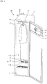
- the clothes treating apparatus 100 in accordance with one embodiment of the present disclosure includes a cabinet 1 defining an exterior design; a clothes-accommodation unit 3 provided in the cabinet 1 and providing a predetermined space for holding clothes or laundry; a mechanical chamber 5 configured to supply at least one of the air or moisture to the clothes-accommodation unit 3; and a pump assembly 7 configured to supply or discharge water.
- the second laundry support part 15 may be provided in the door 11 to allow the clothes located in a state of being spread in the accommodation space 31. In other words, the second laundry support part 15 is fixed to the door 11 as shown in FIG. 1 .
- a hook (H) provided in the hanger 17 may be supported to the second laundry support part 15.
- the mechanical chamber 5 may be provided in a lower area of the accommodation space 31 and partitioned off from the accommodation space 31 by a partition wall. In this instance, a passage is formed to supply the dry air and steam generated in the mechanical chamber 5 to the accommodation space 31.
- the dry air generated in the mechanical chamber 5 may be discharged into the accommodation space 31 via an air outlet hole 35 and the dry air discharged into the accommodation space 31 may contact with the clothes and drawn into the mechanical chamber 5 via an air inlet unit 36.
- the air outlet hole 35 and the air inlet unit 36 may be provided in the partition wall for partition off the space into the accommodation space 31 and the mechanical chamber 5 or a lateral or upper surface of the accommodation space 31 or the door 11.
- the air outlet hole 35 and the air inlet unit 36 may be provided in a bottom surface of the accommodation space 31, in other words, the partition wall but the embodiment is not limited thereto.
- the air inlet unit 36 may be provided in a front area of the bottom surface of the accommodation space 31, in other words, adjacent to the door 11.
- the air inlet unit 36 is provided adjacent to the door 11 and may serve as air curtain. When the door 11 is open and closed, external air will not affect the internal space.
- the air outlet hole 35 may be provided as far from the air inlet unit 36 as possible such that the discharged air can be supplied to the accommodation space 31 uniformly.
- the steam outlet hole 37 may be provided in any areas in the accommodation space 31. It may be provided in the lateral surface of the accommodation space 31 or both of the lateral and bottom surfaces.
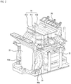
- FIG. 2 illustrates devices that are provided in the mechanical chamber 5.
- the structure of the mechanical chamber may be similar to the structure of a conventional mechanical chamber 5 including a pump 56 configured of a water supply pump 56a and a water discharge pump 56b.
- the air drawn into the heat pump body 513 may sequentially pass through the evaporator 511 and the condenser 512.
- the internal air of the accommodation space 31 has a high humidity or a relatively low temperature because of the mutual action with the clothes.
- the air has the temperature and moisture to become lowered and condensed, while passing the evaporator 511. After that, the air has the temperature to rise again while passing the condenser 512.
- the heat pump 51 may generate dry-and-high-temperature air.
- Each of the pumps 56a and 56b may include an impeller 562 configured to generate flux; a motor 561 configured to rotate the impeller 562; and a flow path pipe 563 in which the impeller 562 is arranged.
- the motor 561 has a motor bracket 565 provided to mount the motor; and a ring 564 provided to absorb a shock between the motor 561 and the motor bracket 565.
- a motor case 566 may be provided in an outer area of the motor.
- the clothes treating apparatus 100 in accordance with the embodiment may perform washing as well as drying, deodorizing and wrinkles-removing.
- the clothes treating apparatus 100 may include a tub provided to hold laundry; a drum rotatably mounted in the tub; and a drive unit configured to rotate the drum.
- FIG. 4 shows only one pump.
- only pump assembly 7 may realize both the water supply and the water discharge.
- the pump assembly 7 has one end connected with a water supply pipe 8 and the other end connected with a water discharge pipe 9.
- the pump assembly 7 includes a motor (72, see FIGS. 5 through 8 ). When the motor is rotated in one direction, the pump assembly 7 may generate flux in the water supply pipe 8. It may generate flux in the water discharge pipe 9 when the motor is rotated in the reverse direction. As describing the conventional pump structure shown in FIG. 3 , the flux or fluidal flow is generated in the passage only when the motor is rotated, regardless of the rotational direction of the motor. On the other hand, the pump assembly 7 in accordance with the embodiment of the present disclosure may effectively perform an independent cycle of each passage based on the direction of the motor 72.
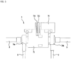
- FIG. 5 illustrates the exterior appearance of the pump assembly 7.
- the pump assembly 7 may include a pump housing 71 defining the pump housing 71; a motor 71; a first passage pipe 78a connected with the water supply pipe 8 and having a first impeller (77a, see FIGS. 6 and 7 ) arranged therein; and a second passage pipe 78b connected with the water discharge pipe 9 and having a second impeller (77b, see FIG. 7 ) arranged therein.
- FIG. 6 is an exploded perspective diagram partially illustrating the pump assembly 7, specifically, the water supply pipe 8.
- the structure of the water discharge pipe 9 is equal to that of the water supply pipe 8 and the internal structure of the pump assembly 7 in the water supply pipe 8 is symmetrical to that of the pump assembly 7 in the water supply pipe 8.
- the connecting arm 76 may include a first connecting arm 76a; and a second connecting arm (76b, see FIG. 8 ).
- the rotational force of the wheel 74 may be transmitted to the clutch 75 by the mutual action between the first and second clutches 75a and 75b.
- the shaft 73 provided in the center of the first clutch 75a in a state of being connected with the first clutch 75a may be rotated and the first impeller 77a connected with the shaft 73 may be then rotated.
- the shaft 73 provided in the center of the second clutch 75b in a state of being connected with the second clutch 75b may be rotated and the second impeller 77b connected with the shaft 73 may be then rotated.
- the shaft 73 connected with the first clutch 75a may be separated from the shaft 73 connected with the second clutch 75b and they may be rotated independently.
- a shaft bearing 731 may be provided in the shaft 73 and the shaft bearing 731 may be located in a pump housing 71 provided between the impeller 77a and 77b and the clutch 75a and 75b. That is to reduce the friction between the pump housing 71 and the shaft when the shaft 73 is rotated.
- the two connecting arms 76a and 76b may be arranged over the first and second wheels 74a and 74b.
- halves of the connecting arms 76a and 76b may be provided in the first wheel 74a and the other halves may be provided in the second wheel 74b.
- the first connecting arm 76a and the second connecting arm 76b may rotate the first clutch 75a, while contacting with the first projections, respectively.
- the rotation of the first clutch 75a may rotate the shaft 73 provided in the first clutch 75a and the rotation of the shaft 73 may rotate the first impeller 77a provided in the first passage pipe 78a.
- the rotation of the first impeller 77a may facilitate the flow passage in the water supply pipe 8.
- the first hands 762a and 762b may include bottom surfaces 766a and 766b; planar surfaces 764a and 764b extended from one ends of the bottom surfaces 766a and 766b; and curved surfaces 765a and 765b extended from the other ends of the bottom surfaces and connected with the ends of the planar surfaces 764a and 764b.
- one end of the planar surface 764b has a length long enough to contact with the first projection 751a.
- one end of the planar surface 764b may have a length long enough to contact with the second projection 751b.
- the bottom surface may contact with the first projection 751a or the second projection 751b. Accordingly, it is preferred that the width of the bottom surface is shorter than the distance between the first projection 751a or the second projection 751b and the connecting bar 761a or 761b.
- the first hand and the second hand may be formed in a similar shape to a shark's fin and have a predetermined thickness.
- the shape is not limited thereto and any shapes may be applicable.
- the first and second hands may have one or more planar surfaces and one or more curved surfaces.
- FIG. 11 illustrates an AA' axis.
- the planar surface 764a or 764b of the first hand 762a or 762b may be positioned in a counter-clock wise direction with respect to the AA' axis, compared with the curved surfaces 765a or 765b.
- FIG. 13 The state of A area (that is, the upper drawing) of FIG. 12 where the first hand 762a or 762b is rotated 90 degrees with respect to the shaft 73 in the clockwise direction is shown in FIG. 13 in a dotted line.
- FIG. 14 illustrates a state where both of the first and second hands are rotated on the shaft 73 180 degrees, compared with FIG. 13 .
- a dotted line of FIG. 14 shows a state where the hands are rotated 90 degrees from the state shown in the dotted line of FIG. 13 and a solid line shows a state where they are rotated 80 degrees from the state shown in the solid line of FIG. 13 .
- the first hand 762a or 762b rotated 90 degrees from the solid line of FIG. 13 is shown in the same shape with the solid line of FIG. 13 .
- the first hand keeps the same shape before being rotated 180 degrees after colliding with the collision surface 7512a. That is equal to the second hand 763a or 763b shown in A' area (a lower drawing).
Landscapes
- Engineering & Computer Science (AREA)
- Textile Engineering (AREA)
- Mechanical Engineering (AREA)
- General Engineering & Computer Science (AREA)
- Power Engineering (AREA)
- Detail Structures Of Washing Machines And Dryers (AREA)
- Structures Of Non-Positive Displacement Pumps (AREA)
Abstract
Description
- The present invention relates to a clothes treating apparatus.
- In general, a clothes treating apparatus is a home appliance configured to perform such diverse treating processes that are related with clothes (e.g., washing, drying, deodorizing, wrinkle-removing and the like). The clothes treating apparatus means a concept including a washing machine for washing clothes, a dryer for drying wet clothes and a refresher for deodorizing the bad smell pervaded in clothes or removing wrinkles of clothes.
- A conventional structure of such a clothes treating apparatus is disclosed in Korean Patent No.
10-2008-0030333 - Meanwhile, the clothes treating apparatuses tend to develop as one device to solve washing, drying, deodorizing and wrinkles-removing. Especially, a water supply system and a water discharge system which are provided in the clothes treating apparatus may require pumps configured to generate flux, respectively. Here, as many functions are combined in one device, the overall volume of the clothes treating apparatus will increase disadvantageously.
- An object of the present invention is to provide a clothes treating apparatus which may perform an independent cycle for each of passages by installing one pump assembly in the passages.
- Another object of the present invention is to provide a clothes treating apparatus which may generate flow of a passage in a water supply pipe or a water discharge pipe according to a rotational direction of a motor.
- A further object of the present invention is to provide a clothes treating apparatus which may reduce an installation space.
- A further object of the present invention is to provide a clothes treating apparatus which may save the cost of materials.
- A further object of the present invention is to provide a clothes treating apparatus which may consume less energy in the driving.
- To achieve these objects and other advantages and in accordance with the purpose of the invention, as embodied and broadly described herein, a clothes treating apparatus comprises a clothes-accommodation unit configured to accommodate clothes or laundry, the clothes treating apparatus comprising: a water supply pipe provided to supply water to the inside of the clothes treating apparatus; a water discharge pipe provided to discharge the water outside from the clothes treating apparatus; and a pump assembly configured to generate flow of the water inside the water supply pipe and the water discharge pipe, using rotation of a motor, wherein the flow of the water is generated only in the water supply pipe or the water discharge pipe based on a rotational direction of the motor. The clothes treating apparatus which may perform an independent cycle for each of passages by installing one pump assembly in the passages. In addition, the clothes treating apparatus may reduce an installation space and save the cost of materials.
- The pump assembly may comprise a wheel that is rotatable by the motor; a pair of clutches provided in both sides of the wheel, respectively, and having the same rotational center with the wheel, the pair of the clutches that are independently rotatable with respect to the wheel; a pair of shafts fixed to rotational centers of the clutches, respectively; an impeller connected with each of the shafts and rotatable according to the rotation of the clutches; and a connecting arm provided in the wheel and configured to transmit a rotational force of the wheel to one of the clutches based on the rotational direction of the motor. The clothes treating apparatus may generate flow of a passage in the water supply pipe or the water discharge pipe according to the rotational direction of the motor.
- The pair of the clutches may comprise a first clutch provided in one side of the wheel; and a second clutch provided in the other side of the wheel, and the connecting arm comprises a first connecting arm and a second connecting arm that are spaced a preset distance apart from the rotational center of the wheel and symmetrically arranged with respect to the rotational center. The clothes treating apparatus may generate flow of a passage in the water supply pipe or the water discharge pipe according to the rotational direction of the motor.
- Each of the connecting arms may comprise a connecting arm rotatably coupled to the wheel and provided in parallel with the shaft; a first hand provided in one end of the connecting bar; and a second hand provided in the other end of the connecting bar, and the first hand rotates the first clutch by contacting with the first clutch, and the second hand rotates the second clutch by contacting with the second clutch. The clothes treating apparatus which may perform an independent cycle for each of passages by installing one pump assembly in the passages. In addition, the clothes treating apparatus may save the energy.
- When the motor is rotated in one direction, the first hand may contact with the first clutch and the second hand may not contact with the second clutch, and when the motor is rotated in the reverse direction, the first hand may not contact with the first clutch and the second hand may contact with the second clutch.
- The first clutch may comprise a first projection projected towards the wheel and contactable with the first hand, and the second clutch may comprise a second projection projected towards the wheel and contactable with the second hand.
- Two first projections may be symmetrically provided with respect to the rotational center of the first clutch, and two second projections may be symmetrically provided with respect to the rotational center of the second clutch. When the rotational direction of the motor is changed, the change of the passage may be performed stably.
- Each of the first and second projections may comprise a contact surface that is contactable with the first hand or the second hand; and a collision surface provided to collide with the first hand or the second hand. When the rotational direction of the motor is changed, the change of the passage may be performed stably.
- The contact surface may have a larger area than the collision surface. The change of the passage may be performed stably.
- The first hand and the second hand may be perpendicular with each other with respect to one of the connecting arms. The structure may be the optimal structure for the efficient passage change.
- Each of the first and second hands may comprise a planar surface provided in a predetermined area and a curved surface provided in the other area. That is necessary in the passage change.
- When the wheel is rotated in one direction, the planar surfaces of the first hands may contact with the contact surfaces of the first projections, respectively, and the second hands may not contact with the second projections.
- When the wheel is rotated in the reverse direction, the planar surfaces of the second hands may contact with the contact surfaces of the second projections and the first hands may not contact with the first projections.
- When the wheel is rotated in the reverse direction after rotated in one direction for a preset time period, the curved surfaces of the first hands may collide with the collision surfaces of the first projections and the connecting bars may be then rotated.
- The rotation of the connecting bars may facilitate contact between the planar surfaces of the second hands and the contact surfaces of the second projections, and the first hands may not contact with the first projections.
- The clothes treating apparatus may further comprise a steam supply device configured to supply steam to the clothes-accommodation unit; and a heat pump configured to generate hot air.
- The impeller may comprise a first impeller connected with the water supply pipe; and a second impeller connected with the water discharge pipe, and the first impeller and the second impeller may not be rotated at the same time.
- A pump assembly configured to generate flow of water inside a water supply pipe and a water discharge pipe that are provided in a clothes treating apparatus, using rotation of a motor, the pump assembly comprises: a first passage pipe connected with the water supply pipe; a second passage pipe connected with the water discharge pipe, wherein flow of water is generated only in the first passage pipe or the second passage pipe based on a rotational direction of the motor. The clothes treating apparatus which may perform an independent cycle for each of passages by installing one pump assembly in the passages. In addition, the clothes treating apparatus may reduce an installation space and save the cost of materials.
- The pump assembly may further comprise a wheel that is rotatable by the motor; a pair of clutches provided in both sides of the wheel, respectively, and having the same rotational center with the wheel, the pair of the clutches that are independently rotatable with respect to the wheel; a pair of shafts fixed to rotational centers of the clutches, respectively; an impeller connected with each of the shafts and rotatable according to the rotation of the clutches; and a connecting arm provided in the wheel and configured to transmit a rotational force of the wheel to one of the clutches based on the rotational direction of the motor.
- The pair of the clutches may comprise a first clutch provided in one side of the wheel; and a second clutch provided in the other side of the wheel, and the connecting arm comprises a first connecting arm and a second connecting arm that are spaced a preset distance apart from the rotational center of the wheel and symmetrically arranged with respect to the rotational center.
- As is apparent from the above description, the present disclosure has the effect of providing a clothes treating apparatus which may perform an independent cycle for each of passages by installing one pump assembly in the passages.
- In addition, the present disclosure has the effect of providing a clothes treating apparatus which may generate flow of a passage in a water supply pipe or a water discharge pipe according to a rotational direction of a motor.
- In addition, the present disclosure has the effect of providing a clothes treating apparatus which may reduce an installation space.
- In addition, the present disclosure has the effect of providing a clothes treating apparatus which may save the cost of materials.
- In addition, the present disclosure has the effect of providing a clothes treating apparatus which may consume less energy in the driving
-
-
FIG. 1 is a perspective diagram of a clothes treating apparatus in accordance with one embodiment of the present disclosure; -
FIG. 2 is a diagram illustrating a conventional structure of a mechanical chamber provided in the clothes treating apparatus; -
FIG. 3 is a diagram illustrating a conventional structure of a pump assembly provided in the mechanical chamber; and -
FIG. 4 is a diagram illustrating a structure of a mechanical chamber provided in the clothes treating apparatus in accordance with one embodiment of the present disclosure; -
FIG. 5 is a diagram illustrating an exterior design of a pump assembly in accordance with one embodiment; -
FIG. 6 is a an exploded perspective diagram partially illustrating the pump assembly in accordance with the embodiment; -
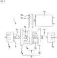
FIG. 7 is a diagram illustrating the inside of the pump assembly in accordance with the embodiment; -
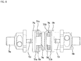
FIG. 8 is a bottom view illustrating the pump assembly ofFIG. 7 in accordance with the embodiment; -
FIG. 9 is a perspective diagram of the pump assembly, specifically, one example of an operation when a motor is rotated in one direction; -
FIG. 10 is a perspective diagram of the pump assembly, specifically, one example of an operation when a motor is rotated in the reverse direction; -
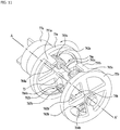
FIG. 11 is a perspective diagram of the pump assembly in accordance with the embodiment, specifically, illustrating some components to describe one example of an operation when the motor is rotated in one direction; -
FIG. 12 is a sectional diagram illustrating one example of an example of an operation when the pump assembly in accordance with the embodiment is rotated in one direction; -
FIG. 13 is a sectional diagram illustrating one example of an operation when the pump assembly in accordance with the embodiment is rotated in one direction, specifically, a state after a preset time period, compared withFIG. 12 ; and -
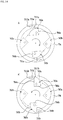
FIG. 14 is a sectional diagram illustrating one example of an operation when the pump assembly in accordance with the embodiment is rotated in one direction, specifically, a state after a preset time period, compared withFIG. 13 . - Reference will now be made in detail to the preferred embodiments of the present invention, examples of which are illustrated in the accompanying drawings. It should be noted herein that construction of an apparatus, which will hereinafter be described, and a control method of the apparatus are given only for illustrative purposes and the protection scope of the invention is not limited thereto. Wherever possible, the same reference numbers will be used throughout the drawings to refer to the same or like parts.
- As shown in
FIG. 1 , theclothes treating apparatus 100 in accordance with one embodiment of the present disclosure includes a cabinet 1 defining an exterior design; a clothes-accommodation unit 3 provided in the cabinet 1 and providing a predetermined space for holding clothes or laundry; amechanical chamber 5 configured to supply at least one of the air or moisture to the clothes-accommodation unit 3; and apump assembly 7 configured to supply or discharge water. - A predetermined space (hereinafter, an accommodation space 31) may be defined in the clothes-
accommodation unit 3 to accommodate clothes or laundry and theaccommodation space 31 may be open and closed by adoor 11 provided in the cabinet 1. - A laundry support unit may be further provided in the cabinet 1 to support the clothes or laundry. The laundry support unit may include a first
laundry support part 13 provided in theaccommodation space 31; and a secondlaundry support part 15 provided in thedoor 11. - The first
laundry support part 13 may be provided in a bar shape provided along a depth direction of the accommodation space 31 (a direction of X-axis) width direction of the accommodation space (a direction of Y-axis or a width direction of the door).FIG. 1 illustrates one example of thefirst laundry part 13 that is provided along the width direction of theaccommodation space 31. - In this instance, clothes may be supported by a hook (H) of a
hanger 17 provided in the firstlaundry support part 13 or they may be supported in the firstlaundry support part 13 without thehanger 17. In any cases, clothes may be kept spread and unfolded in theaccommodation space 31. - The second
laundry support part 15 may be provided in thedoor 11 to allow the clothes located in a state of being spread in theaccommodation space 31. In other words, the secondlaundry support part 15 is fixed to thedoor 11 as shown inFIG. 1 . A hook (H) provided in thehanger 17 may be supported to the secondlaundry support part 15. - The
mechanical chamber 5 may be provided in a lower area of theaccommodation space 31 and partitioned off from theaccommodation space 31 by a partition wall. In this instance, a passage is formed to supply the dry air and steam generated in themechanical chamber 5 to theaccommodation space 31. - The dry air generated in the
mechanical chamber 5 may be discharged into theaccommodation space 31 via anair outlet hole 35 and the dry air discharged into theaccommodation space 31 may contact with the clothes and drawn into themechanical chamber 5 via anair inlet unit 36. - The
air outlet hole 35 and theair inlet unit 36 may be provided in the partition wall for partition off the space into theaccommodation space 31 and themechanical chamber 5 or a lateral or upper surface of theaccommodation space 31 or thedoor 11. InFIG. 1 , theair outlet hole 35 and theair inlet unit 36 may be provided in a bottom surface of theaccommodation space 31, in other words, the partition wall but the embodiment is not limited thereto. - In this embodiment, the
air inlet unit 36 may be provided in a front area of the bottom surface of theaccommodation space 31, in other words, adjacent to thedoor 11. Theair inlet unit 36 is provided adjacent to thedoor 11 and may serve as air curtain. When thedoor 11 is open and closed, external air will not affect the internal space. Theair outlet hole 35 may be provided as far from theair inlet unit 36 as possible such that the discharged air can be supplied to theaccommodation space 31 uniformly. - A
steam outlet hole 37 may be further provided in the lower area of theaccommodation space 31. The steam generated in a steam generator (52, seeFIG. 2 ) provided in themechanical chamber 5 may be supplied to the clothes held in theaccommodation space 31 via thesteam outlet hole 37. - The
steam outlet hole 37 may be provided in any areas in theaccommodation space 31. It may be provided in the lateral surface of theaccommodation space 31 or both of the lateral and bottom surfaces. -
FIG. 2 illustrates devices that are provided in themechanical chamber 5. The structure of the mechanical chamber may be similar to the structure of a conventionalmechanical chamber 5 including apump 56 configured of awater supply pump 56a and awater discharge pump 56b. - In the
mechanical chamber 5 may be provided aheat pump 51 configured to generate dry air by lowering the humidity and temperature of the air; asteam generator 52 configured to generate the steam which will be supplied to theaccommodation space 31; afirst duct 53 provided in the lower area of theaccommodation space 31 and communicable with theair inlet unit 36; and a second duct provided in the lower area of theaccommodation space 31 and communicable with theair outlet hole 35, having theheat pump 51 therein. Thefirst duct 53 and thesecond duct 54 may be in communication with each other. The flow of the air may be facilitated by the actuation of thefan 55 provided in themechanical chamber 5. - When describing the flow of the air, the internal air of the
accommodation space 31 may be drawn into thefirst duct 53 via theair inlet unit 36 and then drawn into thesecond duct 54 from thefirst duct 53 to pass through theheat pump 51. After passing through theheat pump 51, the air may be discharged into theaccommodation space 31 via theair outlet hole 35 again. - The
heat pump 51 may be provided in aheat pump body 513 provided in thesecond duct 54. Anevaporator 511 and acondenser 512 may be sequentially installed in theheat pump body 513. - The
evaporator 511 is the device configured to pass a low-temperature liquid refrigerant there through and lower the temperature by sucking heat from latent air. Thecondenser 512 is the device configured to pass a high-temperature gas refrigerant there through and raise the temperature of the latent air. - The air drawn into the
heat pump body 513 may sequentially pass through theevaporator 511 and thecondenser 512. The internal air of theaccommodation space 31 has a high humidity or a relatively low temperature because of the mutual action with the clothes. The air has the temperature and moisture to become lowered and condensed, while passing theevaporator 511. After that, the air has the temperature to rise again while passing thecondenser 512. Specifically, theheat pump 51 may generate dry-and-high-temperature air. - Meanwhile, the
pump 56 may be further provided in themechanical chamber 5. Thepump 56 may include thewater supply pump 56a configured to supply moisture to the inside of theclothes treating apparatus 100; and thewater discharge pump 56b configured to discharge water to the inside of theclothes treating apparatus 100. - Specific structures of the pumps are shown in
FIG. 3 . Each of thepumps impeller 562 configured to generate flux; amotor 561 configured to rotate theimpeller 562; and aflow path pipe 563 in which theimpeller 562 is arranged. Themotor 561 has amotor bracket 565 provided to mount the motor; and aring 564 provided to absorb a shock between themotor 561 and themotor bracket 565. To protect themotor 561 mounted in themotor bracket 564, amotor case 566 may be provided in an outer area of the motor. When themotor 561 rotates, theimpeller 562 may be rotated and the rotation of theimpeller 562 may facilitate the water supply and discharge. Only when theimpeller 562 is rotated, the flux may occur. Accordingly, the motor may rotate in any directions. - Meanwhile, the
clothes treating apparatus 100 in accordance with the embodiment may perform washing as well as drying, deodorizing and wrinkles-removing. In other words. For the washing, theclothes treating apparatus 100 may include a tub provided to hold laundry; a drum rotatably mounted in the tub; and a drive unit configured to rotate the drum. - Specifically, the embodiment of the present disclosure may be applied to any types of the
clothes treating apparatuses 100 having the water supply and discharge applied thereto.FIG. 4 illustrates thepump assembly 7 provided in themechanical chamber 5 in accordance with one embodiment of the present disclosure. However, the embodiment shown inFIG. 4 is one of examples and thepump assembly 7 may be separated from themechanical chamber 5 as the independent part or in one of the other areas. As described above, thepump assembly 7 may be applied to theclothes treating apparatus 100 requiring the water supply and discharge system. -
FIG. 4 illustrates that thepump assembly 7 in accordance with the embodiment is provided in themechanical chamber 5. The conventional components provided in the mechanical chamber 4 are equal to those that are shown inFIG. 2 and only different features from the embodiment shown inFIG. 2 will be described accordingly. - Different from
FIG. 2 ,FIG. 4 shows only one pump. In other words, only pumpassembly 7 may realize both the water supply and the water discharge. Thepump assembly 7 has one end connected with awater supply pipe 8 and the other end connected with awater discharge pipe 9. - The
pump assembly 7 includes a motor (72, seeFIGS. 5 through 8 ). When the motor is rotated in one direction, thepump assembly 7 may generate flux in thewater supply pipe 8. It may generate flux in thewater discharge pipe 9 when the motor is rotated in the reverse direction. As describing the conventional pump structure shown inFIG. 3 , the flux or fluidal flow is generated in the passage only when the motor is rotated, regardless of the rotational direction of the motor. On the other hand, thepump assembly 7 in accordance with the embodiment of the present disclosure may effectively perform an independent cycle of each passage based on the direction of themotor 72. - The specific structure of the
pump assembly 7 will be described, referring toFIGS. 5 through 8. FIGS. 5 through 8 illustrate only thepump assembly 7 separately and include a front view, an exploded view and a top view. -
FIG. 5 illustrates the exterior appearance of thepump assembly 7. Referring toFIG. 5 , thepump assembly 7 may include apump housing 71 defining thepump housing 71; amotor 71; afirst passage pipe 78a connected with thewater supply pipe 8 and having a first impeller (77a, seeFIGS. 6 and7 ) arranged therein; and asecond passage pipe 78b connected with thewater discharge pipe 9 and having a second impeller (77b, seeFIG. 7 ) arranged therein. - The rotational force of the
motor 72 may be transmitted to a drivepulley 721 and abelt 722 connected with thedrive pulley 721 may transmit the rotational force to a wheel (74, seeFIGS. 6 and7 ). - The internal configuration of the
pump housing 71 will be described, referring toFIG. 6 and7 . -
FIG. 6 is an exploded perspective diagram partially illustrating thepump assembly 7, specifically, thewater supply pipe 8. The structure of thewater discharge pipe 9 is equal to that of thewater supply pipe 8 and the internal structure of thepump assembly 7 in thewater supply pipe 8 is symmetrical to that of thepump assembly 7 in thewater supply pipe 8. - The rotational force of the
motor 72 may be transmitted to thewheel 74 via thedrive pulley 721 and thebelt 722. Thewheel 74 may include afirst wheel 74a provided closer to thewater supply pipe 8 and a second wheel (74b, seeFIG. 7 ) provided closer to thewater discharge 9. The first andsecond wheels belt 722 may be supplied to thewheels - The
pump assembly 7 may further include a clutch 75 configured to be supplied the rotational force of thewheels first wheel 74a; and a second clutch 75b provided adjacent to thesecond wheel 74b. - The clutch 75 may receive the rotational force of the
wheel 74 via a connecting arm 76. The example of the operation configured to transmit the rotational force of thewheel 74 to the clutch 75 via the connecting arm 76 will be described later. - The connecting arm 76 may include a first connecting
arm 76a; and a second connecting arm (76b, seeFIG. 8 ). The rotational force of thewheel 74 may be transmitted to the clutch 75 by the mutual action between the first andsecond clutches - Meanwhile, the clutch 75a and 75b receiving the rotational force from the connecting
arm impeller shaft 73 via theshaft 73. - Once the first clutch 75a is rotated, the
shaft 73 provided in the center of the first clutch 75a in a state of being connected with the first clutch 75a may be rotated and thefirst impeller 77a connected with theshaft 73 may be then rotated. Also, once the second clutch 75b is rotated, theshaft 73 provided in the center of the second clutch 75b in a state of being connected with the second clutch 75b may be rotated and thesecond impeller 77b connected with theshaft 73 may be then rotated. Theshaft 73 connected with the first clutch 75a may be separated from theshaft 73 connected with the second clutch 75b and they may be rotated independently. - A
shaft bearing 731 may be provided in theshaft 73 and the shaft bearing 731 may be located in apump housing 71 provided between theimpeller pump housing 71 and the shaft when theshaft 73 is rotated. - Meanwhile, a
motor bracket 723 may be further provided in an outer area of themotor 72 to protect themotor 72. -
FIG. 7 is a front view illustrating the inside of thepump assembly 7, except thepump housing 71, which is corresponding to a state where all of the components are assembled. - When the
motor 72 is rotated in one direction, thewheel belt 722 having received the rotational force of themotor 72. Thefirst wheel 74a and thesecond wheel 74b are fixedly coupled to each other to form one body such that they may be rotary in the same direction when being rotated. - A connecting arm 76 may be rotatably coupled to the
wheel FIG. 8 , the first connectingarm 76a and the second connectingarm 76b may be spaced a preset distance apart from the center of thewheel 74. The first connectingarm 76a and the second connectingarm 76b may be symmetrically arranged with respect to the center of thewheel 74. - The two connecting
arms second wheels arms first wheel 74a and the other halves may be provided in thesecond wheel 74b. - The connecting
arms wheel 74. The rotation of the connectingarm motor 72 is rotated in one direction, the first connectingarm 76a and the second connectingarm 76b may rotate the first clutch 75a by the contact with the first clutch 75a. When themotor 72 is rotated in the reverse direction, the first connectingarm 76a and the second connecting arm may rotate the second clutch 75b by the contact with the second clutch 75b. - Specifically, since the connecting
arms arm -
FIG. 8 is a bottom view ofFIG. 7 , viewed from the bottom, and illustrates both of the first and second connectingarms arms wheel 74, respectively. The distances between the connecting arms and the center of thewheel 74 are the same. - The first clutch 75a may include a
first projection 751a and the second clutch 75b may include a second projection to transmit the rotational force to the connectingarms second projections 751 and 751b may become the means for the contact of the clutches with the connectingarms - Each of the first and
second projections first projections 751a may be projected towards the second clutch 75b, in parallel with the rotational direction of the first clutch 75a. The twofirst projections 751a may be symmetrically arranged with respect to the rotational center of the first clutch 75a. Accordingly, a virtual line between the twofirst projections 751a may pass the rotational center of the first clutch 75a. Meanwhile, thefirst projections 751a may be provided in an edge area of the first clutch 75a. - The
second projections 751b may be projected towards the first clutch 75a, in parallel with the rotational direction of the second clutch 75b. The twosecond projections 751b may be symmetrically arranged with respect to the rotational center of the second clutch 75b. Accordingly, a virtual line between the twosecond projections 751b may pass the rotational center of the second clutch 75b. Meanwhile, thesecond projections 751b may be provided in an edge area of the second clutch 75b. -
FIG. 8 illustrates a state where a liquid flows in thewater supply pipe 8. The rotation of the motor in one direction may rotate thewheel arm 76a and the second connectingarm 76b provided in thewheels first projections 751a provided in the first clutch 75a. - The first connecting
arm 76a and the second connectingarm 76b may rotate the first clutch 75a, while contacting with the first projections, respectively. The rotation of the first clutch 75a may rotate theshaft 73 provided in the first clutch 75a and the rotation of theshaft 73 may rotate thefirst impeller 77a provided in thefirst passage pipe 78a. The rotation of thefirst impeller 77a may facilitate the flow passage in thewater supply pipe 8. - At this time, as the first and second connecting
arms second projections 751b, the second clutch 75b will not be rotated. As thesecond impeller 77b is not rotated, no liquid will flow in thewater discharge pipe 9. - If a liquid is intended to flow in the
water discharge pipe 9, the rotational direction is changed into the reverse direction. If the rotational direction of themotor 72 is changed, the first and second connectingarms - When the first and second connecting
arms second projections 751b, respectively, the second clutch 75b may be rotated. The rotation of the second clutch 75b may rotate theshaft 73 provided in the second clutch 75b and the rotation of theshaft 73 may rotate thesecond impeller 77b provided in thesecond passage pipe 78b. The rotation of thesecond impeller 77b may facilitate the flow passage in thewater discharge pipe 9. - At this time, as the first and second connecting
arms first projections 751a, the first clutch 75a will not be rotated. As thefirst impeller 77a is not rotated, no liquid will flow in thewater supply pipe 8. - Referring to
FIGS. 9 through 11 , the specific structure of the connecting arm 76 and the mutual action between the connectingarms projections -
FIG. 9 is a perspective diagram ofFIG. 8 , viewed from a different angle, andFIG. 10 is a perspective diagram illustrating a state where only the rotational direction is changed.FIG. 11 is a diagram to describe the mutual action between the connectingarms projections - Referring to
FIG. 11 , the specific structure of the connecting arms will be described first. The connecting arms 76 may include the first connectingarm 76a and the second connectingarm 76b and the first and second connectingarms arm 76a and the second connectingarm 76b may be arranged in symmetrical positions with respect to the rotational axis of thewheel 74. - The first connecting
arm 76a may include a connectingbar 761a rotatably provided in the wheel, in parallel with theshaft 73; afirst hand 762a provided in one end of the connectingbar 761a and configured to mutually actuate with thefirst projection 751a; and asecond hand 763a provided in the other end of the connectingbar 761a and configured to mutually actuate with thesecond projection 751b. - The second
connecting arm 76b may include a connectingbar 761b rotatably provided in thewheel 74, in parallel with theshaft 73; afirst hand 762b provided in one end of the connectingbar 761b and configured to mutually actuate with thefirst projection 751a; and asecond hand 763b provided in the other end of the connectingbar 761b and configured to mutually actuate with thesecond projection 751b. - The
first hands second hands shaft 73. The thickness of thefirst hands second hands planar surfaces curved surfaces planar surfaces curved surfaces FIGS. 12 through 14 . - In one embodiment shown in
FIGS. 12 through 14 , thefirst hands bottom surfaces planar surfaces bottom surfaces curved surfaces planar surfaces - The connecting
bars shaft 73 than the first andsecond projections bottom surface 766a of thefirst hand 762a is directed towards theshaft 73, the end of theplanar surface 764a has to have a length enough to contact with thefirst projection 751a. When abottom surface 766a of thesecond hand 763a is directed towards the shaft, one end of theplanar surface 764a has to have a length enough to contact with thesecond projection 751b. - Similarly, when the
bottom surface 766b of thefirst hand 762b is directed towards theshaft 73, one end of theplanar surface 764b has a length long enough to contact with thefirst projection 751a. When thebottom surface 766b of thesecond hand 763b is directed towards theshaft 73, one end of theplanar surface 764b may have a length long enough to contact with thesecond projection 751b. - The width of the
bottom surface bar first projection 751a or thesecond projection 751b. Unless thefirst hand first projection 751a, one end of thebottom surface shaft 73. Unless thesecond hand second projection 751b, one end of thebottom surface shaft 73. - At this time, when the length of the bottom surface is longer than the distance between the connecting
bar first projection 751a or thesecond projection 751b, the bottom surface may contact with thefirst projection 751a or thesecond projection 751b. Accordingly, it is preferred that the width of the bottom surface is shorter than the distance between thefirst projection 751a or thesecond projection 751b and the connectingbar - The end of the
bottom surface bar first projection 751a or thesecond projection 751b, when it is the farthest from theshaft 73. - The first hand and the second hand according to one embodiment of the present disclosure may be formed in a similar shape to a shark's fin and have a predetermined thickness. However, the shape is not limited thereto and any shapes may be applicable. The first and second hands may have one or more planar surfaces and one or more curved surfaces.
- Meanwhile, the
first hand 762a and thesecond hand 763a that are provided in the first connectingarm 76a may be perpendicular with a virtual line having thebottom surfaces 766a and also perpendicular with a virtual extended line having theplanar surfaces 764a. Accordingly, when thefirst hand 762a contacts with thefirst projection 751a, thesecond hand 763a may be perpendicular with thefirst hand 762a. As thebottom surface 766a is positioned between theshaft 73 and thesecond projection 751b, thesecond hand 763a may not contact with thesecond projection 751b. In other words, the end of thebottom surface 766a (that is positioned farthest from the shaft 73) may not contact with thesecond projection 751b. In contrast, when thesecond projection 751b contacts with thesecond hand 763a, thefirst projection 751a and thefirst hand 762a may not contact with each other. - Like the second connecting
arm 76a, virtual extended surfaces having thebottom surfaces 766b may be perpendicular with each other in thefirst hand 762b and thesecond hand 763b provided in the second connectingarm 76b, respectively. Virtual extended surfaces having theplanar surfaces 764b may be also perpendicular with each other. Accordingly, when thefirst hand 762b contacts with thefirst projection 751a, thesecond hand 763b may be perpendicular with thefirst hand 762b. As thebottom surface 766b is positioned between theshaft 73 and thesecond projection 751b, thesecond hand 763b may not contact with thesecond projection 751b. In other words, the end of thebottom surface 766b (that is positioned farthest from the shaft 73) may not contact with thesecond projection 751b. In contrast, when thesecond projection 751b contacts with thesecond hand 763b, thefirst projection 751a and thefirst hand 762b may not contact with each other. -
FIG. 11 illustrates an AA' axis. When viewing A from A' in a state where thebottom surface 766a is directed towards theshaft 73, theplanar surface first hand curved surfaces - When viewing A from A' in a state where the
bottom surface 766b is directed towards theshaft 73, theplanar surface second hand curved surfaces - When the
wheel 74 is rotated in the counter-clockwise direction with respect to the view of A from A' along the AA' axis as shown inFIG. 11 , theplanar surface 764a of thefirst hand 762a and theplanar surface 764b of thefirst hand 762b may contact with thefirst projections 751a, respectively. - When the
wheel 74 is rotated in the clockwise direction in the state ofFIG. 11 , theplanar surface 764a of thefirst hand 762a may be released from the contact with thefirst projection 751a and thecurved surface 765a of thefirst hand 762a may be collided with thefirst projection 751a. The connectingbar 761a may be rotated by the collision. As thefirst hand 762a and thesecond hand 763a are perpendicular with each other, the planar surface of thesecond hand 763a may contact with thesecond projection 751b. In other words, the second clutch 75b may be rotated. Thefirst hand 762b of the second connectingarm 76b may perform the same operation with thefirst hand 762a and thesecond hand 763b may perform the same operation with thesecond hand 763a. In brief, thesecond hand second projections 751b, respectively, and the second clutch 75b may be rotated by the contact. -
FIGS. 9 and10 are diagrams illustrating thewheels FIG. 9 illustrates a state where the wheel is rotated in the counter-clockwise direction andFIG. 10 illustrates a state where the wheel is rotated in the clockwise direction. -
FIG. 9 shows that theplanar surface 764a of thefirst hand 762a rotates the first clutch 75a while contacting with thefirst projection 751a. InFIG. 10 having the reversed rotational direction, thecurved surface 765a of thefirst hand 762a rotates the connectingbar 761a while colliding with thefirst projection 751a. Accordingly, theplanar surface 764a of thesecond hand 763a may rotate the second clutch 75b while contacting with thesecond projection 751b. -
FIGS. 12 through 14 illustrate the mutual action between the connecting arm 76 and theprojections FIG. 11 , the mutual action between the first clutch 75a and thefirst hand second hand FIG. 11 is shown in the upper area ofFIG. 12 and the device in the region A' along the AA' axis is shown in the lower area ofFIG. 12 . - Referring to
FIG. 12 , the specific structure of the first andsecond projections - The
first projection 751a includes acontact surface 7511a corresponding to a surface contacting with theplanar surface first hand collision surface 7512a corresponding to a surface colliding with thecurved surface first hand - The
contact surface 7511a has a larger area than thecollision surface 7512a. That is to transmit the rotational force to the first clutch 75a from theplanar surface 764a or 764 of thefirst hand - In contrast, the
collision surface 7512a may have a small area. That is to rotate the connectingbar 761a by applying a strong shock to thecurved surface first hand curved surface collision surface 7512a is curved such that friction with thecollision surface 7512a may occur, which is shown inFIG. 13 specifically. - The
first projection 751a includes acontact surface 7511b corresponding to a surface contacting with theplanar surface second hand collision surface 7512b corresponding to a surface colliding with thecurved surface second hand - The
contact surface 7511b has a larger area than thecollision surface 7512b. That is to transmit the rotational force to the second clutch 75b from theplanar surface 764a or 764 of thesecond hand - In contrast, the
collision surface 7512b may have a small area. That is to rotate the connectingbar 761b by applying a strong shock to thecurved surface second hand curved surface collision surface 7512b is curved such that friction with thecollision surface 7512b may occur, which is shown inFIG. 13 specifically. -
FIG. 12 illustrates that thewheel 74 is rotated in the counter-clockwise direction, viewed from A' towards A with respect to the AA' axis likeFIGS. 9 and11 . An upper drawing and a lower drawing show that the rotational directions are reversed. That is a difference whether the direction of view is from A' towards A or from A towards A' but the wheel is substantially rotated in the same direction. - Referring to the drawing towards A, the
first hand contact surface 7511a of thefirst projection 751a and it is shown that the rotational force of thewheel 74 is transmitted to the first clutch 75a via thefirst hand first projection 751a. - Referring to the drawing towards A', the
second hand second projection 751b. Thefirst hand 762a and thesecond hand 763a are perpendicular with each other. Accordingly, only when thewheel 74 is continuously rotated in the counter-clockwise direction, viewed from A' towards A shown inFIG. 12 , the rotational force of thewheel 74 may be transmitted only to the first clutch 75a. - Compared with
FIG. 12 ,FIG. 13 shows a state where the rotational direction of thewheel 74 is changed into the clockwise direction with respect to the AA' direction from A' towards A. - The state of A area (that is, the upper drawing) of
FIG. 12 where thefirst hand shaft 73 in the clockwise direction is shown inFIG. 13 in a dotted line. The state where the wheel is rotated 90 degrees again is shown in a solid line. - Right after the rotational direction of the
wheel 74 is changed, the connectingbar 761a will not be rotated until thecurved surface collision surface 7512a. However, when theplanar surface contact surface 7511a provided in thefirst projection 751a and rotated 180 degrees with respect to theshaft 73, thecollision surface 7512a provided in thefirst projection 751a and thecurved surface - As shown in the upper drawing of
FIG. 13 , the connectingbar 761a may be rotated by the collision and thefirst hand second hand 763a connected with thefirst hand 762a and thesecond hand 763b connected with thefirst hand 762b may be rotated as much as the first hand is rotated a preset angle. - The
second hand FIG. 13 (the lower drawing) may continuously keep a non-contact state with thesecond projection 751b. The state where the second hand is rotated 90 degrees with respect to theshaft 73 in the clockwise direction is shown in a dotted line ofFIG. 13 . The state where the wheel is rotated 90 degrees again is shown in a solid line. That reason why the second hand shown in the solid line is rotated a preset angle is that the first hand is collided with thecollision surface 7512a of the first projection. - The rotation of the first hand may rotate the connecting
bars shaft 73, the second hand is in a state shown in a lower drawing ofFIG. 13 . -
FIG. 14 illustrates a state where both of the first and second hands are rotated on theshaft 73 180 degrees, compared withFIG. 13 . A dotted line ofFIG. 14 shows a state where the hands are rotated 90 degrees from the state shown in the dotted line ofFIG. 13 and a solid line shows a state where they are rotated 80 degrees from the state shown in the solid line ofFIG. 13 . - Referring to A area of
FIG. 14 (an upper drawing ofFIG. 14 ), thefirst hand FIG. 13 is shown in the same shape with the solid line ofFIG. 13 . InFIG. 13 . The first hand keeps the same shape before being rotated 180 degrees after colliding with thecollision surface 7512a. That is equal to thesecond hand - Meanwhile, when the
wheel 74 is rotated 90 degrees more as shown in A area ofFIG. 14 in a solid line from a dotted line, the connectingbar 761a may be rotated a preset angle more. In other words, the final position of the first hand in A area drawing is equal to the initial position of the second hand shown inFIG. 12 . - The reason why the rotation shown in A area of
FIG. 14 will be described referring to A' area ofFIG. 14 . - When the second hand is rotated 90 degrees from the state shown in a solid line corresponding to the final position in A' area of
FIG. 13 , the position is changed into a position shown in a dotted line of A' area ofFIG. 14 . In this instance, when it is rotated 90 degrees more, the position is changed into a position shown in a solid line of A' area ofFIG. 14 . At this time, a point at which theplanar surface curved surface contact surface 7511b of thesecond projection 751b. Specifically, inFIG. 13 , the rotation of the connectingbar contact surface 7511a of the second projection. - When the second hand is continuously rotated, the
planar surface contact surface 7511b of the second projection. In other words, the second hand shown in A' area ofFIG. 14 is located at the same position with the position of the first hand shown inFIG. 12 . - In brief, the change of the rotational direction may facilitate the contact between the
planar surface contact surface 7511b of the second projection. The rotational force of thewheel 74 may be transmitted to the second clutch 75b via the second hand. In contrast, the first hand may not contact with the first projection and the first clutch 75a may not be rotated. - When the rotational direction of the
wheel 74 is changed again from the final state ofFIG. 14 , the first and second hands are rotated in the same mechanism with the operation described referring toFIGS. 12 through 14 . Accordingly, the first hand may rotate thefirst projection 751a and the second hand may not contact with thesecond projection 751b. - Specifically, only the liquid inside the
water supply pipe 8 or thewater discharge pipe 9 may flow based on the rotational direction of themotor 72. The independent cycle of each passage is performed by only changing the rotational direction of themotor 72. Accordingly, compared with the conventional clothes treating apparatus using the two pumps (including even the two motors), the energy may be saved. Only onemotor 72 may be used and that is advantageous in utilizing the overall space of the clothes treating apparatus. Also, only onemotor 72 may be used and the material cost may be saved advantageously. - It will be apparent to those skilled in the art that various modifications and variations can be made in the present disclosure without departing from the spirit or scope of the disclosures. Thus, it is intended that the present disclosure covers the modifications and variations of this disclosure provided they come within the scope of the appended claims and their equivalents.
Claims (20)
- A clothes treating apparatus comprising a clothes-accommodation unit configured to accommodate clothes or laundry, the clothes treating apparatus comprising:a water supply pipe provided to supply water to the inside of the clothes treating apparatus;a water discharge pipe provided to discharge the water outside from the clothes treating apparatus; anda pump assembly configured to generate flow of the water inside the water supply pipe and the water discharge pipe, using rotation of a motor,wherein the flow of the water is generated only in the water supply pipe or the water discharge pipe based on a rotational direction of the motor.
- The clothes treating apparatus of claim 1, wherein the pump assembly comprises,
a wheel that is rotatable by the motor;
a pair of clutches provided in both sides of the wheel, respectively, and having the same rotational center with the wheel, the pair of the clutches that are independently rotatable with respect to the wheel;
a pair of shafts fixed to rotational centers of the clutches, respectively;
an impeller connected with each of the shafts and rotatable according to the rotation of the clutches; and
a connecting part provided in the wheel and configured to transmit a rotational force of the wheel to one of the clutches based on the rotational direction of the motor. - The clothes treating apparatus of claim 2, wherein the pair of the clutches comprises,
a first clutch provided in one side of the wheel; and
a second clutch provided in the other side of the wheel, and
the connecting arm comprises a first connecting arm and a second connecting arm that are spaced a preset distance apart from the rotational center of the wheel and symmetrically arranged with respect to the rotational center. - The clothes treating apparatus of claim 3, wherein each of the connecting arms comprises,
a connecting arm rotatably coupled to the wheel and provided in parallel with the shaft;
a first hand provided in one end of the connecting bar; and
a second hand provided in the other end of the connecting bar, and
the first hand rotates the first clutch by contacting with the first clutch, and the second hand rotates the second clutch by contacting with the second clutch. - The clothes treating apparatus of claim 4, wherein when the motor is rotated in one direction, the first hand contacts with the first clutch and the second hand does not contact with the second clutch, and
when the motor is rotated in the reverse direction, the first hand does not contact with the first clutch and the second hand contacts with the second clutch. - The clothes treating apparatus of claim 4, wherein the first clutch comprises a first projection projected towards the wheel and contactable with the first hand, and
the second clutch comprises a second projection projected towards the wheel and contactable with the second hand. - The clothes treating apparatus of claim 6 wherein two first projections are symmetrically provided with respect to the rotational center of the first clutch, and two second projections are symmetrically provided with respect to the rotational center of the second clutch.
- The clothes treating apparatus of claim 6, wherein each of the first and second projections comprises,
a contact surface that is contactable with the first hand or the second hand; and
a collision surface provided to collide with the first hand or the second hand. - The clothes treating apparatus of claim 8 wherein the contact surface has a larger area than the collision surface.
- The clothes treating apparatus of claim 8, wherein the first hand and the second hand are perpendicular with each other with respect to one of the connecting arms.
- The clothes treating apparatus of claim 10, wherein each of the first and second hands comprises a planar surface provided in a predetermined area and a curved surface provided in the other area.
- The clothes treating apparatus of claim 11, wherein when the wheel is rotated in one direction, the planar surfaces of the first hands contact with the contact surfaces of the first projections, respectively, and the second hands do not contact with the second projections.
- The clothes treating apparatus of claim 12, wherein when the wheel is rotated in the reverse direction, the planar surfaces of the second hands contact with the contact surfaces of the second projections and the first hands do not contact with the first projections.
- The clothes treating apparatus of claim 12, wherein when the wheel is rotated in the reverse direction after rotated in one direction for a preset time period, the curved surfaces of the first hands collide with the collision surfaces of the first projections and the connecting bars are then rotated.
- The clothes treating apparatus of claim 14, wherein the rotation of the connecting bars facilitate contact between the planar surfaces of the second hands and the contact surfaces of the second projections, and the first hands do not contact with the first projections.
- The clothes treating apparatus of claim 1, further comprising:a steam supply device configured to supply steam to the clothes-accommodation unit; anda heat pump configured to generate hot air/
- The clothes treating apparatus of claim 2, wherein the impeller comprises a first impeller connected with the water supply pipe; and a second impeller connected with the water discharge pipe, and
the first impeller and the second impeller are not rotated at the same time. - A pump assembly configured to generate flow of water inside a water supply pipe and a water discharge pipe that are provided in a clothes treating apparatus, using rotation of a motor, the pump assembly comprising:a first passage pipe connected with the water supply pipe;a second passage pipe connected with the water discharge pipe,wherein flow of water is generated only in the first passage pipe or the second passage pipe based on a rotational direction of the motor.
- The pump assembly of claim 18, further comprising:a wheel that is rotatable by the motor;a pair of clutches provided in both sides of the wheel, respectively, and having the same rotational center with the wheel, the pair of the clutches that are independently rotatable with respect to the wheel;a pair of shafts fixed to rotational centers of the clutches, respectively;an impeller connected with each of the shafts and rotatable according to the rotation of the clutches; anda connecting part provided in the wheel and configured to transmit a rotational force of the wheel to one of the clutches based on the rotational direction of the motor.
- The pump assembly of claim 19, wherein the pair of the clutches comprises,
a first clutch provided in one side of the wheel; and
a second clutch provided in the other side of the wheel, and
the connecting arm comprises a first connecting arm and a second connecting arm that are spaced a preset distance apart from the rotational center of the wheel and symmetrically arranged with respect to the rotational center.
Applications Claiming Priority (2)
| Application Number | Priority Date | Filing Date | Title |
|---|---|---|---|
| KR1020160172479A KR102592650B1 (en) | 2016-12-16 | 2016-12-16 | A Laundry Treating Apparatus |
| PCT/KR2017/014527 WO2018110935A1 (en) | 2016-12-16 | 2017-12-12 | Clothes treating device |
Publications (3)
| Publication Number | Publication Date |
|---|---|
| EP3556924A1 true EP3556924A1 (en) | 2019-10-23 |
| EP3556924A4 EP3556924A4 (en) | 2020-07-01 |
| EP3556924B1 EP3556924B1 (en) | 2025-08-06 |
Family
ID=62559107
Family Applications (1)
| Application Number | Title | Priority Date | Filing Date |
|---|---|---|---|
| EP17879979.7A Active EP3556924B1 (en) | 2016-12-16 | 2017-12-12 | Pump for clothes treating device |
Country Status (6)
| Country | Link |
|---|---|
| US (1) | US11274390B2 (en) |
| EP (1) | EP3556924B1 (en) |
| KR (1) | KR102592650B1 (en) |
| CN (1) | CN110177907B (en) |
| AU (1) | AU2017374402B9 (en) |
| WO (1) | WO2018110935A1 (en) |
Families Citing this family (5)
| Publication number | Priority date | Publication date | Assignee | Title |
|---|---|---|---|---|
| KR102830938B1 (en) * | 2019-09-04 | 2025-07-08 | 삼성전자주식회사 | Clothing Dryer |
| JP1710549S (en) * | 2019-12-04 | 2022-03-24 | Interior wall integrated with built-in garment care machine | |
| JP1710551S (en) * | 2019-12-04 | 2022-03-24 | Interior wall with built-in garment care machine | |
| JP1751001S (en) * | 2021-06-01 | 2023-08-17 | Door of dehumidifying, deodorizing and wrinkle removing machine for clothes | |
| KR20250063653A (en) * | 2023-11-01 | 2025-05-08 | 삼성전자주식회사 | Clothes treatment appartus |
Family Cites Families (21)
| Publication number | Priority date | Publication date | Assignee | Title |
|---|---|---|---|---|
| US1170653A (en) | 1914-06-22 | 1916-02-08 | Michelin & Cie | Reversing clutch. |
| US2643614A (en) * | 1949-09-28 | 1953-06-30 | Gen Electric | Motor-driven dual pumping unit |
| JPH03222894A (en) | 1990-01-27 | 1991-10-01 | Teraru Kyokuto:Kk | Pumping plant for washing machine |
| IT1247616B (en) | 1990-07-12 | 1994-12-28 | Zanussi Elettrodomestici | DISHWASHER WITH SINGLE-ENGINE PUMPING GROUP |
| KR0119465Y1 (en) * | 1992-02-29 | 1998-08-17 | 강진구 | Rotary power transmission device by washing motor of washing machine |
| JPH10300279A (en) * | 1997-04-28 | 1998-11-13 | Daiyu:Kk | Channel-switching device of high/low-pressure gas in heating-cooling combination device |
| JP4291893B2 (en) | 1998-01-09 | 2009-07-08 | 三相電機株式会社 | Tandem pump |
| KR100569259B1 (en) | 2003-08-27 | 2006-04-10 | 최진민 | Bidirectional pump with two impellers |
| WO2007058477A1 (en) | 2005-11-15 | 2007-05-24 | Lg Electronics, Inc. | Apparatus of supplying and dicharging fluid and method of operating the same |
| KR20070059433A (en) * | 2005-12-06 | 2007-06-12 | 엘지전자 주식회사 | Pump unit of drum washing machine |
| KR20080030333A (en) | 2006-09-29 | 2008-04-04 | (주)엘오티베큠 | Motor for vacuum pump |
| KR100921461B1 (en) | 2007-11-02 | 2009-10-13 | 엘지전자 주식회사 | Dryer Control Method |
| WO2010145869A1 (en) | 2009-05-05 | 2010-12-23 | BSH Bosch und Siemens Hausgeräte GmbH | Laundry treatment device having a steam generator and method for treating items to be washed |
| KR20110075210A (en) * | 2009-12-28 | 2011-07-06 | 삼성전자주식회사 | Washing machine and its steam generator |
| KR101672280B1 (en) * | 2010-03-03 | 2016-11-03 | 엘지전자 주식회사 | Clothes treatment apparatus and control method thereof |
| KR101170449B1 (en) * | 2010-05-19 | 2012-08-07 | 창원대학교 산학협력단 | Device for changing flow path in electrical washing machine |
| KR101025495B1 (en) * | 2010-10-20 | 2011-04-04 | 주식회사 지에스피엠 | Euro conversion pump for washing machine with improved performance |
| CN202107909U (en) | 2011-05-31 | 2012-01-11 | 南京乐金熊猫电器有限公司 | Water pump and washing machine with same |
| CN204097757U (en) * | 2014-09-28 | 2015-01-14 | 常州雷利电机科技有限公司 | Use in washing machine can enter the draining pump that draining is exchanged |
| KR102338469B1 (en) * | 2015-01-30 | 2021-12-14 | 삼성전자주식회사 | Washing apparutus and controlling method thereof |
| DE102015209529A1 (en) | 2015-05-22 | 2016-11-24 | BSH Hausgeräte GmbH | household appliance |
-
2016
- 2016-12-16 KR KR1020160172479A patent/KR102592650B1/en active Active
-
2017
- 2017-12-12 CN CN201780083587.9A patent/CN110177907B/en active Active
- 2017-12-12 AU AU2017374402A patent/AU2017374402B9/en active Active
- 2017-12-12 US US16/469,787 patent/US11274390B2/en active Active
- 2017-12-12 EP EP17879979.7A patent/EP3556924B1/en active Active
- 2017-12-12 WO PCT/KR2017/014527 patent/WO2018110935A1/en not_active Ceased
Also Published As
| Publication number | Publication date |
|---|---|
| AU2017374402B2 (en) | 2021-06-17 |
| US20200080245A1 (en) | 2020-03-12 |
| KR20180070148A (en) | 2018-06-26 |
| AU2017374402B9 (en) | 2021-06-24 |
| AU2017374402A1 (en) | 2019-08-01 |
| EP3556924A4 (en) | 2020-07-01 |
| CN110177907B (en) | 2021-08-27 |
| US11274390B2 (en) | 2022-03-15 |
| CN110177907A (en) | 2019-08-27 |
| EP3556924B1 (en) | 2025-08-06 |
| KR102592650B1 (en) | 2023-10-23 |
| WO2018110935A1 (en) | 2018-06-21 |
Similar Documents
| Publication | Publication Date | Title |
|---|---|---|
| EP3556924B1 (en) | Pump for clothes treating device | |
| EP2392721B1 (en) | Laundry treating machine | |
| EP3015591B1 (en) | Clothes treating apparatus and control method thereof | |
| US20120260520A1 (en) | Washing machine | |
| US10793992B2 (en) | Drain pump | |
| KR20210111179A (en) | Laundry treating apparatus | |
| US9328452B2 (en) | Laundry machine having a drying function | |
| EP3336237B1 (en) | Laundry treatment apparatus | |
| US12157968B2 (en) | Dryer | |
| KR101840195B1 (en) | Cloth treating apparatus | |
| KR20220114165A (en) | Clothes treatment apparatus | |
| JP7644312B2 (en) | Clothes Processing Equipment | |
| KR102677252B1 (en) | Fan assembly and washing machine having the same | |
| JP2024535620A (en) | Clothes Processing Equipment | |
| JP5441860B2 (en) | Laundry dryer and dryer | |
| KR101861668B1 (en) | Cloth treating apparatus | |
| KR102583498B1 (en) | A Laundry Treating Apparatus | |
| KR102583497B1 (en) | A Laundry Treating Apparatus | |
| KR20180097227A (en) | A Laundry Treating Apparatus |
Legal Events
| Date | Code | Title | Description |
|---|---|---|---|
| STAA | Information on the status of an ep patent application or granted ep patent |
Free format text: STATUS: THE INTERNATIONAL PUBLICATION HAS BEEN MADE |
|
| PUAI | Public reference made under article 153(3) epc to a published international application that has entered the european phase |
Free format text: ORIGINAL CODE: 0009012 |
|
| STAA | Information on the status of an ep patent application or granted ep patent |
Free format text: STATUS: REQUEST FOR EXAMINATION WAS MADE |
|
| 17P | Request for examination filed |
Effective date: 20190716 |
|
| AK | Designated contracting states |
Kind code of ref document: A1 Designated state(s): AL AT BE BG CH CY CZ DE DK EE ES FI FR GB GR HR HU IE IS IT LI LT LU LV MC MK MT NL NO PL PT RO RS SE SI SK SM TR |
|
| AX | Request for extension of the european patent |
Extension state: BA ME |
|
| DAV | Request for validation of the european patent (deleted) | ||
| DAX | Request for extension of the european patent (deleted) | ||
| A4 | Supplementary search report drawn up and despatched |
Effective date: 20200602 |
|
| RIC1 | Information provided on ipc code assigned before grant |
Ipc: D06F 58/20 20060101AFI20200526BHEP Ipc: F04D 17/16 20060101ALI20200526BHEP Ipc: F04D 25/02 20060101ALN20200526BHEP |
|
| REG | Reference to a national code |
Ref country code: DE Ref legal event code: R079 Free format text: PREVIOUS MAIN CLASS: D06F0035000000 Ipc: D06F0058200000 Ref document number: 602017091089 Country of ref document: DE |
|
| RIC1 | Information provided on ipc code assigned before grant |
Ipc: F04D 13/02 20060101ALI20211103BHEP Ipc: F04D 1/00 20060101ALI20211103BHEP Ipc: D06F 58/10 20060101ALI20211103BHEP Ipc: D06F 35/00 20060101ALI20211103BHEP Ipc: D06F 73/02 20060101ALI20211103BHEP Ipc: D06F 58/20 20060101AFI20211103BHEP |
|
| STAA | Information on the status of an ep patent application or granted ep patent |
Free format text: STATUS: EXAMINATION IS IN PROGRESS |
|
| 17Q | First examination report despatched |
Effective date: 20211209 |
|
| GRAP | Despatch of communication of intention to grant a patent |
Free format text: ORIGINAL CODE: EPIDOSNIGR1 |
|
| STAA | Information on the status of an ep patent application or granted ep patent |
Free format text: STATUS: GRANT OF PATENT IS INTENDED |
|
| INTG | Intention to grant announced |
Effective date: 20250317 |
|
| GRAS | Grant fee paid |
Free format text: ORIGINAL CODE: EPIDOSNIGR3 |
|
| GRAA | (expected) grant |
Free format text: ORIGINAL CODE: 0009210 |
|
| STAA | Information on the status of an ep patent application or granted ep patent |
Free format text: STATUS: THE PATENT HAS BEEN GRANTED |
|
| AK | Designated contracting states |
Kind code of ref document: B1 Designated state(s): AL AT BE BG CH CY CZ DE DK EE ES FI FR GB GR HR HU IE IS IT LI LT LU LV MC MK MT NL NO PL PT RO RS SE SI SK SM TR |
|
| REG | Reference to a national code |
Ref country code: GB Ref legal event code: FG4D |
|
| REG | Reference to a national code |
Ref country code: CH Ref legal event code: EP |
|
| REG | Reference to a national code |
Ref country code: IE Ref legal event code: FG4D |
|
| REG | Reference to a national code |
Ref country code: DE Ref legal event code: R096 Ref document number: 602017091089 Country of ref document: DE |
|
| REG | Reference to a national code |
Ref country code: NL Ref legal event code: MP Effective date: 20250806 |
|
| PG25 | Lapsed in a contracting state [announced via postgrant information from national office to epo] |
Ref country code: IS Free format text: LAPSE BECAUSE OF FAILURE TO SUBMIT A TRANSLATION OF THE DESCRIPTION OR TO PAY THE FEE WITHIN THE PRESCRIBED TIME-LIMIT Effective date: 20251206 |
|
| PGFP | Annual fee paid to national office [announced via postgrant information from national office to epo] |
Ref country code: DE Payment date: 20251105 Year of fee payment: 9 |
|
| PG25 | Lapsed in a contracting state [announced via postgrant information from national office to epo] |
Ref country code: NO Free format text: LAPSE BECAUSE OF FAILURE TO SUBMIT A TRANSLATION OF THE DESCRIPTION OR TO PAY THE FEE WITHIN THE PRESCRIBED TIME-LIMIT Effective date: 20251106 |
|
| REG | Reference to a national code |
Ref country code: LT Ref legal event code: MG9D |
|
| PG25 | Lapsed in a contracting state [announced via postgrant information from national office to epo] |
Ref country code: PT Free format text: LAPSE BECAUSE OF FAILURE TO SUBMIT A TRANSLATION OF THE DESCRIPTION OR TO PAY THE FEE WITHIN THE PRESCRIBED TIME-LIMIT Effective date: 20251209 |
|
| PG25 | Lapsed in a contracting state [announced via postgrant information from national office to epo] |
Ref country code: FI Free format text: LAPSE BECAUSE OF FAILURE TO SUBMIT A TRANSLATION OF THE DESCRIPTION OR TO PAY THE FEE WITHIN THE PRESCRIBED TIME-LIMIT Effective date: 20250806 |
|
| PG25 | Lapsed in a contracting state [announced via postgrant information from national office to epo] |
Ref country code: NL Free format text: LAPSE BECAUSE OF FAILURE TO SUBMIT A TRANSLATION OF THE DESCRIPTION OR TO PAY THE FEE WITHIN THE PRESCRIBED TIME-LIMIT Effective date: 20250806 Ref country code: HR Free format text: LAPSE BECAUSE OF FAILURE TO SUBMIT A TRANSLATION OF THE DESCRIPTION OR TO PAY THE FEE WITHIN THE PRESCRIBED TIME-LIMIT Effective date: 20250806 |
|
| PG25 | Lapsed in a contracting state [announced via postgrant information from national office to epo] |
Ref country code: GR Free format text: LAPSE BECAUSE OF FAILURE TO SUBMIT A TRANSLATION OF THE DESCRIPTION OR TO PAY THE FEE WITHIN THE PRESCRIBED TIME-LIMIT Effective date: 20251107 |
|
| PG25 | Lapsed in a contracting state [announced via postgrant information from national office to epo] |
Ref country code: SE Free format text: LAPSE BECAUSE OF FAILURE TO SUBMIT A TRANSLATION OF THE DESCRIPTION OR TO PAY THE FEE WITHIN THE PRESCRIBED TIME-LIMIT Effective date: 20250806 |
|
| PG25 | Lapsed in a contracting state [announced via postgrant information from national office to epo] |
Ref country code: LV Free format text: LAPSE BECAUSE OF FAILURE TO SUBMIT A TRANSLATION OF THE DESCRIPTION OR TO PAY THE FEE WITHIN THE PRESCRIBED TIME-LIMIT Effective date: 20250806 |
|
| PG25 | Lapsed in a contracting state [announced via postgrant information from national office to epo] |
Ref country code: BG Free format text: LAPSE BECAUSE OF FAILURE TO SUBMIT A TRANSLATION OF THE DESCRIPTION OR TO PAY THE FEE WITHIN THE PRESCRIBED TIME-LIMIT Effective date: 20250806 Ref country code: PL Free format text: LAPSE BECAUSE OF FAILURE TO SUBMIT A TRANSLATION OF THE DESCRIPTION OR TO PAY THE FEE WITHIN THE PRESCRIBED TIME-LIMIT Effective date: 20250806 |
|
| PG25 | Lapsed in a contracting state [announced via postgrant information from national office to epo] |
Ref country code: RS Free format text: LAPSE BECAUSE OF FAILURE TO SUBMIT A TRANSLATION OF THE DESCRIPTION OR TO PAY THE FEE WITHIN THE PRESCRIBED TIME-LIMIT Effective date: 20251106 |
|
| PG25 | Lapsed in a contracting state [announced via postgrant information from national office to epo] |
Ref country code: ES Free format text: LAPSE BECAUSE OF FAILURE TO SUBMIT A TRANSLATION OF THE DESCRIPTION OR TO PAY THE FEE WITHIN THE PRESCRIBED TIME-LIMIT Effective date: 20250806 |
|
| REG | Reference to a national code |
Ref country code: AT Ref legal event code: MK05 Ref document number: 1821939 Country of ref document: AT Kind code of ref document: T Effective date: 20250806 |
|
| PG25 | Lapsed in a contracting state [announced via postgrant information from national office to epo] |
Ref country code: RO Free format text: LAPSE BECAUSE OF FAILURE TO SUBMIT A TRANSLATION OF THE DESCRIPTION OR TO PAY THE FEE WITHIN THE PRESCRIBED TIME-LIMIT Effective date: 20250806 |
|
| PG25 | Lapsed in a contracting state [announced via postgrant information from national office to epo] |
Ref country code: SM Free format text: LAPSE BECAUSE OF FAILURE TO SUBMIT A TRANSLATION OF THE DESCRIPTION OR TO PAY THE FEE WITHIN THE PRESCRIBED TIME-LIMIT Effective date: 20250806 |
|
| PG25 | Lapsed in a contracting state [announced via postgrant information from national office to epo] |
Ref country code: DK Free format text: LAPSE BECAUSE OF FAILURE TO SUBMIT A TRANSLATION OF THE DESCRIPTION OR TO PAY THE FEE WITHIN THE PRESCRIBED TIME-LIMIT Effective date: 20250806 |
|
| PG25 | Lapsed in a contracting state [announced via postgrant information from national office to epo] |
Ref country code: AT Free format text: LAPSE BECAUSE OF FAILURE TO SUBMIT A TRANSLATION OF THE DESCRIPTION OR TO PAY THE FEE WITHIN THE PRESCRIBED TIME-LIMIT Effective date: 20250806 |
|
| PG25 | Lapsed in a contracting state [announced via postgrant information from national office to epo] |
Ref country code: IT Free format text: LAPSE BECAUSE OF FAILURE TO SUBMIT A TRANSLATION OF THE DESCRIPTION OR TO PAY THE FEE WITHIN THE PRESCRIBED TIME-LIMIT Effective date: 20250806 |
|
| PG25 | Lapsed in a contracting state [announced via postgrant information from national office to epo] |
Ref country code: CZ Free format text: LAPSE BECAUSE OF FAILURE TO SUBMIT A TRANSLATION OF THE DESCRIPTION OR TO PAY THE FEE WITHIN THE PRESCRIBED TIME-LIMIT Effective date: 20250806 |
|
| PG25 | Lapsed in a contracting state [announced via postgrant information from national office to epo] |
Ref country code: EE Free format text: LAPSE BECAUSE OF FAILURE TO SUBMIT A TRANSLATION OF THE DESCRIPTION OR TO PAY THE FEE WITHIN THE PRESCRIBED TIME-LIMIT Effective date: 20250806 Ref country code: SK Free format text: LAPSE BECAUSE OF FAILURE TO SUBMIT A TRANSLATION OF THE DESCRIPTION OR TO PAY THE FEE WITHIN THE PRESCRIBED TIME-LIMIT Effective date: 20250806 |