EP3556665B1 - Systeme und verfahren zur überprüfung der heckrotorquerkopfpositionierung - Google Patents
Systeme und verfahren zur überprüfung der heckrotorquerkopfpositionierung Download PDFInfo
- Publication number
- EP3556665B1 EP3556665B1 EP19151060.1A EP19151060A EP3556665B1 EP 3556665 B1 EP3556665 B1 EP 3556665B1 EP 19151060 A EP19151060 A EP 19151060A EP 3556665 B1 EP3556665 B1 EP 3556665B1
- Authority
- EP
- European Patent Office
- Prior art keywords
- tail rotor
- positioning
- distance
- maximum
- yoke
- Prior art date
- Legal status (The legal status is an assumption and is not a legal conclusion. Google has not performed a legal analysis and makes no representation as to the accuracy of the status listed.)
- Active
Links
Images




Classifications
-
- B—PERFORMING OPERATIONS; TRANSPORTING
- B64—AIRCRAFT; AVIATION; COSMONAUTICS
- B64F—GROUND OR AIRCRAFT-CARRIER-DECK INSTALLATIONS SPECIALLY ADAPTED FOR USE IN CONNECTION WITH AIRCRAFT; DESIGNING, MANUFACTURING, ASSEMBLING, CLEANING, MAINTAINING OR REPAIRING AIRCRAFT, NOT OTHERWISE PROVIDED FOR; HANDLING, TRANSPORTING, TESTING OR INSPECTING AIRCRAFT COMPONENTS, NOT OTHERWISE PROVIDED FOR
- B64F5/00—Designing, manufacturing, assembling, cleaning, maintaining or repairing aircraft, not otherwise provided for; Handling, transporting, testing or inspecting aircraft components, not otherwise provided for
- B64F5/60—Testing or inspecting aircraft components or systems
-
- B—PERFORMING OPERATIONS; TRANSPORTING
- B64—AIRCRAFT; AVIATION; COSMONAUTICS
- B64C—AEROPLANES; HELICOPTERS
- B64C27/00—Rotorcraft; Rotors peculiar thereto
- B64C27/008—Rotors tracking or balancing devices
-
- B—PERFORMING OPERATIONS; TRANSPORTING
- B64—AIRCRAFT; AVIATION; COSMONAUTICS
- B64F—GROUND OR AIRCRAFT-CARRIER-DECK INSTALLATIONS SPECIALLY ADAPTED FOR USE IN CONNECTION WITH AIRCRAFT; DESIGNING, MANUFACTURING, ASSEMBLING, CLEANING, MAINTAINING OR REPAIRING AIRCRAFT, NOT OTHERWISE PROVIDED FOR; HANDLING, TRANSPORTING, TESTING OR INSPECTING AIRCRAFT COMPONENTS, NOT OTHERWISE PROVIDED FOR
- B64F5/00—Designing, manufacturing, assembling, cleaning, maintaining or repairing aircraft, not otherwise provided for; Handling, transporting, testing or inspecting aircraft components, not otherwise provided for
- B64F5/50—Handling or transporting aircraft components
-
- G—PHYSICS
- G01—MEASURING; TESTING
- G01B—MEASURING LENGTH, THICKNESS OR SIMILAR LINEAR DIMENSIONS; MEASURING ANGLES; MEASURING AREAS; MEASURING IRREGULARITIES OF SURFACES OR CONTOURS
- G01B5/00—Measuring arrangements characterised by the use of mechanical techniques
- G01B5/14—Measuring arrangements characterised by the use of mechanical techniques for measuring distance or clearance between spaced objects or spaced apertures
-
- G—PHYSICS
- G01—MEASURING; TESTING
- G01B—MEASURING LENGTH, THICKNESS OR SIMILAR LINEAR DIMENSIONS; MEASURING ANGLES; MEASURING AREAS; MEASURING IRREGULARITIES OF SURFACES OR CONTOURS
- G01B5/00—Measuring arrangements characterised by the use of mechanical techniques
- G01B5/24—Measuring arrangements characterised by the use of mechanical techniques for measuring angles or tapers; for testing the alignment of axes
- G01B5/25—Measuring arrangements characterised by the use of mechanical techniques for measuring angles or tapers; for testing the alignment of axes for testing the alignment of axes
-
- B—PERFORMING OPERATIONS; TRANSPORTING
- B64—AIRCRAFT; AVIATION; COSMONAUTICS
- B64C—AEROPLANES; HELICOPTERS
- B64C27/00—Rotorcraft; Rotors peculiar thereto
- B64C27/82—Rotorcraft; Rotors peculiar thereto characterised by the provision of an auxiliary rotor or fluid-jet device for counter-balancing lifting rotor torque or changing direction of rotorcraft
Definitions
- a rotorcraft e.g., a helicopter
- tail rotor system i.e., tail rotor
- the thrust may allow the rotorcraft to hold steady in operation and not turn in circles.
- mechanical and electrical tolerances may develop in various components of the tail rotor system. These tolerances include variations that "build up" in the dimensions of the various components and are problematic in excess, as the tolerances adversely impact a flight control system or a flight control computer's ability to accurately command based on the component's incorrect positioning.
- utmost care is given to proper tail rotor "rigging", which may include removing these tolerances and ensuring precise alignment of the tail rotor components.
- EP2628681 discloses a pitch link alignment tool.
- US2013/230387 discloses a propeller blade seal positioning gauge.
- a method verifying tail rotor rigging of a rotorcraft is provided according to claim 10.
- verification devices 100, 200 and method 1000 are directed to tail rotor rigging, and more specifically, to tail rotor: cross-head (i.e., cross-head assembly, crosshead), yoke, control tube (i.e., actuator output tube, control rod), actuator yoke, and an actuator (i.e., actuator assembly, hydraulic actuator, triplex actuator) alignment in rotorcrafts.
- cross-head i.e., cross-head assembly, crosshead
- control tube i.e., actuator output tube, control rod
- actuator yoke i.e., actuator assembly, hydraulic actuator, triplex actuator
- various devices and methods described herein allow for rigging of collective control (e.g., corresponding to a distance between a cross-head and yoke).
- the collective control may be a tail rotor.
- the current invention is applicable to other types of rotor systems (e.g., propulsion propellers, main rotors, tilt rotors, etc.).
- the tail rotor control system may be a fly-by-wire system where a single hydraulic actuator may be commanded by triple redundant flight control computers.
- the hydraulic actuator may be electrically and hydraulically triplex with the piston/cylinder assemblies in parallel. However, the outputs are mechanically summed as part of the actuator assembly.
- the current invention may also be utilized with traditional flight controls such as mechanical or mechanical/hydraulic flight control systems.
- the tail rotor control system may include a cross-head assembly that is coupled to the single triplex actuator (i.e., actuator).
- the cross-head may be co-axial to the actuator, and the two may be coupled by a control tube. One end of the control tube threads into the actuator yoke, and the other end may be clamped to a bearing inside the cross-head.
- the cross-head assembly may provide collective pitch to the tail rotor blades. Rotorcraft yaw-axis control may be provided by tail rotor collective control.
- a device 100 i.e., verification tool, verification device for verifying tail rotor cross-head positioning is shown.
- the verification tool 100 includes a first portion 110 and a second portion 120 (i.e., elongated portion).
- the second portion 120 is adjoined to the first portion 110 and includes a maximum surface 122 and a minimum surface 124.
- the maximum and minimum surfaces 122, 124 is used to determine whether an inboard surface 310 (i.e., yoke-measuring surface) of a tail rotor yoke 300 (e.g., as shown in FIGS. 3-4 ) is positioned between respective geometric planes of the maximum and minimum surfaces 122, 124, where the maximum and minimum surfaces 122, 124 may define the respective geometric planes.
- An interval between the respective geometric planes of the maximum and minimum surfaces 122, 124 may be a max/min range 125.
- the maximum surface 122 may correspond to a maximum suitable distance (L1) (i.e., maximum interval, maximum length extension) between a mating surface 410 of a tail rotor cross-head 400 (e.g., as shown in FIGS. 3-4 ) and the inboard surface 310 of the tail rotor yoke 300.
- the minimum surface 124 may correspond to a minimum suitable distance between (L2) (i.e., minimum interval, minimum length extension) between the mating surface 410 of the tail rotor cross-head 400 (i.e., cross-head) and the inboard surface 310 of the tail rotor yoke 300 (i.e., yoke).
- L2 i.e., minimum interval, minimum length extension
- the verification tool 100 may be made of any stable material that is machinable within a given tolerance (e.g., a composite steel material).
- the first portion 110 is adjoined to the second portion 120 on a first end 142 of the second portion 120, and the maximum and minimum surfaces 122, 124 are arranged on a second end 144 of the second portion 120. Moreover, the first and second ends 142, 144 may be on opposing ends of the second portion 120 of the verification tool 100.
- a positioning surface 113 located on the first portion 110 as well as the inboard surface 310 of the yoke 300 is parallel to the maximum and minimum surfaces 122, 124 of the second portion 120.
- the term "parallel”, as applied to portions and/or surfaces shall be defined as portions and/or surfaces progressing so that the interval between them remains the same, within an applicable manufacturing tolerance.
- the positioning surface 113 and/or the inboard surface 310 of the tail rotor yoke 300 as being parallel to the maximum and minimum surfaces 122, 124 of the second portion 120 are included in respective geometric planes that are parallel in space within an applicable manufacturing tolerance.
- the first portion 110 of the verification tool 100 is configured to align a convex curvature 420 of the cross-head 400 (e.g., as shown in FIGS. 3-4 ).
- the first portion 110 includes a concave curvature 112 that is configured to align the convex curvature 420 of the cross-head 400 on a first end 132 of the first portion 110.
- the first portion 110 includes a positioning surface 113 that can be configured to contact a mating surface 410 of the cross-head 400. Also the first portion 110 may be adjoined to the second portion 120 on a second end 134 of the first portion 110.
- the maximum length extension (L1) of the second portion 120 is of a greater length than that of a minimum length extension (L2) of the second portion 120.
- the maximum and minimum length extensions (L1, L2) may define maximum and minimum intervals, respectively, between the cross-head 400 (e.g., as shown in FIGS. 3-4 ) and the inboard surface 310 of the yoke 300 (e.g., as shown in FIGS. 3-4 ).
- the maximum length extension (L1) corresponds to the maximum surface 122
- the minimum length extension (L2) corresponds to the minimum surface 124.
- the second portion 120 of the verification tool 100 may include an upper surface 126 and a lower surface 128.
- the upper surface 126 may be flat (i.e., level).
- the upper surface 126 of second portion 120 may be configured to align substantially perpendicular to the yoke 300 and/or the tail rotor cross-head 400.
- the lower surface 128 may have a convex curvature.
- the lower surface 128 of the second portion 120 may be configured to align to a concave curvature 320 of the yoke 300.
- the first portion 110 of the verification tool 100 may be exactly or approximately perpendicular to the upper and lower surfaces 126, 128 of the second portion 120.
- the maximum and minimum surfaces 122, 124 may also be exactly or approximately perpendicular to the upper and lower surfaces 126, 128 of the second portion 120.
- the maximum and minimum surfaces 122, 124 may be positioned between the upper and lower surfaces 126, 128.
- the precise positioning of the maximum and minimum surfaces 122, 124 allow for proper evaluation of the inboard surface 310 of the yoke 300 relative to the cross-head 400.
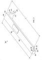
- the verification tool 200 includes a first portion 210 and a second portion 220 (i.e., elongated portion).
- the second portion 220 is adjoined to the first portion 210 and includes a maximum surface 222 and a minimum surface 224.
- the maximum and minimum surfaces 222, 224 may be used to determine whether an inboard surface 310 (i.e., yoke-measuring surface) of the yoke 300 (e.g., as shown in FIGS.
- the maximum surface 222 may correspond to a maximum suitable distance (L1) (i.e., maximum interval, maximum length extension) between the mating surface 410 of the cross-head 400 (e.g., as shown in FIGS. 3-4 ) and the inboard surface 310 of the yoke 300.
- L1 maximum suitable distance
- the minimum surface 224 may correspond to a minimum suitable distance between (L2) (i.e., minimum interval, minimum length extension) between the mating surface 410 of the cross-head 400 and the inboard surface 310 of the yoke 300.
- the verification tool 200 may be made of any stable material that is machinable within a given tolerance (e.g., a composite steel material).
- the first portion 210 is adjoined to the second portion 220 on a first end 242 of the second portion 220, and the maximum and minimum surfaces 222, 224 are arranged on a second end 244 of the second portion 220. Moreover, the first and second ends 242, 244 may be on opposing ends of the second portion 220 of the verification tool 200.
- a positioning surface 213 located on the first portion 210 as well as the inboard surface 310 of the yoke 300 may be substantially parallel to the maximum and minimum surfaces 222, 224 of the second portion 220.
- the term "parallel”, as applied to portions and/or surfaces, shall be defined as portions and/or surfaces progressing so that the interval between them remains the same, within an applicable manufacturing tolerance.
- the positioning surface 213 and/or the inboard surface 310 of the yoke 300 as being parallel to the maximum and minimum surfaces 222, 224 of the second portion 220 are included in respective geometric planes that are parallel in space within an applicable manufacturing tolerance.
- the first portion 210 of the verification tool 200 is configured to align a convex curvature 420 of the cross-head 400 (e.g., as shown in FIGS. 3-4 ).
- the first portion 210 includes a concave curvature 212 that is configured to align the convex curvature 420 of the cross-head 400 on a first end 232 of the first portion 210.
- the first portion 210 includes a positioning surface 213 that can be configured to contact a mating surface 410 of the cross-head 400. Also, in such cases and others, the first portion 210 may be adjoined to the second portion 220 on a second end 234 of the first portion 210.
- the maximum length extension (L1) of the second portion 220 is of a greater length than that of a minimum length extension (L2) of the second portion 220.
- the maximum and minimum length extensions (L1, L2) may define maximum and minimum intervals, respectively, between the cross-head 400 (e.g., as shown in FIGS. 3-4 ) and the inboard surface 310 of the yoke 300 (e.g., as shown in FIGS. 3-4 ).
- the maximum length extension (L1) corresponds to the maximum surface 222
- the minimum length extension (L2) corresponds to the minimum surface 224.
- the second portion 220 of the verification tool 200 may include an upper surface 226 and a lower surface 228.
- the upper surface 226 may be flat (i.e., level).
- the upper surface 226 of second portion 220 may be configured to align substantially perpendicular to the tail rotor yoke 300 and/or the tail rotor cross-head 400.
- the lower surface 228 may have a convex curvature.
- the lower surface 228 of the second portion 220 may be configured to align to a concave curvature 320 of the yoke 300.
- the first portion 210 of the verification tool 200 may be exactly or approximately perpendicular to the upper and lower surfaces 226, 228 of the second portion 220. Further, the maximum and minimum surfaces 222, 224 may also be exactly or approximately perpendicular to the upper and lower surfaces 226, 228 of the second portion 220.
- the maximum surface 222 may include an overlap 223 (i.e., an overlap feature, an overhang).
- the maximum surface 222 may be configured to overhang (i.e., partially cover) the inboard surface 310 of the tail rotor yoke 300, thus, facilitating efficient and accurate determinations of the inboard surface 320 positioning.
- the overlap 223 were to prevent the verification tool 200 from adequately resting on the tail rotor yoke 300 as a result of the overlap's 223 placement, adjustments of the actuator output tube 500 would be desired.
- the inbound surface 310 if the inbound surface 310 "falls" at a length less than the maximum length extension LI, then the inbound surface would fall to the inside of the maximum surface 222. Thus, the verification tool 200 would “sit down” (i.e., fit appropriately) in a tail rotor assembly.
- the yoke measuring surface if the yoke measuring surface "falls” at a length longer than the maximum length LI, then the inbound surface 310 would be beyond the maximum surface 222, and the overlap 223 would prevent the verification tool 200 from sitting properly in the tail rotor assembly. Accordingly, the precise positioning of the maximum and minimum surfaces 222, 224 allow for proper evaluation of the inboard surface 320 of the tail rotor yoke 300 relative to the cross-head 400.
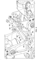
- FIGS. 3 and 4 perspective views of the positioning of devices (i.e., verification tools) 100, 200, respectively, relative to a tail rotor mast including the yoke 300, the cross-head 400, the control tube 500, and the gearbox 600 are shown.
- FIG. 3 illustrates an example positioning of the verification tool 100
- FIG. 4 illustrates an example positioning of the verification tool 200.
- FIG. 5 a perspective view of the control tube 500 passing through a tail rotor actuator 700 is shown.
- flight control inputs from a pilot may be converted to actuation inputs for an actuator 700 to cause selective actuation of an actuator yoke 710 and a control tube 500 (i.e., actuator output tube).
- actuation inputs for an actuator 700 to cause selective actuation of an actuator yoke 710 and a control tube 500 (i.e., actuator output tube).
- the actuator 700 causes linear translation of the control tube 500, such that the cross-head 400 (e.g., as shown in FIGS. 3-4 ) is either extended or retracted.
- the extension and/or retraction of the cross-head 400 may cause pitch links 450 (e.g., as shown in FIG. 3 ) to alter deflection angles of tail rotor blades (not shown).
- the control tube 500 may be coupled to the cross-head 400 at one end and coupled to the actuator yoke 710 of the actuator 700 on opposite sides of an empennage (not shown).
- the control tube 500 may pass through, thereby coupling: the cross-head 400, the tail rotor yoke 300, and the gearbox 600.
- the control tube 500 may thread through the actuator yoke 710 of the actuator 700 and align substantially parallel to the piston/cylinder assemblies 720 of the actuator 700.
- the positioning surface 113, 213 may be configured to align substantially perpendicular to the control tube 500.
- the second portion 120, 220 of the verification tool 100, 200 may be configured to align substantially parallel to the control tube 500.
- the verification device 100, 200 is positioned on the tail rotor yoke 300 and tail rotor cross-head 400.
- the concave curvature 112, 212 of the first end 110, 210 of the verification device 100, 200 may be positioned on the convex curvature 420 of the tail rotor cross-head 400.
- the positioning surface 113, 213 on the first portion 110, 210 may be positioned to contact a mating surface 410 of the cross-head 400.
- the convex curvature of the lower surface 128, 228 of the second portion 120, 220 may be positioned to the concave curvature 320 of the tail rotor yoke 300.
- an evaluation can be made whether the inboard surface 310 of the tail rotor yoke 300 is positioned between respective geometric planes of maximum and minimum surfaces 122, 222, 124, 224 of the verification tool 100, 200. If the inboard surface 310 lies within the max/min range 125, 225, then the tail rotor cross-head 400 may be correctly positioned.
- the tail rotor actuator output tube (i.e., control tube) 500 may be adjusted based on the determination of the positioned verification tool 100, 200.
- the following is an example verification and adjustment operation of tail rotor rigging of a rotorcraft.
- the verification device 100, 200, along with aircraft mating surfaces, including the cross-head 400 and the tail rotor yoke 300 are cleaned to remove grease, oil, dirt, and other particulates. Also, this operation assumes that sufficient hydraulic and electrical power is provided to the rotorcraft from maintenance equipment, and that the collective lever is positioned such that a level cross-head condition is commanded.
- the verification tool 100, 200 may be initially positioned on convex and concave curvatures 420, 320 of the cross-head 400 and the tail rotor yoke 300, respectively. After the initial positioning, an inboard surface 310 of the tail rotor yoke 300 may be evaluated to determine whether the inboard surface 310 lies between the respective geometric planes of maximum and minimum surfaces 122, 222, 124, 224 of the verification tool 100, 200.
- the tail rotor cross-head 400 may be correctly positioned. However, if the inboard surface 310 lies outside the max/min range 125, 225, then the tail rotor cross-head 400 may be deemed incorrectly positioned. Accordingly, in such cases, based on the determination of the positioned verification tool 100, 200, an adjustment of the control tube 500 would be desired.
- external hydraulic power Prior to adjusting the control tube 500, external hydraulic power may be turned off. Also, as shown in FIG. 5 , electrical harnesses 820 are removed from clamps 830, and subsequently, disconnected from the control tube 500. Next, a washer tab (not shown) may be bent such that a nut 810 may be loosened. The nut 810 is then loosened and adjusted away from the actuator yoke 710 such that a lock washer 840 disengages from locking slots (not shown) of the control tube 500.
- wrenching flats 510 may be rotated such that the inboard surface 310 of the tail rotor yoke 300 lies between the respective geometric planes of maximum and minimum surfaces 122, 222, 124, 224 of the verification tool 100, 200.
- one full turn (i.e., one revolution) of the control tube 500 may correspond to a 0.083-inch displacement of the cross-head 400.
- the lock washer 840 may be repositioned such that it engages the locking slots (not shown) and the nut 810 may be tightened.
- the electrical harnesses 820 may be reconnected and installed into the clamps 830. Upon confirmation of adequate harness slack between the clamps 830 and the control tube 500 to accommodate an entire range of actuator motion, the external hydraulic power may be turned back on.
- a second determination using the verification tool 100, 200 may again be performed on the cross-head 400 and the tail rotor yoke 300 to verify proper tail rotor rigging.
- FIG. 6 is a flowchart of a method of verifying tail rotor rigging of a rotorcraft positioning of a rotorcraft in accordance with implementations of various techniques described herein.
- Method 1000 is performed by a verification tool (e.g., a verification tools 100, 200 as described with reference to FIGS. 1 and 2 ), the yoke 300, the cross-head 400, the control tube 500, and the actuator 700 of FIGS. 1-5 .
- a verification tool e.g., a verification tools 100, 200 as described with reference to FIGS. 1 and 2
- the yoke 300 the cross-head 400, the control tube 500, and the actuator 700 of FIGS. 1-5 .
- method 1000 includes a first determination, using a verification tool, whether an inboard surface (i.e., a yoke-measuring surface) of a tail rotor yoke that is coupled to an actuator using a control tube is positioned between respective geometric planes of maximum and minimum surfaces of the verification tool.
- the verification tool 100, 200 is used to determine whether the inboard surface 310 lies between the respective geometric planes of maximum and minimum surfaces 122, 222, 124, 224 of the verification tool 100, 200.
- control tube is adjusted.
- the control tube 500 may be adjusted.
- wrench flats 510 may be rotated such that the inboard surface 310 of the tail rotor yoke 300 lies between the respective geometric planes of maximum and minimum surfaces 122, 222, 124, 224 of the verification tool 100, 200.
- the verification tool 100, 200 is used to confirm that the inboard surface 310 lies between the respective geometric planes of maximum and minimum surfaces 122, 222, 124, 224 of the verification tool 100, 200.
- Each of the processes of illustrative method 1000 may be performed or carried out by a system integrator, a third party, and/or an operator (e.g., a customer).
- a system integrator may include, without limitation, any number of manufacturers and major-system subcontractors
- a third party may include, without limitation, any number of vendors, subcontractors, and suppliers
- an operator may be a leasing company, military entity, service organization, and so on.
- first, second, etc. are used herein merely as labels, and are not intended to impose ordinal, positional, or hierarchical requirements on the items to which these terms refer. Moreover, reference to, e.g., a “second” item does not require or preclude the existence of, e.g., a "first” or lower-numbered item, and/or, e.g., a "third" or higher-numbered item.
- Device(s) and method(s) shown or described herein may be employed during any one or more of the stages of the verification of cross-head positioning and/or tail rotor rigging of the device 100, the device 200, and the method 1000.
Landscapes
- Engineering & Computer Science (AREA)
- Aviation & Aerospace Engineering (AREA)
- Transportation (AREA)
- Manufacturing & Machinery (AREA)
- Physics & Mathematics (AREA)
- General Physics & Mathematics (AREA)
- Mechanical Engineering (AREA)
- Manufacture Of Motors, Generators (AREA)
- Pressure Welding/Diffusion-Bonding (AREA)
- Connection Of Plates (AREA)
- Turbine Rotor Nozzle Sealing (AREA)
Claims (13)
- Vorrichtung (100, 200) zur Verifizierung der Positionierung des Heckrotorkreuzkopfs (400), umfassend:einen ersten Abschnitt (110, 210), der eine Positionierungsfläche (113, 213) und eine konkave Krümmung (112, 212) aufweist, die dazu ausgestaltet ist, wenn sie in Gebrauch ist, eine konvexe Krümmung (420) des Heckrotorkreuzkopfs (400) auf ein erstes Ende (132, 232) des ersten Abschnitts (110, 210) auszurichten,und einen zweiten Abschnitt (120, 220) mit einem ersten Ende (242), das mit dem ersten Abschnitt (110, 210) verbunden ist, wobei der zweite Abschnitt (120, 220) Folgendes umfasst:eine Maximalfläche (122, 222), die an einem zweiten Ende (144) des zweiten Abschnitts (120, 220) mit einem ersten Abstand (L1) von der Positionierungsfläche (113, 213) an dem ersten Abschnitt (110, 210) angeordnet ist, undeine Minimalfläche (124, 224), die an dem zweiten Ende (144) des zweiten Abschnitts (120, 220) mit einem zweiten Abstand (L2) von der Positionierungsfläche (113, 213) an dem ersten Abschnitt (110, 210) angeordnet ist,wobei der erste Abstand (L1) größer als der zweite Abstand (L2) ist undwobei sowohl die Maximalfläche (122, 222), die mit dem ersten Abstand (L1) von der Positionierungsfläche an dem ersten Abschnitt (110, 210) angeordnet ist, als auch die Minimalfläche (124, 224), die mit dem zweiten Abstand (L2) von der Positionierungsfläche an dem ersten Abschnitt (110, 210) angeordnet ist, parallel zu der Positionierungsfläche (113, 213) an dem ersten Abschnitt (110, 210) verlaufen.
- Vorrichtung (100, 200) nach Anspruch 1, wobei das erste Ende (242) und das zweite Ende (144) an gegenüberliegenden Enden des zweiten Abschnitts (120, 210) liegen.
- Vorrichtung (100, 200) nach Anspruch 1 oder 2, wobei die Positionierungsfläche (113, 213), die sich an dem ersten Abschnitt (110, 210) befindet, und die konkave Krümmung in der Nähe des ersten Endes (132) des ersten Abschnitts (110, 210) angeordnet sind.
- Vorrichtung (100, 200) nach einem der vorhergehenden Ansprüche, wobei der zweite Abschnitt (120, 220) jeweils eine maximale und eine minimale Länge zwischen dem Heckrotorkreuzkopf (400) und dem Heckrotorjoch (300) definiert.
- Vorrichtung (100, 200) nach Anspruch 4, wobei die Maximalfläche (122, 222), die mit dem ersten Abstand (L1) von der Positionierungsfläche an dem ersten Abschnitt (110, 210) angeordnet ist, die maximale Länge zwischen einer Gegenfläche (410) des Heckrotorkreuzkopfs (400) und einer Jochmessfläche (310) des Heckrotorjochs (300) definiert, und
wobei die Minimalfläche (124, 224), die mit dem zweiten Abstand (L2) von der Positionierungsfläche an dem ersten Abschnitt (110, 210) angeordnet ist, die minimale Länge zwischen einer Gegenfläche (410) des Heckrotorkreuzkopfs (400) und der Jochmessfläche (310) des Heckrotorjochs (300) definiert. - Vorrichtung (100, 200) nach einem der vorhergehenden Ansprüche, wobei eine obere Fläche (226) des zweiten Abschnitts (220) flach ist und wobei eine untere Fläche (228) des zweiten Abschnitts (220) eine konvexe Krümmung umfasst.
- Vorrichtung (100, 200) nach Anspruch 6,wobei der erste Abschnitt (110, 210) im Wesentlichen senkrecht zu der oberen und/oder der unteren Fläche (226, 228) des zweiten Abschnitts (220) verläuft und/oderwobei die Maximalfläche (122, 222), die mit dem ersten Abstand (L1) von der Positionierungsfläche an dem ersten Abschnitt (110, 210) angeordnet ist, an einem Überlappungsmerkmal angeordnet ist, undwobei das Überlappungsmerkmal die Maximalfläche (122, 222), die mit dem ersten Abstand (L1) von der Positionierungsfläche an dem ersten Abschnitt (110, 210) angeordnet ist, über die untere Fläche (228) des zweiten Abschnitts (220) hinaus verlängert.
- Vorrichtung (100, 200) nach Anspruch 6 oder 7, wobei die Maximalfläche (122, 222), die mit dem ersten Abstand (L1) von der Positionierungsfläche an dem ersten Abschnitt (110, 210) angeordnet ist, und die Minimalfläche (124, 224), die mit dem zweiten Abstand (L2) von der Positionierungsfläche an dem ersten Abschnitt (110, 210) angeordnet ist, senkrecht zu der oberen und/oder der unteren Fläche (226, 228) des zweiten Abschnitts (220) verlaufen und/oder
wobei die Maximalfläche (122, 222), die mit dem ersten Abstand (L1) von der Positionierungsfläche an dem ersten Abschnitt (110, 210) angeordnet ist, und die Minimalfläche (124, 224), die mit dem zweiten Abstand (L2) von der Positionierungsfläche an dem ersten Abschnitt (110, 210) angeordnet ist, zwischen der oberen und der unteren Fläche (226, 228) des zweiten Abschnitts (220) positioniert sind. - Vorrichtung (100, 200) nach einem der vorhergehenden Ansprüche, wobei die Maximalfläche (122, 222), die mit dem ersten Abstand (L1) von der Positionierungsfläche an dem ersten Abschnitt (110, 210) angeordnet ist, an einem Überhang (223) angeordnet ist und wobei die Maximalfläche (122, 222), die mit dem ersten Abstand (L1) von der Positionierungsfläche an dem ersten Abschnitt (110, 210) angeordnet ist, dazu ausgestaltet ist, über eine Jochmessfläche (310) des Heckrotorjochs (300) hängt.
- Verfahren zum Verifizieren der Heckrotoraufhängung eines Drehflüglers, wobei der Heckrotor einen Heckrotorkreuzkopf (400) und ein Heckrotorjoch (300) umfasst, umfassend:Positionieren der Vorrichtung (100, 200) nach Anspruch 1 an dem Heckrotorjoch (300) und dem Heckrotorkreuzkopf (100),Bestimmen, ob eine Jochmessfläche (310) des Heckrotorjochs (300), die unter Einsatz eines Steuerrohrs (500) an einen Aktuator (700) gekoppelt ist, zwischen jeweiligen geometrischen Ebenen der Maximalfläche (122, 222), die mit dem ersten Abstand (L1) von der Positionierungsfläche an dem ersten Abschnitt (110, 210) angeordnet ist, und der Minimalfläche (124, 224), die mit dem zweiten Abstand (L2) von der Fläche an dem ersten Abschnitt (110, 210) der Vorrichtung (100, 200) angeordnet ist, positioniert ist,Einstellen des Steuerrohrs (500) undBestimmen, ob die Jochmessfläche (310) des Heckrotorjochs (300) zwischen den jeweiligen geometrischen Ebenen der Maximalfläche (122, 222), die mit dem ersten Abstand (L1) von der Positionierungsfläche an dem ersten Abschnitt (110, 210) angeordnet ist, und der Minimalfläche (124, 224), die mit dem zweiten Abstand (L2) von der Positionierungsfläche an dem ersten Abschnitt (110, 210) der Vorrichtung (100, 200) angeordnet ist, positioniert ist.
- Verfahren nach Anspruch 10, wobei das Bestimmen der Positionierung der Fläche (310) ferner Folgendes umfasst:Positionieren einer konkaven Krümmung der Vorrichtung (100, 200) an einer konvexen Krümmung (420) eines Heckrotorkreuzkopfs (400),Positionieren einer Positionierungsfläche der Vorrichtung (100, 200) an einer Gegenfläche (410) des Heckrotorkreuzkopfs (400),Positionieren einer konvexen Krümmung der Vorrichtung (100, 200) an einer konkaven Krümmung (320) des Heckrotorjochs (300) undBeurteilen, ob die Fläche (310) des Heckrotorjochs (300) zwischen den jeweiligen geometrischen Ebenen der Maximalfläche (122, 222), die mit dem ersten Abstand (L1) von der Positionierungsfläche an dem ersten Abschnitt (110, 210) angeordnet ist, und der Minimalfläche (124, 224), die mit dem zweiten Abstand (L2) von der Positionierungsfläche an dem ersten Abschnitt (110, 210) der Vorrichtung (100, 200) angeordnet ist, positioniert ist.
- Verfahren nach Anspruch 10 oder 11, wobei das Einstellen des Steuerrohrs (500) durch Drehen von Schlüsselansatzflächen des Steuerrohrs (500) erfolgt.
- Verfahren nach Anspruch 12, wobei eine Umdrehung des Steuerrohrs einer Verschiebung eines an das Heckrotorjoch (300) gekoppelten Heckrotorkreuzkopfs (400) von 2,1 mm (0,083 Zoll) entspricht.
Applications Claiming Priority (2)
| Application Number | Priority Date | Filing Date | Title |
|---|---|---|---|
| US201862658205P | 2018-04-16 | 2018-04-16 | |
| US16/183,385 US11040785B2 (en) | 2018-04-16 | 2018-11-07 | Devices and methods to verify tail rotor cross-head positioning |
Publications (2)
| Publication Number | Publication Date |
|---|---|
| EP3556665A1 EP3556665A1 (de) | 2019-10-23 |
| EP3556665B1 true EP3556665B1 (de) | 2022-03-09 |
Family
ID=65010695
Family Applications (1)
| Application Number | Title | Priority Date | Filing Date |
|---|---|---|---|
| EP19151060.1A Active EP3556665B1 (de) | 2018-04-16 | 2019-01-09 | Systeme und verfahren zur überprüfung der heckrotorquerkopfpositionierung |
Country Status (2)
| Country | Link |
|---|---|
| US (1) | US11040785B2 (de) |
| EP (1) | EP3556665B1 (de) |
Families Citing this family (2)
| Publication number | Priority date | Publication date | Assignee | Title |
|---|---|---|---|---|
| CN115432203A (zh) * | 2021-06-01 | 2022-12-06 | 惠阳航空螺旋桨有限责任公司 | 一种螺旋桨桨叶空间尺寸测量支架及测量方法 |
| CN114955001B (zh) * | 2022-06-17 | 2024-05-31 | 重庆大学 | 直升机尾传动系统模拟实验系统 |
Family Cites Families (16)
| Publication number | Priority date | Publication date | Assignee | Title |
|---|---|---|---|---|
| US1558678A (en) * | 1925-03-16 | 1925-10-27 | Richard F Koenig | Paper-hanger's trimming gauge |
| US2229124A (en) * | 1939-11-04 | 1941-01-21 | Hastings Mfg Co | Piston groove depth gauge |
| US2536401A (en) * | 1944-09-14 | 1951-01-02 | Victor Victor | Gauge block |
| US3201873A (en) * | 1963-05-29 | 1965-08-24 | James C Bell | Gage block |
| US4065854A (en) * | 1976-09-29 | 1978-01-03 | Reed Donald M | Dimensional gauging apparatus |
| US4584774A (en) * | 1984-11-26 | 1986-04-29 | Link Glennie W | Step gauge for setting up wood working tools for specialty processing |
| FR2574924B1 (fr) * | 1984-12-13 | 1987-11-20 | Knoblauch Georg | Jauge de profondeur pour trous de cheville |
| US5042161A (en) * | 1985-10-07 | 1991-08-27 | Joseph Hodge | Intravascular sizing method and apparatus |
| JPH11510127A (ja) | 1995-07-27 | 1999-09-07 | アールトン,ポール・イー | 回転翼航空機の回転運動の制御及び自動安定用のシステム |
| US6434852B1 (en) * | 2000-02-09 | 2002-08-20 | Pacific Rack & Machine, Llc | Tool gauge |
| CA2775433C (en) * | 2011-04-20 | 2018-10-30 | Muncie Power Products, Inc. | Power takeoff gasket selection tools and methods |
| US8793856B2 (en) | 2012-02-20 | 2014-08-05 | Bell Helicopter Textron Inc. | Pitch link alignment tool |
| US8887407B2 (en) * | 2012-03-05 | 2014-11-18 | Maricela Carlota Silva | Propeller blade seal positioning gauge |
| US9151162B2 (en) * | 2012-11-08 | 2015-10-06 | Bell Helicopter Textron Inc. | Preventing rotation of a fixed ring of a swashplate |
| US10023304B2 (en) | 2014-05-23 | 2018-07-17 | Bell Helicopter Textron Inc. | Tail rotor actuation system |
| US20180319009A1 (en) * | 2016-01-15 | 2018-11-08 | Jamieson Byrt | Pipe spacing wedge systems |
-
2018
- 2018-11-07 US US16/183,385 patent/US11040785B2/en active Active
-
2019
- 2019-01-09 EP EP19151060.1A patent/EP3556665B1/de active Active
Also Published As
| Publication number | Publication date |
|---|---|
| US20190315495A1 (en) | 2019-10-17 |
| EP3556665A1 (de) | 2019-10-23 |
| US11040785B2 (en) | 2021-06-22 |
Similar Documents
| Publication | Publication Date | Title |
|---|---|---|
| JP6971080B2 (ja) | 翼及び製造方法 | |
| US11242129B2 (en) | Aerofoil structure and method of assembly | |
| EP3260708A1 (de) | Flüssigkeitsdichtes mechanisches befestigungssystem und zugehörige strukturanordnung | |
| US8033500B1 (en) | Actuator load path monitoring system | |
| EP3196509A2 (de) | Linearaktuatorsystem mit in umfangs- und achsrichtung verstellbarerer endanschlaganordnung | |
| US20140033729A1 (en) | Method for mounting an aircraft engine on a pylon, and engine fastener for implementing said method | |
| EP0485027A2 (de) | Herstellung eines Tragflügels aus Kohlenfaserverbundwerkstoff | |
| EP3770407B1 (de) | Aufhängungdichtung eines gasturbinenmotors | |
| US11040785B2 (en) | Devices and methods to verify tail rotor cross-head positioning | |
| US10604246B2 (en) | Rotorcraft rotor assemblies | |
| EP2876045B1 (de) | Verbindungsanordnung und Verfahren zur Verbindung derselben. | |
| US9475576B2 (en) | Flexbeam rotor attachment to rotor blade | |
| US20190367174A1 (en) | Aircraft propulsive assembly and method for checking the integrity of an engine attachment of the propulsive assembly | |
| US11679861B2 (en) | Assembly for an aircraft, the assembly having a pylon and a wing | |
| US11407519B2 (en) | Rear engine attachment for an aircraft propulsion unit | |
| US10569906B2 (en) | Apparatus and methods for making rotorcraft rotor blades | |
| WO2010138251A1 (en) | Elliptical locating apparatus | |
| US20170081015A1 (en) | Wing structure, stringer structure, and related apparatus and methods of assembly | |
| CN105197247B (zh) | 一种夹持式航空发动机主安装节机构 | |
| EP1845873B1 (de) | Messgerät und messverfahren für eine rotorblatthalterung | |
| US20100299903A1 (en) | Angled Locating Apparatus | |
| EP3770069A1 (de) | System und verfahren zur montage eines gasturbinenmotors mit dichtung | |
| EP3741686B1 (de) | Montage- und installationsverfahren einer unterflügelanordnung und transfersystem dazu | |
| EP3867143B1 (de) | Verfahren zur herstellung einer aerodynamischen struktur | |
| US20180312249A1 (en) | Rotor blade snubber retainer for a rotary wing aircraft |
Legal Events
| Date | Code | Title | Description |
|---|---|---|---|
| STAA | Information on the status of an ep patent application or granted ep patent |
Free format text: STATUS: EXAMINATION IS IN PROGRESS |
|
| PUAI | Public reference made under article 153(3) epc to a published international application that has entered the european phase |
Free format text: ORIGINAL CODE: 0009012 |
|
| 17P | Request for examination filed |
Effective date: 20190109 |
|
| AK | Designated contracting states |
Kind code of ref document: A1 Designated state(s): AL AT BE BG CH CY CZ DE DK EE ES FI FR GB GR HR HU IE IS IT LI LT LU LV MC MK MT NL NO PL PT RO RS SE SI SK SM TR |
|
| AX | Request for extension of the european patent |
Extension state: BA ME |
|
| GRAP | Despatch of communication of intention to grant a patent |
Free format text: ORIGINAL CODE: EPIDOSNIGR1 |
|
| STAA | Information on the status of an ep patent application or granted ep patent |
Free format text: STATUS: GRANT OF PATENT IS INTENDED |
|
| RIC1 | Information provided on ipc code assigned before grant |
Ipc: B64C 27/82 20060101ALN20210908BHEP Ipc: B64F 5/60 20170101ALI20210908BHEP Ipc: G01B 5/25 20060101ALI20210908BHEP Ipc: B64F 5/50 20170101AFI20210908BHEP |
|
| RIC1 | Information provided on ipc code assigned before grant |
Ipc: B64C 27/82 20060101ALN20210913BHEP Ipc: B64F 5/60 20170101ALI20210913BHEP Ipc: G01B 5/25 20060101ALI20210913BHEP Ipc: B64F 5/50 20170101AFI20210913BHEP |
|
| INTG | Intention to grant announced |
Effective date: 20211007 |
|
| GRAS | Grant fee paid |
Free format text: ORIGINAL CODE: EPIDOSNIGR3 |
|
| GRAA | (expected) grant |
Free format text: ORIGINAL CODE: 0009210 |
|
| STAA | Information on the status of an ep patent application or granted ep patent |
Free format text: STATUS: THE PATENT HAS BEEN GRANTED |
|
| AK | Designated contracting states |
Kind code of ref document: B1 Designated state(s): AL AT BE BG CH CY CZ DE DK EE ES FI FR GB GR HR HU IE IS IT LI LT LU LV MC MK MT NL NO PL PT RO RS SE SI SK SM TR |
|
| REG | Reference to a national code |
Ref country code: CH Ref legal event code: EP Ref country code: AT Ref legal event code: REF Ref document number: 1473968 Country of ref document: AT Kind code of ref document: T Effective date: 20220315 |
|
| REG | Reference to a national code |
Ref country code: DE Ref legal event code: R096 Ref document number: 602019012240 Country of ref document: DE |
|
| REG | Reference to a national code |
Ref country code: IE Ref legal event code: FG4D |
|
| RAP2 | Party data changed (patent owner data changed or rights of a patent transferred) |
Owner name: TEXTRON INNOVATIONS INC. |
|
| REG | Reference to a national code |
Ref country code: DE Ref legal event code: R081 Ref document number: 602019012240 Country of ref document: DE Owner name: TEXTRON INNOVATIONS INC., PROVIDENCE, US Free format text: FORMER OWNER: BELL HELICOPTER TEXTRON INC., FORT WORTH, TX, US |
|
| REG | Reference to a national code |
Ref country code: LT Ref legal event code: MG9D |
|
| REG | Reference to a national code |
Ref country code: NL Ref legal event code: MP Effective date: 20220309 Ref country code: GB Ref legal event code: 732E Free format text: REGISTERED BETWEEN 20220616 AND 20220622 |
|
| PG25 | Lapsed in a contracting state [announced via postgrant information from national office to epo] |
Ref country code: SE Free format text: LAPSE BECAUSE OF FAILURE TO SUBMIT A TRANSLATION OF THE DESCRIPTION OR TO PAY THE FEE WITHIN THE PRESCRIBED TIME-LIMIT Effective date: 20220309 Ref country code: RS Free format text: LAPSE BECAUSE OF FAILURE TO SUBMIT A TRANSLATION OF THE DESCRIPTION OR TO PAY THE FEE WITHIN THE PRESCRIBED TIME-LIMIT Effective date: 20220309 Ref country code: NO Free format text: LAPSE BECAUSE OF FAILURE TO SUBMIT A TRANSLATION OF THE DESCRIPTION OR TO PAY THE FEE WITHIN THE PRESCRIBED TIME-LIMIT Effective date: 20220609 Ref country code: LT Free format text: LAPSE BECAUSE OF FAILURE TO SUBMIT A TRANSLATION OF THE DESCRIPTION OR TO PAY THE FEE WITHIN THE PRESCRIBED TIME-LIMIT Effective date: 20220309 Ref country code: HR Free format text: LAPSE BECAUSE OF FAILURE TO SUBMIT A TRANSLATION OF THE DESCRIPTION OR TO PAY THE FEE WITHIN THE PRESCRIBED TIME-LIMIT Effective date: 20220309 Ref country code: BG Free format text: LAPSE BECAUSE OF FAILURE TO SUBMIT A TRANSLATION OF THE DESCRIPTION OR TO PAY THE FEE WITHIN THE PRESCRIBED TIME-LIMIT Effective date: 20220609 |
|
| REG | Reference to a national code |
Ref country code: AT Ref legal event code: MK05 Ref document number: 1473968 Country of ref document: AT Kind code of ref document: T Effective date: 20220309 |
|
| PG25 | Lapsed in a contracting state [announced via postgrant information from national office to epo] |
Ref country code: LV Free format text: LAPSE BECAUSE OF FAILURE TO SUBMIT A TRANSLATION OF THE DESCRIPTION OR TO PAY THE FEE WITHIN THE PRESCRIBED TIME-LIMIT Effective date: 20220309 Ref country code: GR Free format text: LAPSE BECAUSE OF FAILURE TO SUBMIT A TRANSLATION OF THE DESCRIPTION OR TO PAY THE FEE WITHIN THE PRESCRIBED TIME-LIMIT Effective date: 20220610 Ref country code: FI Free format text: LAPSE BECAUSE OF FAILURE TO SUBMIT A TRANSLATION OF THE DESCRIPTION OR TO PAY THE FEE WITHIN THE PRESCRIBED TIME-LIMIT Effective date: 20220309 |
|
| PG25 | Lapsed in a contracting state [announced via postgrant information from national office to epo] |
Ref country code: NL Free format text: LAPSE BECAUSE OF FAILURE TO SUBMIT A TRANSLATION OF THE DESCRIPTION OR TO PAY THE FEE WITHIN THE PRESCRIBED TIME-LIMIT Effective date: 20220309 |
|
| PG25 | Lapsed in a contracting state [announced via postgrant information from national office to epo] |
Ref country code: SM Free format text: LAPSE BECAUSE OF FAILURE TO SUBMIT A TRANSLATION OF THE DESCRIPTION OR TO PAY THE FEE WITHIN THE PRESCRIBED TIME-LIMIT Effective date: 20220309 Ref country code: SK Free format text: LAPSE BECAUSE OF FAILURE TO SUBMIT A TRANSLATION OF THE DESCRIPTION OR TO PAY THE FEE WITHIN THE PRESCRIBED TIME-LIMIT Effective date: 20220309 Ref country code: RO Free format text: LAPSE BECAUSE OF FAILURE TO SUBMIT A TRANSLATION OF THE DESCRIPTION OR TO PAY THE FEE WITHIN THE PRESCRIBED TIME-LIMIT Effective date: 20220309 Ref country code: PT Free format text: LAPSE BECAUSE OF FAILURE TO SUBMIT A TRANSLATION OF THE DESCRIPTION OR TO PAY THE FEE WITHIN THE PRESCRIBED TIME-LIMIT Effective date: 20220711 Ref country code: ES Free format text: LAPSE BECAUSE OF FAILURE TO SUBMIT A TRANSLATION OF THE DESCRIPTION OR TO PAY THE FEE WITHIN THE PRESCRIBED TIME-LIMIT Effective date: 20220309 Ref country code: EE Free format text: LAPSE BECAUSE OF FAILURE TO SUBMIT A TRANSLATION OF THE DESCRIPTION OR TO PAY THE FEE WITHIN THE PRESCRIBED TIME-LIMIT Effective date: 20220309 Ref country code: CZ Free format text: LAPSE BECAUSE OF FAILURE TO SUBMIT A TRANSLATION OF THE DESCRIPTION OR TO PAY THE FEE WITHIN THE PRESCRIBED TIME-LIMIT Effective date: 20220309 Ref country code: AT Free format text: LAPSE BECAUSE OF FAILURE TO SUBMIT A TRANSLATION OF THE DESCRIPTION OR TO PAY THE FEE WITHIN THE PRESCRIBED TIME-LIMIT Effective date: 20220309 |
|
| PG25 | Lapsed in a contracting state [announced via postgrant information from national office to epo] |
Ref country code: PL Free format text: LAPSE BECAUSE OF FAILURE TO SUBMIT A TRANSLATION OF THE DESCRIPTION OR TO PAY THE FEE WITHIN THE PRESCRIBED TIME-LIMIT Effective date: 20220309 Ref country code: IS Free format text: LAPSE BECAUSE OF FAILURE TO SUBMIT A TRANSLATION OF THE DESCRIPTION OR TO PAY THE FEE WITHIN THE PRESCRIBED TIME-LIMIT Effective date: 20220709 Ref country code: AL Free format text: LAPSE BECAUSE OF FAILURE TO SUBMIT A TRANSLATION OF THE DESCRIPTION OR TO PAY THE FEE WITHIN THE PRESCRIBED TIME-LIMIT Effective date: 20220309 |
|
| REG | Reference to a national code |
Ref country code: DE Ref legal event code: R097 Ref document number: 602019012240 Country of ref document: DE |
|
| PLBE | No opposition filed within time limit |
Free format text: ORIGINAL CODE: 0009261 |
|
| STAA | Information on the status of an ep patent application or granted ep patent |
Free format text: STATUS: NO OPPOSITION FILED WITHIN TIME LIMIT |
|
| PG25 | Lapsed in a contracting state [announced via postgrant information from national office to epo] |
Ref country code: DK Free format text: LAPSE BECAUSE OF FAILURE TO SUBMIT A TRANSLATION OF THE DESCRIPTION OR TO PAY THE FEE WITHIN THE PRESCRIBED TIME-LIMIT Effective date: 20220309 |
|
| 26N | No opposition filed |
Effective date: 20221212 |
|
| PG25 | Lapsed in a contracting state [announced via postgrant information from national office to epo] |
Ref country code: SI Free format text: LAPSE BECAUSE OF FAILURE TO SUBMIT A TRANSLATION OF THE DESCRIPTION OR TO PAY THE FEE WITHIN THE PRESCRIBED TIME-LIMIT Effective date: 20220309 |
|
| P01 | Opt-out of the competence of the unified patent court (upc) registered |
Effective date: 20230602 |
|
| REG | Reference to a national code |
Ref country code: CH Ref legal event code: PL |
|
| PG25 | Lapsed in a contracting state [announced via postgrant information from national office to epo] |
Ref country code: LU Free format text: LAPSE BECAUSE OF NON-PAYMENT OF DUE FEES Effective date: 20230109 |
|
| REG | Reference to a national code |
Ref country code: BE Ref legal event code: MM Effective date: 20230131 |
|
| PG25 | Lapsed in a contracting state [announced via postgrant information from national office to epo] |
Ref country code: LI Free format text: LAPSE BECAUSE OF NON-PAYMENT OF DUE FEES Effective date: 20230131 Ref country code: CH Free format text: LAPSE BECAUSE OF NON-PAYMENT OF DUE FEES Effective date: 20230131 |
|
| PG25 | Lapsed in a contracting state [announced via postgrant information from national office to epo] |
Ref country code: BE Free format text: LAPSE BECAUSE OF NON-PAYMENT OF DUE FEES Effective date: 20230131 |
|
| PG25 | Lapsed in a contracting state [announced via postgrant information from national office to epo] |
Ref country code: IE Free format text: LAPSE BECAUSE OF NON-PAYMENT OF DUE FEES Effective date: 20230109 |
|
| PG25 | Lapsed in a contracting state [announced via postgrant information from national office to epo] |
Ref country code: MC Free format text: LAPSE BECAUSE OF FAILURE TO SUBMIT A TRANSLATION OF THE DESCRIPTION OR TO PAY THE FEE WITHIN THE PRESCRIBED TIME-LIMIT Effective date: 20220309 |
|
| PG25 | Lapsed in a contracting state [announced via postgrant information from national office to epo] |
Ref country code: MC Free format text: LAPSE BECAUSE OF FAILURE TO SUBMIT A TRANSLATION OF THE DESCRIPTION OR TO PAY THE FEE WITHIN THE PRESCRIBED TIME-LIMIT Effective date: 20220309 |
|
| PG25 | Lapsed in a contracting state [announced via postgrant information from national office to epo] |
Ref country code: CY Free format text: LAPSE BECAUSE OF FAILURE TO SUBMIT A TRANSLATION OF THE DESCRIPTION OR TO PAY THE FEE WITHIN THE PRESCRIBED TIME-LIMIT; INVALID AB INITIO Effective date: 20190109 |
|
| PG25 | Lapsed in a contracting state [announced via postgrant information from national office to epo] |
Ref country code: HU Free format text: LAPSE BECAUSE OF FAILURE TO SUBMIT A TRANSLATION OF THE DESCRIPTION OR TO PAY THE FEE WITHIN THE PRESCRIBED TIME-LIMIT; INVALID AB INITIO Effective date: 20190109 |
|
| PG25 | Lapsed in a contracting state [announced via postgrant information from national office to epo] |
Ref country code: TR Free format text: LAPSE BECAUSE OF FAILURE TO SUBMIT A TRANSLATION OF THE DESCRIPTION OR TO PAY THE FEE WITHIN THE PRESCRIBED TIME-LIMIT Effective date: 20220309 |
|
| PGFP | Annual fee paid to national office [announced via postgrant information from national office to epo] |
Ref country code: GB Payment date: 20260127 Year of fee payment: 8 |
|
| PGFP | Annual fee paid to national office [announced via postgrant information from national office to epo] |
Ref country code: DE Payment date: 20260128 Year of fee payment: 8 |
|
| PGFP | Annual fee paid to national office [announced via postgrant information from national office to epo] |
Ref country code: IT Payment date: 20260121 Year of fee payment: 8 |
|
| PGFP | Annual fee paid to national office [announced via postgrant information from national office to epo] |
Ref country code: FR Payment date: 20260126 Year of fee payment: 8 |