EP3556654B1 - Payload engagement systems, vehicles including the same, and related methods - Google Patents
Payload engagement systems, vehicles including the same, and related methods Download PDFInfo
- Publication number
- EP3556654B1 EP3556654B1 EP19165955.6A EP19165955A EP3556654B1 EP 3556654 B1 EP3556654 B1 EP 3556654B1 EP 19165955 A EP19165955 A EP 19165955A EP 3556654 B1 EP3556654 B1 EP 3556654B1
- Authority
- EP
- European Patent Office
- Prior art keywords
- payload
- securement
- engagement system
- receptor
- vehicle
- Prior art date
- Legal status (The legal status is an assumption and is not a legal conclusion. Google has not performed a legal analysis and makes no representation as to the accuracy of the status listed.)
- Active
Links
Images


Classifications
-
- B—PERFORMING OPERATIONS; TRANSPORTING
- B64—AIRCRAFT; AVIATION; COSMONAUTICS
- B64D—EQUIPMENT FOR FITTING IN OR TO AIRCRAFT; FLIGHT SUITS; PARACHUTES; ARRANGEMENT OR MOUNTING OF POWER PLANTS OR PROPULSION TRANSMISSIONS IN AIRCRAFT
- B64D1/00—Dropping, ejecting, releasing or receiving articles, liquids, or the like, in flight
- B64D1/02—Dropping, ejecting, or releasing articles
- B64D1/08—Dropping, ejecting, or releasing articles the articles being load-carrying devices
- B64D1/12—Releasing
-
- B—PERFORMING OPERATIONS; TRANSPORTING
- B64—AIRCRAFT; AVIATION; COSMONAUTICS
- B64D—EQUIPMENT FOR FITTING IN OR TO AIRCRAFT; FLIGHT SUITS; PARACHUTES; ARRANGEMENT OR MOUNTING OF POWER PLANTS OR PROPULSION TRANSMISSIONS IN AIRCRAFT
- B64D9/00—Equipment for handling freight; Equipment for facilitating passenger embarkation or the like
-
- B—PERFORMING OPERATIONS; TRANSPORTING
- B64—AIRCRAFT; AVIATION; COSMONAUTICS
- B64D—EQUIPMENT FOR FITTING IN OR TO AIRCRAFT; FLIGHT SUITS; PARACHUTES; ARRANGEMENT OR MOUNTING OF POWER PLANTS OR PROPULSION TRANSMISSIONS IN AIRCRAFT
- B64D1/00—Dropping, ejecting, releasing or receiving articles, liquids, or the like, in flight
- B64D1/22—Taking-up articles from earth's surface
-
- B—PERFORMING OPERATIONS; TRANSPORTING
- B64—AIRCRAFT; AVIATION; COSMONAUTICS
- B64U—UNMANNED AERIAL VEHICLES [UAV]; EQUIPMENT THEREFOR
- B64U10/00—Type of UAV
- B64U10/10—Rotorcrafts
- B64U10/13—Flying platforms
-
- B—PERFORMING OPERATIONS; TRANSPORTING
- B64—AIRCRAFT; AVIATION; COSMONAUTICS
- B64U—UNMANNED AERIAL VEHICLES [UAV]; EQUIPMENT THEREFOR
- B64U2101/00—UAVs specially adapted for particular uses or applications
- B64U2101/60—UAVs specially adapted for particular uses or applications for transporting passengers; for transporting goods other than weapons
- B64U2101/64—UAVs specially adapted for particular uses or applications for transporting passengers; for transporting goods other than weapons for parcel delivery or retrieval
-
- B—PERFORMING OPERATIONS; TRANSPORTING
- B64—AIRCRAFT; AVIATION; COSMONAUTICS
- B64U—UNMANNED AERIAL VEHICLES [UAV]; EQUIPMENT THEREFOR
- B64U2201/00—UAVs characterised by their flight controls
- B64U2201/10—UAVs characterised by their flight controls autonomous, i.e. by navigating independently from ground or air stations, e.g. by using inertial navigation systems [INS]
-
- B—PERFORMING OPERATIONS; TRANSPORTING
- B64—AIRCRAFT; AVIATION; COSMONAUTICS
- B64U—UNMANNED AERIAL VEHICLES [UAV]; EQUIPMENT THEREFOR
- B64U2201/00—UAVs characterised by their flight controls
- B64U2201/20—Remote controls
-
- F—MECHANICAL ENGINEERING; LIGHTING; HEATING; WEAPONS; BLASTING
- F16—ENGINEERING ELEMENTS AND UNITS; GENERAL MEASURES FOR PRODUCING AND MAINTAINING EFFECTIVE FUNCTIONING OF MACHINES OR INSTALLATIONS; THERMAL INSULATION IN GENERAL
- F16B—DEVICES FOR FASTENING OR SECURING CONSTRUCTIONAL ELEMENTS OR MACHINE PARTS TOGETHER, e.g. NAILS, BOLTS, CIRCLIPS, CLAMPS, CLIPS OR WEDGES; JOINTS OR JOINTING
- F16B21/00—Means for preventing relative axial movement of a pin, spigot, shaft or the like and a member surrounding it; Stud-and-socket releasable fastenings
- F16B21/02—Releasable fastening devices locking by rotation
- F16B21/04—Releasable fastening devices locking by rotation with bayonet catch
Definitions
- the present disclosure relates to payload engagement systems, vehicles including the same, and related methods.
- Vehicles such as aircraft may be used to deliver payloads to a delivery site.
- UAVs unmanned aerial vehicles
- UAVs unmanned aerial vehicles
- Such human interaction with a UAV may necessitate the use of special procedures and/or apparatuses to ensure the safety of the human user, especially when the UAV is intended to interact with an untrained human user such as the end recipient of a delivered package.
- human interaction with a UAV may require the UAV to land and/or power off to couple the package to the UAV and/or to uncouple the package from the UAV, resulting in downtime between delivery runs.
- Disclosed is a package delivery mechanism (PDM) of an unmanned aerial vehicle (UAV).
- the PDM includes a gravity activated locking mechanism to lock and unlock a package attached to the UAV based on the weight of the package.
- the locking mechanism automatically engages with the package and keeps the package locked to the suspension means, due to the weight of the package.
- the weight of the package is offloaded from the suspension means, which enables the locking mechanism to be disengaged, thereby releasing the package.
- the PDM includes a severing module to sever the suspension means from the UAV.”
- the stem configured to be inserted through a key aperture in an accessory to be attached to the vehicle.
- the system includes a locking bracket connectable to the vehicle adjacent an accessory portal provided in the vehicle.
- the locking bracket comprises a base plate, a keyhole disposed through the base plate, and at least one inclined securing structure disposed along a circumference of the keyhole.
- Each securing structure comprises a ramp and a detent.
- the keyhole is configured to receive the stem distal end and bit(s) therethrough, and each securing structure is configured to engage the bit(s) and interlock the fastening key with the locking bracket upon rotation of the key.”
- the latching apparatus includes a cylinder attached to the first object and including a first opening, and a second opening laterally disposed to the first opening, a spring loaded piston including a circumferential wall disposed in the first opening, a shank axially extending from the piston and defining a transverse latch pin at an end thereof, and a spring loaded plunger disposed within the second opening.
- the wall defines a contiguous cam-groove thereon.
- the cam-groove includes alternating upper and lower nodal points with straight and inclined segments therebetween.
- the plunger slidably engages the cam-groove to co-operatively execute one or more of a translation, and a rotation of the shank such that the latch pin rotatably extends or retracts into or out of the slotted opening on the locking plate of the second object.”
- a locking device consists of a fastening member A and a receiving member B. Owing to the resilient force of a resilient member provided in the receiving member B, the fastening member A can be held reliably on the receiving member B, and the removing of the locking member A from the receiving member B can also be done easily.
- An end portion of the fastening member A is formed in the shape of the letter "T", in which a rod (2) extending perpendicularly to left and right with respect to a support post (1) is fixed to an end of the support post (1).
- a vertically acting resilient member (4) is provided in the interior of a chamber (3) in the receiving member B, and an elongated bore (6) in the portion of an upper wall (5) of the chamber (3) which is above the resilient member (4), a groove (7) being provided in the lower surface of the upper wall (5) of the chamber (3) so as to extend across the elongated bore (6).
- the elongated bore (6) and groove (7) in the receiving member B are all formed in such shapes that permit the rod (2) in the fastening member A to be held therein.
- the rod in the fastening member when the rod in the fastening member is inserted into the elongated bore in the receiving member B and turned in the interior of the chamber in the receiving member B up to the position of the groove, the rod of the fastening member A fits in the groove in the receiving member B for secure locking owing to the resilient force of the resilient member.
- the fastening member A is provided on either a decorative member (10) of a personal ornament, such as a brooch, a necklace, an earring and a button, or a mounting member (11) for a decorative element with the receiving member B provided on the other, a personal ornament having an interchangeable decorative member (10) can be provided.”
- the invention relates to a fastening device (8) for a vehicle (10), in particular an aircraft, with at least one first fastening module (12), which is provided for connection to a structural component (14) of the vehicle (10), and with at least one second fastening module (16) which is provided for attachment of at least one interior trim (18) of the vehicle (10). It is proposed that the fastening device (8) comprises at least one connecting unit (20) which is provided to connect the first fastening module (12) and the second fastening module (16) in an assembled state.”
- the device has an inserting part (2) insertable into a base for coupling construction units, where the inserting part is rotatable around a rotation axis (3).
- the inserting part exhibits two contact units (4) that interact with a locking mechanism (5) which is attached to the base.
- the locking mechanism has a movable pin for contacting with the contact units, where the pin is pre-stressed in a direction of the rotation axis.”
- Figs. 1-12 provide illustrative, non-exclusive examples of payload engagement systems 100, of vehicle 10 including portions of payload engagement systems 100, and/or of methods 200 of transporting a payload with a vehicle, according to the present disclosure.
- Elements that serve a similar, or at least substantially similar, purpose are labeled with like numbers in each of Figs. 1-12 , and these elements may not be discussed in detail herein with reference to each of Figs. 1-12 .
- all elements may not be labeled in each of Figs. 1-12 , but reference numerals associated therewith may be utilized herein for consistency.
- Elements, components, and/or features that are discussed herein with reference to one or more of Figs. 1-12 may be included in and/or utilized with any of Figs. 1-12 without departing from the scope of the present claimed invention, which is only defined by the appended claims.
- Figs. 1-2 are schematic illustrations of examples of payload engagement systems 100 and of payloads 50 according to the present disclosure.
- Fig. 1 additionally schematically illustrates an example of a vehicle 10 configured to support at least a portion of payload engagement system 100 and to carry payload 50 via payload engagement system 100.
- a payload engagement system 100 for selectively coupling a payload 50 to a vehicle 10 includes a vehicle supported portion 102 configured to be supported by vehicle 10 and a payload mounted portion 104 configured to be mounted on payload 50.
- Payload engagement system 100 may be configured to be utilized in conjunction with any appropriate vehicle 10.
- vehicle 10 may include and/or be an aircraft 11.
- vehicle 10 may include and/or be any appropriate vehicle for carrying a payload, such as a land-based vehicle, a water vehicle, a submersible water vehicle, and/or a space vehicle.
- aircraft 11 may include and/or be any appropriate aircraft.
- aircraft 11 may include and/or be a rotorcraft, such as a rotorcraft that includes two rotors, three rotors, four rotors, or more than four rotors.
- aircraft 11 may include and/or be an unmanned aerial vehicle (UAV) and/or a drone.
- UAV unmanned aerial vehicle
- aircraft 11 may be a remotely piloted UAV or may be an autonomously controlled UAV.
- Utilizing payload engagement system 100 in conjunction with aircraft 11 in the form of a UAV may facilitate transporting payload 50, such as a package, with little or no human intervention needed to couple payload 50 to aircraft 11 or to uncouple payload 50 from aircraft 11.
- utilizing payload engagement system 100 in conjunction with aircraft 11 may facilitate coupling payload 50 to aircraft 11 or uncoupling payload 50 from aircraft 11 while aircraft 11 remains in flight, thereby increasing a delivery turnaround speed relative to a system in which aircraft 11 needs to land and/or power off between delivery runs.
- Vehicle 10 may have any appropriate structure for supporting payload engagement system 100 and/or payload 50.
- vehicle 10 may include a vehicle body 12 and further may include a support structure 20 that extends from vehicle body 12 to support vehicle supported portion 102.
- support structure 20 may include a gimbal 22 configured to enable vehicle supported portion 102 to pivot with respect to vehicle body 12. Such a configuration may facilitate maintaining payload 50 in an upright orientation while vehicle 10 transports payload 50 independent of an orientation of vehicle 10.
- Payload engagement system 100 is configured to transition between a disengaged configuration and an engaged configuration at least partially via rotation of insert component 110 with respect to receptor component 150.
- Fig. 2 schematically illustrates payload engagement system 100 in the disengaged configuration in dash-dot lines and schematically illustrates payload engagement system 100 in the engaged configuration in solid and dashed lines.
- Payload engagement system 100 may be configured such that insert component 110 rotates with respect to receptor component 150 about any appropriate axis.
- insert component 110 may have an insert component central axis 112, and insert component 110 may be configured to rotate with respect to receptor component 150 about insert component central axis 112 when payload engagement system 100 transitions between the disengaged configuration and the engaged configuration.
- receptor component 150 may have a receptor component central axis 152
- insert component 110 may be configured to rotate with respect to receptor component 150 about receptor component central axis 152 when payload engagement system 100 transitions between the disengaged configuration and the engaged configuration.
- insert component 110 may be configured to rotate with respect to receptor component 150 about a vertical axis 106 when payload engagement system 100 transitions between the disengaged configuration and the engaged configuration.
- receptor component 150 receives and engages insert component 110 such that insert component 110 is rotationally constrained within receptor component 150 and such that a weight of payload 50 is supported by vehicle supported portion 102.
- receptor component 150 engages insert component 110 such that vehicle 10 is enabled to lift payload mounted portion 104, and hence payload 50, via vehicle supported portion 102. In this manner, the engagement between insert component 110 and receptor component 150 enables vehicle 10 to carry payload 50 when payload engagement system 100 is in the engaged configuration.
- payload engagement system 100 may be configured to support a payload weight that is at least 10 Newtons (N), at least 30 N, at least 50 N, at least 100 N, at least 300 N, at least 500 N, at most 1000 N, at most 700 N, at most 200 N, at most 70 N, and/or at most 20 N while the vehicle carries payload 50.
- N 10 Newtons
- payload engagement system 100 may be configured to support a payload weight that is at least 10 Newtons (N), at least 30 N, at least 50 N, at least 100 N, at least 300 N, at least 500 N, at most 1000 N, at most 700 N, at most 200 N, at most 70 N, and/or at most 20 N while the vehicle carries payload 50.
- Payload engagement system 100 is configured to rotate insert component 110 with respect to receptor component 150 in any appropriate manner.
- payload engagement system 100 may be configured to transition between the disengaged configuration and the engaged configuration via rotation of vehicle 10 with respect to payload 50 about insert component central axis 112 and/or receptor component central axis 152.
- support structure 20 may include a rotary element 24 configured to rotate vehicle supported portion 102 with respect to vehicle body 12 and about insert component central axis 112 and/or receptor component central axis 152.
- vehicle 10 may not rotate with respect to payload 50 while payload engagement system 100 transitions between the disengaged configuration and the engaged configuration.
- transitioning payload engagement system 100 between the disengaged configuration and the engaged configuration may require and/or correspond to a rotation of vehicle 10 and/or vehicle body 12 with respect to payload 50.
- transitioning payload engagement system 100 between the disengaged configuration and the engaged configuration may require and/or correspond to vehicle body 12 and vehicle supported portion 102 rotating at least substantially in unison.
- payload engagement system 100 is configured to transition between the disengaged configuration and the engaged configuration via translation of insert component 110 with respect to receptor component 150 along (i.e., in a direction parallel to) vertical axis 106. In such an example, the rotation of insert component 110 with respect to receptor component 150 and the translation along vertical axis 106 may take place sequentially. As a more specific example, payload engagement system 100 may be configured to transition from the disengaged configuration to the engaged configuration via upward translation of vehicle supported portion 102 with respect to payload mounted portion 104 along vertical axis 106 subsequent to rotation of insert component 110 with respect to receptor component 150.
- payload engagement system 100 may be configured to transition from the engaged configuration to the disengaged configuration via downward translation of vehicle supported portion 102 with respect to payload mounted portion 104 along vertical axis 106 prior to rotation of insert component 110 with respect to receptor component 150.
- the upward translation of vehicle supported portion 102 with respect to payload mounted portion 104 causes insert component 110 to be rotationally constrained within receptor component 150
- the downward translation of vehicle supported portion 102 with respect to payload mounted portion 104 causes insert component 110 to be free to rotate with respect to receptor component 150.
- Insert component 110 and receptor component 150 may have any appropriate structure such that insert component 110 is selectively received within receptor component 150 as described herein.
- insert component 110 includes at least two insert arms 120
- receptor component 150 may include at least two receptor units 160 corresponding to the at least two insert arms 120.
- insert component 110 includes three insert arms 120.
- receptor component 150 may includes three receptor units 160.
- payload engagement system 100 insert component 110 includes three insert arms 120
- receptor component 150 includes three receptor units 160.
- Such a configuration may produce a more stable and/or secure engagement between insert component 110 and receptor component 150 relative to an otherwise identical payload engagement system 100 that includes fewer insert arms 120 and/or fewer receptor units 160.
- Such a configuration additionally may have a smaller weight and/or materials cost, and/or may permit a less strict manufacturing tolerance, relative to an otherwise identical payload engagement system 100 that includes more insert arms 120 and/or more receptor units 160.
- an embodiment of payload engagement system 100 in which insert component 110 engages receptor component 150 at more than three points of contact may require precise manufacturing tolerances to ensure that each insert arm 120 remains in contact with a respective receptor unit 160 while vehicle 10 carries payload 50.
- an embodiment of payload engagement system 100 in which insert component 110 engages receptor component 150 at three points of contact may facilitate consistent contact between each insert arm 120 and each corresponding receptor unit 160 independent of slight variations in the positions of insert arms 120 and/or receptor units 160 relative to a manufacturing specification.
- each receptor unit 160 may be configured to be coupled to and/or mounted to payload 50 in any appropriate manner.
- each receptor unit 160 may be configured to be mounted on an upper surface 52 of payload 50, such as a generally planar upper surface 52.
- each insert arm 120 is removed from a corresponding receptor unit 160 when payload engagement system 100 is in the disengaged configuration, and is received within the corresponding receptor unit 160 when payload engagement system 100 is in the engaged configuration.
- Payload engagement system 100 may be configured to transition between the disengaged configuration and the engaged configuration upon axial and/or vertical alignment of insert component 110 and receptor component 150.
- insert arms 120 are distributed about, and/or extend radially from, insert component central axis 112 of insert component 110
- receptor units 160 are distributed about receptor component central axis 152 of receptor component 150.
- insert component central axis 112 and receptor component central axis 152 are at least substantially parallel and/or at least substantially collinear when payload engagement system 100 transitions between the disengaged configuration and the engaged configuration.
- Figs. 1-2 in some embodiments of payload engagement system 100, insert arms 120 are distributed about, and/or extend radially from, insert component central axis 112 of insert component 110, and receptor units 160 are distributed about receptor component central axis 152 of receptor component 150.
- insert component central axis 112 and receptor component central axis 152 are at least substantially parallel and/or at least substantially collinear when payload engagement system 100 transitions between the disengaged
- each insert arm 120 extends within an insert component plane 114 of insert component 110, and each receptor unit 160 is positioned within a receptor component plane 154 of receptor component 150.
- insert component plane 114 and receptor component plane 154 are at least substantially parallel and/or at least substantially coplanar when payload engagement system 100 transitions between the disengaged configuration and the engaged configuration.
- Fig. 3 schematically illustrates examples of receptor units 160
- Fig. 4 schematically illustrates an example of a spatial relationship between receptor unit 160 and insert arm 120 while payload engagement system 100 is transitioned from the disengaged configuration to the engaged configuration.
- receptor unit 160 generally includes and/or is at least partially defined by at least one side wall 162 and at least one upper wall 164.
- Receptor unit 160 additionally may include a receptor base 166 that extends from upper surface 52 of payload 50 when receptor unit 160 is mounted on payload 50.
- receptor unit 160 may be mounted to payload 50 via receptor base 166, such as by affixing, adhering, and/or mechanically connecting receptor base 166 to upper surface 52.
- receptor unit 160 may lack receptor base 166, and or may be mounted to payload 50 via at least one side wall 162.
- receptor unit 160 additionally includes a ramp portion 168 that extends between upper surface 52 of payload 50 and receptor base 166 when receptor unit 160 is mounted on payload 50. More specifically, when present, ramp portion 168 extends oblique to upper surface 52, such as to facilitate insert arm 120 entering receptor unit 160 when payload engagement system 100 transitions from the disengaged configuration to the engaged configuration.
- ramp portion 168 extends oblique to upper surface 52, such as to facilitate insert arm 120 entering receptor unit 160 when payload engagement system 100 transitions from the disengaged configuration to the engaged configuration.
- insert arm 120 may include an insert arm base 124 such that ramp portion 168 is configured to engage insert arm base 124 to at least partially guide insert arm 120 into receptor unit 160 when payload engagement system 100 is transitioned from the disengaged configuration to the engaged configuration.
- insert arm base 124 may be at least partially rounded, such as to facilitate insert arm base 124 entering and/or exiting receptor unit 160 via contact with ramp portion 168.
- Receptor unit 160 may have any appropriate form and/or structure for receiving insert arm 120.
- some examples of receptor unit 160 include and/or define an antechamber 170 and a locking chamber 180.
- antechamber 170 may be characterized by an antechamber height 172
- locking chamber 180 may be characterized by a locking chamber height 182 that is greater than antechamber height 172.
- upper wall 164 of receptor unit 160 includes a transition region 165 between antechamber 170 and locking chamber 180, such that upper wall 164 is ramped and/or smoothly curved within transition region 165.
- Antechamber height 172 and/or locking chamber height 182 may be measured in any appropriate manner.
- antechamber height 172 may be measured between receptor base 166 and upper wall 164 in antechamber 170 and in a direction parallel to receptor component central axis 152.
- locking chamber height 182 may be measured between receptor base 166 and upper wall 164 in locking chamber 180 and in the direction parallel to receptor component central axis 152.
- antechamber height 172 may be measured between upper surface 52 of payload 50 and upper wall 164 in antechamber 170 and in the direction parallel to receptor component central axis 152 when receptor unit 160 is mounted to upper surface 52.
- locking chamber height 182 may be measured between upper surface 52 of payload 50 and upper wall 164 in locking chamber 180 and in the direction parallel to receptor component central axis 152 when receptor unit 160 is mounted to upper surface 52.
- Antechamber height 172 and locking chamber height 182 may be any appropriate respective heights, such as relative to a dimension of insert arm 120.
- insert arm 120 may have and/or be characterized by an insert arm height 122, as measured in a direction parallel to insert component central axis 112, and antechamber height 172 and/or locking chamber height 182 each may be at least 100% of insert arm height 122, at least 120% of insert arm height 122, at least 140% of insert arm height 122, at least 160% of insert arm height 122, at least 180% of insert arm height 122, at most 200% of insert arm height 122, at most 170% of insert arm height 122, at most 150% of insert arm height 122, at most 130% of insert arm height 122, and/or at most 110% of insert arm height 122.
- receptor unit 160 In an embodiment of receptor unit 160 that includes antechamber 170 and locking chamber 180, and as schematically illustrated in Fig. 4 , receptor unit 160 generally is configured such that insert arm 120 passes through antechamber 170 when payload engagement system 100 is transitioned between the disengaged configuration and the engaged configuration. As examples, in such an embodiment, insert arm 120 passes through antechamber 170 and subsequently enters locking chamber 180 when payload engagement system 100 transitions from the disengaged configuration to the engaged configuration, and insert arm 120 passes through antechamber 170 and subsequently exits receptor unit 160 when payload engagement system transitions from the engaged configuration to the disengaged configuration.
- locking chamber 180 In an embodiment of receptor unit 160 that includes antechamber 170 and locking chamber 180, locking chamber 180 generally is configured such that a corresponding insert arm 120 is received in locking chamber 180 when payload engagement system 100 is in the engaged configuration. More specifically, and as schematically illustrated in Fig. 4 , in an embodiment in which locking chamber height 182 is greater than antechamber height 172, locking chamber 180 may be described as including a locking chamber recess 184 configured to at least partially receive insert arm 120 when payload engagement system 100 is in the engaged configuration. Locking chamber recess 184 may be at least partially defined by side wall 162, upper wall 164, and/or transition region 165.
- locking chamber 180 and/or locking chamber recess 184 at least partially restricts insert arm 120 from moving within locking chamber 180 and/or rotating (such as about insert component central axis 112) when payload engagement system 100 is in the engaged configuration. More specifically, when payload engagement system 100 is in the engaged configuration, insert arm 120 is at least partially restricted from moving within locking chamber 180 by locking chamber recess 184, side wall 162, upper wall 164, and/or transition region 165. In this manner, locking chamber 180 and/or locking chamber recess 184 may facilitate maintaining payload engagement system 100 in the engaged configuration while vehicle 10 carries payload 50.
- Locking chamber recess 184 may have any appropriate dimension, such as to securely receive insert arm 120 and/or to securely restrict motion of insert arm 120.
- locking chamber recess 184 may have and/or be characterized by a recess depth 186 that is at least 10% of locking chamber height 182, at least 20% of locking chamber height 182, at least 30% of locking chamber height 182, at least 40% of locking chamber height 182, at least 50% of locking chamber height 182, at most 55% of locking chamber height 182, at most 45% of locking chamber height 182, at most 35% of locking chamber height 182, at most 25% of locking chamber height 182, and/or at most 15% of locking chamber height 182.
- recess depth 186 may describe and/or correspond to a difference between locking chamber height 182 and antechamber height 172.
- insert arm 120 When payload engagement system 100 is in the engaged configuration, insert arm 120 may be restricted from exiting locking chamber 180 in any appropriate manner. As an example, as vehicle 10 carries payload 50, a force of gravity may at least partially retain insert arm 120 within locking chamber recess 184 by restricting insert arm 120 from translating vertically downward with respect to locking chamber recess 184, as may be required for insert arm 120 to exit locking chamber 180 (and hence receptor unit 160). Additionally or alternatively, and as schematically illustrated in Figs. 1-2 and 4-6 , insert component 110 may include a securement mechanism 130 configured to at least partially restrict payload engagement system 100 from transitioning from the engaged configuration to the disengaged configuration.
- securement mechanism 130 when present, securement mechanism 130 includes a securement engager 132 and a securement receiver 190 configured to selectively receive securement engager 132 to at least partially restrict payload engagement system 100 from transitioning from the engaged configuration to the disengaged configuration.
- securement mechanism 130 is configured to be selectively transitioned between an unlocked configuration and a locked configuration. Specifically, in the unlocked configuration, securement mechanism 130 does not restrict payload engagement system 100 from transitioning from the engaged configuration to the disengaged configuration, whereas in the locked configuration, securement mechanism 130 at least partially restricts payload engagement system 100 from transitioning from the engaged configuration to the disengaged configuration.
- Securement mechanism 130 is incorporated into payload engagement system 100 in any appropriate manner.
- insert component 110 includes securement engager 132
- receptor component 150 includes securement receiver 190.
- at least one insert arm 120 may include securement engager 132
- at least one corresponding receptor unit 160 may include securement receiver 190.
- securement receiver 190 may be defined by side wall 162, upper wall 164, and/or receptor base 166 of receptor unit 160. In such an embodiment, securement receiver 190 receives securement engager 132 to at least partially restrict payload engagement system 100 from transitioning from the engaged configuration to the disengaged configuration.
- Securement mechanism 130, securement engager 132, and/or securement receiver 190 have an appropriate structure.
- Securement engager 132 includes a pin.
- Securement receiver 190 includes a hole.
- Securement receiver 190 is configured to receive securement engager 132 in an appropriate manner.
- Securement engager 132 extends through securement receiver 190 and may engage securement receiver 190 when securement mechanism 130 is in the locked configuration.
- Fig. 3 schematically illustrates examples of securement receiver 190 in the form of a circular hole (dashed lines in Fig. 3 ) and a vertical slot (dash-dot lines in Fig. 3 ), while Fig. 4 schematically illustrates an example of securement receiver 190 in the form of a circular hole.
- securement mechanism 130 in which securement receiver 190 takes the form of a hole, and as schematically illustrated in Fig. 4 , securement mechanism 130 may be configured to transition between the unlocked configuration and the locked configuration only when insert arm 120 is received within locking chamber recess 184.
- securement receiver 190 may permit securement engager 132 to translate vertically within securement receiver 190. Such an embodiment may permit securement mechanism 130 to be transitioned between the unlocked configuration and the locked configuration when insert arm 120 is in locking chamber 180, regardless of whether insert arm 120 is in locking chamber recess 184.
- Fig. 5 schematically illustrates an example of a portion of payload engagement system 100 with securement mechanism 130 in the unlocked configuration
- Fig. 6 schematically illustrates the portion of payload engagement system 100 of Fig. 5 with securement mechanism 130 in the locked configuration
- securement engager 132 takes the form of a pin
- securement receiver 190 takes the form of a hole such that securement engager 132 extends through securement receiver 190 when securement mechanism 130 is in the locked configuration
- securement engager 132 may be described as being in an extended position when securement mechanism 130 is in the locked configuration ( Fig.
- Securement engager 132 may be biased toward the extended position, may be biased toward the retracted position, or may not be biased toward either of the extended position and the retracted position.
- securement mechanism 130 additionally includes securement mechanism actuator 134 configured to transition each securement engager 132 between the extended position and the retracted position.
- Securement mechanism actuator 134 is configured to transition a corresponding securement engager 132 between the extended position and the retracted position.
- each securement engager 132 may be transitioned between the extended position and the retracted position by a unique corresponding securement mechanism actuator 134.
- securement mechanism actuator 134 may be configured to transition each of a plurality of corresponding securement engagers 132 between the extended position and the retracted position.
- Securement mechanism actuator 134 may include and/or be any appropriate mechanism for selectively transitioning securement engager 132 between the extended position and the retracted position.
- securement mechanism actuator 134 may include and/or be a motor, a servomotor, a screw drive motor, a pneumatic actuator, and/or a hydraulic actuator.
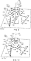
- Figs. 7-11 illustrate portions of a payload engagement system 1000, which is an example of payload engagement system 100 according to the present disclosure.
- vehicle supported portion 102 of payload engagement system 1000 includes insert component 110
- payload mounted portion 104 of payload engagement system 1000 includes receptor component 150.
- payload engagement system 1000 includes securement mechanism 130 with securement engager 132 in the form of a pin.
- Fig. 7 illustrates securement engager 132 in the retracted position
- Fig. 8 illustrates securement engager 132 in the extended position.
- payload engagement system 1000 includes three insert arms 120 and three receptor units 160. Specifically, Fig. 9 illustrates payload engagement system 1000 in the disengaged configuration, while Figs. 10-11 illustrate payload engagement system 1000 in the engaged configuration. More specifically, Fig. 10 illustrates payload engagement system 1000 in the engaged configuration and with securement mechanism 130 in the unlocked configuration, while Fig. 11 illustrates payload engagement system 1000 in the engaged configuration and with securement mechanism 130 in the locked configuration.
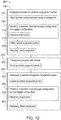
- Fig. 12 is a flowchart depicting methods 200, according to the present disclosure, of transporting a payload with a vehicle.
- a method 200 includes engaging, at 210, a payload (such as payload 50) with a payload engagement system (such as payload engagement system 100); transporting, at 230, the payload with a vehicle (such as vehicle 10); and disengaging, at 250, the payload with the payload engagement system.
- a method 200 includes utilizing a payload engagement system that includes a vehicle supported portion (such as vehicle supported portion 102) that is supported by the vehicle and a payload mounted portion (such as payload mounted portion 104) that is mounted to the payload.
- one of the vehicle supported portion and the payload mounted portion includes and/or is an insert component (such as insert component 110), and the other of the vehicle supported portion and the payload mounted portion includes and/or is a receptor component (such as receptor component 150) such that the insert component is selectively received within the receptor component.
- an insert component such as insert component 110
- a receptor component such as receptor component 150
- the engaging at 210 includes rotating, at 214, the vehicle supported portion with respect to the payload mounted portion to transition the payload engagement system from a disengaged configuration to an engaged configuration.
- the disengaging at 250 includes rotating, at 254, the vehicle supported portion with respect to the payload mounted portion to transition the payload engagement system from the engaged configuration to the disengaged configuration.
- the rotating at 214 and the rotating at 254 may be performed in any appropriate manner.
- the rotating at 214 and/or the rotating at 254 may include rotating the vehicle with respect to the payload to rotate the insert component with respect to the receptor component.
- the vehicle supported portion may be coupled to the vehicle via a rotary element (such as rotary element 24), and the rotating at 214 and/or the rotating at 254 may include rotating the vehicle supported portion with respect to the vehicle with the rotary element to rotate the insert component with respect to the receptor component.
- the rotating at 214 and/or the rotating at 254 may not include rotating the vehicle with respect to the payload mounted portion.
- Methods 200 may be performed with and/or utilize a payload engagement system in which the insert component includes at least two insert arms (such as insert arms 120) and the receptor component includes at least two receptor units (such as receptor units 160). More specifically, each receptor unit may include an antechamber (such as antechamber 170) and a locking chamber (such as locking chamber 180).
- the rotating at 214 may include inserting, at 216, each insert arm into the locking chamber of a respective receptor unit via the antechamber of the respective receptor unit.
- the rotating at 254 may include removing, at 256, each insert arm from the locking chamber of the respective receptor unit via the antechamber of the respective receptor unit.
- the engaging at 210 may include aligning, at 212, the insert component and the receptor component, such as prior to the rotating at 214.
- the aligning at 212 may include aligning along any appropriate dimension, such as vertically aligning and/or axially aligning.
- the aligning at 212 may include aligning such that an insert component central axis (such as insert component central axis 112) and a receptor component central axis (such a receptor component central axis 152) are at least substantially parallel and/or collinear.
- the aligning at 212 may include aligning such that an insert component plane (such as insert component plane 114) and a receptor component plane (such as receptor component plane 154) are at least substantially parallel and/or coplanar.
- the engaging at 210 may include, subsequent to the rotating at 214, lifting, at 218, the vehicle supported portion with respect to the payload mounted portion such that each insert arm is at least partially received in a locking chamber recess (such as locking chamber recess 184) of the locking chamber of the respective receptor unit.
- the lifting at 218 may include lifting such that each insert arm is rotationally constrained within each respective locking chamber. Additionally or alternatively, the lifting at 218 may include lifting such that each insert arm contacts an upper wall (such as upper wall 164) of the respective receptor unit.
- the engaging at 210 additionally includes securing, at 220, the insert component in the engaged configuration via at least one securement mechanism (such as securement mechanism 130).
- the securing at 220 includes transitioning each securement mechanism from an unlocked configuration to a locked configuration, such as to at least partially restrict the payload engagement system from transitioning to the disengaged configuration.
- the lifting at 218 and the securing at 220 may be performed in any appropriate sequence. As examples, the securing at 220 may be performed prior to the lifting at 218, or may be performed subsequent to the lifting at 218.
- the transporting at 230 may be performed in any appropriate manner.
- the transporting at 230 may include transporting such that the receptor component central axis remains at least substantially parallel to a vertical axis (such as vertical axis 106).
- the transporting at 230 may include pivoting, at 232, the vehicle supported portion with respect to the vehicle with a gimbal (such as gimbal 22), such as to maintain the receptor component central axis in an orientation that is at least substantially parallel to the vertical axis.
- the vehicle includes and/or is an aircraft (such as aircraft 11), such as a rotorcraft and/or a UAV
- the aircraft may tilt relative to a ground surface toward a direction in which the aircraft travels.
- the pivoting at 232 may include pivoting the vehicle supported portion with respect to the aircraft such that the payload remains at least substantially upright as the aircraft tilts with respect to the ground surface.
- the disengaging at 250 may be performed in any appropriate manner.
- the disengaging at 250 may include, prior to the rotating at 254, lowering, at 252, the vehicle supported portion with respect to the payload mounted portion.
- the lowering at 252 when performed, includes lowering such that each insert arm is removed from the locking chamber recess of the respective receptor unit, such as to permit the insert arm to rotate with respect to the receptor unit.
- the lowering at 252 may include lowering such that each insert arm contacts a receptor base (such as receptor base 166) of the respective receptor unit.
- the disengaging at 250 additionally may include releasing, at 258, the insert component by transitioning each securement mechanism from the locked configuration to the unlocked configuration.
- the releasing at 258 may include releasing such that the securement mechanism ceases to restrict the payload engagement system from transitioning to the disengaged configuration.
- the lowering at 252 and the releasing at 258 may be performed in any appropriate sequence. As examples, the releasing at 258 may be performed prior to the lowering at 252, or may be performed subsequent to the lowering at 252.
Landscapes
- Engineering & Computer Science (AREA)
- Aviation & Aerospace Engineering (AREA)
- Connection Of Plates (AREA)
Description
- The present disclosure relates to payload engagement systems, vehicles including the same, and related methods.
- Vehicles such as aircraft may be used to deliver payloads to a delivery site. For example, unmanned aerial vehicles (UAVs) may be used to transport packages substantially autonomously. However, such applications generally require human interaction to place a package in the UAV's cargo area and/or to otherwise couple the package to the UAV and/or uncouple the package from the UAV. Such human interaction with a UAV may necessitate the use of special procedures and/or apparatuses to ensure the safety of the human user, especially when the UAV is intended to interact with an untrained human user such as the end recipient of a delivered package. For example, human interaction with a UAV may require the UAV to land and/or power off to couple the package to the UAV and/or to uncouple the package from the UAV, resulting in downtime between delivery runs.
-
US 2017/267347 in the abstract states: "Disclosed is a package delivery mechanism (PDM) of an unmanned aerial vehicle (UAV). The PDM includes a gravity activated locking mechanism to lock and unlock a package attached to the UAV based on the weight of the package. When the package is attached to suspension means of the UAV that lowers the package to the ground from the UAV, the locking mechanism automatically engages with the package and keeps the package locked to the suspension means, due to the weight of the package. When the package is lowered and reaches on the ground, the weight of the package is offloaded from the suspension means, which enables the locking mechanism to be disengaged, thereby releasing the package. The PDM includes a severing module to sever the suspension means from the UAV." -
US 2017/158144 in the abstract states: "An accessory attachment system comprising a fastening key having an accessory retention cap, a stem extending from the retention cap, and at least one bit extending laterally from a distal end of the stem. The stem configured to be inserted through a key aperture in an accessory to be attached to the vehicle. The system includes a locking bracket connectable to the vehicle adjacent an accessory portal provided in the vehicle. The locking bracket comprises a base plate, a keyhole disposed through the base plate, and at least one inclined securing structure disposed along a circumference of the keyhole. Each securing structure comprises a ramp and a detent. The keyhole is configured to receive the stem distal end and bit(s) therethrough, and each securing structure is configured to engage the bit(s) and interlock the fastening key with the locking bracket upon rotation of the key." -
US 2014/353994 in the abstract states: "A latching apparatus for sequentially latching and unlatching two objects is provided. The latching apparatus includes a cylinder attached to the first object and including a first opening, and a second opening laterally disposed to the first opening, a spring loaded piston including a circumferential wall disposed in the first opening, a shank axially extending from the piston and defining a transverse latch pin at an end thereof, and a spring loaded plunger disposed within the second opening. The wall defines a contiguous cam-groove thereon. The cam-groove includes alternating upper and lower nodal points with straight and inclined segments therebetween. The plunger slidably engages the cam-groove to co-operatively execute one or more of a translation, and a rotation of the shank such that the latch pin rotatably extends or retracts into or out of the slotted opening on the locking plate of the second object." -
WO 89/02988 -
DE 10 2016 104418 in the abstract states: "The invention relates to a fastening device (8) for a vehicle (10), in particular an aircraft, with at least one first fastening module (12), which is provided for connection to a structural component (14) of the vehicle (10), and with at least one second fastening module (16) which is provided for attachment of at least one interior trim (18) of the vehicle (10). It is proposed that the fastening device (8) comprises at least one connecting unit (20) which is provided to connect the first fastening module (12) and the second fastening module (16) in an assembled state." -
DE 10 2004 035627 B3 in the abstract states: "The device has an inserting part (2) insertable into a base for coupling construction units, where the inserting part is rotatable around a rotation axis (3). The inserting part exhibits two contact units (4) that interact with a locking mechanism (5) which is attached to the base. The locking mechanism has a movable pin for contacting with the contact units, where the pin is pre-stressed in a direction of the rotation axis." - The present invention is set out in the independent claims, with optional features set out in the claims dependent thereto.
-
-
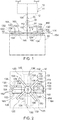
Fig. 1 is a schematic front elevation view representing examples of payload engagement systems according to the present disclosure. -
Fig. 2 is a schematic plan view representing examples of payload engagement systems according to the present disclosure. -
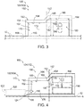
Fig. 3 is a schematic front elevation view representing examples of receptor units according to the present disclosure. -
Fig. 4 is a schematic front elevation view representing an insert arm transitioning from a disengaged configuration to an engaged configuration within a receptor unit according to the present disclosure. -
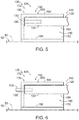
Fig. 5 is a schematic side elevation view representing an insert arm received within a receptor unit and with a securement mechanism in an unlocked configuration according to the present disclosure. -
Fig. 6 is a schematic side elevation view representing the insert arm and receptor unit ofFig. 5 with the securement mechanism in a locked configuration according to the present disclosure. -
Fig. 7 is a side elevation view representing an insert arm with a securement engager in a retracted position according to the present disclosure. -
Fig. 8 is a side elevation view representing the insert arm ofFig. 7 with the securement engager in an extended position according to the present disclosure. -
Fig. 9 is a top perspective view representing a payload engagement system in a disengaged configuration according to the present disclosure. -
Fig. 10 is a top perspective view representing the payload engagement system ofFig. 9 in an engaged configuration according to the present disclosure. -
Fig. 11 is a side perspective view representing a payload engagement system in the locked configuration and with a securement mechanism in a locked configuration according to the present disclosure. -
Fig. 12 is a flowchart depicting methods of transporting a payload with a vehicle according to the present disclosure. -
Figs. 1-12 provide illustrative, non-exclusive examples ofpayload engagement systems 100, ofvehicle 10 including portions ofpayload engagement systems 100, and/or ofmethods 200 of transporting a payload with a vehicle, according to the present disclosure. Elements that serve a similar, or at least substantially similar, purpose are labeled with like numbers in each ofFigs. 1-12 , and these elements may not be discussed in detail herein with reference to each ofFigs. 1-12 . Similarly, all elements may not be labeled in each ofFigs. 1-12 , but reference numerals associated therewith may be utilized herein for consistency. Elements, components, and/or features that are discussed herein with reference to one or more ofFigs. 1-12 may be included in and/or utilized with any ofFigs. 1-12 without departing from the scope of the present claimed invention, which is only defined by the appended claims. - Generally, in the figures, elements that are likely to be included in a given example are illustrated in solid lines, while elements that are optional to a given example are illustrated in dashed lines. However, elements that are illustrated in solid lines are not essential to all examples of the present disclosure, and an element shown in solid lines may be omitted from a particular example without departing from the scope of the present disclosure.
-
Figs. 1-2 are schematic illustrations of examples ofpayload engagement systems 100 and ofpayloads 50 according to the present disclosure.Fig. 1 additionally schematically illustrates an example of avehicle 10 configured to support at least a portion ofpayload engagement system 100 and to carrypayload 50 viapayload engagement system 100. As schematically illustrated inFigs. 1-2 , apayload engagement system 100 for selectively coupling apayload 50 to a vehicle 10 (illustrated inFig. 1 ) includes a vehicle supportedportion 102 configured to be supported byvehicle 10 and a payload mountedportion 104 configured to be mounted onpayload 50. One of vehicle supportedportion 102 and payload mountedportion 104 includes aninsert component 110, and the other of vehicle supportedportion 102 and payload mountedportion 104 includes areceptor component 150. One of payload mountedportion 104 and vehicle supportedportion 102 includes aninsert component 110, and other of payload mountedportion 104 and the vehicle supportedportion 102 includes areceptor component 150.Payload engagement system 100 may be configured to be utilized in conjunction with anyappropriate vehicle 10. For example, and as schematically illustrated inFig .1 ,vehicle 10 may include and/or be anaircraft 11. However, this is not required to allpayload engagement systems 100 according to the present disclosure, and it is additionally within the scope of the present disclosure thatvehicle 10 may include and/or be any appropriate vehicle for carrying a payload, such as a land-based vehicle, a water vehicle, a submersible water vehicle, and/or a space vehicle. - In an embodiment of
payload engagement system 100 configured to be utilized in conjunction withaircraft 11,aircraft 11 may include and/or be any appropriate aircraft. As examples,aircraft 11 may include and/or be a rotorcraft, such as a rotorcraft that includes two rotors, three rotors, four rotors, or more than four rotors. Additionally or alternatively,aircraft 11 may include and/or be an unmanned aerial vehicle (UAV) and/or a drone. As more specific examples,aircraft 11 may be a remotely piloted UAV or may be an autonomously controlled UAV. Utilizingpayload engagement system 100 in conjunction withaircraft 11 in the form of a UAV may facilitate transportingpayload 50, such as a package, with little or no human intervention needed to couplepayload 50 toaircraft 11 or to uncouplepayload 50 fromaircraft 11. Thus, for example, utilizingpayload engagement system 100 in conjunction withaircraft 11 may facilitatecoupling payload 50 toaircraft 11 oruncoupling payload 50 fromaircraft 11 whileaircraft 11 remains in flight, thereby increasing a delivery turnaround speed relative to a system in whichaircraft 11 needs to land and/or power off between delivery runs. -
Vehicle 10 may have any appropriate structure for supportingpayload engagement system 100 and/orpayload 50. For example, and as schematically illustrated inFig. 1 ,vehicle 10 may include avehicle body 12 and further may include asupport structure 20 that extends fromvehicle body 12 to support vehicle supportedportion 102. In such an embodiment,support structure 20 may include agimbal 22 configured to enable vehicle supportedportion 102 to pivot with respect tovehicle body 12. Such a configuration may facilitate maintainingpayload 50 in an upright orientation whilevehicle 10 transportspayload 50 independent of an orientation ofvehicle 10. -
Payload engagement system 100 is configured to transition between a disengaged configuration and an engaged configuration at least partially via rotation ofinsert component 110 with respect toreceptor component 150. As an example,Fig. 2 schematically illustratespayload engagement system 100 in the disengaged configuration in dash-dot lines and schematically illustratespayload engagement system 100 in the engaged configuration in solid and dashed lines.Payload engagement system 100 may be configured such thatinsert component 110 rotates with respect toreceptor component 150 about any appropriate axis. As an example, and as schematically illustrated inFigs. 1-2 ,insert component 110 may have an insert componentcentral axis 112, and insertcomponent 110 may be configured to rotate with respect toreceptor component 150 about insert componentcentral axis 112 whenpayload engagement system 100 transitions between the disengaged configuration and the engaged configuration. Additionally or alternatively, and as additionally schematically illustrated inFigs. 1-2 ,receptor component 150 may have a receptor componentcentral axis 152, and insertcomponent 110 may be configured to rotate with respect toreceptor component 150 about receptor componentcentral axis 152 whenpayload engagement system 100 transitions between the disengaged configuration and the engaged configuration. As another example, and as further schematically illustrated inFigs. 1-2 ,insert component 110 may be configured to rotate with respect toreceptor component 150 about avertical axis 106 whenpayload engagement system 100 transitions between the disengaged configuration and the engaged configuration. - In the engaged configuration,
receptor component 150 receives and engagesinsert component 110 such thatinsert component 110 is rotationally constrained withinreceptor component 150 and such that a weight ofpayload 50 is supported by vehicle supportedportion 102. Stated differently, whenpayload engagement system 100 is in the engaged configuration,receptor component 150 engagesinsert component 110 such thatvehicle 10 is enabled to lift payload mountedportion 104, and hencepayload 50, via vehicle supportedportion 102. In this manner, the engagement betweeninsert component 110 andreceptor component 150 enablesvehicle 10 to carrypayload 50 whenpayload engagement system 100 is in the engaged configuration. As more specific examples,payload engagement system 100 may be configured to support a payload weight that is at least 10 Newtons (N), at least 30 N, at least 50 N, at least 100 N, at least 300 N, at least 500 N, at most 1000 N, at most 700 N, at most 200 N, at most 70 N, and/or at most 20 N while the vehicle carriespayload 50. The rotational constraint ofinsert component 110 withinreceptor component 150 whenpayload engagement system 100 is in the engaged configuration restrictspayload engagement system 100 from transitioning to the disengaged configuration whilevehicle 10 carriespayload 50. -
Payload engagement system 100 is configured to rotateinsert component 110 with respect toreceptor component 150 in any appropriate manner. As an example,payload engagement system 100 may be configured to transition between the disengaged configuration and the engaged configuration via rotation ofvehicle 10 with respect topayload 50 about insert componentcentral axis 112 and/or receptor componentcentral axis 152. Additionally or alternatively, and as schematically illustrated inFig. 1 ,support structure 20 may include arotary element 24 configured to rotate vehicle supportedportion 102 with respect tovehicle body 12 and about insert componentcentral axis 112 and/or receptor componentcentral axis 152. In such an embodiment,vehicle 10 may not rotate with respect topayload 50 whilepayload engagement system 100 transitions between the disengaged configuration and the engaged configuration. By contrast, in an embodiment that lacksrotary element 24, transitioningpayload engagement system 100 between the disengaged configuration and the engaged configuration may require and/or correspond to a rotation ofvehicle 10 and/orvehicle body 12 with respect topayload 50. Stated differently, in an embodiment that lacksrotary element 24, transitioningpayload engagement system 100 between the disengaged configuration and the engaged configuration may require and/or correspond tovehicle body 12 and vehicle supportedportion 102 rotating at least substantially in unison. - In some examples of
payload engagement system 100,payload engagement system 100 is configured to transition between the disengaged configuration and the engaged configuration via translation ofinsert component 110 with respect toreceptor component 150 along (i.e., in a direction parallel to)vertical axis 106. In such an example, the rotation ofinsert component 110 with respect toreceptor component 150 and the translation alongvertical axis 106 may take place sequentially. As a more specific example,payload engagement system 100 may be configured to transition from the disengaged configuration to the engaged configuration via upward translation of vehicle supportedportion 102 with respect to payload mountedportion 104 alongvertical axis 106 subsequent to rotation ofinsert component 110 with respect toreceptor component 150. Similarly,payload engagement system 100 may be configured to transition from the engaged configuration to the disengaged configuration via downward translation of vehicle supportedportion 102 with respect to payload mountedportion 104 alongvertical axis 106 prior to rotation ofinsert component 110 with respect toreceptor component 150. In some examples of such an embodiment, the upward translation of vehicle supportedportion 102 with respect to payload mountedportion 104 causes insertcomponent 110 to be rotationally constrained withinreceptor component 150, and the downward translation of vehicle supportedportion 102 with respect to payload mountedportion 104 causes insertcomponent 110 to be free to rotate with respect toreceptor component 150. -
Insert component 110 andreceptor component 150 may have any appropriate structure such thatinsert component 110 is selectively received withinreceptor component 150 as described herein. For example, and as schematically illustrated inFigs. 1-2 ,insert component 110 includes at least two insertarms 120, andreceptor component 150 may include at least tworeceptor units 160 corresponding to the at least two insertarms 120. As more specific examples,insert component 110 includes three insertarms 120.. Similarly,receptor component 150 may includes threereceptor units 160. As a more specific example,payload engagement system 100,insert component 110 includes three insertarms 120 andreceptor component 150 includes threereceptor units 160. Such a configuration may produce a more stable and/or secure engagement betweeninsert component 110 andreceptor component 150 relative to an otherwise identicalpayload engagement system 100 that includesfewer insert arms 120 and/orfewer receptor units 160. Such a configuration additionally may have a smaller weight and/or materials cost, and/or may permit a less strict manufacturing tolerance, relative to an otherwise identicalpayload engagement system 100 that includesmore insert arms 120 and/ormore receptor units 160. For example, an embodiment ofpayload engagement system 100 in which insertcomponent 110 engagesreceptor component 150 at more than three points of contact (e.g., the points at which more than three insertarms 120 engage more than three respective receptor units 160) may require precise manufacturing tolerances to ensure that eachinsert arm 120 remains in contact with arespective receptor unit 160 whilevehicle 10 carriespayload 50. By contrast, an embodiment ofpayload engagement system 100 in which insertcomponent 110 engagesreceptor component 150 at three points of contact (e.g., the points at which three insertarms 120 engage three respective receptor units 160) may facilitate consistent contact between eachinsert arm 120 and eachcorresponding receptor unit 160 independent of slight variations in the positions ofinsert arms 120 and/orreceptor units 160 relative to a manufacturing specification. - In the examples of
payload engagement system 100 illustrated inFigs. 1-2 and9-11 , the number ofinsert arms 120 is equal to the number ofreceptor units 160. Eachreceptor unit 160 may be configured to be coupled to and/or mounted topayload 50 in any appropriate manner. For example, and as schematically illustrated inFigs. 1-2 , eachreceptor unit 160 may be configured to be mounted on anupper surface 52 ofpayload 50, such as a generally planarupper surface 52. In some examples ofpayload engagement system 100 that include insertarms 120 andreceptor units 160, eachinsert arm 120 is removed from a correspondingreceptor unit 160 whenpayload engagement system 100 is in the disengaged configuration, and is received within the correspondingreceptor unit 160 whenpayload engagement system 100 is in the engaged configuration. -
Payload engagement system 100 may be configured to transition between the disengaged configuration and the engaged configuration upon axial and/or vertical alignment ofinsert component 110 andreceptor component 150. For example, and as schematically illustrated inFigs. 1-2 , in some embodiments ofpayload engagement system 100, insertarms 120 are distributed about, and/or extend radially from, insert componentcentral axis 112 ofinsert component 110, andreceptor units 160 are distributed about receptor componentcentral axis 152 ofreceptor component 150. In some examples of such an embodiment, insert componentcentral axis 112 and receptor componentcentral axis 152 are at least substantially parallel and/or at least substantially collinear whenpayload engagement system 100 transitions between the disengaged configuration and the engaged configuration. As another example, and as schematically illustrated inFigs. 1-2 , in some embodiments ofpayload engagement system 100, eachinsert arm 120 extends within aninsert component plane 114 ofinsert component 110, and eachreceptor unit 160 is positioned within areceptor component plane 154 ofreceptor component 150. In some examples of such an embodiment,insert component plane 114 andreceptor component plane 154 are at least substantially parallel and/or at least substantially coplanar whenpayload engagement system 100 transitions between the disengaged configuration and the engaged configuration. -
Fig. 3 schematically illustrates examples ofreceptor units 160, andFig. 4 schematically illustrates an example of a spatial relationship betweenreceptor unit 160 and insertarm 120 whilepayload engagement system 100 is transitioned from the disengaged configuration to the engaged configuration. As schematically illustrated inFigs. 3-4 ,receptor unit 160 generally includes and/or is at least partially defined by at least oneside wall 162 and at least oneupper wall 164.Receptor unit 160 additionally may include areceptor base 166 that extends fromupper surface 52 ofpayload 50 whenreceptor unit 160 is mounted onpayload 50. In such an embodiment,receptor unit 160 may be mounted topayload 50 viareceptor base 166, such as by affixing, adhering, and/or mechanically connectingreceptor base 166 toupper surface 52. However, this is not required to all examples ofpayload engagement system 100 according to the present disclosure, and it is additionally within the scope of the present disclosure thatreceptor unit 160 may lackreceptor base 166, and or may be mounted topayload 50 via at least oneside wall 162. - In some examples of an embodiment of
receptor unit 160 that includesreceptor base 166, and as schematically illustrated inFigs. 3-4 ,receptor unit 160 additionally includes aramp portion 168 that extends betweenupper surface 52 ofpayload 50 andreceptor base 166 whenreceptor unit 160 is mounted onpayload 50. More specifically, when present,ramp portion 168 extends oblique toupper surface 52, such as to facilitateinsert arm 120 enteringreceptor unit 160 whenpayload engagement system 100 transitions from the disengaged configuration to the engaged configuration. As a more specific example, and as schematically illustrated inFig. 4 , insertarm 120 may include aninsert arm base 124 such thatramp portion 168 is configured to engageinsert arm base 124 to at least partially guideinsert arm 120 intoreceptor unit 160 whenpayload engagement system 100 is transitioned from the disengaged configuration to the engaged configuration. As a more specific example, and as additionally schematically illustrated inFig. 4 , insertarm base 124 may be at least partially rounded, such as to facilitateinsert arm base 124 entering and/or exitingreceptor unit 160 via contact withramp portion 168. -
Receptor unit 160 may have any appropriate form and/or structure for receivinginsert arm 120. For example, and as schematically illustrated inFigs. 3-4 , some examples ofreceptor unit 160 include and/or define anantechamber 170 and alocking chamber 180. In such an embodiment, and as schematically illustrated inFig. 3 ,antechamber 170 may be characterized by anantechamber height 172, and lockingchamber 180 may be characterized by a locking chamber height 182 that is greater thanantechamber height 172. In some examples of such an embodiment,upper wall 164 ofreceptor unit 160 includes atransition region 165 betweenantechamber 170 and lockingchamber 180, such thatupper wall 164 is ramped and/or smoothly curved withintransition region 165. -
Antechamber height 172 and/or locking chamber height 182 may be measured in any appropriate manner. For example, in an embodiment in whichreceptor unit 160 includesreceptor base 166,antechamber height 172 may be measured betweenreceptor base 166 andupper wall 164 inantechamber 170 and in a direction parallel to receptor componentcentral axis 152. Similarly, in such an embodiment, locking chamber height 182 may be measured betweenreceptor base 166 andupper wall 164 in lockingchamber 180 and in the direction parallel to receptor componentcentral axis 152. Alternatively, in an embodiment in whichreceptor unit 160 lacksreceptor base 166,antechamber height 172 may be measured betweenupper surface 52 ofpayload 50 andupper wall 164 inantechamber 170 and in the direction parallel to receptor componentcentral axis 152 whenreceptor unit 160 is mounted toupper surface 52. Similarly, in such an embodiment, locking chamber height 182 may be measured betweenupper surface 52 ofpayload 50 andupper wall 164 in lockingchamber 180 and in the direction parallel to receptor componentcentral axis 152 whenreceptor unit 160 is mounted toupper surface 52. -
Antechamber height 172 and locking chamber height 182 may be any appropriate respective heights, such as relative to a dimension ofinsert arm 120. For example, and as schematically illustrated inFig. 4 , insertarm 120 may have and/or be characterized by aninsert arm height 122, as measured in a direction parallel to insert componentcentral axis 112, andantechamber height 172 and/or locking chamber height 182 each may be at least 100% ofinsert arm height 122, at least 120% ofinsert arm height 122, at least 140% ofinsert arm height 122, at least 160% ofinsert arm height 122, at least 180% ofinsert arm height 122, at most 200% ofinsert arm height 122, at most 170% ofinsert arm height 122, at most 150% ofinsert arm height 122, at most 130% ofinsert arm height 122, and/or at most 110% ofinsert arm height 122. - In an embodiment of
receptor unit 160 that includesantechamber 170 and lockingchamber 180, and as schematically illustrated inFig. 4 ,receptor unit 160 generally is configured such thatinsert arm 120 passes throughantechamber 170 whenpayload engagement system 100 is transitioned between the disengaged configuration and the engaged configuration. As examples, in such an embodiment,insert arm 120 passes throughantechamber 170 and subsequently enters lockingchamber 180 whenpayload engagement system 100 transitions from the disengaged configuration to the engaged configuration, and insertarm 120 passes throughantechamber 170 and subsequently exitsreceptor unit 160 when payload engagement system transitions from the engaged configuration to the disengaged configuration. - In an embodiment of
receptor unit 160 that includesantechamber 170 and lockingchamber 180, lockingchamber 180 generally is configured such that acorresponding insert arm 120 is received in lockingchamber 180 whenpayload engagement system 100 is in the engaged configuration. More specifically, and as schematically illustrated inFig. 4 , in an embodiment in which locking chamber height 182 is greater thanantechamber height 172, lockingchamber 180 may be described as including alocking chamber recess 184 configured to at least partially receiveinsert arm 120 whenpayload engagement system 100 is in the engaged configuration. Lockingchamber recess 184 may be at least partially defined byside wall 162,upper wall 164, and/ortransition region 165. In such an embodiment, lockingchamber 180 and/or lockingchamber recess 184 at least partially restrictsinsert arm 120 from moving within lockingchamber 180 and/or rotating (such as about insert component central axis 112) whenpayload engagement system 100 is in the engaged configuration. More specifically, whenpayload engagement system 100 is in the engaged configuration,insert arm 120 is at least partially restricted from moving within lockingchamber 180 by lockingchamber recess 184,side wall 162,upper wall 164, and/ortransition region 165. In this manner, lockingchamber 180 and/or lockingchamber recess 184 may facilitate maintainingpayload engagement system 100 in the engaged configuration whilevehicle 10 carriespayload 50. - Locking
chamber recess 184 may have any appropriate dimension, such as to securely receiveinsert arm 120 and/or to securely restrict motion ofinsert arm 120. For example, and as schematically illustrated inFig. 3 , lockingchamber recess 184 may have and/or be characterized by arecess depth 186 that is at least 10% of locking chamber height 182, at least 20% of locking chamber height 182, at least 30% of locking chamber height 182, at least 40% of locking chamber height 182, at least 50% of locking chamber height 182, at most 55% of locking chamber height 182, at most 45% of locking chamber height 182, at most 35% of locking chamber height 182, at most 25% of locking chamber height 182, and/or at most 15% of locking chamber height 182. Additionally or alternatively,recess depth 186 may describe and/or correspond to a difference between locking chamber height 182 andantechamber height 172. - When
payload engagement system 100 is in the engaged configuration,insert arm 120 may be restricted from exiting lockingchamber 180 in any appropriate manner. As an example, asvehicle 10 carriespayload 50, a force of gravity may at least partially retaininsert arm 120 within lockingchamber recess 184 by restrictinginsert arm 120 from translating vertically downward with respect to lockingchamber recess 184, as may be required forinsert arm 120 to exit locking chamber 180 (and hence receptor unit 160). Additionally or alternatively, and as schematically illustrated inFigs. 1-2 and4-6 ,insert component 110 may include asecurement mechanism 130 configured to at least partially restrictpayload engagement system 100 from transitioning from the engaged configuration to the disengaged configuration. More specifically, when present,securement mechanism 130 includes asecurement engager 132 and asecurement receiver 190 configured to selectively receivesecurement engager 132 to at least partially restrictpayload engagement system 100 from transitioning from the engaged configuration to the disengaged configuration. When present,securement mechanism 130 is configured to be selectively transitioned between an unlocked configuration and a locked configuration. Specifically, in the unlocked configuration,securement mechanism 130 does not restrictpayload engagement system 100 from transitioning from the engaged configuration to the disengaged configuration, whereas in the locked configuration,securement mechanism 130 at least partially restrictspayload engagement system 100 from transitioning from the engaged configuration to the disengaged configuration. -
Securement mechanism 130 is incorporated intopayload engagement system 100 in any appropriate manner. According to the invention, in thepayload engagement system 100,insert component 110 includessecurement engager 132, andreceptor component 150 includessecurement receiver 190. More specifically, at least oneinsert arm 120 may includesecurement engager 132, and at least one correspondingreceptor unit 160 may includesecurement receiver 190. For example,securement receiver 190 may be defined byside wall 162,upper wall 164, and/orreceptor base 166 ofreceptor unit 160. In such an embodiment,securement receiver 190 receivessecurement engager 132 to at least partially restrictpayload engagement system 100 from transitioning from the engaged configuration to the disengaged configuration. -
Securement mechanism 130,securement engager 132, and/orsecurement receiver 190 have an appropriate structure.Securement engager 132 includes a pin.Securement receiver 190 includes a hole.Securement receiver 190 is configured to receivesecurement engager 132 in an appropriate manner.Securement engager 132 extends throughsecurement receiver 190 and may engagesecurement receiver 190 whensecurement mechanism 130 is in the locked configuration. -
Fig. 3 schematically illustrates examples ofsecurement receiver 190 in the form of a circular hole (dashed lines inFig. 3 ) and a vertical slot (dash-dot lines inFig. 3 ), whileFig. 4 schematically illustrates an example ofsecurement receiver 190 in the form of a circular hole. In an embodiment ofsecurement mechanism 130 in whichsecurement receiver 190 takes the form of a hole, and as schematically illustrated inFig. 4 ,securement mechanism 130 may be configured to transition between the unlocked configuration and the locked configuration only wheninsert arm 120 is received within lockingchamber recess 184. Alternatively, in an embodiment ofsecurement mechanism 130 in whichsecurement receiver 190 takes the form of a vertical slot,securement receiver 190 may permitsecurement engager 132 to translate vertically withinsecurement receiver 190. Such an embodiment may permitsecurement mechanism 130 to be transitioned between the unlocked configuration and the locked configuration wheninsert arm 120 is in lockingchamber 180, regardless of whetherinsert arm 120 is in lockingchamber recess 184. -
Fig. 5 schematically illustrates an example of a portion ofpayload engagement system 100 withsecurement mechanism 130 in the unlocked configuration, andFig. 6 schematically illustrates the portion ofpayload engagement system 100 ofFig. 5 withsecurement mechanism 130 in the locked configuration. As shown in the example ofFigs. 5-6 ,securement engager 132 takes the form of a pin andsecurement receiver 190 takes the form of a hole such thatsecurement engager 132 extends throughsecurement receiver 190 whensecurement mechanism 130 is in the locked configuration. As schematically illustrated inFigs. 5-6 ,securement engager 132 may be described as being in an extended position whensecurement mechanism 130 is in the locked configuration (Fig. 6 ), and may be described as being in a retracted position whensecurement mechanism 130 is in the unlocked configuration (Fig. 5 ).Securement engager 132 may be biased toward the extended position, may be biased toward the retracted position, or may not be biased toward either of the extended position and the retracted position. - As further schematically illustrated in
Figs. 5-6 ,securement mechanism 130 additionally includessecurement mechanism actuator 134 configured to transition eachsecurement engager 132 between the extended position and the retracted position.Securement mechanism actuator 134 is configured to transition a correspondingsecurement engager 132 between the extended position and the retracted position. For example, in an embodiment ofsecurement mechanism 130 that includes more than onesecurement engager 132, eachsecurement engager 132 may be transitioned between the extended position and the retracted position by a unique correspondingsecurement mechanism actuator 134. Alternatively, in an embodiment ofsecurement mechanism 130 that includes more than onesecurement engagers 132,securement mechanism actuator 134 may be configured to transition each of a plurality ofcorresponding securement engagers 132 between the extended position and the retracted position.Securement mechanism actuator 134 may include and/or be any appropriate mechanism for selectively transitioningsecurement engager 132 between the extended position and the retracted position. As examples,securement mechanism actuator 134 may include and/or be a motor, a servomotor, a screw drive motor, a pneumatic actuator, and/or a hydraulic actuator. -
Figs. 7-11 illustrate portions of apayload engagement system 1000, which is an example ofpayload engagement system 100 according to the present disclosure. Specifically, in the example ofFigs. 7-11 , vehicle supportedportion 102 ofpayload engagement system 1000 includesinsert component 110, and payload mountedportion 104 ofpayload engagement system 1000 includesreceptor component 150. As seen inFigs. 7-8 ,payload engagement system 1000 includessecurement mechanism 130 withsecurement engager 132 in the form of a pin. Specifically,Fig. 7 illustratessecurement engager 132 in the retracted position, andFig. 8 illustratessecurement engager 132 in the extended position. - As seen in
Figs. 9-11 ,payload engagement system 1000 includes three insertarms 120 and threereceptor units 160. Specifically,Fig. 9 illustratespayload engagement system 1000 in the disengaged configuration, whileFigs. 10-11 illustratepayload engagement system 1000 in the engaged configuration. More specifically,Fig. 10 illustratespayload engagement system 1000 in the engaged configuration and withsecurement mechanism 130 in the unlocked configuration, whileFig. 11 illustratespayload engagement system 1000 in the engaged configuration and withsecurement mechanism 130 in the locked configuration. -
Fig. 12 is aflowchart depicting methods 200, according to the present disclosure, of transporting a payload with a vehicle. As shown inFig. 12 , amethod 200 includes engaging, at 210, a payload (such as payload 50) with a payload engagement system (such as payload engagement system 100); transporting, at 230, the payload with a vehicle (such as vehicle 10); and disengaging, at 250, the payload with the payload engagement system. Specifically, amethod 200 includes utilizing a payload engagement system that includes a vehicle supported portion (such as vehicle supported portion 102) that is supported by the vehicle and a payload mounted portion (such as payload mounted portion 104) that is mounted to the payload. More specifically, one of the vehicle supported portion and the payload mounted portion includes and/or is an insert component (such as insert component 110), and the other of the vehicle supported portion and the payload mounted portion includes and/or is a receptor component (such as receptor component 150) such that the insert component is selectively received within the receptor component. - The engaging at 210 includes rotating, at 214, the vehicle supported portion with respect to the payload mounted portion to transition the payload engagement system from a disengaged configuration to an engaged configuration. Similarly, the disengaging at 250 includes rotating, at 254, the vehicle supported portion with respect to the payload mounted portion to transition the payload engagement system from the engaged configuration to the disengaged configuration. The rotating at 214 and the rotating at 254 may be performed in any appropriate manner. For example, the rotating at 214 and/or the rotating at 254 may include rotating the vehicle with respect to the payload to rotate the insert component with respect to the receptor component. Additionally or alternatively, the vehicle supported portion may be coupled to the vehicle via a rotary element (such as rotary element 24), and the rotating at 214 and/or the rotating at 254 may include rotating the vehicle supported portion with respect to the vehicle with the rotary element to rotate the insert component with respect to the receptor component. In such an embodiment, the rotating at 214 and/or the rotating at 254 may not include rotating the vehicle with respect to the payload mounted portion.
-
Methods 200 may be performed with and/or utilize a payload engagement system in which the insert component includes at least two insert arms (such as insert arms 120) and the receptor component includes at least two receptor units (such as receptor units 160). More specifically, each receptor unit may include an antechamber (such as antechamber 170) and a locking chamber (such as locking chamber 180). In such an embodiment, and as indicated inFig. 12 , the rotating at 214 may include inserting, at 216, each insert arm into the locking chamber of a respective receptor unit via the antechamber of the respective receptor unit. Similarly, in such an embodiment, and as further indicated inFig. 12 , the rotating at 254 may include removing, at 256, each insert arm from the locking chamber of the respective receptor unit via the antechamber of the respective receptor unit. - As indicated in
Fig. 12 , the engaging at 210 may include aligning, at 212, the insert component and the receptor component, such as prior to the rotating at 214. The aligning at 212 may include aligning along any appropriate dimension, such as vertically aligning and/or axially aligning. For example, the aligning at 212 may include aligning such that an insert component central axis (such as insert component central axis 112) and a receptor component central axis (such a receptor component central axis 152) are at least substantially parallel and/or collinear. Additionally or alternatively, the aligning at 212 may include aligning such that an insert component plane (such as insert component plane 114) and a receptor component plane (such as receptor component plane 154) are at least substantially parallel and/or coplanar. - As additionally indicated in
Fig. 12 , the engaging at 210 may include, subsequent to the rotating at 214, lifting, at 218, the vehicle supported portion with respect to the payload mounted portion such that each insert arm is at least partially received in a locking chamber recess (such as locking chamber recess 184) of the locking chamber of the respective receptor unit. The lifting at 218 may include lifting such that each insert arm is rotationally constrained within each respective locking chamber. Additionally or alternatively, the lifting at 218 may include lifting such that each insert arm contacts an upper wall (such as upper wall 164) of the respective receptor unit. - As further indicated in
Fig. 12 , the engaging at 210 additionally includes securing, at 220, the insert component in the engaged configuration via at least one securement mechanism (such as securement mechanism 130). The securing at 220 includes transitioning each securement mechanism from an unlocked configuration to a locked configuration, such as to at least partially restrict the payload engagement system from transitioning to the disengaged configuration. The lifting at 218 and the securing at 220 may be performed in any appropriate sequence. As examples, the securing at 220 may be performed prior to the lifting at 218, or may be performed subsequent to the lifting at 218. - The transporting at 230 may be performed in any appropriate manner. For example, the transporting at 230 may include transporting such that the receptor component central axis remains at least substantially parallel to a vertical axis (such as vertical axis 106). As a more specific example, and as indicated in
Fig. 12 , the transporting at 230 may include pivoting, at 232, the vehicle supported portion with respect to the vehicle with a gimbal (such as gimbal 22), such as to maintain the receptor component central axis in an orientation that is at least substantially parallel to the vertical axis. As a more specific example, in an embodiment in which the vehicle includes and/or is an aircraft (such as aircraft 11), such as a rotorcraft and/or a UAV, the aircraft may tilt relative to a ground surface toward a direction in which the aircraft travels. In such an embodiment, the pivoting at 232 may include pivoting the vehicle supported portion with respect to the aircraft such that the payload remains at least substantially upright as the aircraft tilts with respect to the ground surface. - The disengaging at 250 may be performed in any appropriate manner. For example, and with continued reference to
Fig. 12 , the disengaging at 250 may include, prior to the rotating at 254, lowering, at 252, the vehicle supported portion with respect to the payload mounted portion. Specifically, the lowering at 252, when performed, includes lowering such that each insert arm is removed from the locking chamber recess of the respective receptor unit, such as to permit the insert arm to rotate with respect to the receptor unit. The lowering at 252 may include lowering such that each insert arm contacts a receptor base (such as receptor base 166) of the respective receptor unit. - As further indicated in
Fig. 12 , in an embodiment in which the insert component includes at least one securement mechanism, the disengaging at 250 additionally may include releasing, at 258, the insert component by transitioning each securement mechanism from the locked configuration to the unlocked configuration. The releasing at 258 may include releasing such that the securement mechanism ceases to restrict the payload engagement system from transitioning to the disengaged configuration. The lowering at 252 and the releasing at 258 may be performed in any appropriate sequence. As examples, the releasing at 258 may be performed prior to the lowering at 252, or may be performed subsequent to the lowering at 252.
Claims (13)
- A payload engagement system [100] to selectively couple a payload [50] to a vehicle [10], the payload engagement system [100] comprising:a vehicle supported portion [102] configured to be supported by the vehicle [10]; anda payload mounted portion [104] configured to be mounted on the payload [50];wherein one of the vehicle supported portion [102] and the payload mounted portion [104] includes an insert component [110]; wherein the other of the vehicle supported portion [102] and the payload mounted portion [104] includes a receptor component [150]; wherein the payload engagement system [100] is configured to transition between a disengaged configuration and an engaged configuration at least partially via rotation of the insert component [110] with respect to the receptor component [150]; and wherein, in the engaged configuration, the receptor component [150] receives the insert component [110] and engages the insert component [110] such that the insert component [110] is rotationally constrained within the receptor component [150] to enable the vehicle [10] to carry the payload [50]; wherein the insert component [110] includes at least two insert arms [120], and wherein the receptor component [150] includes at least two receptor units [160] corresponding to the at least two insert arms [120]; and wherein the payload engagement system further includes a securement mechanism (130), wherein the securement mechanism includes at least one securement engager (132) and at least one securement receiver (190), wherein the insert component [110] includes the at least one securement engager [132], wherein the receptor component [150] includes the at least one securement receiver [190], and wherein each securement receiver of the at least one securement receiver is configured to selectively receive a corresponding securement engager of the at least one securement engager when the payload engagement system is in the engaged configuration to at least partially restrict the payload engagement system from transitioning from the engaged configuration to the disengaged configuration; wherein the at least one securement engager comprises a pin and the at least one securement receiver comprises a hole and in which the securement engager is configured to extend, and not extend through the securement receiver in respective locked and unlocked positions, and in which the securement mechanism further comprises a securement mechanism actuator (134) configured to transition each securement engager between the unlocked position and the locked position.
- The payload engagement system [100] of claim 1, wherein the vehicle supported portion [102] includes the insert component [110] and the payload mounted portion [104] includes the receptor component [150].
- The payload engagement system [100] of any of claims 1 to 2, wherein the payload engagement system [100] further is configured to transition between the disengaged configuration and the engaged configuration via translation of the insert component [110] with respect to the receptor component [150] along a vertical axis [106].
- The payload engagement system [100] of any of claims 1 to 3, wherein the at least two insert arms [120] are distributed about an insert component central axis [112] of the insert component [110]; wherein the at least two receptor units [160] are distributed about a receptor component central axis [152] of the receptor component [150]; wherein each insert arm [120] extends radially from the insert component central axis [112]; and wherein the insert component central axis [112] and the receptor component central axis [152] are at least substantially parallel when the payload engagement system [100] transitions between the disengaged configuration and the engaged configuration.
- The payload engagement system [100] of any one claims 1 to 3, wherein each receptor unit [160] includes a ramp portion [168] configured to facilitate a corresponding insert arm [120] entering the receptor unit [160], and wherein the ramp portion [168] extends between an upper surface [52] of the payload [50] and a receptor base [166] of the receptor unit [160] and oblique to the upper surface [52].
- The payload engagement system [100] of any of claims 1 to 3, wherein each receptor unit [160] includes an antechamber [170] and a locking chamber [180]; wherein the antechamber [170] has an antechamber height [172]; wherein the locking chamber [180] has a locking chamber height [182]; wherein the locking chamber height [182] is greater than the antechamber height [172]; and wherein a corresponding insert arm [120] is received in the locking chamber [180] when the payload engagement system [100] is in the engaged configuration.
- The payload engagement system [100] of any of claims 1 to 3, wherein the securement mechanism [130] is configured to be selectively transitioned between an unlocked configuration, in which the securement mechanism [130] does not restrict the payload engagement system [100] from transitioning from the engaged configuration to the disengaged configuration, and a locked configuration, in which the securement mechanism [130] at least partially restricts the payload engagement system [100] from transitioning from the engaged configuration to the disengaged configuration, wherein each securement engager [132] of the at least one securement engager [132] extends through a corresponding securement receiver [190] of the at least one securement receiver [190] when the securement mechanism [130] is in the locked configuration.
- A vehicle [10] including the payload engagement system [100] of any of claims 1 to 7, the vehicle [10] configured to transport a payload [50], wherein the vehicle [10] includes the vehicle supported portion [102] of the payload engagement system [100] of claim 1, wherein the vehicle [10] is an unmanned aerial vehicle (UAV).
- The vehicle [10] including the payload engagement system [100] of claim 8, wherein the vehicle [10] includes a vehicle body [12], wherein the vehicle [10] additionally includes a support structure [20] that extends from the vehicle body [12] and supports the vehicle supported portion [102] of the payload engagement system [100], and wherein the support structure [20] includes a rotary element [24] configured to rotate the vehicle supported portion [102] about at least one of an insert component central axis [112] and a receptor component central axis [152] and with respect to the vehicle body [12].
- A method [200] of transporting a payload [50] with a vehicle [10], the method [200] comprising:engaging [210] the payload [50] with a payload engagement system [100];transporting [230] the payload [50] with the vehicle [10]; anddisengaging [250] the payload [50] with the payload engagement system [100];wherein the payload engagement system [100] includes:a vehicle supported portion [102] configured to be supported by the vehicle [10]; anda payload mounted portion [104] configured to be mounted on the payload [50];wherein the engaging [210] includes rotating [214] the vehicle supported portion [102] with respect to the payload mounted portion [104] to transition the payload engagement system [100] from a disengaged configuration to an engaged configuration; and wherein the disengaging [250] includes rotating [254] the vehicle supported portion [102] with respect to the payload mounted portion [104] to transition the payload engagement system [100] from the engaged configuration to the disengaged configuration; wherein the payload engagement system [100] includes a securement mechanism [130], wherein the securement mechanism [130] includes a securement engager [132] and a securement receiver [190]; wherein one of the vehicle supported portion [102] and the payload mounted portion [104] includes an insert component [110]; wherein the other of the vehicle supported portion [102] and the payload mounted portion [104] includes a receptor component [150]; wherein the insert component [110] includes at least two insert arms [120], and wherein the receptor component [150] includes at least two receptor units [160] corresponding to the at least two insert arms [120]; and wherein the insert component [110] includes the securement engager [132]; wherein the receptor component [150] includes the securement receiver [190]; wherein the securement engager [132] is configured to engage the securement receiver [190] when the payload engagement system [100] is in the engaged configuration to at least partially restrict the payload engagement system [100] from transitioning from the engaged configuration to the disengaged configuration; and wherein the at least one securement engager comprises a pin and the at least one securement receiver comprises a hole and in which the securement engager is configured to extend, and not extend through the securement receiver in respective locked and unlocked positions, and in which the securement mechanism further comprises a securement mechanism actuator (134) configured to transition each securement engager between the unlocked position and the locked position.
- The method [200] of claim 10, wherein each receptor unit [160] includes an antechamber [170] and a locking chamber [180]; wherein the antechamber [170] has an antechamber height [172]; wherein the locking chamber [180] has a locking chamber height [182]; wherein the locking chamber height [182] is greater than the antechamber height [172]; and wherein the rotating [214] the vehicle supported portion [102] with respect to the payload mounted portion [104] to transition the payload engagement system [100] from the disengaged configuration to the engaged configuration includes inserting [216] each insert arm [120] into the locking chamber [180] of a respective receptor unit [160] via a respective antechamber [170] of the respective receptor unit [160].
- The method [200] of any of claims 10 to 11, wherein the engaging [210] includes, subsequent to the rotating [214] the vehicle supported portion [102] with respect to the payload mounted portion [104] to transition the payload engagement system [100] from the disengaged configuration to the engaged configuration, lifting the vehicle supported portion [102] with respect to the payload mounted portion [104] such that each insert arm [120] is at least partially received in a locking chamber recess [184] of the locking chamber [180] of the respective receptor unit [160], and wherein the disengaging [250] includes, prior to the rotating [254] the vehicle supported portion [102] with respect to the payload mounted portion [104] to transition the payload engagement system [100] from the engaged configuration to the disengaged configuration, lowering the vehicle supported portion [102] with respect to the payload mounted portion [104] such that each insert arm [120] is removed from the locking chamber recess [184] of the locking chamber [180] of the respective receptor unit [160].
- The method [200] of any of claims 10 to 12, wherein the securement mechanism [130] is configured to be selectively transitioned between an unlocked configuration, in which the securement mechanism [130] does not restrict the payload engagement system [100] from transitioning from the engaged configuration to the disengaged configuration, and a locked configuration, in which the securement mechanism [130] at least partially restricts the payload engagement system [100] from transitioning from the engaged configuration to the disengaged configuration; and wherein the engaging [210] includes securing [220] the insert component [110] in the engaged by transitioning the securement mechanism [130] from the unlocked configuration to the locked configuration.
Applications Claiming Priority (1)
| Application Number | Priority Date | Filing Date | Title |
|---|---|---|---|
| US15/954,426 US10814983B2 (en) | 2018-04-16 | 2018-04-16 | Payload engagement systems, vehicles including the same, and related methods |
Publications (2)
| Publication Number | Publication Date |
|---|---|
| EP3556654A1 EP3556654A1 (en) | 2019-10-23 |
| EP3556654B1 true EP3556654B1 (en) | 2022-01-05 |
Family
ID=66041156
Family Applications (1)
| Application Number | Title | Priority Date | Filing Date |
|---|---|---|---|
| EP19165955.6A Active EP3556654B1 (en) | 2018-04-16 | 2019-03-28 | Payload engagement systems, vehicles including the same, and related methods |
Country Status (5)
| Country | Link |
|---|---|
| US (1) | US10814983B2 (en) |
| EP (1) | EP3556654B1 (en) |
| JP (1) | JP7312595B2 (en) |
| CN (1) | CN110386251B (en) |
| CA (1) | CA3036873C (en) |
Families Citing this family (4)
| Publication number | Priority date | Publication date | Assignee | Title |
|---|---|---|---|---|
| US10814983B2 (en) * | 2018-04-16 | 2020-10-27 | The Boeing Company | Payload engagement systems, vehicles including the same, and related methods |
| FR3107096B1 (en) * | 2020-02-11 | 2022-01-07 | Airbus Sas | Assembly comprising two plates connected by at least two attachment systems controlled by the same actuation system, vehicle comprising at least one such assembly and method for transferring a transport module between two such assemblies |
| US12312085B2 (en) * | 2023-05-18 | 2025-05-27 | Performance Drone Works Llc | Mechanical release device for unmanned aerial vehicle drop-payload |
| WO2025097094A2 (en) * | 2023-11-03 | 2025-05-08 | Ogden Gabriel | Using an aerial drone with a drone mounted interface to dock an adapted payload to a surface mounted interface |
Family Cites Families (15)
| Publication number | Priority date | Publication date | Assignee | Title |
|---|---|---|---|---|
| JPS6032056Y2 (en) * | 1981-09-11 | 1985-09-25 | 日立造船株式会社 | Container lid attachment/removal and container lifting device |
| JPH01283421A (en) * | 1987-09-22 | 1989-11-15 | Komata Yaeko | Retainer and product using the same |
| DE102004035627B3 (en) | 2004-07-22 | 2006-05-18 | Schührer, Bernhard | Construction units coupling device for wrist watch, has insert with two contact units that interact with locking mechanism which includes movable pin to contact with contact units, where pin is pre-stressed in direction of rotation axis |
| US7713009B2 (en) * | 2006-03-31 | 2010-05-11 | The Boeing Company | Apparatus and methods for removably securing payloads in an aircraft |
| DE102007011613B4 (en) * | 2007-01-22 | 2011-07-28 | Airbus Operations GmbH, 21129 | Fitting for the introduction of high forces in a fuselage cell of an aircraft |
| FR2970944B1 (en) * | 2011-01-27 | 2013-02-08 | Eurocopter France | REMOVABLE FIXING DEVICE WITH A MEANS FOR HANGING AN EXTERNAL LOAD AND A MEANS FOR FASTENING SAID MEANS OF ATTACHING TO AN AIRCRAFT, AIRCRAFT AND ASSOCIATED METHOD |
| IN2013DE01676A (en) | 2013-06-04 | 2015-07-10 | Caterpillar Inc | |
| US20160272310A1 (en) * | 2014-12-04 | 2016-09-22 | Elwha Llc | Reconfigurable unmanned aircraft system |
| KR101535401B1 (en) | 2015-04-01 | 2015-07-08 | 오인선 | Drone type life ring dropping device |
| US10618655B2 (en) | 2015-10-14 | 2020-04-14 | Flirtey Holdings, Inc. | Package delivery mechanism in an unmanned aerial vehicle |
| US10427616B2 (en) | 2015-12-03 | 2019-10-01 | Textron Innovations Inc. | Accessory attachment system |
| JP6340020B2 (en) | 2016-01-08 | 2018-06-06 | Jfe物流株式会社 | Coil lifter |
| DE102016104418B4 (en) | 2016-03-10 | 2025-02-20 | Demgy Eis Gmbh | Fastening device for a vehicle and modular system with the fastening device |
| US10814983B2 (en) * | 2018-04-16 | 2020-10-27 | The Boeing Company | Payload engagement systems, vehicles including the same, and related methods |
| US11453498B2 (en) * | 2018-07-27 | 2022-09-27 | The Boeing Company | Payload engagement systems and related methods |
-
2018
- 2018-04-16 US US15/954,426 patent/US10814983B2/en active Active
-
2019
- 2019-03-14 CA CA3036873A patent/CA3036873C/en active Active
- 2019-03-28 EP EP19165955.6A patent/EP3556654B1/en active Active
- 2019-04-15 JP JP2019076796A patent/JP7312595B2/en active Active
- 2019-04-15 CN CN201910297223.1A patent/CN110386251B/en active Active
Non-Patent Citations (1)
| Title |
|---|
| None * |
Also Published As
| Publication number | Publication date |
|---|---|
| US10814983B2 (en) | 2020-10-27 |
| CN110386251A (en) | 2019-10-29 |
| CA3036873A1 (en) | 2019-10-16 |
| US20190315466A1 (en) | 2019-10-17 |
| JP7312595B2 (en) | 2023-07-21 |
| CN110386251B (en) | 2024-08-30 |
| JP2019206328A (en) | 2019-12-05 |
| CA3036873C (en) | 2023-08-01 |
| EP3556654A1 (en) | 2019-10-23 |
Similar Documents
| Publication | Publication Date | Title |
|---|---|---|
| EP3556654B1 (en) | Payload engagement systems, vehicles including the same, and related methods | |
| US11204612B2 (en) | Rotorcraft-assisted system and method for launching and retrieving a fixed-wing aircraft | |
| JP7285847B2 (en) | unmanned aerial vehicle | |
| US9914538B2 (en) | Rotor shrouding apparatus, supporting assembly, and unmanned aerial vehicle using the same | |
| EP3984885B1 (en) | Modular unmanned aerial vehicle connection system | |
| US20170327206A1 (en) | Multicopter-assisted system and method for launching and retrieving a fixed-wing aircraft | |
| US11104446B2 (en) | Line replaceable propulsion assemblies for aircraft | |
| US10633088B2 (en) | Aerial imaging aircraft having attitude stability during translation | |
| EP2439135B1 (en) | Door assembly, in particular for a helicopter, provided with an emergency release device | |
| US10173777B1 (en) | Using multirotor lifters to rendezvous with fixed wing aircraft | |
| JP7269961B2 (en) | Stationing and automated management base for drones | |
| JP7176867B2 (en) | Method and apparatus for positioning and securing aircraft | |
| WO2010059303A4 (en) | Hover delivery of cabin payload in tilt-rotor and tilt-wing aircraft | |
| US20160368605A1 (en) | Rope suspension device with at least one rope suspension module | |
| WO2018066043A1 (en) | Delivery rotary-wing aircraft | |
| EP3400171B1 (en) | Multirotor aircraft | |
| US9989098B2 (en) | System and method of rotating rotor blades from a distance | |
| EP3441628B1 (en) | A coupling member and coupling system, and a method for coupling two modules with each other, and an aircraft | |
| EP3254049B1 (en) | Window mounting adapter for m134 minigun type guns | |
| CN211731805U (en) | Unmanned aerial vehicle | |
| CN108639375B (en) | Method for assembling airplane fuselage and middle wing assembly | |
| KR102261915B1 (en) | Apparatus for fastening loading box on unmanned aerial vehicles | |
| CN219428386U (en) | Laser radar nacelle mounting mechanism | |
| CN115027691B (en) | A drone take-off and landing baton | |
| CN223355918U (en) | UAV landing gear locking mechanism and UAV fixing equipment |
Legal Events
| Date | Code | Title | Description |
|---|---|---|---|
| PUAI | Public reference made under article 153(3) epc to a published international application that has entered the european phase |
Free format text: ORIGINAL CODE: 0009012 |
|
| STAA | Information on the status of an ep patent application or granted ep patent |
Free format text: STATUS: REQUEST FOR EXAMINATION WAS MADE |
|
| 17P | Request for examination filed |
Effective date: 20190328 |
|
| AK | Designated contracting states |
Kind code of ref document: A1 Designated state(s): AL AT BE BG CH CY CZ DE DK EE ES FI FR GB GR HR HU IE IS IT LI LT LU LV MC MK MT NL NO PL PT RO RS SE SI SK SM TR |
|
| AX | Request for extension of the european patent |
Extension state: BA ME |
|
| STAA | Information on the status of an ep patent application or granted ep patent |
Free format text: STATUS: EXAMINATION IS IN PROGRESS |
|
| 17Q | First examination report despatched |
Effective date: 20201113 |
|
| GRAP | Despatch of communication of intention to grant a patent |
Free format text: ORIGINAL CODE: EPIDOSNIGR1 |
|
| STAA | Information on the status of an ep patent application or granted ep patent |
Free format text: STATUS: GRANT OF PATENT IS INTENDED |
|
| INTG | Intention to grant announced |
Effective date: 20210818 |
|
| GRAS | Grant fee paid |
Free format text: ORIGINAL CODE: EPIDOSNIGR3 |
|
| GRAA | (expected) grant |
Free format text: ORIGINAL CODE: 0009210 |
|
| STAA | Information on the status of an ep patent application or granted ep patent |
Free format text: STATUS: THE PATENT HAS BEEN GRANTED |
|
| AK | Designated contracting states |
Kind code of ref document: B1 Designated state(s): AL AT BE BG CH CY CZ DE DK EE ES FI FR GB GR HR HU IE IS IT LI LT LU LV MC MK MT NL NO PL PT RO RS SE SI SK SM TR |
|
| REG | Reference to a national code |
Ref country code: GB Ref legal event code: FG4D |
|
| REG | Reference to a national code |
Ref country code: CH Ref legal event code: EP |
|
| REG | Reference to a national code |
Ref country code: AT Ref legal event code: REF Ref document number: 1460321 Country of ref document: AT Kind code of ref document: T Effective date: 20220115 |
|
| REG | Reference to a national code |
Ref country code: DE Ref legal event code: R096 Ref document number: 602019010560 Country of ref document: DE |
|
| REG | Reference to a national code |
Ref country code: IE Ref legal event code: FG4D |
|
| REG | Reference to a national code |
Ref country code: LT Ref legal event code: MG9D |
|
| REG | Reference to a national code |
Ref country code: NL Ref legal event code: MP Effective date: 20220105 |
|
| REG | Reference to a national code |
Ref country code: AT Ref legal event code: MK05 Ref document number: 1460321 Country of ref document: AT Kind code of ref document: T Effective date: 20220105 |
|
| PG25 | Lapsed in a contracting state [announced via postgrant information from national office to epo] |
Ref country code: NL Free format text: LAPSE BECAUSE OF FAILURE TO SUBMIT A TRANSLATION OF THE DESCRIPTION OR TO PAY THE FEE WITHIN THE PRESCRIBED TIME-LIMIT Effective date: 20220105 |
|
| PG25 | Lapsed in a contracting state [announced via postgrant information from national office to epo] |
Ref country code: SE Free format text: LAPSE BECAUSE OF FAILURE TO SUBMIT A TRANSLATION OF THE DESCRIPTION OR TO PAY THE FEE WITHIN THE PRESCRIBED TIME-LIMIT Effective date: 20220105 Ref country code: RS Free format text: LAPSE BECAUSE OF FAILURE TO SUBMIT A TRANSLATION OF THE DESCRIPTION OR TO PAY THE FEE WITHIN THE PRESCRIBED TIME-LIMIT Effective date: 20220105 Ref country code: PT Free format text: LAPSE BECAUSE OF FAILURE TO SUBMIT A TRANSLATION OF THE DESCRIPTION OR TO PAY THE FEE WITHIN THE PRESCRIBED TIME-LIMIT Effective date: 20220505 Ref country code: NO Free format text: LAPSE BECAUSE OF FAILURE TO SUBMIT A TRANSLATION OF THE DESCRIPTION OR TO PAY THE FEE WITHIN THE PRESCRIBED TIME-LIMIT Effective date: 20220405 Ref country code: LT Free format text: LAPSE BECAUSE OF FAILURE TO SUBMIT A TRANSLATION OF THE DESCRIPTION OR TO PAY THE FEE WITHIN THE PRESCRIBED TIME-LIMIT Effective date: 20220105 Ref country code: HR Free format text: LAPSE BECAUSE OF FAILURE TO SUBMIT A TRANSLATION OF THE DESCRIPTION OR TO PAY THE FEE WITHIN THE PRESCRIBED TIME-LIMIT Effective date: 20220105 Ref country code: ES Free format text: LAPSE BECAUSE OF FAILURE TO SUBMIT A TRANSLATION OF THE DESCRIPTION OR TO PAY THE FEE WITHIN THE PRESCRIBED TIME-LIMIT Effective date: 20220105 Ref country code: BG Free format text: LAPSE BECAUSE OF FAILURE TO SUBMIT A TRANSLATION OF THE DESCRIPTION OR TO PAY THE FEE WITHIN THE PRESCRIBED TIME-LIMIT Effective date: 20220405 |
|
| PG25 | Lapsed in a contracting state [announced via postgrant information from national office to epo] |
Ref country code: PL Free format text: LAPSE BECAUSE OF FAILURE TO SUBMIT A TRANSLATION OF THE DESCRIPTION OR TO PAY THE FEE WITHIN THE PRESCRIBED TIME-LIMIT Effective date: 20220105 Ref country code: LV Free format text: LAPSE BECAUSE OF FAILURE TO SUBMIT A TRANSLATION OF THE DESCRIPTION OR TO PAY THE FEE WITHIN THE PRESCRIBED TIME-LIMIT Effective date: 20220105 Ref country code: GR Free format text: LAPSE BECAUSE OF FAILURE TO SUBMIT A TRANSLATION OF THE DESCRIPTION OR TO PAY THE FEE WITHIN THE PRESCRIBED TIME-LIMIT Effective date: 20220406 Ref country code: FI Free format text: LAPSE BECAUSE OF FAILURE TO SUBMIT A TRANSLATION OF THE DESCRIPTION OR TO PAY THE FEE WITHIN THE PRESCRIBED TIME-LIMIT Effective date: 20220105 Ref country code: AT Free format text: LAPSE BECAUSE OF FAILURE TO SUBMIT A TRANSLATION OF THE DESCRIPTION OR TO PAY THE FEE WITHIN THE PRESCRIBED TIME-LIMIT Effective date: 20220105 |
|
| PG25 | Lapsed in a contracting state [announced via postgrant information from national office to epo] |
Ref country code: IS Free format text: LAPSE BECAUSE OF FAILURE TO SUBMIT A TRANSLATION OF THE DESCRIPTION OR TO PAY THE FEE WITHIN THE PRESCRIBED TIME-LIMIT Effective date: 20220505 |
|
| REG | Reference to a national code |
Ref country code: DE Ref legal event code: R097 Ref document number: 602019010560 Country of ref document: DE |
|
| PG25 | Lapsed in a contracting state [announced via postgrant information from national office to epo] |
Ref country code: SM Free format text: LAPSE BECAUSE OF FAILURE TO SUBMIT A TRANSLATION OF THE DESCRIPTION OR TO PAY THE FEE WITHIN THE PRESCRIBED TIME-LIMIT Effective date: 20220105 Ref country code: SK Free format text: LAPSE BECAUSE OF FAILURE TO SUBMIT A TRANSLATION OF THE DESCRIPTION OR TO PAY THE FEE WITHIN THE PRESCRIBED TIME-LIMIT Effective date: 20220105 Ref country code: RO Free format text: LAPSE BECAUSE OF FAILURE TO SUBMIT A TRANSLATION OF THE DESCRIPTION OR TO PAY THE FEE WITHIN THE PRESCRIBED TIME-LIMIT Effective date: 20220105 Ref country code: MC Free format text: LAPSE BECAUSE OF FAILURE TO SUBMIT A TRANSLATION OF THE DESCRIPTION OR TO PAY THE FEE WITHIN THE PRESCRIBED TIME-LIMIT Effective date: 20220105 Ref country code: EE Free format text: LAPSE BECAUSE OF FAILURE TO SUBMIT A TRANSLATION OF THE DESCRIPTION OR TO PAY THE FEE WITHIN THE PRESCRIBED TIME-LIMIT Effective date: 20220105 Ref country code: DK Free format text: LAPSE BECAUSE OF FAILURE TO SUBMIT A TRANSLATION OF THE DESCRIPTION OR TO PAY THE FEE WITHIN THE PRESCRIBED TIME-LIMIT Effective date: 20220105 Ref country code: CZ Free format text: LAPSE BECAUSE OF FAILURE TO SUBMIT A TRANSLATION OF THE DESCRIPTION OR TO PAY THE FEE WITHIN THE PRESCRIBED TIME-LIMIT Effective date: 20220105 |
|
| REG | Reference to a national code |
Ref country code: CH Ref legal event code: PL |
|
| PLBE | No opposition filed within time limit |
Free format text: ORIGINAL CODE: 0009261 |
|
| STAA | Information on the status of an ep patent application or granted ep patent |
Free format text: STATUS: NO OPPOSITION FILED WITHIN TIME LIMIT |
|
| PG25 | Lapsed in a contracting state [announced via postgrant information from national office to epo] |
Ref country code: AL Free format text: LAPSE BECAUSE OF FAILURE TO SUBMIT A TRANSLATION OF THE DESCRIPTION OR TO PAY THE FEE WITHIN THE PRESCRIBED TIME-LIMIT Effective date: 20220105 |
|
| REG | Reference to a national code |
Ref country code: BE Ref legal event code: MM Effective date: 20220331 |
|
| 26N | No opposition filed |
Effective date: 20221006 |
|
| PG25 | Lapsed in a contracting state [announced via postgrant information from national office to epo] |
Ref country code: LU Free format text: LAPSE BECAUSE OF NON-PAYMENT OF DUE FEES Effective date: 20220328 Ref country code: LI Free format text: LAPSE BECAUSE OF NON-PAYMENT OF DUE FEES Effective date: 20220331 Ref country code: IE Free format text: LAPSE BECAUSE OF NON-PAYMENT OF DUE FEES Effective date: 20220328 Ref country code: CH Free format text: LAPSE BECAUSE OF NON-PAYMENT OF DUE FEES Effective date: 20220331 |
|
| PG25 | Lapsed in a contracting state [announced via postgrant information from national office to epo] |
Ref country code: SI Free format text: LAPSE BECAUSE OF FAILURE TO SUBMIT A TRANSLATION OF THE DESCRIPTION OR TO PAY THE FEE WITHIN THE PRESCRIBED TIME-LIMIT Effective date: 20220105 Ref country code: BE Free format text: LAPSE BECAUSE OF NON-PAYMENT OF DUE FEES Effective date: 20220331 |
|
| P01 | Opt-out of the competence of the unified patent court (upc) registered |
Effective date: 20230516 |
|
| PG25 | Lapsed in a contracting state [announced via postgrant information from national office to epo] |
Ref country code: IT Free format text: LAPSE BECAUSE OF FAILURE TO SUBMIT A TRANSLATION OF THE DESCRIPTION OR TO PAY THE FEE WITHIN THE PRESCRIBED TIME-LIMIT Effective date: 20220105 |
|
| PG25 | Lapsed in a contracting state [announced via postgrant information from national office to epo] |
Ref country code: MK Free format text: LAPSE BECAUSE OF FAILURE TO SUBMIT A TRANSLATION OF THE DESCRIPTION OR TO PAY THE FEE WITHIN THE PRESCRIBED TIME-LIMIT Effective date: 20220105 Ref country code: CY Free format text: LAPSE BECAUSE OF FAILURE TO SUBMIT A TRANSLATION OF THE DESCRIPTION OR TO PAY THE FEE WITHIN THE PRESCRIBED TIME-LIMIT Effective date: 20220105 |
|
| PG25 | Lapsed in a contracting state [announced via postgrant information from national office to epo] |
Ref country code: HU Free format text: LAPSE BECAUSE OF FAILURE TO SUBMIT A TRANSLATION OF THE DESCRIPTION OR TO PAY THE FEE WITHIN THE PRESCRIBED TIME-LIMIT; INVALID AB INITIO Effective date: 20190328 |
|
| PG25 | Lapsed in a contracting state [announced via postgrant information from national office to epo] |
Ref country code: MT Free format text: LAPSE BECAUSE OF FAILURE TO SUBMIT A TRANSLATION OF THE DESCRIPTION OR TO PAY THE FEE WITHIN THE PRESCRIBED TIME-LIMIT Effective date: 20220105 |
|
| PGFP | Annual fee paid to national office [announced via postgrant information from national office to epo] |
Ref country code: DE Payment date: 20250327 Year of fee payment: 7 |
|
| PGFP | Annual fee paid to national office [announced via postgrant information from national office to epo] |
Ref country code: FR Payment date: 20250325 Year of fee payment: 7 |
|
| PGFP | Annual fee paid to national office [announced via postgrant information from national office to epo] |
Ref country code: GB Payment date: 20250327 Year of fee payment: 7 |
|
| PG25 | Lapsed in a contracting state [announced via postgrant information from national office to epo] |
Ref country code: TR Free format text: LAPSE BECAUSE OF FAILURE TO SUBMIT A TRANSLATION OF THE DESCRIPTION OR TO PAY THE FEE WITHIN THE PRESCRIBED TIME-LIMIT Effective date: 20220105 |