EP3556650A1 - Processus de fabrication de structures renforcées monocoques et structure obtenue - Google Patents
Processus de fabrication de structures renforcées monocoques et structure obtenue Download PDFInfo
- Publication number
- EP3556650A1 EP3556650A1 EP17881077.6A EP17881077A EP3556650A1 EP 3556650 A1 EP3556650 A1 EP 3556650A1 EP 17881077 A EP17881077 A EP 17881077A EP 3556650 A1 EP3556650 A1 EP 3556650A1
- Authority
- EP
- European Patent Office
- Prior art keywords
- base components
- reinforced structure
- coating
- indentations
- composite material
- Prior art date
- Legal status (The legal status is an assumption and is not a legal conclusion. Google has not performed a legal analysis and makes no representation as to the accuracy of the status listed.)
- Pending
Links
- 238000004519 manufacturing process Methods 0.000 title claims abstract description 50
- 239000002131 composite material Substances 0.000 claims abstract description 56
- 238000000576 coating method Methods 0.000 claims abstract description 55
- 239000011248 coating agent Substances 0.000 claims abstract description 54
- 238000000034 method Methods 0.000 claims abstract description 45
- 238000005304 joining Methods 0.000 claims abstract description 23
- 238000007373 indentation Methods 0.000 claims description 56
- 239000000463 material Substances 0.000 claims description 31
- 239000011347 resin Substances 0.000 claims description 13
- 229920005989 resin Polymers 0.000 claims description 13
- 238000001802 infusion Methods 0.000 claims description 3
- 239000000835 fiber Substances 0.000 description 20
- 230000003014 reinforcing effect Effects 0.000 description 14
- 230000002787 reinforcement Effects 0.000 description 12
- OKTJSMMVPCPJKN-UHFFFAOYSA-N Carbon Chemical compound [C] OKTJSMMVPCPJKN-UHFFFAOYSA-N 0.000 description 10
- 229910052799 carbon Inorganic materials 0.000 description 10
- 239000003365 glass fiber Substances 0.000 description 5
- 239000002184 metal Substances 0.000 description 3
- 229910052751 metal Inorganic materials 0.000 description 3
- RTAQQCXQSZGOHL-UHFFFAOYSA-N Titanium Chemical compound [Ti] RTAQQCXQSZGOHL-UHFFFAOYSA-N 0.000 description 2
- 238000005516 engineering process Methods 0.000 description 2
- 239000004620 low density foam Substances 0.000 description 2
- 239000002195 soluble material Substances 0.000 description 2
- 239000000126 substance Substances 0.000 description 2
- 239000010936 titanium Substances 0.000 description 2
- 229910052719 titanium Inorganic materials 0.000 description 2
- 230000007704 transition Effects 0.000 description 2
- 235000015842 Hesperis Nutrition 0.000 description 1
- 235000012633 Iberis amara Nutrition 0.000 description 1
- 229910000831 Steel Inorganic materials 0.000 description 1
- 239000004411 aluminium Substances 0.000 description 1
- 229910052782 aluminium Inorganic materials 0.000 description 1
- XAGFODPZIPBFFR-UHFFFAOYSA-N aluminium Chemical compound [Al] XAGFODPZIPBFFR-UHFFFAOYSA-N 0.000 description 1
- 239000011230 binding agent Substances 0.000 description 1
- 230000033228 biological regulation Effects 0.000 description 1
- 230000000295 complement effect Effects 0.000 description 1
- 238000005260 corrosion Methods 0.000 description 1
- 230000007797 corrosion Effects 0.000 description 1
- 230000008021 deposition Effects 0.000 description 1
- 238000009826 distribution Methods 0.000 description 1
- 238000012423 maintenance Methods 0.000 description 1
- 230000014759 maintenance of location Effects 0.000 description 1
- 239000007769 metal material Substances 0.000 description 1
- 150000002739 metals Chemical class 0.000 description 1
- 239000002904 solvent Substances 0.000 description 1
- 239000010959 steel Substances 0.000 description 1
- 239000004616 structural foam Substances 0.000 description 1
- 239000013585 weight reducing agent Substances 0.000 description 1
Images


Classifications
-
- B—PERFORMING OPERATIONS; TRANSPORTING
- B29—WORKING OF PLASTICS; WORKING OF SUBSTANCES IN A PLASTIC STATE IN GENERAL
- B29C—SHAPING OR JOINING OF PLASTICS; SHAPING OF MATERIAL IN A PLASTIC STATE, NOT OTHERWISE PROVIDED FOR; AFTER-TREATMENT OF THE SHAPED PRODUCTS, e.g. REPAIRING
- B29C70/00—Shaping composites, i.e. plastics material comprising reinforcements, fillers or preformed parts, e.g. inserts
- B29C70/04—Shaping composites, i.e. plastics material comprising reinforcements, fillers or preformed parts, e.g. inserts comprising reinforcements only, e.g. self-reinforcing plastics
- B29C70/28—Shaping operations therefor
- B29C70/30—Shaping by lay-up, i.e. applying fibres, tape or broadsheet on a mould, former or core; Shaping by spray-up, i.e. spraying of fibres on a mould, former or core
-
- B—PERFORMING OPERATIONS; TRANSPORTING
- B64—AIRCRAFT; AVIATION; COSMONAUTICS
- B64C—AEROPLANES; HELICOPTERS
- B64C1/00—Fuselages; Constructional features common to fuselages, wings, stabilising surfaces or the like
-
- B—PERFORMING OPERATIONS; TRANSPORTING
- B64—AIRCRAFT; AVIATION; COSMONAUTICS
- B64C—AEROPLANES; HELICOPTERS
- B64C1/00—Fuselages; Constructional features common to fuselages, wings, stabilising surfaces or the like
- B64C1/06—Frames; Stringers; Longerons ; Fuselage sections
-
- B—PERFORMING OPERATIONS; TRANSPORTING
- B29—WORKING OF PLASTICS; WORKING OF SUBSTANCES IN A PLASTIC STATE IN GENERAL
- B29C—SHAPING OR JOINING OF PLASTICS; SHAPING OF MATERIAL IN A PLASTIC STATE, NOT OTHERWISE PROVIDED FOR; AFTER-TREATMENT OF THE SHAPED PRODUCTS, e.g. REPAIRING
- B29C53/00—Shaping by bending, folding, twisting, straightening or flattening; Apparatus therefor
- B29C53/80—Component parts, details or accessories; Auxiliary operations
- B29C53/8008—Component parts, details or accessories; Auxiliary operations specially adapted for winding and joining
- B29C53/8066—Impregnating
-
- B—PERFORMING OPERATIONS; TRANSPORTING
- B29—WORKING OF PLASTICS; WORKING OF SUBSTANCES IN A PLASTIC STATE IN GENERAL
- B29K—INDEXING SCHEME ASSOCIATED WITH SUBCLASSES B29B, B29C OR B29D, RELATING TO MOULDING MATERIALS OR TO MATERIALS FOR MOULDS, REINFORCEMENTS, FILLERS OR PREFORMED PARTS, e.g. INSERTS
- B29K2105/00—Condition, form or state of moulded material or of the material to be shaped
- B29K2105/24—Condition, form or state of moulded material or of the material to be shaped crosslinked or vulcanised
- B29K2105/243—Partially cured
-
- B—PERFORMING OPERATIONS; TRANSPORTING
- B64—AIRCRAFT; AVIATION; COSMONAUTICS
- B64C—AEROPLANES; HELICOPTERS
- B64C1/00—Fuselages; Constructional features common to fuselages, wings, stabilising surfaces or the like
- B64C2001/0054—Fuselage structures substantially made from particular materials
- B64C2001/0072—Fuselage structures substantially made from particular materials from composite materials
-
- Y—GENERAL TAGGING OF NEW TECHNOLOGICAL DEVELOPMENTS; GENERAL TAGGING OF CROSS-SECTIONAL TECHNOLOGIES SPANNING OVER SEVERAL SECTIONS OF THE IPC; TECHNICAL SUBJECTS COVERED BY FORMER USPC CROSS-REFERENCE ART COLLECTIONS [XRACs] AND DIGESTS
- Y02—TECHNOLOGIES OR APPLICATIONS FOR MITIGATION OR ADAPTATION AGAINST CLIMATE CHANGE
- Y02T—CLIMATE CHANGE MITIGATION TECHNOLOGIES RELATED TO TRANSPORTATION
- Y02T50/00—Aeronautics or air transport
- Y02T50/40—Weight reduction
Definitions
- the present invention relates to the sector of composite materials, proposing a manufacturing method which enables structures with reinforcements integrated in a single piece to be obtained, according to a one-piece configuration, for application preferably in the manufacturing of aeronautic fuselages.
- the manufacturing of components made of composite material is a technology that is increasingly in demand in sectors such as the aeronautics and automobile sectors, searching for components able to substitute metals that offer equivalent properties and a weight reduction compared to the same.
- the manufacturing of components from composite material is heavily based on the use of moulds and precision surfaces in order to be able to situate the composite material in the mould, given that the composite material does not have sufficient stiffness before performing the curing process, for which reason it is necessary to use a mould on which the material is adapted.
- the moulds must in turn support the work at high temperatures during the curing processes, for which reason the materials used generally have very high costs.
- the patent US2015/0274326 presents a method and the associated system thereof for manufacturing structures from carbon fibre, in this case starting from a series of components prior to being integrated in a single component, through joints between them.
- US2007/0210211 describes a fuselage and a method for manufacturing it, wherein said structure is manufactured from at least two portions that end up being joined by binders at the ends thereof, obtaining a structure with at least one relatively critical joining area.
- the patent US2013/0020009 presents a method for manufacturing a fuselage from composite material, wherein, on a mandrel that acts as a mould, both a lay-up of reinforcing components as stringers and a lay-up of the skins of the fuselage are carried out.
- the document US2011/0052845 describes a method for manufacturing a hollow body from carbon fibre, in a single piece, preferably intended for manufacturing airplane fuselages.
- said proposal defines a structure that does not incorporate structural reinforcements integrated in the structure and requires an external mould on which the component in the manufacturing process is positioned.
- the patent US2015/0122413 presents a method of manufacturing fuselage sections in a single component through a retractable rotating system that enables slots to be arranged for the introduction of stringers and the combined manufacturing of said component, said retractable rotating system acting as a mould of the assembly on which the composite skin material is layered, without introducing frames and without manufacturing a complete fuselage.
- the patent US2011/0303791 presents a fuselage section and the production method thereof, from which a component is obtained that does not require complementary stiffening structures since the inside layer creates sufficient stiffness through a correct orientation of the fibres, using a completely layered inside surface and then the placement of reinforcing fibre blocks in different directions, in order to finally use a new outside layer, requiring the use of a mould on which the material that makes up the final component is placed.
- the invention relates to a method for manufacturing a one-piece reinforced structure preferably for application in the aeronautics sector and in the wind energy sector, although it is applicable to structures with similar requirements that could be, by way of non-limiting example, railroad cars, bus chassis, or rockets for launching satellites.
- the structure directly obtained from said method is also an object of the invention.
- the invention enables a structure to be manufactured from composite material without needing to use moulds on which the composite material is deposited that must be subsequently removed from the final piece obtained, as well as enabling the use of rivets to be removed or reduced as much as possible, with the resulting decrease in weight of the finally obtained structure.
- the method for manufacturing one-piece reinforced structures of the invention comprises:
- the base components being made of a partially cured composite material, have sufficient stiffness so that the coating made of composite material can be deposited thereon, based on unidirectional continuous fibres, with which the base components act as a mould, but with the advantage that the base components do not need to be removed from the finally obtained structure, unlike what happens with the moulds that are used for manufacturing components from composite material in the state of the art, since the base components of the invention make up part of the finally obtained one-piece reinforced structure. Furthermore, the curing of the base components together with the coating that surrounds them creates a single adhered structure made of composite material that barely requires the use of metal rivets for the structural joining thereof, with the resulting reduction in weight, time and manufacturing costs that this entails.
- the base components have indentations in the outer contour thereof.
- an additional filling is applied, preferably made of a low-density material or a soluble material, in the indentations before applying the coating made of composite material.
- base components are used that are manufactured on material in the form of dried fibres that are impregnated with resin through an infusion process and are partially cured by applying heat at a temperature lower than the curing temperature of the resin until a percentage of progress of the curing reaction comprised between 40% and 80% is reached.
- base components are used that are manufactured on material in the form of preimpregnated fibres that are partially cured by applying heat at a temperature lower than the curing temperature of the resin until a percentage of progress of the curing reaction comprised between 40% and 80% is reached.
- the assembly formed by the base components covered with the coating are completely cured by applying heat at the curing temperature of the resin until a percentage of progress of the curing reaction of 100% is reached.
- a fill material on the joined base components in a local manner in order to obtain a uniform outer surface of the base components but especially by way of reinforcements for improving the behaviour in areas with concentrated loads and stresses.
- the fill material on the joined base components, applying said fill material in a continuous manner along the indentations or even the entire skin.
- the fill material thus applied acts as an additional coating of the joint of the base components and with the application thereof an additional reinforcement is obtained of the finally obtained structure.
- Said fill material can be applied by completely or partially covering the base components.
- the additional filling of the indentations is in turn introduced such that the lay-up of an outer layer can be performed without needing to use the initial fill material, mainly carbon fibre, in the entire geometry of the indentation.
- the additional filling can be removed from the indentations after having obtained the complete curing of the reinforced one-piece structure, with which the weight thereof is optimised.
- the one-piece reinforced structure obtained by means of the method of the invention comprises the base components made of composite material that are joined to each other and covered with the coating made of composite material, wherein the base components have an outer contour with two open ends and each open end has a flange that projects transversely towards the inside of the base component.
- each flange has a fold that projects longitudinally towards the inside of the base component according to a plane parallel to the outer contour. Also additionally, each flange has a widened area in the lower portion of the base component.
- a reinforcing ring is arranged on the folds of each two consecutively joined base components.
- the joining of two base components creates a geometry in the joining area thereof equivalent to that of a structural frame, which remains integrated in the created structure.
- said indentations of the axially-joined base components create a geometry equivalent to that of a structural stringer, maintaining the additional filling as a structural portion when using structural foams or even removing it creating a hollow stringer.
- the indentations have an undulating configuration and extend in an axial direction along the entire width of the outer contour of the base component.
- the indentations have a radius of curvature comprised between 50 and 500 mm.
- the invention results in a one-piece structure manufactured as a single piece, with reinforcing components integrated in the manufacturing which enables it to practically avoid all rivets and additional joining systems between the different components, having a very reduced weight and low manufacturing costs due to the high automation of the process and the reduction in necessary direct labour, in turn reducing the problems deriving from manual work and increasing productivity with respect to the current state of the art.
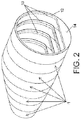
- the invention relates to a one-piece reinforced structure made of a composite material, preferably glass fibre or carbon fibre, that is manufactured without using moulds on which the composite material is deposited that must be subsequently removed from the finally obtained piece, since a portion of the very manufactured structure is used to perform the function of a mould during the manufacturing process.
- the one-piece reinforced structure made of finally obtained composite material is used for the manufacturing of the fuselage of an airplane, as shown in the example of figures 9 and 17 ; nevertheless, it can be used to manufacture another type of structure, such as for example one-piece structures for the wind energy, naval or automobile sectors (wind turbine blades, vehicle chassis, the hull of a ship, submarine, etc.).
- the figures show a base component (1,100) used in the manufacturing of the structure and which acts as a mould for the deposition of a coating (2) made of composite material, resulting in the base component (1,100) forming an indivisible portion of the finally obtained one-piece reinforced structure by means of the manufacturing process of the invention, with which the method does not require a specific mould to be used or removed after the curing process of the composite material.
- Figures 1 to 9 show a base component (1) according to an exemplary embodiment of the invention and figures 10 to 19 show another base component (100) according to another exemplary embodiment.
- the base component (1,100) comprises an outer contour (11,110) that is configured to receive the coating (2) made of composite material, said outer contour (11,110) defining the geometry of the finally obtained one-piece reinforced structure.
- the outer contour (11,110) has two open ends in each of which a flange (12,120) is located that projects transversely towards the inside of the base component (1,100), the flange (12,120) being intended to establish a joint with other base components (1,100).
- the outer contour (11,110) of the base component (1,100) has a cylindrical, conical or hollow prismatic geometry, according to the geometry of the one-piece structure to be manufactured.
- each flange (12,120) has a fold (13,130) that projects longitudinally towards the inside of the base component (1,100) according to a plane parallel to the outer contour (11,110), said fold (13,130) providing additional stiffness to the flange (12,120) of the base component (1,100).
- the flanges (12,120) additionally have a widened area (14,140) in the lower portion of the base component (1,100), which, if the structure is used as the fuselage of an aircraft, would correspond to the area wherein the floor of the aircraft is located.
- the base components (1,100) are made of glass fibre or carbon fibre, using unidirectional fibre that is applied in the optimal directions defined by the structural design of the base component (1,100).
- the base components (1,100) are made of dried fibre that subsequently requires the addition of resin for the curing thereof.
- the base components (1,100) are made of fibre preimpregneated with resin and therefore do not require a subsequent addition of resin.
- an assembly of base components (1,100) made of a partially cured composite material is used for the manufacturing of the one-piece reinforced structure of the invention.
- the partial curing enables the composite material of the base components (1,100) to acquire sufficient stiffness for the handling thereof in subsequent phases of the method, such that the very fibres made of composite material acquire sufficient stiffness so as to carry out the function of a mould whereon the coating (2) can be deposited, but it maintains the resin of the composite material applied in a "live" state, capable of creating a joint with a new layer of composite material with a minimal loss of mechanical properties in the interface between layers.
- base components (1,100) made of dried fibre that are impregnated with resin by means of an infusion process and that are heated by applying heat at a temperature lower than the curing temperature of the resin until a percentage of progress of the curing reaction comprised between 40% and 80% is reached in the composite material of the base components (1).
- base components (1,100) are used that are made of preimpregnated fibre that are heated by applying a temperature lower than the curing temperature of the resin until a percentage of progress of the curing reaction comprised between 40% and 80% is reached in the composite material of the base components (1,100).
- the base components (1,100) are partially cured and have acquired sufficient stiffness for the handling thereof they are joined together in order to define a surface whereon the coating (2) must be applied, corresponding to the geometry of the structure to be obtained.
- the base components (1,100) are joined together axially, the flanges (12,120) thereof facing each other.
- the joining is performed by using chemical means; nevertheless, mechanical means or a combination of chemical and mechanical means could be used to establish the joining.
- the base components (1,100) can have on the inside thereof, in the face opposite the outer contour (11,110), longitudinal sections (15,150) by way of stringers, as shown in figures 6 and 11 .
- the assembly of axially-joined base components (1,100) creates the surface whereon the coating (2) made of composite material is applied, such as glass fibre or carbon fibre.
- the coating (2) made of composite material is applied using automatic lay-up techniques.
- a lay-up head is used that applies strips or fibres made of composite material on the outer contour (11,110) of the base components (1,100) according to orientations defined to achieve a layering that meets the final requirements of the structure to be obtained.
- the coating (2) can be applied by using manual techniques without this altering the concept of the invention.
- the outer contour (11,110) of the joined base components (1,100) is covered with a fill material that enables a geometry to be obtained that is continuous and without cavities or recesses that hinder the subsequent process of applying the coating (2), or that can worsen the final properties of the finally obtained structure.
- This fill material preferably carbon-fibre based, acts as an additional coating of the joint of the base components (1,100) and, similarly to the coating (2), it has a structural function.
- the axially-joined base components (1,100) covered with the coating (2) are completely cured by applying heat such that the base components (1,100) and the coating (2) remain adhered together forming a single structure, wherein the removal of a mould is not necessary given that the base components (1) that performed said function form part of the structure obtained.
- the joining of the coating (2) and the outer contour (11,110) of the base components (1,100) corresponds to the skin of the fuselage
- the joining of the flanges (12,120) of two consecutive base components (1,100) corresponds to the frames of the fuselage.
- the fuselage created does not require rivets for the joining of different sections of fuselage, since the fuselage is not manufactured in sections but rather in a single piece, wherein the retention of the base components (1,100) is obtained by applying the coating (2) that surrounds them. Rivets are not even required for the joining of frames to the skin, since the base components (1,100) are adhered with the coating (2) in the curing process, all of which results in a fuselage with reduced weight.
- the joining of two base components (1,100) creates a geometry in the joining area thereof equivalent to that of a structural frame.
- the joining of the flanges (12,120) coming from each of the two base components (1,100) to be joined creates the equivalent of a web with a structural profile, while the folds (13,130) of each of the two base components (1,100) create a flange with a structural profile.
- an additional reinforcement is added to the joint on the inner portion thereof, on the surface created on the inside by the folds (13,130) of the base components (1,100), whereon a reinforcing ring (5) is added which offers greater consistency to the joints between base components (1,100) and reinforces the structural frame created in said joint.
- the base component (100) of the exemplary embodiment of the figures 10 to 19 has indentations (150) in the outer contour (110) thereof that act as structural reinforcement.
- the base component (100) of figures 10 to 19 and the method used for the manufacturing of the one-piece reinforced structures with said base component (100) is identical to the one described previously for the base component (1) of the exemplary embodiment of figures 1 to 9 with the special features indicated below.
- the indentations (150) define an alternating distribution of valleys and crests in the outer contour (110), which provides the base component (100) with increased strength.
- the valleys correspond to the indentations (150), which project towards the inside of the base component (100), and the crests correspond to the areas established between indentations (150), which project towards the outside of the base component (100) with respect to the valleys.
- the indentations (150) preferably have an undulating configuration and extend in the axial direction along all the entire width of the outer contour (110) of the base component (100), that is, the indentations (150) extend between the open ends of the outer contour (110), which enables the base component (100) to have an increased strength in the axial direction.
- this undulating configuration and the arrangement of the indentations (150) along all the entire width of the outer contour (110) is not limiting, the indentations (150) being able to have other shapes or extend in other directions different from the axial one, as well as not occupying the entire width of the outer contour (110), but rather portions of said width.
- the indentations (150) have a radius of curvature that is selected based on the structural requirements of the structure to be manufactured, a radius of curvature comprised between 50 and 500mm having preferably been selected.
- an assembly of base components (100) made of a partially cured composite material are used.
- the base components (100) are partially cured and have acquired sufficient stiffness for the handling thereof they are joined together in order to define a surface whereon the coating (2) must be applied, corresponding to the geometry of the structure to be obtained.
- the base components (100) are joined together axially, the flanges (120) thereof facing each other.
- the additional filling (3) that is applied in the indentations (150) is made of a material that has a lower density than the density of the composite material from which the base component (100) is manufactured, such that the weight of the base component (100) is optimised, which is a critical factor in the applications for which the invention is intended.
- the additional filling (3) can be a low-density foam or a similar material.
- the assembly of axially-joined base components (100) with the additional filling (3) in the indentations (150) creates the surface whereon the coating (2) made of composite material, such as glass fibre or carbon fibre, is applied.
- the filling material (4) preferably a series of sheets in unidirectional carbon fibre, which enables a geometry to be guaranteed that is continuous and without cavities or recesses that hinder the subsequent process of applying the additional filling (3) and of applying the coating (2), or that can worsen the final properties of the finally obtained structure.
- the preferably applied fill material (4) acts as a structural reinforcement for the joining of the base components (100).
- This fill material (4) is applied on the entire outer contour (110) of the base components (100), thereby covering the crests and the valleys, such that a continuity is obtained in the obtained structure.
- the fill material (4) can be applied partially, covering the outer contour (110) of the base components (100), thereby for example only being applied on the crests, or only on the valleys.
- the axially-joined base components (100) covered with the coating (2) are completely cured by applying heat such that the base components (100) and the coating (2) remain adhered together forming a single structure.
- the additional filling (3) is removed from the indentations (150), with which the weight of the one-piece structure obtained is optimised.
- the additional filling (3) can be made of a soluble material, such that the removal thereof is obtained by making a solvent circulate through the indentations (150).
- the removal of the additional filling (3), or the maintenance thereof in the indentations (150), depends on the weight requirements of the structure to be obtained and on the local warping behaviour thereof, as well as for example, the additional filling (3) can be maintained when a low-density foam or a similar material is used, since it does not compromise the weight of the structure.
- the coating (2) applied on the joined base components (100) also acts as structural reinforcement. Said coating (2) is applied on the outer contour (110) of the base components (100) coming into contact with the additional filling (3) of the indentations (150) and with the areas of the outer contour (110) established between indentations (150), that is, the crests of the outer contour (110). Thus, the cohesion of the base components (100) and the coating (2) is established by the crests.
- the cohesion of the base components (100) and the coating (2) is also established by the areas wherein the crests stay covered by the fill material (4).
- the indentations (150) of several base components (100) that are joined together axially perform the function of reinforcing stringers of the fuselage, such that it is not necessary to add said reinforcing stringers to the finally obtained structure in a subsequent process, with the resulting saving in time that this provides, apart from not requiring rivets to join the stringers to the structure, since the base components (100) carry the stringers intrinsically defined therein.
- the joining of two base components (100) creates a geometry in the joining area thereof equivalent to that of a structural frame.
- the joining of the flanges (120) coming from each of the two base components (100) to be joined creates the equivalent of a web with a structural profile
- the joining of the indentations (150) creates the equivalent of a structural stringer
- the folds (130) of each of the two base components (100) create a flange with a structural profile.
- bundles of fibres (6) are arranged at the ends of the indentations (150). Specifically, a bundle of fibres (6) is arranged in each transition between a valley and a crest of the outer contour (110) of a base component (100).
- the bundles of fibre (6) or "rovings” act as an additional reinforcement and prevent fissures in the transition between valleys and crests that are critical points of stress concentrations, finally being integrated in the one-piece structure resulting from the manufacturing process. It has been envisaged that the bundles of fibre (6) or "rovings” are carbon fibre with the fibres oriented in certain directions.
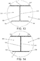
- Figure 16 shows a cross-sectional view of a non-limiting preferred embodiment of the one-piece reinforced structure obtained according to the method of the invention.
- Said cross section shows a base component (100), the outer contour (110) thereof having the fill material (4) deposited thereon, subsequently having applied the bundles of fibre (6) and the additional filling (3) in the indentations (150), and the coating (2) subsequently being applied.
- Figure 18 shows a base component (100) that makes up part of a one-piece reinforced structure for an amphibious version of a fuselage, while figure 19 shows the amphibious version of the fuselage.
Landscapes
- Engineering & Computer Science (AREA)
- Mechanical Engineering (AREA)
- Aviation & Aerospace Engineering (AREA)
- Chemical & Material Sciences (AREA)
- Composite Materials (AREA)
- Moulding By Coating Moulds (AREA)
Applications Claiming Priority (3)
| Application Number | Priority Date | Filing Date | Title |
|---|---|---|---|
| ES201631603A ES2676075B1 (es) | 2016-12-16 | 2016-12-16 | Procedimiento de fabricacion de estructuras reforzadas monocasco y estructura obtenida |
| ES201730921A ES2699721B2 (es) | 2017-07-11 | 2017-07-11 | Procedimiento de fabricacion de estructuras reforzadas monocasco y estructura obtenida |
| PCT/ES2017/070820 WO2018109255A1 (fr) | 2016-12-16 | 2017-12-15 | Processus de fabrication de structures renforcées monocoques et structure obtenue |
Publications (2)
| Publication Number | Publication Date |
|---|---|
| EP3556650A1 true EP3556650A1 (fr) | 2019-10-23 |
| EP3556650A4 EP3556650A4 (fr) | 2020-08-19 |
Family
ID=62558079
Family Applications (1)
| Application Number | Title | Priority Date | Filing Date |
|---|---|---|---|
| EP17881077.6A Pending EP3556650A4 (fr) | 2016-12-16 | 2017-12-15 | Processus de fabrication de structures renforcées monocoques et structure obtenue |
Country Status (3)
| Country | Link |
|---|---|
| US (1) | US11479333B2 (fr) |
| EP (1) | EP3556650A4 (fr) |
| WO (1) | WO2018109255A1 (fr) |
Cited By (2)
| Publication number | Priority date | Publication date | Assignee | Title |
|---|---|---|---|---|
| EP4119446A1 (fr) * | 2021-07-15 | 2023-01-18 | Airbus Operations, S.L.U. | Procédé d'assemblage de trames dans une coque d'aéronef |
| IT202200017862A1 (it) | 2022-08-31 | 2024-03-02 | A R S Tech S R L | Sistema per la produzione di elementi in fibra di carbonio senza giunzioni e metodo di funzionamento |
Families Citing this family (1)
| Publication number | Priority date | Publication date | Assignee | Title |
|---|---|---|---|---|
| EP3763619B1 (fr) | 2019-07-12 | 2023-08-09 | Muelles Y Ballestas Hispano-Alemanas Projects, S.L. | Élément structural de renforcement interne pour un fuselage et procédure de fabrication dudit élément structural |
Family Cites Families (31)
| Publication number | Priority date | Publication date | Assignee | Title |
|---|---|---|---|---|
| US3300355A (en) * | 1963-06-20 | 1967-01-24 | William E Adams | Method of making irregularly shaped hollow plastic bodies |
| US3978256A (en) * | 1974-06-14 | 1976-08-31 | The Boeing Company | Three-dimensional monocoque open-ended annular structure |
| US4086378A (en) * | 1975-02-20 | 1978-04-25 | Mcdonnell Douglas Corporation | Stiffened composite structural member and method of fabrication |
| WO1984000351A1 (fr) * | 1982-07-19 | 1984-02-02 | Boeing Co | Procede et appareil de lamination de fibres |
| JP2935722B2 (ja) * | 1990-02-28 | 1999-08-16 | 富士重工業株式会社 | 航空機の胴体構造およびその成形方法 |
| US5223067A (en) * | 1990-02-28 | 1993-06-29 | Fuji Jukogyo Kabushiki Kaisha | Method of fabricating aircraft fuselage structure |
| US6458309B1 (en) * | 1998-06-01 | 2002-10-01 | Rohr, Inc. | Method for fabricating an advanced composite aerostructure article having an integral co-cured fly away hollow mandrel |
| US6849150B1 (en) * | 2001-01-16 | 2005-02-01 | Lockheed Martin Corporation | System and method of forming structural assemblies with 3-D woven joint pre-forms |
| DE04714198T8 (de) * | 2003-02-24 | 2007-06-06 | Bell Helicopter Textron, Inc., Fort Worth | Kontaktversteifer für konstruktionshaut |
| US7018398B2 (en) | 2003-03-18 | 2006-03-28 | Elmedical Ltd. | System and method for treating urinary tract disorders |
| US7527222B2 (en) | 2004-04-06 | 2009-05-05 | The Boeing Company | Composite barrel sections for aircraft fuselages and other structures, and methods and systems for manufacturing such barrel sections |
| US7293737B2 (en) * | 2004-04-20 | 2007-11-13 | The Boeing Company | Co-cured stringers and associated mandrel and fabrication method |
| US7503368B2 (en) * | 2004-11-24 | 2009-03-17 | The Boeing Company | Composite sections for aircraft fuselages and other structures, and methods and systems for manufacturing such sections |
| US7410352B2 (en) * | 2005-04-13 | 2008-08-12 | The Boeing Company | Multi-ring system for fuselage barrel formation |
| DE102005026010B4 (de) | 2005-06-07 | 2010-12-30 | Airbus Deutschland Gmbh | Verfahren zur Herstellung einer verstärkten Schale zur Bildung von Teilkomponenten für Luftfahrzeuge |
| US7459048B2 (en) * | 2006-01-31 | 2008-12-02 | The Boeing Company | One-piece inner shell for full barrel composite fuselage |
| DE102006044683A1 (de) | 2006-02-07 | 2007-08-23 | Grob, Margret | Flugzeugkörper und Verfahren zu seiner Herstellung |
| CA2659371C (fr) * | 2006-07-28 | 2014-08-26 | Airbus Espana, S.L. | Procede de fabrication de pieces fabriquees au moyen de materiaux composites a deux cycles de durcissement |
| EP2128017B1 (fr) * | 2007-01-30 | 2013-07-24 | Airbus Operations S.L. | Structure de matiere composee pour le fuselage d'un aeronef et son procede de fabrication |
| US8043554B2 (en) * | 2007-06-08 | 2011-10-25 | The Boeing Company | Manufacturing process using bladderless mold line conformal hat stringer |
| EP2284076A1 (fr) * | 2009-08-12 | 2011-02-16 | Dermond-Forstner & Sreboth OG | Procédé de fabrication d'un corps creux développé sous forme de structure en sandwich |
| JP5576651B2 (ja) | 2009-12-25 | 2014-08-20 | 川崎重工業株式会社 | 複合材料構造物製造用マンドレルの組立方法およびマンドレルの組立装置 |
| US8765042B2 (en) * | 2010-06-11 | 2014-07-01 | Airbus Operations Gmbh | Fuselage section of an aircraft and method for the production of the fuselage section |
| US9051062B1 (en) * | 2012-02-08 | 2015-06-09 | Textron Innovations, Inc. | Assembly using skeleton structure |
| ITTO20120317A1 (it) | 2012-04-12 | 2013-10-13 | Alenia Aermacchi Spa | Procedimento per la fabbricazione di barili integrali di fusoliera in materiale composito |
| US8789837B2 (en) * | 2012-09-18 | 2014-07-29 | The Boeing Company | Transport and assembly system and method for composite barrel segments |
| US8985512B1 (en) * | 2012-09-21 | 2015-03-24 | The Boeing Company | Aircraft, fuselages, and associated methods |
| US9278748B2 (en) * | 2012-12-28 | 2016-03-08 | Embraer S.A. | Processes to fabricate composite tubular-reinforced panels integrating skin and stringers and the panels thereby fabricated |
| US9221236B1 (en) * | 2013-01-02 | 2015-12-29 | The Boeing Company | Systems and methods for assembling stiffened composite structures |
| DE102014109362B4 (de) * | 2014-07-04 | 2016-03-03 | Airbus Operation GmbH | Luftfahrzeugstrukturkomponente |
| US10046525B2 (en) * | 2016-09-30 | 2018-08-14 | The Boeing Company | Advanced variable radius laminated composite radius filler |
-
2017
- 2017-12-15 WO PCT/ES2017/070820 patent/WO2018109255A1/fr unknown
- 2017-12-15 EP EP17881077.6A patent/EP3556650A4/fr active Pending
- 2017-12-15 US US16/469,357 patent/US11479333B2/en active Active
Cited By (4)
| Publication number | Priority date | Publication date | Assignee | Title |
|---|---|---|---|---|
| EP4119446A1 (fr) * | 2021-07-15 | 2023-01-18 | Airbus Operations, S.L.U. | Procédé d'assemblage de trames dans une coque d'aéronef |
| US12054292B2 (en) | 2021-07-15 | 2024-08-06 | Airbus Operations S.L. | Method for the assembly of frames in an aircraft shell |
| IT202200017862A1 (it) | 2022-08-31 | 2024-03-02 | A R S Tech S R L | Sistema per la produzione di elementi in fibra di carbonio senza giunzioni e metodo di funzionamento |
| WO2024047428A1 (fr) | 2022-08-31 | 2024-03-07 | A.R.S. Tech S.R.L. | Système de production d'éléments de fibre de carbone sans jonction et procédé de fonctionnement |
Also Published As
| Publication number | Publication date |
|---|---|
| WO2018109255A1 (fr) | 2018-06-21 |
| US20200017186A1 (en) | 2020-01-16 |
| EP3556650A4 (fr) | 2020-08-19 |
| US11479333B2 (en) | 2022-10-25 |
Similar Documents
| Publication | Publication Date | Title |
|---|---|---|
| US10737760B2 (en) | Multi-box wing spar and skin | |
| US6190484B1 (en) | Monolithic composite wing manufacturing process | |
| EP3002117B1 (fr) | Structure composite ayant des têtes de clou à surface réduite et procédé de fabricaton de celle-ci | |
| US11479333B2 (en) | Method for manufacturing a one-piece reinforced structure and obtained structure | |
| EP2814731B1 (fr) | Structures composites renforcées pour avions et leurs procédés de fabrication | |
| US8444090B2 (en) | Transverse butt connection between two fuselage sections | |
| EP2301840A2 (fr) | Structure d'aeronef integré de matériau composite | |
| US20080277531A1 (en) | Hybrid Composite Panel Systems and Methods | |
| KR20130143690A (ko) | 복합재 햇 보강재, 복합재 햇-보강 압력 웨브, 및 그 제조 방법 | |
| EP2857186A2 (fr) | Procédé de fabrication d'un composant de composite fibreux, composant de composite fibreux et élément structurel pour un avion ou un engin spatial | |
| US9144949B2 (en) | Molding tool and method for manufacturing a fiber reinforced plastic aerodynamic aircraft component | |
| EP2676877B1 (fr) | Panneaux structuraux composites et fuselages d'avion | |
| US10005267B1 (en) | Formation of complex composite structures using laminate templates | |
| US20130264422A1 (en) | Aircraft frame and method for obtaining the same | |
| US20150251400A1 (en) | Integrated lamination process for manufacturing a shell element | |
| US20110206875A1 (en) | Method and arrangement for production of an integral hollow-profiled component with fibre composite material | |
| EP2727820A1 (fr) | Lisse | |
| EP2730397B1 (fr) | Procédé de production d'un élément de coque composite | |
| EP2746038B1 (fr) | Procédé de fabrication d'un composant structurel, composant structurel, coque, et aéronef ou engin spatial | |
| US20100230538A1 (en) | Closed structure of composite material | |
| ES2699721B2 (es) | Procedimiento de fabricacion de estructuras reforzadas monocasco y estructura obtenida | |
| ES2676075B1 (es) | Procedimiento de fabricacion de estructuras reforzadas monocasco y estructura obtenida |
Legal Events
| Date | Code | Title | Description |
|---|---|---|---|
| STAA | Information on the status of an ep patent application or granted ep patent |
Free format text: STATUS: THE INTERNATIONAL PUBLICATION HAS BEEN MADE |
|
| PUAI | Public reference made under article 153(3) epc to a published international application that has entered the european phase |
Free format text: ORIGINAL CODE: 0009012 |
|
| STAA | Information on the status of an ep patent application or granted ep patent |
Free format text: STATUS: REQUEST FOR EXAMINATION WAS MADE |
|
| 17P | Request for examination filed |
Effective date: 20190716 |
|
| AK | Designated contracting states |
Kind code of ref document: A1 Designated state(s): AL AT BE BG CH CY CZ DE DK EE ES FI FR GB GR HR HU IE IS IT LI LT LU LV MC MK MT NL NO PL PT RO RS SE SI SK SM TR |
|
| AX | Request for extension of the european patent |
Extension state: BA ME |
|
| DAV | Request for validation of the european patent (deleted) | ||
| DAX | Request for extension of the european patent (deleted) | ||
| A4 | Supplementary search report drawn up and despatched |
Effective date: 20200721 |
|
| RIC1 | Information provided on ipc code assigned before grant |
Ipc: B29C 70/30 20060101ALI20200715BHEP Ipc: B64C 1/00 20060101AFI20200715BHEP Ipc: B64C 1/06 20060101ALI20200715BHEP |
|
| STAA | Information on the status of an ep patent application or granted ep patent |
Free format text: STATUS: EXAMINATION IS IN PROGRESS |
|
| 17Q | First examination report despatched |
Effective date: 20220210 |
|
| P01 | Opt-out of the competence of the unified patent court (upc) registered |
Effective date: 20230529 |