EP3556645B1 - Cycle crank assembly - Google Patents
Cycle crank assembly Download PDFInfo
- Publication number
- EP3556645B1 EP3556645B1 EP19169750.7A EP19169750A EP3556645B1 EP 3556645 B1 EP3556645 B1 EP 3556645B1 EP 19169750 A EP19169750 A EP 19169750A EP 3556645 B1 EP3556645 B1 EP 3556645B1
- Authority
- EP
- European Patent Office
- Prior art keywords
- crank
- cycle
- spindle
- pedal
- deformable member
- Prior art date
- Legal status (The legal status is an assumption and is not a legal conclusion. Google has not performed a legal analysis and makes no representation as to the accuracy of the status listed.)
- Active
Links
- 239000002131 composite material Substances 0.000 claims description 4
- 241000239290 Araneae Species 0.000 claims description 3
- 239000011152 fibreglass Substances 0.000 claims description 3
- 230000001681 protective effect Effects 0.000 claims description 2
- 238000012549 training Methods 0.000 description 5
- 230000033001 locomotion Effects 0.000 description 4
- 238000000429 assembly Methods 0.000 description 3
- 230000000712 assembly Effects 0.000 description 3
- 238000004146 energy storage Methods 0.000 description 3
- 239000000463 material Substances 0.000 description 3
- 229910052751 metal Inorganic materials 0.000 description 3
- 239000002184 metal Substances 0.000 description 3
- 229920000049 Carbon (fiber) Polymers 0.000 description 2
- 239000004917 carbon fiber Substances 0.000 description 2
- 230000007423 decrease Effects 0.000 description 2
- VNWKTOKETHGBQD-UHFFFAOYSA-N methane Chemical compound C VNWKTOKETHGBQD-UHFFFAOYSA-N 0.000 description 2
- 230000035939 shock Effects 0.000 description 2
- 238000012360 testing method Methods 0.000 description 2
- 238000012546 transfer Methods 0.000 description 2
- 229910000831 Steel Inorganic materials 0.000 description 1
- 238000010521 absorption reaction Methods 0.000 description 1
- 229910052782 aluminium Inorganic materials 0.000 description 1
- XAGFODPZIPBFFR-UHFFFAOYSA-N aluminium Chemical compound [Al] XAGFODPZIPBFFR-UHFFFAOYSA-N 0.000 description 1
- 238000013459 approach Methods 0.000 description 1
- 230000009286 beneficial effect Effects 0.000 description 1
- 230000005540 biological transmission Effects 0.000 description 1
- 230000001351 cycling effect Effects 0.000 description 1
- 238000013461 design Methods 0.000 description 1
- 238000002474 experimental method Methods 0.000 description 1
- 238000009434 installation Methods 0.000 description 1
- 239000000203 mixture Substances 0.000 description 1
- 239000004033 plastic Substances 0.000 description 1
- 229920003023 plastic Polymers 0.000 description 1
- 230000000087 stabilizing effect Effects 0.000 description 1
- 239000010959 steel Substances 0.000 description 1
Images


Classifications
-
- B—PERFORMING OPERATIONS; TRANSPORTING
- B62—LAND VEHICLES FOR TRAVELLING OTHERWISE THAN ON RAILS
- B62M—RIDER PROPULSION OF WHEELED VEHICLES OR SLEDGES; POWERED PROPULSION OF SLEDGES OR SINGLE-TRACK CYCLES; TRANSMISSIONS SPECIALLY ADAPTED FOR SUCH VEHICLES
- B62M3/00—Construction of cranks operated by hand or foot
-
- B—PERFORMING OPERATIONS; TRANSPORTING
- B62—LAND VEHICLES FOR TRAVELLING OTHERWISE THAN ON RAILS
- B62M—RIDER PROPULSION OF WHEELED VEHICLES OR SLEDGES; POWERED PROPULSION OF SLEDGES OR SINGLE-TRACK CYCLES; TRANSMISSIONS SPECIALLY ADAPTED FOR SUCH VEHICLES
- B62M1/00—Rider propulsion of wheeled vehicles
- B62M1/10—Rider propulsion of wheeled vehicles involving devices which enable the mechanical storing and releasing of energy occasionally, e.g. arrangement of flywheels
- B62M1/105—Rider propulsion of wheeled vehicles involving devices which enable the mechanical storing and releasing of energy occasionally, e.g. arrangement of flywheels using elastic elements
-
- B—PERFORMING OPERATIONS; TRANSPORTING
- B62—LAND VEHICLES FOR TRAVELLING OTHERWISE THAN ON RAILS
- B62M—RIDER PROPULSION OF WHEELED VEHICLES OR SLEDGES; POWERED PROPULSION OF SLEDGES OR SINGLE-TRACK CYCLES; TRANSMISSIONS SPECIALLY ADAPTED FOR SUCH VEHICLES
- B62M3/00—Construction of cranks operated by hand or foot
- B62M3/003—Combination of crank axles and bearings housed in the bottom bracket
-
- B—PERFORMING OPERATIONS; TRANSPORTING
- B62—LAND VEHICLES FOR TRAVELLING OTHERWISE THAN ON RAILS
- B62K—CYCLES; CYCLE FRAMES; CYCLE STEERING DEVICES; RIDER-OPERATED TERMINAL CONTROLS SPECIALLY ADAPTED FOR CYCLES; CYCLE AXLE SUSPENSIONS; CYCLE SIDE-CARS, FORECARS, OR THE LIKE
- B62K2201/00—Springs used in cycle frames or parts thereof
- B62K2201/06—Leaf springs
-
- B—PERFORMING OPERATIONS; TRANSPORTING
- B62—LAND VEHICLES FOR TRAVELLING OTHERWISE THAN ON RAILS
- B62M—RIDER PROPULSION OF WHEELED VEHICLES OR SLEDGES; POWERED PROPULSION OF SLEDGES OR SINGLE-TRACK CYCLES; TRANSMISSIONS SPECIALLY ADAPTED FOR SUCH VEHICLES
- B62M1/00—Rider propulsion of wheeled vehicles
- B62M1/36—Rider propulsion of wheeled vehicles with rotary cranks, e.g. with pedal cranks
-
- B—PERFORMING OPERATIONS; TRANSPORTING
- B62—LAND VEHICLES FOR TRAVELLING OTHERWISE THAN ON RAILS
- B62M—RIDER PROPULSION OF WHEELED VEHICLES OR SLEDGES; POWERED PROPULSION OF SLEDGES OR SINGLE-TRACK CYCLES; TRANSMISSIONS SPECIALLY ADAPTED FOR SUCH VEHICLES
- B62M3/00—Construction of cranks operated by hand or foot
- B62M2003/006—Crank arrangements to overcome dead points
Definitions
- TW M 286 179 U discloses a cycle crank assembly with crank arms formed from carbon fiber composite material and having a core formed from metal.
- the core interlocks with a first joint member that is formed from metal.
- the first joint member has a toothed inner surface for securely fixing the crank arm on a crank spindle.
- the crank assembly is lightweight and has good force transmission and endurance properties. Further conventional crank arm assemblies are known from US 2015/007688 A1 , US 2015/175241 A1 and US 2004/211289 A1 .
- TW M 286 179 U discloses a cycle crank assembly in accordance with the preamble of claim 1.
- FIG. 1 schematically shows an example bicycle 100 including a drivetrain including a crank assembly 102.
- Crank assembly 102 includes two crank arms (e.g., right crank arm 104) with pedals (e.g., right pedal 106) affixed to the ends of the crank arms.
- the two crank arms are each attached to a crank spindle 108 and mounted 180 degrees apart.
- the crank spindle may be attached to a rear wheel drivetrain connector configured to translate motion of the crank arms into motion of the rear wheel of the cycle.
- spindle 108 is attached to a chainring 110.
- Spindle 108 may be attached to chainring 110 via a cycle spider (not shown) or another suitable connector.
- Chainring 110 rotates with spindle 108, and this rotation is applied to rear wheel 112 via a bicycle chain.
- movement of the crank spindle e.g., caused by application of force to the pedals
- crank assembly 102 may be used with any suitable rear wheel drivetrain connector.
- bicycle 100 uses a bicycle spider, chainring, and bicycle chain to transfer power to real wheel 112.
- other suitable rear wheel drivetrain connectors may be used - e.g., a belt sprocket for a belt-drive bicycle, or a bevel gear for a shaft-driven bicycle.
- FIG. 2 shows another view of a portion of cycle crank assembly 102.
- crank assembly 102 has been removed from bicycle 100, and pedal 106 and chainring 110 have been removed from the crank assembly.
- crank arm 104 includes a pedal interface 105 configured to accept a pedal spindle of pedal 106 shown in FIG. 1 .
- FIG. 2 more closely shows the attachment between crank arm 104 and crank spindle 108.
- crank spindle 108 will be positioned within a bottom bracket of bicycle 100 along with one or more bearings, thereby securing and stabilizing the crank spindle while allowing the crank spindle to freely rotate.
- crank arm is typically attached to a crank spindle.
- the attachment between the crank arm and the crank spindle is configured to prevent slipping of one relative to the other.
- the drivetrain is substantially rigid, such that power transfer from the crank arm to the rotating wheel is practically instantaneous and does not change along the components of the drivetrain.
- cycle crank assembly 102 incorporates a slip connection between the crank arm and crank spindle.
- the crank arm is able to rotate about the crank spindle.
- the crank arms can rotate more than the crank spindle throughout part of a pedal stroke, and the crank arms can rotate less than the crank spindle throughout another part of the pedal stroke.
- FIGS. 3A and 3B show other partial views of cycle crank assembly 102.
- FIG. 3A shows the crank assembly in an assembled state, while FIG. 3B shows an exploded view.
- crank arm 104 is shown as being partially transparent.
- crank assembly 102 further includes a resiliently deformable member 114 and a slip connection 116, visible in FIG. 3A through the transparent crank arm and in FIG. 3B as exploded components. While FIGS. 3A and 3B only show right crank arm 104 having a resiliently deformable member and slip connection, the left crank arm may include a resiliently deformable member and slip connection as well. Because resiliently deformable member 114 is attached to crank arm 104, rotation of the crank arm causes corresponding rotation of the resiliently deformable member, which is translated to crank spindle 108.
- crank arm 104 when a load is applied to the crank arm (e.g., during a pedal downstroke), some amount of deformation of resiliently deformable member 114 will occur.
- crank arm 104 in response to the load, crank arm 104 will rotate, and resiliently deformable member 114 will deform (i.e., bend), storing a portion of the energy transferred by the load.
- the crank arm will "slip" somewhat relative to crank spindle 108, meaning the crank arm will rotate about the crank spindle.
- the crank arm may rotate by as much as one to four degrees around the spindle under load.
- the amount of "slip" and corresponding amount of energy storage is proportional to the force applied to the pedal. Higher forces will cause relatively more slip and relatively more energy storage. As such, the maximum amount of slip and corresponding amount of energy storage will generally occur from the pedal downstroke when the pedal is at approximately 90 degrees and pedal forces 120 are highest in the direction of rotation (as shown in FIG. 4A ). As such, the pedal downstroke may cause the crank arm 104 to rotate more than the crank spindle 108, but at least some of the difference in rotation may be stored as spring energy in the resiliently deformable member 114. This stored spring energy may be returned when relative force in the direction of rotation (i.e., pedal force 120) on the pedal decreases.
- the minimum amount of force on the pedal in the direction of rotation will generally occur during the pedal dead stroke, when the pedal is at approximately 180 degrees (As shown in FIG. 4B ).
- the resiliently deformable member 114 may return to its original shape and stored energy from the resiliently deformable member 114 may be returned.
- the released energy causes the crank spindle 108 to rotate faster than the crank arm 104, and the released energy may be transferred to the rear wheel drivetrain connector.
- the resiliently deformable member smooths the cyclist's output by storing some energy from the cyclist's most powerful portions of a pedal stroke and returning the stored energy during the cyclist's least powerful portions of the pedal stroke.
- the cycle crank assembly disclosed herein can improve the efficiency with which power is transferred to a rotating wheel by at least 4%.
- the experimental configuration included a bicycle mounted to a computerized training stand. According to the design of the training stand, the rear wheel of the bicycle was removed, and the bicycle drivetrain was attached to a disc incorporated into the training stand, such that power provided to the drivetrain of the bicycle caused rotation of the disc. Sensors attached to the disc allowed power, as well as equivalent ground speed and distance, to be measured. The power and total energy provided by the cyclist to each pedal was also measured using pedal-based power meters.
- the experiment was conducted in eight 30-minute sessions, including four sessions with a conventional crank assembly as well as four sessions with the modified crank assembly described herein.
- the average speed target as measured at the training stand, was 19.3 km/h, at a 3% slope to prevent freewheeling and coasting during the test.
- the conventional crank assembly showed an average power of 197.2W and an average total energy expenditure of 355kJ, both measured at the pedals.
- the modified crank assembly described herein the average power was 187.8W and the average total energy expenditure was 337.75kJ.
- each crank assembly had the same average speed (19.3km/h), cadence (71rpm), and equivalent distance (9.66km), when averaged across the four sessions for each crank assembly.
- the modified crank assembly described herein achieved the same average speed and equivalent ground distance despite the cyclist providing overall less power and energy to the pedals, on average. This represents an approximately 4% increase in cycling efficiency as compared to a conventional crank assembly. It is thought that the improvement can be attributed to an overall smoother torque profile, as power supplied by the cyclist during the pedal down stroke was stored by the resiliently deformable member and released during the pedal dead stroke. Energy savings may also potentially arise through reduced flexing of the bicycle frame and other components.
- resiliently deformable member 114 is shown disposed within a hollow of crank arm 104.
- the hollow will, according to the invention, be larger in size than the resiliently deformable member along at least part of the length of the hollow so as to permit deformation of the resiliently deformable member while under load.
- the hollow may have any suitable size and shape.
- the hollow may narrow to have substantially the same size and shape as the resiliently deformable member proximate to pedal interface 105, such that the resiliently deformable member is snugly secured within the hollow.
- the hollow may additionally or alternatively include clips, brackets, magnets, and/or other fasteners configured to secure the resiliently deformable member in place.
- FIG. 3A shows a member holder 118 configured to secure the pedal-distal end of resiliently deformable member 114 within a hollow of crank spindle 108.
- slip connection 116 and crank spindle 108 each incorporate cutouts sized and shaped to accommodate the resiliently deformable member.
- the crank arm may have a window that aligns with the cutouts.
- the resiliently deformable member may be installed by sliding the pedal-proximate end of the resiliently-deformable member through the window, the slip connection cutout, and the crank spindle cutout until the pedal-proximate end of the resiliently deformable member is securely seated proximate to the pedal interface.
- the pedal-distal end of the resiliently-deformable member will be within the hollow of crank spindle 108, as shown in FIG. 3A .
- a protective cover or cap may optionally be installed to cover and protect the pedal-distal end of the resiliently-deformable member post-installation.
- the resiliently-deformable member may be installed and secured in any suitable way.
- the resiliently deformable member need not be positioned within the crank arm and may instead be external to the crank arm.
- the resiliently deformable member may have any suitable size and shape.
- the resiliently deformable member may be implemented as a leaf spring, with any suitable spring constant.
- the leaf spring may have a thickness of, for example, between 6 and 10 mm.
- the leaf spring may have a spring constant such that a load of 100 lbs. causes a deformation of between 0.1 and 0.5 inches, while a load of 200 lbs. causes a deformation of between 0.2 and 1.0 inches.
- the resiliently deformable member may have another suitable spring constant, structure, and/or composition.
- a preferred material for the leaf spring is fiberglass composite.
- crank arm 104 crank spindle 108, resiliently deformable member 114, etc.
- crank arm 104 crank spindle 108, resiliently deformable member 114, etc.
- metal e.g., steel or aluminum
- the components of cycle crank assembly 102 may be constructed from multiple materials, depending on what is optimal or desirable for each individual component.
- slip connection 116 permits rotation of crank arm 104 about crank spindle 108.
- Slip connection 116 includes a sleeve bearing.
- slip connection 116 includes a sleeve bearing having two cutouts for resiliently deformable member 114 to pass through.
- Crank spindle 108 has similar cutouts, allowing resiliently deformable member 114 to pass through the hollow of the crank spindle as described above, where it is held in place by a member holder 118.
- the slip connection may take another suitable form, provided it permits rotation of the crank arm about the crank spindle.
- the shapes and arrangement of components shown in FIGS. 3A and 3B are presented as an example, and numerous changes may be made.
- Crank assembly 102 may provide numerous advantages in addition to improving pedaling efficiency.
- the maximum torque applied by the cyclist to the crank arms is reduced by the resiliently deformable members and not instantaneously transferred to the rotating wheel. This reduces the risk that the rotating wheel will slip, especially on a wet road surface.
- the resiliently deformable members may serve to absorb shocks to the cycle (e.g., when riding over a rough road surface), which can result in a smoother ride for the cyclist. Absorption of force by the resiliently deformable member can also reduce stresses and shocks to the cycle frame itself.
Description
- This application claims priority to
U.S. Non-Provisional Patent Application Serial Number 16/367,784, filed March 28, 2019 U.S. Provisional Patent Application Serial Number 62/659,070, filed April 17, 2018 -
TW M 286 179 U US 2015/007688 A1 ,US 2015/175241 A1 andUS 2004/211289 A1 . - The document
TW M 286 179 U -
-
FIG. 1 schematically shows an example bicycle. -
FIG. 2 shows portions of an example cycle crank assembly. -
FIGS. 3A and3B show portions of another example cycle crank assembly. -
FIGS. 4A and 4B schematically illustrate deformation of a resiliently deformable member of a cycle crank assembly. - Human-powered cycles, such as bicycles, unicycles, tricycles, etc., typically incorporate a drivetrain configured to translate motion of a crank arm into rotation of a wheel.
FIG. 1 schematically shows anexample bicycle 100 including a drivetrain including acrank assembly 102.Crank assembly 102 includes two crank arms (e.g., right crank arm 104) with pedals (e.g., right pedal 106) affixed to the ends of the crank arms. The two crank arms are each attached to acrank spindle 108 and mounted 180 degrees apart. - The crank spindle may be attached to a rear wheel drivetrain connector configured to translate motion of the crank arms into motion of the rear wheel of the cycle. In the case of
bicycle 100,spindle 108 is attached to achainring 110. Spindle 108 may be attached to chainring 110 via a cycle spider (not shown) or another suitable connector. Chainring 110 rotates withspindle 108, and this rotation is applied torear wheel 112 via a bicycle chain. Thus, movement of the crank spindle (e.g., caused by application of force to the pedals) causes rotation of the rear wheel of the bicycle, which causes the bicycle to move. - The cycle crank assembly discussed herein will primarily be described with respect to bicycles - i.e., human-powered cycles having two wheels. However, similar crank assemblies may be incorporated into cycles having any suitable number of wheels.
Crank assembly 102 may be used with any suitable rear wheel drivetrain connector. For example,bicycle 100 uses a bicycle spider, chainring, and bicycle chain to transfer power toreal wheel 112. In other examples, other suitable rear wheel drivetrain connectors may be used - e.g., a belt sprocket for a belt-drive bicycle, or a bevel gear for a shaft-driven bicycle. -
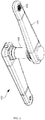
FIG. 2 shows another view of a portion ofcycle crank assembly 102. In this view,crank assembly 102 has been removed frombicycle 100, andpedal 106 andchainring 110 have been removed from the crank assembly. As shown,crank arm 104 includes apedal interface 105 configured to accept a pedal spindle ofpedal 106 shown inFIG. 1 . Furthermore,FIG. 2 more closely shows the attachment betweencrank arm 104 andcrank spindle 108. Typically,crank spindle 108 will be positioned within a bottom bracket ofbicycle 100 along with one or more bearings, thereby securing and stabilizing the crank spindle while allowing the crank spindle to freely rotate. - There are a variety of ways in which a crank arm is typically attached to a crank spindle. In more conventional bicycle drivetrains, the attachment between the crank arm and the crank spindle is configured to prevent slipping of one relative to the other. In other words, it is not generally possible to rotate a crank arm without causing an equal rotation of the crank spindle attached to the crank arm. Rather, the drivetrain is substantially rigid, such that power transfer from the crank arm to the rotating wheel is practically instantaneous and does not change along the components of the drivetrain.
- In contrast,
cycle crank assembly 102 incorporates a slip connection between the crank arm and crank spindle. Unlike conventional crank assemblies, the crank arm is able to rotate about the crank spindle. In other words, the crank arms can rotate more than the crank spindle throughout part of a pedal stroke, and the crank arms can rotate less than the crank spindle throughout another part of the pedal stroke. -
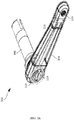
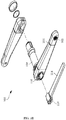
FIGS. 3A and3B show other partial views ofcycle crank assembly 102.FIG. 3A shows the crank assembly in an assembled state, whileFIG. 3B shows an exploded view. Furthermore, inFIG. 3A ,crank arm 104 is shown as being partially transparent. - As shown in
FIGS. 3A and3B ,crank assembly 102 further includes a resilientlydeformable member 114 and aslip connection 116, visible inFIG. 3A through the transparent crank arm and inFIG. 3B as exploded components. WhileFIGS. 3A and3B only showright crank arm 104 having a resiliently deformable member and slip connection, the left crank arm may include a resiliently deformable member and slip connection as well. Because resilientlydeformable member 114 is attached tocrank arm 104, rotation of the crank arm causes corresponding rotation of the resiliently deformable member, which is translated tocrank spindle 108. However, when a load is applied to the crank arm (e.g., during a pedal downstroke), some amount of deformation of resilientlydeformable member 114 will occur. Thus, in response to the load,crank arm 104 will rotate, and resilientlydeformable member 114 will deform (i.e., bend), storing a portion of the energy transferred by the load. At this time, the crank arm will "slip" somewhat relative tocrank spindle 108, meaning the crank arm will rotate about the crank spindle. In one example, the crank arm may rotate by as much as one to four degrees around the spindle under load. - The amount of "slip" and corresponding amount of energy storage is proportional to the force applied to the pedal. Higher forces will cause relatively more slip and relatively more energy storage. As such, the maximum amount of slip and corresponding amount of energy storage will generally occur from the pedal downstroke when the pedal is at approximately 90 degrees and
pedal forces 120 are highest in the direction of rotation (as shown inFIG. 4A ). As such, the pedal downstroke may cause thecrank arm 104 to rotate more than thecrank spindle 108, but at least some of the difference in rotation may be stored as spring energy in the resilientlydeformable member 114. This stored spring energy may be returned when relative force in the direction of rotation (i.e., pedal force 120) on the pedal decreases. - The minimum amount of force on the pedal in the direction of rotation will generally occur during the pedal dead stroke, when the pedal is at approximately 180 degrees (As shown in
FIG. 4B ). As such, as relative pedal force and effective torque decreases during the pedal dead stroke, the resilientlydeformable member 114 may return to its original shape and stored energy from the resilientlydeformable member 114 may be returned. The released energy causes thecrank spindle 108 to rotate faster than thecrank arm 104, and the released energy may be transferred to the rear wheel drivetrain connector. In essence, the resiliently deformable member smooths the cyclist's output by storing some energy from the cyclist's most powerful portions of a pedal stroke and returning the stored energy during the cyclist's least powerful portions of the pedal stroke. - Based on preliminary testing, it is thought that the cycle crank assembly disclosed herein can improve the efficiency with which power is transferred to a rotating wheel by at least 4%. The experimental configuration included a bicycle mounted to a computerized training stand. According to the design of the training stand, the rear wheel of the bicycle was removed, and the bicycle drivetrain was attached to a disc incorporated into the training stand, such that power provided to the drivetrain of the bicycle caused rotation of the disc. Sensors attached to the disc allowed power, as well as equivalent ground speed and distance, to be measured. The power and total energy provided by the cyclist to each pedal was also measured using pedal-based power meters.
- The experiment was conducted in eight 30-minute sessions, including four sessions with a conventional crank assembly as well as four sessions with the modified crank assembly described herein. The average speed target, as measured at the training stand, was 19.3 km/h, at a 3% slope to prevent freewheeling and coasting during the test. When the results for each set of four sessions were averaged, the conventional crank assembly showed an average power of 197.2W and an average total energy expenditure of 355kJ, both measured at the pedals. For the modified crank assembly described herein, the average power was 187.8W and the average total energy expenditure was 337.75kJ. Despite the different power and energy readings, and as measured at the training stand, each crank assembly had the same average speed (19.3km/h), cadence (71rpm), and equivalent distance (9.66km), when averaged across the four sessions for each crank assembly.
- In other words, the modified crank assembly described herein achieved the same average speed and equivalent ground distance despite the cyclist providing overall less power and energy to the pedals, on average. This represents an approximately 4% increase in cycling efficiency as compared to a conventional crank assembly. It is thought that the improvement can be attributed to an overall smoother torque profile, as power supplied by the cyclist during the pedal down stroke was stored by the resiliently deformable member and released during the pedal dead stroke. Energy savings may also potentially arise through reduced flexing of the bicycle frame and other components.
- Additional details regarding an example configuration of the cycle crank assembly will now be described with respect to
FIG. 3A . InFIG. 3A , resilientlydeformable member 114 is shown disposed within a hollow ofcrank arm 104. The hollow will, according to the invention, be larger in size than the resiliently deformable member along at least part of the length of the hollow so as to permit deformation of the resiliently deformable member while under load. However, the hollow may have any suitable size and shape. In some examples, the hollow may narrow to have substantially the same size and shape as the resiliently deformable member proximate topedal interface 105, such that the resiliently deformable member is snugly secured within the hollow. The hollow may additionally or alternatively include clips, brackets, magnets, and/or other fasteners configured to secure the resiliently deformable member in place. For example,FIG. 3A shows amember holder 118 configured to secure the pedal-distal end of resilientlydeformable member 114 within a hollow ofcrank spindle 108. - As shown in
FIG. 3A ,slip connection 116 and crankspindle 108 each incorporate cutouts sized and shaped to accommodate the resiliently deformable member. Furthermore, the crank arm may have a window that aligns with the cutouts. Accordingly, the resiliently deformable member may be installed by sliding the pedal-proximate end of the resiliently-deformable member through the window, the slip connection cutout, and the crank spindle cutout until the pedal-proximate end of the resiliently deformable member is securely seated proximate to the pedal interface. At this point, the pedal-distal end of the resiliently-deformable member will be within the hollow ofcrank spindle 108, as shown inFIG. 3A . A protective cover or cap may optionally be installed to cover and protect the pedal-distal end of the resiliently-deformable member post-installation. - In other examples, the resiliently-deformable member may be installed and secured in any suitable way. Furthermore, the resiliently deformable member need not be positioned within the crank arm and may instead be external to the crank arm.
- The resiliently deformable member may have any suitable size and shape. In some examples, the resiliently deformable member may be implemented as a leaf spring, with any suitable spring constant. The leaf spring may have a thickness of, for example, between 6 and 10 mm. The leaf spring may have a spring constant such that a load of 100 lbs. causes a deformation of between 0.1 and 0.5 inches, while a load of 200 lbs. causes a deformation of between 0.2 and 1.0 inches. In other examples, the resiliently deformable member may have another suitable spring constant, structure, and/or composition. A preferred material for the leaf spring is fiberglass composite.
- Components of
crank assembly 102 may be made from any suitable materials. In some examples, crankarm 104, crankspindle 108, resilientlydeformable member 114, etc., may be made from some variety of metal (e.g., steel or aluminum). In other examples, it may be beneficial for these components to be constructed from relatively light-weight components, such as high-durability plastics, carbon fiber, fiberglass composites, etc. Furthermore, the components of cycle crankassembly 102 may be constructed from multiple materials, depending on what is optimal or desirable for each individual component. - As discussed above,
slip connection 116 permits rotation ofcrank arm 104 about crankspindle 108.Slip connection 116, according to the invention, includes a sleeve bearing. In the example ofFIGS. 3A and3B ,slip connection 116 includes a sleeve bearing having two cutouts for resilientlydeformable member 114 to pass through. Crankspindle 108 has similar cutouts, allowing resilientlydeformable member 114 to pass through the hollow of the crank spindle as described above, where it is held in place by amember holder 118. However, in other examples, the slip connection may take another suitable form, provided it permits rotation of the crank arm about the crank spindle. In general, the shapes and arrangement of components shown inFIGS. 3A and3B are presented as an example, and numerous changes may be made. - Crank
assembly 102 may provide numerous advantages in addition to improving pedaling efficiency. In one example, when a cyclist is accelerating after turning a corner, the maximum torque applied by the cyclist to the crank arms is reduced by the resiliently deformable members and not instantaneously transferred to the rotating wheel. This reduces the risk that the rotating wheel will slip, especially on a wet road surface. Furthermore, the resiliently deformable members may serve to absorb shocks to the cycle (e.g., when riding over a rough road surface), which can result in a smoother ride for the cyclist. Absorption of force by the resiliently deformable member can also reduce stresses and shocks to the cycle frame itself. - It will be understood that the configurations and/or approaches described herein are exemplary in nature, and that these specific embodiments or examples are not to be considered in a limiting sense, because numerous variations are possible.
- The scope of the present invention is defined by the appended claims.
Claims (13)
- A cycle crank assembly (102), comprising:a crank spindle (108);a drivetrain connector configured to translate rotation of the crank spindle (108) into rotation of a wheel (112);a crank arm (104) including a pedal interface (105) configured to receive a pedal spindle of a cycle pedal (106);the cycle crank assembly further comprises:
a resiliently deformable member (114) connected to the crank spindle (108) and to the crank arm (104) proximate to the pedal interface (105), wherein the resiliently deformable member (114) translates rotation of the crank arm (104) into rotation of the crank spindle (108), and wherein the resiliently deformable member (114) deforms under load to store pedal energy provided by a rider to the cycle pedal (106), and returns at least a portion of the pedal energy when not under load in a direction of the rotation, and characterised in that the cycle crank assembly, comprises a slip connection (116) configured to allow the crank arm (114) to rotate about the crank spindle,and the slip connection (116) including a sleeve bearing;
and the resiliently deformable member (114) is disposed within a hollow defined within the crank arm (104), wherein the hollow defined within the crank arm (104) is larger in size than the resiliently deformable member (114) along at least a portion of a length of the hollow so as to permit deformation of the resiliently deformable member (114) when under load. - The cycle crank assembly of claim 1, wherein the hollow defined within the crank arm (104) narrows to have substantially a same size and shape as the resiliently deformable member (114) proximate to the pedal interface (105) of the crank arm (104).
- The cycle crank assembly of one of claims 1 or 2, wherein the crank arm (104) includes one or more internal fasteners configured to secure the resiliently deformable member (114) in place within the hollow defined within the crank arm (104).
- The cycle crank assembly of one of claims 1 to 3, wherein the slip connection (116) and crank spindle (108) each define cutouts sized and shaped to accommodate the resiliently deformable member (114).
- The cycle crank assembly of claim 4, wherein the hollow defined within the crank arm (104) terminates at a window that aligns with the cutouts of the slip connection (116) and crank spindle (104), such that the resiliently deformable member (114) is insertable through the window of the crank arm (104) and the cutouts of the slip connection (116) and crank spindle (108) to occupy the hollow.
- The cycle crank assembly of claim 5, further comprising a protective cap removably affixable to the window of the crank arm (104).
- The cycle crank assembly of one of claims 1 to 6, wherein the resiliently deformable member (116) is a leaf spring.
- The cycle crank assembly of claim 7, wherein the leaf spring has a thickness of between 6 and 10 mm.
- The cycle crank assembly of one of claims 1 to 6, wherein the resiliently deformable member (116) is comprised of fiberglass composite.
- The cycle crank assembly of one of claims 1 to 9, wherein the drivetrain connector includes a cycle spider, chainring, and cycle chain.
- The cycle crank assembly of one of claims 1 to 10, wherein the cycle is a bicycle (100) having two wheels (112).
- The cycle crank assembly of claim 11, wherein the drivetrain connector translates rotation of the crank spindle (108) into rotation of a rear wheel (112) of the bicycle.
- The cycle crank assembly according to claim 1, comprising:two crank arms (104) interfacing with opposite ends of the crank spindle (108) via slip connections (116) configured to allow the crank arms (104) to rotate about the crank spindle (108), each crank arm (104) including a pedal interface (105) configured to receive a pedal spindle of a cycle pedal (106), and each crank arm (104) defining an internal hollow; andtwo leaf springs (116), each leaf spring (116) connected to the crank spindle (108) and disposed within the internal hollow of one of the two crank arms (104), such that each leaf spring (116) translates rotation of its crank arm (104) into rotation of the crank spindle (108), and wherein each leaf spring (116) deforms under load to store pedal energy provided by a rider to the cycle pedal (106), and returns at least a portion of the pedal energy when not under load in the direction of rotation.
Priority Applications (1)
| Application Number | Priority Date | Filing Date | Title |
|---|---|---|---|
| PL19169750T PL3556645T3 (en) | 2018-04-17 | 2019-04-17 | Cycle crank assembly |
Applications Claiming Priority (2)
| Application Number | Priority Date | Filing Date | Title |
|---|---|---|---|
| US201862659070P | 2018-04-17 | 2018-04-17 | |
| US16/367,784 US11142281B2 (en) | 2018-04-17 | 2019-03-28 | Cycle crank assembly |
Publications (2)
| Publication Number | Publication Date |
|---|---|
| EP3556645A1 EP3556645A1 (en) | 2019-10-23 |
| EP3556645B1 true EP3556645B1 (en) | 2021-12-15 |
Family
ID=66217886
Family Applications (1)
| Application Number | Title | Priority Date | Filing Date |
|---|---|---|---|
| EP19169750.7A Active EP3556645B1 (en) | 2018-04-17 | 2019-04-17 | Cycle crank assembly |
Country Status (8)
| Country | Link |
|---|---|
| US (1) | US11142281B2 (en) |
| EP (1) | EP3556645B1 (en) |
| JP (1) | JP7266450B2 (en) |
| CN (1) | CN110386217B (en) |
| ES (1) | ES2904801T3 (en) |
| PL (1) | PL3556645T3 (en) |
| PT (1) | PT3556645T (en) |
| TW (1) | TWI778253B (en) |
Families Citing this family (1)
| Publication number | Priority date | Publication date | Assignee | Title |
|---|---|---|---|---|
| US11814134B2 (en) | 2021-12-16 | 2023-11-14 | John Daniel Corder | Pivoting crank arm for increased torque |
Citations (4)
| Publication number | Priority date | Publication date | Assignee | Title |
|---|---|---|---|---|
| EP0392063A1 (en) * | 1989-04-14 | 1990-10-17 | Blättler, Arthur | Crautz gearing to overcome dead-centre positions |
| US5060536A (en) * | 1990-03-05 | 1991-10-29 | Boys Donald R | Flexible crank drive |
| DE19900680A1 (en) * | 1999-01-02 | 2000-07-06 | Jalmar Mathiessen | Chain gear crank device to drive muscle-powered vehicle e.g. bicycles has cranks born pivoted on btoom bearing shaft, and compressible spring between crank and shaft to transmit drive momentum |
| US20040237708A1 (en) * | 2001-06-26 | 2004-12-02 | Gerhard Hilber | Pedal crank drive mechanism for a bicycle |
Family Cites Families (18)
| Publication number | Priority date | Publication date | Assignee | Title |
|---|---|---|---|---|
| US4009623A (en) * | 1974-12-17 | 1977-03-01 | Interstate Sports, Inc. | Foot lever construction having controlled flexibility |
| JPS57147183U (en) * | 1981-03-10 | 1982-09-16 | ||
| JPH04189694A (en) * | 1990-11-23 | 1992-07-08 | Munefusa Kobayashi | Driving device for bicycle |
| JP2003072666A (en) | 2001-06-27 | 2003-03-12 | Campagnolo Spa | Bicycle crank and its manufacturing method |
| CN2513895Y (en) | 2001-10-11 | 2002-10-02 | 徐秉玉 | Rotary crank |
| CN2533055Y (en) | 2001-11-12 | 2003-01-29 | 徐秉玉 | Crank capable of indexing |
| CN2617670Y (en) | 2003-04-14 | 2004-05-26 | 江承勋 | Crank with improved structure |
| US20040211289A1 (en) | 2003-04-25 | 2004-10-28 | Cheng-Hsun Chiang | Crank structure of bicycle |
| TWM286179U (en) | 2005-07-14 | 2006-01-21 | Carbotec Ind Co Ltd | Carbon fiber bicycle crank structure with iron core |
| EP1792818A1 (en) * | 2005-12-02 | 2007-06-06 | Campagnolo S.R.L. | Shaft element and pedal crank of a Bicycle bottom bracket, crank assembly comprising such a shaft element and pedal crank and method for assembling the crank assembly |
| EP2213566A4 (en) | 2007-10-22 | 2012-07-11 | Yoichiro Hamamoto | Rotation transmission mechanism for human power vehicle and human power vehicle and bicycle with the same |
| TWM409219U (en) * | 2010-10-14 | 2011-08-11 | Animal Bikes Inc | Bicycle pedal assembly |
| US20120304810A1 (en) | 2010-12-03 | 2012-12-06 | Christopher Butterfield | Flexible bicycle crank |
| US9403576B2 (en) | 2012-08-13 | 2016-08-02 | Willem den Boer | Power smoothing crank arm |
| US9027439B2 (en) | 2013-07-08 | 2015-05-12 | Tien Hsin Industries Co., Ltd. | Crank arm |
| US9809275B2 (en) | 2013-08-08 | 2017-11-07 | Willem den Boer | Pedal-driven vehicle crank |
| US10343745B2 (en) | 2013-09-26 | 2019-07-09 | Sram, Llc | Bicycle crank arm and chainring carrier assembly |
| US9527548B2 (en) | 2013-12-20 | 2016-12-27 | Sram, Llc | Bicycle crank arm assembly |
-
2019
- 2019-03-28 US US16/367,784 patent/US11142281B2/en active Active
- 2019-04-16 JP JP2019077785A patent/JP7266450B2/en active Active
- 2019-04-16 CN CN201910305009.6A patent/CN110386217B/en active Active
- 2019-04-17 TW TW108113366A patent/TWI778253B/en active
- 2019-04-17 PL PL19169750T patent/PL3556645T3/en unknown
- 2019-04-17 ES ES19169750T patent/ES2904801T3/en active Active
- 2019-04-17 PT PT191697507T patent/PT3556645T/en unknown
- 2019-04-17 EP EP19169750.7A patent/EP3556645B1/en active Active
Patent Citations (4)
| Publication number | Priority date | Publication date | Assignee | Title |
|---|---|---|---|---|
| EP0392063A1 (en) * | 1989-04-14 | 1990-10-17 | Blättler, Arthur | Crautz gearing to overcome dead-centre positions |
| US5060536A (en) * | 1990-03-05 | 1991-10-29 | Boys Donald R | Flexible crank drive |
| DE19900680A1 (en) * | 1999-01-02 | 2000-07-06 | Jalmar Mathiessen | Chain gear crank device to drive muscle-powered vehicle e.g. bicycles has cranks born pivoted on btoom bearing shaft, and compressible spring between crank and shaft to transmit drive momentum |
| US20040237708A1 (en) * | 2001-06-26 | 2004-12-02 | Gerhard Hilber | Pedal crank drive mechanism for a bicycle |
Also Published As
| Publication number | Publication date |
|---|---|
| JP2019182416A (en) | 2019-10-24 |
| US20190315430A1 (en) | 2019-10-17 |
| EP3556645A1 (en) | 2019-10-23 |
| PT3556645T (en) | 2022-01-11 |
| US11142281B2 (en) | 2021-10-12 |
| PL3556645T3 (en) | 2022-02-21 |
| CN110386217A (en) | 2019-10-29 |
| ES2904801T3 (en) | 2022-04-06 |
| JP7266450B2 (en) | 2023-04-28 |
| TW201943600A (en) | 2019-11-16 |
| TWI778253B (en) | 2022-09-21 |
| CN110386217B (en) | 2022-06-10 |
Similar Documents
| Publication | Publication Date | Title |
|---|---|---|
| US8602434B2 (en) | Double chainring drivetrain | |
| CA2283923C (en) | Improved pedaling mechanism for bicycles and the like | |
| US11713801B2 (en) | Bicycle sprocket | |
| US9359040B2 (en) | Electric bike retrofit for disc brakes bicycle | |
| US20090045600A1 (en) | Bicycle crankset | |
| CN105270561B (en) | Chain-less bicycle and its wheel fork, vehicle frame | |
| US11548587B2 (en) | Vehicle | |
| CN1120108C (en) | Improved bicyde crank system | |
| EP3556645B1 (en) | Cycle crank assembly | |
| CN105346668B (en) | Chain-less bicycle and its rear axle assemblies | |
| CN105270528B (en) | Chain-less bicycle and its integrated chassis | |
| US20110120262A1 (en) | Crankarm and crankset comprising same | |
| US11142274B1 (en) | Recumbent bicycle and methods of riding employing supplemental upper body power, enhanced aerodynamics, stability, and control | |
| US20230219653A1 (en) | Chain guide | |
| US20230226850A1 (en) | Hub for a Bicycle Wheel, Bicycle Drive System, and Bicycle | |
| US20140360314A1 (en) | Crankset and bottom bracket assembly | |
| US20140217695A1 (en) | Crank Assembly | |
| US7938420B1 (en) | Bicycle drive mechanism with pedal leverage arm | |
| US20200385086A1 (en) | Willie's Crancks | |
| CN105314056B (en) | Chain-less bicycle and its transmission system | |
| Schneider | Easy rider | |
| WO2017077397A2 (en) | Bicycle and bicycle frame | |
| WO2022077078A1 (en) | Intelligent pedalling system | |
| US20140216205A1 (en) | Crank Assembly | |
| KR20120008865A (en) | Front wheel drived two wheel vehicle |
Legal Events
| Date | Code | Title | Description |
|---|---|---|---|
| PUAI | Public reference made under article 153(3) epc to a published international application that has entered the european phase |
Free format text: ORIGINAL CODE: 0009012 |
|
| STAA | Information on the status of an ep patent application or granted ep patent |
Free format text: STATUS: THE APPLICATION HAS BEEN PUBLISHED |
|
| AK | Designated contracting states |
Kind code of ref document: A1 Designated state(s): AL AT BE BG CH CY CZ DE DK EE ES FI FR GB GR HR HU IE IS IT LI LT LU LV MC MK MT NL NO PL PT RO RS SE SI SK SM TR |
|
| AX | Request for extension of the european patent |
Extension state: BA ME |
|
| STAA | Information on the status of an ep patent application or granted ep patent |
Free format text: STATUS: REQUEST FOR EXAMINATION WAS MADE |
|
| 17P | Request for examination filed |
Effective date: 20200326 |
|
| RBV | Designated contracting states (corrected) |
Designated state(s): AL AT BE BG CH CY CZ DE DK EE ES FI FR GB GR HR HU IE IS IT LI LT LU LV MC MK MT NL NO PL PT RO RS SE SI SK SM TR |
|
| STAA | Information on the status of an ep patent application or granted ep patent |
Free format text: STATUS: EXAMINATION IS IN PROGRESS |
|
| 17Q | First examination report despatched |
Effective date: 20201028 |
|
| STAA | Information on the status of an ep patent application or granted ep patent |
Free format text: STATUS: EXAMINATION IS IN PROGRESS |
|
| GRAP | Despatch of communication of intention to grant a patent |
Free format text: ORIGINAL CODE: EPIDOSNIGR1 |
|
| STAA | Information on the status of an ep patent application or granted ep patent |
Free format text: STATUS: GRANT OF PATENT IS INTENDED |
|
| INTG | Intention to grant announced |
Effective date: 20210805 |
|
| GRAS | Grant fee paid |
Free format text: ORIGINAL CODE: EPIDOSNIGR3 |
|
| GRAA | (expected) grant |
Free format text: ORIGINAL CODE: 0009210 |
|
| STAA | Information on the status of an ep patent application or granted ep patent |
Free format text: STATUS: THE PATENT HAS BEEN GRANTED |
|
| AK | Designated contracting states |
Kind code of ref document: B1 Designated state(s): AL AT BE BG CH CY CZ DE DK EE ES FI FR GB GR HR HU IE IS IT LI LT LU LV MC MK MT NL NO PL PT RO RS SE SI SK SM TR |
|
| REG | Reference to a national code |
Ref country code: GB Ref legal event code: FG4D Ref country code: CH Ref legal event code: EP |
|
| REG | Reference to a national code |
Ref country code: DE Ref legal event code: R096 Ref document number: 602019010003 Country of ref document: DE |
|
| REG | Reference to a national code |
Ref country code: IE Ref legal event code: FG4D |
|
| REG | Reference to a national code |
Ref country code: PT Ref legal event code: SC4A Ref document number: 3556645 Country of ref document: PT Date of ref document: 20220111 Kind code of ref document: T Free format text: AVAILABILITY OF NATIONAL TRANSLATION Effective date: 20220105 |
|
| REG | Reference to a national code |
Ref country code: AT Ref legal event code: REF Ref document number: 1455311 Country of ref document: AT Kind code of ref document: T Effective date: 20220115 |
|
| REG | Reference to a national code |
Ref country code: NL Ref legal event code: FP |
|
| REG | Reference to a national code |
Ref country code: ES Ref legal event code: FG2A Ref document number: 2904801 Country of ref document: ES Kind code of ref document: T3 Effective date: 20220406 |
|
| REG | Reference to a national code |
Ref country code: LT Ref legal event code: MG9D |
|
| PG25 | Lapsed in a contracting state [announced via postgrant information from national office to epo] |
Ref country code: RS Free format text: LAPSE BECAUSE OF FAILURE TO SUBMIT A TRANSLATION OF THE DESCRIPTION OR TO PAY THE FEE WITHIN THE PRESCRIBED TIME-LIMIT Effective date: 20211215 Ref country code: LT Free format text: LAPSE BECAUSE OF FAILURE TO SUBMIT A TRANSLATION OF THE DESCRIPTION OR TO PAY THE FEE WITHIN THE PRESCRIBED TIME-LIMIT Effective date: 20211215 Ref country code: FI Free format text: LAPSE BECAUSE OF FAILURE TO SUBMIT A TRANSLATION OF THE DESCRIPTION OR TO PAY THE FEE WITHIN THE PRESCRIBED TIME-LIMIT Effective date: 20211215 Ref country code: BG Free format text: LAPSE BECAUSE OF FAILURE TO SUBMIT A TRANSLATION OF THE DESCRIPTION OR TO PAY THE FEE WITHIN THE PRESCRIBED TIME-LIMIT Effective date: 20220315 |
|
| REG | Reference to a national code |
Ref country code: AT Ref legal event code: MK05 Ref document number: 1455311 Country of ref document: AT Kind code of ref document: T Effective date: 20211215 |
|
| PG25 | Lapsed in a contracting state [announced via postgrant information from national office to epo] |
Ref country code: SE Free format text: LAPSE BECAUSE OF FAILURE TO SUBMIT A TRANSLATION OF THE DESCRIPTION OR TO PAY THE FEE WITHIN THE PRESCRIBED TIME-LIMIT Effective date: 20211215 Ref country code: NO Free format text: LAPSE BECAUSE OF FAILURE TO SUBMIT A TRANSLATION OF THE DESCRIPTION OR TO PAY THE FEE WITHIN THE PRESCRIBED TIME-LIMIT Effective date: 20220315 Ref country code: LV Free format text: LAPSE BECAUSE OF FAILURE TO SUBMIT A TRANSLATION OF THE DESCRIPTION OR TO PAY THE FEE WITHIN THE PRESCRIBED TIME-LIMIT Effective date: 20211215 Ref country code: HR Free format text: LAPSE BECAUSE OF FAILURE TO SUBMIT A TRANSLATION OF THE DESCRIPTION OR TO PAY THE FEE WITHIN THE PRESCRIBED TIME-LIMIT Effective date: 20211215 Ref country code: GR Free format text: LAPSE BECAUSE OF FAILURE TO SUBMIT A TRANSLATION OF THE DESCRIPTION OR TO PAY THE FEE WITHIN THE PRESCRIBED TIME-LIMIT Effective date: 20220316 |
|
| PG25 | Lapsed in a contracting state [announced via postgrant information from national office to epo] |
Ref country code: SM Free format text: LAPSE BECAUSE OF FAILURE TO SUBMIT A TRANSLATION OF THE DESCRIPTION OR TO PAY THE FEE WITHIN THE PRESCRIBED TIME-LIMIT Effective date: 20211215 Ref country code: SK Free format text: LAPSE BECAUSE OF FAILURE TO SUBMIT A TRANSLATION OF THE DESCRIPTION OR TO PAY THE FEE WITHIN THE PRESCRIBED TIME-LIMIT Effective date: 20211215 Ref country code: RO Free format text: LAPSE BECAUSE OF FAILURE TO SUBMIT A TRANSLATION OF THE DESCRIPTION OR TO PAY THE FEE WITHIN THE PRESCRIBED TIME-LIMIT Effective date: 20211215 Ref country code: EE Free format text: LAPSE BECAUSE OF FAILURE TO SUBMIT A TRANSLATION OF THE DESCRIPTION OR TO PAY THE FEE WITHIN THE PRESCRIBED TIME-LIMIT Effective date: 20211215 Ref country code: CZ Free format text: LAPSE BECAUSE OF FAILURE TO SUBMIT A TRANSLATION OF THE DESCRIPTION OR TO PAY THE FEE WITHIN THE PRESCRIBED TIME-LIMIT Effective date: 20211215 |
|
| PG25 | Lapsed in a contracting state [announced via postgrant information from national office to epo] |
Ref country code: AT Free format text: LAPSE BECAUSE OF FAILURE TO SUBMIT A TRANSLATION OF THE DESCRIPTION OR TO PAY THE FEE WITHIN THE PRESCRIBED TIME-LIMIT Effective date: 20211215 |
|
| REG | Reference to a national code |
Ref country code: DE Ref legal event code: R097 Ref document number: 602019010003 Country of ref document: DE |
|
| PG25 | Lapsed in a contracting state [announced via postgrant information from national office to epo] |
Ref country code: IS Free format text: LAPSE BECAUSE OF FAILURE TO SUBMIT A TRANSLATION OF THE DESCRIPTION OR TO PAY THE FEE WITHIN THE PRESCRIBED TIME-LIMIT Effective date: 20220415 |
|
| PLBE | No opposition filed within time limit |
Free format text: ORIGINAL CODE: 0009261 |
|
| STAA | Information on the status of an ep patent application or granted ep patent |
Free format text: STATUS: NO OPPOSITION FILED WITHIN TIME LIMIT |
|
| PG25 | Lapsed in a contracting state [announced via postgrant information from national office to epo] |
Ref country code: DK Free format text: LAPSE BECAUSE OF FAILURE TO SUBMIT A TRANSLATION OF THE DESCRIPTION OR TO PAY THE FEE WITHIN THE PRESCRIBED TIME-LIMIT Effective date: 20211215 Ref country code: AL Free format text: LAPSE BECAUSE OF FAILURE TO SUBMIT A TRANSLATION OF THE DESCRIPTION OR TO PAY THE FEE WITHIN THE PRESCRIBED TIME-LIMIT Effective date: 20211215 |
|
| 26N | No opposition filed |
Effective date: 20220916 |
|
| PG25 | Lapsed in a contracting state [announced via postgrant information from national office to epo] |
Ref country code: SI Free format text: LAPSE BECAUSE OF FAILURE TO SUBMIT A TRANSLATION OF THE DESCRIPTION OR TO PAY THE FEE WITHIN THE PRESCRIBED TIME-LIMIT Effective date: 20211215 |
|
| REG | Reference to a national code |
Ref country code: CH Ref legal event code: PL |
|
| PG25 | Lapsed in a contracting state [announced via postgrant information from national office to epo] |
Ref country code: MC Free format text: LAPSE BECAUSE OF FAILURE TO SUBMIT A TRANSLATION OF THE DESCRIPTION OR TO PAY THE FEE WITHIN THE PRESCRIBED TIME-LIMIT Effective date: 20211215 Ref country code: LU Free format text: LAPSE BECAUSE OF NON-PAYMENT OF DUE FEES Effective date: 20220417 Ref country code: LI Free format text: LAPSE BECAUSE OF NON-PAYMENT OF DUE FEES Effective date: 20220430 Ref country code: CH Free format text: LAPSE BECAUSE OF NON-PAYMENT OF DUE FEES Effective date: 20220430 |
|
| PG25 | Lapsed in a contracting state [announced via postgrant information from national office to epo] |
Ref country code: IE Free format text: LAPSE BECAUSE OF NON-PAYMENT OF DUE FEES Effective date: 20220417 |
|
| PGFP | Annual fee paid to national office [announced via postgrant information from national office to epo] |
Ref country code: NL Payment date: 20230417 Year of fee payment: 5 |
|
| PGFP | Annual fee paid to national office [announced via postgrant information from national office to epo] |
Ref country code: PT Payment date: 20230417 Year of fee payment: 5 Ref country code: IT Payment date: 20230428 Year of fee payment: 5 Ref country code: FR Payment date: 20230417 Year of fee payment: 5 Ref country code: ES Payment date: 20230517 Year of fee payment: 5 Ref country code: DE Payment date: 20230426 Year of fee payment: 5 |
|
| PGFP | Annual fee paid to national office [announced via postgrant information from national office to epo] |
Ref country code: PL Payment date: 20230406 Year of fee payment: 5 |
|
| PGFP | Annual fee paid to national office [announced via postgrant information from national office to epo] |
Ref country code: BE Payment date: 20230417 Year of fee payment: 5 |
|
| PGFP | Annual fee paid to national office [announced via postgrant information from national office to epo] |
Ref country code: GB Payment date: 20230420 Year of fee payment: 5 |
|
| PG25 | Lapsed in a contracting state [announced via postgrant information from national office to epo] |
Ref country code: HU Free format text: LAPSE BECAUSE OF FAILURE TO SUBMIT A TRANSLATION OF THE DESCRIPTION OR TO PAY THE FEE WITHIN THE PRESCRIBED TIME-LIMIT; INVALID AB INITIO Effective date: 20190417 |