EP3556643A1 - Hanger for mounting a rear gear mechanism on a bicycle frame and set of components for selectively installing alternative rear gear mechanisms to a bicycle frame - Google Patents
Hanger for mounting a rear gear mechanism on a bicycle frame and set of components for selectively installing alternative rear gear mechanisms to a bicycle frame Download PDFInfo
- Publication number
- EP3556643A1 EP3556643A1 EP19000139.6A EP19000139A EP3556643A1 EP 3556643 A1 EP3556643 A1 EP 3556643A1 EP 19000139 A EP19000139 A EP 19000139A EP 3556643 A1 EP3556643 A1 EP 3556643A1
- Authority
- EP
- European Patent Office
- Prior art keywords
- adapter
- type
- derailleur
- frame
- support
- Prior art date
- Legal status (The legal status is an assumption and is not a legal conclusion. Google has not performed a legal analysis and makes no representation as to the accuracy of the status listed.)
- Granted
Links
- 230000007246 mechanism Effects 0.000 title claims description 40
- 229910052751 metal Inorganic materials 0.000 claims description 110
- 239000002184 metal Substances 0.000 claims description 110
- 125000006850 spacer group Chemical group 0.000 claims description 39
- 230000007704 transition Effects 0.000 claims description 13
- 230000008878 coupling Effects 0.000 claims description 8
- 238000010168 coupling process Methods 0.000 claims description 8
- 238000005859 coupling reaction Methods 0.000 claims description 8
- 238000004519 manufacturing process Methods 0.000 claims description 6
- 230000009471 action Effects 0.000 claims description 2
- 238000010276 construction Methods 0.000 claims 1
- 230000006978 adaptation Effects 0.000 description 15
- 230000002829 reductive effect Effects 0.000 description 14
- 239000000463 material Substances 0.000 description 8
- 230000036961 partial effect Effects 0.000 description 8
- 210000003128 head Anatomy 0.000 description 6
- 230000001404 mediated effect Effects 0.000 description 5
- 230000000694 effects Effects 0.000 description 4
- 229910052782 aluminium Inorganic materials 0.000 description 3
- XAGFODPZIPBFFR-UHFFFAOYSA-N aluminium Chemical compound [Al] XAGFODPZIPBFFR-UHFFFAOYSA-N 0.000 description 3
- 238000005452 bending Methods 0.000 description 3
- 230000008901 benefit Effects 0.000 description 3
- RTAQQCXQSZGOHL-UHFFFAOYSA-N Titanium Chemical compound [Ti] RTAQQCXQSZGOHL-UHFFFAOYSA-N 0.000 description 2
- 230000008859 change Effects 0.000 description 2
- 230000013011 mating Effects 0.000 description 2
- 238000000034 method Methods 0.000 description 2
- 230000009467 reduction Effects 0.000 description 2
- 230000000284 resting effect Effects 0.000 description 2
- 239000010936 titanium Substances 0.000 description 2
- 229910052719 titanium Inorganic materials 0.000 description 2
- 229910000831 Steel Inorganic materials 0.000 description 1
- 208000012886 Vertigo Diseases 0.000 description 1
- 239000000956 alloy Substances 0.000 description 1
- 229910045601 alloy Inorganic materials 0.000 description 1
- 230000000712 assembly Effects 0.000 description 1
- 238000000429 assembly Methods 0.000 description 1
- 230000009286 beneficial effect Effects 0.000 description 1
- 230000005540 biological transmission Effects 0.000 description 1
- 230000015572 biosynthetic process Effects 0.000 description 1
- 230000000295 complement effect Effects 0.000 description 1
- 230000007423 decrease Effects 0.000 description 1
- 230000001419 dependent effect Effects 0.000 description 1
- 238000009434 installation Methods 0.000 description 1
- 230000000670 limiting effect Effects 0.000 description 1
- 230000002093 peripheral effect Effects 0.000 description 1
- 239000010959 steel Substances 0.000 description 1
- 230000003313 weakening effect Effects 0.000 description 1
- 239000013585 weight reducing agent Substances 0.000 description 1
Images


Classifications
-
- B—PERFORMING OPERATIONS; TRANSPORTING
- B62—LAND VEHICLES FOR TRAVELLING OTHERWISE THAN ON RAILS
- B62K—CYCLES; CYCLE FRAMES; CYCLE STEERING DEVICES; RIDER-OPERATED TERMINAL CONTROLS SPECIALLY ADAPTED FOR CYCLES; CYCLE AXLE SUSPENSIONS; CYCLE SIDE-CARS, FORECARS, OR THE LIKE
- B62K25/00—Axle suspensions
- B62K25/02—Axle suspensions for mounting axles rigidly on cycle frame or fork, e.g. adjustably
-
- B—PERFORMING OPERATIONS; TRANSPORTING
- B62—LAND VEHICLES FOR TRAVELLING OTHERWISE THAN ON RAILS
- B62M—RIDER PROPULSION OF WHEELED VEHICLES OR SLEDGES; POWERED PROPULSION OF SLEDGES OR SINGLE-TRACK CYCLES; TRANSMISSIONS SPECIALLY ADAPTED FOR SUCH VEHICLES
- B62M9/00—Transmissions characterised by use of an endless chain, belt, or the like
- B62M9/04—Transmissions characterised by use of an endless chain, belt, or the like of changeable ratio
- B62M9/06—Transmissions characterised by use of an endless chain, belt, or the like of changeable ratio using a single chain, belt, or the like
- B62M9/10—Transmissions characterised by use of an endless chain, belt, or the like of changeable ratio using a single chain, belt, or the like involving different-sized wheels, e.g. rear sprocket chain wheels selectively engaged by the chain, belt, or the like
- B62M9/12—Transmissions characterised by use of an endless chain, belt, or the like of changeable ratio using a single chain, belt, or the like involving different-sized wheels, e.g. rear sprocket chain wheels selectively engaged by the chain, belt, or the like the chain, belt, or the like being laterally shiftable, e.g. using a rear derailleur
- B62M9/121—Rear derailleurs
- B62M9/125—Mounting the derailleur on the frame
-
- B—PERFORMING OPERATIONS; TRANSPORTING
- B62—LAND VEHICLES FOR TRAVELLING OTHERWISE THAN ON RAILS
- B62K—CYCLES; CYCLE FRAMES; CYCLE STEERING DEVICES; RIDER-OPERATED TERMINAL CONTROLS SPECIALLY ADAPTED FOR CYCLES; CYCLE AXLE SUSPENSIONS; CYCLE SIDE-CARS, FORECARS, OR THE LIKE
- B62K2206/00—Quick release mechanisms adapted for cycles
-
- B—PERFORMING OPERATIONS; TRANSPORTING
- B62—LAND VEHICLES FOR TRAVELLING OTHERWISE THAN ON RAILS
- B62M—RIDER PROPULSION OF WHEELED VEHICLES OR SLEDGES; POWERED PROPULSION OF SLEDGES OR SINGLE-TRACK CYCLES; TRANSMISSIONS SPECIALLY ADAPTED FOR SUCH VEHICLES
- B62M9/00—Transmissions characterised by use of an endless chain, belt, or the like
- B62M9/04—Transmissions characterised by use of an endless chain, belt, or the like of changeable ratio
- B62M9/06—Transmissions characterised by use of an endless chain, belt, or the like of changeable ratio using a single chain, belt, or the like
- B62M9/10—Transmissions characterised by use of an endless chain, belt, or the like of changeable ratio using a single chain, belt, or the like involving different-sized wheels, e.g. rear sprocket chain wheels selectively engaged by the chain, belt, or the like
- B62M9/12—Transmissions characterised by use of an endless chain, belt, or the like of changeable ratio using a single chain, belt, or the like involving different-sized wheels, e.g. rear sprocket chain wheels selectively engaged by the chain, belt, or the like the chain, belt, or the like being laterally shiftable, e.g. using a rear derailleur
- B62M9/121—Rear derailleurs
- B62M9/124—Mechanisms for shifting laterally
- B62M9/1242—Mechanisms for shifting laterally characterised by the linkage mechanisms
-
- B—PERFORMING OPERATIONS; TRANSPORTING
- B62—LAND VEHICLES FOR TRAVELLING OTHERWISE THAN ON RAILS
- B62M—RIDER PROPULSION OF WHEELED VEHICLES OR SLEDGES; POWERED PROPULSION OF SLEDGES OR SINGLE-TRACK CYCLES; TRANSMISSIONS SPECIALLY ADAPTED FOR SUCH VEHICLES
- B62M9/00—Transmissions characterised by use of an endless chain, belt, or the like
- B62M9/04—Transmissions characterised by use of an endless chain, belt, or the like of changeable ratio
- B62M9/06—Transmissions characterised by use of an endless chain, belt, or the like of changeable ratio using a single chain, belt, or the like
- B62M9/10—Transmissions characterised by use of an endless chain, belt, or the like of changeable ratio using a single chain, belt, or the like involving different-sized wheels, e.g. rear sprocket chain wheels selectively engaged by the chain, belt, or the like
- B62M9/12—Transmissions characterised by use of an endless chain, belt, or the like of changeable ratio using a single chain, belt, or the like involving different-sized wheels, e.g. rear sprocket chain wheels selectively engaged by the chain, belt, or the like the chain, belt, or the like being laterally shiftable, e.g. using a rear derailleur
- B62M9/121—Rear derailleurs
- B62M9/126—Chain guides; Mounting thereof
-
- B—PERFORMING OPERATIONS; TRANSPORTING
- B62—LAND VEHICLES FOR TRAVELLING OTHERWISE THAN ON RAILS
- B62M—RIDER PROPULSION OF WHEELED VEHICLES OR SLEDGES; POWERED PROPULSION OF SLEDGES OR SINGLE-TRACK CYCLES; TRANSMISSIONS SPECIALLY ADAPTED FOR SUCH VEHICLES
- B62M9/00—Transmissions characterised by use of an endless chain, belt, or the like
- B62M9/04—Transmissions characterised by use of an endless chain, belt, or the like of changeable ratio
- B62M9/06—Transmissions characterised by use of an endless chain, belt, or the like of changeable ratio using a single chain, belt, or the like
- B62M9/10—Transmissions characterised by use of an endless chain, belt, or the like of changeable ratio using a single chain, belt, or the like involving different-sized wheels, e.g. rear sprocket chain wheels selectively engaged by the chain, belt, or the like
- B62M9/12—Transmissions characterised by use of an endless chain, belt, or the like of changeable ratio using a single chain, belt, or the like involving different-sized wheels, e.g. rear sprocket chain wheels selectively engaged by the chain, belt, or the like the chain, belt, or the like being laterally shiftable, e.g. using a rear derailleur
- B62M9/121—Rear derailleurs
- B62M9/127—Mounting or guiding of cables
Definitions
- the present invention generally relates to a rear derailleur of a bicycle chain transmission and the manner of mounting the rear derailleur in relation to a rear wheel axle on a bicycle frame.
- the present invention relates to the assembly of the rear derailleur on the associated rear, typically right-hand support section (hereinafter also referred to as "dropout") of the bicycle frame by means of a so-called shift eye, more generally, and after another Aspect of the invention - as an alternative to a coaxial assembly of the rear derailleur with respect to the rear axle using a specially designed rear derailleur.
- the base member also known as "B-Knuckle" of the derailleur.
- the base member is rotatable relative to the derailleur hanger about an axis of rotation (B-axis) to rotate the derailleur to a relative desired position with respect to the rear axle and thus a sprocket set of a rear wheel.
- a chain guide arrangement rotatably mounted on a movable element (also known as "P-Knuckle”) about a rotation axis (P-axis) can be brought into the correct starting position.
- the movable element is connected via a moving mechanism, in particular pivoting mechanism, to the base element.
- Derailleur differ greatly depending on the manufacturer and mounting method. They can - as already mentioned - be formed integrally with the frame or - as here of particular interest - be present as a separate component. Separate breaker eyes are usually clamped either via quick release axles or via thru axles to the frame. It is both the clamping on the frame outside, as well as on the frame inside possible. This leads to the fact that the rear derailleur occupies a different position relative to the rear wheel axle and also to the sprocket set, depending on the derailleur hanger used. These positional differences in the axial as well as in the radial direction make the rear derailleur design and its assembly complicated. The rear derailleur must be readjusted depending on the derailleur hanger. The additional component adds tolerances which have a negative effect on the positioning accuracy of the derailleur.
- break eyes especially as separate components, are susceptible to damage and often unstable.
- large sprocket sets and correspondingly large derailleur dimensions increased lever forces occur, which can only be insufficiently absorbed by a replaceable derailleur hanger.
- the enlarged derailleur dimensions with the extended lever ratios additionally have a negative effect on the positioning accuracy of the derailleur. The conflict is that just requires an increased number of closely spaced pinions an increased positioning accuracy.
- the rear wheel includes, among other things, a rear hub with a hollow hub axle (also called hollow axle).
- a separate thru axle or quick release axle is guided through the hub axle of the rear hub and braced with the frame.
- the known derailleur for coaxial mounting on the rear wheel axle comprise a base member with a mounting end having an opening for receiving an axle.
- the attachment end is similar to a derailleur hanger attached either outside or inside the frame. For this purpose it is frictionally by means of Thrust axle or quick-release axle clamped.
- these known coaxial designs have shortcomings.
- Modern sprocket packages include an ever-increasing number of eleven or more sprockets.
- the derailleur dimension is increased.
- the lever forces acting on the rear derailleur also increase, so that the rear derailleur tends to tilt relative to the rotational planes of the pinions. Only a rear derailleur that is exactly vertical under the sprocket set can be switched precisely.
- a bicycle frame provided with respect to the design of the rear support sections and especially their axial distance along the geometric axis for the rear derailleur of the new (second) type optionally with the rear derailleur of the conventional (first) type or with the rear derailleur of the new (second) type.
- the same frame types are equipped both with a derailleur with a rear derailleur of the conventional (first type) and with a derailleur with the rear derailleur of the new (second) type, and the invention also provides specific solutions, as particularly advantageous is feasible.
- the number of different frame types that must be manufactured and kept is thus significantly reduced.
- a bicycle manufacturer or supplier can construct a respective bicycle using the same frame type, optionally using a derailleur having the first type of rear derailleur, or using a derailleur having the second type of rear derailleur, which increases flexibility and gives great cost benefits.
- the various components of the kit of the invention may be independently prepared, procured, and maintained without being expressly related to each other and identified as components of a kit of components of the invention.
- a bicycle manufacturer or bicycle supplier has a set of components according to the invention in his possession if he can easily access the components mentioned in the definition of the component set according to the invention, in particular because these components are in his possession, without these components necessarily being attached to one common location, and if the bicycle manufacturer or bicycle supplier with selected ones of these components, using a same type of bicycle frame, can equip a respective bicycle with a derailleur having either the rear derailleur of the first type or the rear derailleur of the second type. It is not necessary that both types of rear derailleur are actually used and mounted on a respective bicycle frame at a time or within a considered period of time.
- the first terminal end has a first arm and a second arm constituting the chuck portion which are spaced apart in the axial direction, preferably such that the second arm is in the case of mounting the rear derailleur second type is positioned on the bicycle frame on an axial outside of the frame.
- two axially spaced attachment points can be provided, which ensure a stable alignment of the derailleur parallel to the plane of rotation of the pinion and thus perpendicular to the rear wheel axle in the mounted state of the derailleur. Also, such a tilting of the derailleur be effectively prevented from this level even with larger forces.
- the two axially spaced attachment points of the base member which act directly or indirectly on the rear wheel axle or the frame, can absorb the forces acting on the rear derailleur significantly better than is possible with known rear derailleur with only one attachment end.
- the set of components may comprise at least one insertable into a frame opening of the support member and the clamping portion associated with the rear support portions, by means of a preferably executed as a screw connection form-fitting fixable to this support portion adapter, in the case of mounting the rear derailleur of the first type on the bicycle frame is intended to engage with or extend through an associated opening or recess of the support member and, in the case of mounting the rear derailleur of the second type on the bicycle frame, is provided in an associated opening or recess of the chucking portion and the first arm, respectively to engage or extend therethrough and, if desired, to engage or extend through an associated opening or recess of the second arm (if provided).
- the set of components comprises at least one adapter of a first type which can be fixed to a frame connection of the retaining element and the clamping section and which can be fixed to this mounting section by means of a form-locking connection, preferably designed as a screw connection, of a first type rear derailleur of the first type is provided on the bicycle frame, in an associated opening or Recess of the support member to engage or extend through it.
- the set of components may comprise at least one adapter of a second type which can be fixed to this mounting portion by means of a form-locking connection, preferably in the form of a screw connection, which is insertable into a frame opening of the holding element and the clamping section rear derailleur of the second type is provided on the bicycle frame for engaging in or extending through an associated opening or recess of the chucking section or the first arm and, if desired, engaging or passing through an associated opening or recess of the second arm (if provided) to extend these.
- the set of components comprises at least one adapter of the first type and at least one adapter of the second type.
- the adapter can be designed on a bolt section with a contact area and a compensation area.
- the contact area is preferably dimensioned so that it rests against the inner diameter of the frame opening.
- the compensation area can, for example, taper conically and have a little more play relative to the frame opening. Due to the increased game, the bolt portion and thus the entire adapter can be aligned with respect to the frame opening. Frame inaccuracies can be compensated in this way.
- the adapter can thus align itself coaxially with the rear wheel axle, even if the frame opening axle deviates from it due to tolerances.
- the adapter or adapter of the first type on the one hand and the associated opening or recess of the support member on the other dimensioned so relative to each other are that the adapter or the adapter of the first type in the assembled state, the support member centered with respect to the geometric axis. Such centering is important to the proper positioning of the rear derailleur with respect to the sprocket set of the rear wheel.
- the adapter or adapter of the second type may conveniently engage or extend through an associated opening or recess of the second arm, whereby the base element of the rear derailleur of the second type can be held on the frame in a particularly secure and accurate position in its position coaxial with the rear wheel axis and correct with respect to the sprocket set.
- the adapter or adapter of the second type may conveniently engage or extend through an associated opening or recess of the second arm, whereby the base element of the rear derailleur of the second type can be held on the frame in a particularly secure and accurate position in its position coaxial with the rear wheel axis and correct with respect to the sprocket set.
- an outer side of the second arm partially overlaps and exerts on this a clamping force against the associated rear bracket portion.
- Both arms of the base element of the derailleur would then be clamped together with the associated rear support portion in the assembled state, whereby the base member could be particularly firmly and securely fixed to the rear support member.
- the base member could be particularly firmly and securely fixed to the rear support member.
- the adapter or the adapter of the second type on the one hand and the associated opening or recess of the Einspannabitess or first arm and / or the associated opening or recess of the second arm on the other hand be dimensioned relative to each other so that the adapter or the adapter of the second type in the assembled state centered the terminal end of the base member with respect to the geometric axis.
- Such centering is important to the proper positioning of the rear derailleur with respect to the rear idler sprocket assembly, as previously noted with respect to the support member.
- a good and highly resistive action of the base member is achieved when centering the first arm and the second arm in this manner.
- the inner axis extends through the axial region of the holding element or the clamping section or first arm, preferably through an opening or recess of the holding element or through an opening or recess of the clamping section or first arm.
- the inner axle is designed as a plug-in axis.
- the inner axis as a quick-release axle into consideration, which could then have a respect to the adapter separately, on this outside resting clamping or counter-bearing element.
- the proposed below as appropriate screw engagement between the inner axis and the adapter or the adapter of the first type or the adapter of the second type would then not be realized and the clamping force could be applied to as known with quick release axles known per se.
- the inner axis in particular designed as a plug-in axle, is screwed or screwed to a threaded engagement end with an associated thread of the adapter or of the adapter of the first type or of the adapter of the second type, wherein in the assembled state, preferably, the assembly of the Stator assembly comprehensive component group between the mounting portions clamping force by screwing the threaded engagement end with the associated thread of the adapter or the adapter of the first type and the adapter of the second type can be applied.
- the adapter or the adapter of the first type and the support member by a positive engagement with each other axially fixed are screwed together, or / and that the adapter or the adapter of the second type and the clamping portion or first arm by a positive engagement with each other axially fixed, for example, are screwed together.
- the derailleur of the first type of adapter or the first adapter could be bolted directly to the support member, for which this could have a screw-in, in which an externally threaded screw bolt portion of the adapter is screwed.
- the preferably integrally designed for this adapter or first adapter could then be fixed by the mediation of the support member on the associated rear support portion of the frame. This is the preferred embodiment in the case of using the derailleur of the first type.
- the adapter or the first adapter could in connection with the assembly of the rear derailleur of the first type but also be in two parts, with a first adapter element, which with an an external thread having a threaded bolt portion is executed, and a second adapter element which is designed with a screw-in opening having a nut portion.
- the first adapter element could be screwed with its bolt from the outside of the associated support portion in the screw-in of positioning on the inside of the support portion second adapter element.
- the adapter or the second adapter could be in two parts in connection with the assembly of the derailleur of the second type, with a first adapter element, which is designed with an externally threaded bolt portion, and a second adapter element, which is executed with a screw-in opening having a mother section is.
- first adapter element with its bolt from the outside of the associated support portion or from the outside of the outside arranged on the support portion second arm in the screw-in of positioning on the inside of the support portion second adapter element be screwed.
- the adapter If the adapter is rotated in the course of assembly in a predetermined direction of rotation (approximately clockwise (UZS)), it meets with its counter-stop on the stop of the base element and rotates this with.
- the rotation of the adapter relative to the base element is limited by the stops.
- the abutment on the base member may be formed, for example, by a pin assembly, such as two pins, on the first arm of the base member which cooperate with a projection assembly, such as two projections, of the second adapter member.
- the two-part adapter or second adapter in connection with the assembly of the derailleur of the second type is provided that in the course of assembly and in the assembled state of the adapter with a head portion of the first adapter member disposed directly on the outside of the associated rear support portion is or, within the opening or recess of the second arm of the base member also disposed directly on the outside of the associated rear support portion, and that in the course of assembly and in the assembled state the adapter is disposed with the nut portion of the second adapter member directly on the inside of the associated rear support portion, within the opening or recess of the first arm of the base member also disposed directly on the inside of the associated rear support portion.
- the second adapter element is arranged at least with a portion axially between the first arm and the associated rear mounting portion and / or that the first adapter element at least with a portion axially between the second arm and the associated rear Holding portion is arranged or is.
- the first arm is arranged at least with a portion axially between the second adapter element and the associated rear support portion and / or that the second arm at least with a portion axially between the first adapter element and the associated rear support portion is or is.
- the two adapter elements of the adapter or second adapter in the course of assembly preferably form a kind of pivot bearing for the base element, before this is determined by applying the clamping force acting on the first arm frictionally rotationally and optionally also axially, if necessary, even under production a target orientation of the base member with respect to the geometric axis.
- the adapter or the second adapter could in connection with the assembly of the rear derailleur of the second type but also be bolted directly to the chucking or first arm, for which this could have a screw-in, in which an externally threaded screw bolt portion of the adapter is screwed.
- one-piece adapter or second adapter could then be fixed by the intermediary of the chucking or first arm on the associated rear support portion of the frame.
- the plug-in axis has a centering surface on an outer circumference, which cooperates in the mounted state with a centering on an inner periphery of the Einspannabitess or first arm in the region of the opening or recess for centering the base member with respect to the plug-in axis. It can thus be provided by means of the adapter or / and means of the plug-in axis, a centering of the base member, in each case especially on a direct centering engagement between the clamping section and the first arm on the one hand and the adapter or the plug axis on the other is thought.
- the stator assembly is usually a stop element (for example, a so-called hub end cap or an axle nut or a comparable functional part) or stop end (about an end portion of the impeller hub via a rotary bearing bearing, also called hollow shaft hollow hub axis), which for supporting the between the support sections acting clamping force is used.
- a stop element for example, a so-called hub end cap or an axle nut or a comparable functional part
- stop end about an end portion of the impeller hub via a rotary bearing bearing bearing, also called hollow shaft hollow hub axis
- the stop element or abutment end in the mounted state is preferably on a contact surface of the adapter or the adapter of the first type and supports the acting clamping force on this contact surface, wherein the adapter or the adapter of the first type preferably directly or indirectly supports the tensioning force, preferably mediated by the retaining element fixed thereto axially, on the associated one of the rearward support sections.
- the adapter or adapter of the first type is bolted directly to the mounting element in the mounted state, wherein the abutment surface of the adapter or the adapter of the first type is preferably flush with a surface of the support member at a portion which the component group between the support portions is subjected to a clamping force.
- the stop element or abutment end in the mounted state is preferably on a contact surface of the Einspannabitess or first arm and the acting clamping force is at this contact surface and is thus mediated by the Einspannabêts or first Arms on the associated one of the rear support portions directly or indirectly supported.
- An indirect support on the rear support portion could be done through the intermediary of the adapter or the second adapter.
- the stop element or abutment end in the mounted state in the mounted state on a contact surface of the adapter or the adapter of the second type and the acting clamping force supports this contact surface.
- the Adapter or the adapter of the second type the clamping force directly or indirectly supported by the intermediary of the chucking or first arm to the associated one of the rear support portions.
- the clamping section or first arm adjacent to or in the region of the opening or recess has at least one guiding and / or centering surface or guiding and / or centering structure for guiding and / or centering the stator assembly, in particular at its stop element or stop ends.
- This facilitates assembly and / or ensures proper centering of the stator assembly.
- the assembly of the rear wheel is facilitated by at least one generally as guide (possibly hub guide) markable guide surface or guide structure by the stator assembly, in particular its stop element or stop end, or generally the hub, along the guide, in particular by means running towards one another guide surfaces of the guide, can slide into its final position.
- a rear derailleur of the first type by means of the separate support member or a rear derailleur of the second type without the separate support member on a bicycle frame of the same type with a predetermined axial distance between the rear support portions (dropouts) of the frame allow the chucking portion or first arm on the one hand and the support member on the other hand, preferably at least approximately the same axial thickness at their in the assembled state of the component group between the holding portions clamping clamping force exposed portions.
- the portion of the clamping section or first arm exposed in the mounted state of the clamping force clamping the component group between the mounting sections is axially thicker than the section of the mounting element exposed in the assembled state of the clamping force clamping the component group between the mounting sections.
- the set of components may include at least one spacer member associated with or associated with the support member, which in the case of mounting the rear derailleur of the first type on the bicycle frame belongs to the component group clamped between the support portions in the assembled state and which clamps the component group between the support portions Clamping force is exposed.
- the spacer element can then advantageously be dimensioned such that the portion of the holding element exposed in the mounted state of the clamping force between the holding sections, together with the at least one spacing element, has an axial thickness which is at least approximately equal to the axial thickness of the assembled state Component group between the support portions clamping clamping force exposed portion of the clamping portion and the first arm is.
- the support member is axially thicker at its in the assembled state of the component group between the mounting portions clamping force clamping exposed portion than at its portion having the mounting opening, such that a mounting surface surrounding the mounting surface of this section, in the assembled state the first terminal end of the base element of the derailleur of the first type is seated axially opposite to a contact surface in the mounted state directly or indirectly on the associated rear support portions supporting contact surface of the clamping force exposed portion is towards the other of the rear bracket sections.
- an optimal axial mounting position for the base element of the rear derailleur of the first type with respect to the associated sprocket set can be ensured in a simple manner, and on the other hand is at the same time a sufficiently stable design of the clamping force exposed portion of the support member and thus also the alternative to the same position positionable, preferably about the same axial thickness having chucking section or first arm in the case of using the rear derailleur of the second type and / or a sufficient axial thickness to achieve the necessary clamping force of the clamping force in the installed state exposed portion of the support member allows.
- the clamping element or the first arm could expediently have an axial thickness in the range of approximately 7 to 9 mm, more specifically, for example, an axial thickness of approximately 8 mm. Specifically, a thickness of 8 mm is - without restriction of generality - particularly favored from an inventor's point of view.
- the support member may be formed on a portion adjacent to the associated one of the rear support portions of its portion exposed in the assembled state of the component group between the support portions clamping force with an axially projecting towards the other of the rear support portions collar.
- a collar may be adapted to the geometry of an interface of the associated rear support portion to the support member, such as a receptacle for a zugordneten region of the support member, and also serve as an assembly aid, such as the collar of the already mounted support member in the further assembly as a positioning guide or Einfädelschräge is used for at least one component of Hinterradachsan ever. It can be such a helpful effect similar as by the mentioned leadership (possibly hub guide) of the chucking portion or first arm in the case of using the rear derailleur of the second type can be achieved.
- the support member is made of several parts, with a preferably on both sides plan lug-like metal part, which is exposed in the assembled state of the component group between the support sections clamping force and a the adapter or adapter of the first type or / and the inner axis associated with opening or recess, and which has the mounting opening in a second region, and with at least one further, the metal part associated component.
- At least one plastic part combined or combinable with the metal part at its first area can advantageously be provided as a component assigned to the metal part, which has a preferably two-sided spacer area which has an opening or orifice associated with the adapter or adapter of the first type and / or the inner axis Has recess and rests in the mounted state on the first portion of the metal part and is exposed to the component group between the mounting portions clamping clamping force.
- the plastic part may have the axially protruding collar (if provided) and at least partially cover an edge region of the metal part with a transition region between the collar and the spacer region.
- the plastic part allows adaptation to the geometry of an interface of the associated rear support portion for the support member, such as a receptacle for an assigned area of the support member, as well as an adjustment to the axial distance between the rear support portions of a given metal part given bicycle frame to achieve the desired clamping force in the assembled state.
- a clamping or snap-in connection may be provided with the first region of the metal part, which is preferably received or receivable at least at an edge region, so that the resulting retaining element can be handled as one unit.
- the adapter or adapter of the first type is screwed in the mounted state with the tab-like metal part.
- the adapter or adapter of the first type can also be made for the adapter or adapter of the first type to be screwed to the plastic part in the mounted state.
- the plastic part could have an axially projecting, in the assembled state in the frame opening of the associated rear support portion inserted sleeve portion with an internal thread for screwing to the adapter or adapter of the first type.
- the set of components comprises at least one lug-like metal part and a set of plastic parts that can be combined with it as an alternative, which are adapted to different application or assembly situations.
- the tab-like metal member may be used to mount a rear derailleur of the first type on frames of different types that differ in the interface of the associated rear mounting portion and / or in the axial spacing of the rear mounting portions.
- At least one auxiliary part which is combined or combinable with the metal part at its first area or at a third area of the metal part adjacent thereto can advantageously be provided as the component assigned to the metal part Adaptation to an interface of the associated rear mounting portion or / and serves as a rotation stop for supporting rotational forces in at least one associated stop surface of the associated rear support portion and is preferably designed as a plastic part.
- the auxiliary part in the case of the embodiment as a plastic part relative to the spacer portion having plastic part is a separate plastic part, if the spacer portion having plastic part is present.
- the auxiliary part and the spacer portion having plastic part are formed by an integral and optionally one-piece component.
- the auxiliary part may have a holding section inserted or insertable into a holding opening or holding recess of the strap-like metal part and at least one adaptation and / or stop section connected in one piece therewith.
- the set of components comprises at least one lug-like metal part and a set of auxiliary parts that can be combined with it as an alternative, which are adapted to different application or assembly situations.
- the tab-like metal part can be used for mounting a rear derailleur of the first type on frames of different types, which differ with respect to the interface of the associated rear support portion and / or with respect to the surfaces of the rear support portion considered as abutment surfaces.
- a support element (derailleur hanger) of the type mentioned above is also independent of the first aspect of the invention of interest because it completely independent of the possibility of equipping bicycles with a derailleur having a rear derailleur of the new (second) type, for which optimum mounting of a rear derailleur of the conventional (first) type on a bicycle frame is advantageous.
- the invention therefore proposes, according to an independent second aspect, a support member positionable on an axial inner side of an associated support portion of the rear support portions of a bicycle frame for supporting an axle of a rear wheel axle rear wheel axle assembly to rear a derailleur of a derailleur on the bicycle frame mount, comprising a first portion having an axis associated with the opening or recess and is exposed in the assembled state in cooperation with other components acting between the rear support portions clamping force, and comprising a second portion which is opposite to the opening or recess in the assembled state relative to the axis radially offset mounting opening, on which a terminal end of a base member of the rear derailleur can be fixed.
- the proposed support member according to the invention is characterized in that a mounting surface surrounding the mounting surface of the second portion, which is intended to form a support surface for the terminal end of the mounted base member, relative to an opening or recess surrounding abutment surface of the first portion on the same side of the support member is offset toward the other side of the support member.
- the other side of the holding element is designed to be planar over a surface area comprising at least one surface section of the first section and at least one surface section of the second section, and / or that the first area is axially thicker than the second area.
- a support member can be easily manufactured.
- the support member may be formed in an edge portion of the first portion on the other side with an axially projecting collar.
- a collar may be adapted to the geometry of an interface of the associated rear support portion to the support member, such as a receptacle for a zugordneten region of the support member, and also serve as an assembly aid, such as the collar of the already mounted support member in the further assembly as a positioning guide or Einfädelschräge is used for at least one component of Hinterradachsan ever.
- the support member is designed in several parts, with a preferably designed on both sides tab-like metal part which has in one of the first portion associated with the first region associated with the axis opening or recess and in a second portion associated with the second region having the mounting opening, and with at least one further, the metal part associated component.
- the metal part associated component advantageously at least one combined with the metal part at its first region or combinable plastic part may be provided, which a the first portion associated, preferably on both sides planning spacer area having an opening or recess associated with the axle and in the mounted state rests on the first portion of the metal part to form the first portion of the support member.
- the plastic part may have the axially protruding collar (if provided) and at least partially cover an edge region of the metal part with a transition region between the collar and the spacer region.
- the plastic part allows adaptation to the geometry of an interface of the associated rear support portion for the support member, such as a receptacle for an assigned area of the support member, as well as an adjustment to the axial distance between the rear support portions of a given metal part given bicycle frame to achieve the desired clamping force in the assembled state.
- a clamping or snap-in connection can be provided with the first region of the metal part, which is preferably accommodated or receivable at least at an edge region, so that the resulting retaining element can be handled as one unit.
- the tab-like metal part may have a threaded arrangement, such as an internal thread, for screwing with a fastening element for fixing to the rear support portion of the frame.
- a threaded arrangement such as an internal thread
- the plastic part with such a thread arrangement in particular an internal thread, for screwing with a fastening element for fixing to the rear support portion of the frame to be executed.
- the plastic part can advantageously have an axially projecting and insertable into a frame opening of the associated rear support portion sleeve portion with an internal thread for this screw.
- At least one auxiliary part combined or combinable with the metal part at its first area or at an adjacent third area of the metal part can advantageously be provided as component to be adapted to an interface of the associated rear mounting section and / or Rotary stop for supporting rotational forces in at least one associated stop surface of the associated rear mounting portion and is preferably designed as a plastic part.
- the auxiliary part in the case of the embodiment as a plastic part relative to the spacer portion having plastic part is a separate plastic part, if the spacer portion having plastic part is present.
- the auxiliary part and the spacer portion having plastic part are formed by an integral and optionally one-piece component.
- the auxiliary part may have a holding section inserted or insertable into a holding opening or holding recess of the strap-like metal part and at least one adaptation and / or stop section connected in one piece therewith.
- the invention according to the second aspect also provides a set of components which comprises at least one tab-like metal part and a set of plastic parts which can be combined with the metal part as an alternative, which are adapted to different application or assembly situations, or / and a set of alternatively combinable with the metal part auxiliary parts, which are adapted to different situations of use or assembly.
- the tab-like metal part for mounting a rear derailleur of the first type on frames of different types are used, which differ with regard to the interface of the associated rear support section or / and with regard to the axial spacing of the rear support sections or / and with respect to the surfaces of the rear support section which are suitable as abutment surfaces.
- the combination of the tab-like metal part and each of the plastic parts results in each case a support element according to the invention.
- the combination of the tab-like metal part and each of the auxiliary parts each results in a support element according to the invention.
- the combination of the tab-like metal part and one of the respective use or assembly situation associated plastic part of the plastic parts and one of the respective use or mounting situation associated auxiliary part of the auxiliary parts each results in a Einfindungsgemes support member.
- a bicycle having a bicycle frame with a left rear support portion and a right rear support portion for an axis of Schuradachsan extract a rear wheel, which a predetermined defined axial distance along a geometric axis of the means the support portions on the frame mounted axis and each form an abutment for a arranged on the axis, in the assembled state between the support portions clamped component group.
- the bicycle according to the invention is equipped with a derailleur whose rear derailleur is non-coaxially mounted with respect to the geometric axis of the frame, wherein a base element of the rear derailleur has a terminal end, which by means of a relative to the frame separate, on an axial inside of an associated the rear support portions positioned support member relative to the geometric axis radially offset to the bicycle frame is mounted.
- a support member according to a support member According to the second aspect of the invention and / or the bicycle according to the invention is constructed or built using selected components including the bicycle frame, the support member and the rear derailleur of the first type of a set of components according to the first aspect of the invention.
- the bicycle may be characterized by other features mentioned above relating to the components of the set of components and / or the mounted state in connection with the use of the rear derailleur of the first type.
- the invention according to the first aspect provides a bicycle having a bicycle frame with a left rear bracket portion and a right rear wheel axle rear axle rear axle mounting portion having a predetermined defined axial distance along a geometric axis of the bracket portions at the Have frame mounted axle and each form an abutment for a arranged on the axis, in the assembled state between the support sections clamped component group; the bicycle being equipped with a derailleur whose rear derailleur is mounted coaxially with respect to the geometrical axis on the frame.
- the bicycle is constructed or constructed using selected components including the bicycle frame and the rear derailleur of the second type of a set of components according to the first aspect of the invention.
- the bicycle may be characterized by other features mentioned above relating to the components of the set of components and / or the mounted state in connection with the use of the rear derailleur of the second type.
- FIG. 13 shows an example of a bicycle with a bicycle drive known from the prior art.
- the bicycle drive includes a front sprocket CR, a rear sprocket set R and a chain K that can be moved from one sprocket to the next by means of the rear derailleur RD of a conventional (first) type.
- the directions given below for right / left and front / rear refer to a bicycle in the direction of travel.
- the bicycle frame 1 has a left and a right rear dropout, between which the rear wheel is mounted.
- the Rear wheel rotates together with the pinion package R about the rear wheel axis A.
- Axially refers to the rear wheel axle A and the axis of rotation A of the multiple-pinion assembly R.
- the largest pinion is located axially further inside than the smaller pinion.
- the teeth are arranged radially on the outside of the pinions.
- the outer diameter of a pinion is the radially outer end, the inner diameter of the radially inner end of the pinion.
- the rear derailleur RD shown here is mounted in a conventional manner with a respect to the frame separate derailleur hanger on the right dropout of the frame.
- the known derailleur RD is spaced from the rear wheel axle A and not coaxially mounted therewith.
- the derailleur RD rotates about the B-axis, which is spaced from the axis A.
- the swivel mechanism of the rear derailleur is designed as a sloping parallelogram.
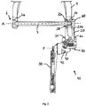
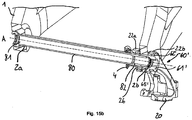
- FIG. 1 shows a perspective view of the rear axle mounted coaxially on the rear axle 6, according to the invention rear derailleur 10. For clarity, the rear wheel and the sprocket set are not shown.
- the rear hub 3 arranged between the two dropouts of the frame 1 and the rear dropout embracing the right dropout 10 are shown.
- the base element 20 is mounted on the frame 1 coaxially with the axis A by means of the adapter 60.
- FIG. 2 shows a section along the axis A of in FIG. 1 illustrated rear derailleur 10 in the rear view.
- the geometric axis A extends along the rear wheel axis 6.
- the base member 20 is by means of the adapter 60 on the right Dropouts attached.
- the adapter 60 passes through the right frame opening 2b.
- the thru axle 7 is inserted into the left frame opening 2a and bolted to the adapter 60.
- the adapter 60 also serves as a counter to the thru axle 7. When the thru axle 7 is tightened, it continues to screw into the adapter 60 and clamps against the frame first
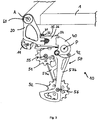
- FIG. 3 shows a side view of the invention mounted on the frame 1 rear derailleur 10 from FIG. 2
- the FIGS. 1 to 3 each show the entire rear derailleur 10 with the base member 20, the pivot mechanism 30, the movable member 40 and the chain guide assembly 50.
- On the base member 20 is a cable guide 11, arranged here in the form of a rotatably mounted at the junction 29c Seilumlenkungsrolle.
- the base member 20 is mounted at its first, upper terminal end coaxial with the rear wheel axle A on the frame 1.
- two axially spaced apart arms of the base member 20 embrace the dropout of the frame 1, so that an arm on the inside of the frame 1 and the other arm on the outside of the frame 1 is arranged.
- the base member 20 is preassembled with the adapter 60 on the frame 1. Further, the base member 20 is coupled to the pivot mechanism 30 at its second lower terminal end.
- the pivot mechanism 30 is formed as a parallelogram four-bar link with an inner pivot arm 35, an outer pivot arm 36 and four pivot axes 31, 32, 33, 34.
- the four pivot axes 31, 32, 33, 34 each extend in planes that intersect the axis A at right angles. In other words, the pivot axes 31, 32, 33, 34 lie in planes that extend parallel to the not shown rift planes (see. FIGS. 11 to 13 ).
- the first and second pivot axes 31, 32 connect the pivot mechanism 30 to the base member 20.
- the third and fourth pivot axes 33, 34 connect the pivot mechanism 30 to the movable member 40.
- Both the base element 20 and the movable element 40 each have two receptacles for the pivot axes.
- the longitudinal axes L1, L2 of the receptacles on the base member 20 and the longitudinal axes of the receptacles on the movable member 40 are aligned as the pivot axes 31, 32, 33, 34 itself orthogonal to the rear wheel axle 6 and the axis A (see. FIGS. 4 to 9 ).
- the chain guide assembly 50 is rotatably connected to the movable member 40 about the axis P and biased in the UZS (backward), so that a not shown here, the chain guide 50 S-shaped continuous chain is tensioned.
- the chain guide assembly 50 includes an upper and a lower Ketten Entrysröllchen 51, 52, which are each rotatably mounted between two cage halves 57 a, 57 b.
- the upper Ketten Entrysröllchen 51 is rotatably disposed at an upper distance from the axis P about the upper axis of rotation 55.
- the lower Ketten Entrysröllchen 56 is rotatably disposed at a lower distance from the P axis about the lower Drehasche 56, wherein the upper Ketten Entrysröllchen 51 is arranged at a smaller distance from the P axis than the lower Ketten Entrysröllchen 52.
- the movable element 40 has a locking element 42 which allows the prestressed chain guide assembly 50 to be fixed relative to the movable element 40.
- the rear derailleur 20 can be mounted without the chain guide assembly 50 snaps backwards due to the bias.
- the chain guide assembly 50 When switching to a smaller pinion, the chain guide assembly 50 rotates about the axis of rotation P of the movable member 40 in the UZS backwards. Conversely, the chain guide assembly 50 rotates forward when switching to a next larger pinion about the rotation axis P against the UZS.
- the upper Ketten Entrysröllchen 51 radially on the pinion or moved away.
- the chain guide assembly 50 In the axial direction, the chain guide assembly 50 is moved by the pivot arms 35, 36 to the pivot axes 31, 32, 33, 34 are pivoted.
- the upper Ketten Entrysröllchen 51 moves together with the entire chain guide assembly 50 in the axial direction inwards or outwards.
- FIG. 4 and 5 show in each case perspective partial sections of the mounted with the aid of the adapter 60 to the frame 1 base member 20 and parts of the hub assembly.
- the first arm 22 a and the second arm 22 b are respectively positioned on one side of the frame 1.
- this is guided along with the hub assembly (here only the hollow shaft 5 is shown) and the hub end cap 4 along the hub guide 27 on the inside of the base member 20.
- the hub guide 27 is formed as a collar with converging guide surfaces.
- the hub end cap 4 abuts radially on the hub guide 27 in its end position. In the axial direction, the hub end cap 4 abuts against the axial hub stop surface 26 on the inside of the base member 20.
- the hub end cap 4 is shown cut.
- FIG. 5 shows a section through the base member 20 with the two adapters 60 embracing arms 22a, 22b.
- the adapter 60 consists of the bolt 61 and the nut 66.
- the bolt 61 is screwed into the nut 66, so that the bolt head 62 and the nut 66 are clamped to the frame 1.
- the adapter 60 is so fixed relative to the frame 1.
- the base member 20 is centered on the adapter 60. In running order, with stuck-through axle 7, the base member 20 is clamped between the hub end cap 4 and the adapter 60 rotatably.
- the base member 20 is in the assembled state in the axial direction only on the hub end cap 4 and the adapter 60 at.
- the base member 20 is indirectly mounted to the frame 1 via the adapter 60.
- the base member 20 and thus the entire rear derailleur 10 is referenced to the hub 4 - and not as usual on the frame first
- FIG. 6 shows the enlarged partial section of the adapter 60 mounted on the frame 1 base member 20 from FIG. 5 ,
- the bolt head 62 and the nut 66 are sized larger than the frame opening 2b.
- the nut 66 has a knurled surface 69, in addition to produce a positive connection to the frame 1 and counteract a twisting of the rear derailleur 10 forward (against the UZS).
- the bolt body 63 has an abutment portion 63a which abuts against the frame hole 2b with little play and a balance portion 63b which has more clearance than the frame hole 2b.
- the compensation region 63b allows the adapter 60 to align in the frame opening 2b along the axis A.
- the bolt 61 has play in the frame opening 2b and can tilt it slightly if the frame opening is not exactly aligned with the axis A.
- FIG. 7 shows the arrangement FIG. 6 with cut adapter 60.
- the adapter 60 has two purposes: 1) The clamp on the frame 1 is made by the screw connection between the bolt 61 and nut 66. Alternatively, the nut could be arranged outside and the bolt inside. It is important that the adapter 60 relative to the frame 1 can be fixed and is adaptable to this in the axial direction. With a thinner frame, the screw connection is tightened further than with a thicker frame. 2) The adapter 60 is only limitedly rotated relative to the base member 20 in UZS and thus provides an anti-rotation. For this purpose, two stops 68a, 68b are arranged on the nut 66, which cooperate with two pins 24a, 24b on the base member 20.
- a rotation of the rear derailleur 10 forward (against UZS) is due to the rotation between adapter 60 and base member 20 only limited possible.
- the anti-twist device replaces the usual B screw and protects against unintentional twisting of the rear derailleur.
- the external thread 64 and the internal thread 65 of the bolt 61 are arranged in different areas along the bolt 61 so as to better absorb forces.
- the plug-in shaft 7 is screwed into the internal thread 65 and pulls the adapter 60, in particular the bolt head 62, against the outside of the frame 1.
- a washer between the bolt head 62 and the frame 1 is arranged.
- FIG. 8 An exploded view of the unassembled base member 20 and the adapter 60 from FIG. 7 , In this view, the internal thread 67 of the nut 66 and the external thread 64 of the bolt 61, which together form the screw connection of the adapter 60, are clearly visible. Alternatively, the bolt could also be screwed directly into a thread of the frame opening. But then frame tolerances would directly affect the rear derailleur, which should be avoided. Furthermore, the bolt foot 63c, which is matched to the first centering opening 23a, and the bolt head 62, which is matched to the second centering opening 23b, can be seen. The abutment surface 63d of the bolt 61 cooperates with the side of the first arm 22a of the base element 20 facing away from here (cf. FIG. 9a ).
- FIGS. 9a and 9b show an outside and inside perspective view of the base member 20 with the first and second centering openings 23a, 23b.
- the first centering opening 23 a is matched to the outer diameter of the bolt foot 63 c of the bolt 61.
- the second centering opening 23b is matched to the outer diameter of the bolt head 61.
- the adapter stop surface 25 can be seen, which cooperates with the abutment surface 63d of the bolt 61.
- the hub abutment surface 26 is arranged. In running condition, the Bolt 61 with the bolt stop surface 63 d against the outside and the hub end cap 4 against the inside of the base member 20 is clamped.
- connection point 29c for a cable guide 11.
- first receptacle 29a for the first pivot axis 31
- second receptacle 29b for the second pivot axis 32 of the pivot mechanism not shown here 30.
- the longitudinal axes L1, L2 of the first and second receptacles 29a, 29b extend in planes which intersect the rear wheel axis A at right angles.
- the four pivot axes 31, 32, 33, 34 of the parallelogram four-bar linkage 30 are therefore aligned orthogonal to the common pinion axis A, regardless of the selected relative position of the derailleur 10.
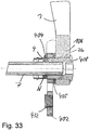
- FIG. 10 shows a partial section through the second embodiment of the inventive derailleur 20 10 with an adjustment.
- the cut passes through the movable member 40 and the chain guide assembly 50.
- the adjustment aid is in the form of the locking member 42 which engages the locking aperture 58 in the outer cage half 57b.
- the UZS pre-tensioned chain guide assembly 50 is fixed relative to the movable member 40 in a predetermined rotational position.
- the predetermined rotational or angular position defines the upper Ketten Entrysröllchen 51 at an ideal distance from a reference pinion of the sprocket set, not shown here.
- To set the rear derailleur 10 this is locked by means of the adjustment. After adjustment, the lock is released so that the chain guide assembly 50 can rotate relative to the movable member 40.
- the base member 20 When tightened thru axle 7, the base member 20 is also fixed rotationally relative to the frame 1. Only the pivot mechanism 30, the movable member 40 and the chain guide assembly 50 of the derailleur 10 move during Shift still relative to the frame 1. When disassembling the thru axle 7 is released, so that the rear derailleur 10 can turn back and the rear wheel can be removed.
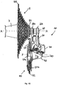
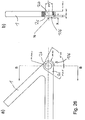
- FIG. 11 and 12 show third embodiments of the rear derailleur 10 according to the invention with limit stops 59a and 59b, which make it possible to dispense with the usual limiting screws 70 (limit screws).
- limit screws 70 are in FIG. 12 still shown.
- the rear derailleur 10 in FIG. 11 is aligned with the largest pinion R12 of the sprocket set R. This position represents the inner maximum position.
- the rear derailleur 10 should not move further in the axial direction.
- the first limit stop 59a is arranged on the chain guide arrangement 50, in particular on the inside of the outer cage half 57b.
- the first limit stop 59a is formed to cooperate with the largest pinion R12.
- the inner limit stop 59a projects beyond the cage 57b in the area of the P axis and abuts in the inner maximum position against the outside of the pinion R12.
- the chain guide assembly 50 can then not be moved further inward with respect to the largest pinion R12 in the axial direction.
- the outer cage half 57b of the chain guide assembly 50 radially extends in the inner maximum position of the derailleur 10 into a region of the largest pinion R12 which is within the radial outer diameter of the largest pinion R12. In the axial direction, the outer cage half 57b extends in the inner maximum position of the derailleur 10 between the largest pinion R12 and its adjacent next smaller pinion R11. In the inner maximum position of the rear derailleur 10 is not one here shown chain in engagement with the largest pinion R12. If the rear derailleur 10 continues to move inwards in the axial direction beyond the inner maximum position, the outer cage half 57b or the inner limit stop 59a abuts against the largest pinion R12 and thus limits the movement of the rear derailleur 10.
- the inner limit stop 59a is here in one piece the outer cage half 57b formed. Multi-part versions of cage and limit stop are also conceivable.
- the movable element may be formed such that it acts as an inner limit stop in the intended, inner maximum position of the derailleur.
- the inner limit stop cooperates with the sprocket set, in particular a pinion or other suitable element associated with the sprocket set, for example a chain guard.
- the derailleur 10 is aligned with the smallest pinion R1 of the sprocket set R.
- the chain guide assembly 50 is rotated much farther back (in the UZS).
- the upper Ketten Entrysröllchen 51 is approximately equidistant from the pinion R1 in the radial direction, as in FIG. 12 from the pinion R12.
- the position shown represents the outer maximum position of the rear derailleur 10.
- the rear derailleur 10 should not move further outward in the axial direction.
- the second limit stop 59b is arranged on the chain guide arrangement 50, in particular the outside of the outer cage half 57b.
- the second limit stop 59 a is formed so as to cooperate with the base member 20.
- the outer side of the outer cage half 57b in the region of the upper chain guide roller 51 acts as a second limit stop 59b.
- the second limit stop 59b abuts in the outer maximum position against the inside of the base member 20.
- the inside of the base member 20 is also the inside of the first arm 22a. The chain guide assembly 50 can then not be moved further outward relative to the base member 20 in the axial direction.
- limit stops 59a, 59b An advantage of the limit stops 59a, 59b is that these fixed stops no longer need to be adjusted, but are already tuned to the sprocket package R.
- the limit screws 70 for adjusting the stops are no longer necessary.
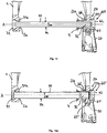
- FIG. 14 shows a sectional view of a fourth embodiment along the axis A in the rear view.
- the frame 1, the thru-axle 70, the right hub end cap 4 and selected parts of the derailleur are shown in this illustration. All parts to be seen are shown cut.
- the base member 20 is fixed by means of the adapter 60 at the right dropout.
- the bolt 61 passes through the right frame opening 2b and is screwed to the nut 66.
- the plug-in shaft 70 is inserted with its first end 71 in the left frame opening 2a and screwed with its second end 72 in the pin 61 of the adapter 60.
- the adapter 60 or the bolt 61 serves as a counter to the plug-in axis 70.
- the outer diameter 74 of the plug-in shaft 70 is dimensioned smaller than the frame opening 2a. The gap is balanced with a bushing 71a.
- the first axle end 71 has a head with a larger diameter than the frame opening 2a, and can not slip through the frame opening 2a.
- the head diameter decreases continuously from the first end 71 to the body or shaft of the through axle 70 down to the outer diameter 74.
- the transition is at a 45 degree angle. Other angular dimensions, in particular 90 degrees, are also conceivable.
- the inner arm 22 a of the base member 20 is fixed in the axial direction between the right hub end cap 4 and the bolt 61.
- the inner arm 22a of the base member 20 is moved radially on the centering portion of the bolt 61 (refer to details in FIG FIG. 7 and 8th ) and the outer arm 22b is centered on the bolt head 62.
- the plug-in shaft 70 shown has an outer diameter 74 of 12 mm and an inner diameter 75 of 7 mm. This results in a thru-axle thickness of 2.5 mm.
- the embodiment of the plug-in axis 70 in FIG. 14 corresponds essentially to the previous figures, but here again directly to a thru axle 80 according to FIG. 15a faced with an enlarged outer diameter 84 and a differing centering.
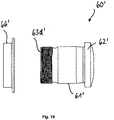
- FIG. 15a shows a sectional view of a fifth embodiment, which differs due to the thru-axle 80 with an enlarged outer diameter 84 in several points from the previous embodiment.
- the thru-axle 80 shown has an outer diameter 84 of 15 mm and a first inner diameter 85 of 12 mm. This leads to a first wall thickness W85 of 1.5 mm. All parts shown are cut.
- the frame 1 with its frame openings 2a and 2b, the hub assembly only partially shown here with the hub end cap 4 and the base member 20 of the derailleur are unchanged. Only the adapter 60 'must be adapted to the enlarged outer diameter 84 of the thru axle 80. To record the thru-axle 80, the diameter of the Internal thread 65 'of the bolt 61' adapted to the outer diameter 84. In addition, the centering area (see centering area 63 c of the preceding embodiments) on the bolt 61 'falls away. As a result, the base member 20 directly contacts the outer peripheral surface of the thru-axle 80.
- the inner arm 22a of the base member 20 is centered directly on the through axle 80, and not on the adapter 60 as in the previous examples.
- the outer arm 22b of the base member is centered unaltered on the outer circumference of the bolt head 62 '.
- the referencing of the base member 20 in the axial direction and in the radial direction is independent of the frame 1.
- the base member 20 between hub end cap 4 and the adapter 60 ' in particular the abutment surface 63d' of the bolt 61 '(see FIG. 19 ).
- the inner arm 22a of the base member 20 is centered directly on the through axle 80 and the outer arm 22b on the adapter 60 ', in particular on the bolt head 62'.
- the wide independence of frame tolerances allows a precise alignment of the derailleur even if the two frame openings 2a and 2b are not exactly aligned.
- the transition between the head at the first end 81 of the thru axle 80 to the thru axle body with the outer diameter 84 is rectangular here.
- the outer diameter 84 of the plug-in axis 80 corresponds approximately to the frame opening 2a.
- the thru-axle 80 is guided through the opening 2a with less play.
- the sleeve 91a has a 45 degree angle and serves to center the through-axle 80 in the frame opening 2a. This socket could also be formed at a different angle.
- FIG. 15b an external perspective view of the sectional view FIG. 15a ,
- the hub end cap 4 abuts axially against the hub abutment surface 26 of the base member 20.
- FIG. 16 is an enlarged detail view of the right dropout of the frame 1 from FIG. 15b shown.
- the second end 82 of the Thru axle 80 is screwed into the internal thread 65 'of the bolt 61' of the adapter 60 '.
- the inner arm 22a of the base element 20 lies with its first centering opening 23a in the radial direction directly on the outer circumference of the plug-in axis 80. In the axial direction, the inner arm 22a is fixed between the hub end cap 4 and the abutment surface 63d 'of the bolt 61'.
- the nut 66 ' substantially corresponds to the previous embodiments.
- FIG. 17 corresponds to the view FIG. 16 , wherein for better clarity, the hub end cap and the adapter nut have been hidden.
- the outer arm 22b of the base member 20 is centered unchanged with its second centering hole 23b on the outer circumference of the bolt head 62 '.
- FIG. 18 shows the arrangement FIG. 17 without the bolt.
- the centering of the base member 20 on the thru-axle 80 is particularly clear.
- the second end 82 of the plug-in axis 20 passes through the inner arm 22a of the base member 20.
- the external thread 83 of the plug-in axis 80 is in the assembled state between the first and the second arm 22a, 22b of the base member 20.
- the surface 87 of the thru-axle 80 is machined at least in the contact region between the base member 20 and thru-axle 80.
- This centering surface 87 is, for example, finely turned, ground and / or coated. Due to the complex processing, the centering surface 87 is kept as narrow as possible. However, the centering surface 87 must be at least as wide as the first centering hole 23 a of the first arm 22 a of the base member 20.
- the centering surface 87 of the plug-in shaft 80 in the assembled state reaches at least into the area of the bolt 61 ', so that the bolt foot comes to rest on the centering surface 87.
- This embodiment allows a precise centering of the bolt 61 'on the thru-axle 80.
- the centering by screwing the external thread 83 of the thru-axle 80 into the internal thread 65' of the bolt 61 'alone is not precise enough due to the thread play.
- the centering surface 87 takes the game between the bolt 61 'and thru axle 80 out.
- a particularly rigid connection between the thru axle 80 and the pin 61 ' is possible.
- the centering surface 87 should have a minimum width so that tolerances depending on the depth of engagement, depending on the hub assembly and frame width, can be compensated and the base member 20 always comes to rest on the surface 87.
- An axial width of the centering surface 87 of about 2.5 mm (or more) is sufficiently wide and can be made relatively quickly and inexpensively.
- Another centering surface could be attached to the outermost second end of the thru-axle, which also cooperates with the pin and results in an even stiffer connection.
- the outer surface of particularly high-quality thru axles could also be completely reworked.
- FIG. 19 shows an enlarged exploded view in the uncut rear view of the adapter 60 ', consisting of the bolt 61' and the nut 66 '.
- the adapter 60 ' substantially corresponds to the adapter 60 of the previous embodiment in the FIGS. 1 to 12 why only the differences are discussed here.
- the enlarged in diameter and adapted to the 15 mm thru-axle 80 internal thread is not visible in the rear view.
- the stop 63d ' forms the inner axial end of the bolt 61 '.
- the remaining outer dimensions of the bolt 61 ' are unchanged and matched to the base member 20.
- a thru-axle 80 according to the fifth embodiment is shown in an uncut rear view in FIG FIG. 20a and in a sectional view taken along the axis A in FIG FIG. 20b shown.
- the thru-axle 80 has an outer diameter 84 of 15 mm.
- the overall axial width from the first end 81 to the second end 82 varies depending on the hub standard used and the constraints. Typical hub widths from left to right hub end caps are 142 to 148 mm.
- the external thread 83 and the centering surface 87 are arranged in the region of the second axle end 82. The centering surface 87 is located axially further inwardly than the external thread 83.
- the centering surface 87 begins at a distance 88 of about 13.5 mm and ends at a distance 88 of about 16 mm from the second plug axis end 82.
- the centering surface 87 has an axial width B87 of about 2.5 mm.
- the axial width B83 of the external thread 83 measures about 10 mm.
- the thru-axle 80 has an outer diameter 84 of 15 mm. Only the first end 81 has a larger head diameter.
- a first inner diameter 85 of the plug-in axis 80 is 12 mm. This results in a first wall thickness W85 of about 1.5 mm.
- the first wall thickness W85 extends over a large part of the axial width of the plug-in axis 80.
- the second inner diameter 86 is smaller than the first inner diameter 85. From the second inner diameter 86 results in a second wall thickness W86, which is greater than the first wall thickness W85.
- the second wall thickness W86 is sized at about 2.4 mm.
- the second inner diameter 86 and the enlarged second wall thickness W86 is just in the areas of Thru axis 80 arranged, which are heavily loaded. In particular, in the region of the external thread 83.
- the area of the centering surface 87 has an increased wall thickness W86, because here the base member 20 rests on the plug-in axis 80 and correspondingly larger forces act.
- the transition between the first and second inner diameter W85, W86 is continuous.
- the second inner diameter 86 extends from the outermost second axle end 82 in the axial direction over a width B86 of about 18 mm.
- first end 81 with enlarged head diameter From the first end 81 to the second end 82 of the plug-in axis 80, the following areas are lined up: first end 81 with enlarged head diameter, right-angled transition to the outer diameter 84, first inner diameter 85 with the resulting wall thickness W85, transition from the first inner diameter 85 to the second inner diameter 86 with the resulting wall thickness W86, centering surface 87, external thread 86 and second plug axis end 82nd
- FIG. 21 shows a sectional view of a Häradachsan Aunt with a thru axle 80 according to the fifth embodiment. All parts are shown cut.
- the thru axle 80 engages in the assembled state, the frame opening 2a, the hub assembly and the driver 100 and is in the rear derailleur, in particular the adapter 60 'is screwed.
- the derailleur (shown only partially here) is attached via the base member 20 and the adapter 60 'to the right dropout of the frame 1.
- the hub assembly With the thru axle 80, the hub assembly is attached to the frame 1.
- the base member 20 is braced against the hub assembly, in particular the right hub end cap 4 in the axial direction.
- the hub arrangement includes, among other things, the left-hand side Hub end cap 8, the hub bearing 9, the hub shell 3, the hub axle 5 and the right hub end cap 4.
- FIG. 22 shows selected parts of the Hinterradachsan Aunt FIG. 21 , For clarity, the driver and most parts of the hub assembly have been removed here. Only the hub axle 5 and the hub bearing 9, consisting of the hub bearings 9a, 9b of the hub assembly designed as roller bearings, are shown. The thru axle 80 is inserted with little play in the hub axle 5. The hub bearings 9a, 9b and the driver bearings 109a, 109b are fitted on the hub axle 5. All parts are shown cut.
- FIG. 23 shows the sectional view of Hinterradachsan Aunt FIG. 22 without the bearings.
- the thru-axle 80 with an outer diameter 84 of 15 mm is inserted into the hub axle 5 with little play.
- the inner diameter d5 of the hub axle 5 is slightly more than 15 mm.
- the outer diameter D5 of the hub axle 5 is about 17 mm.
- the wall thickness W85 of the plug-in axle 80 is greater than the wall thickness W5 of the hub axle 5.
- the wall thickness W85 of the plug-in axle 80 is approximately 1.5 mm and thus 1.5 times the hub axle 5. This leads to a relatively balanced ratio of the area moments of inertia ,
- FIG. 24a shows a partial section through selected parts of a Häradachsan Aunt with a thru axle 90 according to the sixth embodiment. Except the thru axle 90, all parts are shown cut.
- FIG. 24b shows the partial section FIG. 24a in a perspective exterior view.
- the through axle 90 passes through the left frame opening 2a, the hub end caps 8, 4 and the hub axle 5 with little play.
- the second axle end 92 is screwed with the external thread 93 in the adapter 60 'of the rear derailleur.
- the first Outer diameter 94a of the plug-in axle 90 is slightly smaller than the inner diameter of the hub axle 5.
- the plug-in axle 90 has the first outer diameter 94a in the areas of increased load. These are in particular the plug-axis ends 91, 92 and the areas of the bearings 9a, 9b, 109a, 109b.
- the remaining areas of the plug-in axis 90 have a second, reduced outer diameter 94b.
- the thru-axle 90 according to the sixth embodiment is in an uncut rear view in FIG. 25a and in a sectional view taken along the axis A in FIG FIG. 25b shown.
- the thru-axle 90 differs from the thru-axle 80 primarily in that it has a reduced wall thickness W94b in large areas in order to save weight.
- the thru-axle 90 has a first outer diameter 94a of 15 mm and a first inner diameter 95 of 12 mm.
- the first outer diameter 94a of 15 mm was reduced to a second outer diameter 94b of 14 mm.
- the first inner diameter 95 remains unchanged. This results in the region of the first outer diameter 94a, a first wall thickness W94a of 1.5 mm and in the region of the reduced outer diameter 94b, a second, reduced wall thickness W94b of 1 mm.
- the thru-axle 90 only has the larger outer diameter 94a and the greater wall thickness W94b in the axial areas which are subject to a greater load.
- the plug-in axis 90 in the region of the second end 92 has a second smaller inner diameter 96, which is about 10 mm. From the second inner diameter 96 results in a third wall thickness W96, which is greater than the first and the second wall thickness W94a, W94b.
- the second inner diameter 96 or the enlarged second wall thickness W96 is arranged in the heavily loaded region of the external thread 93 and the centering surface 97.
- first end 91 with increased head diameter right-angled transition to the first outer diameter 94a, first inner diameter 95 with the resulting wall thickness W94a in the more heavily loaded areas, between the reduced outer diameter 94b with the resulting reduced wall thickness W94b, transition from the reduced outer diameter 94b to the second inner diameter 96 with the resulting wall thickness W96, centering surface 97, external thread 96 and second axle end 92nd
- the reduced outer diameter 94b can be made particularly easily by twisting off the excess material on the outer side of the thru-axle 90.
- a reduced wall thickness could also be realized by a third, enlarged inner diameter. This material is removed or saved on the inside of the thru axle and not on the outside. The effect of weight saving would be the same.
- the thru axles 80, 90 with an enlarged outer diameter of 15 mm despite a smaller wall thickness of 1 mm to 2 mm have a much higher area moment of inertia compared to the thru axles 70 with a 12 mm outer diameter.
- the stiffness is increased and / or the weight is reduced.
- Another embodiment not shown here, as it could be used especially for e-bikes, is a thru-axle with an outer diameter of 15 mm and an inner diameter of 11 mm.
- the area moment of inertia is somewhat reduced but significantly reduced in weight.
- the more even distribution of the area moment of inertia on the through axle and hub axle leads to an overall more stable axle arrangement, because the maximum stresses on the outer skin of the hub axle are lower.
- both the stiffness and the weight can be further influenced.
- Preferred materials for the thru axle are aluminum, titanium or steel.
- the modular system allows a simple and cost-effective replacement of the axle 70, 80, 90th Depending on the type of bike and load either a stiffer or lighter thru axle can be selected. Only the adapter 60, 60 'must be adapted to the selected thru axle 70, 80, 90, the hub assembly, the driver 100, the base member 20 and the remaining parts of the rear derailleur can be used unchanged and are not affected by the change of the thru axle.
- the wall thicknesses of the hub and thru axles mentioned in the embodiments described above are designed for production from aluminum.
- the statements made regarding the moment of inertia are independent of material. As long as the same material is used for the thru axle and the hub axle, the aforementioned wall thickness ratios can be maintained.
- the wall thicknesses can be adjusted according to the maximum stresses.
- a thru axle made of titanium and a hub axle made of aluminum could be made. Then the thru-axle could be formed thin-walled according to the permissible yield strengths.
- the above-described embodiments of the new (second) type rear derailleur 10 according to the present invention can hardly be mounted on a conventional bicycle frame designed for attachment of a conventional rear derailleur by means of a shift eye non-coaxial with the axle.
- a rear derailleur according to the invention of the new type (hereinafter referred to as a rear derailleur of the second type) is thus the conventional rear derailleur of the bicycle according to FIG. 13 (hereinafter referred to as the rear derailleur of the first type) can not replace.
- the rear derailleur 10 of the second type itself and associated components, such as the adapter 60, not on the conventional frame of FIG. 13 assemble.
- the stub axle 7, the hollow shaft 5 and the hub end cap 4 and thus the entire hub assembly and in consequence the rear wheel of the described Embodiments are not due to the mountability of the adapter 60 on the conventional bicycle frame the FIG. 13 can be mounted.
- the invention underlying the rear derailleur of the second type implicitly implements a specific design of the bicycle frame 1 to be used with it for the rear wheel axle assembly at the rear support portions (dropouts) for mounting the adapter 60 and around the inwardly disposed first arm 22a of FIG Base member 20 together with the other, the hub associated or assigned components between the dropouts and to be able to mount.
- the first arm 20a of the base member 20 will regularly be axially thicker (eg, with an axial thickness in the range of about 7 to 9 mm, more specifically, for example, with an axial thickness of about 8 mm, respectively) with conventional tolerances) as a conventional derailleur hanger to be positioned on the inside of the associated dropout, which typically could have an axial thickness of about 4.5 to 5.5 mm, for example an axial thickness of about 5 mm.
- the present invention thus provides not only the rear derailleur 10 of the second type with the adapter 60 as advantageous innovations, but at least implicitly also provided for the assembly of the adapter 60 and the rear derailleur 10 of the second type bicycle frame 1.
- the invention Based on these components a set of components ready and disclosed here with reference to the FIGS. 1 to 12 and 14 to 26 several embodiments of such a set, each comprising at least one rear derailleur 10 of the second type, at least one adapter 60 and a bicycle frame 1 suitable for mounting these components.
- the respective set of components may also include the associated other components of the hub and rear axle assemblies, such as the through axle 7, the hollow axle 5 and the hub end cap 4 of the embodiment of FIG Figures 1 to 9b or the corresponding components of the other embodiments.
- a bicycle equipped with a derailleur provided with a rear derailleur of the second type can be provided.
- the conventional bicycle frame according to FIG. 13 difficult to be equipped with a rear derailleur of the second type.
- the bicycle frame provided by the invention for mounting the rear derailleur of the second type can hardly be equipped with a rear derailleur of the first type, at least using a conventional shift eye.
- a conventional derailleur hanger will not have a sufficient axial thickness to provide the necessary clamping force between the dropouts for clamping the rear wheel axle assembly.
- conventional switch eyes are likely to lack suitable, based on each other interfaces of the Heidelbergauges one hand, and the on the other hand assigned dropout on the other hand barely be positioned on the inside of the dropout and properly assembled.
- FIG. 26 shows an example of a preferred embodiment of the rear right dropout of a bicycle frame, which is intended for the assembly of the rear derailleur according to the invention of the new (second) type.
- a mounting hole 2b having an opening diameter of about 20 mm is provided, which widens to form a vertical body edge on the inside to a receiving recess 2c, which forms an interface for the first (inner) arm 22a of the base member 22.
- the recess 2c may have an axial depth of about 4 mm
- the area of the dropout having the opening 2b may, for example, have an axial depth of about 12.5 mm, corresponding to a total dropout thickness in this range of about 16.5 mm
- Concerning the axial dimension x between the body edge bordering the recess 2c and the stop element N of the rear wheel axle arrangement receiving the clamping force between the dropouts (for example the this side end of the hollow axle or hub end cap or axle nut or a comparable functional part), according to the above-mentioned design possibilities for the first (FIG.
- the inner) arm 20a of the base member 20 at an axial distance of about 7 to 9 mm, more specifically, for example, to an axial distance of about 8 mm between the body edge and the stop element N thought.
- the first arm 20a is in the region of the recess 2c preferably designed so that in the not yet tightened pre-assembly rotatability of the base member 20 is given over a certain angular range relative to the recorded in the mounting hole 2b adapter 60 and relative to the dropout, as above described.
- a set of components provided by the invention additionally comprises a rear derailleur of the conventional first type (for example according to FIG. 13 ), as well as an associated derailleur hanger, which permits proper mounting of the rear derailleur of the first type on the frame actually intended for the assembly of a rear derailleur of the second type.
- the invention specifically provides, as it were, an adapter function for adapting the rear derailleur of the first type to the derailleur hanger (also referred to herein as the mounting element) which fulfills the bicycle frame designed for mounting the rear derailleur of the second type.
- the Figures 27 and 28 show a preferred embodiment of an inventive support member or derailleur 100.
- the derailleur 100 is advantageously made of several parts, with a tab-like metal part 102 and the axial thickness of the Wegauges100 in the region of the clamping between the support sections or dropouts of the frame increasing spacer 104, which has a resting on the inside of the metal part spacer portion 105.
- the spacer part is designed according to a particularly preferred, but not mandatory embodiment as a plastic part, and it can in addition to the function the adaptation of the axial thickness to the conditions of the respective bicycle frame also perform beneficial additional functions, as realized in this example.
- the spacer or plastic part 104 serves to adapt to the interface of the associated rear dropout 106 of the frame.
- the plastic part 104 serves to adapt to the geometry of the recess 2c.
- the plastic part 104 has an outer circumference, which fits straight into the inner circumference of the recess 2c, so that the derailleur hanger 102 is secured in the frame mounted state against rotation relative to the frame.
- the attachment of the Wegauges 102 on the frame is made by a bolt-like adapter 108 which is screwed from the outside of the frame with its male threaded portion 110 in an internal thread 121 of a mounting hole 120 of the metal part 102 and this by an associated passage opening 122 of the spacer portion 105 of the plastic part 104th extends.
- the plastic part 104 has an in the axial direction to the other rear dropout projecting collar 124 which serves as an assembly and positioning aid for the hub assembly or its hollow shaft in the course of assembly of the rear wheel.
- the integrally with the spacer portion 105 and one edge of the metal part 102 cross collar 124 provides for this purpose a guide and positioning surface on which the hollow axle can slide to bring them into the correct position, in which then the assembly by inserting the associated , Preferably designed as a plug axis inner axis through the hollow shaft and screwing the thru axle with the adapter 108 can be completed.
- the thru-axle is here screwed with a screw-in into an internal thread 126 of the adapter 108, analogous to that described in the assembly of a rear derailleur of the new (second) type.
- the metal part 102 has a holding opening 130 in a lower region, in which a screw-in sleeve 132 is fixed or fixed, for example held in a press fit.
- the screw-in sleeve 132 has at a axially inner end a radially projecting collar 134 which rests on the inside of the metal part 102 and so tightening the base member of a rear derailleur of the conventional (first) type on the outside of the metal part 102 in a known per se and way allows.
- the screwing is done with the internal thread 136 of the screw 132.
- a screw with an internal thread of the holding hole 130 may be provided, waiving the screw-in.
- the metal part 102 may - as realized in the embodiment - have one or more openings or recesses, which serve to save weight.
- Such an opening 140 is shown in the figures in a central region of the Heidelbergauges 100.
- at least one further additional part associated with the derailleur hanger may be provided, as illustrated in the starting example on the basis of the auxiliary part 142, which is also referred to as the auxiliary part. It can also be a plastic part.
- the auxiliary part 142 is designed with a holding section 144 which is inserted into a holding opening 146 of the metal part 102 provided next to the mounting opening 120.
- This auxiliary part 142 also serves to adapt to the interface of the dropout and especially for supporting rotational forces on the frame, which act on the derailleur hanger relative to the dropout.
- the auxiliary part 142 of the holding portion 144 protruding fitting and stop portions 148 and 150.
- the spacers 124 in particular plastic parts 124, could have different axial thicknesses of the spacer section 105 and different shaped collars 124.
- the bearing part of the Wegges 100 performing metal part 102 is preferably designed as a stamped part and punched, for example, from about 5 mm thick sheet.
- the wall thickness ratios are thought to be such that even high quality alloys (e.g., AL 7075 T6) can be processed.
- AL 7075 T6 high quality alloys
- the already mentioned opening 140 in the central region of the metal part 102 can also fulfill a targeted weakening function to provide a kind of predetermined breaking point or predetermined bending point for the metal part 102, so that damage elsewhere, especially the rear derailleur and the bicycle frame, are avoided as possible.
- the common axial thickness of the metal part 102 with the spacer portion 105 correspond to the axial clearance x, so that the derailleur hanger 100 can replace the first (inner) arm 20a of the new (second) type base member 20, ensuring substantially identical Clamping and clamping conditions.
- the inner end of the adapter 108 which can also be labeled as axle pin, is flush with the inside of the metal part 102.
- the stop element N of the rear wheel axle arrangement can then be fixed to the inner end of the adapter 108 and / or strike against the inside of the metal part 102.
- the stop element N abuts against a stop surface of the inner end of the adapter 108.
- the internal thread in the opening 220 of the metal part 202 is omitted.
- FIGS. 31 and 32 show two further embodiments of a support member or Wegauges 300 and 400, which are very similar to the embodiment of Figures 27 and 28 are executed.
- the frame 1 is executed at its rear right dropout something different than in the embodiment of FIG. 26 ,
- FIG. 33 is an enlarged view of the area of the right dropout, in addition, a hub end cap 4 is shown as a stop element N of Deutschenchsan angel.
- the hub end cap 4 abuts an inner stop surface at the inner end of the adapter 408 and supports the acting clamping force on this adapter, which in turn supports the clamping force on the metal part 402 and the spacer portion 405 of the plastic part 404 on the inside of the dropout of the frame 1.
- auxiliary part 142 or 242 of the embodiments of the FIGS. 27 to 30 is complementary to the FIG. 34 referenced, which shows such an auxiliary part without loss of generality in different views.
- such an auxiliary part can also have a completely different shape.
Abstract
Gemäß einem von mehreren Aspekten der Erfindung stellt diese ein auch als Schaltauge bezeichenbares, gewünschtenfalls mehrteiliges Halterungselement (100) bereit, welches an einer axialen Innenseite eines zugeordneten Halterungsabschnitts der für die Halterung einer Achse einer Hinterradachsanordnung eines hinteren Laufrads dienenden hinteren Halterungsabschnitte eines Fahrradrahmens positionierbar ist, um ein hinteres Schaltwerk einer Kettenschaltung an dem Fahrradrahmen zu montieren. Das Halterungselement (100) umfasst einen ersten Abschnitt, der eine der Achse zugeordnete Öffnung oder Aussparung (120, 122) aufweist und im montierten Zustand unter Mitwirkung weiterer Komponenten einer zwischen den hinteren Halterungsabschnitten wirkenden Spannkraft ausgesetzt ist, und einen zweiten Abschnitt, der eine gegenüber der Öffnung oder Aussparung (120, 122) im montierten Zustand gegenüber der Achse radial versetzte Montageöffnung (130) aufweist, an der ein Anschlussende eines Basiselements des hinteren Schaltwerks festlegbar ist. Erfindungsgemäß ist vorgesehen, dass ein die Montageöffnung umgebende Anlagefläche des zweiten Abschnitts, die dafür vorgesehen ist, eine Auflagerfläche für das Anschlussende des montierten Basiselements zu bilden, gegenüber einer die Öffnung oder Aussparung umgebenden Anlagefläche des ersten Abschnitts auf der gleichen Seite des Halterungselements in Richtung zur anderen Seite des Halterungselements versetzt ist.According to one of several aspects of the invention, this also provides a hanger-signable, optionally multi-piece support member (100) positionable on an axial inner side of an associated support portion of the rear support portions of a bicycle frame for supporting an axle of a rear wheel axle assembly of a rear wheel, to mount a rear derailleur of a derailleur to the bicycle frame. The support member (100) includes a first portion having an axis associated with the opening or recess (120, 122) and is exposed in the assembled state in cooperation with other components acting between the rear support portions clamping force, and a second portion, the one opposite the opening or recess (120, 122) in the mounted state relative to the axis radially offset mounting opening (130) on which a terminal end of a base member of the rear derailleur can be fixed. According to the invention, a contact surface surrounding the mounting opening of the second section, which is intended to form a bearing surface for the connection end of the mounted base element, opposite a bearing surface of the first section surrounding the opening or recess on the same side of the support element in the direction of offset from the other side of the support member.
Description
Die vorliegende Erfindung betrifft allgemein ein hinteres Schaltwerk einer Fahrradkettenschaltung und die Art und Weise der Montage des hinteren Schaltwerks in Relation zu einer Hinterradachse an einem Fahrradrahmen.The present invention generally relates to a rear derailleur of a bicycle chain transmission and the manner of mounting the rear derailleur in relation to a rear wheel axle on a bicycle frame.
Die vorliegende Erfindung betrifft nach einem Aspekt der Erfindung spezieller die Montage des hinteren Schaltwerks am zugeordneten hinteren, typischerweise rechten Halterungsabschnitt (im Folgenden entsprechend der üblichen Fachsprache auch als "Ausfallende" bezeichnet) des Fahrradrahmens mittels eines sogenannten Schaltauges, ganz allgemein sowie - nach einem weiteren Aspekt der Erfindung - als Alternative zu einer koaxialen Montage des hinteren Schaltwerks in Bezug auf die Hinterradachse unter Verwendung eines speziell dafür ausgeführten hinteren Schaltwerks.More specifically, according to one aspect of the invention, the present invention relates to the assembly of the rear derailleur on the associated rear, typically right-hand support section (hereinafter also referred to as "dropout") of the bicycle frame by means of a so-called shift eye, more generally, and after another Aspect of the invention - as an alternative to a coaxial assembly of the rear derailleur with respect to the rear axle using a specially designed rear derailleur.
Üblicherweise werden hintere Schaltwerke am rechten Ausfallende des Rahmens mit Hilfe eines Schaltauges befestigt. Bei dem Schaltauge handelt es sich regelmäßig um ein gegenüber dem Fahrradrahmen gesondertes Halterungselement (vgl. beispielsweise
Für die Montage des hinteren Schaltwerks wird das gegenüber dem Fahrradrahmen gesonderte Schaltauge regelmäßig an seinem einen Ende koaxial mit der Hinterradachse am Rahmen festgelegt und an seinem anderen Ende mit dem Basiselement (auch als "B-Knuckle" bekannt) des Schaltwerks verbunden. Das Basiselement ist relativ zum Schaltauge um eine Drehachse (B-Achse) drehbar, um das Schaltwerk in eine relative SollPosition in Bezug auf die Hinterachse und damit ein Ritzelpaket eines hinteren Laufrads dreheinstellen zu können. So kann eine an einem beweglichen Element (auch als "P-Knuckle" bekannt) um eine Drehachse (P-Achse) drehbar gelagerte Kettenführungsanordnung in die richtige Ausgangsstellung gebracht werden. Das bewegliche Element ist über einen Bewegungsmechanismus, insbesondere Schwenkmechanismus, mit dem Basiselement verbunden.For the assembly of the rear derailleur which is separate from the bicycle frame derailleur is regularly set at one end coaxial with the rear axle on the frame and connected at its other end to the base member (also known as "B-Knuckle") of the derailleur. The base member is rotatable relative to the derailleur hanger about an axis of rotation (B-axis) to rotate the derailleur to a relative desired position with respect to the rear axle and thus a sprocket set of a rear wheel. Thus, a chain guide arrangement rotatably mounted on a movable element (also known as "P-Knuckle") about a rotation axis (P-axis) can be brought into the correct starting position. The movable element is connected via a moving mechanism, in particular pivoting mechanism, to the base element.
Schaltaugen unterscheiden sich je nach Hersteller und Anbringungsart stark voneinander. Sie können - wie schon erwähnt - einteilig mit dem Rahmen ausgebildet sein oder - wie hier von besonderem Interesse - als separates Bauteil vorliegen. Separate Schaltaugen werden in der Regel entweder über Schnellspannachsen oder über Steckachsen am Rahmen geklemmt. Es ist sowohl die Klemmung auf der Rahmenaußenseite, als auch auf der Rahmeninnenseite möglich. Das führt dazu, dass das Schaltwerk je nach verwendetem Schaltauge eine andere Position relativ zur Hinterradachse und auch zum Ritzelpaket einnimmt. Diese Positionsunterschiede in axialer als auch in radialer Richtung machen die Schaltwerksauslegung und dessen Montage kompliziert. Das Schaltwerk muss je nach Schaltauge neu eingestellt werden. Durch das zusätzliche Bauteil kommen Toleranzen hinzu, die sich negativ auf die Positionierungsgenauigkeit des Schaltwerks auswirken.Derailleurs differ greatly depending on the manufacturer and mounting method. They can - as already mentioned - be formed integrally with the frame or - as here of particular interest - be present as a separate component. Separate breaker eyes are usually clamped either via quick release axles or via thru axles to the frame. It is both the clamping on the frame outside, as well as on the frame inside possible. This leads to the fact that the rear derailleur occupies a different position relative to the rear wheel axle and also to the sprocket set, depending on the derailleur hanger used. These positional differences in the axial as well as in the radial direction make the rear derailleur design and its assembly complicated. The rear derailleur must be readjusted depending on the derailleur hanger. The additional component adds tolerances which have a negative effect on the positioning accuracy of the derailleur.
Außerdem sind Schaltaugen, gerade als separate Bauteile, schadensanfällig und oftmals instabil. Bei großen Ritzelpaketen und entsprechend großen Schaltwerksdimensionen treten erhöhte Hebelkräfte auf, die von einem austauschbaren Schaltauge nur ungenügend aufgenommen werden können. Darüber hinaus wirken sich die vergrößerten Schaltwerksdimensionen mit den verlängerten Hebelverhältnissen zusätzlich negativ auf die Positionierungsgenauigkeit des Schaltwerks aus. Im Konflikt dazu steht, dass gerade eine erhöhte Anzahl von eng nebeneinander angeordneten Ritzeln eine erhöhte Positionierungsgenauigkeit verlangt.In addition, break eyes, especially as separate components, are susceptible to damage and often unstable. With large sprocket sets and correspondingly large derailleur dimensions, increased lever forces occur, which can only be insufficiently absorbed by a replaceable derailleur hanger. In addition, the enlarged derailleur dimensions with the extended lever ratios additionally have a negative effect on the positioning accuracy of the derailleur. The conflict is that just requires an increased number of closely spaced pinions an increased positioning accuracy.
Das Hinterrad umfasst unter anderem eine Hinterradnabe mit einer hohlen Nabenachse (auch Hohlachse genannt). Zur Befestigung des Hinterrads am Rahmen wird eine separate Steckachse oder Schnellspannerachse durch die Nabenachse der Hinterradnabe geführt und mit dem Rahmen verspannt.The rear wheel includes, among other things, a rear hub with a hollow hub axle (also called hollow axle). To attach the rear wheel to the frame, a separate thru axle or quick release axle is guided through the hub axle of the rear hub and braced with the frame.
Es sind auch Schaltwerker zur koaxialen Montage an der Hinterradachse bekannt, die ohne ein Schaltauge auskommen. Beispielsweise beschreiben die
Üblicherweise umfassen die bekannten Schaltwerke zur koaxialen Montage an der Hinterradachse ein Basiselement mit einem Befestigungsende, welches eine Öffnung zur Aufnahme einer Achse aufweist. Das Befestigungsende wird ähnlich wie ein Schaltauge entweder außen oder innen am Rahmen befestigt. Dazu wird es am Rahmen kraftschlüssig mittels Steckachse oder Schnellspannachse geklemmt. Diese bekannten koaxialen Ausführungen weisen jedoch Mängel auf.Usually, the known derailleurs for coaxial mounting on the rear wheel axle comprise a base member with a mounting end having an opening for receiving an axle. The attachment end is similar to a derailleur hanger attached either outside or inside the frame. For this purpose it is frictionally by means of Thrust axle or quick-release axle clamped. However, these known coaxial designs have shortcomings.
Zum einen ist die mangelnde Stabilität der Anordnung zu nennen. Moderne Ritzelpakete umfassen eine immer weiter steigende Anzahl von elf oder mehr Ritzeln. Um diese mit dem koaxial zu Hinterradachse montierten Schaltwerk bedienen zu können, wird die Schaltwerksdimension erhöht. Damit einhergehend steigen auch die auf das Schaltwerk wirkenden Hebelkräfte, so dass das Schaltwerk zum Verkippen gegenüber den Rotationsebenen der Ritzel neigt. Nur ein exakt vertikal unter dem Ritzelpaket stehendes Schaltwerk lässt sich präzise schalten.On the one hand, the lack of stability of the arrangement can be mentioned. Modern sprocket packages include an ever-increasing number of eleven or more sprockets. In order to operate this with the rear axle mounted coaxially to the rear derailleur, the derailleur dimension is increased. Along with this, the lever forces acting on the rear derailleur also increase, so that the rear derailleur tends to tilt relative to the rotational planes of the pinions. Only a rear derailleur that is exactly vertical under the sprocket set can be switched precisely.
Zum anderen ist die Abhängigkeit von Rahmentoleranzen problematisch. Da herkömmliche Schaltwerke für die zur Hinterradachse koaxiale Montage direkt am Rahmen befestigt und gegenüber diesem referenziert sind, wirken sich Fertigungstoleranzen des Rahmens auch direkt auf das Schaltwerk aus. Darunter leidet die Positionierungsgenauigkeit und Einstellbarkeit des Schaltwerks.On the other hand, the dependence on frame tolerances is problematic. Since conventional derailleurs for the coaxial to the rear axle mounting mounted directly on the frame and referenced against this, manufacturing tolerances of the frame also affect directly on the rear derailleur. This suffers the positioning accuracy and adjustability of the derailleur.
Im Hinblick auf diese und andere Nachteile des Stands der Technik hat die Anmelderin SRAM Deutschland GmbH einen neuen Typ eines hinteren Schaltwerks zur koaxialen Montage an einer Hinterradachse entwickelt, auf welches anhängige Patentanmeldungen gerichtet sind, nämlich die am 16. Februar 2018 eingereichte Deutsche Patentanmeldung Az.
Die Bereitstellung eines mit einer ein solches hinteres Schaltwerk des neuen Typs aufweisenden Kettenschaltung ausgestatteten Fahrrads kann zweckmäßig auf Grundlage der folgenden und weiterer üblicher Komponenten erfolgen:
- ein hinteres Laufrad (Hinterrad) mit einer eine Hinterradachsanordnung umfassenden Statoranordnung und einer Rotoranordnung, die relativ zur Statoranordnung drehbar gelagert oder lagerbar ist und eine ein Ritzelpaket der Kettenschaltung tragende Laufradnabe umfasst; und
- ein Fahrradrahmen, welcher einen linken hinteren Halterungsabschnitt und einen rechten hinteren Halterungsabschnitt für eine innere Achse der Hinterradachsanordnung des hinteren Laufrads aufweist, welche einen vorbestimmten definierten Axialabstand längs einer geometrischen Achse der mittels der Halterungsabschnitte an dem Rahmen montierten inneren Achse aufweisen und jeweils ein Gegenlager für eine an der inneren Achse angeordnete, im montierten Zustand zwischen den Halterungsabschnitten eingespannte und eine Baugruppe der Statoranordnung umfassende Komponentengruppe bilden;
- ein Basiselement,
- einen vorzugsweise als Schwenkmechanismus ausgeführten Bewegungsmechanismus,
- ein bewegliches Element, und
- eine Kettenführungsanordnung,
- a rear wheel (rear wheel) comprising a stator assembly including a rear wheel axle assembly and a rotor assembly rotatably supported or storable relative to the stator assembly and including an impeller hub supporting the sprocket assembly; and
- a bicycle frame having a left rear support portion and a right rear inner axle support portion of the rear wheel rear axle rear axle assembly having a predetermined defined axial distance along a geometric axis of the inner axle mounted to the frame by the support portions and respectively an abutment for one Formed on the inner axis, in the assembled state between the support portions clamped and a component assembly of the stator assembly comprehensive form component group;
- a basic element,
- a preferably executed as a pivoting mechanism movement mechanism,
- a moving element, and
- a chain guide assembly,
Trotz des sehr vorteilhaften hinteren Schaltwerks des neuen (zweiten) Typs wird auch weiterhin Bedarf für Fahrräder bestehen, welche mit einer ein herkömmliches hinteres Schaltwerk aufweisenden Kettenschaltung ausgestattet sind. Diesbezüglich wird im Kontext hier speziell an Kettenschaltungen gedacht, deren hinteres Schaltwerk mittels eines gegenüber dem Fahrradrahmen gesonderten Schaltauges der oben angesprochenen Art am Rahmen montiert wird, und zwar nicht-koaxial in Bezug auf die Hinterradachse. Die Bereitstellung eines mit einer ein solches herkömmliches hinteres Schaltwerk aufweisenden Kettenschaltung ausgestatteten Fahrrads kann zweckmäßig (wie an sich bekannt) auf Grundlage der folgenden und weiterer üblicher Komponenten erfolgen:
- ein hinteres Laufrad (Hinterrad) mit einer eine Hinterradachsanordnung umfassenden Statoranordnung und einer Rotoranordnung, die relativ zur Statoranordnung drehbar gelagert oder lagerbar ist und eine ein Ritzelpaket der Kettenschaltung tragende Laufradnabe umfasst; und
- ein Fahrradrahmen, welcher einen linken hinteren Halterungsabschnitt und einen rechten hinteren Halterungsabschnitt für eine innere Achse der Hinterradachsanordnung des hinteren Laufrads aufweist, welche einen vorbestimmten definierten Axialabstand längs einer geometrischen Achse der mittels der Halterungsabschnitte an dem Rahmen montierten inneren Achse aufweisen und jeweils ein Gegenlager für eine an der inneren Achse angeordnete, im montierten Zustand zwischen den Halterungsabschnitten eingespannte und eine Baugruppe der Statoranordnung umfassende Komponentengruppe bilden;
- ein Basiselement,
- einen vorzugsweise als Schwenkmechanismus ausgeführten Bewegungsmechanismus,
- ein bewegliches Element, und
- eine Kettenführungsanordnung,
- a rear wheel (rear wheel) comprising a stator assembly including a rear wheel axle assembly and a rotor assembly rotatably supported or storable relative to the stator assembly and including an impeller hub supporting the sprocket assembly; and
- a bicycle frame which has a left rear bracket portion and a right rear bracket portion for an inner axle of the rear wheel axle assembly of the rear wheel, which have a predetermined defined axial distance along a geometric axis of the inner axis mounted by means of the support portions on the frame and respectively an abutment for a arranged on the inner axis, clamped in the assembled state between the support portions and an assembly of the stator assembly form a comprehensive component group;
- a basic element,
- a preferably executed as a pivoting mechanism movement mechanism,
- a moving element, and
- a chain guide assembly,
Nach einem ersten Aspekt der vorliegenden Erfindung wird nun vorgeschlagen, dass ein hinsichtlich der Auslegung der hinteren Halterungsabschnitte und speziell deren axialer Abstand entlang der geometrischen Achse für die Ausstattung mit dem hinterem Schaltwerk des neuen (zweiten) Typs vorgesehener Fahrradrahmen wahlweise mit dem hinteren Schaltwerk des herkömmlichen (ersten) Typs oder mit dem hinteren Schaltwerk des neuen (zweiten) Typs ausgestattet wird. Erfindungsgemäß werden also die gleichen Rahmentypen sowohl mit einer Kettenschaltung mit einem hinteren Schaltwerk des herkömmlichen (ersten Typs) als auch mit einer Kettenschaltung mit dem hinteren Schaltwerk des neuen (zweiten) Typs ausgestattet, und die Erfindung stellt auch konkrete Lösungen bereit, wie dies besonders vorteilhaft realisierbar ist. Die Anzahl von verschiedenen Rahmentypen, die hergestellt und bereitgehalten werden müssen, ist somit deutlich reduziert.According to a first aspect of the present invention, it is now proposed that a bicycle frame provided with respect to the design of the rear support sections and especially their axial distance along the geometric axis for the rear derailleur of the new (second) type optionally with the rear derailleur of the conventional (first) type or with the rear derailleur of the new (second) type. According to the invention, therefore, the same frame types are equipped both with a derailleur with a rear derailleur of the conventional (first type) and with a derailleur with the rear derailleur of the new (second) type, and the invention also provides specific solutions, as particularly advantageous is feasible. The number of different frame types that must be manufactured and kept is thus significantly reduced.
Es handelt sich hierbei nicht um eine triviale oder naheliegende technische Lehre, alleine schon weil ein hinteres Schaltwerk des neuen (zweiten) Typs mit dem Einspannabschnitt seines fachmännisch dimensionierten Basiselements regelmäßig mehr axialen Platz zwischen den hinteren Halterungsabschnitten einnehmen dürfte als ein herkömmliches, an der Innenseite des zugeordneten Halterungsabschnitts angeordnetes Halterungselement (Schaltauge) für die Montage des hinteren Schaltwerk des herkömmlichen (ersten) Typs. Auch weitere Ausgestaltungen der in den angesprochenen anhängigen Patentanmeldungen beschriebenen konkreten Ausführungsformen des hinteren Schaltwerks des neuen (zweiten) Typs weisen in Richtung der Verwendung eines Rahmens, der an seinen hinteren Halterungsabschnitten speziell für die Montage des hinteren Schaltwerks des neuen (zweiten) Typs ausgelegt ist und eigentlich nicht für die Montage eines Halterungselements (Schaltauge) vorgesehen ist, welches die nicht-koaxiale Montage eines hinteren Schaltwerk des herkömmlichen (ersten) Typs als Alternative ermöglichen könnte.This is not a trivial or obvious technical lesson, if only because a rear derailleur of the new (second) type with the chucking portion of its expertly dimensioned base member should regularly take more axial space between the rear support portions than a conventional, on the inside of the associated mounting portion arranged mounting element (derailleur hanger) for the assembly of the rear derailleur of the conventional (first) type. Also, other embodiments of the specific embodiments of the rear derailleur of the new (second) type described in the cited pending patent applications point towards the use of a frame at its rear Bracket sections designed specifically for the assembly of the rear derailleur of the new (second) type and is not actually intended for the mounting of a support member (derailleur), which could allow the non-coaxial mounting of a rear derailleur of the conventional (first) type as an alternative.
Nach dem ersten Aspekt der Erfindung wird konkreter ein Set von Komponenten vorgeschlagen, welches zur Bereitstellung eines mit einer Kettenschaltung ausgestatteten Fahrrads dient, wobei die Kettenschaltung wahlweise mit einem hinteren Schaltwerk des ersten Typs oder mit einem hinteren Schaltwerk des zweiten Typs ausführbar ist, umfassend:
- wenigstens ein hinteres Laufrad mit einer eine Hinterradachsanordnung umfassenden Statoranordnung und einer Rotoranordnung, die relativ zur Statoranordnung drehbar gelagert oder lagerbar ist und eine ein Ritzelpaket der Kettenschaltung tragende Laufradnabe umfasst;
- wenigstens einen Fahrradrahmen, welcher einen linken hinteren Halterungsabschnitt und einen rechten hinteren Halterungsabschnitt für eine innere Achse der Hinterradachsanordnung des hinteren Laufrads aufweist, welche einen vorbestimmten definierten Axialabstand längs einer geometrischen Achse der mittels der Halterungsabschnitte an dem Rahmen montierten inneren Achse aufweisen und jeweils ein Gegenlager für eine an der inneren Achse angeordnete, im montierten Zustand zwischen den Halterungsabschnitten eingespannte und eine Baugruppe der Statoranordnung umfassende Komponentengruppe bilden;
- wenigstens ein hinteres Schaltwerk des ersten Typs zur nicht-koaxialen Montage in Bezug auf die geometrische Achse, umfassend:
- ein Basiselement,
- einen vorzugsweise als Schwenkmechanismus ausgeführten Bewegungsmechanismus,
- ein bewegliches Element, und
- eine Kettenführungsanordnung,
wobei der Bewegungsmechanismus das Basiselement mit dem beweglichen Element verbindet, und die Kettenführungsanordnung um eine Drehachse drehbar mit dem beweglichen Element verbunden ist, und
wobei das Basiselement ein erstes Anschlussende zur gegenüber der geometrischen Achse radial versetzten Montage an dem Fahrradrahmen und ein zweites Anschlussende zur Kopplung mit dem Bewegungsmechanismus umfasst; und
- wenigstens ein gegenüber dem Fahrradrahmen gesondertes, an einer axialen Innenseite eines zugeordneten der hinteren Halterungsabschnitte positionierbares Halterungselement, welches zur Montage des hinteren Schaltwerks des ersten Typs an dem Fahrradrahmen dient. Im Falle der Montage des hinteren Schaltwerks des ersten Typs am Fahrradrahmen gehört das Halterungselement zu der im montierten Zustand zwischen den Halterungsabschnitten eingespannten Komponentengruppe und eine Montageöffnung des Halterungselements, mittels der das erste Anschlussende des Basiselements an dem Halterungselement festlegbar ist, ist gegenüber der geometrischen Achse radial versetzt.
- at least one rear wheel having a stator assembly including a rear wheel axle assembly and a rotor assembly rotatably supported or storable relative to the stator assembly and including an impeller hub supporting the sprocket assembly;
- at least one bicycle frame having a left rear support portion and a right rear inner axle support portion of the rear wheel rear axle rear axle assembly having a predetermined defined axial distance along a geometric axis of the inner axle mounted to the frame by the support portions and respectively an abutment for form a group of components arranged on the inner axis, clamped in the assembled state between the holding portions and forming an assembly of the stator assembly;
- at least one rear derailleur of the first type for non-coaxial mounting with respect to the geometric axis, comprising:
- a basic element,
- a preferably executed as a pivoting mechanism movement mechanism,
- a moving element, and
- a chain guide assembly,
wherein the movement mechanism connects the base member to the movable member, and the chain guide assembly is rotatably connected to the movable member about an axis of rotation, and
wherein the base member includes a first terminal end to the geometric axis radially offset mounting on the bicycle frame and a second terminal end for coupling with the movement mechanism; and
- at least one bracket member separate from the bicycle frame and positionable on an axial inside of an associated one of the rear bracket sections, for mounting the rear derailleur of the first type on the bicycle frame. In the case of mounting the rear derailleur of the first type on the bicycle frame, the retainer member belongs to the component group clamped in the assembled state between the retainer portions, and a mounting hole of the retainer member by means of which the first terminal end of the base member is fixable to the retainer member is radial with respect to the geometrical axis added.
Erfindungsgemäß gehört zu diesem Set von Komponenten zusätzlich:
- wenigstens ein hinteres Schaltwerk des zweiten Typs zur koaxialen Montage in Bezug auf die geometrische Achse, umfassend:
- ein Basiselement,
- einen vorzugsweise als Schwenkmechanismus ausgeführten Bewegungsmechanismus,
- ein bewegliches Element, und
- eine Kettenführungsanordnung,
wobei das Basiselement ein erstes Anschlussende zur koaxialen Montage an der Hinterradachse und ein zweites Anschlussende zur Kopplung mit dem Bewegungsmechanismus umfasst, wobei das erste Anschlussende einen Einspannabschnitt aufweist, der im Falle der Montage des hinteren Schaltwerks des zweiten Typs am Fahrradrahmen auf der axialen Innenseite des zugeordneten der hinteren Halterungsabschnitte positioniert ist und zu der im montierten Zustand zwischen den Halterungsabschnitten eingespannten Komponentengruppe gehört.According to the invention, this set of components additionally includes:
- at least one rear derailleur of the second type for coaxial mounting with respect to the geometric axis, comprising:
- a basic element,
- a preferably executed as a pivoting mechanism movement mechanism,
- a moving element, and
- a chain guide assembly,
wherein the base member includes a first terminal end for coaxial mounting on the rear wheel axle and a second terminal end for coupling with the moving mechanism, the first terminal end having a clamping portion which, in the case of mounting the rear derailleur of the second type on the bicycle frame on the axial inside of the associated the rear support portions is positioned and belongs to the component group clamped in the assembled state between the support portions.
Auf Basis des erfindungsgemäßen Sets von Komponenten kann ein Fahrradhersteller oder Fahrradausrüster ein jeweiliges Fahrrad unter Verwendung des gleichen Rahmentyps wahlweise unter Verwendung einer den ersten Typ von hinterem Schaltwerk aufweisenden Kettenschaltung oder unter Verwendung einer den zweiten Typ von hinterem Schaltwerk aufweisenden Kettenschaltung aufbauen, was die Flexibilität erhöht und große Kostenvorteile ergibt. Die verschiedenen Komponenten des erfindungsgemäßen Sets können unabhängig voneinander hergestellt, beschafft und vorgehalten werden, ohne ausdrücklich aufeinander bezogen und als Komponenten eines erfindungsgemäßen Sets von Komponenten identifiziert zu sein. Ein Fahrradhersteller oder Fahrradausrüster hat ein erfindungsgemäßes Set von Komponenten in seinem Besitz, wenn er auf die in der Definition des erfindungsgemäßen Sets von Komponenten angesprochenen Komponenten ohne weiteres zugreifen kann, insbesondere weil sich diese Komponenten in seinem Besitz befinden, ohne dass diese Komponenten notwendigerweise an einem gemeinsamen Ort bereitgestellt sein müssen, und wenn der Fahrradhersteller oder Fahrradausrüster mit ausgewählten dieser Komponenten, unter Verwendung eines gleichen Typs von Fahrradrahmens, ein jeweiliges Fahrrad mit einer Kettenschaltung ausrüsten kann, welche entweder das hintere Schaltwerk des ersten Typs oder das hintere Schaltwerk des zweiten Typs aufweist. Es ist nicht nötig, dass zu einem Zeitpunkt oder in einem in Betracht gezogenen Zeitraum tatsächlich beide Typen des hinteren Schaltwerks zum Einsatz kommen und an einem jeweiligen Fahrradrahmen montiert werden.Based on the set of components according to the invention, a bicycle manufacturer or supplier can construct a respective bicycle using the same frame type, optionally using a derailleur having the first type of rear derailleur, or using a derailleur having the second type of rear derailleur, which increases flexibility and gives great cost benefits. The various components of the kit of the invention may be independently prepared, procured, and maintained without being expressly related to each other and identified as components of a kit of components of the invention. A bicycle manufacturer or bicycle supplier has a set of components according to the invention in his possession if he can easily access the components mentioned in the definition of the component set according to the invention, in particular because these components are in his possession, without these components necessarily being attached to one common location, and if the bicycle manufacturer or bicycle supplier with selected ones of these components, using a same type of bicycle frame, can equip a respective bicycle with a derailleur having either the rear derailleur of the first type or the rear derailleur of the second type. It is not necessary that both types of rear derailleur are actually used and mounted on a respective bicycle frame at a time or within a considered period of time.
Bevorzugte Ausgestaltungen des hinteren Schaltwerks des zweiten Typs und damit des erfindungsgemäßen Sets von Komponenten ergeben sich aus den oben angesprochenen anhängigen Patentanmeldungen, auf deren Inhalt ausdrücklich verwiesen wird.Preferred embodiments of the rear derailleur of the second type and thus of the inventive set of components result from the above-mentioned pending patent applications, the contents of which are expressly referred to.
Bevorzugte Ausgestaltungen des hinteren Schaltwerks des zweiten Typs und damit des erfindungsgemäßen Sets von Komponenten sowie bevorzugte Ausgestaltungen des hinteren Schaltwerks des ersten Typs und damit des erfindungsgemäßen Sets von Komponenten sowie zu dem Set bevorzugt zugehörige weitere Komponenten ergeben sich ferner aus dem beigefügten Anspruchssatz und den folgenden Ausführungen.Preferred embodiments of the rear derailleur of the second type and thus the inventive set of components and preferred embodiments of the rear derailleur of the first type and thus of the inventive set of components as well as the set preferably associated further components will be further apparent from the attached set of claims and the following statements ,
Betreffend das hintere Schaltwerk des zweiten Typs ist es bevorzugt, dass das erste Anschlussende einen den Einspannabschnitt bildenden ersten Arm und einen zweiten Arm aufweist, die in axialer Richtung voneinander beabstandet angeordnet sind, vorzugsweise derart dass der zweite Arm im Falle der Montage des hinteren Schaltwerks des zweiten Typs am Fahrradrahmen auf einer axialen Außenseite des Rahmens positioniert ist. Mittels der beiden voneinander beabstandeten Arme des Basiselements können zwei axial beabstandete Befestigungspunkte bereitgestellt werden, die im montierten Zustand des Schaltwerks eine stabile Ausrichtung des Schaltwerks parallel zur Rotationsebene der Ritzel und damit senkrecht zur Hinterradachse gewährleisten. Auch kann so ein Verkippen des Schaltwerks aus dieser Ebene selbst bei größeren Kräften wirksam verhindert werden. Die zwei axial beabstandeten Befestigungspunkte des Basiselements, die direkt oder indirekt an der Hinterradachse oder dem Rahmen angreifen, können die am Schaltwerk angreifenden Kräfte deutlich besser aufnehmen als es bei bekannten Schaltwerken mit nur einem Befestigungsende möglich ist.Concerning the rear derailleur of the second type, it is preferable that the first terminal end has a first arm and a second arm constituting the chuck portion which are spaced apart in the axial direction, preferably such that the second arm is in the case of mounting the rear derailleur second type is positioned on the bicycle frame on an axial outside of the frame. By means of the two spaced apart arms of the base member, two axially spaced attachment points can be provided, which ensure a stable alignment of the derailleur parallel to the plane of rotation of the pinion and thus perpendicular to the rear wheel axle in the mounted state of the derailleur. Also, such a tilting of the derailleur be effectively prevented from this level even with larger forces. The two axially spaced attachment points of the base member, which act directly or indirectly on the rear wheel axle or the frame, can absorb the forces acting on the rear derailleur significantly better than is possible with known rear derailleurs with only one attachment end.
Zweckmäßig kann das Set von Komponenten wenigstens einen in eine Rahmenöffnung des dem Halterungselement und dem Einspannabschnitt zugeordneten der hinteren Halterungsabschnitte einsetzbaren, mittels einer vorzugsweise als Schraubverbindung ausgeführten Formschlussverbindung an diesem Halterungsabschnitt fixierbaren Adapter umfassen, der im Falle der Montage des hinteren Schaltwerks des ersten Typs am Fahrradrahmen dafür vorgesehen ist, in eine zugeordnete Öffnung oder Aussparung des Halterungselements einzugreifen oder sich durch diese zu erstrecken und der im Falle der Montage des hinteren Schaltwerks des zweiten Typs am Fahrradrahmen dafür vorgesehen ist, in eine zugeordnete Öffnung oder Aussparung des Einspannabschnitts bzw. des ersten Arms einzugreifen oder sich durch diese zu erstrecken sowie gewünschtenfalls in eine zugeordnete Öffnung oder Aussparung des zweiten Arms (wenn vorgesehen) einzugreifen oder sich durch diese zu erstrecken.Conveniently, the set of components may comprise at least one insertable into a frame opening of the support member and the clamping portion associated with the rear support portions, by means of a preferably executed as a screw connection form-fitting fixable to this support portion adapter, in the case of mounting the rear derailleur of the first type on the bicycle frame is intended to engage with or extend through an associated opening or recess of the support member and, in the case of mounting the rear derailleur of the second type on the bicycle frame, is provided in an associated opening or recess of the chucking portion and the first arm, respectively to engage or extend therethrough and, if desired, to engage or extend through an associated opening or recess of the second arm (if provided).
Ein für die Montage beider Typen von hinteren Schaltwerken geeigneter Adapter ist aber nicht zwingend. Alternativ wird daran gedacht, dass das Set von Komponenten wenigstens einen in eine Rahmenöffnung des dem Halterungselement und dem Einspannabschnitt zugeordneten der hinteren Halterungsabschnitte einsetzbaren, mittels einer vorzugsweise als Schraubverbindung ausgeführten Formschlussverbindung an diesem Halterungsabschnitt fixierbaren Adapter eines ersten Typs aufweist, der im Falle der Montage des hinteren Schaltwerks des ersten Typs am Fahrradrahmen dafür vorgesehen ist, in eine zugeordnete Öffnung oder Aussparung des Halterungselements einzugreifen oder sich durch diese zu erstrecken. Ferner wird daran gedacht, dass das Set von Komponenten wenigstens einen in eine Rahmenöffnung des dem Halterungselement und dem Einspannabschnitt zugeordneten der hinteren Halterungsabschnitte einsetzbaren, mittels einer vorzugsweise als Schraubverbindung ausgeführten Formschlussverbindung an diesem Halterungsabschnitt fixierbaren Adapter eines zweiten Typs aufweist, der im Falle der Montage des hinteren Schaltwerks des zweiten Typs am Fahrradrahmen dafür vorgesehen ist, in eine zugeordnete Öffnung oder Aussparung des Einspannabschnitts bzw. des ersten Arms einzugreifen oder sich durch diese zu erstrecken sowie gewünschtenfalls in eine zugeordnete Öffnung oder Aussparung des zweiten Arms (wenn vorgesehen) einzugreifen oder sich durch diese zu erstrecken. Bevorzugt weist das Set von Komponenten wenigstens einen Adapter des ersten Typs und wenigstens einen Adapter des zweiten Typs auf.However, an adapter suitable for mounting both types of rear derailleurs is not mandatory. Alternatively, it is envisaged that the set of components comprises at least one adapter of a first type which can be fixed to a frame connection of the retaining element and the clamping section and which can be fixed to this mounting section by means of a form-locking connection, preferably designed as a screw connection, of a first type rear derailleur of the first type is provided on the bicycle frame, in an associated opening or Recess of the support member to engage or extend through it. It is further contemplated that the set of components may comprise at least one adapter of a second type which can be fixed to this mounting portion by means of a form-locking connection, preferably in the form of a screw connection, which is insertable into a frame opening of the holding element and the clamping section rear derailleur of the second type is provided on the bicycle frame for engaging in or extending through an associated opening or recess of the chucking section or the first arm and, if desired, engaging or passing through an associated opening or recess of the second arm (if provided) to extend these. Preferably, the set of components comprises at least one adapter of the first type and at least one adapter of the second type.
Vorteilhaft kann der Adapter an einem Bolzenabschnitt mit einem Anlagebereich und einem Ausgleichsbereich ausgeführt sein. Der Anlagebereich ist vorzugsweise so dimensioniert, dass er am Innendurchmesser der Rahmenöffnung anliegt. Der Ausgleichsbereich kann demgegenüber beispielsweise konisch zulaufen und etwas mehr Spiel gegenüber der Rahmenöffnung aufweisen. Aufgrund des erhöhten Spiels kann der Bolzenabschnitt und damit der gesamte Adapter gegenüber der Rahmenöffnung ausgerichtet werden. Rahmenungenauigkeiten können so ausgeglichen werden. Der Adapter kann sich so koaxial mit der Hinterradachse ausrichten, auch wenn die Rahmenöffnungsachse toleranzbedingt von dieser abweicht.Advantageously, the adapter can be designed on a bolt section with a contact area and a compensation area. The contact area is preferably dimensioned so that it rests against the inner diameter of the frame opening. By contrast, the compensation area can, for example, taper conically and have a little more play relative to the frame opening. Due to the increased game, the bolt portion and thus the entire adapter can be aligned with respect to the frame opening. Frame inaccuracies can be compensated in this way. The adapter can thus align itself coaxially with the rear wheel axle, even if the frame opening axle deviates from it due to tolerances.
Vorteilhaft kann man vorsehen, dass der Adapter bzw. der Adapter des ersten Typs einerseits und die zugeordnete Öffnung oder Aussparung des Halterungselements andererseits derart relativ zueinander dimensioniert sind, dass der Adapter bzw. der Adapter des ersten Typs im montierten Zustand das Halterungselement in Bezug auf die geometrische Achse zentriert. Eine solche Zentrierung ist für die ordnungsgemäße Positionierung des hinteren Schaltwerks in Bezug auf das Ritzelpaket des hinteren Laufrad bedeutsam.Advantageously, it can be provided that the adapter or adapter of the first type on the one hand and the associated opening or recess of the support member on the other dimensioned so relative to each other are that the adapter or the adapter of the first type in the assembled state, the support member centered with respect to the geometric axis. Such centering is important to the proper positioning of the rear derailleur with respect to the sprocket set of the rear wheel.
Im Falle der angesprochenen Ausbildung ersten Anschlussendes mit dem zweiten Arm kann der Adapter bzw. der Adapter des zweiten Typs im Falle der Montage des hinteren Schaltwerks des zweiten Typs am Fahrradrahmen zweckmäßig in eine zugeordnete Öffnung oder Aussparung des zweiten Arms eingreifen oder sich durch diese erstrecken, wodurch das Basiselement des Schaltwerks des zweiten Typs besonders sicher und positionsgenau in seiner zur Hinterradachse koaxialen und in Bezug auf das Ritzelpaket richtigen Stellung am Rahmen gehalten werden kann. In diesem Zusammenhang mag man ferner vorgesehen, dass im montierten Zustand der sich durch die zugeordnete Öffnung oder Aussparung des zweiten Arms erstreckende Adapter eine Außenseite des zweiten Arms bereichsweise übergreift und über diesen eine Spannkraft gegen den zugeordneten hinteren Halterungsabschnitt ausübt. Beide Arme des Basiselements des Schaltwerks wären dann zusammen mit dem zugeordneten hinteren Halterungsabschnitt im montierten Zustand eingespannt, wodurch das Basiselement besonders fest und sicher am hinteren Halterungselement festgelegt werden könnte. Es spricht aber auch einiges dafür, auf eine solche Festlegung durch Festspannen des Basiselements am zugeordneten hinteren Halterungsabschnitt mittels des Adapters zu verzichten, um im Zuge der Montage nach dem Montieren des Adapters eine Justage-Verdrehbarkeit des Basiselements relativ zur Hinterachse vorzusehen.In the case of the aforesaid formation of the first terminal end with the second arm, in the case of mounting the rear derailleur of the second type on the bicycle frame, the adapter or adapter of the second type may conveniently engage or extend through an associated opening or recess of the second arm, whereby the base element of the rear derailleur of the second type can be held on the frame in a particularly secure and accurate position in its position coaxial with the rear wheel axis and correct with respect to the sprocket set. In this context, it may also be envisaged that in the mounted state of the extending through the associated opening or recess of the second arm adapter an outer side of the second arm partially overlaps and exerts on this a clamping force against the associated rear bracket portion. Both arms of the base element of the derailleur would then be clamped together with the associated rear support portion in the assembled state, whereby the base member could be particularly firmly and securely fixed to the rear support member. However, there is some reason to dispense with such a determination by tightening the base member on the associated rear bracket portion by means of the adapter to provide in the course of assembly after mounting the adapter an adjustment rotatability of the base member relative to the rear axle.
Vorteilhaft können der Adapter bzw. der Adapter des zweiten Typs einerseits und die zugeordnete Öffnung oder Aussparung des Einspannabschnitts bzw. ersten Arms oder/und die zugeordnete Öffnung oder Aussparung des zweiten Arms andererseits derart relativ zueinander dimensioniert sein, dass der Adapter bzw. der Adapter des zweiten Typs im montierten Zustand das Anschlussende des Basiselements in Bezug auf die geometrische Achse zentriert. Eine solche Zentrierung ist für die ordnungsgemäße Positionierung des hinteren Schaltwerks in Bezug auf das Ritzelpaket des hinteren Laufrad bedeutsam, wie schon in Bezug auf das Halterungselement erwähnt. Eine gute und der Wirkung von auf das Basiselement wirkenden Kräften in hohem Maße widerstehen der Zentrierung wird erreicht, wenn der erste Arm als auch der zweite Arm auf diese Weise zentriert wird.Advantageously, the adapter or the adapter of the second type on the one hand and the associated opening or recess of the Einspannabschnitts or first arm and / or the associated opening or recess of the second arm on the other hand be dimensioned relative to each other so that the adapter or the adapter of the second type in the assembled state centered the terminal end of the base member with respect to the geometric axis. Such centering is important to the proper positioning of the rear derailleur with respect to the rear idler sprocket assembly, as previously noted with respect to the support member. A good and highly resistive action of the base member is achieved when centering the first arm and the second arm in this manner.
Bevorzugt ist vorgesehen, dass sich im montierten Zustand die innere Achse durch den Axialbereich des Halterungselements bzw. des Einspannabschnitts bzw. ersten Arms erstreckt, vorzugsweise hindurch durch eine/die Öffnung oder Aussparung des Halterungselements bzw. durch eine/die Öffnung oder Aussparung des Einspannabschnitts bzw. ersten Arms. Dabei wird vor allem daran gedacht, dass die innere Achse als Steckachse ausgeführt ist. Es kommt aber auch eine Ausführung der inneren Achse als Schnellspannachse in Betracht, die dann ein gegenüber dem Adapter gesondertes, auf diesem außen aufliegendes Spann- oder Gegenlagerelement aufweisen könnte. Der im Folgenden als zweckmäßig vorgeschlagene Schraubeingriff zwischen der inneren Achse und dem Adapter bzw. dem Adapter des ersten Typs bzw. dem Adapter des zweiten Typs bräuchte dann nicht realisiert sein und die Spannkraft könnte auf wie bei Schnellspannachsen an sich bekannte Art und Weise aufgebracht werden.Preferably, it is provided that, in the mounted state, the inner axis extends through the axial region of the holding element or the clamping section or first arm, preferably through an opening or recess of the holding element or through an opening or recess of the clamping section or first arm. It is mainly thought that the inner axle is designed as a plug-in axis. But it is also an embodiment of the inner axis as a quick-release axle into consideration, which could then have a respect to the adapter separately, on this outside resting clamping or counter-bearing element. The proposed below as appropriate screw engagement between the inner axis and the adapter or the adapter of the first type or the adapter of the second type would then not be realized and the clamping force could be applied to as known with quick release axles known per se.
Weiterbildend wird vorgeschlagen, dass die insbesondere als Steckachse ausgeführte innere Achse an einem Gewindeeingriffsende mit einem zugeordneten Gewinde des Adapters bzw. des Adapters des ersten Typs bzw. des Adapters des zweiten Typs verschraubt oder verschraubbar ist, wobei vorzugsweise die im montierten Zustand die die Baugruppe der Statoranordnung umfassende Komponentengruppe zwischen den Halterungsabschnitten einspannende Spannkraft durch Verschrauben des Gewindeeingriffsendes mit dem zugeordneten Gewinde des Adapters bzw. des Adapters des ersten Typs bzw. des Adapters des zweiten Typs aufbringbar ist. Dabei kann man vorteilhaft vorsehen, dass der Adapter bzw. der Adapter des ersten Typs und das Halterungselement durch einen Formschlußeingriff aneinander axial festlegbar, beispielsweise miteinander verschraubbar sind, oder/und dass der Adapter bzw. der Adapter des zweiten Typs und der Einspannabschnitt bzw. der erste Arm durch einen Formschlußeingriff aneinander axial festlegbar, beispielsweise miteinander verschraubbar sind.In a further development, it is proposed that the inner axis, in particular designed as a plug-in axle, is screwed or screwed to a threaded engagement end with an associated thread of the adapter or of the adapter of the first type or of the adapter of the second type, wherein in the assembled state, preferably, the assembly of the Stator assembly comprehensive component group between the mounting portions clamping force by screwing the threaded engagement end with the associated thread of the adapter or the adapter of the first type and the adapter of the second type can be applied. It can be advantageous to provide that the adapter or the adapter of the first type and the support member by a positive engagement with each other axially fixed, for example, are screwed together, or / and that the adapter or the adapter of the second type and the clamping portion or first arm by a positive engagement with each other axially fixed, for example, are screwed together.
Zu letzteren Ausgestaltungsmöglichkeiten gibt es viele Möglichkeiten der konkreten Realisierung, wobei im Zusammenhang mit der Montage des Schaltwerks des ersten Typs und im Zusammenhang mit der Montage des Schaltwerks des zweiten Typs unterschiedliche Lösungen in Betracht kommen und auch favorisiert werden, aber nicht zwingend sind.For the latter design possibilities, there are many possibilities of concrete realization, wherein in connection with the assembly of the derailleur of the first type and in connection with the assembly of the derailleur of the second type different solutions come into consideration and are also favored, but not mandatory.
So könnte im Zusammenhang mit der Montage des Schaltwerks des ersten Typs der Adapter bzw. der erste Adapter unmittelbar mit dem Halterungselement verschraubt werden, wofür dieses eine Einschrauböffnung aufweisen könnte, in die ein ein Außengewinde aufweisender Schraubbolzenabschnitt des Adapters eingeschraubt wird. Der hierzu vorzugsweise einteilig ausgeführte Adapter bzw. erste Adapter könnte dann unter Vermittlung des Halterungselements am zugeordneten hinteren Halterungsabschnitt des Rahmens fixiert sein. Dies ist die bevorzugte Ausgestaltung im Falle der Verwendung des Schaltwerks des ersten Typs.Thus, in connection with the assembly of the derailleur of the first type of adapter or the first adapter could be bolted directly to the support member, for which this could have a screw-in, in which an externally threaded screw bolt portion of the adapter is screwed. The preferably integrally designed for this adapter or first adapter could then be fixed by the mediation of the support member on the associated rear support portion of the frame. This is the preferred embodiment in the case of using the derailleur of the first type.
Der Adapter bzw. der erste Adapter könnte im Zusammenhang mit der Montage des Schaltwerks des ersten Typs aber auch zweiteilig sein, mit einem ersten Adapterelement, welches mit einem ein Außengewinde aufweisenden Schraubbolzenabschnitt ausgeführt ist, und einem zweiten Adapterelement, welches mit einem eine Einschrauböffnung aufweisenden Mutterabschnitt ausgeführt ist. Zur Fixierung des Adapters bzw. ersten Adapters am zugeordneten Halterungsabschnitt könnte dann das erste Adapterelement mit seinem Schraubbolzen von der Außenseite des zugeordneten Halterungsabschnitts in die Einschrauböffnung des auf der Innenseite des Halterungsabschnitt positionieren zweiten Adapterelements eingeschraubt werden. Eine von der im montierten Zustand wirkenden Spannkraft unabhängige unmittelbare axiale und rotatorische Festlegung des Adapters bzw. Adapters des ersten Typs und des Halterungselements aneinander bzw. mit dem hinteren Halterungsabschnitts des Rahmens durch gegenseitiges Festspannen bräuchte dann nicht zwingend realisiert sein, käme aber als durchaus zweckmäßig in Betracht, wofür das zweite Adapterelement auf einer Innenseite des Halterungselements angeordnet sein könnte.The adapter or the first adapter could in connection with the assembly of the rear derailleur of the first type but also be in two parts, with a first adapter element, which with an an external thread having a threaded bolt portion is executed, and a second adapter element which is designed with a screw-in opening having a nut portion. For fixation of the adapter or first adapter on the associated support portion then the first adapter element could be screwed with its bolt from the outside of the associated support portion in the screw-in of positioning on the inside of the support portion second adapter element. An immediate axial and rotational fixing of the adapter or adapter of the first type and of the support element to one another or to the rear support section of the frame by mutual tightening would then not necessarily be realized by the clamping force acting in the assembled state, but would be quite expedient in Consider, for which the second adapter element could be arranged on an inner side of the support element.
So könnte der Adapter bzw. der zweite Adapter im Zusammenhang mit der Montage des Schaltwerks des zweiten Typs zweiteilig sein, mit einem ersten Adapterelement, welches mit einem ein Außengewinde aufweisenden Schraubbolzenabschnitt ausgeführt ist, und einem zweiten Adapterelement, welches mit einem eine Einschrauböffnung aufweisenden Mutterabschnitt ausgeführt ist. Zur Fixierung des Adapters bzw. zweiten Adapters am zugeordneten Halterungsabschnitt könnte dann das erste Adapterelement mit seinem Schraubbolzen von der Außenseite des zugeordneten Halterungsabschnitts bzw. von der Außenseite des außen auf dem Halterungsabschnitt angeordneten zweiten Arms in die Einschrauböffnung des auf der Innenseite des Halterungsabschnitt positionieren zweiten Adapterelements eingeschraubt werden. Dies ist die bevorzugte Ausgestaltung im Falle der Verwendung des Schaltwerks des zweiten Typs. Eine von der im montierten Zustand wirkenden Spannkraft unabhängige unmittelbare axiale und rotatorische Festlegung des Adapters bzw. Adapters des zweiten Typs und des Einspannabschnitts bzw. ersten Arms aneinander bzw. mit dem hinteren Halterungsabschnitt des Rahmens durch gegenseitiges Festspannen wäre dann vorzugsweise nicht realisiert, kommt aber ebenfalls in Betracht, wofür das zweite Adapterelement auf einer Innenseite des Einspannabschnitts bzw. ersten Arms angeordnet sein könnte. Es spricht aber einiges dafür, auf eine solche Festlegung durch Festspannen des Basiselements am zugeordneten hinteren Halterungsabschnitt mittels des Adapters zu verzichten, um im Zuge der Montage nach dem Montieren des Adapters eine Justage-Verdrehbarkeit des Basiselements relativ zur Hinterachse vorzusehen. Für eine solche Realisierung wird weiterbildend vorgeschlagen, dass das Basiselement wenigstens einen Anschlag und der Adapter wenigstens einen Gegenanschlag aufweisen, die eine solche Relativverdrehung begrenzen. Wird der Adapter im Zuge der Montage in einer vorgegebenen Drehrichtung (etwa im Uhrzeigersinn (UZS)) gedreht, trifft er mit seinem Gegenanschlag auf den Anschlag des Basiselements und dreht dieses mit. Die Verdrehung des Adapters gegenüber dem Basiselement wird durch die Anschläge begrenzt. Der Anschlag am Basiselement kann beispielsweise von einer Stiftanordnung, etwa zwei Stiften, am ersten Arm des Basiselements gebildet sein, die mit einer Vorsprunganordnung, etwa zwei Vorsprüngen, des zweiten Adapterelements zusammenwirken.Thus, the adapter or the second adapter could be in two parts in connection with the assembly of the derailleur of the second type, with a first adapter element, which is designed with an externally threaded bolt portion, and a second adapter element, which is executed with a screw-in opening having a mother section is. For fixation of the adapter or second adapter on the associated support portion then the first adapter element with its bolt from the outside of the associated support portion or from the outside of the outside arranged on the support portion second arm in the screw-in of positioning on the inside of the support portion second adapter element be screwed. This is the preferred embodiment in the case of using the derailleur of the second type. One of the acting in the assembled state clamping force independent axial and rotational fixation of the adapter or adapter of the second type and the chucking portion or first arm to each other or with the rear support portion of the frame by mutual clamping would then preferably not realized, but also comes into consideration, for which the second adapter element could be arranged on an inner side of the chucking or first arm , However, there is some evidence to dispense with such a determination by tightening the base member on the associated rear bracket portion by means of the adapter to provide in the course of assembly after mounting the adapter, an adjustment rotatability of the base member relative to the rear axle. For such a realization is further proposed that the base element at least one stop and the adapter have at least one counter-stop, which limit such a relative rotation. If the adapter is rotated in the course of assembly in a predetermined direction of rotation (approximately clockwise (UZS)), it meets with its counter-stop on the stop of the base element and rotates this with. The rotation of the adapter relative to the base element is limited by the stops. The abutment on the base member may be formed, for example, by a pin assembly, such as two pins, on the first arm of the base member which cooperate with a projection assembly, such as two projections, of the second adapter member.
Nach einer bevorzugten Ausgestaltung des zweiteiligen Adapters bzw. zweiten Adapters im Zusammenhang mit der Montage des Schaltwerks des zweiten Typs ist vorgesehen, dass im Zuge der Montage und im montierten Zustand der Adapter mit einem Kopfabschnitt des ersten Adapterelements unmittelbar auf der Außenseite des zugeordneten hinteren Halterungsabschnitts angeordnete wird bzw. ist, innerhalb der Öffnung oder Aussparung des ebenfalls unmittelbar auf der Außenseite des zugeordneten hinteren Halterungsabschnitts angeordneten zweiten Arms des Basiselements, und dass im Zuge der Montage und im montierten Zustand der Adapter mit dem Mutterabschnitt des zweiten Adapterelements unmittelbar auf der Innenseite des zugeordneten hinteren Halterungsabschnitts angeordnete wird bzw. ist, innerhalb der Öffnung oder Aussparung des ebenfalls unmittelbar auf der Innenseite des zugeordneten hinteren Halterungsabschnitts angeordneten ersten Arms des Basiselements. Alternativ kann man aber auch vorsehen, dass das zweite Adapterelement zumindest mit einem Abschnitt axial zwischen dem ersten Arm und dem zugeordneten hinteren Halterungsabschnitt angeordnet wird bzw. ist oder/und dass das erste Adapterelement zumindest mit einem Abschnitt axial zwischen dem zweiten Arm und dem zugeordneten hinteren Halterungsabschnitt angeordnet wird bzw. ist. Auch soll nicht ausgeschlossen sein, dass der erste Arm zumindest mit einem Abschnitt axial zwischen dem zweiten Adapterelement und dem zugeordneten hinteren Halterungsabschnitt angeordnet wird bzw. ist oder/und dass der zweite Arm zumindest mit einem Abschnitt axial zwischen dem ersten Adapterelement und dem zugeordneten hinteren Halterungsabschnitt angeordnet wird bzw. ist.According to a preferred embodiment of the two-part adapter or second adapter in connection with the assembly of the derailleur of the second type is provided that in the course of assembly and in the assembled state of the adapter with a head portion of the first adapter member disposed directly on the outside of the associated rear support portion is or, within the opening or recess of the second arm of the base member also disposed directly on the outside of the associated rear support portion, and that in the course of assembly and in the assembled state the adapter is disposed with the nut portion of the second adapter member directly on the inside of the associated rear support portion, within the opening or recess of the first arm of the base member also disposed directly on the inside of the associated rear support portion. Alternatively, however, it can also be provided that the second adapter element is arranged at least with a portion axially between the first arm and the associated rear mounting portion and / or that the first adapter element at least with a portion axially between the second arm and the associated rear Holding portion is arranged or is. Also, it should not be ruled out that the first arm is arranged at least with a portion axially between the second adapter element and the associated rear support portion and / or that the second arm at least with a portion axially between the first adapter element and the associated rear support portion is or is.
Unabhängig von diesen Ausgestaltungsmöglichkeiten bilden die beiden Adapterelemente des Adapters bzw. zweiten Adapter im Zuge der Montage vorzugsweise eine Art Drehlager für das Basiselement, bevor dieses durch Aufbringen der am ersten Arm wirkenden Spannkraft kraftschlüssig rotatorisch und gegebenenfalls auch axial festgelegt wird, soweit nötig auch unter Herstellung einer Soll-Orientierung des Basiselements in Bezug auf die geometrische Achse.Regardless of these design options, the two adapter elements of the adapter or second adapter in the course of assembly preferably form a kind of pivot bearing for the base element, before this is determined by applying the clamping force acting on the first arm frictionally rotationally and optionally also axially, if necessary, even under production a target orientation of the base member with respect to the geometric axis.
Der Adapter bzw. der zweite Adapter könnte im Zusammenhang mit der Montage des Schaltwerks des zweiten Typs aber auch unmittelbar mit dem Einspannabschnitt bzw. ersten Arm verschraubt werden, wofür dieser eine Einschrauböffnung aufweisen könnte, in die ein ein Außengewinde aufweisender Schraubbolzenabschnitt des Adapters eingeschraubt wird. Der hierzu vorzugsweise einteilig ausgeführte Adapter bzw. zweite Adapter könnte dann unter Vermittlung des Einspannabschnitt bzw. ersten Arm am zugeordneten hinteren Halterungsabschnitt des Rahmens fixiert sein.The adapter or the second adapter could in connection with the assembly of the rear derailleur of the second type but also be bolted directly to the chucking or first arm, for which this could have a screw-in, in which an externally threaded screw bolt portion of the adapter is screwed. Of the For this purpose, preferably one-piece adapter or second adapter could then be fixed by the intermediary of the chucking or first arm on the associated rear support portion of the frame.
Nach einer bevorzugten Ausgestaltung weist die Steckachse eine Zentrieroberfläche an einem Außenumfang auf, die im montierten Zustand mit einer Zentrieroberfläche an einem Innenumfang des Einspannabschnitts bzw. ersten Arms im Bereich dessen Öffnung oder Aussparung zur Zentrierung des Basiselements in Bezug auf die Steckachse zusammenwirkt. Es kann somit eine Zentrierung des Basiselements vermittels des Adapters oder/und vermittels der Steckachse vorgesehen sein, wobei jeweils vor allem an einen direkten Zentriereingriff zwischen dem Einspannabschnitt bzw. ersten Arm einerseits und dem Adapter bzw. der Steckachse andererseits gedacht wird.According to a preferred embodiment, the plug-in axis has a centering surface on an outer circumference, which cooperates in the mounted state with a centering on an inner periphery of the Einspannabschnitts or first arm in the region of the opening or recess for centering the base member with respect to the plug-in axis. It can thus be provided by means of the adapter or / and means of the plug-in axis, a centering of the base member, in each case especially on a direct centering engagement between the clamping section and the first arm on the one hand and the adapter or the plug axis on the other is thought.
Die Statorbaugruppe wird in der Regel ein Anschlagelement (beispielsweise eine sogenannte Nabenendkappe oder eine Achsmutter oder ein vergleichbares Funktionsteil) oder Anschlagende (etwa ein Endabschnitt einer die Laufradnabe über eine Drehlageranordnung tragenden, auch Hohlachse genannten hohlen Nabenachse) aufweisen, welches zur Abstützung der zwischen den Halterungsabschnitten wirkenden Spannkraft dient.The stator assembly is usually a stop element (for example, a so-called hub end cap or an axle nut or a comparable functional part) or stop end (about an end portion of the impeller hub via a rotary bearing bearing bearing, also called hollow shaft hollow hub axis), which for supporting the between the support sections acting clamping force is used.
Im Falle der Ausführung der Kettenschaltung mit dem hinteren Schaltwerk des ersten Typs liegt das Anschlagelement oder Anschlagende im montierten Zustand bevorzugt an einer Anlagefläche des Adapters bzw. des Adapters des ersten Typs an und stützt die wirkende Spannkraft an dieser Anlagefläche ab, wobei der Adapter bzw. der Adapter des ersten Typs die Spannkraft vorzugsweise unter Vermittlung des daran axial festgelegten Halterungselements an dem zugeordneten der hinteren Halterungsabschnitte direkt oder indirekt abstützt. In diesem Zusammenhang wird daran gedacht, dass der Adapter bzw. Adapter des ersten Typs im montierten Zustand unmittelbar mit dem Halterungselement verschraubt ist, wobei die Anlagefläche des Adapters bzw. des Adapters des ersten Typs vorzugsweise bündig ist zu einer Oberfläche des Halterungselements an einem Abschnitt, der der die Komponentengruppe zwischen den Halterungsabschnitten einspannenden Spannkraft ausgesetzt ist.In the case of the execution of the derailleur with the rear derailleur of the first type, the stop element or abutment end in the mounted state is preferably on a contact surface of the adapter or the adapter of the first type and supports the acting clamping force on this contact surface, wherein the adapter or the adapter of the first type preferably directly or indirectly supports the tensioning force, preferably mediated by the retaining element fixed thereto axially, on the associated one of the rearward support sections. In this context, it is thought that the adapter or adapter of the first type is bolted directly to the mounting element in the mounted state, wherein the abutment surface of the adapter or the adapter of the first type is preferably flush with a surface of the support member at a portion which the component group between the support portions is subjected to a clamping force.
Es wird im Zusammenhang mit der Ausführung der Kettenschaltung mit dem hinteren Schaltwerk des ersten Typs alternativ aber auch daran gedacht, dass das Anschlagelement im montierten Zustand an einer Anlagefläche des Halterungselements anliegt und die wirkende Spannkraft an dieser Anlagefläche und damit unter Vermittlung des Halterungselements an dem zugeordneten der hinteren Halterungsabschnitte direkt oder indirekt abstützt. Auch für diese Ausgestaltung wird daran gedacht, dass der Adapter bzw. Adapter des ersten Typs im montierten Zustand unmittelbar mit dem Halterungselement verschraubt ist.It is in connection with the execution of the derailleur with the rear derailleur of the first type, but alternatively also thought that the stop element rests in the assembled state on a contact surface of the support member and the acting clamping force on this contact surface and thus under the mediation of the support member to the associated the rear support portions supported directly or indirectly. Also for this embodiment is thought that the adapter or adapter of the first type is screwed directly in the assembled state with the support member.
Im Falle der Ausführung der Kettenschaltung mit dem hinteren Schaltwerk des zweiten Typs liegt das Anschlagelement oder Anschlagende im montierten Zustand bevorzugt an einer Anlagefläche des Einspannabschnitts bzw. ersten Arms an und die wirkende Spannkraft wird an dieser Anlagefläche und wird damit unter Vermittlung des Einspannabschnitts bzw. ersten Arms an dem zugeordneten der hinteren Halterungsabschnitte direkt oder indirekt abstützt. Eine indirekte Abstützung am hinteren Halterungsabschnitt könnte unter Vermittlung des Adapters bzw. zweiten Adapters erfolgen. Es soll im Zusammenhang mit der Ausführung der Kettenschaltung mit dem hinteren Schaltwerk des zweiten Typs aber nicht ausgeschlossen sein, dass das Anschlagelement oder Anschlagende im montierten Zustand im montierten Zustand an einer Anlagefläche des Adapters bzw. des Adapters des zweiten Typs anliegt und die wirkende Spannkraft an dieser Anlagefläche abstützt. In diesem Fall könnte der Adapter bzw. der Adapter des zweiten Typs die Spannkraft unter Vermittlung des Einspannabschnitts bzw. ersten Arms an dem zugeordneten der hinteren Halterungsabschnitte direkt oder indirekt abstützen.In the case of the execution of the derailleur with the rear derailleur of the second type, the stop element or abutment end in the mounted state is preferably on a contact surface of the Einspannabschnitts or first arm and the acting clamping force is at this contact surface and is thus mediated by the Einspannabschnitts or first Arms on the associated one of the rear support portions directly or indirectly supported. An indirect support on the rear support portion could be done through the intermediary of the adapter or the second adapter. It should not be excluded in connection with the execution of the derailleur with the rear derailleur of the second type, however, that the stop element or abutment end in the mounted state in the mounted state on a contact surface of the adapter or the adapter of the second type and the acting clamping force supports this contact surface. In this case, the Adapter or the adapter of the second type, the clamping force directly or indirectly supported by the intermediary of the chucking or first arm to the associated one of the rear support portions.
Bevorzugt ist vorgesehen, dass der Einspannabschnitt bzw. erste Arm benachbart zu oder im Bereich dessen Öffnung oder Aussparung wenigstens eine Führungs- oder/und Zentrierungsoberfläche oder Führungs- oder/und Zentrierungsstruktur aufweist, zur Führung- oder/und Zentrierung der Statorbaugruppe insbesondere an deren Anschlagelement oder Anschlagende. So kann die Montage erleichtert oder/und eine ordnungsgemäße Zentrierung der Statorbaugruppe sichergestellt werden. Vor allem wird daran gedacht, dass die Montage des Hinterrads durch wenigstens eine allgemein als Führung (ggf. Nabenführung) bezeichenbare Führungsfläche oder Führungsstruktur erleichtert wird, indem die Statorbaugruppe, insbesondere deren Anschlagelement oder Anschlagende, oder allgemein die Nabe, entlang der Führung, insbesondere vermittels aufeinander zulaufender Führungsflächen der Führung, in ihre Endposition gleiten kann.It is preferably provided that the clamping section or first arm adjacent to or in the region of the opening or recess has at least one guiding and / or centering surface or guiding and / or centering structure for guiding and / or centering the stator assembly, in particular at its stop element or stop ends. This facilitates assembly and / or ensures proper centering of the stator assembly. Above all, it is envisaged that the assembly of the rear wheel is facilitated by at least one generally as guide (possibly hub guide) markable guide surface or guide structure by the stator assembly, in particular its stop element or stop end, or generally the hub, along the guide, in particular by means running towards one another guide surfaces of the guide, can slide into its final position.
Um die alternative wahlweise Montage eines hinteren Schaltwerks des ersten Typs mittels des gesonderten Halterungselements oder eines hinteren Schaltwerks des zweiten Typs ohne das gesonderte Halterungselement an einem Fahrradrahmen des gleichen Typs mit einem vorgegebenen axialen Abstand zwischen den hinteren Halterungsabschnitten (Ausfallenden) des Rahmens auf einfache Weise zu ermöglichen, weisen der Einspannabschnitt bzw. erste Arm einerseits und das Halterungselement andererseits an ihren im montierten Zustand der die Komponentengruppe zwischen den Halterungsabschnitten einspannenden Spannkraft ausgesetzten Abschnitten bevorzugt jeweils zumindest näherungsweise die gleiche axiale Dicke auf.To easily accommodate the alternative optional mounting of a rear derailleur of the first type by means of the separate support member or a rear derailleur of the second type without the separate support member on a bicycle frame of the same type with a predetermined axial distance between the rear support portions (dropouts) of the frame allow the chucking portion or first arm on the one hand and the support member on the other hand, preferably at least approximately the same axial thickness at their in the assembled state of the component group between the holding portions clamping clamping force exposed portions.
Man kann aber auch vorsehen, dass der im montierten Zustand der die Komponentengruppe zwischen den Halterungsabschnitten einspannenden Spannkraft ausgesetzte Abschnitt des Einspannabschnitts bzw. ersten Arms axial dicker ist als der im montierten Zustand der die Komponentengruppe zwischen den Halterungsabschnitten einspannenden Spannkraft ausgesetzte Abschnitt des Halterungselements. In diesem Fall kann das Set von Komponenten wenigstens ein dem Halterungselement zugeordnetes oder zugehöriges Abstandselement umfassen, welches im Falle der Montage des hinteren Schaltwerks des ersten Typs am Fahrradrahmen zu der im montierten Zustand zwischen den Halterungsabschnitten eingespannten Komponentengruppe gehört und der die Komponentengruppe zwischen den Halterungsabschnitten einspannenden Spannkraft ausgesetzt ist. Das Abstandselement kann dann vorteilhaft so dimensioniert sein, dass der im montierten Zustand der die Komponentengruppe zwischen den Halterungsabschnitten einspannenden Spannkraft ausgesetzte Abschnitt des Halterungselements zusammen mit dem wenigstens einen Abstandselement eine axiale Dicke aufweist, die zumindest näherungsweise gleich der axialen Dicke des im montierten Zustand der die Komponentengruppe zwischen den Halterungsabschnitten einspannenden Spannkraft ausgesetzten Abschnitt des Einspannabschnitts bzw. ersten Arms ist.However, it can also be provided that the portion of the clamping section or first arm exposed in the mounted state of the clamping force clamping the component group between the mounting sections is axially thicker than the section of the mounting element exposed in the assembled state of the clamping force clamping the component group between the mounting sections. In this case, the set of components may include at least one spacer member associated with or associated with the support member, which in the case of mounting the rear derailleur of the first type on the bicycle frame belongs to the component group clamped between the support portions in the assembled state and which clamps the component group between the support portions Clamping force is exposed. The spacer element can then advantageously be dimensioned such that the portion of the holding element exposed in the mounted state of the clamping force between the holding sections, together with the at least one spacing element, has an axial thickness which is at least approximately equal to the axial thickness of the assembled state Component group between the support portions clamping clamping force exposed portion of the clamping portion and the first arm is.
Als sehr zweckmäßig wird vorgeschlagen, dass das Halterungselement an seinem im montierten Zustand der die Komponentengruppe zwischen den Halterungsabschnitten einspannenden Spannkraft ausgesetzten Abschnitt axial dicker ist als an seinem die Montageöffnung aufweisenden Abschnitt, derart dass eine die Montageöffnung umgebende Anlagefläche dieses Abschnitts, auf der im montierten Zustand das erste Anschlussende des Basiselements des Schaltwerks des ersten Typs aufsitzt, gegenüber einer die Spannkraft im montierten Zustand direkt oder indirekt am zugeordneten der hinteren Halterungsabschnitte abstützenden Anlagefläche des der Spannkraft ausgesetzten Abschnitts axial versetzt ist in Richtung zu dem anderen der hinteren Halterungsabschnitte. So kann auf einfache Weise einerseits eine optimale axiale Montageposition für das Basiselement des hinteren Schaltwerks des ersten Typs in Bezug auf das zugeordnete Ritzelpaket gewährleistet werden, und anderseits ist zugleich eine hinreichend stabile Ausführung des der Spannkraft ausgesetzten Abschnitts des Halterungselement und damit auch des alternativ an der gleichen Stelle positionierbaren, bevorzugt etwa die gleiche axiale Dicke aufweisenden Einspannabschnitts bzw. ersten Arms im Falle der Verwendung des hinteren Schaltwerks des zweiten Typs oder/und eine hinreichende axiale Dicke zur Erzielung der nötigen Spannkraft des im montierten Zustand der Spannkraft ausgesetzten Abschnitts des Halterungselements ermöglicht.As a very expedient it is proposed that the support member is axially thicker at its in the assembled state of the component group between the mounting portions clamping force clamping exposed portion than at its portion having the mounting opening, such that a mounting surface surrounding the mounting surface of this section, in the assembled state the first terminal end of the base element of the derailleur of the first type is seated axially opposite to a contact surface in the mounted state directly or indirectly on the associated rear support portions supporting contact surface of the clamping force exposed portion is towards the other of the rear bracket sections. Thus, on the one hand an optimal axial mounting position for the base element of the rear derailleur of the first type with respect to the associated sprocket set can be ensured in a simple manner, and on the other hand is at the same time a sufficiently stable design of the clamping force exposed portion of the support member and thus also the alternative to the same position positionable, preferably about the same axial thickness having chucking section or first arm in the case of using the rear derailleur of the second type and / or a sufficient axial thickness to achieve the necessary clamping force of the clamping force in the installed state exposed portion of the support member allows.
Angemerkt sei, dass das Einspannelement bzw. der erste Arm zweckmäßig eine axiale Dicke im Bereich von etwa 7 bis 9 mm, konkreter beispielsweise eine axiale Dicke von etwa 8 mm aufweisen könnte. Speziell eine Dicke von 8 mm ist - ohne Beschränkung der Allgemeinheit - aus Erfindersicht besonders favorisiert.It should be noted that the clamping element or the first arm could expediently have an axial thickness in the range of approximately 7 to 9 mm, more specifically, for example, an axial thickness of approximately 8 mm. Specifically, a thickness of 8 mm is - without restriction of generality - particularly favored from an inventor's point of view.
Vorteilhaft kann das Halterungselement an einem dem zugeordneten der hinteren Halterungsabschnitte unmittelbar benachbarten Randbereich seines im montierten Zustand der die Komponentengruppe zwischen den Halterungsabschnitten einspannenden Spannkraft ausgesetzten Abschnitt mit einem in Richtung zu dem anderen der hinteren Halterungsabschnitte axial vorstehenden Kragen ausgeführt ist. Ein solcher Kragen kann auf die Geometrie einer Schnittstelle des zugeordneten hinteren Halterungsabschnitts zu dem Halterungselement, etwa einer Aufnahme für einen zugordneten Bereich des Halterungselements, abgestimmt sein und auch als Montagehilfe dienen, etwa indem der Kragen des schon montierten Halterungselements bei der weiteren Montage als Positionierungsführung oder Einfädelschräge für wenigstens eine Komponente der Hinterradachsanordnung benutzt wird. Es kann so ein hilfreicher Effekt ähnlich wie durch die angesprochene Führung (ggf. Nabenführung) des Einspannabschnitts bzw. ersten Arms im Falle der Verwendung des hinteren Schaltwerks des zweiten Typs erreicht werden.Advantageously, the support member may be formed on a portion adjacent to the associated one of the rear support portions of its portion exposed in the assembled state of the component group between the support portions clamping force with an axially projecting towards the other of the rear support portions collar. Such a collar may be adapted to the geometry of an interface of the associated rear support portion to the support member, such as a receptacle for a zugordneten region of the support member, and also serve as an assembly aid, such as the collar of the already mounted support member in the further assembly as a positioning guide or Einfädelschräge is used for at least one component of Hinterradachsanordnung. It can be such a helpful effect similar as by the mentioned leadership (possibly hub guide) of the chucking portion or first arm in the case of using the rear derailleur of the second type can be achieved.
Nach einer besonders bevorzugten Ausgestaltung ist das Halterungselement mehrteilig ausgeführt, mit einem vorzugsweise beidseitig planen laschenartigen Metallteil, welches in einem ersten Bereich, der im montierten Zustand der die Komponentengruppe zwischen den Halterungsabschnitten einspannenden Spannkraft ausgesetzt ist und eine dem Adapter oder Adapter des ersten Typs oder/und der inneren Achse zugeordnete Öffnung oder Aussparung aufweist, und welches in einem zweiten Bereich die Montageöffnung aufweist, und mit wenigstens einer weiteren, dem Metallteil zugeordneten Komponente. So kann als dem Metallteil zugeordnete Komponente vorteilhaft wenigstens ein mit dem Metallteil an dessen ersten Bereich kombiniertes oder kombinierbares Kunststoffteil vorgesehen sein, welches einen vorzugsweise beidseitig planen Abstandshalterbereich aufweist, der eine dem Adapter oder Adapter des ersten Typs oder/und der inneren Achse zugeordnete Öffnung oder Aussparung aufweist und im montierten Zustand auf dem ersten Bereich des Metallteils aufliegt und der die Komponentengruppe zwischen den Halterungsabschnitten einspannenden Spannkraft ausgesetzt ist. Vorteilhaft kann das Kunststoffteil den axial vorstehenden Kragen (wenn vorgesehen) aufweisen und mit einem Übergangsbereich zwischen dem Kragen und dem Abstandshalterbereich einen Randbereich des Metallteils zumindest abschnittsweise überdecken. Das Kunststoffteil ermöglicht in Bezug auf ein gegebenes Metallteil eine Anpassung an die Geometrie einer/der Schnittstelle des zugeordneten hinteren Halterungsabschnitts für das Halterungselement, etwa einer/der Aufnahme für einen zugordneten Bereich des Halterungselements, sowie auch eine Anpassung an den Axialabstand zwischen den hinteren Halterungsabschnitten eines gegebenen Fahrradrahmens zur Erzielung der gewünschten Spannkraft im montierten Zustand. Mittels des Kragens und des Abstandshalterbereichs kann eine Einspann- oder Einschnappverbindung mit dem vorzugsweise zumindest an einem Randbereich dazwischen aufgenommenen bzw. aufnehmbaren ersten Bereich des Metallteils vorgesehen sein, so dass das resultierende Halterungselement als eine Einheit handhabbar ist.According to a particularly preferred embodiment, the support member is made of several parts, with a preferably on both sides plan lug-like metal part, which is exposed in the assembled state of the component group between the support sections clamping force and a the adapter or adapter of the first type or / and the inner axis associated with opening or recess, and which has the mounting opening in a second region, and with at least one further, the metal part associated component. Thus, at least one plastic part combined or combinable with the metal part at its first area can advantageously be provided as a component assigned to the metal part, which has a preferably two-sided spacer area which has an opening or orifice associated with the adapter or adapter of the first type and / or the inner axis Has recess and rests in the mounted state on the first portion of the metal part and is exposed to the component group between the mounting portions clamping clamping force. Advantageously, the plastic part may have the axially protruding collar (if provided) and at least partially cover an edge region of the metal part with a transition region between the collar and the spacer region. The plastic part allows adaptation to the geometry of an interface of the associated rear support portion for the support member, such as a receptacle for an assigned area of the support member, as well as an adjustment to the axial distance between the rear support portions of a given metal part given bicycle frame to achieve the desired clamping force in the assembled state. By means of the collar and of the spacer region, a clamping or snap-in connection may be provided with the first region of the metal part, which is preferably received or receivable at least at an edge region, so that the resulting retaining element can be handled as one unit.
Man kann als besonders zweckmäßig vorsehen, dass der Adapter bzw. Adapter des ersten Typs im montierten Zustand mit dem laschenartigen Metallteil verschraubt ist. Man kann alternativ aber auch vorsehen, dass der Adapter bzw. Adapter des ersten Typs im montierten Zustand mit dem Kunststoffteil verschraubt ist. Hierzu könnte das Kunststoffteil einen axial vorstehenden, im montieren Zustand in die Rahmenöffnung des zugeordneten hinteren Halterungsabschnitts eingeführten Hülsenabschnitt mit einem Innengewinde zum Verschrauben mit dem Adapter bzw. Adapter des ersten Typs aufweisen.It can be provided as particularly expedient that the adapter or adapter of the first type is screwed in the mounted state with the tab-like metal part. Alternatively, however, provision can also be made for the adapter or adapter of the first type to be screwed to the plastic part in the mounted state. For this purpose, the plastic part could have an axially projecting, in the assembled state in the frame opening of the associated rear support portion inserted sleeve portion with an internal thread for screwing to the adapter or adapter of the first type.
Im Hinblick auf die vorstehend angesprochene Anpassungsfunktion wird weiterbildend vorgeschlagen, dass das Set von Komponenten wenigstens ein laschenartiges Metallteil und einen Satz von alternativ mit diesem kombinierbaren Kunststoffteilen umfasst, die an unterschiedliche Einsatz- oder Montagesituationen angepasst sind. So kann das laschenartige Metallteil zur Montage eines hinteren Schaltwerks des ersten Typs an Rahmen unterschiedlicher Typen verwendet werden, die sich hinsichtlich der Schnittstelle des zugeordneten hinteren Halterungsabschnitts oder/und hinsichtlich des axialen Abstands der hinteren Halterungsabschnitte unterscheiden.With regard to the adaptation function mentioned above, it is proposed in a further development that the set of components comprises at least one lug-like metal part and a set of plastic parts that can be combined with it as an alternative, which are adapted to different application or assembly situations. Thus, the tab-like metal member may be used to mount a rear derailleur of the first type on frames of different types that differ in the interface of the associated rear mounting portion and / or in the axial spacing of the rear mounting portions.
Alternativ oder zusätzlich kann als dem Metallteil zugeordnete Komponente vorteilhaft wenigstens ein mit dem Metallteil an dessen ersten Bereich oder an einem zu diesem benachbarten dritten Bereich des Metallteils kombiniertes oder kombinierbares Hilfsteil vorgesehen sein, welches zur Anpassung an eine Schnittstelle des zugeordneten hinteren Halterungsabschnitts oder/und als Drehanschlag zur Abstützung von Drehkräften in an wenigstens einer zugeordneten Anschlagfläche des zugeordneten hinteren Halterungsabschnitts dient und vorzugsweise als Kunststoffteil ausgeführt ist. Es wird dabei vor allem daran gedacht, dass das Hilfsteil im Falle der Ausführung als Kunststoffteil ein gegenüber dem den Abstandshalterbereich aufweisenden Kunststoffteil gesondertes Kunststoffteil ist, sofern das den Abstandshalterbereich aufweisende Kunststoffteil vorhanden ist. Es soll aber nicht ausgeschlossen sein, dass das Hilfsteil und das den Abstandshalterbereich aufweisende Kunststoffteil von einer integralen und gegebenenfalls einstückigen Komponente gebildet sind.Alternatively or additionally, at least one auxiliary part which is combined or combinable with the metal part at its first area or at a third area of the metal part adjacent thereto can advantageously be provided as the component assigned to the metal part Adaptation to an interface of the associated rear mounting portion or / and serves as a rotation stop for supporting rotational forces in at least one associated stop surface of the associated rear support portion and is preferably designed as a plastic part. It is mainly thought that the auxiliary part in the case of the embodiment as a plastic part relative to the spacer portion having plastic part is a separate plastic part, if the spacer portion having plastic part is present. However, it should not be excluded that the auxiliary part and the spacer portion having plastic part are formed by an integral and optionally one-piece component.
Gemäß einer zweckmäßigen Ausgestaltung kann das Hilfsteil einen in eine Halteöffnung oder Halteaussparung des laschenartigen Metallteils eingefügten oder einfügbaren Halteabschnitt und wenigstens einen mit diesem einteilig verbundenen Anpassungs- oder/und Anschlagabschnitt aufweisen.According to an expedient embodiment, the auxiliary part may have a holding section inserted or insertable into a holding opening or holding recess of the strap-like metal part and at least one adaptation and / or stop section connected in one piece therewith.
Im Hinblick auf die vorstehend angesprochene Anpassungsfunktion wird weiterbildend vorgeschlagen, dass das Set von Komponenten wenigstens ein laschenartiges Metallteil und einen Satz von alternativ mit diesem kombinierbaren Hilftsteilen umfasst, die an unterschiedliche Einsatz- oder Montagesituationen angepasst sind. So kann das laschenartige Metallteil zur Montage eines hinteren Schaltwerks des ersten Typs an Rahmen unterschiedlicher Typen verwendet werden, die sich hinsichtlich der Schnittstelle des zugeordneten hinteren Halterungsabschnitts oder/und hinsichtlich der als Anschlagflächen in Frage kommenden Oberflächen des hinteren Halterungsabschnitts unterscheiden.With regard to the above-mentioned adaptation function, it is proposed in a further development that the set of components comprises at least one lug-like metal part and a set of auxiliary parts that can be combined with it as an alternative, which are adapted to different application or assembly situations. Thus, the tab-like metal part can be used for mounting a rear derailleur of the first type on frames of different types, which differ with respect to the interface of the associated rear support portion and / or with respect to the surfaces of the rear support portion considered as abutment surfaces.
Ein Halterungselement (Schaltauge) der vorstehend angesprochenen Art ist auch unabhängig von dem ersten Aspekt der Erfindung von Interesse, da es völlig unabhängig von der Möglichkeit, Fahrräder mit einer ein hinteres Schaltwerk des neuen (zweiten) Typs aufweisenden Kettenschaltung auszurüsten, für die optimale Montage eines hinteren Schaltwerks des herkömmlichen (ersten) Typs an einem Fahrradrahmen vorteilhaft ist.A support element (derailleur hanger) of the type mentioned above is also independent of the first aspect of the invention of interest because it completely independent of the possibility of equipping bicycles with a derailleur having a rear derailleur of the new (second) type, for which optimum mounting of a rear derailleur of the conventional (first) type on a bicycle frame is advantageous.
Die Erfindung schlägt deshalb nach einem unabhängigen zweiten Aspekt ein Halterungselement vor, welches an einer axialen Innenseite eines zugeordneten Halterungsabschnitts der für die Halterung einer Achse einer Hinterradachsanordnung eines hinteren Laufrads dienenden hinteren Halterungsabschnitte eines Fahrradrahmens positionierbar ist, um ein hinteres Schaltwerk einer Kettenschaltung an dem Fahrradrahmen zu montieren, umfassend einen ersten Abschnitt, der eine der Achse zugeordnete Öffnung oder Aussparung aufweist und im montierten Zustand unter Mitwirkung weiterer Komponenten einer zwischen den hinteren Halterungsabschnitten wirkenden Spannkraft ausgesetzt ist, und umfassend einen zweiten Abschnitt, der eine gegenüber der Öffnung oder Aussparung im montierten Zustand gegenüber der Achse radial versetzte Montageöffnung aufweist, an der ein Anschlussende eines Basiselements des hinteren Schaltwerks festlegbar ist. Das vorgeschlagene Halterungselements zeichnet sich erfindungsgemäß dadurch aus, dass eine die Montageöffnung umgebende Anlagefläche des zweiten Abschnitts, die dafür vorgesehen ist, eine Auflagerfläche für das Anschlussende des montierten Basiselements zu bilden, gegenüber einer die Öffnung oder Aussparung umgebenden Anlagefläche des ersten Abschnitts auf der gleichen Seite des Halterungselements in Richtung zur anderen Seite des Halterungselements versetzt ist. So kann auf einfache Weise einerseits eine optimale axiale Montageposition für das Basiselement des hinteren Schaltwerks des herkömmlichen (ersten) Typs in Bezug auf das zugeordnete Ritzelpaket gewährleistet werden, und anderseits ist zugleich eine hinreichend stabile Ausführung oder/und eine hinreichende axiale Dicke zur Erzielung der nötigen Spannkraft des im montierten Zustand der Spannkraft ausgesetzten Abschnitts des Halterungselements ermöglicht.The invention therefore proposes, according to an independent second aspect, a support member positionable on an axial inner side of an associated support portion of the rear support portions of a bicycle frame for supporting an axle of a rear wheel axle rear wheel axle assembly to rear a derailleur of a derailleur on the bicycle frame mount, comprising a first portion having an axis associated with the opening or recess and is exposed in the assembled state in cooperation with other components acting between the rear support portions clamping force, and comprising a second portion which is opposite to the opening or recess in the assembled state relative to the axis radially offset mounting opening, on which a terminal end of a base member of the rear derailleur can be fixed. The proposed support member according to the invention is characterized in that a mounting surface surrounding the mounting surface of the second portion, which is intended to form a support surface for the terminal end of the mounted base member, relative to an opening or recess surrounding abutment surface of the first portion on the same side of the support member is offset toward the other side of the support member. Thus, on the one hand an optimal axial mounting position for the base element of the rear derailleur of the conventional (first) type with respect to the associated sprocket set can be ensured in a simple manner, and on the other hand at the same time a sufficiently stable design and / or a sufficient axial thickness Achieving the necessary clamping force of the exposed in the assembled state of the clamping force portion of the support member allows.
Weiterbildend wird vorgeschlagen, dass die andere Seite des Halterungselements über einen zumindest einen Oberflächenabschnitt des ersten Abschnitts und zumindest einen Oberflächenabschnitt des zweiten Abschnitts umfassenden Oberflächenbereich plan ausgeführt ist oder/und dass der erste Bereich axial dicker als der zweite Bereich ist. Ein solches Halterungselement kann einfach hergestellt werden.In a further development, it is proposed that the other side of the holding element is designed to be planar over a surface area comprising at least one surface section of the first section and at least one surface section of the second section, and / or that the first area is axially thicker than the second area. Such a support member can be easily manufactured.
Das Halterungselement kann in einem Randbereich des ersten Abschnitts auf der anderen Seite mit einem axial vorstehenden Kragen ausgeführt ist. Ein solcher Kragen kann auf die Geometrie einer Schnittstelle des zugeordneten hinteren Halterungsabschnitts zu dem Halterungselement, etwa einer Aufnahme für einen zugordneten Bereich des Halterungselements, abgestimmt sein und auch als Montagehilfe dienen, etwa indem der Kragen des schon montierten Halterungselements bei der weiteren Montage als Positionierungsführung oder Einfädelschräge für wenigstens eine Komponente der Hinterradachsanordnung benutzt wird.The support member may be formed in an edge portion of the first portion on the other side with an axially projecting collar. Such a collar may be adapted to the geometry of an interface of the associated rear support portion to the support member, such as a receptacle for a zugordneten region of the support member, and also serve as an assembly aid, such as the collar of the already mounted support member in the further assembly as a positioning guide or Einfädelschräge is used for at least one component of Hinterradachsanordnung.
Nach einer besonders bevorzugten Ausgestaltung ist das Halterungselement mehrteilig ausgeführt, mit einem vorzugsweise beidseitig planen laschenartigen Metallteil, welches in einem dem ersten Abschnitt zugeordneten ersten Bereich eine der Achse zugeordnete Öffnung oder Aussparung aufweist und in einem dem zweiten Abschnitt zugeordneten zweiten Bereich die Montageöffnung aufweist, und mit wenigstens einer weiteren, dem Metallteil zugeordneten Komponente. So kann als dem Metallteil zugeordnete Komponente vorteilhaft wenigstens ein mit dem Metallteil an dessen ersten Bereich kombiniertes oder kombinierbares Kunststoffteil vorgesehen sein, welches einen dem ersten Abschnitt zugeordneten, vorzugsweise beidseitig planen Abstandshalterbereich aufweist, der eine der Achse zugeordnete Öffnung oder Aussparung aufweist und im montierten Zustand auf dem ersten Bereich des Metallteils aufliegt, um den ersten Abschnitt des Halterungselements zu bilden. Vorteilhaft kann das Kunststoffteil den axial vorstehenden Kragen (wenn vorgesehen) aufweisen und mit einem Übergangsbereich zwischen dem Kragen und dem Abstandshalterbereich einen Randbereich des Metallteils zumindest abschnittsweise überdecken. Das Kunststoffteil ermöglicht in Bezug auf ein gegebenes Metallteil eine Anpassung an die Geometrie einer/der Schnittstelle des zugeordneten hinteren Halterungsabschnitts für das Halterungselement, etwa einer/der Aufnahme für einen zugordneten Bereich des Halterungselements, sowie auch eine Anpassung an den Axialabstand zwischen den hinteren Halterungsabschnitten eines gegebenen Fahrradrahmens zur Erzielung der gewünschten Spannkraft im montierten Zustand. Mittels des Kragens und des Abstandshalterbereichs kann eine Einspann- oder Einschnappverbindung mit dem vorzugsweise zumindest an einem Randbereich dazwischen aufgenommenen bzw. aufnehmbaren ersten Bereich des Metallteils vorgesehen sein, so dass das resultierende Halterungselement als eine Einheit handhabbar ist.According to a particularly preferred embodiment, the support member is designed in several parts, with a preferably designed on both sides tab-like metal part which has in one of the first portion associated with the first region associated with the axis opening or recess and in a second portion associated with the second region having the mounting opening, and with at least one further, the metal part associated component. Thus, as the metal part associated component advantageously at least one combined with the metal part at its first region or combinable plastic part may be provided, which a the first portion associated, preferably on both sides planning spacer area having an opening or recess associated with the axle and in the mounted state rests on the first portion of the metal part to form the first portion of the support member. Advantageously, the plastic part may have the axially protruding collar (if provided) and at least partially cover an edge region of the metal part with a transition region between the collar and the spacer region. The plastic part allows adaptation to the geometry of an interface of the associated rear support portion for the support member, such as a receptacle for an assigned area of the support member, as well as an adjustment to the axial distance between the rear support portions of a given metal part given bicycle frame to achieve the desired clamping force in the assembled state. By means of the collar and the spacer region, a clamping or snap-in connection can be provided with the first region of the metal part, which is preferably accommodated or receivable at least at an edge region, so that the resulting retaining element can be handled as one unit.
Vorteilhaft kann das laschenartige Metallteil eine Gewindeanordnung, etwa ein Innengewinde, zum Verschrauben mit einem Befestigungselement zum Festlegen an dem hinteren Halterungsabschnitt des Rahmens aufweisen. Alternativ kann aber auch das Kunststoffteil mit solch einer Gewindeanordnung, insbesondere einem Innengewinde, zum Verschrauben mit einem Befestigungselement zum Festlegen an dem hinteren Halterungsabschnitt des Rahmens ausgeführt sein. In diesem Zusammenhang kann das Kunststoffteil vorteilhaft einen axial vorstehenden und in eine Rahmenöffnung des zugeordneten hinteren Halterungsabschnitts einführbaren Hülsenabschnitt mit einem Innengewinde für diese Verschraubung aufweisen.Advantageously, the tab-like metal part may have a threaded arrangement, such as an internal thread, for screwing with a fastening element for fixing to the rear support portion of the frame. Alternatively, however, the plastic part with such a thread arrangement, in particular an internal thread, for screwing with a fastening element for fixing to the rear support portion of the frame to be executed. In this context, the plastic part can advantageously have an axially projecting and insertable into a frame opening of the associated rear support portion sleeve portion with an internal thread for this screw.
Alternativ oder zusätzlich kann als dem Metallteil zugeordnete Komponente vorteilhaft wenigstens ein mit dem Metallteil an dessen ersten Bereich oder an einem zu diesem benachbarten dritten Bereich des Metallteils kombiniertes oder kombinierbares Hilfsteil vorgesehen sein, welches zur Anpassung an eine Schnittstelle des zugeordneten hinteren Halterungsabschnitts oder/und als Drehanschlag zur Abstützung von Drehkräften in an wenigstens einer zugeordneten Anschlagfläche des zugeordneten hinteren Halterungsabschnitts dient und vorzugsweise als Kunststoffteil ausgeführt ist. Es wird dabei vor allem daran gedacht, dass das Hilfsteil im Falle der Ausführung als Kunststoffteil ein gegenüber dem den Abstandshalterbereich aufweisenden Kunststoffteil gesondertes Kunststoffteil ist, sofern das den Abstandshalterbereich aufweisende Kunststoffteil vorhanden ist. Es soll aber nicht ausgeschlossen sein, dass das Hilfsteil und das den Abstandshalterbereich aufweisende Kunststoffteil von einer integralen und gegebenenfalls einstückigen Komponente gebildet sind.Alternatively or additionally, at least one auxiliary part combined or combinable with the metal part at its first area or at an adjacent third area of the metal part can advantageously be provided as component to be adapted to an interface of the associated rear mounting section and / or Rotary stop for supporting rotational forces in at least one associated stop surface of the associated rear mounting portion and is preferably designed as a plastic part. It is mainly thought that the auxiliary part in the case of the embodiment as a plastic part relative to the spacer portion having plastic part is a separate plastic part, if the spacer portion having plastic part is present. However, it should not be excluded that the auxiliary part and the spacer portion having plastic part are formed by an integral and optionally one-piece component.
Gemäß einer zweckmäßigen Ausgestaltung kann das Hilfsteil einen in eine Halteöffnung oder Halteaussparung des laschenartigen Metallteils eingefügten oder einfügbaren Halteabschnitt und wenigstens einen mit diesem einteilig verbundenen Anpassungs- oder/und Anschlagabschnitt aufweisen.According to an expedient embodiment, the auxiliary part may have a holding section inserted or insertable into a holding opening or holding recess of the strap-like metal part and at least one adaptation and / or stop section connected in one piece therewith.
Im Hinblick auf die vorstehend angesprochene Anpassungsfunktion stellt die Erfindung nach dem zweiten Aspekt auch ein Set von Komponenten bereit, welches wenigstens ein laschenartiges Metallteil umfasst sowie einen Satz von alternativ mit dem Metallteil kombinierbaren Kunststoffteilen umfasst, die an unterschiedliche Einsatz- oder Montagesituationen angepasst sind, oder/und einen Satz von alternativ mit dem Metallteil kombinierbaren Hilfsteilen umfasst, die an unterschiedliche Einsatz- oder Montagesituationen angepasst sind. So kann das laschenartige Metallteil zur Montage eines hinteren Schaltwerks des ersten Typs an Rahmen unterschiedlicher Typen verwendet werden, die sich hinsichtlich der Schnittstelle des zugeordneten hinteren Halterungsabschnitts oder/und hinsichtlich des axialen Abstands der hinteren Halterungsabschnitte oder/und hinsichtlich der als Anschlagflächen in Frage kommenden Oberflächen des hinteren Halterungsabschnitts unterscheiden. Die Kombination aus dem laschenartigen Metallteil und einem jeden der Kunststoffteile ergibt jeweils ein erfindungsgemäßes Halterungselement. Die Kombination aus dem laschenartigen Metallteil und einem jeden der Hilfsteile ergibt jeweils ein erfindungsgemäßes Halterungselement. Die Kombination aus dem laschenartigen Metallteil und einem der jeweiligen Einsatz- oder Montagesituation zugeordneten Kunststoffteil der Kunststoffteile und einem der jeweiligen Einsatz- oder Montagesituation zugeordneten Hilfsteil der Hilfsteile ergibt jeweils ein einfindungsgemäßes Halterungselement.With regard to the adaptation function mentioned above, the invention according to the second aspect also provides a set of components which comprises at least one tab-like metal part and a set of plastic parts which can be combined with the metal part as an alternative, which are adapted to different application or assembly situations, or / and a set of alternatively combinable with the metal part auxiliary parts, which are adapted to different situations of use or assembly. Thus, the tab-like metal part for mounting a rear derailleur of the first type on frames of different types are used, which differ with regard to the interface of the associated rear support section or / and with regard to the axial spacing of the rear support sections or / and with respect to the surfaces of the rear support section which are suitable as abutment surfaces. The combination of the tab-like metal part and each of the plastic parts results in each case a support element according to the invention. The combination of the tab-like metal part and each of the auxiliary parts each results in a support element according to the invention. The combination of the tab-like metal part and one of the respective use or assembly situation associated plastic part of the plastic parts and one of the respective use or mounting situation associated auxiliary part of the auxiliary parts each results in a Einfindungsgemes support member.
Ferner stellt die Erfindung gemäß dem ersten oder/und zweiten Aspekt ein Fahrrad bereit, welches einen Fahrradrahmen mit einem linken hinteren Halterungsabschnitt und einen rechten hinteren Halterungsabschnitt für eine Achse einer Hinterradachsanordnung eines hinteren Laufrads aufweist, welche einen vorbestimmten definierten Axialabstand längs einer geometrischen Achse der mittels der Halterungsabschnitte an dem Rahmen montierten Achse aufweisen und jeweils ein Gegenlager für eine an der Achse angeordnete, im montierten Zustand zwischen den Halterungsabschnitten eingespannte Komponentengruppe bilden. Das erfindungsgemäße Fahrrad ist mit einer Kettenschaltung ausgestattet, deren hinteres Schaltwerk nicht-koaxial in Bezug auf die geometrische Achse am Rahmen montiert ist, wobei ein Basiselement des hinteren Schaltwerks ein Anschlussende aufweist, welches mittels eines gegenüber dem Rahmen gesonderten, an einer axialen Innenseite eines zugeordneten der hinteren Halterungsabschnitte positionierten Halterungselements gegenüber der geometrischen Achse radial versetzt am Fahrradrahmen montiert ist. Erfindungsgemäß ist als Halterungselement ein Halterungselement gemäß dem zweiten Aspekt der Erfindung verbaut oder/und ist das Fahrrad erfindungsgemäß unter Verwendung ausgewählter Komponenten einschließlich des Fahrradrahmens, des Halterungselements und des hinteren Schaltwerks des ersten Typs eines Sets von Komponenten gemäß dem ersten Aspekt der Erfindung aufgebaut oder aufbaubar. Das Fahrrad kann sich durch weitere vorstehend erwähnte Merkmale auszeichnen, die sich auf die Komponenten des Sets von Komponenten oder/und den montierten Zustand im Zusammenhang mit der Verwendung des hinteren Schaltwerks des ersten Typs beziehen.Further, the invention according to the first and / or second aspect, a bicycle having a bicycle frame with a left rear support portion and a right rear support portion for an axis of Hinterradachsanordnung a rear wheel, which a predetermined defined axial distance along a geometric axis of the means the support portions on the frame mounted axis and each form an abutment for a arranged on the axis, in the assembled state between the support portions clamped component group. The bicycle according to the invention is equipped with a derailleur whose rear derailleur is non-coaxially mounted with respect to the geometric axis of the frame, wherein a base element of the rear derailleur has a terminal end, which by means of a relative to the frame separate, on an axial inside of an associated the rear support portions positioned support member relative to the geometric axis radially offset to the bicycle frame is mounted. According to the invention as a support member according to a support member According to the second aspect of the invention and / or the bicycle according to the invention is constructed or built using selected components including the bicycle frame, the support member and the rear derailleur of the first type of a set of components according to the first aspect of the invention. The bicycle may be characterized by other features mentioned above relating to the components of the set of components and / or the mounted state in connection with the use of the rear derailleur of the first type.
Ferner stellt die Erfindung gemäß dem ersten Aspekt ein Fahrrad bereit, welches einen Fahrradrahmen mit einem linken hinteren Halterungsabschnitt und einem rechten hinteren Halterungsabschnitt für eine Achse einer Hinterradachsanordnung eines hinteren Laufrads aufweist, welche einen vorbestimmten definierten Axialabstand längs einer geometrischen Achse der mittels der Halterungsabschnitte an dem Rahmen montierten Achse aufweisen und jeweils ein Gegenlager für eine an der Achse angeordnete, im montierten Zustand zwischen den Halterungsabschnitten eingespannte Komponentengruppe bilden; wobei das Fahrrad mit einer Kettenschaltung ausgestattet ist, deren hinteres Schaltwerk koaxial in Bezug auf die geometrische Achse am Rahmen montiert ist. Erfindungsgemäß ist das Fahrrad unter Verwendung ausgewählter Komponenten einschließlich des Fahrradrahmens und des hinteren Schaltwerks des zweiten Typs eines Sets von Komponenten gemäß dem ersten Aspekt der Erfindung aufgebaut oder aufbaubar. Das Fahrrad kann sich durch weitere vorstehend erwähnte Merkmale auszeichnen, die sich auf die Komponenten des Sets von Komponenten oder/und den montierten Zustand im Zusammenhang mit der Verwendung des hinteren Schaltwerks des zweiten Typs beziehen.Further, the invention according to the first aspect provides a bicycle having a bicycle frame with a left rear bracket portion and a right rear rear wheel axle rear axle rear axle mounting portion having a predetermined defined axial distance along a geometric axis of the bracket portions at the Have frame mounted axle and each form an abutment for a arranged on the axis, in the assembled state between the support sections clamped component group; the bicycle being equipped with a derailleur whose rear derailleur is mounted coaxially with respect to the geometrical axis on the frame. According to the invention, the bicycle is constructed or constructed using selected components including the bicycle frame and the rear derailleur of the second type of a set of components according to the first aspect of the invention. The bicycle may be characterized by other features mentioned above relating to the components of the set of components and / or the mounted state in connection with the use of the rear derailleur of the second type.
Weiterhin schlägt die Erfindung ein Verfahren zum Herstellen eines Fahrrads vor, umfassend:
- Bereitstellen oder Vorhalten von Fahrradkomponenten, die zusammen ein Set von Komponenten gemäß dem ersten Aspekt der Erfindung umfassen;
- Entscheiden, ob das Fahrrad mit einer ein hinteres Schaltwerk des ersten Typs oder mit einer ein hinteres Schaltwerk des zweiten Typs aufweisenden Kettenschaltung bereitgestellt werden soll;
- Aufbau des Fahrrads mit Montage des hinteren Schaltwerks des ersten Typs des Sets von Komponenten unter Verwendung des Halterungselements des Sets von Komponenten oder mit Montage des hinteren Schaltwerks des zweiten Typs des Sets von Komponenten an dem Fahrradrahmen des Sets von Komponenten, je nach der getroffenen Entscheidung.
- Providing or maintaining bicycle components that together comprise a set of components according to the first aspect of the invention;
- Deciding whether to provide the bicycle with a rear derailleur of the first type or a derailleur having a rear derailleur of the second type;
- Structure of the bicycle with assembly of the rear derailleur of the first type of the set of components using the mounting member of the set of components or mounting the rear derailleur of the second type of the set of components on the bicycle frame of the set of components, as decided.
Die Erfindung wird im Folgenden anhand der beigefügten Zeichnungen und darin gezeigten Ausführungsbeispielen von Komponenten eines beispielhaften Sets von Komponenten nach der Erfindung näher erläutert.The invention will be explained in more detail below with reference to the attached drawings and exemplary embodiments of components of an exemplary set of components according to the invention.
Die
- Fig. 1
- eine perspektivische Außenansicht eines hinteren Schaltwerks des neuen (zweiten) Typs in an einem Fahrradrahmen montierten Zustand;
- Fig. 2
- eine Schnittdarstellung des hinteren Schaltwerks von
Fig. 1 entlang der Achse A ohne die inFig. 1 gezeigte Nabenanordnung; - Fig. 3
- eine Seitenansicht des hinteren Schaltwerks des neuen (zweiten) Typs;
- Fig. 4
- eine perspektivische Innenansicht auf ein an dem Rahmen montiertes Basiselement des hinteren Schaltwerks des neuen (zweiten) Typs;
- Fig. 5
- einen perspektivischer Teilschnitt des Basiselements aus
Fig. 4 mit einem zugeordneten, in einer Rahmenöffnung montierten Adapter; - Fig. 6
- eine vergrößerte Ansicht des Basiselements von
Fig. 5 ohne inFig. 4 gezeigte Elemente der Nabenanordnung; - Fig. 7
- eine Vollschnittdarstellung der Anordnung aus
Fig. 6 ; - Fig. 8
- eine Explosionsdarstellung des Basiselements mit dem
Adapter der Figuren 5 ;bis 7 - Fig. 9a
- eine perspektivische Außenansicht des Basiselements;
- Fig. 9b
- eine perspektivische Innenansicht des Basiselements
- Fig. 10
- einen Teilschnitt durch eine erste Ausführungsvariante (zweite Ausführungsform) des hinteren Schaltwerks des neuen (zweiten) Typs in an dem Fahrradrahmen montierten Zustand, welches sich durch eine Einstellhilfe auszeichnet;
- Fig. 11
- eine Innenansicht einer zweiten Ausführungsvariante (dritte Ausführungsform) des hinteren Schaltwerks des neuen (zweiten) Typs in an dem Fahrradrahmen montierten Zustand, und zwar in einer inneren Anschlagposition;
- Fig. 12
- eine Rückansicht der zweiten Ausführungsvariante in einer äußeren Anschlagposition;
- Fig. 13
- ein Fahrrad mit einem Schaltwerk eines herkömmlichen (ersten) Typs, welches mittels eines Schaltauges an einem Fahrradrahmen montiert ist;
- Fig. 14
- eine Schnittdarstellung einer dritten Ausführungsvariante (vierte Ausführungsform) des hinteren Schaltwerks des neuen (zweiten) Typs in an dem Fahrradrahmen montierten Zustand;
- Fig. 15a
- eine Schnittdarstellung einer vierten Ausführungsvariante (fünfte Ausführungsform) des hinteren Schaltwerks des neuen (zweiten) Typs in an dem Fahrradrahmen montierten Zustand;
- Fig. 15b
- eine perspektivische Außenansicht auf das Schaltwerk mit einem zugehörigen Adapter gemäß
Fig. 15a ; - Fig. 16
- eine vergrößerte Ansicht auf ein Detail aus
Fig. 15b ; - Fig. 17
- eine Ansicht auf ausgewählte Teile aus
Fig. 16 ; - Fig. 18
- eine weitere Ansicht auf ausgewählte Teile aus
Fig. 16 - Fig. 19
- eine vergrößerte Explosionsdarstellung des Adapters der vierten Ausführungsvariante;
- Fig. 20a
- eine Steckachse gemäß der vierten Ausführungsvariante;
- Fig. 20b
- eine Schnittdarstellung der Steckachse aus
Fig. 20a ; - Fig. 21
- eine Schnittdarstellung der gesamten Hinterradachsanordnung mit Steckachse gemäß der vierten Ausführungsvariante (fünfte Ausführungsform);
- Fig. 22
- eine Schnittdarstellung ausgewählter Teile der Hinterradachsanordnung aus
Fig.21 ; - Fig. 23
- eine Schnittdarstellung ausgewählter Teilen aus
Fig. 22 ; - Fig. 24a
- eine Teilschnittdarstellung ausgewählter Teile einer Hinterradachsanordnung mit einer Steckachse zur Verwendung mit dem hinteren Schaltwerks des neuen (zweiten) Typs gemäß einer fünften Ausführungsvariante (sechste Ausführungsform);
- Fig. 24b
- eine perspektivische Außenansicht auf die Anordnung von
Fig. 24a ; - Fig. 25a
- die Steckachse gemäß der fünften Ausführungsvariante;
- Fig. 25b
- eine Schnittdarstellung der Steckachse aus
Fig. 25a . - Fig. 26
- zeigt eine Ausführungsbeispiel für das hintere rechte Auffallende eines für die Montage eine hinteren Schaltwerks des neuen (zweiten) Typs vorgesehenen Fahrradrahmens.
Die Figuren 27 beziehen sich auf eine Kettenschaltung des Stands der Technik mit einem hinteren Schaltwerk des herkömmlichen (ersten) Typs und speziell auf ein erfindungsgemäßes Halterungselement oder Schaltauge zur Montage eines solchen hinteren Schaltwerks an einen Fahrradrahmen, gegebenenfalls, aber nicht zwingend, an einem eigentlich für die Montage eine hinteren Schaltwerks des neuen (zweiten) Typs vorgesehenen Fahrradrahmen. Von diesen Figuren zeigtbis 34 - Fig. 27
- eine Explosionsansicht eines mehrteiligen Schaltauges eines ersten Ausführungsbeispiels mit einem zugeordneten Adapter zur Befestigung am Rahmen;
- Fig. 28
- das Schaltauge der
Figur 27 im mit dem Adapter zusammengefügten Zustand ohne dass zugeordnete Ausfallendes des Rahmens und zwar inFig. 28 a) in einer geschnittenen Ansicht und inFig. 28 b) in einer perspektivischen Ansicht; - Fig. 29
- eine Explosionsansicht eines mehrteiligen Schaltauges eines zweiten Ausführungsbeispiels mit einem zugeordneten Adapter zur Befestigung am Rahmen;
- Fig. 30
- das Schaltauge der
Figur 29 im mit dem Adapter zusammengefügten Zustand ohne dass zugeordnete Ausfallendes des Rahmens, und zwar inFig. 30 a) in einer geschnittenen Ansicht und inFig. 30 b) in einer perspektivischen Ansicht; - Fig. 31
- ein Schaltauge ähnlich dem Schaltauge der
Figuren 27 und28 im am Rahmen montierten Zustand samt dem zugehörigen Adapter und einer Steckachse. - Fig. 32
- ein Schaltauge ähnlich dem Schaltauge der
Figuren 27 und28 im am Rahmen montierten Zustand samt dem zugehörigen Adapter und einer Steckachse gemäß einer Ausführungsvariante. - Fig. 33
- zeigt eine vergrößerte Detailansicht der
Figur 32 mit einer ergänzten Nabenendkappe. - Fig. 34
- zeigt in den Teilfiguren a) bis e) verschiedene perspektivische Ansichten und in den Teilfiguren f) bis h) verschiedene Draufsichten auf verschiedene Seiten eines optional zu einem erfindungsgemäßen Schaltauge zugehörigen Hilfsteils zur Anpassung an eine Rahmenschnittstelle.
- Fig. 1
- an external perspective view of a rear derailleur of the new (second) type mounted on a bicycle frame state;
- Fig. 2
- a sectional view of the rear derailleur of
Fig. 1 along the axis A without the inFig. 1 shown hub assembly; - Fig. 3
- a side view of the rear derailleur of the new (second) type;
- Fig. 4
- an interior perspective view of a mounted on the frame base element of the rear derailleur of the new (second) type;
- Fig. 5
- a perspective partial section of the base element
Fig. 4 with an associated, mounted in a frame opening adapter; - Fig. 6
- an enlarged view of the base element of
Fig. 5 Oh noFig. 4 shown elements of the hub assembly; - Fig. 7
- a full sectional view of the arrangement
Fig. 6 ; - Fig. 8
- an exploded view of the base member with the adapter of
FIGS. 5 to 7 ; - Fig. 9a
- an external perspective view of the base member;
- Fig. 9b
- an interior perspective view of the base member
- Fig. 10
- a partial section through a first embodiment (second embodiment) of the rear derailleur of the new (second) type mounted on the bicycle frame state, which is characterized by an adjustment aid;
- Fig. 11
- an interior view of a second embodiment (third embodiment) of the rear derailleur of the new (second) type mounted on the bicycle frame state, in an inner stop position;
- Fig. 12
- a rear view of the second embodiment in an outer stop position;
- Fig. 13
- a bicycle with a derailleur of a conventional (first) type, which is mounted by means of a Schaltauges on a bicycle frame;
- Fig. 14
- a sectional view of a third embodiment (fourth embodiment) of the rear derailleur of the new (second) type mounted on the bicycle frame state;
- Fig. 15a
- a sectional view of a fourth embodiment (fifth embodiment) of the rear derailleur of the new (second) type mounted on the bicycle frame state;
- Fig. 15b
- an external perspective view of the rear derailleur with an associated adapter according to
Fig. 15a ; - Fig. 16
- an enlarged view of a detail
Fig. 15b ; - Fig. 17
- a view of selected parts
Fig. 16 ; - Fig. 18
- another view on selected parts
Fig. 16 - Fig. 19
- an enlarged exploded view of the adapter of the fourth embodiment;
- Fig. 20a
- a thru axle according to the fourth embodiment;
- Fig. 20b
- a sectional view of the thru axle
Fig. 20a ; - Fig. 21
- a sectional view of the entire Hinterachsachsanordnung with thru axle according to the fourth embodiment (fifth embodiment);
- Fig. 22
- a sectional view of selected parts of Hinterradachsanordnung
Figure 21 ; - Fig. 23
- a sectional view of selected parts
Fig. 22 ; - Fig. 24a
- a partial sectional view of selected parts of a Hinterradachsanordnung with a thru-axle for use with the rear derailleur of the new (second) type according to a fifth embodiment (sixth embodiment);
- Fig. 24b
- an external perspective view of the arrangement of
Fig. 24a ; - Fig. 25a
- the thru axle according to the fifth embodiment;
- Fig. 25b
- a sectional view of the thru axle
Fig. 25a , - Fig. 26
- shows an embodiment for the rear right incident end of a proposed for mounting a rear derailleur of the new (second) type bicycle frame.
TheFIGS. 27 to 34 refer to a prior art derailleur with a rear derailleur of the conventional (first) type, and more particularly to a retainer or derailleur hanger according to the invention for mounting such a rear derailleur to a bicycle frame, optionally but not necessarily, to one actually for assembly rear derailleur of the new (second) type provided bicycle frame. From these figures shows - Fig. 27
- an exploded view of a multi-part Schaltauges a first embodiment with an associated adapter for attachment to the frame;
- Fig. 28
- the derailleur hanger of
FIG. 27 in the assembled state with the adapter without associated dropouts of the frame and inFig. 28 a) in a cut view and inFig. 28b) in a perspective view; - Fig. 29
- an exploded view of a multi-part Schaltauges a second embodiment with an associated adapter for attachment to the frame;
- Fig. 30
- the derailleur hanger of
FIG. 29 in the assembled state with the adapter without associated dropouts of the frame, inFig. 30 a) in a cut view and inFig. 30b) in a perspective view; - Fig. 31
- a derailleur hanger similar to the derailleur hanger of
Figures 27 and28 in the frame mounted condition including the associated adapter and a thru axle. - Fig. 32
- a derailleur hanger similar to the derailleur hanger of
Figures 27 and28 in the frame mounted state together with the associated adapter and a thru axle according to a variant. - Fig. 33
- shows an enlarged detail view of
FIG. 32 with a supplemented hub end cap. - Fig. 34
- shows in the subfigures a) to e) different perspective views and in the subfigures f) to h) different plan views of different sides of an optional to a derailleur hanger associated auxiliary part for adaptation to a frame interface.
Nach einer kurzen Erläuterung des einschlägigen Stands der Technik folgt eine detaillierte Beschreibung bevorzugter Ausführungsformen eines hinteren Schaltwerks eines neuen (zweiten) Typs mit zugehörigen Komponenten, die zu einem erfindungsgemäßen Set von Komponenten gehören können.After a brief discussion of the related art, a detailed description of preferred embodiments of a rear derailleur of a new (second) type with associated components that may be included in a set of components according to the present invention follows.
Für ein besseres Verständnis der Erfindung zeigen die Figuren verschiedene Montagestadien des Schaltwerks des neuen (zweiten) Typs und der Hinterradachsanordnung in unterschiedlich großen Maßstäben.For a better understanding of the invention, the figures show various assembly stages of the derailleur of the new (second) type and Hinterradachsanordnung in different sizes scales.
Sowohl das Basiselement 20, als auch das bewegliche Element 40 weisen jeweils zwei Aufnahmen für die Schwenkachsen auf. Die Längsachsen L1, L2 der Aufnahmen am Basiselement 20 und die Längsachsen der Aufnahmen am beweglichen Element 40 sind wie die Schwenkachsen 31, 32, 33, 34 selbst orthogonal zur Hinterradachse 6 bzw. der Achse A ausgerichtet (vgl.
Beim Schalten auf ein kleineres Ritzel dreht sich die Kettenführungsanordnung 50 um die Drehachse P des beweglichen Elements 40 im UZS nach hinten. Umgekehrt dreht sich die Kettenführungsanordnung 50 beim Schalten auf ein nächstgrößeres Ritzel um die Drehachse P gegen den UZS nach vorne. Durch die Drehbewegung um die Achse P, wird das obere Kettenführungsröllchen 51 radial auf die Ritzel zu- oder wegbewegt. In axialer Richtung wird die Kettenführungsanordnung 50 bewegt, indem die Schwenkarme 35, 36 um die Schwenkachsen 31, 32, 33, 34 verschwenkt werden. Je nach Schaltrichtung bewegt sich das obere Kettenführungsröllchen 51 zusammen mit der gesamten Kettenführungsanordnung 50 in axialer Richtung nach innen oder außen.When switching to a smaller pinion, the
Das Außengewinde 64 und das Innengewinde 65 des Bolzens 61 sind in verschiedenen Bereichen entlang des Bolzens 61 angeordnet, um so Kräfte besser aufnehmen zu können. Die Steckachse 7 wird in das Innengewinde 65 eingeschraubt und zieht den Adapter 60, insbesondere den Bolzenkopf 62, gegen die Außenseite des Rahmens 1. Im gezeigten Ausführungsbeispiel ist eine Unterlegscheibe zwischen dem Bolzenkopf 62 und dem Rahmen 1 angeordnet.The
Vergleiche hierzu auch
Im Folgenden werden die Montageschritte und die Einstellung des erfindungsgemäßen Schaltwerks 10 mit Bezugnahme auf die
- i)
Das Schaltwerk 10 wird mittels des Basiselements 20und dem Adapter 60am Rahmen 1 vormontiert. Dazuumgreift das Basiselement 20 das rechte Ausfallende des Rahmens 1 und derAdapter 60 wird indie Rahmenöffnung 2b und dieZentrieröffnungen das Basiselement 20 eingesetzt und verschraubt.Der Adapter 60 wird soweit verschraubt, dass er zusammenmit dem Basiselement 20 noch drehbar amRahmen 1 gehalten wird (vgl.Figuren 67 ).
Nach dem ersten Montageschritt sind derAdapter 60und das Basiselement 20 in axialer und radialer Richtung gegenüberdem Rahmen 1 vorpositioniert aber noch nicht festgezogen.Adapter 60 und Basiselement 20 sind gegenüberdem Rahmen 1 um die Achse A drehbar. - ii) Das Hinterrad mit der gesamten Nabenanordnung wird eingesetzt und die
Steckachse 7 eingeschraubt aber noch nicht ganz festgezogen (vgl.Figuren 1bis 3das Schaltwerk 10 noch um die Hinterradachse A drehen. - iii)
Der Adapter 60 wird angezogen. Dabei wird der Bolzen 61 solangemit der Mutter 66 im UZSgegenüber dem Basiselement 20 gedreht, bis dieAnschläge 68a,68b der Mutter 66 auf dieGegenanschläge das Basiselement 20 unddas gesamte Schaltwerk 10 beim Weiterdrehen solange mitgenommen, bis die Kette gespannt ist. In der gespannten Position istsowohl das Basiselement 20, als auch dieMutter 66 festgelegt, so dass sich der Bolzen 61 solange indas Innengewinde 67der Mutter 66 schraubt, bis sich derAdapter 60am Rahmen 1 festgezogen hat.
Optional kann eine Einstellhilfe zum Einsatz kommen. Denkbar wäre eine Einstellarretierung, wie sie inFigur 10Die Arretierung 42/58 legt die um die Achse P drehbare Kettenführungsanordnung 50 in einer bestimmten Winkelposition fest und gibt damit den gewünschten Abstand zwischendem oberen Kettenröllchen 51 und einem Referenzritzel vor. Dazuwird das Schaltwerk 10 in einen Referenzgang bzw. auf ein Referenzritzel geschalten, dieKettenführung 50 arretiert unddas Basiselement 20 zusammen mitdem gesamten Schaltwerk 10 soweit um die Hinterradachse A nach hinten verdreht, bis die ideale Kettenspannung erreicht ist. - iv) In der eingestellten Position wird die
Steckachse 7 festgezogen und die Arretierung gelöst. Durch das Festziehen der Steckachse 7 wird der innereArm 22a zwischen der Nabenendkappe 4und dem Adapter 60 verklemmt. Dadurch richtet sich derArm 22a zusammen mitdem gesamten Basiselement 20und dem Schaltwerk 10orthogonal zur Nabenendkappe 4 bzw. zur Hinterradachse A aus. Eventuelle Rahmentoleranzen spielen für diese Ausrichtung keine Rolle mehr.
- i) The
rear derailleur 10 is pre-assembled by means of thebase member 20 and theadapter 60 on theframe 1. For this purpose, thebase member 20 surrounds the right dropout of theframe 1 and theadapter 60 is inserted into theframe opening 2b and the centeringopenings base member 20 and screwed. Theadapter 60 is screwed so far that it is still rotatably held together with thebase member 20 on the frame 1 (see.FIGS. 6 and7 ).
After the first assembly step, theadapter 60 and thebase member 20 are prepositioned in the axial and radial directions relative to theframe 1 but not yet tightened.Adapter 60 andbase member 20 are rotatable relative to theframe 1 about the axis A. - ii) The rear wheel with the entire hub assembly is used and the
axle 7 is screwed in but not quite tightened (see.FIGS. 1 to 3 , without representation of the rear wheel). In the not yet tightened state, therear derailleur 10 can still rotate about the rear wheel axis A. - iii) The
adapter 60 is tightened. In this case, thebolt 61 is rotated with thenut 66 in the UZS relative to thebase element 20 until thestops 68a, 68b of thenut 66 strike thecounterstops base element 20. Due to the attacks, thebase member 20 and the entirerear derailleur 10 is taken during further rotation until the chain is stretched. In the cocked position, both thebase member 20, and thenut 66 is fixed so that thebolt 61 as long screwed into theinternal thread 67 of thenut 66 until theadapter 60 has tightened on theframe 1.
Optionally, an adjustment aid can be used. Conceivable would be a Einstellarretierung, as inFIG. 10 is shown. Thelock 42/58 sets the pivotable about the axis Pchain guide assembly 50 in a certain angular position and thus provides the desired distance between theupper chain roller 51 and a reference pinion. For this purpose, therear derailleur 10 is switched to a reference gear or a reference pinion, locks thechain guide 50 and thebase member 20 together with the entirerear derailleur 10 as far as the rear axle A rotated backwards until the ideal chain tension is reached. - iv) In the set position, the thru
axle 7 is tightened and the lock released. By tightening the thruaxle 7, theinner arm 22 a is clamped between thehub end cap 4 and theadapter 60. As a result, thearm 22a aligns with theentire base element 20 and therear derailleur 10 orthogonal to thehub end cap 4 and to the rear wheel axle A, respectively. Possible frame tolerances no longer play a role in this orientation.
Bei festgezogener Steckachse 7 ist das Basiselement 20 gegenüber dem Rahmen 1 auch rotatorisch fixiert. Lediglich der Schwenkmechanismus 30, das bewegliche Element 40 und die Kettenführungsanordnung 50 des Schaltwerks 10 bewegen sich beim Schalten noch relativ zum Rahmen 1. Bei der Demontage wird die Steckachse 7 gelöst, so dass sich das Schaltwerk 10 wieder nach hinten drehen lässt und das Hinterrad entnommen werden kann.When tightened thru
Das Schaltwerk 10 in
Mit anderen Worten erstreckt sich die äußere Käfighälfte 57b der Kettenführungsanordnung 50 in der inneren Maximalposition des Schaltwerks 10 in radialer Richtung in einen Bereich des größten Ritzels R12, welcher sich innerhalb des radialen Außendurchmessers des größten Ritzels R12 befindet. In axialer Richtung erstreckt sich die äußere Käfighälfte 57b in der inneren Maximalposition des Schaltwerks 10 zwischen dem größten Ritzel R12 und seinem benachbarten nächstkleineren Ritzel R11. In der inneren Maximalposition des Schaltwerks 10 befindet sich eine hier nicht gezeigte Kette in Eingriff mit dem größten Ritzel R12. Wird das Schaltwerk 10 über die innere Maximalposition hinweg weiter in axialer Richtung nach innen bewegt, stößt die äußere Käfighälfte 57b bzw. der innere Begrenzungsanschlag 59a gegen das größte Ritzel R12 und begrenzt damit die Bewegung des Schaltwerks 10. Der innere Begrenzungsanschlag 59a ist hier einstückig mit der äußeren Käfighälfte 57b ausgebildet. Mehrteilige Ausführungen von Käfig und Begrenzungsanschlag sind ebenfalls denkbar.In other words, the
Alternativ kann anstelle der Käfiganordnung auch das bewegliche Element (P-Knuckle) derart ausgebildet sein, dass es in der vorgesehenen, inneren Maximalposition des Schaltwerks als innerer Begrenzungsanschlag wirkt. Der innere Begrenzungsanschlag wirkt mit dem Ritzelpaket, insbesondere einem Ritzel oder einem anderen dem Ritzelpaket zugeordneten geeigneten Element, zum Beispiel einer Kettenschutzscheibe zusammen.Alternatively, instead of the cage assembly, the movable element (P-Knuckle) may be formed such that it acts as an inner limit stop in the intended, inner maximum position of the derailleur. The inner limit stop cooperates with the sprocket set, in particular a pinion or other suitable element associated with the sprocket set, for example a chain guard.
In
Vorteilhaft an den Begrenzungsanschlägen 59a, 59b ist, dass diese festen Anschläge nicht mehr eingestellt werden müssen, sondern bereits auf das Ritzelpaket R abgestimmt sind. Die Begrenzungsschrauben 70 zum Einstellen der Anschläge sind nicht mehr nötig.An advantage of the limit stops 59a, 59b is that these fixed stops no longer need to be adjusted, but are already tuned to the sprocket package R. The limit screws 70 for adjusting the stops are no longer necessary.
Gerade in Verbindung mit dem in
Das Basiselement 20 ist mittels des Adapters 60 am rechten Ausfallende befestigt. Dazu durchgreift der Bolzen 61 die rechte Rahmenöffnung 2b und wird mit der Mutter 66 verschraubt. Die Steckachse 70 ist mit ihrem ersten Ende 71 in die linke Rahmenöffnung 2a eingesteckt und mit ihrem zweiten Ende 72 in den Bolzen 61 des Adapters 60 eingeschraubt. Der Adapter 60 bzw. der Bolzen 61 dient gleichzeitig als Konter für die Steckachse 70. Wenn die Steckachse 70 angezogen wird, schraubt sie sich weiter in den Bolzen 61 und klemmt diesen gegenüber dem Rahmen 1. Der Außendurchmesser 74 der Steckachse 70 ist kleiner bemessen als die Rahmenöffnung 2a. Der Zwischenraum wird mit einer Buchse 71a ausgeglichen. Das erste Steckachsenende 71 weist einen Kopf mit einem größeren Durchmesser als die Rahmenöffnung 2a auf, und kann nicht durch die Rahmenöffnung 2a rutschen. Der Kopfdurchmesser verringert sich kontinuierlich vom ersten Ende 71 zum Körper oder Schaft der Steckachse 70 hin bis auf den Außendurchmesser 74. Der Übergang verläuft in einem 45 Grad Winkel. Andere Winkelmaße, insbesondere 90 Grad, sind ebenfalls denkbar. Wie in den vorhergehenden Ausführungsbeispielen, ist der innere Arm 22a des Basiselements 20 in axialer Richtung zwischen der rechten Nabenendkappe 4 und dem Bolzen 61 festgelegt. Außerdem wird der innere Arm 22a des Basiselements 20 in radialer Richtung auf dem Zentrierbereich des Bolzens 61 (vgl. Details in
Der Rahmen 1 mit seinen Rahmenöffnungen 2a und 2b, die hier nur teils gezeigte Nabenanordnung mit der Nabenendkappe 4 und das Basiselement 20 des Schaltwerks sind unverändert. Nur der Adapter 60' muss auf den vergrößerten Außendurchmesser 84 der Steckachse 80 angepasst werden. Um die Steckachse 80 aufnehmen zu können, wird der Durchmesser des Innengewindes 65' des Bolzens 61' auf deren Außendurchmesser 84 angepasst. Außerdem fällt der Zentrierbereich (vgl. Zentrierbereich 63c der vorhergehenden Ausführungsformen) am Bolzen 61' weg. Dies führt dazu, dass das Basiselement 20 die äußere Umfangsfläche der Steckachse 80 direkt kontaktiert. Das heißt, der innere Arm 22a des Basiselements 20 zentriert sich direkt auf der Steckachse 80, und nicht wie in den vorherigen Beispielen auf dem Adapter 60. Der äußere Arm 22b des Basiselements zentriert sich unverändert auf dem Außenumfang des Bolzenkopfes 62'. Die Referenzierung des Basiselements 20 in axialer Richtung und in radialer Richtung erfolgt unabhängig vom Rahmen 1. In axialer Richtung ist das Basiselement 20 zwischen Nabenendkappe 4 und dem Adapter 60', insbesondere der Anschlagsfläche 63d' des Bolzens 61' (siehe
Zur Verdeutlichung zeigt
In der
Insbesondere reicht die Zentrieroberfläche 87 der Steckachse 80 in montiertem Zustand zumindest bis in den Bereich des Bolzens 61' hinein, so dass der Bolzenfuß auf der Zentrieroberfläche 87 zum Liegen kommt. Diese Ausführung erlaubt eine genaue Zentrierung des Bolzens 61' auf der Steckachse 80. Die Zentrierung durch das Einschrauben des Außengewindes 83 der Steckachse 80 in das Innengewinde 65' des Bolzens 61' alleine ist aufgrund des Gewindespiels nicht präzise genug. Die Zentrieroberfläche 87 nimmt das Spiel zwischen Bolzen 61' und Steckachse 80 heraus. So ist eine besonders steife Verbindung zwischen der Steckachse 80 und dem Bolzen 61' möglich. Die Zentrieroberfläche 87 sollte eine Mindestbreite aufweisen, damit Toleranzen je nach Einschraubtiefe, abhängig von der Nabenanordnung und Rahmenbreite, ausgeglichen werden können und das Basiselement 20 immer auf der Oberfläche 87 zum Liegen kommt. Eine axiale Breite der Zentrieroberfläche 87 von etwa 2,5 mm (oder mehr) ist ausreichend breit und kann relativ schnell und kostengünstig gefertigt werden.In particular, the centering
Eine weitere Zentrieroberfläche könnte am äußersten zweiten Ende der Steckachse angebracht werden, welche ebenfalls mit dem Bolzen zusammenwirkt und zu einer noch steiferen Verbindung führt. Die äußere Oberfläche von besonders hochwertigen Steckachsen könnte auch vollständig nachbearbeitet sein.Another centering surface could be attached to the outermost second end of the thru-axle, which also cooperates with the pin and results in an even stiffer connection. The outer surface of particularly high-quality thru axles could also be completely reworked.
Eine Steckachse 80 gemäß des fünften Ausführungsbeispiels ist in einer ungeschnittenen Rückansicht in
Die Steckachse 80 weist einen Außendurchmesser 84 von 15 mm auf. Lediglich das erste Ende 81 hat einen größeren Kopfdurchmesser. Ein erster Innendurchmesser 85 der Steckachse 80 beträgt 12 mm. Daraus ergibt sich eine erste Wandstärke W85 von etwa 1,5 mm. Die erste Wandstärke W85 erstreckt sich über einen Großteil der axialen Breite der Steckachse 80. Im Bereich des zweiten Steckachsenendes 82 weist sie einen zweiten Innendurchmesser 86 auf, der etwa 10 mm beträgt. Der zweite Innendurchmesser 86 ist kleiner als der erste Innendurchmesser 85. Aus dem zweiten Innendurchmesser 86 ergibt sich eine zweite Wandstärke W86, die größer als die erste Wandstärke W85 ist. Im gezeigten Ausführungsbeispiel ist die zweite Wandstärke W86 mit etwa 2,4 mm bemessen. Der zweite Innendurchmesser 86 beziehungsweise die vergrößerte zweite Wandstärke W86 ist gerade in den Bereichen der Steckachse 80 angeordnet, die stark belastet werden. Insbesondere im Bereich des Außengewindes 83. Auch der Bereich der Zentrieroberfläche 87 weist eine vergrößerte Wandstärke W86 auf, weil hier das Basiselement 20 auf der Steckachse 80 aufliegt und entsprechend größere Kräfte wirken. Der Übergang zwischen dem ersten und zweiten Innendurchmesser W85, W86 ist kontinuierlich. Der zweite Innendurchmesser 86 erstreckt sich vom äußersten zweiten Steckachsenende 82 in axialer Richtung über eine Breite B86 von etwa 18 mm.The thru-
Vom ersten Ende 81 bis zum zweiten Ende 82 der Steckachse 80 reihen sich folgende Bereiche aneinander: erstes Ende 81 mit vergrößertem Kopfdurchmesser, rechtwinkliger Übergang zum Außendurchmesser 84, erster Innendurchmesser 85 mit der sich daraus ergebenden Wandstärke W85, Übergang vom ersten Innendurchmesser 85 zum zweiten Innendurchmesser 86 mit der sich daraus ergebenden Wandstärke W86, Zentrieroberfläche 87, Außengewinde 86 und zweites Steckachsenende 82.From the
Die
Die Steckachse 90 gemäß der sechsten Ausführungsform ist in einer ungeschnittenen Rückansicht in
Die Steckachse 90 unterscheidet sich von der Steckachse 80 in erster Linie dadurch, dass sie zur Gewichtseinsparung in großen Bereichen eine reduzierte Wandstärke W94b aufweist. Die Steckachse 90 weist einen ersten Außendurchmesser 94a von 15 mm und einen ersten Innendurchmesser 95 von 12 mm auf. Der erste Außendurchmesser 94a von 15 mm wurde auf einen zweiten Außendurchmesser 94b von 14 mm reduziert. Der erste Innendurchmesser 95 bleibt unverändert. Daraus ergibt sich im Bereich des ersten Außendurchmessers 94a eine erste Wandstärke W94a von 1,5 mm und im Bereich des reduzierten Außendurchmessers 94b eine zweite, reduzierte Wandstärke W94b von 1 mm. Die Steckachse 90 weist nur in den axialen Bereichen, die einer größeren Belastung unterliegen, den größeren Außendurchmesser 94a und die größere Wandstärke W94b auf.The thru-
Wie bei der vorhergehenden Ausführungsform weist die Steckachse 90 im Bereich des zweiten Endes 92 einen zweiten kleineren Innendurchmesser 96 auf, der etwa 10 mm beträgt. Aus dem zweiten Innendurchmesser 96 ergibt sich eine dritte Wandstärke W96, die größer als die erste und die zweite Wandstärke W94a, W94b ist. Der zweite Innendurchmesser 96 bzw. die vergrößerte zweite Wandstärke W96 ist in dem stark belasteten Bereich des Außengewindes 93 und der Zentrieroberfläche 97 angeordnet.As in the previous embodiment, the plug-in
Vom ersten Ende 91 bis zum zweiten Ende 92 der Steckachse 90 reihen sich folgende Bereiche aneinander: erstes Ende 91 mit vergrößertem Kopfdurchmesser, rechtwinkliger Übergang zum ersten Außendurchmesser 94a, erster Innendurchmesser 95 mit der sich daraus ergebenden Wandstärke W94a in den stärker belasteten Bereichen, dazwischen der reduzierte Außendurchmesser 94b mit der sich daraus ergebenden reduzierten Wandstärke W94b, Übergang vom reduzierten Außendurchmesser 94b zum zweiten Innendurchmesser 96 mit der sich daraus ergebenden Wandstärke W96, Zentrieroberfläche 97, Außengewinde 96 und zweites Steckachsenende 92.
Der reduzierte Außendurchmesser 94b kann besonders einfach durch Abdrehen des überschüssigen Materials an der Außenseite der Steckachse 90 hergestellt werden.
Alternativ könnte eine reduzierte Wandstärke auch durch einen dritten, vergrößerten Innendurchmesser verwirklicht werden. Dabei wird Material an der Innenseite der Steckachse und nicht an der Außenseite entfernt bzw. eingespart. Der Effekt der Gewichtseinsparung wäre derselbe.From the
The reduced
Alternatively, a reduced wall thickness could also be realized by a third, enlarged inner diameter. This material is removed or saved on the inside of the thru axle and not on the outside. The effect of weight saving would be the same.
Grundsätzlich ist anzumerken, dass die Steckachsen 80, 90 mit einem vergrößerten Außendurchmesser von 15 mm trotz einer geringeren Wandstärken von 1 mm bis 2 mm ein stark erhöhtes Flächenträgheitsmoments im Vergleich zu der Steckachsen 70 mit einem 12 mm Außendurchmesser aufweisen. Die Steifigkeit wird erhöht und/oder das Gewicht verringert.Basically, it should be noted that the thru
Im Vergleich zu herkömmlichen Hinterradachsanordnungen kann mit der Steckachse 80 gemäß dem fünften Ausführungsbeispiel ein etwa 30 % höheres Flächenträgheitsmoment des Gesamtsystems und gleichzeitig ein etwas 21 % geringeres Gewicht erzielt werden.Compared to conventional Hinterradachsanordnungen can be achieved with the thru
Ein weiteres hier nicht gezeigtes Ausführungsbeispiel, wie es speziell für E-Bikes zum Einsatz kommen könnte, ist eine Steckachse mit einem Außendurchmesser von 15 mm und einem Innendurchmesser von 11 mm. Im Vergleich zu herkömmlichen Hinterradachsanordnungen für E-Bikes mit einer deutlich größeren Wandstärke wird das Flächenträgheitsmoment zwar etwas verringert, aber deutlich an Gewicht gespart. Zusätzlich führt die gleichmäßigere Verteilung des Flächenträgheitsmoments auf die Steckachse und Nabenachse zu einer insgesamt stabileren Achsanordnung, weil die Maximalspannungen an der Außenhaut der Nabenachse geringer sind.Another embodiment not shown here, as it could be used especially for e-bikes, is a thru-axle with an outer diameter of 15 mm and an inner diameter of 11 mm. Compared to conventional rear-wheel axle arrangements for e-bikes with a significantly larger wall thickness, the area moment of inertia is somewhat reduced but significantly reduced in weight. In addition, the more even distribution of the area moment of inertia on the through axle and hub axle leads to an overall more stable axle arrangement, because the maximum stresses on the outer skin of the hub axle are lower.
Ein weiterer Faktor ist die Verteilung von Zug- und Druckspannungen, welche sich mit den Biegespannungen überlagern. Die Zug- und Druckspannungen sind auch abhängig von der Gewindesteigung des Außengewindes der Steckachse. Eine Gewindesteigung von 1 mm Axialbewegung pro Umdrehung hat sich bei einem üblichen Anzugsmoment als vorteilhaft erwiesen. Eine Gewindesteigung 1,5 mm wäre schlechter, weil bei gleichem Anzugsmoment eine geringere Zugspannung in der Steckachse aufgebaut wird. Die Zugspannung in der Steckachse gleicht sich mit der Druckspannung in der Nabenachse aus. Es besteht eine hohe Druckspannung auf der Nabenachse, weil diese eine dünnere Wandstärke bzw. einen kleineren Querschnitt aufweist.Another factor is the distribution of tensile and compressive stresses, which overlap with the bending stresses. The tensile and compressive stresses are also dependent on the thread pitch of the external thread of the thru axle. A thread pitch of 1 mm axial movement per revolution has proved to be advantageous at a conventional torque. A thread pitch of 1.5 mm would be worse, because at the same torque lower tension in the thru axle is built. The tensile stress in the thru-axle compensates with the compressive stress in the hub axle. There is a high compressive stress on the hub axle because it has a thinner wall thickness or a smaller cross section.
Durch die Auswahl des Materials können sowohl die Steifigkeit, als auch das Gewicht weiter beeinflusst werden. Bevorzugte Materialien für die Steckachse sind Aluminium, Titan oder Stahl.By selecting the material, both the stiffness and the weight can be further influenced. Preferred materials for the thru axle are aluminum, titanium or steel.
Das modulare System erlaubt einen einfachen und kostengünstigen Wechsel der Steckachse 70, 80, 90. Je nach Fahrradtyp und Belastung kann entweder eine steifere oder leichtere Steckachse gewählt werden. Lediglich der Adapter 60, 60' muss auf die gewählte Steckachse 70, 80, 90 angepasst werden, Die Nabenanordnung, der Antreiber 100, das Basiselement 20 und die restlichen Teile des Schaltwerks können unverändert genutzt werden und werden vom Wechsel der Steckachse nicht beeinflusst.The modular system allows a simple and cost-effective replacement of the
Die in den oben beschriebenen Ausführungsbeispielen genannten Wandstärken der Naben- und Steckachsen sind auf eine Fertigung aus Aluminium ausgelegt. Die gemachten Aussagen zum Flächenträgheitsmoment bestehen materialunabhängig fort. Solange für die Steckachse und die Nabenachse dasselbe Material verwendet wird, können die genannten Wandstärkenverhältnisse beibehalten werden.The wall thicknesses of the hub and thru axles mentioned in the embodiments described above are designed for production from aluminum. The statements made regarding the moment of inertia are independent of material. As long as the same material is used for the thru axle and the hub axle, the aforementioned wall thickness ratios can be maintained.
Werden unterschiedliche Materialien für die Nabenachse und die Steckachse verwendet, können die Wandstärken entsprechend der maximalen Spannungen angepasst werden. Beispielsweise könnte eine Steckachse aus Titan und eine Nabenachse aus Aluminium gefertigt werden. Dann könnte die Steckachse entsprechend der zulässigen Streckgrenzen dünnwandiger ausgebildet werden.If different materials are used for the hub axle and the thru axle, the wall thicknesses can be adjusted according to the maximum stresses. For example, a thru axle made of titanium and a hub axle made of aluminum could be made. Then the thru-axle could be formed thin-walled according to the permissible yield strengths.
Anzumerken ist, dass die vorstehend beschriebenen Ausführungsvarianten des erfindungsgemäßen hinteren Schaltwerks des neuen (zweiten) Typs 10 schwerlich an einem herkömmlichen Fahrradrahmen montiert werden können, der für die Anbringung eines herkömmlichen hinteren Schaltwerks mittels eines Schaltauges nicht-koaxial zur Achse konzipiert ist. Ein erfindungsgemäßes hinteres Schaltwerk des neuen Typs (im Folgenden vor allem als hinteres Schaltwerk des zweiten Typs angesprochen) wird also das herkömmliche hintere Schaltwerk des Fahrrads gemäß
Die dem hinteren Schaltwerk des zweiten Typs zu Grunde liegende Erfindung implizit also eine spezielle Auslegung des mit diesem zu verwendenden Fahrradrahmens 1 an dessen hinteren Halterungsabschnitten (Ausfallenden) für die Hinterradachsanordnung, um den Adapter 60 montieren zu können und um den innen angeordneten ersten Arm 22a des Basiselements 20 gemeinsam mit den übrigen, der Nabe zugehörigen bzw. zugeordneten Komponenten zwischen den Ausfallenden aufnehmen und montieren zu können. Hierbei ist zu beachten, dass bei einer fachmännisch dimensionierten Ausführungsform der erste Arm 20a des Basiselements 20 regelmäßig axial dicker sein wird (beispielsweise mit einer axialen Dicke im Bereich von etwa 7 bis 9 mm, konkreter beispielsweise mit einer axialen Dicke von etwa 8 mm, jeweils mit üblichen Toleranzen) als ein auf der Innenseite des zugeordneten Ausfallendes zu positionierendes herkömmliches Schaltauge, welches typischerweise eine axiale Dicke von etwa 4,5 bis 5,5 mm, beispielsweise eine axiale Dicke von etwa 5 mm aufweisen könnte. Ausgehend von dem Rahmen der
Die vorliegende Erfindung stellt also nicht nur das hintere Schaltwerk 10 des zweiten Typs mit dem Adapter 60 als vorteilhafte Neuerungen bereit, sondern zumindest implizit auch den für die Montage des Adapters 60 und des hinteren Schaltwerks 10 des zweiten Typs vorgesehenen Fahrradrahmen 1. Die Erfindung stellt auf Grundlage dieser Komponenten ein Set von Komponenten bereit und offenbart hier unter Bezugnahme auf die
Wie ausgeführt, kann der herkömmliche Fahrradrahmen gemäß
Erfindungsgemäß umfasst nun ein von der Erfindung bereitgestelltes Set von Komponenten zusätzlich auch ein hinteres Schaltwerk des herkömmlichen ersten Typs (etwa gemäß
Die
Das Kunststoffteil 104 weist einen in axialer Richtung zum anderen hinteren Ausfallende vorstehenden Kragen 124 auf, der als Montage- und Positionierungshilfe für die Nabenanordnung bzw. deren Hohlachse im Zuge der Montage des Hinterrads dient. Der mit dem Abstandshalterabschnitt 105 einteilig zusammenhängende und einen Rand des Metallteils 102 übergreifende Kragen 124 stellt hierzu eine Führung- und Positionierungsfläche bereit, an der die Hohlachse abgleiten kann, um diese in die richtige Position zu bringen, in der dann die Montage durch Einführen der zugeordneten, vorzugsweise als Steckachse ausgeführten inneren Achse durch die Hohlachse und Verschrauben der Steckachse mit dem Adapter 108 abgeschlossen werden kann. Die Steckachse wird hierbei mit einem Einschraubende in ein Innengewinde 126 des Adapters 108 eingeschraubt, analog wie dies bei der beschriebenen Montage eines hinteren Schaltwerks des neuen (zweiten) Typs erfolgt.The
Auf an sich bekannte Art und Weise weist das Metallteil 102 eine Halteöffnung 130 in einem unteren Bereich auf, in die eine Einschraubhülse 132 festgelegt wird bzw. festgelegt ist, beispielsweise im Presssitz gehalten ist. Die Einschraubhülse 132 weist an einem axial inneren Ende einen radial vorstehenden Bund 134 auf, der auf der Innenseite des Metallteils 102 aufsitzt und so ein Festschrauben des Basiselements eines hinteren Schaltwerks des herkömmlichen (ersten) Typs auf der Außenseite des Metallteils 102 auf an sich bekannte Art und Weise ermöglicht. Die Verschraubung erfolgt mit dem Innengewinde 136 der Einschraubhülse 132. Je nach Dicke und Material des Metallteils 102 könnte aber auch eine Verschraubung mit einem Innengewinde der Halteöffnung 130 vorgesehen sein, unter Verzicht auf die Einschraubhülse.In a manner known per se, the
Das Metallteil 102 kann - wie beim Ausführungsbeispiel realisiert - eine oder mehrere Öffnungen oder Aussparungen aufweisen, die zur Gewichtsersparnis dienen. Eine solche Öffnung 140 ist in den Figuren in einem mittleren Bereich des Schaltauges 100 gezeigt. Je nach der Schnittstelle des hinteren Ausfallendes kann wenigstens ein weiteres, dem Schaltauge zugehöriges Zusatzteil vorgesehen sein, wie beim Ausgangsbeispiel anhand des auch als Hilfsteil bezeichneten Zusatzteils 142 veranschaulicht. Es kann sich ebenfalls um ein Kunststoffteil handeln. Beim Ausgangsbeispiel ist das Hilfsteil 142 mit einem Halteabschnitt 144 ausgeführt, welcher in eine neben der Montageöffnung 120 vorgesehene Halteöffnung 146 des Metallteils 102 eingefügt wird bzw. ist. Dieses Hilfsteil 142 dient ebenfalls zu Anpassung an die Schnittstelle des Ausfallendes und speziell zur Abstützung von Drehkräften am Rahmen, die am Schaltauge relativ zum Ausfallende wirken. Hierzu weist das Hilfsteil 142 von dem Halteabschnitt 144 vorstehende Anpassungs- und Anschlagabschnitte 148 und 150 auf.The
Man kann in Bezug auf einen Typ von laschenartigem Metallteil 102 mehrere alternative Abstandsteile 104 oder/und mehrere alternative Hilfsteile 142 vorsehen, um an unterschiedliche Rahmenschnittstellenanpassen zu können. So könnten die Abstandsteile 124, insbesondere Kunststoffteile 124, unterschiedliche axiale Dicken des Abstandshalterabschnitts 105 und unterschiedliche gestaltete Kragen 124 aufweisen.With respect to one type of tab-
Das das tragende Teil des Schaltauges 100 darstellende Metallteil 102 ist vorzugsweise als Stanzteil ausgeführt und beispielsweise aus etwa 5 mm starkem Blech gestanzt. Allgemein wird daran gedacht, die Wandstärkenverhältnisse derart auszulegen, dass auch hochwertige Legierungen (z.B. AL 7075 T6) verarbeitet werden können. In einem typischen Versagensfall, nämlich Verbiegen oder Brechen des Metallteils 102 im Bereich zwischen der Nabenachse und dem Basiselement des Schaltwerks, braucht nur das universelle und billige Stanzteil 102 ausgetauscht werden. Die schon angesprochene Öffnung 140 im mittleren Bereich des Metallteils 102 kann auch eine gezielte Schwächungsfunktion erfüllen, um eine Art Sollbruchstelle oder Sollbiegestelle für das Metallteil 102 vorzusehen, so dass Beschädigungen an anderer Stelle, speziell des Schaltwerks und des Fahrradrahmens, möglichst vermieden werden.The bearing part of the
Bezugnehmend auf den Fahrradrahmen der
Man kann auch alternative Typen von Adaptern bzw. Achsbolzen 108 bereitstellen, um eine Anpassung an unterschiedliche Steckachsen vorzusehen, beispielsweise an eine Steckachse mit einem Durchmesser von 12 mm und alternativ an eine Steckachse mit einem Durchmesser von 15 mm.It is also possible to provide alternative types of adapters or
Die
Bei diesem Ausführungsbeispiel ist auf das Innengewinde in der Öffnung 220 des Metallteils 202 verzichtet. Stattdessen ist das Abstandsteil 204, insbesondere Kunststoffteil 204, mit einem in die die zugeordnete Rahmenöffnung 2b einzuführenden bzw. eingeführten, gegebenenfalls durch diese hindurchzuführenden bzw. hindurchgeführten Hülsenabschnitt 260 ausgeführt, welcher ein Innengewinde 262 aufweist, in welches ein Außengewinde 264 des Adapters bzw. Achsbolzens 208 eingeschraubt wird bzw. ist.In this embodiment, the internal thread in the
Anstelle der beim Ausführungsbeispiel der
Die
Betreffend die Komponenten des Schaltauges oder Halterungselements 304 und 404 sind in den
Mittels des erfindungsgemäßen Schaltauges bzw. Halterungselements kann ein herkömmliches hinteres Schaltwerks des angesprochenen ersten Typs zuverlässig und positionsgerecht an einem Fahrradrahmen montiert werden, der eigentlich für die Montage eines hinteren Schaltwerks des angesprochenen neuen zweiten Typs vorgesehen ist. Aus der vorangehenden Beschreibung sollte aber deutlich geworden sein, dass ein erfindungsgemäßes Halterungselement bzw. Schaltauge auch unabhängig von einem hinteren Schaltwerk des zweiten Typs und eines speziell hierfür ausgelegten Fahrradrahmens vorteilhaft ist und somit als unabhängiger eigenständiger Aspekt der Erfindung anzusehen ist. Besonders interessierende, da generell vorteilhafte Aspekte sind dabei unter anderem die unterschiedlichen axialen Dicken des vorzugsweise mehrteilig ausgeführten Haltungselement, die Adaption eines die eigentliche Tragfunktion ausführenden laschenartigen Metallteils durch wenigstens ein zugehöriges Zusatzteil insbesondere aus Kunststoff sowie die unterschiedlichen Befestigungsweisen des Haltungselements am Rahmen. Zu dem optional vorzusehenden Hilfsteil 142 bzw. 242 der Ausführungsbeispiele der
Ohne Beschränkung der Allgemeinheit werden hierin unter anderem die folgenden technischen Vorschläge bzw. die folgenden gemäß diesen Vorschlägen bereitgestellten Gegenstände offenbart:
- 1. Set von Komponenten zur Bereitstellung eines mit einer Kettenschaltung ausgestatteten Fahrrads, wobei die Kettenschaltung wahlweise mit einem hinteren Schaltwerk eines ersten Typs (RD) oder mit einem hinteren Schaltwerk eines zweiten Typs (10) ausführbar ist, umfassend:
- wenigstens ein hinteres Laufrad mit einer eine Hinterradachsanordnung (4, 5, 6, 7, 8) umfassenden Statoranordnung (4, 5, 6, 7, 8) und einer Rotoranordnung (3), die relativ zur Statoranordnung drehbar gelagert oder lagerbar ist und eine ein Ritzelpaket (R) der Kettenschaltung tragende Laufradnabe (3) umfasst;
- wenigstens einen Fahrradrahmen (1), welcher einen linken hinteren Halterungsabschnitt und einen rechten hinteren Halterungsabschnitt für eine innere Achse (7; 70; 80) der Hinterradachsanordnung des hinteren Laufrads aufweist, welche einen vorbestimmten definierten Axialabstand längs einer geometrischen Achse (A) der mittels der Halterungsabschnitte an dem Rahmen (1) montierten inneren Achse aufweisen und jeweils ein Gegenlager für eine an der inneren Achse angeordnete, im montierten Zustand zwischen den Halterungsabschnitten eingespannte und eine Baugruppe der Statoranordnung umfassende Komponentengruppe (4, 5, 8) bilden;
- wenigstens ein hinteres Schaltwerk des ersten Typs (RD) zur nicht-koaxialen Montage in Bezug auf die geometrische Achse (A), umfassend:
- ein Basiselement,
- einen Bewegungsmechanismus,
- ein bewegliches Element, und
- eine Kettenführungsanordnung,
wobei das Basiselement ein erstes Anschlussende zur gegenüber der geometrischen Achse (A) radial versetzten Montage an dem Fahrradrahmen (1) und ein zweites Anschlussende zur Kopplung mit dem Bewegungsmechanismus umfasst; und - wenigstens ein gegenüber dem Fahrradrahmen (1) gesondertes, an einer axialen Innenseite eines zugeordneten der hinteren Halterungsabschnitte positionierbares Halterungselement (100; 200; 300; 400), welches zur Montage des hinteren Schaltwerks des ersten Typs (RD) an dem Fahrradrahmen (1) dient,
wobei im Falle der Montage des hinteren Schaltwerks des ersten Typs (RD) am Fahrradrahmen (1) das Halterungselement (100; 200; 300; 400) zu der im montierten Zustand zwischen den Halterungsabschnitten eingespannten Komponentengruppe gehört und eine Montageöffnung (130; 230) des Halterungselements, mittels der das erste Anschlussende des Basiselements an dem Halterungselement festlegbar ist, gegenüber der geometrischen Achse (A) radial versetzt ist;
- wenigstens ein hinteres Schaltwerk des zweiten Typs (10) zur koaxialen Montage in Bezug auf die geometrische Achse (A), umfassend:
- ein Basiselement (20),
- einen Bewegungsmechanismus (30),
- ein bewegliches Element (40), und
- eine Kettenführungsanordnung (50),
wobei der Bewegungsmechanismus (30) das Basiselement (20) mit dem beweglichen Element (40) verbindet, und die Kettenführungsanordnung (50) um eine Drehachse (P) drehbar mit dem beweglichen Element (40) verbunden ist, und wobei das Basiselement (20) ein erstes Anschlussende (21) zur koaxialen Montage an der Hinterradachse (A) und ein zweites Anschlussende (29) zur Kopplung mit dem Bewegungsmechanismus (30) umfasst, wobei das erste Anschlussende (21) einen Einspannabschnitt (22a) aufweist, der im Falle der Montage des hinteren Schaltwerks des zweiten Typs (10) am Fahrradrahmen (1) auf der axialen Innenseite des zugeordneten der hinteren Halterungsabschnitte positioniert ist und zu der im montierten Zustand zwischen den Halterungsabschnitten eingespannten Komponentengruppe gehört.
- 2. Set von
Komponenten nach Vorschlag 1, dadurch gekennzeichnet, dass das erste Anschlussende (21) einen den Einspannabschnitt bildenden ersten Arm (22a) und einen zweiten Arm (22b) aufweist, die in axialer Richtung voneinander beabstandet angeordnet sind, vorzugsweise derart dass der zweite Arm (22b) im Falle der Montage des hinteren Schaltwerks des zweiten Typs (10) am Fahrradrahmen (1) auf einer axialen Außenseite des Rahmens (1) positioniert ist. - 3. Set von
Komponenten nach Vorschlag 1oder 2, gekennzeichnet durch wenigstens einen in eine Rahmenöffnung (2b) des dem Halterungselement (100; 200; 300; 400) und dem Einspannabschnitt (22a) zugeordneten der hinteren Halterungsabschnitte einsetzbaren, mittels einer vorzugsweise als Schraubverbindung ausgeführten Formschlussverbindung an diesem Halterungsabschnitt fixierbaren Adapter, der im Falle der Montage des hinteren Schaltwerks des ersten Typs (RD) am Fahrradrahmen (1) dafür vorgesehen ist, in eine zugeordnete Öffnung oder Aussparung (120, 122; 220, 222) des Halterungselements (100; 200; 300; 400) einzugreifen oder sich durch diese zu erstrecken und der im Falle der Montage des hinteren Schaltwerks des zweiten Typs (10) am Fahrradrahmen (1) dafür vorgesehen ist, in eine zugeordnete Öffnung oder Aussparung des Einspannabschnitts (22a) bzw. des ersten Arms (22a) einzugreifen oder sich durch diese zu erstrecken. - 4. Set von
Komponenten nach Vorschlag 1oder 2, gekennzeichnet durch wenigstens einen in eine Rahmenöffnung (2b) des dem Halterungselement (100; 200; 300; 400) und dem Einspannabschnitt (22a) zugeordneten der hinteren Halterungsabschnitte einsetzbaren, mittels einer vorzugsweise als Schraubverbindung ausgeführten Formschlussverbindung an diesem Halterungsabschnitt fixierbaren Adapter eines ersten Typs (108; 208; 308; 408), der im Falle der Montage des hinteren Schaltwerks des ersten Typs (RD) am Fahrradrahmen (1) dafür vorgesehen ist, in eine zugeordnete Öffnung oder Aussparung (120, 122; 220, 222) des Halterungselements einzugreifen oder sich durch diese zu erstrecken, und gekennzeichnet durch einen wenigstens einen in eine Rahmenöffnung (2b) des dem Halterungselement (100; 200; 300; 400) und dem Einspannabschnitt (22a) zugeordneten der hinteren Halterungsabschnitte einsetzbaren, mittels einer vorzugsweise als Schraubverbindung ausgeführten Formschlussverbindung an diesem Halterungsabschnitt fixierbaren Adapter eines zweiten Typs (60), der im Falle der Montage des hinteren Schaltwerks des zweiten Typs (10) am Fahrradrahmen (1) dafür vorgesehen ist, in eine zugeordnete Öffnung oder Aussparung des Einspannabschnitts (22a) bzw. des ersten Arms (22a) einzugreifen oder sich durch diese zu erstrecken. - 5. Set von
Komponenten nach Vorschlag 3oder 4, dadurch gekennzeichnet, dass der Adapter bzw. der Adapter des ersten Typs (108; 208; 308; 408) einerseits und die zugeordnete Öffnung oder Aussparung (120, 122; 220; 222) des Halterungselements (100; 200; 300; 400) andererseits derart relativ zueinander dimensioniert sind, dass der Adapter bzw. der Adapter des ersten Typs im montierten Zustand das Halterungselement in Bezug auf die geometrische Achse (A) zentriert. - 6. Set von
Komponenten nach Vorschlag 2 sowie nach einem der Vorschläge 3bis 5, dadurch gekennzeichnet, dass der Adapter bzw. der Adapter (60) des zweiten Typs im Falle der Montage des hinteren Schaltwerks des zweiten Typs (10) am Fahrradrahmen (1) in eine zugeordnete Öffnung oder Aussparung des zweiten Arms (22b) eingreift oder sich durch diese erstreckt. - 7. Set von Komponenten nach einem der Vorschläge 3
bis 6, dadurch gekennzeichnet, dass der Adapter bzw. der Adapter des zweiten Typs (60) einerseits und die zugeordnete Öffnung oder Aussparung des Einspannabschnitts (22a) bzw. ersten Arms (22a) oder/und die zugeordnete Öffnung oder Aussparung des zweiten Arms (22b) andererseits derart relativ zueinander dimensioniert sind, dass der Adapter bzw. der Adapter des zweiten Typs (60) im montierten Zustand das Anschlussende (21) des Basiselements (20) in Bezug auf die geometrische Achse (A) zentriert. - 8. Set von Komponenten nach einem der Vorschläge 1
bis 7, dadurch gekennzeichnet, dass sich im montierten Zustand die innere Achse (7; 70; 80), die gewünschtenfalls als Schnellspannachse odervorzugsweise - als Steckachse (7; 70; 80) ausgeführt ist, sich zumindest abschnittsweise durch den Axialbereich des Halterungselements (100; 200; 300; 400) bzw. des Einspannabschnitts (22a) bzw. ersten Arms (22a) erstreckt, vorzugsweise hindurch durch oder hinein in eine/die Öffnung oder Aussparung (120, 122; 220, 222) des Halterungselements (100; 200; 300; 400) bzw. hindurch durch oder hinein in eine/die Öffnung oder Aussparung des Einspannabschnitts (22a) bzw. ersten Arms (22a) . - 9. Set von Komponenten nach Vorschlag 8, dadurch gekennzeichnet, dass die innere Achse (7; 70; 80) an einem Gewindeeingriffsende mit einem zugeordneten Gewinde des Adapters bzw. des Adapters des ersten Typs (108; 208; 308; 408) bzw. des Adapters des zweiten Typs (60) verschraubt oder verschraubbar ist, wobei vorzugsweise die im montierten Zustand die die Baugruppe der Statoranordnung umfassende Komponentengruppe zwischen den Halterungsabschnitten einspannende Spannkraft durch Verschrauben des Gewindeeingriffsendes mit dem zugeordneten Gewinde (65; 126; 226) des Adapters bzw. des Adapters des ersten Typs bzw. des Adapters des zweiten Typs aufbringbar ist.
- 10. Set von Komponenten nach Vorschlag 9, dadurch gekennzeichnet, dass der Adapter bzw. der Adapter des ersten Typs (108; 208; 308; 408) und das Halterungselement (100; 200; 300; 400) durch einen Formschlußeingriff aneinander axial festlegbar, beispielsweise miteinander verschraubbar sind, oder/und dass der Adapter bzw. der Adapter des zweiten Typs und der Einspannabschnitt (22a) bzw. der ersten Arm (22a) durch einen Formschlußeingriff aneinander axial festlegbar, beispielsweise miteinander verschraubbar sind.
- 11. Set von Komponenten nach einem der Vorschläge 8
bis 10, dadurch gekennzeichnet, dass die Steckachse (80) eine Zentrieroberfläche an einem Außenumfang aufweist, die im montierten Zustand mit einer Zentrieroberfläche an einem Innenumfang des Einspannabschnitts (22a) bzw. ersten Arms (22a) im Bereich dessen Öffnung oder Aussparung zur Zentrierung des Basiselements in Bezug auf die Steckachse zusammenwirkt. - 12. Set von Komponenten nach einem der Vorschläge 3
bis 11, dadurch gekennzeichnet, dass die Statorbaugruppe ein Anschlagelement (4) oder Anschlagende aufweist, welches im Falle der Ausführung der Kettenschaltung mit dem hinteren Schaltwerk des ersten Typs (RD) im montierten Zustand an einer Anlagefläche des Adapters bzw. des Adapters des ersten Typs (108; 308; 408) anliegt und die wirkende Spannkraft an dieser Anlagefläche abstützt, wobei der Adapter bzw. der Adapter des ersten Typs die Spannkraft vorzugsweise unter Vermittlung des daran axial festgelegten Halterungselements (100; 300; 400) an dem zugeordneten der hinteren Halterungsabschnitte direkt oder indirekt abstützt, oder/und welches im Falle der Ausführung der Kettenschaltung mit dem hinteren Schaltwerk des zweiten Typs (10) im montierten Zustand an einer Anlagefläche des Adapters bzw. des Adapters des zweitenTyps anliegt und die wirkende Spannkraft an dieser Anlagefläche abstützt, wobei der Adapter bzw. der Adapter des zweiten Typs die Spannkraft vorzugsweise unter Vermittlung des Einspannabschnitts bzw. ersten Arms an dem zugeordneten der hinteren Halterungsabschnitte direkt oder indirekt abstützt. - 13. Set von
Komponenten nach Vorschlag 12, dadurch gekennzeichnet, dass im Falle der Ausführung der Kettenschaltung mit dem hinteren Schaltwerk des ersten Typs (RD) der Adapter bzw. Adapter des ersten Typs (108; 308; 408) im montierten Zustand unmittelbar mit dem Halterungselement (100; 300; 400) verschraubt ist, wobei die Anlagefläche des Adapters bzw. des Adapters des ersten Typs (108; 308; 408) vorzugsweise bündig ist zu einer Oberfläche des Halterungselements (100; 300; 400) an einem Abschnitt, der der die Komponentengruppe zwischen den Halterungsabschnitten einspannenden Spannkraft ausgesetzt ist. - 14. Set von Komponenten nach einem der Vorschläge 3
bis 11, dadurch gekennzeichnet, dass die Statorbaugruppe ein Anschlagelement (4) oder Anschlagende aufweist, welches im Falle der Ausführung der Kettenschaltung mit dem hinteren Schaltwerk des ersten Typs (RD) im montierten Zustand an einer Anlagefläche des Halterungselements (200) anliegt und die wirkende Spannkraft an dieser Anlagefläche und damit unter Vermittlung des Halterungselements (200) an dem zugeordneten der hinteren Halterungsabschnitte direkt oder indirekt abstützt, oder/und welches im Falle der Ausführung der Kettenschaltung mit dem Schaltwerk des zweiten Typs (10) im montierten Zustand an einer Anlagefläche des Einspannabschnitts (22a) bzw. ersten Arms (22a) anliegt und die wirkende Spannkraft an dieser Anlagefläche und damit unter Vermittlung des Einspannabschnitts bzw. ersten Arms an dem zugeordneten der hinteren Halterungsabschnitte direkt oder indirekt abstützt. - 15. Set von Komponenten nach einem der Vorschläge 1 bis 14, dadurch gekennzeichnet, dass der Einspannabschnitt (22a) bzw. erste Arm (22a) benachbart zu oder im Bereich dessen Öffnung oder Aussparung eine Führungs- oder/und Zentrierungsoberfläche oder Führungs- oder/und Zentrierungsstruktur aufweist, zur Führung- oder/und Zentrierung der Statorbaugruppe insbesondere an deren Anschlagelement (4) oder Anschlagende.
- 16. Set von Komponenten nach einem der Vorschläge 1 bis 15, dadurch gekennzeichnet, dass der Einspannabschnitt (22a) bzw. erste Arm (22a) einerseits und das Halterungselement (100; 200; 300; 400) andererseits an ihren im montierten Zustand der die Komponentengruppe zwischen den Halterungsabschnitten einspannenden Spannkraft ausgesetzten Abschnitten jeweils zumindest näherungsweise die gleiche axiale Dicke aufweisen.
- 17. Set von Komponenten nach einem der Vorschläge 1 bis 15, dadurch gekennzeichnet, dass der im montierten Zustand der die Komponentengruppe zwischen den Halterungsabschnitten einspannenden Spannkraft ausgesetzte Abschnitt des Einspannabschnitts (22a) bzw. ersten Arms (22a) axial dicker ist als der im montierten Zustand der die Komponentengruppe zwischen den Halterungsabschnitten einspannenden Spannkraft ausgesetzte Abschnitt des Halterungselements.
- 18. Set von Komponenten nach Vorschlag 17, gekennzeichnet durch wenigstens ein dem Halterungselement zugeordnetes oder zugehöriges Abstandselement, welches im Falle der Montage des hinteren Schaltwerks des ersten Typs am Fahrradrahmen zu der im montierten Zustand zwischen den Halterungsabschnitten eingespannten Komponentengruppe gehört und der die Komponentengruppe zwischen den Halterungsabschnitten einspannenden Spannkraft ausgesetzt ist, wobei der im montierten Zustand der die Komponentengruppe zwischen den Halterungsabschnitten einspannenden Spannkraft ausgesetzte Abschnitt des Halterungselements zusammen mit dem wenigstens einen Abstandselement eine axiale Dicke aufweist, die zumindest näherungsweise gleich der axialen Dicke des im montierten Zustand der die Komponentengruppe zwischen den Halterungsabschnitten einspannenden Spannkraft ausgesetzten Abschnitt des Einspannabschnitts (22a) bzw. ersten Arms (22a) ist.
- 19. Set vom Komponenten nach einem der Vorschläge 1 bis 18, dadurch gekennzeichnet, dass das Halterungselement (100; 200; 300; 400) an seinem im montierten Zustand der die Komponentengruppe zwischen den Halterungsabschnitten einspannenden Spannkraft ausgesetzten Abschnitt axial dicker ist als an seinem die Montageöffnung aufweisenden Abschnitt, derart dass eine die Montageöffnung (130; 230) umgebende Anlagefläche dieses Abschnitts, auf der im montierten Zustand das erste Anschlussende des Basiselements des Schaltwerks des ersten Typs (RD) aufsitzt, gegenüber einer die Spannkraft im montierten Zustand direkt oder indirekt am zugeordneten der hinteren Halterungsabschnitte abstützenden Anlagefläche des der Spannkraft ausgesetzten Abschnitts axial versetzt ist in Richtung zu dem anderen der hinteren Halterungsabschnitte.
- 20. Set von Komponenten nach einem der Vorschläge 1 bis 19, dadurch gekennzeichnet, dass das Halterungselement (100; 200; 300; 400) an einem dem zugeordneten der hinteren Halterungsabschnitte unmittelbar benachbarten Randbereich seines im montierten Zustand der die Komponentengruppe zwischen den Halterungsabschnitten einspannenden Spannkraft ausgesetzten Abschnitt mit einem in Richtung zu dem anderen der hinteren Halterungsabschnitte axial vorstehenden Kragen (124; 224) ausgeführt ist.
- 21. Set von Komponenten nach Vorschlag 19 oder nach den Vorschlägen 19
und 20, dadurch gekennzeichnet, dass das Halterungselement (100; 200; 300; 400) mehrteilig ausgeführt ist, mit einem vorzugsweise beidseitig planen laschenartigen Metallteil (102; 202; 302; 304), welches in einem ersten Bereich, der im montierten Zustand der die Komponentengruppe zwischen den Halterungsabschnitten einspannenden Spannkraft ausgesetzt ist und eine dem Adapter oder Adapter des ersten Typs (108; 208; 308; 408) oder/und der inneren Achse (7; 70; 80) zugeordnete Öffnung oder Aussparung (120; 220) aufweist, und welches in einem zweiten Bereich die Montageöffnung (130; 230) aufweist, und mit wenigstens einem mit dem Metallteil an dessen ersten Bereich kombinierten oder kombinierbaren Kunststoffteil (104; 204; 304; 404), welches einen vorzugsweise beidseitig planen Abstandshalterbereich (105; 205) aufweist, der eine dem Adapter oder Adapter des ersten Typs (108; 208; 308; 408) oder/und der inneren Achse (7; 70; 80) zugeordnete Öffnung oder Aussparung (122; 222) aufweist und im montierten Zustand auf dem ersten Bereich des Metallteils aufliegt und der die Komponentengruppe zwischen den Halterungsabschnitten einspannenden Spannkraft ausgesetzt ist. - 22. Set von
Komponenten nach Vorschlag 20und 21, dadurch gekennzeichnet, dass das Kunststoffteil (104; 204; 304; 404) den axial vorstehenden Kragen (123; 224) aufweist und mit einem Übergangsbereich zwischen dem Kragen und dem Abstandshalterbereich einen Randbereich des Metallteils (102; 202; 302; 302) zumindest abschnittsweise überdeckt. - 23. Set von
Komponenten nach Vorschlag 21oder 22, dadurch gekennzeichnet, dass der Adapter bzw. Adapter des ersten Typs (1ß8; 308; 408) im montierten Zustand mit dem laschenartigen Metallteil (102; 302; 402) verschraubt ist. - 24. Set von
Komponenten nach Vorschlag 21oder 22, dadurch gekennzeichnet, dass der Adapter bzw. Adapter des ersten Typs (208) im montierten Zustand mit dem Kunststoffteil (204) verschraubt ist, welches vorzugsweise einen axial vorstehenden, im montieren Zustand in die Rahmenöffnung (2b) des zugeordneten hinteren Halterungsabschnitts eingeführten Hülsenabschnitt (260) mit einem Innengewinde (262) zum Verschrauben mit dem Adapter bzw. Adapter 208) des ersten Typs aufweist. - 25. Set von Komponenten nach einem der Vorschläge 19 bis 24, dadurch gekennzeichnet, dass das Halterungselement mehrteilig ausgeführt ist, mit einem/dem vorzugsweise beidseitig planen laschenartigen Metallteil (102; 202), welches in einem/dem ersten Bereich, der im montierten Zustand der die Komponentengruppe zwischen den Halterungsabschnitten einspannenden Spannkraft ausgesetzt ist und eine/die dem Adapter oder Adapter des ersten Typs (108; 208) oder/und der inneren Achse (7; 70; 80) zugeordnete Öffnung oder Aussparung (120; 220) aufweist, und welches in einem/dem zweiten Bereich die Montageöffnung (130; 230) aufweist, und mit wenigstens einem mit dem Metallteil an dessen ersten Bereich oder an einem zu diesem benachbarten dritten Bereich des Metallteils kombinierten oder kombinierbaren Hilfsteil (142; 242), welches zur Anpassung an eine Schnittstelle des zugeordneten hinteren Halterungsabschnitts oder/und als Drehanschlag zur Abstützung von Drehkräften in an wenigstens einer zugeordneten Anschlagfläche des zugeordneten hinteren Halterungsabschnitts dient und vorzugsweise als Kunststoffteil ausgeführt ist.
- 26. Set von
Komponenten nach Vorschlag 25, dadurch gekennzeichnet, dass das Hilfsteil (142; 242) einen in eine Halteöffnung oder Halteaussparung (146; 246) des laschenartigen Metallteils eingefügten oder einfügbaren Halteabschnitt (146; 246) und wenigstens einen mit diesem einteilig verbundenen Anpassungs- oder/und Anschlagabschnitt (148, 150; 248, 250) aufweist. - 27. Set von
Komponenten nach Vorschlag 25 oder 26 und nach einem der Vorschläge 21 bis 24, dadurch gekennzeichnet, dass das Hilfsteil (142; 242) ein gegenüber dem den Abstandshalterbereich (105; 205) aufweisenden Kunststoffteil (104; 204) gesondertes Kunststoffteil ist. - 28. Set von Komponenten nach einem der Vorschläge 21
bis 27, gekennzeichnet durch wenigstens ein laschenartiges Metallteil (102; 202; 302; 304) und einen Satz von alternativ mit dem Metallteil kombinierbaren, den Abstandshalterbereich aufweisenden Kunststoffteilen (104; 204; 304; 404), die an unterschiedliche Einsatz- oder Montagesituationen angepasst sind oder/und einen Satz von alternativ mit dem Metallteil kombinierbaren Hilfsteilen (142; 242), die an unterschiedliche Einsatz- oder Montagesituationen angepasst sind. - 29. Halterungselement (100; 200; 300; 400), welches an einer axialen Innenseite eines zugeordneten Halterungsabschnitts der für die Halterung einer Achse (7; 70; 80) einer Hinterradachsanordnung (4, 5, 6, 7, 8) eines hinteren Laufrads dienenden hinteren Halterungsabschnitte eines Fahrradrahmens (1) positionierbar ist, um ein hinteres Schaltwerk (RD) einer Kettenschaltung an dem Fahrradrahmen zu montieren, umfassend einen ersten Abschnitt, der eine der Achse zugeordnete Öffnung oder Aussparung (120, 122; 220, 222) aufweist und im montierten Zustand unter Mitwirkung weiterer Komponenten einer zwischen den hinteren Halterungsabschnitten wirkenden Spannkraft ausgesetzt ist, und umfassend einen zweiten Abschnitt, der eine gegenüber der Öffnung oder Aussparung im montierten Zustand gegenüber der Achse radial versetzte Montageöffnung (130; 230) aufweist, an der ein Anschlussende eines Basiselements des hinteren Schaltwerks (RD) festlegbar ist, dadurch gekennzeichnet, dass eine die Montageöffnung (130; 230) umgebende Anlagefläche des zweiten Abschnitts, die dafür vorgesehen ist, eine Auflagerfläche für das Anschlussende des montierten Basiselements zu bilden, gegenüber einer die Öffnung oder Aussparung (120, 122; 220, 222) umgebenden Anlagefläche des ersten Abschnitts auf der gleichen Seite des Halterungselements in Richtung zur anderen Seite des Halterungselements versetzt ist.
- 30.
Halterungselement nach Vorschlag 29, dadurch gekennzeichnet, dass die andere Seite des Halterungselements (100; 200; 300; 400) über einen zumindest einen Oberflächenabschnitt des ersten Abschnitts und zumindest einen Oberflächenabschnitt des zweiten Abschnitts umfassenden Oberflächenbereich plan ausgeführt ist oder/und dass der erste Bereich axial dicker als der zweite Bereich ist. - 31.
Halterungselement nach Vorschlag 29oder 30, dadurch gekennzeichnet, dass das Halterungselement (100; 200; 300; 400) in einem Randbereich des ersten Abschnitts auf der anderen Seite mit einem axial vorstehenden Kragen (124; 224) ausgeführt ist. - 32. Halterungselement nach einem der Vorschläge 29
bis 31, dadurch gekennzeichnet, dass das Halterungselement (100; 200; 300; 400) mehrteilig ausgeführt ist, mit einem vorzugsweise beidseitig planen laschenartigen Metallteil (102; 202; 302; 304), welches in einem dem ersten Abschnitt zugeordneten ersten Bereich eine der Achse (7; 70; 80) zugeordnete Öffnung oder Aussparung (120; 220) aufweist und in einem dem zweiten Abschnitt zugeordneten zweiten Bereich die Montageöffnung (130; 230) aufweist, und mit wenigstens einem mit dem Metallteil an dessen ersten Bereich kombinierten oder kombinierbaren Kunststoffteil (104; 204; 304; 404), welches einen dem ersten Abschnitt zugeordneten, vorzugsweise beidseitig planen Abstandshalterbereich aufweist, der eine der Achse zugeordnete Öffnung oder Aussparung (122; 222) aufweist und im montierten Zustand auf dem ersten Bereich des Metallteils aufliegt, um den ersten Abschnitt des Halterungselements zu bilden. - 33.
Halterungselement nach Vorschlag 32, dadurch gekennzeichnet, dass das Kunststoffteil (104; 204; 304; 404) den axial vorstehenden Kragen (124; 204) aufweist und mit einem Übergangsbereich zwischen dem Kragen und dem Abstandshalterbereich einen Randbereich des Metallteils (102; 202; 302; 402) zumindest abschnittsweise überdeckt. - 34.
Halterungselement nach Vorschlag 32 oder 33, dadurch gekennzeichnet, dass das laschenartige Metallteil (103; 302; 402) eine Gewindeanordnung zum Verschrauben mit einem Befestigungselement (108; 308; 408) zum Festlegen an dem hinteren Halterungsabschnitt des Rahmen aufweist. - 35.
Halterungselement nach Vorschlag 32 oder 33, dadurch gekennzeichnet, dass das Kunststoffteil (204) eine Gewindeanordnung (262) zum Verschrauben mit einem Befestigungselement (208) zum Festlegen an dem hinteren Halterungsabschnitt des Rahmens aufweist. - 36.
Halterungselement nach Vorschlag 35, dadurch gekennzeichnet, dass das Kunststoffteil (204) einen axial vorstehenden und in eine Rahmenöffnung (2b) des zugeordneten hinteren Halterungsabschnitts einführbaren Hülsenabschnitt (260) mit einem Innengewinde (262) für die Verschraubung mit dem Befestigungselement (208) aufweist. - 37. Halterungselement nach einem der der Vorschläge 29
bis 36, dadurch gekennzeichnet, dass das Halterungselement (100; 200) mehrteilig ausgeführt ist, mit einem/dem vorzugsweise beidseitig planen laschenartigen Metallteil (102; 203), welches in einem/dem ersten Bereich eine/die der Achse (7; 70; 80) zugeordnete Öffnung oder Aussparung (120; 220) aufweist, und welches in einem/dem zweiten Bereich die Montageöffnung (130; 230) aufweist, und mit wenigstens einem mit dem Metallteil an dessen ersten Bereich oder an einem zu diesem benachbarten dritten Bereich des Metallteils kombinierten oder kombinierbaren Hilfsteil (142; 242), welches zur Anpassung an eine Schnittstelle des zugeordneten hinteren Halterungsabschnitts oder/und als Drehanschlag zur Abstützung von Drehkräften in an wenigstens einer zugeordneten Anschlagfläche des zugeordneten hinteren Halterungsabschnitts dient und vorzugsweise als Kunststoffteil ausgeführt ist. - 38. Halterungselement nach Vorschlag 37, dadurch gekennzeichnet, dass das Hilfsteil (142; 242) einen in eine Halteöffnung oder Halteaussparung (146; 246) des laschenartigen Metallteils eingefügten oder einfügbaren Halteabschnitt (146; 246) und wenigstens einen mit diesem einteilig verbundenen Anpassungs- oder/und Anschlagabschnitt (148, 150; 248, 250) aufweist.
- 39. Halterungselement nach Vorschlag 37 oder 38 und nach einem der Vorschläge 32
bis 36, dadurch gekennzeichnet, dass das Hilfsteil (142; 242) ein gegenüber dem den Abstandshalterbereich (105; 205) aufweisenden Kunststoffteil (104; 204) gesondertes Kunststoffteil ist. - 40. Set von Komponenten,
umfassend wenigstens ein laschenartiges Metallteil (102; 202; 302; 404) und einen Satz von alternativ mit dem Metallteil kombinierbaren Kunststoffteilen (104; 204; 304; 404), die an unterschiedliche Einsatz- oder Montagesituationen angepasst sind, wobei die Kombination aus dem laschenartigen Metallteil und einem jeden der Kunststoffteile jeweils ein Halterungselement (100; 200; 300; 400) gemäß einem der Vorschläge 32bis 36 ergibt;
oder/und umfassend wenigstens ein laschenartiges Metallteil (102; 202) und einen Satz von alternativ mit dem Metallteil kombinierbaren Hilfsteilen (142; 242), die an unterschiedliche Einsatz- oder Montagesituationen angepasst sind, wobei die Kombination aus dem laschenartigen Metallteil und einem jeden der Hilfsteile jeweils ein Halterungselement (100; 200) gemäß Vorschlag 37 oder 38 ergibt;
oder/und umfassend wenigstens ein laschenartiges Metallteil (102; 202) sowie einen Satz von alternativ mit dem Metallteil kombinierbaren Kunststoffteilen (204; 204)und einen Satz von alternativ mit dem Metallteil kombinierbaren, gegenüber den Kunststoffteilen gesonderten Hilfsteilen (142; 242), wobei die Kunststoffteile und die Hilfsteile jeweils an unterschiedliche Einsatz- oder Montagesituationen angepasst sind und die Kombination aus dem laschenartigen Metallteil und einem der jeweiligen Einsatz- oder Montagesituation zugeordneten Kunststoffteil der Kunststoffteile und einem der jeweiligen Einsatz- oder Montagesituation zugeordneten Hilfsteil der Hilfsteile jeweils ein Halterungselement (100; 200) gemäß wenigstens einem der Vorschläge 32 bis 39 ergibt. - 41. Fahrrad, welches einen Fahrradrahmen (1) mit einem linken hinteren Halterungsabschnitt und einem rechten hinteren Halterungsabschnitt für eine Achse (7; 70; 80) einer Hinterradachsanordnung (4, 5, 6, 7, 8) eines hinteren Laufrads aufweist, welche einen vorbestimmten definierten Axialabstand längs einer geometrischen Achse (A) der mittels der Halterungsabschnitte an dem Rahmen montierten Achse aufweisen und jeweils ein Gegenlager für eine an der Achse angeordnete, im montierten Zustand zwischen den Halterungsabschnitten eingespannte Komponentengruppe (4, 5, 8) bilden;
wobei das Fahrrad mit einer Kettenschaltung ausgestattet ist, deren hinteres Schaltwerk (RD) nicht-koaxial in Bezug auf die geometrische Achse (A) am Rahmen montiert ist, wobei ein Basiselement des hinteren Schaltwerks ein Anschlussende aufweist, welches mittels eines gegenüber dem Rahmen gesonderten, an einer axialen Innenseite eines zugeordneten der hinteren Halterungsabschnitte positionierten Halterungselements (100; 200; 300; 400) gegenüber der geometrischen Achse radial versetzt am Fahrradrahmen montiert ist, dadurch gekennzeichnet, dass als Halterungselement ein Halterungselement (100; 200; 300; 400) gemäß einem der Vorschläge 29 bis 39 verbaut ist oder/und dass das Fahrrad unter Verwendung ausgewählter Komponenten einschließlich des Fahrradrahmens (1), des Halterungselements (100; 200; 300; 400) und des hinteren Schaltwerks des ersten Typs (RD) eines Sets von Komponenten gemäß einem der einem der Vorschläge 1bis 28 aufgebaut oder aufbaubar ist. - 42. Fahrrad nach Vorschlag 41, gekennzeichnet durch weitere der in
den Vorschlägen 1bis 28 angegebenen Merkmale, die sich auf die Komponenten des vorgeschlagenen Sets von Komponenten oder/und den montierten Zustand im Zusammenhang mit der Verwendung des hinteren Schaltwerks des ersten Typs (RD) beziehen. - 43. Fahrrad, welches einen Fahrradrahmen (1) mit einem einen linken hinteren Halterungsabschnitt und einen rechten hinteren Halterungsabschnitt für eine Achse (7; 70; 80) einer Hinterradachsanordnung (4, 5, 6, 7, 8) eines hinteren Laufrads aufweist, welche einen vorbestimmten definierten Axialabstand längs einer geometrischen Achse (A) der mittels der Halterungsabschnitte an dem Rahmen montierten Achse aufweisen und jeweils ein Gegenlager für eine an der Achse angeordnete, im montierten Zustand zwischen den Halterungsabschnitten eingespannte Komponentengruppe (4, 5, 8) bilden;
wobei das Fahrrad mit einer Kettenschaltung (10) ausgestattet ist, deren hinteres Schaltwerk koaxial in Bezug auf die geometrische Achse (A) am Rahmen montiert ist,
dadurch gekennzeichnet, das Fahrrad unter Verwendung ausgewählter Komponenten einschließlich des Fahrradrahmens (19) und des hinteren Schaltwerks des zweiten Typs (10) eines Sets von Komponenten gemäß einem der einem der Vorschläge 1bis 28 aufgebaut oder aufbaubar ist. - 44. Fahrrad nach Vorschlag 43, gekennzeichnet durch weitere der in
den Vorschlägen 1bis 28 angegebenen Merkmale, die sich auf die Komponenten des vorgeschlagenen Sets von Komponenten oder/und den montierten Zustand im Zusammenhang mit der Verwendung des hinteren Schaltwerks des zweiten Typs (10) beziehen. - 45. Verfahren zum Herstellen eines Fahrrads, umfassend:
- Bereitstellen oder Vorhalten von Fahrradkomponenten, die zusammen ein Set von Komponenten gemäß einem der Vorschläge 1
bis 28 umfassen; - Entscheiden, ob das Fahrrad mit einer ein hinteres Schaltwerk des ersten Typs oder mit einer ein hinteres Schaltwerk des zweiten Typs aufweisenden Kettenschaltung bereitgestellt werden soll;
- Aufbau des Fahrrads mit Montage des hinteren Schaltwerks des ersten Typs (RD) des Sets von Komponenten unter Verwendung des Halterungselements (100; 200; 300; 400) des Sets von Komponenten oder mit Montage des hinteren Schaltwerks des zweiten Typs (10) des Sets von Komponenten an dem Fahrradrahmen des Sets von Komponenten, je nach der getroffenen Entscheidung.
- Bereitstellen oder Vorhalten von Fahrradkomponenten, die zusammen ein Set von Komponenten gemäß einem der Vorschläge 1
- A set of components for providing a derailleur-equipped bicycle, the derailleur optionally executable with a rear derailleur of a first type (RD) or a rear derailleur of a second type (10), comprising:
- at least one rear wheel with a Hinterradachsanordnung a (4, 5, 6, 7, 8) comprising stator assembly (4, 5, 6, 7, 8) and a rotor assembly (3) which is rotatably mounted or storable relative to the stator assembly and a a sprocket set (R) comprises the derailleur-carrying impeller hub (3);
- at least one bicycle frame (1) having a left rear support portion and a right rear rear support portion for an inner axle (7; 70; 80) of the rear wheel rear axle assembly having a predetermined defined axial distance along a geometric axis (A) of the Holding portions on the frame (1) mounted inner axis and each form an abutment for a arranged on the inner axis, clamped in the assembled state between the support portions and a component assembly of the stator assembly comprising component group (4, 5, 8);
- at least one rear derailleur of the first type (RD) for non-coaxial mounting with respect to the geometric axis (A), comprising:
- a basic element,
- a movement mechanism,
- a moving element, and
- a chain guide assembly,
wherein the base member includes a first terminal end to the radially offset relative to the geometric axis (A) mounting on the bicycle frame (1) and a second terminal end for coupling with the movement mechanism; and - at least one support member (100; 200; 300; 400) positionable relative to the bicycle frame (1) and positionable on an axial inner side of an associated one of the rear support portions, for mounting the rear derailleur of the first type (RD) to the bicycle frame (1) .
wherein, in the case of mounting the rear derailleur of the first type (RD) on the bicycle frame (1), the support member (100; 200; 300; 400) belongs to the component group clamped between the support portions in the assembled state, and a mounting hole (130; 230) of the Holding element, by means of which the first terminal end of the base member is fixed to the support member, with respect to the geometric axis (A) is radially offset;
- at least one rear derailleur of the second type (10) for coaxial mounting with respect to the geometric axis (A), comprising:
- a base element (20),
- a movement mechanism (30),
- a movable element (40), and
- a chain guide assembly (50),
wherein the movement mechanism (30) connects the base member (20) to the movable member (40), and the chain guide assembly (50) is rotatably connected to the movable member (40) about an axis of rotation (P), and wherein the base member (20) a first connecting end (21) for coaxial mounting on the rear wheel axle (A) and a second connecting end (29) for coupling with the moving mechanism (30), the first connecting end (21) having a clamping section (22a) which in the case of Mounting the rear derailleur of the second type (10) on the bicycle frame (1) is positioned on the axial inner side of the associated one of the rear support portions and belongs to the component group clamped in the assembled state between the support portions.
- 2. Set of components according to
proposal 1, characterized in that the first terminal end (21) has a clamping portion forming the first arm (22 a) and a second arm (22 b), which are arranged spaced apart in the axial direction, preferably such that second arm (22b) in case of mounting the rear derailleur of the second type (10) on the bicycle frame (1) on an axial outside of the frame (1) is positioned. - 3. Set of components according to
proposal - 4. Set of components according to
proposal - 5. Set of components according to
proposal - 6. Set of components according to
proposal 2 and according to one of theproposals 3 to 5, characterized in that the adapter or the adapter (60) of the second type in the case of mounting the rear derailleur of the second type (10) on the bicycle frame (1 ) engages or extends through an associated opening or recess of the second arm (22b). - 7. Set of components according to one of the
proposals 3 to 6, characterized in that the adapter or the adapter of the second type (60) on the one hand and the associated opening or recess of the clamping section (22a) or first arm (22a) or / and the associated opening or recess of the second arm (22b) on the other hand are dimensioned relative to each other such that the adapter or the adapter of the second type (60) in the mounted state, the terminal end (21) of the base member (20) with respect to the geometric Axis (A) centered. - 8. Set of components according to any one of
proposals 1 to 7, characterized in that in the mounted state, the inner axis (7; 70; 80), which is optionally designed as a quick-release axle or preferably - as a plug-in axis (7; 70; 80), yourself extends at least in sections through the axial region of the support element (100, 200, 300, 400) or the clamping section (22a) or first arm (22a), preferably through or into an opening or recess (120, 122, 220) , 222) of the support member (100; 200; 300; 400) or through or into an opening or recess of the chucking portion (22a) and first arm (22a), respectively. - 9. Set of components according to proposal 8, characterized in that the inner axis (7; 70; 80) at a threaded engagement end with an associated thread of the adapter or the adapter of the first type (108; 208; 308; the adapter of the second type (60) is screwed or screwed, wherein preferably in the assembled state, the component group comprising the assembly of the stator assembly clamping force between the support portions by screwing the threaded engagement end with the associated thread (65; 126; 226) of the adapter or the adapter of the first type or the adapter of the second type can be applied.
- 10. Set of components according to proposal 9, characterized in that the adapter or the adapter of the first type (108; 208; 308; 408) and the support element (100; 200; 300; 400) can be axially fixed to one another by a form-locking engagement, For example, be screwed together, and / or that the adapter or the adapter of the second type and the clamping portion (22a) and the first arm (22a) by a positive engagement with each other axially fixed, for example, are screwed together.
- 11. Set of components according to one of the proposals 8 to 10, characterized in that the plug-in axis (80) has a centering surface an outer periphery, which cooperates in the mounted state with a centering on an inner periphery of the Einspannabschnitts (22a) and the first arm (22a) in the region of the opening or recess for centering the base member with respect to the plug-in axis.
- 12. Set of components according to one of the
proposals 3 to 11, characterized in that the stator assembly has a stop element (4) or stop end, which in the case of the execution of the derailleur with the rear derailleur of the first type (RD) in the assembled state at a Bearing surface of the adapter or the adapter of the first type (108, 308, 408) is applied and the acting clamping force is supported on this contact surface, wherein the adapter or the adapter of the first type, the clamping force preferably mediated by the axially fixed thereto support member (100; 300; 400) is directly or indirectly supported on the associated one of the rear support sections, and / or which, in the case of the execution of the derailleur with the rear derailleur of the second type (10) in the mounted state, abuts a contact surface of the adapter or adapter of the second type and the acting clamping force is supported on this bearing surface, wherein the adapter or the adapter of the second type, the clamping force is preferably supported directly or indirectly by the intermediary of the chucking portion or first arm to the associated one of the rear support portions. - 13. Set of components according to
proposal 12, characterized in that in the case of the execution of the derailleur with the rear derailleur of the first type (RD) of the adapter or adapter of the first type (108, 308, 408) in the assembled state directly with the Bolted support member (100, 300, 400), wherein the contact surface of the adapter or the adapter of the first type (108; 308; 408) is preferably flush with a surface of the support member (100; 300; 400) at a portion exposed to the clamping force clamping the component group between the support portions. - 14. Set of components according to one of the
proposals 3 to 11, characterized in that the stator assembly has a stop element (4) or stop end, which in the case of the execution of the derailleur with the rear derailleur of the first type (RD) in the assembled state at a Contact surface of the support member (200) is applied and the acting clamping force on this contact surface and thus mediated by the support member (200) on the associated rear support portions directly or indirectly supported, and / or which in the case of execution of the derailleur with the derailleur of the second type (10) in the mounted state against a contact surface of the Einspannabschnitts (22a) or first arm (22a) and the acting clamping force on this contact surface and thus mediated by the Einspannabschnitts or first arm on the associated rear support portions directly or indirectly supported. - 15. Set of components according to any one of
proposals 1 to 14, characterized in that the clamping section (22a) or first arm (22a) adjacent to or in the region of the opening or recess a guiding and / or Zentrierungsoberfläche or leadership and / or and centering structure, for guiding and / or centering of the stator assembly in particular at the stop element (4) or stop end. - 16. Set of components according to one of the
proposals 1 to 15, characterized in that the clamping section (22 a) or first arm (22a) on the one hand and the support member (100; 200; 300; 400) on the other hand have at least approximately the same axial thickness at their in the assembled state of the component group between the holding portions clamping force clamping exposed portions. - 17. Set of components according to any one of
proposals 1 to 15, characterized in that in the assembled state of the component group between the mounting portions clamping force exposed portion of the clamping section (22a) and first arm (22a) is axially thicker than that in the assembled State of the component group between the holding sections clamping force clamping exposed portion of the support member. - 18. Set of components according to proposal 17, characterized by at least one of the support member associated or associated spacer element, which in the case of mounting the rear derailleur of the first type on the bicycle frame to the clamped in the assembled state between the support sections component group and the component group between the Suspended clamping force is exposed to support portions, wherein in the assembled state of the component group between the holding portions clamping force exposed portion of the support member together with the at least one spacer has an axial thickness which is at least approximately equal to the axial thickness of the assembled state of the component group between the Clamping portion clamping part of the clamping portion (22a) and first arm (22a) is.
- 19. Set of components according to any one of
proposals 1 to 18, characterized in that the support member (100; 200; 300; 400) is axially thicker at its in the assembled state of the component group between the mounting portions clamping force clamping portion is axially thicker than at its A mounting surface of the portion surrounding the mounting opening (130, 230), on which the first connection end of the base element of the derailleur of the first type (RD) rests in the installed state, directly or indirectly on the clamping force in the mounted state associated with the rear support portions supporting abutment surface of the clamping force exposed portion is axially offset toward the other of the rear support portions. - A set of components according to any one of
proposals 1 to 19, characterized in that the support member (100; 200; 300; 400) is attached to an edge portion immediately adjacent to the associated one of the rear support portions of its clamping force clamping the component group between the support portions exposed portion with an axially towards the other of the rear support portions axially projecting collar (124, 224) is executed. - 21. Set of components according to proposal 19 or according to
proposals 19 and 20, characterized in that the holding element (100; 200; 300; 400) is made in several parts, with a preferably on both sides plan tab-like metal part (102; 202; 302; 304 ), which in a first region, in the assembled state of the component group between the support sections clamping force and having an adapter or adapter of the first type (108; 208; 308; 408) and / or the inner axis (7; 70; 80) associated with opening or recess (120; 220), and which in one second region having the mounting opening (130; 230), and having at least one plastic part (104; 204; 304; 404) which is combined or combinable with the metal part at its first region and which has a preferably two-sided spacer region (105; 205) an opening or recess (122; 222) associated with the adapter or adapter of the first type (108; 208; 308; 408) or / and the inner axle (7; 70; 80) and in the mounted condition on the first portion of the metal part rests and the component group between the support sections clamping force is exposed. - 22. Set of components according to
proposals - 23. Set of components according to
proposal - 24. Set of components according to
proposal - 25. Set of components according to one of the proposals 19 to 24, characterized in that the holding element is designed in several parts, with a / preferably plan on both sides tab-like metal part (102; 202), which in a / the first area, in the mounted state the clamping force is applied to the component group between the support sections and has an opening or recess (120; 220) associated with the adapter or adapter of the first type (108; 208) and / or the inner axle (7; 70; 80), and which has the mounting opening (130; 230) in one / the second area and at least one auxiliary part (142; 242) which is combined or combinable with the metal part at its first area or at a third area of the metal part adjacent thereto Adaptation to an interface of the associated rear support section or / and as a rotation stop for supporting rotational forces in at least one ordered stop surface of the associated rear bracket portion and is preferably designed as a plastic part.
- A set of components according to
proposal 25, characterized in that the auxiliary part (142; 242) has a holding section (146; 246) inserted or insertable into a retaining opening or recess (146; 246) of the tab-like metal part and at least one integral with it Adaptation and / or stop portion (148, 150, 248, 250). - 27. Set of components according to
proposal proposals 21 to 24, characterized in that the auxiliary part (142; 242) is a plastic part (104; 204) which is separate from the spacer part (105; 205) , - 28. Set of components according to one of the
proposals 21 to 27, characterized by at least one lug-like metal part (102; 202; 302; 304) and a set of plastic parts (104; 204; 304; 404) which can be combined alternatively with the metal part ), which are adapted to different situations of use or assembly, and / or a set of auxiliary parts (142, 242) which can alternatively be combined with the metal part, which are adapted to different situations of use or assembly. - A support member (100; 200; 300; 400) disposed on an axial inside of an associated support portion for supporting an axle (7; 70; 80) of a rear wheel axle assembly (4, 5, 6, 7, 8) of a rear wheel positionable rear support portions of a bicycle frame (1) for mounting a rear derailleur (RD) of a derailleur on the bicycle frame, comprising a first portion having an axis associated with the opening or recess (120, 122, 220, 222) and is exposed to a clamping force acting between the rear support portions in the assembled state with the aid of further components, and comprising a second portion having a mounting opening (130; 230) radially offset from the opening or recess in the mounted state relative to the axis, at which a connection end a base element of the rear derailleur (RD) can be fixed, characterized in that a Monta opening (130; 230) surrounding abutment surface of the second section, for is provided to form a bearing surface for the terminal end of the mounted base member, opposite to the opening or recess (120, 122, 220, 222) surrounding the contact surface of the first portion on the same side of the support member is offset towards the other side of the support member.
- A support member according to
proposal 29, characterized in that the other side of the support member (100; 200; 300; 400) is planar over a surface area comprising at least a surface portion of the first portion and at least a surface portion of the second portion, and / or first region is axially thicker than the second region. - 31. A support element according to
proposal - 32. A support element according to one of the
proposals 29 to 31, characterized in that the support element (100; 200; 300; 400) is designed in several parts, with a preferably on both sides plan plate-like metal part (102; 202; 302; 304), which in a the first portion associated with the first portion of the axis (7; 70; 80) associated opening or recess (120; 220) and in a second portion of the second portion associated with the mounting opening (130; 230), and at least one with the Metal part at its first region combined or combinable plastic part (104; 204; 304; 404), which has a first portion associated, preferably on both sides plan spacer portion having an axis of the associated opening or recess (122; 222) and mounted in the Condition rests on the first portion of the metal part to form the first portion of the support member. - 33. Retaining element according to
proposal 32, characterized in that the plastic part (104; 204; 304; 404) has the axially protruding collar (124; 204) and with a transition region between the collar and the spacer region an edge region of the metal part (102; 302, 402) are at least partially covered. - 34. A support member according to
proposal 32 or 33, characterized in that the tab-like metal part (103; 302; 402) has a thread arrangement for screwing with a fastening element (108; 308; 408) for fixing to the rear support portion of the frame. - 35. The support element according to
proposal 32 or 33, characterized in that the plastic part (204) has a threaded arrangement (262) for screwing with a fastening element (208) for fixing to the rear support portion of the frame. - 36. retaining element according to
proposal 35, characterized in that the plastic part (204) has an axially projecting and in a frame opening (2b) of the associated rear support portion insertable sleeve portion (260) with an internal thread (262) for screwing to the fastening element (208). having. - 37. Supporting element according to one of the
proposals 29 to 36, characterized in that the support member (100; 200) is made of several parts, with a / preferably plan on both sides tab-like metal part (102; 203), which in one / the first An opening or recess (120; 220) associated with the axle (7; 70; 80), and which has the mounting opening (130; 230) in one / the second area, and at least one with the metal part at the thereof first portion or at a to this adjacent third portion of the metal part combined or combinable auxiliary part (142; 242), which for adaptation to an interface of the associated rear support portion and / or as a rotation stop for supporting rotational forces in at least one associated stop surface of the associated rear Holder portion is used and is preferably designed as a plastic part. - 38. A support element according to proposal 37, characterized in that the auxiliary part (142; 242) has a retaining section (146; 246) inserted or insertable into a retaining opening or retaining recess (146; 246) of the strap-like metal part and at least one adaptation section connected to it in one piece. and / or abutment portion (148, 150, 248, 250).
- 39. Retaining element according to proposal 37 or 38 and according to one of
proposals 32 to 36, characterized in that the auxiliary part (142; 242) is a plastic part (104; 204) which is separate from the spacer part (105; 205). - 40. set of components,
comprising at least one tab-like metal part (102; 202; 302; 404) and a set of plastic parts (104; 204; 304; 404) that are alternatively combinable with the metal part and adapted to different situations of use or assembly, the combination of the tab-like Metal part and each of the plastic parts in each case a holding element (100; 200; 300; 400) according to one of theproposals 32 to 36 results;
and / or comprising at least one tab-like metal part (102; 202) and a set of auxiliary parts (142; 242) which are alternatively adaptable to the metal part adapted to different situations of use or assembly, the combination of the tab-like metal part and each of the Auxiliary parts in each case a holding element (100; 200) according to proposal 37 or 38 results;
and / or comprising at least one tab-like metal part (102; 202) and a set of plastic parts (204; 204) which can alternatively be combined with the metal part and a set of auxiliary parts (142; 242) which are alternatively combinable with the metal part and which are separate from the plastic parts the plastic parts and the auxiliary parts are each adapted to different application or assembly situations, and the combination of the strap-like metal part and a plastic part of the plastic parts assigned to the respective application or assembly situation and an auxiliary part of the auxiliary parts assigned to the respective application or assembly situation each have a retaining element (100 200) according to at least one ofproposals 32 to 39. - 41. A bicycle comprising a bicycle frame (1) having a left rear support portion and a right rear support portion for an axle (7; 70; 80) of a rear wheel axle assembly (4, 5, 6, 7, 8) of a rear wheel predetermined defined axial distance along a geometric axis (A) of the mounted on the frame by means of the mounting frame axis and each form an abutment for a arranged on the axis, in the assembled state between the mounting portions clamped component group (4, 5, 8);
the bicycle being equipped with a derailleur whose rear derailleur (RD) is non-coaxially mounted with respect to the geometric axis (A) on the frame, a base element of the rear derailleur having a terminal end which is separated from the frame by a mounted on an axial inner side of an associated support element (100; 200; 300; 400) radially offset relative to the geometric axis on the bicycle frame, characterized in that a support element (100; 200; 300; 400) according to a of theproposals 29 to 39 and / or that the bicycle is driven using selected components including the bicycle frame (1), the support member (100; 200; 300; 400) and the rear derailleur of the first type (RD) of a set of components according to one of theproposals 1 to 28 is constructed or buildable. - 42. Bicycle according to proposal 41, characterized by further features specified in
proposals 1 to 28, which relate to the components of the proposed set of components and / or the mounted state in connection with the use of the rear derailleur of the first type (RD). Respectively. - 43. A bicycle comprising a bicycle frame (1) having a left rear support portion and a right rear support portion for an axle (7; 70; 80) of a rear wheel axle assembly (4, 5, 6, 7, 8) of a rear wheel a predetermined defined axial distance along a geometric axis (A) of the mounted on the frame by means of the support portions on the frame and each having an abutment for a arranged on the axis, mounted in the Condition between the support sections clamped component group (4, 5, 8) form;
the bicycle being equipped with a derailleur (10) whose rear derailleur is mounted coaxially with respect to the geometric axis (A) on the frame,
characterized in that the bicycle is constructed or constructed using selected components including the bicycle frame (19) and the rear derailleur of the second type (10) of a set of components according to any one ofproposals 1 to 28. - 44. Bicycle according to proposal 43, characterized by further features specified in
proposals 1 to 28, which relate to the components of the proposed set of components and / or the assembled state in connection with the use of the rear derailleur of the second type (10). Respectively. - 45. A method of manufacturing a bicycle, comprising:
- Providing or maintaining bicycle components that together comprise a set of components according to any one of
proposals 1 to 28; - Deciding whether to provide the bicycle with a rear derailleur of the first type or a derailleur having a rear derailleur of the second type;
- Structure of the bicycle with assembly of the rear derailleur of the first type (RD) of the set of components using the support member (100; 200; 300; 400) of the set of components or mounting the rear derailleur of the second type (10) of the set of components on the bicycle frame of the set of components, depending on the decision made.
- Providing or maintaining bicycle components that together comprise a set of components according to any one of
Claims (33)
wobei der Bewegungsmechanismus das Basiselement mit dem beweglichen Element verbindet, und die Kettenführungsanordnung um eine Drehachse drehbar mit dem beweglichen Element verbunden ist, und
wobei das Basiselement ein erstes Anschlussende zur gegenüber der geometrischen Achse (A) radial versetzten Montage an dem Fahrradrahmen (1) und ein zweites Anschlussende zur Kopplung mit dem Bewegungsmechanismus umfasst; und
wobei im Falle der Montage des hinteren Schaltwerks des ersten Typs (RD) am Fahrradrahmen (1) das Halterungselement (100; 200; 300; 400) zu der im montierten Zustand zwischen den Halterungsabschnitten eingespannten Komponentengruppe gehört und eine Montageöffnung (130; 230) des Halterungselements, mittels der das erste Anschlussende des Basiselements an dem Halterungselement festlegbar ist, gegenüber der geometrischen Achse (A) radial versetzt ist;
wobei das Basiselement (20) ein erstes Anschlussende (21) zur koaxialen Montage an der Hinterradachse (A) und ein zweites Anschlussende (29) zur Kopplung mit dem Bewegungsmechanismus (30) umfasst, wobei das erste Anschlussende (21) einen Einspannabschnitt (22a) aufweist, der im Falle der Montage des hinteren Schaltwerks des zweiten Typs (10) am Fahrradrahmen (1) auf der axialen Innenseite des zugeordneten der hinteren Halterungsabschnitte positioniert ist und zu der im montierten Zustand zwischen den Halterungsabschnitten eingespannten Komponentengruppe gehört.Set of components for providing a derailleur-equipped bicycle, the derailleur optionally being executable with a rear derailleur of a first type (RD) or a rear derailleur of a second type (10), comprising:
wherein the movement mechanism connects the base member to the movable member, and the chain guide assembly is rotatably connected to the movable member about an axis of rotation, and
wherein the base member includes a first terminal end to the radially offset relative to the geometric axis (A) mounting on the bicycle frame (1) and a second terminal end for coupling with the movement mechanism; and
wherein, in the case of mounting the rear derailleur of the first type (RD) on the bicycle frame (1), the support member (100; 200; 300; 400) belongs to the component group clamped between the support portions in the assembled state, and a mounting hole (130; 230) of the Holding element, by means of which the first terminal end of the base member is fixed to the support member, with respect to the geometric axis (A) is radially offset;
wherein the base member (20) includes a first terminal end (21) for coaxial mounting on the rear wheel axle (A) and a second terminal end (29) for coupling with the moving mechanism (30), the first terminal end (21) comprising a clamping portion (22a). which, in the case of mounting the rear derailleur of the second type (10) on the bicycle frame (1), is positioned on the axial inside of the associated one of the rear support portions and belongs to the component group clamped between the support portions in the assembled state.
umfassend wenigstens ein laschenartiges Metallteil (102; 202; 302; 404) und einen Satz von alternativ mit dem Metallteil kombinierbaren Kunststoffteilen (104; 204; 304; 404), die an unterschiedliche Einsatz- oder Montagesituationen angepasst sind, wobei die Kombination aus dem laschenartigen Metallteil und einem jeden der Kunststoffteile jeweils ein Halterungselement (100; 200; 300; 400) gemäß einem der Ansprüche 23 bis 27 ergibt.Set of components,
comprising at least one tab-like metal part (102; 202; 302; 404) and a set of plastic parts (104; 204; 304; 404) that are alternatively combinable with the metal part and adapted to different situations of use or assembly, the combination of the tab-like Metal part and each of the plastic parts in each case a holding element (100; 200; 300; 400) according to one of claims 23 to 27 results.
wobei das Fahrrad mit einer Kettenschaltung ausgestattet ist, deren hinteres Schaltwerk (RD) nicht-koaxial in Bezug auf die geometrische Achse (A) am Rahmen montiert ist, wobei ein Basiselement des hinteren Schaltwerks ein Anschlussende aufweist, welches mittels eines gegenüber dem Rahmen gesonderten, an einer axialen Innenseite eines zugeordneten der hinteren Halterungsabschnitte positionierten Halterungselements (100; 200; 300; 400) gegenüber der geometrischen Achse radial versetzt am Fahrradrahmen montiert ist, dadurch gekennzeichnet, dass als Halterungselement ein Halterungselement (100; 200; 300; 400) gemäß einem der Ansprüche 20 bis 27 verbaut ist oder/und dass das Fahrrad unter Verwendung ausgewählter Komponenten einschließlich des Fahrradrahmens (1), des Halterungselements (100; 200; 300; 400) und des hinteren Schaltwerks des ersten Typs (RD) eines Sets von Komponenten gemäß einem der einem der Ansprüche 1 bis 19 aufgebaut oder aufbaubar ist.A bicycle comprising a bicycle frame (1) having a left rear support portion and a right rear support portion for an axle (7; 70; 80) of a rear wheel axle assembly (4, 5, 6, 7, 8) of a rear wheel which is a predetermined one defined axial distance along a geometric axis (A) of the mounted on the frame by means of the mounting frame axis and each form an abutment for a arranged on the axis, in the assembled state between the mounting portions clamped component group (4, 5, 8);
the bicycle being equipped with a derailleur whose rear derailleur (RD) is non-coaxially mounted with respect to the geometric axis (A) on the frame, a base element of the rear derailleur having a terminal end which is separated from the frame by a mounted on an axial inner side of an associated support element (100; 200; 300; 400) radially offset relative to the geometric axis on the bicycle frame, characterized in that a support element (100; 200; 300; 400) according to a of the claims 20 to 27 and / or that the bicycle using selected components including the bicycle frame (1), the support member (100; 200; 300; 400) and the rear derailleur of the first type (RD) of a set of components according to one of the one of claims 1 to 19 constructed or buildable.
wobei das Fahrrad mit einer Kettenschaltung (10) ausgestattet ist, deren hinteres Schaltwerk koaxial in Bezug auf die geometrische Achse (A) am Rahmen montiert ist,
dadurch gekennzeichnet, das Fahrrad unter Verwendung ausgewählter Komponenten einschließlich des Fahrradrahmens (19) und des hinteren Schaltwerks des zweiten Typs (10) eines Sets von Komponenten gemäß einem der einem der Ansprüche 1 bis 19 aufgebaut oder aufbaubar ist.A bicycle comprising a bicycle frame (1) having a left rear bracket section and a right rear section An axle (7; 70; 80) of a rear wheel axle assembly (4, 5, 6, 7, 8) of a rear wheel having a predetermined defined axial distance along a geometric axis (A) of the axle mounted to the frame by means of the bracket portions and each form an abutment for a arranged on the axis, in the assembled state between the support portions clamped component group (4, 5, 8);
the bicycle being equipped with a derailleur (10) whose rear derailleur is mounted coaxially with respect to the geometric axis (A) on the frame,
characterized in that the bicycle is constructed or constructed using selected components including the bicycle frame (19) and the rear derailleur of the second type (10) of a set of components according to any one of claims 1 to 19.
Applications Claiming Priority (1)
| Application Number | Priority Date | Filing Date | Title |
|---|---|---|---|
| DE102018206104.1A DE102018206104A1 (en) | 2018-04-20 | 2018-04-20 | Derailleur hanger for mounting a rear derailleur on a bicycle frame and set of components for selectively mounting alternative rear derailleurs to the bicycle frame |
Publications (2)
| Publication Number | Publication Date |
|---|---|
| EP3556643A1 true EP3556643A1 (en) | 2019-10-23 |
| EP3556643B1 EP3556643B1 (en) | 2022-06-15 |
Family
ID=65910879
Family Applications (1)
| Application Number | Title | Priority Date | Filing Date |
|---|---|---|---|
| EP19000139.6A Active EP3556643B1 (en) | 2018-04-20 | 2019-03-20 | Hanger for mounting a rear derailleur on a bicycle frame and set of components for selectively installing alternative rear derailleurs to a bicycle frame |
Country Status (5)
| Country | Link |
|---|---|
| US (1) | US11230350B2 (en) |
| EP (1) | EP3556643B1 (en) |
| CN (1) | CN110386220B (en) |
| DE (1) | DE102018206104A1 (en) |
| TW (1) | TWI827591B (en) |
Cited By (8)
| Publication number | Priority date | Publication date | Assignee | Title |
|---|---|---|---|---|
| EP3712052A1 (en) | 2019-03-22 | 2020-09-23 | SRAM Deutschland GmbH | Coaxial shifter connection |
| CN113002690A (en) * | 2019-12-18 | 2021-06-22 | Sram德国有限公司 | Bicycle rear derailleur and connection mode of rear derailleur and bicycle frame |
| EP3838731A2 (en) | 2019-12-18 | 2021-06-23 | SRAM Deutschland GmbH | Bicycle gear system and connection of a gear system to a bicycle frame |
| EP3556647B1 (en) * | 2018-04-20 | 2021-11-17 | YT Industries GmbH | Device for attaching a switchgear to a bicycle frame |
| EP4008622A1 (en) | 2020-12-03 | 2022-06-08 | SRAM Deutschland GmbH | Rear derailleur for coaxial connection to a bicycle frame |
| DE102021131414A1 (en) | 2020-12-03 | 2022-06-09 | Sram Deutschland Gmbh | Rear derailleur for coaxial connection to a bicycle frame |
| DE102022115599A1 (en) | 2021-06-29 | 2022-12-29 | Sram Deutschland Gmbh | Modular bicycle rear derailleur |
| EP4112435A2 (en) | 2021-06-29 | 2023-01-04 | SRAM Deutschland GmbH | Modular bicycle switchgear |
Families Citing this family (14)
| Publication number | Priority date | Publication date | Assignee | Title |
|---|---|---|---|---|
| US10981626B2 (en) * | 2018-03-20 | 2021-04-20 | Sram Deutschland Gmbh | Drive arrangement for a bicycle |
| DE102018222834A1 (en) | 2018-12-21 | 2020-06-25 | Sram Deutschland Gmbh | Bracket and bike with a bracket |
| TWI730290B (en) * | 2019-02-13 | 2021-06-11 | 彥豪金屬工業股份有限公司 | Fixing assembly for bicycle rear derailleur |
| DE102020201229A1 (en) | 2019-03-22 | 2020-09-24 | Sram Deutschland Gmbh | Coaxial switchgear connection |
| DE102020210354A1 (en) * | 2019-08-23 | 2021-02-25 | Sram Deutschland Gmbh | BICYCLE DERAILLEUR WITH ADJUSTMENT DISPLAY |
| EP3904193A1 (en) | 2020-04-30 | 2021-11-03 | Fantic Motor S.p.A. | Device for the selective positioning of the pivot of a wheel |
| TWI742700B (en) * | 2020-05-29 | 2021-10-11 | 彥豪金屬工業股份有限公司 | Bicycle rear derailleur |
| IT202000014545A1 (en) | 2020-06-18 | 2021-12-18 | Fantic Motor S P A | SUPPORT DEVICE FOR A BRAKE CALIPER |
| DE102020005373A1 (en) * | 2020-09-01 | 2022-03-03 | Sram Deutschland Gmbh | Multiple sprocket assembly for a rear wheel assembly for a bicycle and rear wheel assembly |
| EP3964437A1 (en) | 2020-09-03 | 2022-03-09 | SRAM Deutschland GmbH | Electromechanical rear derailleur for coaxial assembly with blocking device |
| TW202227320A (en) * | 2020-12-31 | 2022-07-16 | 日商島野股份有限公司 | rear derailleur |
| TW202227319A (en) * | 2020-12-31 | 2022-07-16 | 日商島野股份有限公司 | Rear derailleur |
| CN113443006B (en) * | 2021-07-29 | 2022-09-27 | 浙江吉利控股集团有限公司 | Automobile-used knuckle and vehicle |
| TWI800929B (en) * | 2021-09-27 | 2023-05-01 | 彥豪金屬工業股份有限公司 | Bicycle rear derailleur |
Citations (12)
| Publication number | Priority date | Publication date | Assignee | Title |
|---|---|---|---|---|
| DE2260252A1 (en) | 1971-12-10 | 1973-06-28 | Micmo S A | DEVICE FOR FASTENING GEAR SHIFTERS OF DIFFERENT DESIGNS TO A BICYCLE FRAME |
| US4565383A (en) | 1984-02-03 | 1986-01-21 | Trek Bicycle Corporation | Front and rear wheel drop outs for bicycle frames |
| EP0875444A1 (en) | 1997-04-30 | 1998-11-04 | Shimano Inc. | Quick release derailleur |
| EP1342658A1 (en) | 2002-03-07 | 2003-09-10 | Shimano Inc. | Bicycle rear derailleur |
| EP1764297A1 (en) | 2004-09-01 | 2007-03-21 | Shimano Inc. | Bicycle rear derailleur |
| DE202009000904U1 (en) | 2009-01-23 | 2010-06-17 | Rose Versand Gmbh | Bike thru axle system |
| US20130241175A1 (en) | 2012-03-16 | 2013-09-19 | Specialized Bicycle Components, Inc. | Torque element for a motor-driven bicycle |
| US20140306512A1 (en) * | 2013-04-16 | 2014-10-16 | Shimano Inc. | Bicycle wheel securing structure |
| EP2982587A1 (en) * | 2014-08-08 | 2016-02-10 | Cycling Sports Group, Inc. | Bicycle with pivoting derailleur hanger |
| EP3095684A1 (en) | 2015-05-21 | 2016-11-23 | Cycles Lapierre | Derailleur tab |
| EP3187402A1 (en) | 2015-12-31 | 2017-07-05 | Cycles Lapierre | Disc brake caliper bracket for a bicycle or the like |
| DE102018001253A1 (en) | 2017-03-20 | 2018-09-20 | Sram Deutschland Gmbh | Rear derailleur for coaxial mounting |
Family Cites Families (42)
| Publication number | Priority date | Publication date | Assignee | Title |
|---|---|---|---|---|
| US2108941A (en) * | 1936-04-14 | 1938-02-22 | Morgan Joseph Thomas | Change speed gear mechanism for cycles and the like |
| US3803933A (en) * | 1971-09-17 | 1974-04-16 | R Huret | Gear shift device particularly for bicycles |
| FR2261922B1 (en) * | 1974-02-22 | 1978-09-15 | Juy Lucien | |
| US3979962A (en) * | 1974-12-12 | 1976-09-14 | Alex Kebsch | Bicycle gear shift derailleur |
| FR2314093A1 (en) * | 1975-06-12 | 1977-01-07 | Huret Roger | DERAILLEUR FOR BICYCLE |
| US4038878A (en) * | 1976-05-17 | 1977-08-02 | Beatrice Foods Co. | Bicycle derailler |
| US4306871A (en) * | 1978-12-30 | 1981-12-22 | Shimano Industrial Company, Limited | Rear derailleur and control wire guide |
| JPS59151793U (en) * | 1983-03-30 | 1984-10-11 | 株式会社シマノ | bicycle rear derailleur |
| JPH0226794Y2 (en) * | 1985-06-17 | 1990-07-20 | ||
| US4789379A (en) * | 1987-10-06 | 1988-12-06 | Maeda Industries, Ltd. | Bicycle deraileur |
| JP3375163B2 (en) * | 1993-02-03 | 2003-02-10 | 株式会社シマノ | Rear derailleur for bicycle |
| JP2606242Y2 (en) * | 1993-02-03 | 2000-10-10 | 株式会社シマノ | Rear derailleur bracket for bicycle |
| EP0785127B1 (en) * | 1996-01-16 | 2003-02-26 | Shimano Inc. | Cable support for a derailleur |
| US5961409A (en) * | 1996-12-26 | 1999-10-05 | Shimano, Inc. | Rear derailleur for a bicycle |
| TW405572U (en) * | 1999-03-04 | 2000-09-11 | Falcon Cycle Parts Co Ltd | Improved guiding mechanism of the rear transmission device for the bicycles |
| US6287228B1 (en) * | 1999-11-12 | 2001-09-11 | Shimano, Inc. | Rear derailleur with cable guide roller |
| ITTO20001124A1 (en) * | 2000-12-01 | 2002-06-01 | Campagnolo Srl | ROCKER GROUP FOR THE REAR DERAILLEUR OF A BICYCLE. |
| US20030171176A1 (en) * | 2002-03-07 | 2003-09-11 | Shimano, Inc. | Bicycle rear derailleur |
| JP3708515B2 (en) * | 2002-10-30 | 2005-10-19 | 株式会社シマノ | Bicycle rear derailleur |
| JP2004189168A (en) * | 2002-12-13 | 2004-07-08 | Shimano Inc | Rear derailleur for bicycle |
| US7033294B2 (en) * | 2003-06-11 | 2006-04-25 | Specialized Bicycle Components | Bicycle rear derailleur guard |
| US20070021246A1 (en) * | 2005-07-19 | 2007-01-25 | Shimano Inc. | Bicycle rear derailleur |
| US7666111B2 (en) * | 2005-07-19 | 2010-02-23 | Shimano Inc. | Bicycle rear derailleur |
| US8419573B2 (en) * | 2005-07-28 | 2013-04-16 | Shimano Inc. | Bicycle rear derailleur |
| US20080272253A1 (en) * | 2007-05-03 | 2008-11-06 | Peng-Yu Tseng | Derailleurbracket for a bicycle |
| DE202007006451U1 (en) * | 2007-05-05 | 2007-10-25 | Grätz, Michael | Socket system for wheel attachment |
| IL186237A (en) * | 2007-09-24 | 2013-11-28 | Alon Schaffer | Flexible bicycle derailleur hanger |
| US20090280938A1 (en) * | 2008-05-09 | 2009-11-12 | Shimano, Inc. | Apparatus for positioning a derailleur on a bicycle frame |
| DE202009004819U1 (en) * | 2009-05-14 | 2010-10-14 | Rose Versand Gmbh | Fahrradachsbefestigungssystem |
| EP2551182B1 (en) * | 2011-07-28 | 2015-01-21 | Campagnolo S.r.l. | Method for electronically controlling a bicycle gearshift and electronically servo-assisted bicycle gearshift |
| ES2369287B1 (en) * | 2011-08-11 | 2012-10-16 | Orbea S. Coop. Ltda. | SET-TABLE TO BUILD A BICYCLE BOX WHOSE POINTS ALLOWS THE ASSEMBLY OF DIFFERENT TYPES OF WHEEL AXLE. |
| US8899606B2 (en) * | 2012-07-24 | 2014-12-02 | Chris Cocalis | Removable dropouts for bicycle frame |
| EP2716534A1 (en) * | 2012-10-05 | 2014-04-09 | Fisher Outdoor Leisure Limited | A dropout system for a rear frame assembly of a bicycle |
| DE102013014336A1 (en) * | 2013-08-28 | 2015-03-05 | Winora-Staiger Gmbh | Bicycle frame made of fiber-reinforced material with adapter plates for the rear wheel |
| US9308961B2 (en) * | 2013-11-27 | 2016-04-12 | Specialized Bicycle Components, Inc. | Bicycle frame with convertible dropouts |
| US9963197B2 (en) * | 2015-10-26 | 2018-05-08 | Shimano Inc. | Electric bicycle rear derailleur |
| US10472019B2 (en) * | 2016-08-18 | 2019-11-12 | Wolf Tooth Components, Inc. | Axle mounting system |
| US10793222B1 (en) * | 2017-03-21 | 2020-10-06 | Jonathan K. Harris | Bicycle derailleur having upper and lower alignment assemblies |
| DE102018214218A1 (en) * | 2018-08-22 | 2020-02-27 | Sram Deutschland Gmbh | Rear wheel derailleur with eccentric cable pulley arrangement with gear ratio |
| DE102018222834A1 (en) * | 2018-12-21 | 2020-06-25 | Sram Deutschland Gmbh | Bracket and bike with a bracket |
| DE102020201229A1 (en) * | 2019-03-22 | 2020-09-24 | Sram Deutschland Gmbh | Coaxial switchgear connection |
| DE102020000827A1 (en) * | 2019-04-25 | 2020-10-29 | Sram Deutschland Gmbh | Electromechanical switching mechanism for coaxial assembly |
-
2018
- 2018-04-20 DE DE102018206104.1A patent/DE102018206104A1/en active Pending
-
2019
- 2019-03-20 EP EP19000139.6A patent/EP3556643B1/en active Active
- 2019-04-03 TW TW108111945A patent/TWI827591B/en active
- 2019-04-19 US US16/389,361 patent/US11230350B2/en active Active
- 2019-04-19 CN CN201910317721.8A patent/CN110386220B/en active Active
Patent Citations (12)
| Publication number | Priority date | Publication date | Assignee | Title |
|---|---|---|---|---|
| DE2260252A1 (en) | 1971-12-10 | 1973-06-28 | Micmo S A | DEVICE FOR FASTENING GEAR SHIFTERS OF DIFFERENT DESIGNS TO A BICYCLE FRAME |
| US4565383A (en) | 1984-02-03 | 1986-01-21 | Trek Bicycle Corporation | Front and rear wheel drop outs for bicycle frames |
| EP0875444A1 (en) | 1997-04-30 | 1998-11-04 | Shimano Inc. | Quick release derailleur |
| EP1342658A1 (en) | 2002-03-07 | 2003-09-10 | Shimano Inc. | Bicycle rear derailleur |
| EP1764297A1 (en) | 2004-09-01 | 2007-03-21 | Shimano Inc. | Bicycle rear derailleur |
| DE202009000904U1 (en) | 2009-01-23 | 2010-06-17 | Rose Versand Gmbh | Bike thru axle system |
| US20130241175A1 (en) | 2012-03-16 | 2013-09-19 | Specialized Bicycle Components, Inc. | Torque element for a motor-driven bicycle |
| US20140306512A1 (en) * | 2013-04-16 | 2014-10-16 | Shimano Inc. | Bicycle wheel securing structure |
| EP2982587A1 (en) * | 2014-08-08 | 2016-02-10 | Cycling Sports Group, Inc. | Bicycle with pivoting derailleur hanger |
| EP3095684A1 (en) | 2015-05-21 | 2016-11-23 | Cycles Lapierre | Derailleur tab |
| EP3187402A1 (en) | 2015-12-31 | 2017-07-05 | Cycles Lapierre | Disc brake caliper bracket for a bicycle or the like |
| DE102018001253A1 (en) | 2017-03-20 | 2018-09-20 | Sram Deutschland Gmbh | Rear derailleur for coaxial mounting |
Cited By (10)
| Publication number | Priority date | Publication date | Assignee | Title |
|---|---|---|---|---|
| EP3556647B1 (en) * | 2018-04-20 | 2021-11-17 | YT Industries GmbH | Device for attaching a switchgear to a bicycle frame |
| EP3712052A1 (en) | 2019-03-22 | 2020-09-23 | SRAM Deutschland GmbH | Coaxial shifter connection |
| CN113002690A (en) * | 2019-12-18 | 2021-06-22 | Sram德国有限公司 | Bicycle rear derailleur and connection mode of rear derailleur and bicycle frame |
| EP3838731A2 (en) | 2019-12-18 | 2021-06-23 | SRAM Deutschland GmbH | Bicycle gear system and connection of a gear system to a bicycle frame |
| EP3838731A3 (en) * | 2019-12-18 | 2021-09-22 | SRAM Deutschland GmbH | Bicycle gear system and connection of a gear system to a bicycle frame |
| US11939029B2 (en) | 2019-12-18 | 2024-03-26 | Sram Deutschland Gmbh | Bicycle rear derailleur and frame connection |
| EP4008622A1 (en) | 2020-12-03 | 2022-06-08 | SRAM Deutschland GmbH | Rear derailleur for coaxial connection to a bicycle frame |
| DE102021131414A1 (en) | 2020-12-03 | 2022-06-09 | Sram Deutschland Gmbh | Rear derailleur for coaxial connection to a bicycle frame |
| DE102022115599A1 (en) | 2021-06-29 | 2022-12-29 | Sram Deutschland Gmbh | Modular bicycle rear derailleur |
| EP4112435A2 (en) | 2021-06-29 | 2023-01-04 | SRAM Deutschland GmbH | Modular bicycle switchgear |
Also Published As
| Publication number | Publication date |
|---|---|
| TWI827591B (en) | 2024-01-01 |
| EP3556643B1 (en) | 2022-06-15 |
| CN110386220B (en) | 2022-09-27 |
| DE102018206104A1 (en) | 2019-10-24 |
| US11230350B2 (en) | 2022-01-25 |
| US20190322333A1 (en) | 2019-10-24 |
| CN110386220A (en) | 2019-10-29 |
| TW201945244A (en) | 2019-12-01 |
Similar Documents
| Publication | Publication Date | Title |
|---|---|---|
| EP3556643B1 (en) | Hanger for mounting a rear derailleur on a bicycle frame and set of components for selectively installing alternative rear derailleurs to a bicycle frame | |
| EP3388324B1 (en) | Rear derailleur for coaxial mounting | |
| EP3670315B1 (en) | Support element and bicycle comprising a support element | |
| DE102020201229A1 (en) | Coaxial switchgear connection | |
| EP2891601B1 (en) | Bicycle derailleur with friction damping | |
| DE102008043354B4 (en) | Bicycle component mounting structure | |
| DE102020132208A1 (en) | Bicycle rear derailleur and connection of a rear derailleur to a bicycle frame | |
| DE3322275C2 (en) | ||
| EP2530007B1 (en) | Multi-gear pinion assembly for a bicycle gearing system and rear wheel axle assembly with such a multi-gear pinion assembly | |
| EP2100806B1 (en) | Bicycle component | |
| DE4327304C2 (en) | Suspension system for a motor vehicle | |
| EP4008622A1 (en) | Rear derailleur for coaxial connection to a bicycle frame | |
| EP3712052A1 (en) | Coaxial shifter connection | |
| EP2396216A1 (en) | Wheel drive | |
| EP3649354A1 (en) | System for securing a pivoting bolt to a vehicle frame, vehicle frame for connecting a pivoting bolt and method for mounting a pivoting bolt to a vehicle frame | |
| EP3838731A2 (en) | Bicycle gear system and connection of a gear system to a bicycle frame | |
| DE3621043C2 (en) | ||
| DE102014105691B4 (en) | bicycle pedal | |
| EP3730394B1 (en) | Electromechanical derailleur for coaxial mounting | |
| EP3201481A1 (en) | Pipe connection arrangement and pipe connection of two pipes | |
| EP2386433B1 (en) | Axle assembly | |
| CH698393B1 (en) | Arrangement for steering damping the front fork of a bicycle. | |
| DE10222251B4 (en) | Two joint arrangement | |
| EP3539858A1 (en) | Guide element for bicycle propulsion means | |
| DE10321043B3 (en) | Mounting aid for reproducible positioning of hinge relative to door or door frame using adjustment element cooperating with hinge and secured to door or door frame via clamp screw |
Legal Events
| Date | Code | Title | Description |
|---|---|---|---|
| PUAI | Public reference made under article 153(3) epc to a published international application that has entered the european phase |
Free format text: ORIGINAL CODE: 0009012 |
|
| STAA | Information on the status of an ep patent application or granted ep patent |
Free format text: STATUS: THE APPLICATION HAS BEEN PUBLISHED |
|
| AK | Designated contracting states |
Kind code of ref document: A1 Designated state(s): AL AT BE BG CH CY CZ DE DK EE ES FI FR GB GR HR HU IE IS IT LI LT LU LV MC MK MT NL NO PL PT RO RS SE SI SK SM TR |
|
| AX | Request for extension of the european patent |
Extension state: BA ME |
|
| STAA | Information on the status of an ep patent application or granted ep patent |
Free format text: STATUS: REQUEST FOR EXAMINATION WAS MADE |
|
| 17P | Request for examination filed |
Effective date: 20200417 |
|
| STAA | Information on the status of an ep patent application or granted ep patent |
Free format text: STATUS: EXAMINATION IS IN PROGRESS |
|
| 17Q | First examination report despatched |
Effective date: 20200702 |
|
| STAA | Information on the status of an ep patent application or granted ep patent |
Free format text: STATUS: EXAMINATION IS IN PROGRESS |
|
| GRAP | Despatch of communication of intention to grant a patent |
Free format text: ORIGINAL CODE: EPIDOSNIGR1 |
|
| STAA | Information on the status of an ep patent application or granted ep patent |
Free format text: STATUS: GRANT OF PATENT IS INTENDED |
|
| INTG | Intention to grant announced |
Effective date: 20220117 |
|
| GRAS | Grant fee paid |
Free format text: ORIGINAL CODE: EPIDOSNIGR3 |
|
| GRAA | (expected) grant |
Free format text: ORIGINAL CODE: 0009210 |
|
| STAA | Information on the status of an ep patent application or granted ep patent |
Free format text: STATUS: THE PATENT HAS BEEN GRANTED |
|
| AK | Designated contracting states |
Kind code of ref document: B1 Designated state(s): AL AT BE BG CH CY CZ DE DK EE ES FI FR GB GR HR HU IE IS IT LI LT LU LV MC MK MT NL NO PL PT RO RS SE SI SK SM TR |
|
| REG | Reference to a national code |
Ref country code: CH Ref legal event code: EP Ref country code: GB Ref legal event code: FG4D Free format text: NOT ENGLISH |
|
| REG | Reference to a national code |
Ref country code: IE Ref legal event code: FG4D Free format text: LANGUAGE OF EP DOCUMENT: GERMAN |
|
| REG | Reference to a national code |
Ref country code: DE Ref legal event code: R096 Ref document number: 502019004614 Country of ref document: DE |
|
| REG | Reference to a national code |
Ref country code: AT Ref legal event code: REF Ref document number: 1498241 Country of ref document: AT Kind code of ref document: T Effective date: 20220715 |
|
| REG | Reference to a national code |
Ref country code: NL Ref legal event code: FP |
|
| REG | Reference to a national code |
Ref country code: LT Ref legal event code: MG9D |
|
| PG25 | Lapsed in a contracting state [announced via postgrant information from national office to epo] |
Ref country code: SE Free format text: LAPSE BECAUSE OF FAILURE TO SUBMIT A TRANSLATION OF THE DESCRIPTION OR TO PAY THE FEE WITHIN THE PRESCRIBED TIME-LIMIT Effective date: 20220615 Ref country code: NO Free format text: LAPSE BECAUSE OF FAILURE TO SUBMIT A TRANSLATION OF THE DESCRIPTION OR TO PAY THE FEE WITHIN THE PRESCRIBED TIME-LIMIT Effective date: 20220915 Ref country code: LT Free format text: LAPSE BECAUSE OF FAILURE TO SUBMIT A TRANSLATION OF THE DESCRIPTION OR TO PAY THE FEE WITHIN THE PRESCRIBED TIME-LIMIT Effective date: 20220615 Ref country code: HR Free format text: LAPSE BECAUSE OF FAILURE TO SUBMIT A TRANSLATION OF THE DESCRIPTION OR TO PAY THE FEE WITHIN THE PRESCRIBED TIME-LIMIT Effective date: 20220615 Ref country code: GR Free format text: LAPSE BECAUSE OF FAILURE TO SUBMIT A TRANSLATION OF THE DESCRIPTION OR TO PAY THE FEE WITHIN THE PRESCRIBED TIME-LIMIT Effective date: 20220916 Ref country code: FI Free format text: LAPSE BECAUSE OF FAILURE TO SUBMIT A TRANSLATION OF THE DESCRIPTION OR TO PAY THE FEE WITHIN THE PRESCRIBED TIME-LIMIT Effective date: 20220615 Ref country code: BG Free format text: LAPSE BECAUSE OF FAILURE TO SUBMIT A TRANSLATION OF THE DESCRIPTION OR TO PAY THE FEE WITHIN THE PRESCRIBED TIME-LIMIT Effective date: 20220915 |
|
| PG25 | Lapsed in a contracting state [announced via postgrant information from national office to epo] |
Ref country code: RS Free format text: LAPSE BECAUSE OF FAILURE TO SUBMIT A TRANSLATION OF THE DESCRIPTION OR TO PAY THE FEE WITHIN THE PRESCRIBED TIME-LIMIT Effective date: 20220615 Ref country code: LV Free format text: LAPSE BECAUSE OF FAILURE TO SUBMIT A TRANSLATION OF THE DESCRIPTION OR TO PAY THE FEE WITHIN THE PRESCRIBED TIME-LIMIT Effective date: 20220615 |
|
| PG25 | Lapsed in a contracting state [announced via postgrant information from national office to epo] |
Ref country code: SM Free format text: LAPSE BECAUSE OF FAILURE TO SUBMIT A TRANSLATION OF THE DESCRIPTION OR TO PAY THE FEE WITHIN THE PRESCRIBED TIME-LIMIT Effective date: 20220615 Ref country code: SK Free format text: LAPSE BECAUSE OF FAILURE TO SUBMIT A TRANSLATION OF THE DESCRIPTION OR TO PAY THE FEE WITHIN THE PRESCRIBED TIME-LIMIT Effective date: 20220615 Ref country code: RO Free format text: LAPSE BECAUSE OF FAILURE TO SUBMIT A TRANSLATION OF THE DESCRIPTION OR TO PAY THE FEE WITHIN THE PRESCRIBED TIME-LIMIT Effective date: 20220615 Ref country code: PT Free format text: LAPSE BECAUSE OF FAILURE TO SUBMIT A TRANSLATION OF THE DESCRIPTION OR TO PAY THE FEE WITHIN THE PRESCRIBED TIME-LIMIT Effective date: 20221017 Ref country code: ES Free format text: LAPSE BECAUSE OF FAILURE TO SUBMIT A TRANSLATION OF THE DESCRIPTION OR TO PAY THE FEE WITHIN THE PRESCRIBED TIME-LIMIT Effective date: 20220615 Ref country code: EE Free format text: LAPSE BECAUSE OF FAILURE TO SUBMIT A TRANSLATION OF THE DESCRIPTION OR TO PAY THE FEE WITHIN THE PRESCRIBED TIME-LIMIT Effective date: 20220615 Ref country code: CZ Free format text: LAPSE BECAUSE OF FAILURE TO SUBMIT A TRANSLATION OF THE DESCRIPTION OR TO PAY THE FEE WITHIN THE PRESCRIBED TIME-LIMIT Effective date: 20220615 |
|
| PG25 | Lapsed in a contracting state [announced via postgrant information from national office to epo] |
Ref country code: PL Free format text: LAPSE BECAUSE OF FAILURE TO SUBMIT A TRANSLATION OF THE DESCRIPTION OR TO PAY THE FEE WITHIN THE PRESCRIBED TIME-LIMIT Effective date: 20220615 Ref country code: IS Free format text: LAPSE BECAUSE OF FAILURE TO SUBMIT A TRANSLATION OF THE DESCRIPTION OR TO PAY THE FEE WITHIN THE PRESCRIBED TIME-LIMIT Effective date: 20221015 |
|
| REG | Reference to a national code |
Ref country code: DE Ref legal event code: R097 Ref document number: 502019004614 Country of ref document: DE |
|
| PG25 | Lapsed in a contracting state [announced via postgrant information from national office to epo] |
Ref country code: AL Free format text: LAPSE BECAUSE OF FAILURE TO SUBMIT A TRANSLATION OF THE DESCRIPTION OR TO PAY THE FEE WITHIN THE PRESCRIBED TIME-LIMIT Effective date: 20220615 |
|
| PLBE | No opposition filed within time limit |
Free format text: ORIGINAL CODE: 0009261 |
|
| STAA | Information on the status of an ep patent application or granted ep patent |
Free format text: STATUS: NO OPPOSITION FILED WITHIN TIME LIMIT |
|
| PG25 | Lapsed in a contracting state [announced via postgrant information from national office to epo] |
Ref country code: DK Free format text: LAPSE BECAUSE OF FAILURE TO SUBMIT A TRANSLATION OF THE DESCRIPTION OR TO PAY THE FEE WITHIN THE PRESCRIBED TIME-LIMIT Effective date: 20220615 |
|
| PGFP | Annual fee paid to national office [announced via postgrant information from national office to epo] |
Ref country code: FR Payment date: 20230327 Year of fee payment: 5 |
|
| 26N | No opposition filed |
Effective date: 20230316 |
|
| PG25 | Lapsed in a contracting state [announced via postgrant information from national office to epo] |
Ref country code: SI Free format text: LAPSE BECAUSE OF FAILURE TO SUBMIT A TRANSLATION OF THE DESCRIPTION OR TO PAY THE FEE WITHIN THE PRESCRIBED TIME-LIMIT Effective date: 20220615 |
|
| PGFP | Annual fee paid to national office [announced via postgrant information from national office to epo] |
Ref country code: DE Payment date: 20230328 Year of fee payment: 5 |
|
| P01 | Opt-out of the competence of the unified patent court (upc) registered |
Effective date: 20230523 |
|
| PGFP | Annual fee paid to national office [announced via postgrant information from national office to epo] |
Ref country code: NL Payment date: 20230321 Year of fee payment: 5 |
|
| PG25 | Lapsed in a contracting state [announced via postgrant information from national office to epo] |
Ref country code: MC Free format text: LAPSE BECAUSE OF FAILURE TO SUBMIT A TRANSLATION OF THE DESCRIPTION OR TO PAY THE FEE WITHIN THE PRESCRIBED TIME-LIMIT Effective date: 20220615 |
|
| REG | Reference to a national code |
Ref country code: CH Ref legal event code: PL |
|
| GBPC | Gb: european patent ceased through non-payment of renewal fee |
Effective date: 20230320 |
|
| REG | Reference to a national code |
Ref country code: BE Ref legal event code: MM Effective date: 20230331 |
|
| PG25 | Lapsed in a contracting state [announced via postgrant information from national office to epo] |
Ref country code: LU Free format text: LAPSE BECAUSE OF NON-PAYMENT OF DUE FEES Effective date: 20230320 |
|
| REG | Reference to a national code |
Ref country code: IE Ref legal event code: MM4A |
|
| PG25 | Lapsed in a contracting state [announced via postgrant information from national office to epo] |
Ref country code: GB Free format text: LAPSE BECAUSE OF NON-PAYMENT OF DUE FEES Effective date: 20230320 |
|
| PG25 | Lapsed in a contracting state [announced via postgrant information from national office to epo] |
Ref country code: LI Free format text: LAPSE BECAUSE OF NON-PAYMENT OF DUE FEES Effective date: 20230331 Ref country code: IT Free format text: LAPSE BECAUSE OF FAILURE TO SUBMIT A TRANSLATION OF THE DESCRIPTION OR TO PAY THE FEE WITHIN THE PRESCRIBED TIME-LIMIT Effective date: 20220615 Ref country code: IE Free format text: LAPSE BECAUSE OF NON-PAYMENT OF DUE FEES Effective date: 20230320 Ref country code: GB Free format text: LAPSE BECAUSE OF NON-PAYMENT OF DUE FEES Effective date: 20230320 Ref country code: CH Free format text: LAPSE BECAUSE OF NON-PAYMENT OF DUE FEES Effective date: 20230331 |
|
| PG25 | Lapsed in a contracting state [announced via postgrant information from national office to epo] |
Ref country code: BE Free format text: LAPSE BECAUSE OF NON-PAYMENT OF DUE FEES Effective date: 20230331 |