EP3556613A1 - Structure for attaching roof guard fro construction machine - Google Patents
Structure for attaching roof guard fro construction machine Download PDFInfo
- Publication number
- EP3556613A1 EP3556613A1 EP18305477.4A EP18305477A EP3556613A1 EP 3556613 A1 EP3556613 A1 EP 3556613A1 EP 18305477 A EP18305477 A EP 18305477A EP 3556613 A1 EP3556613 A1 EP 3556613A1
- Authority
- EP
- European Patent Office
- Prior art keywords
- bracket
- protruding piece
- support
- cabin
- cylinder
- Prior art date
- Legal status (The legal status is an assumption and is not a legal conclusion. Google has not performed a legal analysis and makes no representation as to the accuracy of the status listed.)
- Granted
Links
- 238000010276 construction Methods 0.000 title claims description 9
- 230000008602 contraction Effects 0.000 description 5
- 239000011521 glass Substances 0.000 description 4
- 238000000034 method Methods 0.000 description 3
- 238000009412 basement excavation Methods 0.000 description 2
- 238000012986 modification Methods 0.000 description 1
- 230000004048 modification Effects 0.000 description 1
- 239000004576 sand Substances 0.000 description 1
Images



Classifications
-
- B—PERFORMING OPERATIONS; TRANSPORTING
- B60—VEHICLES IN GENERAL
- B60R—VEHICLES, VEHICLE FITTINGS, OR VEHICLE PARTS, NOT OTHERWISE PROVIDED FOR
- B60R21/00—Arrangements or fittings on vehicles for protecting or preventing injuries to occupants or pedestrians in case of accidents or other traffic risks
- B60R21/02—Occupant safety arrangements or fittings, e.g. crash pads
- B60R21/11—Overhead guards, e.g. against loads falling down
-
- B—PERFORMING OPERATIONS; TRANSPORTING
- B62—LAND VEHICLES FOR TRAVELLING OTHERWISE THAN ON RAILS
- B62D—MOTOR VEHICLES; TRAILERS
- B62D25/00—Superstructure or monocoque structure sub-units; Parts or details thereof not otherwise provided for
- B62D25/06—Fixed roofs
-
- B—PERFORMING OPERATIONS; TRANSPORTING
- B62—LAND VEHICLES FOR TRAVELLING OTHERWISE THAN ON RAILS
- B62D—MOTOR VEHICLES; TRAILERS
- B62D33/00—Superstructures for load-carrying vehicles
- B62D33/06—Drivers' cabs
- B62D33/0617—Drivers' cabs for tractors or off-the-road vehicles
-
- E—FIXED CONSTRUCTIONS
- E02—HYDRAULIC ENGINEERING; FOUNDATIONS; SOIL SHIFTING
- E02F—DREDGING; SOIL-SHIFTING
- E02F9/00—Component parts of dredgers or soil-shifting machines, not restricted to one of the kinds covered by groups E02F3/00 - E02F7/00
- E02F9/16—Cabins, platforms, or the like, for drivers
- E02F9/163—Structures to protect drivers, e.g. cabins, doors for cabins; Falling object protection structure [FOPS]; Roll over protection structure [ROPS]
Definitions
- the present invention relates to a structure for attaching a roof guard that protects a ceiling of a cabin of a construction machine.
- Patent Literature 1 discloses a technique for attaching, above a cab (110), a top guide (150) that protects the cab from an object falling from above. Specifically, according to this technique, bosses (118) protruding from ceiling brackets (116) disposed in an upper portion of the cab are penetrated through holes of top brackets (156) disposed at both ends of the top guide.
- Patent Literature 1 Specification of European Patent No. 1728689
- some aspects of the present invention have an object to provide a structure for attaching a roof guard, the structure being capable of appropriately preventing a cabin from being broken by an object falling from above.
- a structure according to an aspect of the present invention for attaching a roof guard that protects a ceiling of a cabin of a construction machine includes: a first bracket protruding laterally from an outer periphery of an upper end of the cabin; a first protruding piece and a second protruding piece protruding laterally from an outer periphery of the roof guard; and a second bracket horizontally interposed between the first protruding piece and the second protruding piece, the second bracket having a joined part to be joined to an upper end of the first bracket.
- a joined part between the roof guard and the cabin is not on a top surface of the cabin. Consequently, even in a case where the roof guard is broken by an object falling from above, breakage of the cabin can be minimized.
- the aspect of the present invention may be configured such that the second bracket is fixed to the first protruding piece and the second protruding piece.
- the aspect of the present invention may be configured such that the second bracket includes a first support and a second support extending upward from both ends in a horizontal direction of the joined part, and the first support and the second support are respectively fixed to the first protruding piece and the second protruding piece by a pin.
- the aspect of the present invention may be configured such that the first support has a through-hole through which the pin is to be penetrated and below which a first slit is provided, and the second support has a through-hole through which the pin is to be penetrated and below which a second slit is provided.
- the impact force can be absorbed by the pin breaking through boundaries between the through-holes and the slits. Furthermore, the impact force that is to be absorbed can be adjusted by distances between the through-holes and the slits.
- the construction machine is not limited to the excavator 1, but may be another type of vehicle such as a wheel loader.
- the excavator 1 includes a base carrier 2, a work machine 3, and a revolving upper body 4.
- the base carrier 2 is driven by a driving force from an engine 42, and causes the excavator 1 to run.
- the base carrier 2 is provided with a pair of left and right crawlers 21 and a pair of left and right running motors 22.
- the base carrier 2 is provided with a blade 23 and a blade cylinder 24, which is a hydraulic actuator for turning the blade 23 in a top-and-bottom direction.
- the work machine 3 is driven by a driving force from the engine 42, and performs an excavation work on, e.g., earth and sand.
- the work machine 3 includes a boom 31, an arm 32, and a bucket 33.
- the work machine 3 independently drive the boom 31, the arm 32, and the bucket 33 to perform the excavation work.
- the boom 31 has a proximal end supported by a front portion of the revolving upper body 4, and is turned by a boom cylinder 31a, which is capable of expansion and contraction.
- the arm 32 has a proximal end supported by a distal end of the boom 31, and is turned by an arm cylinder 32a, which is capable of expansion and contraction.
- the bucket 33 has a proximal end supported by a distal end of the arm 32, and is turned by a bucket cylinder 33a, which is capable of expansion and contraction.
- the revolving upper body 4 is configured to be capable of revolving relative to the base carrier 2 via a revolving bearing (not illustrated).
- a control section 41, the engine 42, a revolving base 43, a revolving motor 44, and the like are disposed.
- the revolving upper body 4 is caused to revolve via the revolving bearing (not illustrated) by a driving force from the driving motor 44, which is a hydraulic motor.
- a plurality of hydraulic pumps (not illustrated in FIG. 1 ) driven by the engine 42 is disposed. These hydraulic pumps supply operating oil to the boom cylinder 31a, the arm cylinder 32a, the bucket cylinder 33a, and the like.
- a control seat 411 is disposed. On the left and right of the control seat 411, a pair of work operation levers 412 is disposed. In front of the control seat 411, a pair of traveling levers 413 is disposed. While sitting on the control seat 411, the operator can operate devices such as the work operation levers 412 and the traveling levers 413 to control the engine 42, the hydraulic motors, the hydraulic actuators, and the like to cause the excavator 1 to run, to make a turn, to perform a work, and/or the like.
- the control seat 411, the work operation levers 412, the traveling levers 413, and the like are disposed on a left portion of the revolving base 43, and are covered with a cabin 50.
- the cabin 50 includes a cabin frame 51 and a roof 52.
- the cabin frame 51 is disposed in the left portion of the revolving base 43 so that the cabin frame 51 is adjacent to a bonnet disposed in a right portion of the revolving base 43.
- the control section 41 is surrounded by a frame, and has a substantially pentagonal shape in a plan view.
- the cabin frame 51 is provided with a front glass panel, a rear glass panel, a left panel, a left glass panel, a right panel, a right glass panel, and a door.
- the roof 52 is provided above the cabin frame 51.
- a roof guard 60 is attached above the cabin 50, more specifically, above the roof 52.
- the roof guard 60 prevents the cabin 50 from being broken by an object falling from above.
- the roof guard 60 covers the roof 52, and has a substantially pentagonal shape in a plan view.
- the roof guard 60 may be provided with a right guard 60a protruding rightward for protecting a mirror 51a and a right headlamp 51b, which are disposed in a front right portion of the cabin frame 51.
- the roof guard 60 may be provided with a left guard 60b protruding forward for protecting a left headlamp 51c, which is disposed in a front left portion of the cabin frame 51.
- the roof guard 60 has a front portion having a plurality of slits 60c extending in a front-and-rear direction. This allows light collection through a skylight window, if provided, in a front portion of the roof 52.
- the roof guard 60 is attached to the cabin 50 via attaching parts 70.
- Two attaching parts 70 are disposed in each of the left and right sides.
- the attaching parts 70 each include a first bracket 71 on the cabin 50 side, a second bracket 72 on the roof guard 60 side, a pin 73, a first protruding piece 74, and a second protruding piece 75.
- the first bracket 71 protrudes laterally from the outer periphery of the roof 52.
- two first brackets 71 are disposed in each of the left and right sides of the roof 52.
- the first brackets 71 are welded to the roof 52.
- the first brackets 71 each have an upper end having a flat surface with a bolt hole.
- the second brackets 72 are each made of an elongated rectangular plate that is bent to have a substantially U-shape in a front view of the second bracket 72.
- the second brackets 72 each include a joined part 720 as well as a first support 721 and a second support 722.
- the joined part 720 is to be joined to an upper end of a corresponding one of the first brackets 71.
- the first support 721 and the second support 722 extend upward from both ends in a horizontal direction of the joined part 720.
- the joined part 720 has a center portion having a through-hole.
- a bolt 723 is inserted through the through-hole, and is tightened to the bolt hole of the first bracket 71, so that the second bracket 72 is fixed to the first bracket 71.
- the first support 721 has an upper end having a through-hole 721a through which the pin 73 is to be penetrated.
- first slits 721b are provided below the through-hole 721a of the first support 721.
- the first slits 721b each have a circular arc shape.
- the plurality of first slits 721b is arranged in the top-and-bottom direction.
- the second support 722 has a similar shape to that of the first support 721.
- the second support 722 has an upper end having a through-hole (not illustrated in FIG. 3 ) through which the pin 73 is to be penetrated.
- second slits 722b are provided below the through-hole of the second support 722.
- the second slits 722b each have a circular arc shape.
- the plurality of second slits 722b is arranged in the top-and-bottom direction.
- the roof guard 60 has the first protruding pieces 74 and the second protruding pieces 75, each of which protrudes laterally from the outer periphery of the roof guard 60.
- Each of the first protruding pieces 74 and a corresponding one of the second protruding pieces 75 are disposed at a space from each other in a horizontal direction.
- the first protruding pieces 74 and the second protruding pieces 75 each have a plate-shape, and are arranged to have thickness directions coinciding with the horizontal direction.
- the first protruding pieces 74 and the second protruding pieces 75 are welded to the roof guard 60.
- the first protruding pieces 74 and the second protruding pieces 75 each have a through-hole through which the pin 73 is to be penetrated.
- Each of the second brackets 72 is horizontally interposed between a corresponding one of the first protruding pieces 74 and a corresponding one of the second protruding pieces 75.
- the second bracket 72 bridges, via its first support 721 and its second support 722, between the first protruding piece 74 and the second protruding piece 75.
- the first support 721 and the second support 722 of the second bracket 72 are respectively fixed to the first protruding piece 74 and the second protruding piece 75 by the pin 73.
- the attaching parts 70 for the roof guard 60 and the cabin 50 are not disposed on a top surface of the cabin 50. Consequently, even in a case where the roof guard 60 is broken by an object falling from above, breakage of the cabin 50 can be minimized.
- an impact force of the falling object can be absorbed by deformation of the joined parts 720 of the second brackets 72. Consequently, it is possible to suppress or reduce deformation of other parts. Moreover, in a case where an impact energy of the falling object exceeds a threshold, the impact force can be absorbed by the pins 73 breaking through boundaries between the through-holes 721a of the first supports 721 and their corresponding first slits 721b and boundaries between the through-holes of the second supports 722 and their corresponding second slits 722b.
- the impact force can be absorbed by the pins 73 breaking through boundaries between adjacent ones of the first slits 721b and boundaries between adjacent ones of the second slits 722b. Even in case any of the second brackets 72 is deformed or broken, the second bracket 72 can be replaced with a new one easily.
- the excavator 1 may include cylinder covers 8 that respectively protect the boom cylinder 31a, the arm cylinder 32a, and the bucket cylinder 33a.
- the description here deals with the cylinder cover 8 that protects the bucket cylinder 33a.
- the cylinder covers that protect the boom cylinder 31a and the arm cylinder 32a have similar configurations to that of the cylinder cover 8 that protects the bucket cylinder 33a.
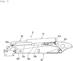
- FIG. 5 is a side view illustrating the bucket cylinder 33a and the cylinder cover 8.
- FIG. 6 is an exploded perspective view of the cylinder cover 8.
- the cylinder cover 8 includes a first cover 81 and a second cover 82.
- the first cover 81 mainly protects a cylinder tube 33b of the bucket cylinder 33a.
- the second cover 82 mainly protects a piston rod 33c of the bucket cylinder 33a.
- Each of the first cover 81 and the second cover 82 has a chevron cross-sectional shape.
- the first cover 81 and the second cover 82 are in slidable contact with each other.
- a guide rail (not illustrated) is provided on an inner surface of the first cover 81 or on an outer surface of the second cover 82. This allows the cylinder cover 8 to expand and contract following expansion and contraction of the bucket cylinder 33a.
- Bolts 811a are fixed to brackets 811 (described later), so that the first cover 81 is attached, via first cover stays 81a, to a portion of the arm 32 closer to the proximal end of the arm 32.
- the first cover stays 81a may be integrated with the first cover 81, or may be separated from the first cover 81.
- the cylinder tube 33b of the bucket cylinder 33a is connected, via a first pin 331, to a pair of arm brackets 321 disposed in the portion of the arm 32 closer to the proximal end of the arm 32.
- the first pin 331 has a pin rotation stopper 331a welded to the periphery of the first pin 331.
- the pin rotation stopper 331a is fixed to the arm brackets 321 by a bolt.
- the first pin 331 protrudes from the pair of arm brackets 321 in a left-and-right direction.
- the first pin 331 has protrusions 331b to which the brackets 811 are rotatably attached via bushes 332.
- the first cover stays 81a are fixed by the bolts 811a.
- Bolts 821a are fixed to brackets 821 (described later), so that the second cover 82 is attached, via second cover stays 82a, to a portion of the arm 32 closer to the distal end of the arm 32.
- the second cover stays 82a may be integrated with the second cover 82, or may be separated from the second cover 82.
- the piston rod 33c of the bucket cylinder 33a is connected, via a second pin 333, to a pair of links 322 disposed in the portion of the arm 32 closer to the distal end of the arm 32.
- the pair of links 322 is disposed in the portion of the arm 32 closer to the distal end of the arm 32. Expansion and contraction of the bucket cylinder 33a causes the links 322 to turn relative to the arm 32, which causes the bucket 33 to turn relative to the arm 32.
- the second pin 333 is fixed to the links 322 via a pin rotation stopper.
- the second pin 333 has both ends to which the brackets 821 are rotatably attached via bushes (not illustrated in FIG. 6 ). To the brackets 821, the second cover stays 82a are fixed by the bolts 821a.
- the cylinder cover 8 is not joined to a cylinder body of the bucket cylinder 33a. Consequently, even in a case where a strong impact is applied to the cylinder cover 8, the impact is not applied to the cylinder body, and thus the bucket cylinder 33a is not broken. This eliminates the need for replacement of the cylinder, which may otherwise be required if the bucket cylinder 33a is broken.
- the cylinder cover 8 has both ends that are rotatably fixed at fulcrums (the first pin 331 and the second pin 333) in the bucket cylinder 33a. Consequently, the cylinder cover 8 entirely covers the bucket cylinder 33a.
- the cylinder cover 8, therefore, can protect not only the cylinder body but also other related members such as a connector, a tube, and a hose.
Landscapes
- Engineering & Computer Science (AREA)
- Mechanical Engineering (AREA)
- Chemical & Material Sciences (AREA)
- Combustion & Propulsion (AREA)
- Transportation (AREA)
- Mining & Mineral Resources (AREA)
- Civil Engineering (AREA)
- General Engineering & Computer Science (AREA)
- Structural Engineering (AREA)
- Component Parts Of Construction Machinery (AREA)
Abstract
Description
- The present invention relates to a structure for attaching a roof guard that protects a ceiling of a cabin of a construction machine.
- Patent Literature 1 (PTL 1) discloses a technique for attaching, above a cab (110), a top guide (150) that protects the cab from an object falling from above. Specifically, according to this technique, bosses (118) protruding from ceiling brackets (116) disposed in an upper portion of the cab are penetrated through holes of top brackets (156) disposed at both ends of the top guide.
- Patent Literature 1: Specification of European Patent No.
1728689 - Unfortunately, since the technique disclosed in the specification of
PTL 1 provides a structure in which the top guide is fixed by the bosses protruding from the upper portion of the cab, a situation as below may occur. That is, if an object falls onto the top guide from above, portions of the top guide and the cab in the vicinity of the bosses may be broken by the impact of the falling object. This may require replacement of not only the top guide but also the cab. - In order to deal with this problem, some aspects of the present invention have an object to provide a structure for attaching a roof guard, the structure being capable of appropriately preventing a cabin from being broken by an object falling from above.
- A structure according to an aspect of the present invention for attaching a roof guard that protects a ceiling of a cabin of a construction machine includes: a first bracket protruding laterally from an outer periphery of an upper end of the cabin; a first protruding piece and a second protruding piece protruding laterally from an outer periphery of the roof guard; and a second bracket horizontally interposed between the first protruding piece and the second protruding piece, the second bracket having a joined part to be joined to an upper end of the first bracket.
- According to the aspect of the present invention, a joined part between the roof guard and the cabin is not on a top surface of the cabin. Consequently, even in a case where the roof guard is broken by an object falling from above, breakage of the cabin can be minimized.
- The aspect of the present invention may be configured such that the second bracket is fixed to the first protruding piece and the second protruding piece.
- The aspect of the present invention may be configured such that the second bracket includes a first support and a second support extending upward from both ends in a horizontal direction of the joined part, and the first support and the second support are respectively fixed to the first protruding piece and the second protruding piece by a pin.
- With such a configuration, an impact force of the falling object can be absorbed by deformation of the second bracket. Consequently, it is possible to suppress or reduce deformation of other parts.
- The aspect of the present invention may be configured such that the first support has a through-hole through which the pin is to be penetrated and below which a first slit is provided, and the second support has a through-hole through which the pin is to be penetrated and below which a second slit is provided.
- In a case where an impact energy of the falling object exceeds a threshold, the impact force can be absorbed by the pin breaking through boundaries between the through-holes and the slits. Furthermore, the impact force that is to be absorbed can be adjusted by distances between the through-holes and the slits.
-
- [
FIG. 1 ] A side view of a construction machine. - [
FIG. 2 ] A plan view of the construction machine. - [
FIG. 3 ] A perspective view of a roof guard. - [
FIG. 4 ] An enlarged perspective view of an attaching part. - [
FIG. 5 ] A side view illustrating a bucket cylinder and a cylinder cover. - [
FIG. 6 ] An exploded perspective view of the cylinder cover. - With reference to the drawings, embodiments of the present invention will be described.
- First, with reference to
FIG. 1 , the following will describe a schematic configuration of anexcavator 1 that is one example of the construction machine. The construction machine is not limited to theexcavator 1, but may be another type of vehicle such as a wheel loader. Theexcavator 1 includes abase carrier 2, awork machine 3, and a revolvingupper body 4. - The
base carrier 2 is driven by a driving force from anengine 42, and causes theexcavator 1 to run. Thebase carrier 2 is provided with a pair of left andright crawlers 21 and a pair of left andright running motors 22. The left and right runningmotors 22, which are hydraulic motors, respectively drive the left andright crawlers 21 to allow theexcavator 1 to move forward or backward. In addition, thebase carrier 2 is provided with ablade 23 and ablade cylinder 24, which is a hydraulic actuator for turning theblade 23 in a top-and-bottom direction. - The
work machine 3 is driven by a driving force from theengine 42, and performs an excavation work on, e.g., earth and sand. Thework machine 3 includes aboom 31, anarm 32, and abucket 33. Thework machine 3 independently drive theboom 31, thearm 32, and thebucket 33 to perform the excavation work. - The
boom 31 has a proximal end supported by a front portion of the revolvingupper body 4, and is turned by aboom cylinder 31a, which is capable of expansion and contraction. Thearm 32 has a proximal end supported by a distal end of theboom 31, and is turned by anarm cylinder 32a, which is capable of expansion and contraction. Thebucket 33 has a proximal end supported by a distal end of thearm 32, and is turned by abucket cylinder 33a, which is capable of expansion and contraction. - The revolving
upper body 4 is configured to be capable of revolving relative to thebase carrier 2 via a revolving bearing (not illustrated). In the revolvingupper body 4, acontrol section 41, theengine 42, a revolvingbase 43, a revolvingmotor 44, and the like are disposed. The revolvingupper body 4 is caused to revolve via the revolving bearing (not illustrated) by a driving force from thedriving motor 44, which is a hydraulic motor. In the revolvingupper body 4, a plurality of hydraulic pumps (not illustrated inFIG. 1 ) driven by theengine 42 is disposed. These hydraulic pumps supply operating oil to theboom cylinder 31a, thearm cylinder 32a, thebucket cylinder 33a, and the like. - In the
control section 41, acontrol seat 411 is disposed. On the left and right of thecontrol seat 411, a pair ofwork operation levers 412 is disposed. In front of thecontrol seat 411, a pair oftraveling levers 413 is disposed. While sitting on thecontrol seat 411, the operator can operate devices such as the work operation levers 412 and the traveling levers 413 to control theengine 42, the hydraulic motors, the hydraulic actuators, and the like to cause theexcavator 1 to run, to make a turn, to perform a work, and/or the like. - The
control seat 411, the work operation levers 412, the traveling levers 413, and the like are disposed on a left portion of the revolvingbase 43, and are covered with acabin 50. Thecabin 50 includes acabin frame 51 and aroof 52. - The
cabin frame 51 is disposed in the left portion of the revolvingbase 43 so that thecabin frame 51 is adjacent to a bonnet disposed in a right portion of the revolvingbase 43. As illustrated inFIG. 2 , thecontrol section 41 is surrounded by a frame, and has a substantially pentagonal shape in a plan view. Thecabin frame 51 is provided with a front glass panel, a rear glass panel, a left panel, a left glass panel, a right panel, a right glass panel, and a door. Theroof 52 is provided above thecabin frame 51. - A
roof guard 60 is attached above thecabin 50, more specifically, above theroof 52. Theroof guard 60 prevents thecabin 50 from being broken by an object falling from above. Theroof guard 60 covers theroof 52, and has a substantially pentagonal shape in a plan view. As illustrated inFIG. 2 , theroof guard 60 may be provided with aright guard 60a protruding rightward for protecting amirror 51a and aright headlamp 51b, which are disposed in a front right portion of thecabin frame 51. In addition, theroof guard 60 may be provided with aleft guard 60b protruding forward for protecting aleft headlamp 51c, which is disposed in a front left portion of thecabin frame 51. Furthermore, theroof guard 60 has a front portion having a plurality ofslits 60c extending in a front-and-rear direction. This allows light collection through a skylight window, if provided, in a front portion of theroof 52. - The
roof guard 60 is attached to thecabin 50 via attachingparts 70. Two attachingparts 70 are disposed in each of the left and right sides. The attachingparts 70 each include afirst bracket 71 on thecabin 50 side, asecond bracket 72 on theroof guard 60 side, apin 73, a first protrudingpiece 74, and a second protrudingpiece 75. - The
first bracket 71 protrudes laterally from the outer periphery of theroof 52. In the present embodiment, twofirst brackets 71 are disposed in each of the left and right sides of theroof 52. Thefirst brackets 71 are welded to theroof 52. Thefirst brackets 71 each have an upper end having a flat surface with a bolt hole. - The
second brackets 72 are each made of an elongated rectangular plate that is bent to have a substantially U-shape in a front view of thesecond bracket 72. Thesecond brackets 72 each include a joinedpart 720 as well as afirst support 721 and asecond support 722. The joinedpart 720 is to be joined to an upper end of a corresponding one of thefirst brackets 71. Thefirst support 721 and thesecond support 722 extend upward from both ends in a horizontal direction of the joinedpart 720. - The joined
part 720 has a center portion having a through-hole. Abolt 723 is inserted through the through-hole, and is tightened to the bolt hole of thefirst bracket 71, so that thesecond bracket 72 is fixed to thefirst bracket 71. - The
first support 721 has an upper end having a through-hole 721a through which thepin 73 is to be penetrated. In addition,first slits 721b are provided below the through-hole 721a of thefirst support 721. The first slits 721b each have a circular arc shape. The plurality offirst slits 721b is arranged in the top-and-bottom direction. - The
second support 722 has a similar shape to that of thefirst support 721. Thesecond support 722 has an upper end having a through-hole (not illustrated inFIG. 3 ) through which thepin 73 is to be penetrated. In addition,second slits 722b are provided below the through-hole of thesecond support 722. The second slits 722b each have a circular arc shape. The plurality ofsecond slits 722b is arranged in the top-and-bottom direction. - The
roof guard 60 has the first protrudingpieces 74 and the second protrudingpieces 75, each of which protrudes laterally from the outer periphery of theroof guard 60. Each of the first protrudingpieces 74 and a corresponding one of the second protrudingpieces 75 are disposed at a space from each other in a horizontal direction. The first protrudingpieces 74 and the second protrudingpieces 75 each have a plate-shape, and are arranged to have thickness directions coinciding with the horizontal direction. The first protrudingpieces 74 and the second protrudingpieces 75 are welded to theroof guard 60. The first protrudingpieces 74 and the second protrudingpieces 75 each have a through-hole through which thepin 73 is to be penetrated. - Each of the
second brackets 72 is horizontally interposed between a corresponding one of the first protrudingpieces 74 and a corresponding one of the second protrudingpieces 75. In other words, thesecond bracket 72 bridges, via itsfirst support 721 and itssecond support 722, between the first protrudingpiece 74 and the second protrudingpiece 75. Thefirst support 721 and thesecond support 722 of thesecond bracket 72 are respectively fixed to the first protrudingpiece 74 and the second protrudingpiece 75 by thepin 73. - According to the present invention, the attaching
parts 70 for theroof guard 60 and thecabin 50 are not disposed on a top surface of thecabin 50. Consequently, even in a case where theroof guard 60 is broken by an object falling from above, breakage of thecabin 50 can be minimized. - Furthermore, an impact force of the falling object can be absorbed by deformation of the joined
parts 720 of thesecond brackets 72. Consequently, it is possible to suppress or reduce deformation of other parts. Moreover, in a case where an impact energy of the falling object exceeds a threshold, the impact force can be absorbed by thepins 73 breaking through boundaries between the through-holes 721a of thefirst supports 721 and their correspondingfirst slits 721b and boundaries between the through-holes of thesecond supports 722 and their correspondingsecond slits 722b. In a case where a greater impact energy is further applied thereto, the impact force can be absorbed by thepins 73 breaking through boundaries between adjacent ones of thefirst slits 721b and boundaries between adjacent ones of thesecond slits 722b. Even in case any of thesecond brackets 72 is deformed or broken, thesecond bracket 72 can be replaced with a new one easily. - The
excavator 1 may include cylinder covers 8 that respectively protect theboom cylinder 31a, thearm cylinder 32a, and thebucket cylinder 33a. The description here deals with thecylinder cover 8 that protects thebucket cylinder 33a. Note that the cylinder covers that protect theboom cylinder 31a and thearm cylinder 32a have similar configurations to that of thecylinder cover 8 that protects thebucket cylinder 33a.FIG. 5 is a side view illustrating thebucket cylinder 33a and thecylinder cover 8.FIG. 6 is an exploded perspective view of thecylinder cover 8. - The
cylinder cover 8 includes afirst cover 81 and asecond cover 82. Thefirst cover 81 mainly protects acylinder tube 33b of thebucket cylinder 33a. Thesecond cover 82 mainly protects apiston rod 33c of thebucket cylinder 33a. Each of thefirst cover 81 and thesecond cover 82 has a chevron cross-sectional shape. - The
first cover 81 and thesecond cover 82 are in slidable contact with each other. A guide rail (not illustrated) is provided on an inner surface of thefirst cover 81 or on an outer surface of thesecond cover 82. This allows thecylinder cover 8 to expand and contract following expansion and contraction of thebucket cylinder 33a. -
Bolts 811a are fixed to brackets 811 (described later), so that thefirst cover 81 is attached, via first cover stays 81a, to a portion of thearm 32 closer to the proximal end of thearm 32. The first cover stays 81a may be integrated with thefirst cover 81, or may be separated from thefirst cover 81. - The
cylinder tube 33b of thebucket cylinder 33a is connected, via afirst pin 331, to a pair ofarm brackets 321 disposed in the portion of thearm 32 closer to the proximal end of thearm 32. Thefirst pin 331 has apin rotation stopper 331a welded to the periphery of thefirst pin 331. Thepin rotation stopper 331a is fixed to thearm brackets 321 by a bolt. - The
first pin 331 protrudes from the pair ofarm brackets 321 in a left-and-right direction. Thefirst pin 331 hasprotrusions 331b to which thebrackets 811 are rotatably attached viabushes 332. To thebrackets 811, the first cover stays 81a are fixed by thebolts 811a. -
Bolts 821a are fixed to brackets 821 (described later), so that thesecond cover 82 is attached, via second cover stays 82a, to a portion of thearm 32 closer to the distal end of thearm 32. The second cover stays 82a may be integrated with thesecond cover 82, or may be separated from thesecond cover 82. - The
piston rod 33c of thebucket cylinder 33a is connected, via asecond pin 333, to a pair oflinks 322 disposed in the portion of thearm 32 closer to the distal end of thearm 32. The pair oflinks 322 is disposed in the portion of thearm 32 closer to the distal end of thearm 32. Expansion and contraction of thebucket cylinder 33a causes thelinks 322 to turn relative to thearm 32, which causes thebucket 33 to turn relative to thearm 32. Thesecond pin 333 is fixed to thelinks 322 via a pin rotation stopper. - The
second pin 333 has both ends to which thebrackets 821 are rotatably attached via bushes (not illustrated inFIG. 6 ). To thebrackets 821, the second cover stays 82a are fixed by thebolts 821a. - As described above, the
cylinder cover 8 is not joined to a cylinder body of thebucket cylinder 33a. Consequently, even in a case where a strong impact is applied to thecylinder cover 8, the impact is not applied to the cylinder body, and thus thebucket cylinder 33a is not broken. This eliminates the need for replacement of the cylinder, which may otherwise be required if thebucket cylinder 33a is broken. - In addition, the
cylinder cover 8 has both ends that are rotatably fixed at fulcrums (thefirst pin 331 and the second pin 333) in thebucket cylinder 33a. Consequently, thecylinder cover 8 entirely covers thebucket cylinder 33a. Thecylinder cover 8, therefore, can protect not only the cylinder body but also other related members such as a connector, a tube, and a hose. - Some embodiments of the present invention have been described with reference to the drawings. It however should be considered that specific configurations of the present invention are not limited to these embodiments. The scope of the present invention is indicated not only by the description of the above embodiments but also by the scope of the claims, and includes all variations and modifications that have been made within a meaning and a scope equivalent to those of the scope of the claims.
-
- 1
- excavator
- 2
- base carrier
- 3
- work machine
- 4
- revolving upper body
- 50
- cabin
- 52
- roof
- 60
- roof guard
- 70
- attaching part
- 71
- first bracket
- 72
- second bracket
- 720
- joined part
- 721
- first support
- 721a
- through-hole
- 721b
- first slit
- 722
- second support
- 722b
- second slit
- 73
- pin
- 74
- first protruding piece
- 75
- second protruding piece
- 8
- cylinder cover
Claims (4)
- A structure for attaching a roof guard that protects a ceiling of a cabin of a construction machine, comprising:a first bracket protruding laterally from an outer periphery of an upper end of the cabin;a first protruding piece and a second protruding piece protruding laterally from an outer periphery of the roof guard; anda second bracket horizontally interposed between the first protruding piece and the second protruding piece, the second bracket having a joined part to be joined to an upper end of the first bracket.
- The structure according to claim 1, wherein the second bracket is fixed to the first protruding piece and the second protruding piece.
- The structure according to claim 1 or 2, whereinthe second bracket includes a first support and a second support extending upward from both ends in a horizontal direction of the joined part, andthe first support and the second support are respectively fixed to the first protruding piece and the second protruding piece by a pin.
- The structure according to claim 3, whereinthe first support has a through-hole through which the pin is to be penetrated and below which a first slit is provided, andthe second support has a through-hole through which the pin is to be penetrated and below which a second slit is provided.
Priority Applications (1)
| Application Number | Priority Date | Filing Date | Title |
|---|---|---|---|
| EP18305477.4A EP3556613B1 (en) | 2018-04-18 | 2018-04-18 | Structure for attaching roof guard fro construction machine |
Applications Claiming Priority (1)
| Application Number | Priority Date | Filing Date | Title |
|---|---|---|---|
| EP18305477.4A EP3556613B1 (en) | 2018-04-18 | 2018-04-18 | Structure for attaching roof guard fro construction machine |
Publications (2)
| Publication Number | Publication Date |
|---|---|
| EP3556613A1 true EP3556613A1 (en) | 2019-10-23 |
| EP3556613B1 EP3556613B1 (en) | 2021-03-10 |
Family
ID=62567561
Family Applications (1)
| Application Number | Title | Priority Date | Filing Date |
|---|---|---|---|
| EP18305477.4A Not-in-force EP3556613B1 (en) | 2018-04-18 | 2018-04-18 | Structure for attaching roof guard fro construction machine |
Country Status (1)
| Country | Link |
|---|---|
| EP (1) | EP3556613B1 (en) |
Cited By (1)
| Publication number | Priority date | Publication date | Assignee | Title |
|---|---|---|---|---|
| CN113500901A (en) * | 2021-06-25 | 2021-10-15 | 三一重机有限公司 | Cab and working machine |
Citations (3)
| Publication number | Priority date | Publication date | Assignee | Title |
|---|---|---|---|---|
| US3731967A (en) * | 1971-08-25 | 1973-05-08 | Sealed Unit Services Inc | Roof walkway for truck cabs |
| EP1728689A1 (en) | 2005-06-01 | 2006-12-06 | Volvo Construction Equipment Holding Sweden AB | Operator protective structure installed on cabin of construction machine |
| KR20150057609A (en) * | 2013-11-20 | 2015-05-28 | 현대자동차주식회사 | Structure for mounting hinge of tail gate in vehicle |
-
2018
- 2018-04-18 EP EP18305477.4A patent/EP3556613B1/en not_active Not-in-force
Patent Citations (3)
| Publication number | Priority date | Publication date | Assignee | Title |
|---|---|---|---|---|
| US3731967A (en) * | 1971-08-25 | 1973-05-08 | Sealed Unit Services Inc | Roof walkway for truck cabs |
| EP1728689A1 (en) | 2005-06-01 | 2006-12-06 | Volvo Construction Equipment Holding Sweden AB | Operator protective structure installed on cabin of construction machine |
| KR20150057609A (en) * | 2013-11-20 | 2015-05-28 | 현대자동차주식회사 | Structure for mounting hinge of tail gate in vehicle |
Cited By (2)
| Publication number | Priority date | Publication date | Assignee | Title |
|---|---|---|---|---|
| CN113500901A (en) * | 2021-06-25 | 2021-10-15 | 三一重机有限公司 | Cab and working machine |
| CN113500901B (en) * | 2021-06-25 | 2023-03-14 | 三一重机有限公司 | Cab and Work Machinery |
Also Published As
| Publication number | Publication date |
|---|---|
| EP3556613B1 (en) | 2021-03-10 |
Similar Documents
| Publication | Publication Date | Title |
|---|---|---|
| ES2258965T3 (en) | MINI CHARGER WITH CAB. | |
| RU2516673C2 (en) | Working machine | |
| EP1748113B1 (en) | Construction machine with an upper frame structure for supporting the cabin | |
| JP5009933B2 (en) | Wheel loader | |
| JP5204911B1 (en) | Bulldozer | |
| CN101548048A (en) | Wheel loader | |
| EP3556613B1 (en) | Structure for attaching roof guard fro construction machine | |
| CN111601932B (en) | Cabs for work machines and work machines | |
| US10583866B2 (en) | Work vehicle | |
| US11479944B2 (en) | Work machine and cab | |
| EP4194616B1 (en) | Cab support structure and construction machine | |
| JP2001173017A (en) | Construction machinery | |
| CN108138466B (en) | The driver's cabin and working truck of working truck | |
| EP3396072A1 (en) | Compact construction machine | |
| US12129630B2 (en) | Installation structure of electric component and hydraulic hose for working machine | |
| EP2857597A1 (en) | Construction machine | |
| EP2423393A1 (en) | Cab protection structure for construction machinery | |
| EP4733489A1 (en) | Cab for construction machine | |
| JP2017214033A (en) | Working machine | |
| CN114250813A (en) | Working device of skid steer loader and skid steer loader | |
| EP1717378B1 (en) | An earth moving machine | |
| KR20210095134A (en) | Power machine with bracket mount for engine with pump package | |
| US12618225B1 (en) | Working vehicle | |
| KR102872866B1 (en) | work machine | |
| JP2005188219A (en) | Construction machinery door equipment |
Legal Events
| Date | Code | Title | Description |
|---|---|---|---|
| PUAI | Public reference made under article 153(3) epc to a published international application that has entered the european phase |
Free format text: ORIGINAL CODE: 0009012 |
|
| STAA | Information on the status of an ep patent application or granted ep patent |
Free format text: STATUS: THE APPLICATION HAS BEEN PUBLISHED |
|
| AK | Designated contracting states |
Kind code of ref document: A1 Designated state(s): AL AT BE BG CH CY CZ DE DK EE ES FI FR GB GR HR HU IE IS IT LI LT LU LV MC MK MT NL NO PL PT RO RS SE SI SK SM TR |
|
| AX | Request for extension of the european patent |
Extension state: BA ME |
|
| STAA | Information on the status of an ep patent application or granted ep patent |
Free format text: STATUS: REQUEST FOR EXAMINATION WAS MADE |
|
| 17P | Request for examination filed |
Effective date: 20200424 |
|
| RBV | Designated contracting states (corrected) |
Designated state(s): AL AT BE BG CH CY CZ DE DK EE ES FI FR GB GR HR HU IE IS IT LI LT LU LV MC MK MT NL NO PL PT RO RS SE SI SK SM TR |
|
| RAP1 | Party data changed (applicant data changed or rights of an application transferred) |
Owner name: YANMAR POWER TECHNOLOGY CO., LTD. |
|
| GRAP | Despatch of communication of intention to grant a patent |
Free format text: ORIGINAL CODE: EPIDOSNIGR1 |
|
| STAA | Information on the status of an ep patent application or granted ep patent |
Free format text: STATUS: GRANT OF PATENT IS INTENDED |
|
| INTG | Intention to grant announced |
Effective date: 20201102 |
|
| GRAS | Grant fee paid |
Free format text: ORIGINAL CODE: EPIDOSNIGR3 |
|
| GRAA | (expected) grant |
Free format text: ORIGINAL CODE: 0009210 |
|
| STAA | Information on the status of an ep patent application or granted ep patent |
Free format text: STATUS: THE PATENT HAS BEEN GRANTED |
|
| AK | Designated contracting states |
Kind code of ref document: B1 Designated state(s): AL AT BE BG CH CY CZ DE DK EE ES FI FR GB GR HR HU IE IS IT LI LT LU LV MC MK MT NL NO PL PT RO RS SE SI SK SM TR |
|
| REG | Reference to a national code |
Ref country code: GB Ref legal event code: FG4D |
|
| REG | Reference to a national code |
Ref country code: AT Ref legal event code: REF Ref document number: 1369484 Country of ref document: AT Kind code of ref document: T Effective date: 20210315 Ref country code: CH Ref legal event code: EP |
|
| REG | Reference to a national code |
Ref country code: IE Ref legal event code: FG4D |
|
| REG | Reference to a national code |
Ref country code: DE Ref legal event code: R096 Ref document number: 602018013695 Country of ref document: DE |
|
| REG | Reference to a national code |
Ref country code: LT Ref legal event code: MG9D |
|
| PG25 | Lapsed in a contracting state [announced via postgrant information from national office to epo] |
Ref country code: GR Free format text: LAPSE BECAUSE OF FAILURE TO SUBMIT A TRANSLATION OF THE DESCRIPTION OR TO PAY THE FEE WITHIN THE PRESCRIBED TIME-LIMIT Effective date: 20210611 Ref country code: FI Free format text: LAPSE BECAUSE OF FAILURE TO SUBMIT A TRANSLATION OF THE DESCRIPTION OR TO PAY THE FEE WITHIN THE PRESCRIBED TIME-LIMIT Effective date: 20210310 Ref country code: HR Free format text: LAPSE BECAUSE OF FAILURE TO SUBMIT A TRANSLATION OF THE DESCRIPTION OR TO PAY THE FEE WITHIN THE PRESCRIBED TIME-LIMIT Effective date: 20210310 Ref country code: BG Free format text: LAPSE BECAUSE OF FAILURE TO SUBMIT A TRANSLATION OF THE DESCRIPTION OR TO PAY THE FEE WITHIN THE PRESCRIBED TIME-LIMIT Effective date: 20210610 Ref country code: LT Free format text: LAPSE BECAUSE OF FAILURE TO SUBMIT A TRANSLATION OF THE DESCRIPTION OR TO PAY THE FEE WITHIN THE PRESCRIBED TIME-LIMIT Effective date: 20210310 Ref country code: NO Free format text: LAPSE BECAUSE OF FAILURE TO SUBMIT A TRANSLATION OF THE DESCRIPTION OR TO PAY THE FEE WITHIN THE PRESCRIBED TIME-LIMIT Effective date: 20210610 |
|
| REG | Reference to a national code |
Ref country code: AT Ref legal event code: MK05 Ref document number: 1369484 Country of ref document: AT Kind code of ref document: T Effective date: 20210310 |
|
| REG | Reference to a national code |
Ref country code: NL Ref legal event code: MP Effective date: 20210310 |
|
| PG25 | Lapsed in a contracting state [announced via postgrant information from national office to epo] |
Ref country code: SE Free format text: LAPSE BECAUSE OF FAILURE TO SUBMIT A TRANSLATION OF THE DESCRIPTION OR TO PAY THE FEE WITHIN THE PRESCRIBED TIME-LIMIT Effective date: 20210310 Ref country code: RS Free format text: LAPSE BECAUSE OF FAILURE TO SUBMIT A TRANSLATION OF THE DESCRIPTION OR TO PAY THE FEE WITHIN THE PRESCRIBED TIME-LIMIT Effective date: 20210310 Ref country code: LV Free format text: LAPSE BECAUSE OF FAILURE TO SUBMIT A TRANSLATION OF THE DESCRIPTION OR TO PAY THE FEE WITHIN THE PRESCRIBED TIME-LIMIT Effective date: 20210310 |
|
| PG25 | Lapsed in a contracting state [announced via postgrant information from national office to epo] |
Ref country code: NL Free format text: LAPSE BECAUSE OF FAILURE TO SUBMIT A TRANSLATION OF THE DESCRIPTION OR TO PAY THE FEE WITHIN THE PRESCRIBED TIME-LIMIT Effective date: 20210310 |
|
| PG25 | Lapsed in a contracting state [announced via postgrant information from national office to epo] |
Ref country code: AT Free format text: LAPSE BECAUSE OF FAILURE TO SUBMIT A TRANSLATION OF THE DESCRIPTION OR TO PAY THE FEE WITHIN THE PRESCRIBED TIME-LIMIT Effective date: 20210310 Ref country code: SM Free format text: LAPSE BECAUSE OF FAILURE TO SUBMIT A TRANSLATION OF THE DESCRIPTION OR TO PAY THE FEE WITHIN THE PRESCRIBED TIME-LIMIT Effective date: 20210310 Ref country code: EE Free format text: LAPSE BECAUSE OF FAILURE TO SUBMIT A TRANSLATION OF THE DESCRIPTION OR TO PAY THE FEE WITHIN THE PRESCRIBED TIME-LIMIT Effective date: 20210310 Ref country code: CZ Free format text: LAPSE BECAUSE OF FAILURE TO SUBMIT A TRANSLATION OF THE DESCRIPTION OR TO PAY THE FEE WITHIN THE PRESCRIBED TIME-LIMIT Effective date: 20210310 |
|
| PG25 | Lapsed in a contracting state [announced via postgrant information from national office to epo] |
Ref country code: IS Free format text: LAPSE BECAUSE OF FAILURE TO SUBMIT A TRANSLATION OF THE DESCRIPTION OR TO PAY THE FEE WITHIN THE PRESCRIBED TIME-LIMIT Effective date: 20210710 Ref country code: RO Free format text: LAPSE BECAUSE OF FAILURE TO SUBMIT A TRANSLATION OF THE DESCRIPTION OR TO PAY THE FEE WITHIN THE PRESCRIBED TIME-LIMIT Effective date: 20210310 Ref country code: SK Free format text: LAPSE BECAUSE OF FAILURE TO SUBMIT A TRANSLATION OF THE DESCRIPTION OR TO PAY THE FEE WITHIN THE PRESCRIBED TIME-LIMIT Effective date: 20210310 Ref country code: PT Free format text: LAPSE BECAUSE OF FAILURE TO SUBMIT A TRANSLATION OF THE DESCRIPTION OR TO PAY THE FEE WITHIN THE PRESCRIBED TIME-LIMIT Effective date: 20210712 Ref country code: PL Free format text: LAPSE BECAUSE OF FAILURE TO SUBMIT A TRANSLATION OF THE DESCRIPTION OR TO PAY THE FEE WITHIN THE PRESCRIBED TIME-LIMIT Effective date: 20210310 |
|
| REG | Reference to a national code |
Ref country code: DE Ref legal event code: R097 Ref document number: 602018013695 Country of ref document: DE |
|
| PG25 | Lapsed in a contracting state [announced via postgrant information from national office to epo] |
Ref country code: LU Free format text: LAPSE BECAUSE OF NON-PAYMENT OF DUE FEES Effective date: 20210418 |
|
| PLBE | No opposition filed within time limit |
Free format text: ORIGINAL CODE: 0009261 |
|
| STAA | Information on the status of an ep patent application or granted ep patent |
Free format text: STATUS: NO OPPOSITION FILED WITHIN TIME LIMIT |
|
| PG25 | Lapsed in a contracting state [announced via postgrant information from national office to epo] |
Ref country code: CH Free format text: LAPSE BECAUSE OF NON-PAYMENT OF DUE FEES Effective date: 20210430 Ref country code: DK Free format text: LAPSE BECAUSE OF FAILURE TO SUBMIT A TRANSLATION OF THE DESCRIPTION OR TO PAY THE FEE WITHIN THE PRESCRIBED TIME-LIMIT Effective date: 20210310 Ref country code: AL Free format text: LAPSE BECAUSE OF FAILURE TO SUBMIT A TRANSLATION OF THE DESCRIPTION OR TO PAY THE FEE WITHIN THE PRESCRIBED TIME-LIMIT Effective date: 20210310 Ref country code: MC Free format text: LAPSE BECAUSE OF FAILURE TO SUBMIT A TRANSLATION OF THE DESCRIPTION OR TO PAY THE FEE WITHIN THE PRESCRIBED TIME-LIMIT Effective date: 20210310 Ref country code: LI Free format text: LAPSE BECAUSE OF NON-PAYMENT OF DUE FEES Effective date: 20210430 Ref country code: ES Free format text: LAPSE BECAUSE OF FAILURE TO SUBMIT A TRANSLATION OF THE DESCRIPTION OR TO PAY THE FEE WITHIN THE PRESCRIBED TIME-LIMIT Effective date: 20210310 |
|
| 26N | No opposition filed |
Effective date: 20211213 |
|
| PG25 | Lapsed in a contracting state [announced via postgrant information from national office to epo] |
Ref country code: SI Free format text: LAPSE BECAUSE OF FAILURE TO SUBMIT A TRANSLATION OF THE DESCRIPTION OR TO PAY THE FEE WITHIN THE PRESCRIBED TIME-LIMIT Effective date: 20210310 |
|
| PG25 | Lapsed in a contracting state [announced via postgrant information from national office to epo] |
Ref country code: IT Free format text: LAPSE BECAUSE OF FAILURE TO SUBMIT A TRANSLATION OF THE DESCRIPTION OR TO PAY THE FEE WITHIN THE PRESCRIBED TIME-LIMIT Effective date: 20210310 Ref country code: IE Free format text: LAPSE BECAUSE OF NON-PAYMENT OF DUE FEES Effective date: 20210418 |
|
| PG25 | Lapsed in a contracting state [announced via postgrant information from national office to epo] |
Ref country code: IS Free format text: LAPSE BECAUSE OF FAILURE TO SUBMIT A TRANSLATION OF THE DESCRIPTION OR TO PAY THE FEE WITHIN THE PRESCRIBED TIME-LIMIT Effective date: 20210710 |
|
| PG25 | Lapsed in a contracting state [announced via postgrant information from national office to epo] |
Ref country code: CY Free format text: LAPSE BECAUSE OF FAILURE TO SUBMIT A TRANSLATION OF THE DESCRIPTION OR TO PAY THE FEE WITHIN THE PRESCRIBED TIME-LIMIT Effective date: 20210310 |
|
| PG25 | Lapsed in a contracting state [announced via postgrant information from national office to epo] |
Ref country code: HU Free format text: LAPSE BECAUSE OF FAILURE TO SUBMIT A TRANSLATION OF THE DESCRIPTION OR TO PAY THE FEE WITHIN THE PRESCRIBED TIME-LIMIT; INVALID AB INITIO Effective date: 20180418 |
|
| PGFP | Annual fee paid to national office [announced via postgrant information from national office to epo] |
Ref country code: FR Payment date: 20230424 Year of fee payment: 6 Ref country code: DE Payment date: 20230420 Year of fee payment: 6 |
|
| PGFP | Annual fee paid to national office [announced via postgrant information from national office to epo] |
Ref country code: BE Payment date: 20230419 Year of fee payment: 6 |
|
| PGFP | Annual fee paid to national office [announced via postgrant information from national office to epo] |
Ref country code: GB Payment date: 20230419 Year of fee payment: 6 |
|
| PG25 | Lapsed in a contracting state [announced via postgrant information from national office to epo] |
Ref country code: MK Free format text: LAPSE BECAUSE OF FAILURE TO SUBMIT A TRANSLATION OF THE DESCRIPTION OR TO PAY THE FEE WITHIN THE PRESCRIBED TIME-LIMIT Effective date: 20210310 |
|
| PG25 | Lapsed in a contracting state [announced via postgrant information from national office to epo] |
Ref country code: TR Free format text: LAPSE BECAUSE OF FAILURE TO SUBMIT A TRANSLATION OF THE DESCRIPTION OR TO PAY THE FEE WITHIN THE PRESCRIBED TIME-LIMIT Effective date: 20210310 |
|
| PG25 | Lapsed in a contracting state [announced via postgrant information from national office to epo] |
Ref country code: MT Free format text: LAPSE BECAUSE OF FAILURE TO SUBMIT A TRANSLATION OF THE DESCRIPTION OR TO PAY THE FEE WITHIN THE PRESCRIBED TIME-LIMIT Effective date: 20210310 |
|
| REG | Reference to a national code |
Ref country code: DE Ref legal event code: R119 Ref document number: 602018013695 Country of ref document: DE |
|
| GBPC | Gb: european patent ceased through non-payment of renewal fee |
Effective date: 20240418 |
|
| REG | Reference to a national code |
Ref country code: BE Ref legal event code: MM Effective date: 20240430 |
|
| PG25 | Lapsed in a contracting state [announced via postgrant information from national office to epo] |
Ref country code: DE Free format text: LAPSE BECAUSE OF NON-PAYMENT OF DUE FEES Effective date: 20241105 |
|
| PG25 | Lapsed in a contracting state [announced via postgrant information from national office to epo] |
Ref country code: BE Free format text: LAPSE BECAUSE OF NON-PAYMENT OF DUE FEES Effective date: 20240430 |
|
| PG25 | Lapsed in a contracting state [announced via postgrant information from national office to epo] |
Ref country code: GB Free format text: LAPSE BECAUSE OF NON-PAYMENT OF DUE FEES Effective date: 20240418 |
|
| PG25 | Lapsed in a contracting state [announced via postgrant information from national office to epo] |
Ref country code: FR Free format text: LAPSE BECAUSE OF NON-PAYMENT OF DUE FEES Effective date: 20240430 |
|
| PG25 | Lapsed in a contracting state [announced via postgrant information from national office to epo] |
Ref country code: GB Free format text: LAPSE BECAUSE OF NON-PAYMENT OF DUE FEES Effective date: 20240418 Ref country code: FR Free format text: LAPSE BECAUSE OF NON-PAYMENT OF DUE FEES Effective date: 20240430 Ref country code: DE Free format text: LAPSE BECAUSE OF NON-PAYMENT OF DUE FEES Effective date: 20241105 Ref country code: BE Free format text: LAPSE BECAUSE OF NON-PAYMENT OF DUE FEES Effective date: 20240430 |