EP3556575B1 - Tyre - Google Patents
Tyre Download PDFInfo
- Publication number
- EP3556575B1 EP3556575B1 EP19165134.8A EP19165134A EP3556575B1 EP 3556575 B1 EP3556575 B1 EP 3556575B1 EP 19165134 A EP19165134 A EP 19165134A EP 3556575 B1 EP3556575 B1 EP 3556575B1
- Authority
- EP
- European Patent Office
- Prior art keywords
- tyre
- groove
- radial direction
- minimum
- opening
- Prior art date
- Legal status (The legal status is an assumption and is not a legal conclusion. Google has not performed a legal analysis and makes no representation as to the accuracy of the status listed.)
- Active
Links
Images


Classifications
-
- B—PERFORMING OPERATIONS; TRANSPORTING
- B60—VEHICLES IN GENERAL
- B60C—VEHICLE TYRES; TYRE INFLATION; TYRE CHANGING; CONNECTING VALVES TO INFLATABLE ELASTIC BODIES IN GENERAL; DEVICES OR ARRANGEMENTS RELATED TO TYRES
- B60C11/00—Tyre tread bands; Tread patterns; Anti-skid inserts
- B60C11/03—Tread patterns
- B60C11/04—Tread patterns in which the raised area of the pattern consists only of continuous circumferential ribs, e.g. zig-zag
- B60C11/042—Tread patterns in which the raised area of the pattern consists only of continuous circumferential ribs, e.g. zig-zag further characterised by the groove cross-section
-
- B—PERFORMING OPERATIONS; TRANSPORTING
- B60—VEHICLES IN GENERAL
- B60C—VEHICLE TYRES; TYRE INFLATION; TYRE CHANGING; CONNECTING VALVES TO INFLATABLE ELASTIC BODIES IN GENERAL; DEVICES OR ARRANGEMENTS RELATED TO TYRES
- B60C11/00—Tyre tread bands; Tread patterns; Anti-skid inserts
- B60C11/03—Tread patterns
- B60C11/13—Tread patterns characterised by the groove cross-section, e.g. for buttressing or preventing stone-trapping
-
- B—PERFORMING OPERATIONS; TRANSPORTING
- B60—VEHICLES IN GENERAL
- B60C—VEHICLE TYRES; TYRE INFLATION; TYRE CHANGING; CONNECTING VALVES TO INFLATABLE ELASTIC BODIES IN GENERAL; DEVICES OR ARRANGEMENTS RELATED TO TYRES
- B60C11/00—Tyre tread bands; Tread patterns; Anti-skid inserts
- B60C11/03—Tread patterns
- B60C11/12—Tread patterns characterised by the use of narrow slits or incisions, e.g. sipes
- B60C11/1272—Width of the sipe
- B60C11/1281—Width of the sipe different within the same sipe, i.e. enlarged width portion at sipe bottom or along its length
-
- B—PERFORMING OPERATIONS; TRANSPORTING
- B60—VEHICLES IN GENERAL
- B60C—VEHICLE TYRES; TYRE INFLATION; TYRE CHANGING; CONNECTING VALVES TO INFLATABLE ELASTIC BODIES IN GENERAL; DEVICES OR ARRANGEMENTS RELATED TO TYRES
- B60C11/00—Tyre tread bands; Tread patterns; Anti-skid inserts
- B60C11/03—Tread patterns
- B60C11/13—Tread patterns characterised by the groove cross-section, e.g. for buttressing or preventing stone-trapping
- B60C11/1307—Tread patterns characterised by the groove cross-section, e.g. for buttressing or preventing stone-trapping with special features of the groove walls
- B60C11/1315—Tread patterns characterised by the groove cross-section, e.g. for buttressing or preventing stone-trapping with special features of the groove walls having variable inclination angles, e.g. warped groove walls
-
- B—PERFORMING OPERATIONS; TRANSPORTING
- B60—VEHICLES IN GENERAL
- B60C—VEHICLE TYRES; TYRE INFLATION; TYRE CHANGING; CONNECTING VALVES TO INFLATABLE ELASTIC BODIES IN GENERAL; DEVICES OR ARRANGEMENTS RELATED TO TYRES
- B60C11/00—Tyre tread bands; Tread patterns; Anti-skid inserts
- B60C11/03—Tread patterns
- B60C2011/0337—Tread patterns characterised by particular design features of the pattern
- B60C2011/0339—Grooves
- B60C2011/0358—Lateral grooves, i.e. having an angle of 45 to 90 degees to the equatorial plane
- B60C2011/0365—Lateral grooves, i.e. having an angle of 45 to 90 degees to the equatorial plane characterised by width
-
- B—PERFORMING OPERATIONS; TRANSPORTING
- B60—VEHICLES IN GENERAL
- B60C—VEHICLE TYRES; TYRE INFLATION; TYRE CHANGING; CONNECTING VALVES TO INFLATABLE ELASTIC BODIES IN GENERAL; DEVICES OR ARRANGEMENTS RELATED TO TYRES
- B60C11/00—Tyre tread bands; Tread patterns; Anti-skid inserts
- B60C11/03—Tread patterns
- B60C2011/0337—Tread patterns characterised by particular design features of the pattern
- B60C2011/0339—Grooves
- B60C2011/0358—Lateral grooves, i.e. having an angle of 45 to 90 degees to the equatorial plane
- B60C2011/0367—Lateral grooves, i.e. having an angle of 45 to 90 degees to the equatorial plane characterised by depth
-
- B—PERFORMING OPERATIONS; TRANSPORTING
- B60—VEHICLES IN GENERAL
- B60C—VEHICLE TYRES; TYRE INFLATION; TYRE CHANGING; CONNECTING VALVES TO INFLATABLE ELASTIC BODIES IN GENERAL; DEVICES OR ARRANGEMENTS RELATED TO TYRES
- B60C11/00—Tyre tread bands; Tread patterns; Anti-skid inserts
- B60C11/03—Tread patterns
- B60C11/13—Tread patterns characterised by the groove cross-section, e.g. for buttressing or preventing stone-trapping
- B60C11/1307—Tread patterns characterised by the groove cross-section, e.g. for buttressing or preventing stone-trapping with special features of the groove walls
- B60C2011/1338—Tread patterns characterised by the groove cross-section, e.g. for buttressing or preventing stone-trapping with special features of the groove walls comprising protrusions
Definitions
- the present disclosure relates to tyres, more particularly to a tyre capable of improving uneven wear resistance and grip performance in a well-balanced manner.
- Patent document 1 discloses a tyre tread provided with lateral cuts which include first part and ducts located radially inside the first parts in order to improve performance when the tread has worn down.
- Patent document 1 Japanese Unexamined Patent Application Publication 2017-509531
- Document WO 2017/072139 A1 discloses a tyre according to the preamble of claim 1. Furthermore, tyres showing the features of the preamble of claim 1 except the feature that a minimum distance in the tyre radial direction between the minimum portion and the opening is smaller than a minimum distance in the tyre radial direction between the minimum portion and the maximum portion are known from documents JP H10 264613 A , WO 2013/087440 A1 , JP 2003 159911 A1 , WO 2017/090332 A1 , EP 2 900 489 A1 , and GB 2 329 161 A .
- the present disclosure has been made in view of the above circumstances and has a major object to provide tyres capable of improving uneven wear resistance and grip performance in a well-balanced manner.
- the inventive tyre has the features of claim 1.
- a tyre includes a tread portion having a tread surface provided with grooves extending in a tyre axial direction.
- Each groove includes an opening formed on the tread surface, a minimum portion located inwardly in a tyre radial direction of the opening and having a groove width being locally minimum, and a maximum portion located inwardly in the tyre radial direction of the minimum portion and having a groove width being locally maximum in a region inwardly in the tyre radial direction of the opening.
- each groove may include a groove bottom portion located innermost in the tyre radial direction, and a minimum distance in the tyre radial direction between the minimum portion and the maximum portion may be greater than a minimum distance in the tyre radial direction between the maximum portion and the groove bottom portion.
- a groove width of the opening may be greater than the groove width of the maximum portion.
- a minimum distance in the tyre radial direction between the minimum portion and the opening is smaller than a minimum distance in the tyre radial direction between the minimum portion and the maximum portion.
- a minimum distance in the tyre radial direction between the minimum portion and the opening may be smaller than a minimum distance in the tyre radial direction between the maximum portion and a groove bottom portion.
- a minimum distance in the tyre radial direction between the minimum portion and the opening may be equal to or less than 40% of a minimum distance in the tyre radial direction between the opening and a groove bottom portion.
- each groove may include a groove bottom portion located innermost in the tyre radial direction, and the groove bottom portion is located on a center of a curved surface curved protruding inwardly in the tyre radial direction.
- a region from the opening to the minimum portion of each groove is formed by a pair of inclined surfaces inclined with respect to the tyre radial direction.
- the pair of inclined surfaces each may be one or more planes.
- the pair of the inclined surfaces may be a curved surface.
- the pair of inclined surfaces may include one or more planes and a curved surface.
- each groove may be a lateral groove in communication with a tread edge of the tread portion.
- FIG. 1 illustrates a side view of a tyre 1 according to an embodiment.
- the tyre 1 according to the present disclosure can be used for various kinds of tyres, e.g., pneumatic tyres for passenger car and heavy-duty vehicle, and non-pneumatic tyres that can support the tyre load by structural members without being inflated with a pressurized air.
- the tyre 1 according to the embodiment includes a tread portion 2 having a tread surface 2a provided with grooves 3 extending in the tyre axial direction.
- FIG. 2 is a cross-sectional view of one groove 3.
- each groove 3 includes an opening 4 formed on the tread surface 2a, a minimum portion 5 located inwardly in the tyre radial direction of the opening 4, and a maximum portion 6 located inwardly in the tyre radial direction of the minimum portion 5.
- the minimum portion 5 is a portion having a groove width W1 which is locally minimum.
- the maximum portion 6 is a portion having a groove width W2 which is locally maximum in a region inwardly in the tyre radial direction of the opening 4.
- dimensions of respective portions of the tyre 1 are values measured under a normal state unless otherwise noted.
- the normal state is such that the tyre 1, when the tyre 1 is a pneumatic tyre, is mounted on a standard wheel rim with a standard pressure but is loaded with no tyre load.
- the standard wheel rim is a wheel rim officially approved for each tyre by standards organizations on which the tyre 1 is based, wherein the standard wheel rim is the "standard rim” specified in JATMA, the "Design Rim” in TRA, and the “Measuring Rim” in ETRTO, for example.
- the standard pressure is a standard pressure officially approved for each tyre by standards organizations on which the tyre is based, wherein the standard pressure is the "maximum air pressure" in JATMA, the maximum pressure given in the "Tire Load Limits at Various Cold Inflation Pressures” table in TRA, and the “Inflation Pressure” in ETRTO, for example.
- FIG. 3 illustrates a cross-sectional view of the groove 3 upon grounding.
- the groove 3 can moderate braking load by a region between the opening 4 and the minimum portion 5, improving uneven wear resistance of the tyre 1.
- the minimum portion 5, due to braking load approaches the ground and then comes into contact with it, and thus a ground contact area of the tyre 1 increases so as to improve grip performance.
- the maximum portion 6, due to its large cross-sectional area, can maintain flexibility thereof appropriately, improving uneven wear resistance of the tyre 1 further.
- each groove 3 includes a groove bottom portion 7 located innermost thereof in the tyre radial direction. It is preferable that the minimum distance L1 in the tyre radial direction between the minimum portion 5 and the maximum portion 6 is greater than the minimum distance L2 in the tyre radial direction between the maximum portion 6 and the groove bottom portion 7. In such a tyre 1, since the maximum portion 6 is located inwardly in the tyre radial direction of the center location of a region between the minimum portion 5 and the groove bottom portion 7, reduction in stiffness due to the maximum portion 6 can be suppressed, and thus grip performance of the tyre 1 can be improved.
- the minimum distance L3 in the tyre radial direction between the minimum portion 5 and the opening 4 is smaller than the minimum distance L1 in the tyre radial direction between the minimum portion 5 and the maximum portion 6. Further, it is preferable that the minimum distance L3 in the tyre radial direction between the minimum portion 5 and the opening 4 is smaller than the minimum distance L2 in the tyre radial direction between the maximum portion 6 and the groove bottom portion 7.
- Such a groove 3 can maintain stiffness of the tyre 1 within a proper range, improving uneven wear resistance and grip performance in a high level.
- the minimum distance L3 in the tyre radial direction between the minimum portion 5 and the opening 4 is equal to or less than 40% of the minimum distance L4 in the tyre radial direction between the opening 4 and the groove bottom portion 7.
- the minimum distance L4 between the opening 4 and the groove bottom portion 7 corresponds to a groove depth of the groove 3.
- a groove width W3 of the opening 4 is greater than the groove width W2 of the maximum portion 6.
- Such an opening 4 can increase the groove width difference between the minimum portion 5 and the opening 4 while maintaining the minimum distance L3 between the minimum portion 5 and the opening 4.
- the groove 3 can disperse braking load, improving uneven wear resistance of the tyre 1.
- a region from the opening 4 to the minimum portion 5 of each groove 3 is formed by a pair of inclined surfaces 8 inclined with respect to the tyre radial direction.
- the pair of inclined surfaces 8 each consists of a single plane 8a.
- Such an inclined surface 8 can come into contact with the ground appropriately (shown in FIG. 3 ) by receiving braking load, resulting in increase of a ground contact area of the tyre 1 so that grip performance of the tyre 1 is improved.
- the plane 8a of each inclined surface 8 has an angle ⁇ 1 of from 5 to 30 degrees with respect to the tread surface 2a.
- the angles ⁇ 1 of the inclined surface 8 is less than 5 degrees, braking load tends to act on the minimum portion 5 locally, and there is a risk that uneven wear resistance of the tyre 1 does not improve.
- the angle ⁇ 1 of the inclined surface 8 is more than 30 degrees, braking load tends to act on the opening 4 locally, and there is a risk that uneven wear resistance of the tyre 1 does not improve.
- a region from the minimum portion 5 to the maximum portion 6 of each groove 3 is formed by a pair of internal inclined surfaces 9 inclined with respect to the tyre radial direction.
- the pair of internal inclined surfaces 9 includes a plane 9a and a curved surface 9b.
- the plane 9a of each internal inclined surface 9 is inclined at an angle ⁇ 2 of from 5 to 25 degrees with respect to the tyre radial direction.
- the angle ⁇ 2 of plane 9a of each internal inclined surface 9 is less than 5 degrees, the groove width W2 of the maximum portion 6 becomes small, and thus there is a risk that uneven wear resistance of the tyre 1 may not improve.
- the angle ⁇ 2 of plane 9a of each internal inclined surface 9 is more than 25 degrees, stiffness of the tyre 1 tends decrease, and thus there is a risk that grip performance of the tyre may not improve.
- a region from the maximum portion 6 to the groove bottom portion 7 of the groove 3 according to the embodiment is configured as a curved surface 7a curving in the groove width direction.
- the groove bottom portion 7 is located on the middle position of the curved surface 7a in the groove width direction.
- the groove 3 according to the embodiment has the deepest groove depth at the middle position in the groove width direction of the groove.
- the deepest groove depth of the groove 3 is the minimum distance L4 in the tyre radial direction between the opening 4 and the groove bottom portion 7.
- Such a groove 3 can maintain stiffness of the tyre 1, thus improving grip performance of the tyre 1.
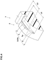
- FIG. 4 illustrates a perspective view of the groove 3.
- each groove 3 is configured as a lateral groove 3A that opens at a tread edge Te of the tread portion 2.
- length L5 in the tyre axial direction of the minimum portion 5 is equal to or more than 70% of a length L6 in the tyre axial direction of the lateral groove 3A.
- the length L6 in the tyre axial direction of the lateral groove 3A is a length in the tyre axial direction of the groove bottom portion 7.
- Such a groove 3 can provide a large ground contact length of the minimum portion 5 when braking, uneven wear resistance and grip performance of the tyre 1 can further be improved.
- the minimum portion 5 and the maximum portion 6 preferably extend with respective constant groove widths W1 and W2 in the longitudinal direction of the groove 3.
- Such a groove 3 can maintain uniform stiffness of the tyre 1 in the longitudinal direction of the groove 3, improving grip performance of the tyre 1 further.
- FIG. 5 illustrates a cross-sectional view of each groove 13 according to another embodiment.
- the groove 13 according to the embodiment includes the opening 14 formed on the tread surface 12a, the minimum portion 15 located inwardly in the tyre radial direction of the opening 14, and the maximum portion 16 located inwardly in the tyre radial direction of the minimum portion 15.
- the minimum portion 15 is a portion having a groove width W11 which is locally minimum.
- the maximum portion 16 is a portion having a groove width W12 which is locally maximum in a region inwardly in the tyre radial direction of the opening 14.
- the groove 13 includes the groove bottom portion 17 located innermost in the tyre radial direction of the groove.
- the minimum distance L11 in the tyre radial direction between the minimum portion 15 and the maximum portion 16 is greater than the minimum distance L12 in the tyre radial direction between the maximum portion 16 and the groove bottom portion 17.
- the groove width W13 of the opening 14 is greater than the groove width W12 of the maximum portion 16.
- a region from the opening 14 to the minimum portion 15 of the groove 13 is formed by a pair of inclined surfaces 18 inclined with respect to the tyre radial direction.
- the pair of inclined surfaces 18 each includes two planes 18a.
- Each inclined surface 18, for example, consists of a first plane 18A extending from the opening 14 and a second plane 18B extending from the minimum portion 15.
- Such an inclined surface 18 can disperse braking load effectively, improving uneven wear resistance of the tyre 1 further.
- each internal inclined surface 19 consists of a curved surface 19a.
- An angle ⁇ 2 of each internal inclined surface 19, for example, is defined as an angle relative to the tyre radial direction of a straight line connecting the minimum portion 15 and the maximum portion 16.
- FIG. 6 illustrates a cross-sectional view of yet another embodiment of each groove 23.
- the groove 23 according to the embodiment includes the opening 24 formed on the tread surface 22a, the minimum portion 25 located inwardly in the tyre radial direction of the opening 24, and the maximum portion 26 located inwardly in the tyre radial direction of the minimum portion 25.
- the minimum portion 25 is a portion having a groove width W21 which is locally minimum.
- the maximum portion 26 is a portion having a groove width W22 which is locally maximum in a region inwardly in the tyre radial direction of the opening 24.
- the groove 23 includes the groove bottom portion 27 located innermost in the tyre radial direction of the groove.
- the minimum distance L21 in the tyre radial direction between the minimum portion 25 and the maximum portion 26 is greater than the minimum distance L22 in the tyre radial direction between the maximum portion 26 and the groove bottom portion 27.
- the groove width W23 of the opening 24 is greater than the groove width W22 of the maximum portion 26.
- a region from the opening 24 to the minimum portion 25 of the groove 23 is formed by a pair of inclined surfaces 28 inclined with respect to the tyre radial direction.
- the pair of inclined surfaces 28 consists of a curved surface 28a. Such an inclined surface 28 can disperse braking load effectively, improving uneven wear resistance of the tyre 1 further.
- the inclined surfaces 28, for example may be configured to include a plane (not illustrated) and a curved surface.
- Such an inclined surface 28, the same as described the groove 3, can disperse braking load effectively, improving uneven wear resistance of the tyre 1 further.
Landscapes
- Engineering & Computer Science (AREA)
- Mechanical Engineering (AREA)
- Tires In General (AREA)
Description
- The present disclosure relates to tyres, more particularly to a tyre capable of improving uneven wear resistance and grip performance in a well-balanced manner.
- Conventionally, tyres which include improved cross-sectional shapes of grooves have been proposed. For example, the following Patent document 1 discloses a tyre tread provided with lateral cuts which include first part and ducts located radially inside the first parts in order to improve performance when the tread has worn down.
- [Patent document 1] Japanese Unexamined Patent Application Publication
2017-509531 - Document
WO 2017/072139 A1 discloses a tyre according to the preamble of claim 1. Furthermore, tyres showing the features of the preamble of claim 1 except the feature that a minimum distance in the tyre radial direction between the minimum portion and the opening is smaller than a minimum distance in the tyre radial direction between the minimum portion and the maximum portion are known from documentsJP H10 264613 A WO 2013/087440 A1 ,JP 2003 159911 A1 WO 2017/090332 A1 ,EP 2 900 489 A1GB 2 329 161 A - Unfortunately, the tyre disclosed in Patent document 1, due to the ducts provided inside the tread portion, tends to reduce in stiffness of the tread portion, resulting in deterioration of uneven wear resistance and grip performance.
- The present disclosure has been made in view of the above circumstances and has a major object to provide tyres capable of improving uneven wear resistance and grip performance in a well-balanced manner. The inventive tyre has the features of claim 1.
- According to one aspect of the disclosure, a tyre includes a tread portion having a tread surface provided with grooves extending in a tyre axial direction. Each groove includes an opening formed on the tread surface, a minimum portion located inwardly in a tyre radial direction of the opening and having a groove width being locally minimum, and a maximum portion located inwardly in the tyre radial direction of the minimum portion and having a groove width being locally maximum in a region inwardly in the tyre radial direction of the opening.
- In another aspect of the disclosure, each groove may include a groove bottom portion located innermost in the tyre radial direction, and a minimum distance in the tyre radial direction between the minimum portion and the maximum portion may be greater than a minimum distance in the tyre radial direction between the maximum portion and the groove bottom portion.
- In another aspect of the disclosure, a groove width of the opening may be greater than the groove width of the maximum portion.
- In the inventive tyre, a minimum distance in the tyre radial direction between the minimum portion and the opening is smaller than a minimum distance in the tyre radial direction between the minimum portion and the maximum portion.
- In another aspect of the disclosure, a minimum distance in the tyre radial direction between the minimum portion and the opening may be smaller than a minimum distance in the tyre radial direction between the maximum portion and a groove bottom portion.
- In another aspect of the disclosure, a minimum distance in the tyre radial direction between the minimum portion and the opening may be equal to or less than 40% of a minimum distance in the tyre radial direction between the opening and a groove bottom portion.
- In another aspect of the disclosure, each groove may include a groove bottom portion located innermost in the tyre radial direction, and the groove bottom portion is located on a center of a curved surface curved protruding inwardly in the tyre radial direction.
- In the inventive tyre, a region from the opening to the minimum portion of each groove is formed by a pair of inclined surfaces inclined with respect to the tyre radial direction.
- In another aspect of the disclosure, the pair of inclined surfaces each may be one or more planes.
- In another aspect of the disclosure, the pair of the inclined surfaces may be a curved surface.
- In another aspect of the disclosure, the pair of inclined surfaces may include one or more planes and a curved surface.
- In another aspect of the disclosure, each groove may be a lateral groove in communication with a tread edge of the tread portion.
-
-
FIG. 1 is a side view of a tyre according to an embodiment of the present disclosure; -
FIG. 2 is a cross-sectional view of a groove; -
FIG. 3 is a cross-sectional view of the groove upon grounding; -
FIG. 4 is a perspective view of the groove; -
FIG. 5 is a cross-sectional view of the groove according to another embodiment; and -
FIG. 6 is a cross-sectional view of the groove according to yet another embodiment. - An embodiment of the present disclosure will be explained below with reference to the accompanying drawings.
-
FIG. 1 illustrates a side view of a tyre 1 according to an embodiment. - The tyre 1 according to the present disclosure can be used for various kinds of tyres, e.g., pneumatic tyres for passenger car and heavy-duty vehicle, and non-pneumatic tyres that can support the tyre load by structural members without being inflated with a pressurized air. As illustrated in
FIG. 1 , the tyre 1 according to the embodiment includes atread portion 2 having atread surface 2a provided withgrooves 3 extending in the tyre axial direction. -
FIG. 2 is a cross-sectional view of onegroove 3. As illustrated inFIG. 2 , eachgroove 3 includes anopening 4 formed on thetread surface 2a, aminimum portion 5 located inwardly in the tyre radial direction of theopening 4, and amaximum portion 6 located inwardly in the tyre radial direction of theminimum portion 5. Theminimum portion 5 is a portion having a groove width W1 which is locally minimum. Themaximum portion 6 is a portion having a groove width W2 which is locally maximum in a region inwardly in the tyre radial direction of theopening 4. - As used herein, dimensions of respective portions of the tyre 1 are values measured under a normal state unless otherwise noted. As used herein, the normal state is such that the tyre 1, when the tyre 1 is a pneumatic tyre, is mounted on a standard wheel rim with a standard pressure but is loaded with no tyre load.
- The standard wheel rim is a wheel rim officially approved for each tyre by standards organizations on which the tyre 1 is based, wherein the standard wheel rim is the "standard rim" specified in JATMA, the "Design Rim" in TRA, and the "Measuring Rim" in ETRTO, for example.
- The standard pressure is a standard pressure officially approved for each tyre by standards organizations on which the tyre is based, wherein the standard pressure is the "maximum air pressure" in JATMA, the maximum pressure given in the "Tire Load Limits at Various Cold Inflation Pressures" table in TRA, and the "Inflation Pressure" in ETRTO, for example.
-
FIG. 3 illustrates a cross-sectional view of thegroove 3 upon grounding. As illustrated inFIG. 3 , thegroove 3 can moderate braking load by a region between theopening 4 and theminimum portion 5, improving uneven wear resistance of the tyre 1. In addition, theminimum portion 5, due to braking load, approaches the ground and then comes into contact with it, and thus a ground contact area of the tyre 1 increases so as to improve grip performance. In addition, themaximum portion 6, due to its large cross-sectional area, can maintain flexibility thereof appropriately, improving uneven wear resistance of the tyre 1 further. - As illustrated in
FIG. 2 , in some preferred embodiments, eachgroove 3 includes agroove bottom portion 7 located innermost thereof in the tyre radial direction. It is preferable that the minimum distance L1 in the tyre radial direction between theminimum portion 5 and themaximum portion 6 is greater than the minimum distance L2 in the tyre radial direction between themaximum portion 6 and thegroove bottom portion 7. In such a tyre 1, since themaximum portion 6 is located inwardly in the tyre radial direction of the center location of a region between theminimum portion 5 and thegroove bottom portion 7, reduction in stiffness due to themaximum portion 6 can be suppressed, and thus grip performance of the tyre 1 can be improved. - In the inventive tyre, the minimum distance L3 in the tyre radial direction between the
minimum portion 5 and theopening 4 is smaller than the minimum distance L1 in the tyre radial direction between theminimum portion 5 and themaximum portion 6. Further, it is preferable that the minimum distance L3 in the tyre radial direction between theminimum portion 5 and theopening 4 is smaller than the minimum distance L2 in the tyre radial direction between themaximum portion 6 and thegroove bottom portion 7. Such agroove 3 can maintain stiffness of the tyre 1 within a proper range, improving uneven wear resistance and grip performance in a high level. - Preferably, the minimum distance L3 in the tyre radial direction between the
minimum portion 5 and theopening 4 is equal to or less than 40% of the minimum distance L4 in the tyre radial direction between the opening 4 and thegroove bottom portion 7. Note that the minimum distance L4 between theopening 4 and thegroove bottom portion 7 corresponds to a groove depth of thegroove 3. When the minimum distance L3 between theminimum portion 5 and theopening 4 is more than 40% of the minimum distance L4 between the opening 4 and thegroove bottom portion 7, braking load tends to act on the opening 4 locally, and thus uneven wear resistance of the tyre 1 may not be improved. - In the present embodiment, a groove width W3 of the
opening 4 is greater than the groove width W2 of themaximum portion 6. Such anopening 4 can increase the groove width difference between theminimum portion 5 and theopening 4 while maintaining the minimum distance L3 between theminimum portion 5 and theopening 4. Thus, thegroove 3 can disperse braking load, improving uneven wear resistance of the tyre 1. - In the inventive tyre, a region from the opening 4 to the
minimum portion 5 of eachgroove 3 is formed by a pair ofinclined surfaces 8 inclined with respect to the tyre radial direction. In the present embodiment, the pair ofinclined surfaces 8 each consists of asingle plane 8a. Such aninclined surface 8 can come into contact with the ground appropriately (shown inFIG. 3 ) by receiving braking load, resulting in increase of a ground contact area of the tyre 1 so that grip performance of the tyre 1 is improved. - Preferably, the
plane 8a of eachinclined surface 8 has an angle θ1 of from 5 to 30 degrees with respect to thetread surface 2a. When the angles θ1 of theinclined surface 8 is less than 5 degrees, braking load tends to act on theminimum portion 5 locally, and there is a risk that uneven wear resistance of the tyre 1 does not improve. When the angle θ1 of theinclined surface 8 is more than 30 degrees, braking load tends to act on theopening 4 locally, and there is a risk that uneven wear resistance of the tyre 1 does not improve. - In the present embodiment, a region from the
minimum portion 5 to themaximum portion 6 of eachgroove 3 is formed by a pair of internalinclined surfaces 9 inclined with respect to the tyre radial direction. In the present embodiment, the pair of internalinclined surfaces 9 includes aplane 9a and acurved surface 9b. Such agroove 3 can make the groove width W2 of themaximum portion 6 wider while maintaining stiffness of the tyre 1, improving uneven wear resistance and grip performance of the tyre in a high level. - Preferably, the
plane 9a of each internalinclined surface 9 is inclined at an angle θ2 of from 5 to 25 degrees with respect to the tyre radial direction. When the angle θ2 ofplane 9a of each internalinclined surface 9 is less than 5 degrees, the groove width W2 of themaximum portion 6 becomes small, and thus there is a risk that uneven wear resistance of the tyre 1 may not improve. When the angle θ2 ofplane 9a of each internalinclined surface 9 is more than 25 degrees, stiffness of the tyre 1 tends decrease, and thus there is a risk that grip performance of the tyre may not improve. - A region from the
maximum portion 6 to thegroove bottom portion 7 of thegroove 3 according to the embodiment is configured as acurved surface 7a curving in the groove width direction. Preferably, thegroove bottom portion 7 is located on the middle position of thecurved surface 7a in the groove width direction. Thus, thegroove 3 according to the embodiment, has the deepest groove depth at the middle position in the groove width direction of the groove. Note that the deepest groove depth of thegroove 3 is the minimum distance L4 in the tyre radial direction between theopening 4 and thegroove bottom portion 7. Such agroove 3 can maintain stiffness of the tyre 1, thus improving grip performance of the tyre 1. -
FIG. 4 illustrates a perspective view of thegroove 3. As illustrated inFIG. 4 , eachgroove 3 is configured as alateral groove 3A that opens at a tread edge Te of thetread portion 2. Preferably, length L5 in the tyre axial direction of theminimum portion 5 is equal to or more than 70% of a length L6 in the tyre axial direction of thelateral groove 3A. Note that the length L6 in the tyre axial direction of thelateral groove 3A is a length in the tyre axial direction of thegroove bottom portion 7. Such agroove 3 can provide a large ground contact length of theminimum portion 5 when braking, uneven wear resistance and grip performance of the tyre 1 can further be improved. - As illustrated in
FIG. 2 andFIG. 4 , theminimum portion 5 and themaximum portion 6 preferably extend with respective constant groove widths W1 and W2 in the longitudinal direction of thegroove 3. Such agroove 3 can maintain uniform stiffness of the tyre 1 in the longitudinal direction of thegroove 3, improving grip performance of the tyre 1 further. -
FIG. 5 illustrates a cross-sectional view of eachgroove 13 according to another embodiment. As illustrated inFIG. 5 , thegroove 13 according to the embodiment includes theopening 14 formed on thetread surface 12a, theminimum portion 15 located inwardly in the tyre radial direction of theopening 14, and themaximum portion 16 located inwardly in the tyre radial direction of theminimum portion 15. Theminimum portion 15 is a portion having a groove width W11 which is locally minimum. Themaximum portion 16 is a portion having a groove width W12 which is locally maximum in a region inwardly in the tyre radial direction of theopening 14. - In this embodiment, the
groove 13 includes thegroove bottom portion 17 located innermost in the tyre radial direction of the groove. Preferably, the minimum distance L11 in the tyre radial direction between theminimum portion 15 and themaximum portion 16 is greater than the minimum distance L12 in the tyre radial direction between themaximum portion 16 and thegroove bottom portion 17. Even in the present embodiment, it is preferable that the groove width W13 of theopening 14 is greater than the groove width W12 of themaximum portion 16. Such agroove 13, the same as described thegroove 3, can improve uneven wear resistance and grip performance of the tyre 1 in a well-balance manner. - In this embodiment, a region from the
opening 14 to theminimum portion 15 of thegroove 13 is formed by a pair ofinclined surfaces 18 inclined with respect to the tyre radial direction. In the present embodiment, the pair ofinclined surfaces 18 each includes twoplanes 18a. Eachinclined surface 18, for example, consists of afirst plane 18A extending from theopening 14 and asecond plane 18B extending from theminimum portion 15. Such aninclined surface 18 can disperse braking load effectively, improving uneven wear resistance of the tyre 1 further. - In the present embodiment, a region from the
minimum portion 15 to themaximum portion 16 of eachgroove 13 is formed by a pair of internalinclined surfaces 19 inclined with respect to the tyre radial direction. In the present embodiment, each internalinclined surface 19 consists of acurved surface 19a. An angle θ2 of each internalinclined surface 19, for example, is defined as an angle relative to the tyre radial direction of a straight line connecting theminimum portion 15 and themaximum portion 16. Such agroove 13 can make the groove width W12 of themaximum portion 16 wider while maintaining stiffness of the tyre 1, improving uneven wear resistance and grip performance of the tyre in a high level, resulting in improving both uneven wear resistance and grip performance of the tyre. -
FIG. 6 illustrates a cross-sectional view of yet another embodiment of eachgroove 23. As illustrated inFIG. 6 , thegroove 23 according to the embodiment includes theopening 24 formed on thetread surface 22a, theminimum portion 25 located inwardly in the tyre radial direction of theopening 24, and themaximum portion 26 located inwardly in the tyre radial direction of theminimum portion 25. Theminimum portion 25 is a portion having a groove width W21 which is locally minimum. Themaximum portion 26 is a portion having a groove width W22 which is locally maximum in a region inwardly in the tyre radial direction of theopening 24. - In this embodiment, the
groove 23 includes thegroove bottom portion 27 located innermost in the tyre radial direction of the groove. Preferably, the minimum distance L21 in the tyre radial direction between theminimum portion 25 and themaximum portion 26 is greater than the minimum distance L22 in the tyre radial direction between themaximum portion 26 and thegroove bottom portion 27. Even in the present embodiment, it is preferable that the groove width W23 of theopening 24 is greater than the groove width W22 of themaximum portion 26. Such agroove 23, the same as described thegroove 3, can improve uneven wear resistance and grip performance of the tyre 1 in a well-balanced manner. - In this embodiment, a region from the
opening 24 to theminimum portion 25 of thegroove 23 is formed by a pair ofinclined surfaces 28 inclined with respect to the tyre radial direction. In the present embodiment, the pair ofinclined surfaces 28 consists of acurved surface 28a. Such aninclined surface 28 can disperse braking load effectively, improving uneven wear resistance of the tyre 1 further. - Alternatively, the
inclined surfaces 28, for example, may be configured to include a plane (not illustrated) and a curved surface. Such aninclined surface 28, the same as described thegroove 3, can disperse braking load effectively, improving uneven wear resistance of the tyre 1 further. - While the particularly preferable embodiments in accordance with the present disclosure have been described in detail, the present disclosure is not limited to the illustrated embodiments, but can be modified and carried out in various aspects, within the scope of the appended claims.
Claims (10)
- A tyre (1) comprising:a tread portion (2) having a tread surface (2a) provided with grooves (3) extending in a tyre axial direction; andeach groove (3) comprisingan opening (4) formed on the tread surface (2a),a minimum portion (5) located inwardly in a tyre radial direction of the opening (4) and having a groove width (W1) being locally minimum, anda maximum portion (6) located inwardly in the tyre radial direction of the minimum portion (5) and having a groove width (W2) being locally maximum in a region inwardly in the tyre radial direction of the opening, whereina minimum distance (L3) in the tyre radial direction between the minimum portion (5) and the opening (4) is smaller than a minimum distance (L1) in the tyre radial direction between the minimum portion (5) and the maximum portion (6),characterized in thata region from the opening (4) to the minimum portion (5) of each groove (3) is formed by a pair of inclined surfaces (8) inclined with respect to the tyre radial direction.
- The tyre (1) according to claim 1, wherein
each groove (3) comprises a groove bottom portion (7) located innermost in the tyre radial direction, and a minimum distance (L1) in the tyre radial direction between the minimum portion (5) and the maximum portion (6) is greater than a minimum distance (L2) in the tyre radial direction between the maximum portion (6) and the groove bottom portion (7). - The tyre (1) according to claim 1 or 2, wherein
a groove width (W3) of the opening (4) is greater than the groove width (W2) of the maximum portion (6). - The tyre (1) according to any one of claims 1 to 3, wherein
a minimum distance (L3) in the tyre radial direction between the minimum portion (5) and the opening (4) is smaller than a minimum distance (L2) in the tyre radial direction between the maximum portion (6) and a groove bottom portion (7). - The tyre (1) according to any one of claims 1 to 4, wherein
a minimum distance (L3) in the tyre radial direction between the minimum portion (5) and the opening (4) is equal to or less than 40% of a minimum distance (L2) in the tyre radial direction between the opening (4) and a groove bottom portion (7). - The tyre (1) according to any one of claims 1 to 5, wherein
each groove comprises a groove bottom portion (7) located innermost in the tyre radial direction, and
the groove bottom portion (7) is located on a center of a curved surface curved protruding inwardly in the tyre radial direction. - The tyre (1) according to any of of claims 1 to 6, wherein
the pair of inclined surfaces (8) each is one or more planes. - The tyre (1) according to any one of claims 1 to 6, wherein
the pair of the inclined surfaces (8) is a curved surface. - The tyre (1) according to any of of claims 1 to 6, wherein
the pair of inclined surfaces (8) includes one or more planes and a curved surface. - The tyre (1) according to any one of claims 1 to 9, wherein
each groove (3) is a lateral groove in communication with a tread edge (Te) of the tread portion (2).
Applications Claiming Priority (1)
| Application Number | Priority Date | Filing Date | Title |
|---|---|---|---|
| JP2018080116A JP7110699B2 (en) | 2018-04-18 | 2018-04-18 | tire |
Publications (2)
| Publication Number | Publication Date |
|---|---|
| EP3556575A1 EP3556575A1 (en) | 2019-10-23 |
| EP3556575B1 true EP3556575B1 (en) | 2021-01-20 |
Family
ID=65991585
Family Applications (1)
| Application Number | Title | Priority Date | Filing Date |
|---|---|---|---|
| EP19165134.8A Active EP3556575B1 (en) | 2018-04-18 | 2019-03-26 | Tyre |
Country Status (3)
| Country | Link |
|---|---|
| US (1) | US11446964B2 (en) |
| EP (1) | EP3556575B1 (en) |
| JP (1) | JP7110699B2 (en) |
Families Citing this family (3)
| Publication number | Priority date | Publication date | Assignee | Title |
|---|---|---|---|---|
| JP7563080B2 (en) * | 2020-09-28 | 2024-10-08 | 住友ゴム工業株式会社 | tire |
| JP7625835B2 (en) * | 2020-11-24 | 2025-02-04 | 住友ゴム工業株式会社 | tire |
| JP7631764B2 (en) * | 2020-12-01 | 2025-02-19 | 住友ゴム工業株式会社 | tire |
Family Cites Families (24)
| Publication number | Priority date | Publication date | Assignee | Title |
|---|---|---|---|---|
| FR2312385A1 (en) * | 1975-05-30 | 1976-12-24 | Uniroyal | TREAD STRUCTURE AND PNEUMATIC BANDAGE WRAP WITH APPLICATION |
| JPS62286803A (en) * | 1986-06-04 | 1987-12-12 | Bridgestone Corp | Pneumatic tyre |
| JP3096357B2 (en) * | 1992-06-04 | 2000-10-10 | 住友ゴム工業株式会社 | Heavy duty pneumatic tires |
| JP2774775B2 (en) * | 1993-08-23 | 1998-07-09 | 住友ゴム工業株式会社 | Pneumatic tire |
| JP3323630B2 (en) * | 1994-02-04 | 2002-09-09 | 株式会社ブリヂストン | Pneumatic tire |
| JP3720519B2 (en) * | 1997-03-26 | 2005-11-30 | 株式会社ブリヂストン | Pneumatic radial tires for passenger cars or light trucks traveling on rough roads |
| GB2329161A (en) * | 1997-09-13 | 1999-03-17 | Sumitomo Rubber Ind | Vehicle tyre treads |
| DE60025587T2 (en) * | 1999-02-22 | 2006-07-13 | Bridgestone Corp. | TIRE |
| JP4216545B2 (en) | 2001-09-17 | 2009-01-28 | 株式会社ブリヂストン | Pneumatic tire |
| FR2878190B1 (en) * | 2004-11-24 | 2007-01-12 | Michelin Soc Tech | CROSS-SECTIONAL BEARING GROOVE GROOVE PROFILE |
| EP2234824B1 (en) * | 2007-12-21 | 2015-05-27 | Compagnie Générale des Etablissements Michelin | Mechanisms for ejecting objects from a tire tread |
| KR20100041480A (en) * | 2008-10-14 | 2010-04-22 | 한국타이어 주식회사 | Automotive snow tires with improved holes |
| DE102010017010A1 (en) | 2010-05-18 | 2011-11-24 | Continental Reifen Deutschland Gmbh | Tread profile for vehicle pneumatic tire, has profile block row, which is limited in both axial directions by circumferential grooves, where radial external surface is formed in cross sectional planes |
| KR101267970B1 (en) * | 2011-11-07 | 2013-05-27 | 한국타이어 주식회사 | Groove of pneumatic tire improved drain performance |
| DE102011056427A1 (en) * | 2011-12-14 | 2013-06-20 | Continental Reifen Deutschland Gmbh | Pneumatic vehicle tires for commercial vehicles |
| DE102012109069A1 (en) * | 2012-09-26 | 2014-05-15 | Continental Reifen Deutschland Gmbh | Vehicle tires |
| RU2640666C2 (en) * | 2012-12-28 | 2018-01-11 | Компани Женераль Дэз Этаблиссман Мишлен | Pneumatic tire tread and pneumatic tire with such tread |
| FR3019096B1 (en) | 2014-03-31 | 2016-03-18 | Michelin & Cie | TREAD BAND HAVING CHANNELS ON ITS EDGES |
| FR3042738B1 (en) * | 2015-10-27 | 2017-11-24 | Michelin & Cie | PNEUMATIC WORKING LAYER COMPRISING MONOFILAMENTS AND GROOVED ROLLING BELT |
| JP6744085B2 (en) * | 2015-11-17 | 2020-08-19 | Toyo Tire株式会社 | Pneumatic tire |
| JP6621312B2 (en) * | 2015-11-24 | 2019-12-18 | 株式会社ブリヂストン | Pneumatic tire |
| JP6781541B2 (en) * | 2015-12-10 | 2020-11-04 | Toyo Tire株式会社 | Pneumatic tires |
| JP6623764B2 (en) * | 2016-01-06 | 2019-12-25 | 住友ゴム工業株式会社 | Pneumatic tire |
| WO2019111756A1 (en) * | 2017-12-08 | 2019-06-13 | 株式会社ブリヂストン | Tire |
-
2018
- 2018-04-18 JP JP2018080116A patent/JP7110699B2/en active Active
-
2019
- 2019-03-21 US US16/360,234 patent/US11446964B2/en active Active
- 2019-03-26 EP EP19165134.8A patent/EP3556575B1/en active Active
Non-Patent Citations (1)
| Title |
|---|
| None * |
Also Published As
| Publication number | Publication date |
|---|---|
| US20190322141A1 (en) | 2019-10-24 |
| EP3556575A1 (en) | 2019-10-23 |
| JP2019188850A (en) | 2019-10-31 |
| US11446964B2 (en) | 2022-09-20 |
| JP7110699B2 (en) | 2022-08-02 |
Similar Documents
| Publication | Publication Date | Title |
|---|---|---|
| EP3296127B1 (en) | Pneumatic tire | |
| EP3260308B1 (en) | Tire | |
| EP3647077B1 (en) | Tire | |
| EP3056359B1 (en) | Pneumatic tire | |
| EP2789481B1 (en) | Tread band of a pneumatic tire | |
| EP3162593B1 (en) | Tire | |
| EP3318421B1 (en) | Tire | |
| CN109203865B (en) | Pneumatic tire | |
| EP3269564A1 (en) | Pneumatic tire | |
| EP3398793B1 (en) | Tire | |
| EP2777950B1 (en) | Pneumatic tire | |
| US10981418B2 (en) | Tire | |
| EP3549794B1 (en) | Tyre | |
| EP3647078B1 (en) | Tyre | |
| EP3421265B1 (en) | Tire | |
| EP3611039B1 (en) | Tire | |
| EP4151434B1 (en) | Tire | |
| EP3556575B1 (en) | Tyre | |
| EP3689642B1 (en) | Tire | |
| EP3354484B1 (en) | Tire | |
| EP3686035B1 (en) | Tire | |
| US11135877B2 (en) | Tire | |
| EP4074522B1 (en) | Tyre | |
| EP3689641B1 (en) | Tire tread | |
| EP3549793B1 (en) | Tyre |
Legal Events
| Date | Code | Title | Description |
|---|---|---|---|
| PUAI | Public reference made under article 153(3) epc to a published international application that has entered the european phase |
Free format text: ORIGINAL CODE: 0009012 |
|
| STAA | Information on the status of an ep patent application or granted ep patent |
Free format text: STATUS: THE APPLICATION HAS BEEN PUBLISHED |
|
| AK | Designated contracting states |
Kind code of ref document: A1 Designated state(s): AL AT BE BG CH CY CZ DE DK EE ES FI FR GB GR HR HU IE IS IT LI LT LU LV MC MK MT NL NO PL PT RO RS SE SI SK SM TR |
|
| AX | Request for extension of the european patent |
Extension state: BA ME |
|
| STAA | Information on the status of an ep patent application or granted ep patent |
Free format text: STATUS: REQUEST FOR EXAMINATION WAS MADE |
|
| 17P | Request for examination filed |
Effective date: 20200320 |
|
| RBV | Designated contracting states (corrected) |
Designated state(s): AL AT BE BG CH CY CZ DE DK EE ES FI FR GB GR HR HU IE IS IT LI LT LU LV MC MK MT NL NO PL PT RO RS SE SI SK SM TR |
|
| RIC1 | Information provided on ipc code assigned before grant |
Ipc: B60C 11/03 20060101ALI20200804BHEP Ipc: B60C 11/04 20060101AFI20200804BHEP Ipc: B60C 11/12 20060101ALI20200804BHEP |
|
| GRAP | Despatch of communication of intention to grant a patent |
Free format text: ORIGINAL CODE: EPIDOSNIGR1 |
|
| STAA | Information on the status of an ep patent application or granted ep patent |
Free format text: STATUS: GRANT OF PATENT IS INTENDED |
|
| INTG | Intention to grant announced |
Effective date: 20201001 |
|
| GRAS | Grant fee paid |
Free format text: ORIGINAL CODE: EPIDOSNIGR3 |
|
| GRAA | (expected) grant |
Free format text: ORIGINAL CODE: 0009210 |
|
| STAA | Information on the status of an ep patent application or granted ep patent |
Free format text: STATUS: THE PATENT HAS BEEN GRANTED |
|
| AK | Designated contracting states |
Kind code of ref document: B1 Designated state(s): AL AT BE BG CH CY CZ DE DK EE ES FI FR GB GR HR HU IE IS IT LI LT LU LV MC MK MT NL NO PL PT RO RS SE SI SK SM TR |
|
| REG | Reference to a national code |
Ref country code: GB Ref legal event code: FG4D |
|
| REG | Reference to a national code |
Ref country code: CH Ref legal event code: EP |
|
| REG | Reference to a national code |
Ref country code: DE Ref legal event code: R096 Ref document number: 602019002232 Country of ref document: DE |
|
| REG | Reference to a national code |
Ref country code: AT Ref legal event code: REF Ref document number: 1356073 Country of ref document: AT Kind code of ref document: T Effective date: 20210215 |
|
| REG | Reference to a national code |
Ref country code: IE Ref legal event code: FG4D |
|
| REG | Reference to a national code |
Ref country code: NL Ref legal event code: MP Effective date: 20210120 |
|
| REG | Reference to a national code |
Ref country code: LT Ref legal event code: MG9D |
|
| REG | Reference to a national code |
Ref country code: AT Ref legal event code: MK05 Ref document number: 1356073 Country of ref document: AT Kind code of ref document: T Effective date: 20210120 |
|
| PG25 | Lapsed in a contracting state [announced via postgrant information from national office to epo] |
Ref country code: BG Free format text: LAPSE BECAUSE OF FAILURE TO SUBMIT A TRANSLATION OF THE DESCRIPTION OR TO PAY THE FEE WITHIN THE PRESCRIBED TIME-LIMIT Effective date: 20210420 Ref country code: HR Free format text: LAPSE BECAUSE OF FAILURE TO SUBMIT A TRANSLATION OF THE DESCRIPTION OR TO PAY THE FEE WITHIN THE PRESCRIBED TIME-LIMIT Effective date: 20210120 Ref country code: FI Free format text: LAPSE BECAUSE OF FAILURE TO SUBMIT A TRANSLATION OF THE DESCRIPTION OR TO PAY THE FEE WITHIN THE PRESCRIBED TIME-LIMIT Effective date: 20210120 Ref country code: GR Free format text: LAPSE BECAUSE OF FAILURE TO SUBMIT A TRANSLATION OF THE DESCRIPTION OR TO PAY THE FEE WITHIN THE PRESCRIBED TIME-LIMIT Effective date: 20210421 Ref country code: LT Free format text: LAPSE BECAUSE OF FAILURE TO SUBMIT A TRANSLATION OF THE DESCRIPTION OR TO PAY THE FEE WITHIN THE PRESCRIBED TIME-LIMIT Effective date: 20210120 Ref country code: PT Free format text: LAPSE BECAUSE OF FAILURE TO SUBMIT A TRANSLATION OF THE DESCRIPTION OR TO PAY THE FEE WITHIN THE PRESCRIBED TIME-LIMIT Effective date: 20210520 Ref country code: NO Free format text: LAPSE BECAUSE OF FAILURE TO SUBMIT A TRANSLATION OF THE DESCRIPTION OR TO PAY THE FEE WITHIN THE PRESCRIBED TIME-LIMIT Effective date: 20210420 |
|
| PG25 | Lapsed in a contracting state [announced via postgrant information from national office to epo] |
Ref country code: LV Free format text: LAPSE BECAUSE OF FAILURE TO SUBMIT A TRANSLATION OF THE DESCRIPTION OR TO PAY THE FEE WITHIN THE PRESCRIBED TIME-LIMIT Effective date: 20210120 Ref country code: RS Free format text: LAPSE BECAUSE OF FAILURE TO SUBMIT A TRANSLATION OF THE DESCRIPTION OR TO PAY THE FEE WITHIN THE PRESCRIBED TIME-LIMIT Effective date: 20210120 Ref country code: PL Free format text: LAPSE BECAUSE OF FAILURE TO SUBMIT A TRANSLATION OF THE DESCRIPTION OR TO PAY THE FEE WITHIN THE PRESCRIBED TIME-LIMIT Effective date: 20210120 Ref country code: AT Free format text: LAPSE BECAUSE OF FAILURE TO SUBMIT A TRANSLATION OF THE DESCRIPTION OR TO PAY THE FEE WITHIN THE PRESCRIBED TIME-LIMIT Effective date: 20210120 Ref country code: SE Free format text: LAPSE BECAUSE OF FAILURE TO SUBMIT A TRANSLATION OF THE DESCRIPTION OR TO PAY THE FEE WITHIN THE PRESCRIBED TIME-LIMIT Effective date: 20210120 |
|
| PG25 | Lapsed in a contracting state [announced via postgrant information from national office to epo] |
Ref country code: IS Free format text: LAPSE BECAUSE OF FAILURE TO SUBMIT A TRANSLATION OF THE DESCRIPTION OR TO PAY THE FEE WITHIN THE PRESCRIBED TIME-LIMIT Effective date: 20210520 |
|
| REG | Reference to a national code |
Ref country code: DE Ref legal event code: R097 Ref document number: 602019002232 Country of ref document: DE |
|
| PG25 | Lapsed in a contracting state [announced via postgrant information from national office to epo] |
Ref country code: SM Free format text: LAPSE BECAUSE OF FAILURE TO SUBMIT A TRANSLATION OF THE DESCRIPTION OR TO PAY THE FEE WITHIN THE PRESCRIBED TIME-LIMIT Effective date: 20210120 Ref country code: MC Free format text: LAPSE BECAUSE OF FAILURE TO SUBMIT A TRANSLATION OF THE DESCRIPTION OR TO PAY THE FEE WITHIN THE PRESCRIBED TIME-LIMIT Effective date: 20210120 Ref country code: CZ Free format text: LAPSE BECAUSE OF FAILURE TO SUBMIT A TRANSLATION OF THE DESCRIPTION OR TO PAY THE FEE WITHIN THE PRESCRIBED TIME-LIMIT Effective date: 20210120 Ref country code: EE Free format text: LAPSE BECAUSE OF FAILURE TO SUBMIT A TRANSLATION OF THE DESCRIPTION OR TO PAY THE FEE WITHIN THE PRESCRIBED TIME-LIMIT Effective date: 20210120 |
|
| PLBE | No opposition filed within time limit |
Free format text: ORIGINAL CODE: 0009261 |
|
| STAA | Information on the status of an ep patent application or granted ep patent |
Free format text: STATUS: NO OPPOSITION FILED WITHIN TIME LIMIT |
|
| PG25 | Lapsed in a contracting state [announced via postgrant information from national office to epo] |
Ref country code: SK Free format text: LAPSE BECAUSE OF FAILURE TO SUBMIT A TRANSLATION OF THE DESCRIPTION OR TO PAY THE FEE WITHIN THE PRESCRIBED TIME-LIMIT Effective date: 20210120 Ref country code: RO Free format text: LAPSE BECAUSE OF FAILURE TO SUBMIT A TRANSLATION OF THE DESCRIPTION OR TO PAY THE FEE WITHIN THE PRESCRIBED TIME-LIMIT Effective date: 20210120 Ref country code: DK Free format text: LAPSE BECAUSE OF FAILURE TO SUBMIT A TRANSLATION OF THE DESCRIPTION OR TO PAY THE FEE WITHIN THE PRESCRIBED TIME-LIMIT Effective date: 20210120 |
|
| REG | Reference to a national code |
Ref country code: BE Ref legal event code: MM Effective date: 20210331 |
|
| 26N | No opposition filed |
Effective date: 20211021 |
|
| PG25 | Lapsed in a contracting state [announced via postgrant information from national office to epo] |
Ref country code: IE Free format text: LAPSE BECAUSE OF NON-PAYMENT OF DUE FEES Effective date: 20210326 Ref country code: LU Free format text: LAPSE BECAUSE OF NON-PAYMENT OF DUE FEES Effective date: 20210326 Ref country code: AL Free format text: LAPSE BECAUSE OF FAILURE TO SUBMIT A TRANSLATION OF THE DESCRIPTION OR TO PAY THE FEE WITHIN THE PRESCRIBED TIME-LIMIT Effective date: 20210120 Ref country code: ES Free format text: LAPSE BECAUSE OF FAILURE TO SUBMIT A TRANSLATION OF THE DESCRIPTION OR TO PAY THE FEE WITHIN THE PRESCRIBED TIME-LIMIT Effective date: 20210120 |
|
| PG25 | Lapsed in a contracting state [announced via postgrant information from national office to epo] |
Ref country code: SI Free format text: LAPSE BECAUSE OF FAILURE TO SUBMIT A TRANSLATION OF THE DESCRIPTION OR TO PAY THE FEE WITHIN THE PRESCRIBED TIME-LIMIT Effective date: 20210120 |
|
| PG25 | Lapsed in a contracting state [announced via postgrant information from national office to epo] |
Ref country code: IT Free format text: LAPSE BECAUSE OF FAILURE TO SUBMIT A TRANSLATION OF THE DESCRIPTION OR TO PAY THE FEE WITHIN THE PRESCRIBED TIME-LIMIT Effective date: 20210120 |
|
| PG25 | Lapsed in a contracting state [announced via postgrant information from national office to epo] |
Ref country code: IS Free format text: LAPSE BECAUSE OF FAILURE TO SUBMIT A TRANSLATION OF THE DESCRIPTION OR TO PAY THE FEE WITHIN THE PRESCRIBED TIME-LIMIT Effective date: 20210520 |
|
| PG25 | Lapsed in a contracting state [announced via postgrant information from national office to epo] |
Ref country code: BE Free format text: LAPSE BECAUSE OF NON-PAYMENT OF DUE FEES Effective date: 20210331 |
|
| REG | Reference to a national code |
Ref country code: CH Ref legal event code: PL |
|
| PG25 | Lapsed in a contracting state [announced via postgrant information from national office to epo] |
Ref country code: LI Free format text: LAPSE BECAUSE OF NON-PAYMENT OF DUE FEES Effective date: 20220331 Ref country code: CH Free format text: LAPSE BECAUSE OF NON-PAYMENT OF DUE FEES Effective date: 20220331 |
|
| P01 | Opt-out of the competence of the unified patent court (upc) registered |
Effective date: 20230510 |
|
| PG25 | Lapsed in a contracting state [announced via postgrant information from national office to epo] |
Ref country code: NL Free format text: LAPSE BECAUSE OF NON-PAYMENT OF DUE FEES Effective date: 20210120 Ref country code: CY Free format text: LAPSE BECAUSE OF FAILURE TO SUBMIT A TRANSLATION OF THE DESCRIPTION OR TO PAY THE FEE WITHIN THE PRESCRIBED TIME-LIMIT Effective date: 20210120 |
|
| PG25 | Lapsed in a contracting state [announced via postgrant information from national office to epo] |
Ref country code: HU Free format text: LAPSE BECAUSE OF FAILURE TO SUBMIT A TRANSLATION OF THE DESCRIPTION OR TO PAY THE FEE WITHIN THE PRESCRIBED TIME-LIMIT; INVALID AB INITIO Effective date: 20190326 |
|
| GBPC | Gb: european patent ceased through non-payment of renewal fee |
Effective date: 20230326 |
|
| PG25 | Lapsed in a contracting state [announced via postgrant information from national office to epo] |
Ref country code: GB Free format text: LAPSE BECAUSE OF NON-PAYMENT OF DUE FEES Effective date: 20230326 |
|
| PG25 | Lapsed in a contracting state [announced via postgrant information from national office to epo] |
Ref country code: GB Free format text: LAPSE BECAUSE OF NON-PAYMENT OF DUE FEES Effective date: 20230326 |
|
| PG25 | Lapsed in a contracting state [announced via postgrant information from national office to epo] |
Ref country code: MK Free format text: LAPSE BECAUSE OF FAILURE TO SUBMIT A TRANSLATION OF THE DESCRIPTION OR TO PAY THE FEE WITHIN THE PRESCRIBED TIME-LIMIT Effective date: 20210120 |
|
| PG25 | Lapsed in a contracting state [announced via postgrant information from national office to epo] |
Ref country code: MT Free format text: LAPSE BECAUSE OF FAILURE TO SUBMIT A TRANSLATION OF THE DESCRIPTION OR TO PAY THE FEE WITHIN THE PRESCRIBED TIME-LIMIT Effective date: 20210120 |
|
| PGFP | Annual fee paid to national office [announced via postgrant information from national office to epo] |
Ref country code: DE Payment date: 20250128 Year of fee payment: 7 |
|
| PGFP | Annual fee paid to national office [announced via postgrant information from national office to epo] |
Ref country code: FR Payment date: 20250210 Year of fee payment: 7 |
|
| PG25 | Lapsed in a contracting state [announced via postgrant information from national office to epo] |
Ref country code: TR Free format text: LAPSE BECAUSE OF FAILURE TO SUBMIT A TRANSLATION OF THE DESCRIPTION OR TO PAY THE FEE WITHIN THE PRESCRIBED TIME-LIMIT Effective date: 20210120 |