EP3556569B1 - A hand-held device, in particular a writing instrument, having two retractable heads - Google Patents
A hand-held device, in particular a writing instrument, having two retractable heads Download PDFInfo
- Publication number
- EP3556569B1 EP3556569B1 EP19170276.0A EP19170276A EP3556569B1 EP 3556569 B1 EP3556569 B1 EP 3556569B1 EP 19170276 A EP19170276 A EP 19170276A EP 3556569 B1 EP3556569 B1 EP 3556569B1
- Authority
- EP
- European Patent Office
- Prior art keywords
- carriage
- ball
- chamber
- axial end
- head
- Prior art date
- Legal status (The legal status is an assumption and is not a legal conclusion. Google has not performed a legal analysis and makes no representation as to the accuracy of the status listed.)
- Not-in-force
Links
Images


Classifications
-
- B—PERFORMING OPERATIONS; TRANSPORTING
- B43—WRITING OR DRAWING IMPLEMENTS; BUREAU ACCESSORIES
- B43K—IMPLEMENTS FOR WRITING OR DRAWING
- B43K24/00—Mechanisms for selecting, projecting, retracting or locking writing units
- B43K24/10—Mechanisms for selecting, projecting, retracting or locking writing units for selecting, projecting and locking several writing units
- B43K24/16—Mechanisms for selecting, projecting, retracting or locking writing units for selecting, projecting and locking several writing units operated by push-buttons
- B43K24/166—Mechanisms for selecting, projecting, retracting or locking writing units for selecting, projecting and locking several writing units operated by push-buttons selection by gravity with a pendulum or the like
-
- B—PERFORMING OPERATIONS; TRANSPORTING
- B43—WRITING OR DRAWING IMPLEMENTS; BUREAU ACCESSORIES
- B43K—IMPLEMENTS FOR WRITING OR DRAWING
- B43K24/00—Mechanisms for selecting, projecting, retracting or locking writing units
- B43K24/02—Mechanisms for selecting, projecting, retracting or locking writing units for locking a single writing unit in only fully projected or retracted positions
- B43K24/03—Mechanisms for selecting, projecting, retracting or locking writing units for locking a single writing unit in only fully projected or retracted positions operated by flicking or tilting
-
- A—HUMAN NECESSITIES
- A45—HAND OR TRAVELLING ARTICLES
- A45D—HAIRDRESSING OR SHAVING EQUIPMENT; EQUIPMENT FOR COSMETICS OR COSMETIC TREATMENTS, e.g. FOR MANICURING OR PEDICURING
- A45D40/00—Casings or accessories specially adapted for storing or handling solid or pasty toiletry or cosmetic substances, e.g. shaving soaps or lipsticks
- A45D40/02—Casings wherein movement of the lipstick or like solid is a sliding movement
-
- A—HUMAN NECESSITIES
- A45—HAND OR TRAVELLING ARTICLES
- A45D—HAIRDRESSING OR SHAVING EQUIPMENT; EQUIPMENT FOR COSMETICS OR COSMETIC TREATMENTS, e.g. FOR MANICURING OR PEDICURING
- A45D40/00—Casings or accessories specially adapted for storing or handling solid or pasty toiletry or cosmetic substances, e.g. shaving soaps or lipsticks
- A45D40/20—Pencil-like cosmetics; Simple holders for handling stick-shaped cosmetics or shaving soap while in use
- A45D40/205—Holders for stick-shaped cosmetics whereby the stick can move axially relative to the holder
-
- A—HUMAN NECESSITIES
- A45—HAND OR TRAVELLING ARTICLES
- A45D—HAIRDRESSING OR SHAVING EQUIPMENT; EQUIPMENT FOR COSMETICS OR COSMETIC TREATMENTS, e.g. FOR MANICURING OR PEDICURING
- A45D40/00—Casings or accessories specially adapted for storing or handling solid or pasty toiletry or cosmetic substances, e.g. shaving soaps or lipsticks
- A45D40/24—Casings for two or more cosmetics
-
- B—PERFORMING OPERATIONS; TRANSPORTING
- B43—WRITING OR DRAWING IMPLEMENTS; BUREAU ACCESSORIES
- B43K—IMPLEMENTS FOR WRITING OR DRAWING
- B43K24/00—Mechanisms for selecting, projecting, retracting or locking writing units
-
- B—PERFORMING OPERATIONS; TRANSPORTING
- B43—WRITING OR DRAWING IMPLEMENTS; BUREAU ACCESSORIES
- B43K—IMPLEMENTS FOR WRITING OR DRAWING
- B43K24/00—Mechanisms for selecting, projecting, retracting or locking writing units
- B43K24/10—Mechanisms for selecting, projecting, retracting or locking writing units for selecting, projecting and locking several writing units
- B43K24/12—Mechanisms for selecting, projecting, retracting or locking writing units for selecting, projecting and locking several writing units operating by means sliding in longitudinally-slotted casings
-
- B—PERFORMING OPERATIONS; TRANSPORTING
- B43—WRITING OR DRAWING IMPLEMENTS; BUREAU ACCESSORIES
- B43K—IMPLEMENTS FOR WRITING OR DRAWING
- B43K27/00—Multiple-point writing implements, e.g. multicolour; Combinations of writing implements
-
- B—PERFORMING OPERATIONS; TRANSPORTING
- B43—WRITING OR DRAWING IMPLEMENTS; BUREAU ACCESSORIES
- B43K—IMPLEMENTS FOR WRITING OR DRAWING
- B43K29/00—Combinations of writing implements with other articles
-
- B—PERFORMING OPERATIONS; TRANSPORTING
- B43—WRITING OR DRAWING IMPLEMENTS; BUREAU ACCESSORIES
- B43K—IMPLEMENTS FOR WRITING OR DRAWING
- B43K29/00—Combinations of writing implements with other articles
- B43K29/02—Combinations of writing implements with other articles with rubbers
-
- B—PERFORMING OPERATIONS; TRANSPORTING
- B43—WRITING OR DRAWING IMPLEMENTS; BUREAU ACCESSORIES
- B43K—IMPLEMENTS FOR WRITING OR DRAWING
- B43K29/00—Combinations of writing implements with other articles
- B43K29/08—Combinations of writing implements with other articles with measuring, computing or indicating devices
-
- B—PERFORMING OPERATIONS; TRANSPORTING
- B43—WRITING OR DRAWING IMPLEMENTS; BUREAU ACCESSORIES
- B43L—ARTICLES FOR WRITING OR DRAWING UPON; WRITING OR DRAWING AIDS; ACCESSORIES FOR WRITING OR DRAWING
- B43L19/00—Erasers, rubbers, or erasing devices; Holders therefor
- B43L19/0056—Holders for erasers
- B43L19/0068—Hand-held holders
- B43L19/0075—Hand-held holders of the pencil type
-
- B—PERFORMING OPERATIONS; TRANSPORTING
- B43—WRITING OR DRAWING IMPLEMENTS; BUREAU ACCESSORIES
- B43M—BUREAU ACCESSORIES NOT OTHERWISE PROVIDED FOR
- B43M11/00—Hand or desk devices of the office or personal type for applying liquid, other than ink, by contact to surfaces, e.g. for applying adhesive
- B43M11/06—Hand-held devices
-
- A—HUMAN NECESSITIES
- A45—HAND OR TRAVELLING ARTICLES
- A45D—HAIRDRESSING OR SHAVING EQUIPMENT; EQUIPMENT FOR COSMETICS OR COSMETIC TREATMENTS, e.g. FOR MANICURING OR PEDICURING
- A45D40/00—Casings or accessories specially adapted for storing or handling solid or pasty toiletry or cosmetic substances, e.g. shaving soaps or lipsticks
- A45D40/20—Pencil-like cosmetics; Simple holders for handling stick-shaped cosmetics or shaving soap while in use
- A45D40/205—Holders for stick-shaped cosmetics whereby the stick can move axially relative to the holder
- A45D2040/207—Holders for stick-shaped cosmetics whereby the stick can move axially relative to the holder the relative movement being made by an axial action, e.g. by pushing
-
- A—HUMAN NECESSITIES
- A45—HAND OR TRAVELLING ARTICLES
- A45D—HAIRDRESSING OR SHAVING EQUIPMENT; EQUIPMENT FOR COSMETICS OR COSMETIC TREATMENTS, e.g. FOR MANICURING OR PEDICURING
- A45D34/00—Containers or accessories specially adapted for handling liquid toiletry or cosmetic substances, e.g. perfumes
- A45D34/04—Appliances specially adapted for applying liquid, e.g. using roller or ball
- A45D34/041—Appliances specially adapted for applying liquid, e.g. using roller or ball using a roller, a disc or a ball
-
- A—HUMAN NECESSITIES
- A45—HAND OR TRAVELLING ARTICLES
- A45D—HAIRDRESSING OR SHAVING EQUIPMENT; EQUIPMENT FOR COSMETICS OR COSMETIC TREATMENTS, e.g. FOR MANICURING OR PEDICURING
- A45D40/00—Casings or accessories specially adapted for storing or handling solid or pasty toiletry or cosmetic substances, e.g. shaving soaps or lipsticks
- A45D40/26—Appliances specially adapted for applying pasty paint, e.g. using roller, using a ball
- A45D40/262—Appliances specially adapted for applying pasty paint, e.g. using roller, using a ball using a brush or the like
Definitions
- the present disclosure relates to a hand-held device having two opposite retractable heads, in which one head is retracted while the other head is in a utilization position, and vice versa.
- a hand-held device may be a writing instrument, but not necessarily.
- a hand-held device having a single carriage and two heads, each at either axial end of a device body, is known in the art.
- An embodiment provides a hand-held device, in particular a writing instrument, comprising a body extending along an axial direction and presenting a first axial end and a second axial end opposite from the first axial end along the axial direction, a single carriage housed in the body and movable in translation along the axial direction relative to the body, the single carriage carrying a first head and a second head opposite from the first head along the axial direction, or a first carriage and a second carriage housed in the body and being movable in translation along the axial direction relative to the body, the first carriage and the second carriage carrying respectively a first head and a second head opposite from the first head along the axial direction, and a single blocking device comprising a single cavity and at least one ball or the equivalent, one ball or the equivalent of the at least one ball or the equivalent blocking the single carriage or the first carriage relative to the body when, relative to the gravity direction, the first axial end is below the second axial end, such that the first head is blocked relative to the body so as to project axially
- the hand-held device comprises either a single carriage, or else a first carriage and a second carriage.
- single carriage is used to mean a single entity capable of travelling as a unit along the axial direction, this entity potentially comprising a single part or a plurality of parts that are coupled to move together axially in translation.
- a first carriage and a second carriage designates two carriages that are independent of each other, in particular in the axial direction. Consequently, and unless specified to the contrary, the term “the carriage” is used to cover either “the single carriage” or "the first carriage and the second carriage”.
- gravitation direction naturally designates the direction of Newtonian gravitational acceleration created by the Earth, or more generally by the (celestial) body on which the hand-held device is used.
- ball or the equivalent is used to mean any solid element of any shape that is movable in the cavity and suitable for moving in the cavity under the effect of gravity relative to walls defining the cavity. Consequently, unless mentioned to the contrary, the term “ball” is used to cover “ball or the equivalent”.
- the ball may be made of metal, but not necessarily.
- the hand-held device may include a single ball or a plurality of balls, e.g. two or more balls.
- a ball or the equivalent of the at least one ball or the equivalent covers “the ball or the equivalent” if the blocking device has a single ball or the equivalent or else "one ball or the equivalent from the plurality of balls or the equivalent” if the blocking device has a plurality of balls or the equivalent. Consequently, and unless specified to the contrary, the term “the ball” may cover "at least one ball or the equivalent".
- the single cavity is formed by a single hollow volume, within which the ball can move under the effect of gravity.
- the cavity houses the ball.
- the cavity may be of any shape, which may be simple or complex.
- the cavity may comprise one or more chambers of dimensions that are fixed or variable, these chambers being connected by passages within which the ball can move in order to pass from one chamber to another.
- the body and the carriage may form all or some of the walls of the cavity.
- the shape and/or the dimensions (or the volume) of the cavity are suitable for changing as a function of the position of the carriage relative to the body.
- the first head and/or the second head may be formed by any hand-held device tool endpiece, e.g. an endpiece comprising a key, a screwdriver, a blade, a punch, a writing tip (felt tip, ball or other point, graphite lead, chalk, or any means suitable for writing on a substrate), a brush, an eraser, a friction body, an active or passive endpiece configured to co-operate with a touch screen, e.g. a capacitive, resistive, inductive, infrared, optical, electrostatic, etc. screen, a cosmetic applicator (brush, pencil, mascara brush, roll-on applicator, lipstick, or any cosmetics applicator means), etc.
- a hand-held device tool endpiece e.g. an endpiece comprising a key, a screwdriver, a blade, a punch, a writing tip (felt tip, ball or other point, graphite lead, chalk, or any means suitable for writing on a substrate), a brush,
- the single ball or one ball from the plurality of balls co-operates with the single carriage in order to block it relative to the body in the axial direction so that the first head carried by the single carriage extends outside (i.e. at least in part outside) the body from the first axial end. Under such circumstances, the second head is retracted (i.e. fully retracted) in the body. In this variant, since the second head is mounted on the single carriage, it is also blocked in this position.
- the single ball or one ball from among the plurality of balls co-operates with the single carriage to block it relative to the body in the axial direction, such that the second head carried by the single carriage extends outside (i.e. at least in part outside) the body from the second axial end.
- the first head is retracted (i.e. fully retracted) in the body.
- the first head since the first head is mounted on the single carriage, it is also blocked in this position.
- the single ball or one ball among the plurality of balls co-operates with the first carriage to block it relative to the body in the axial direction so that the first head carried by the first carriage extends outside (i.e. at least in part outside) the body from the first axial end.
- the second head is retracted (i.e. fully retracted) in the body.
- the second carriage carrying the second head may be blocked or not blocked relative to the body.
- the single ball or one ball from the plurality of balls co-operates with the second carriage to block it relative to the body in the axial direction such that the second head carried by the second carriage extends outside (i.e. at least in part outside) the body from the second axial end.
- the first head is retracted (i.e. fully retracted) in the body.
- the first carriage carrying the first head may be blocked or not blocked relative to the body.
- the hand-held device takes on a first configuration in which the first head projects from the body from its first end while the second head is retracted in the body, and a second configuration in which the second head projects from the body from the second end while the first head is retracted in the body.
- the first configuration the first head is in a utilization position while the second head is in a retracted position
- the second configuration the second head is in a utilization position while the first head is in a retracted position.
- the blocking device is a gravity blocking device that operates automatically and solely as a result of the effects of gravity.
- first ball co-operates with the single carriage or the first carriage in the first configuration
- second ball distinct from the first ball
- the head that the user intends to use i.e. the head pointing downwards relative to the gravity direction
- the head that the user intends to use i.e. the head pointing downwards relative to the gravity direction
- the head that the user intends to use automatically takes up a utilization position and is blocked therein, while the other head automatically takes up a retracted position.
- the single cavity comprises a first chamber and a second chamber distinct from the first chamber, the first chamber being formed between the body and the single carriage or between the body and the first carriage, the second chamber being formed between the body and the single carriage or between the body and the second carriage, one ball or the equivalent of the at least one ball or the equivalent being housed in the first chamber when, in the gravity direction, the first axial end is below the second axial end, and one ball or the equivalent of the at least one ball or the equivalent being housed in the second chamber when, in the gravity direction, the first axial end is above the second axial end.
- the single cavity has two chambers, namely the first chamber and the second chamber, the first chamber being configured to receive the ball that co-operates with the single carriage or with the first carriage in the first configuration, while the second chamber is configured to receive the ball that co-operates with the single carriage or with the second carriage in the second configuration.
- the dimensions (or indeed the volume) of the first chamber and/or the dimensions (or indeed the volume) of the second chamber vary as a function of the position of the single carriage or the positions of the first and second carriages relative to the body.
- the dimensions of the first and/or the second chamber vary so that the space in the first and/or the second chamber that is configured to receive a ball varies between zero space and a non-zero predetermined maximum space.
- each chamber includes an inlet and an end, all or some of the walls of the first chamber and/or all or some of the walls of the second chamber converging from the inlet towards the end.
- the inlet of a chamber is the location through which the ball passes in order to enter and/or leave the chamber, while the ball cannot go beyond the end of the chamber when it is in the chamber.
- the end may be open or closed.
- the ball may project in part from the chamber through its end, but cannot escape completely from the chamber via its end.
- the walls of the chamber extending between the inlet and the end of the chamber referred to as "side" walls, slope relative to one another (i.e. they are not parallel) such that the space between the side walls decreases going from the inlet towards the end.
- the maximum space between the walls of the chamber at the end of the chamber is less than the diameter of the ball that is configured to be received in said chamber.
- Converging walls make it possible to ensure that the ball that is configured to be received in the chamber co-operates with the walls of the chamber so as to block the carriage axially relative to the body without slack.
- the converging walls form a slack take-up system.
- the single cavity includes a passage for the at least one ball or the equivalent, the passage extending between the first chamber and the second chamber, the passage being arranged between the body and the single carriage or between the body and the first and second carriages.
- the passage enables the ball to move between the first chamber and the second chamber. It can thus be understood that the passage is located axially between the first chamber and the second chamber.
- the single cavity comprises solely the first chamber, the second chamber, and the passage connecting the first and second chambers together.
- the passage is defined solely by the body and by the carriage.
- the hand-held device comprises at least one striker configured to strike one ball of the at least one ball or the equivalent when, along the gravity direction, the first axial end passes from a position above the second axial end to a position below the second axial end, and/or along the gravity direction when the first axial end passes from a position below the second axial end to a position above the second axial end.
- the striker is configured to strike the ball that is blocking the carriage relative to the body.
- the striker may be a flyweight that is movable axially and that is distinct from the at least one ball, or it may be one of the balls of said at least one ball. It can thus be understood that the striker is movable under the effect of gravity.
- the striker is configured to strike the ball in the axial direction.
- the striker facilitates disengaging the ball that is blocking the carriage relative to the body. This ensures that the carriage is indeed unblocked and free to move axially within the body. Such a striker serves to avoid any untimely blocking of the carriage within the body and ensures that use of the hand-held device is even easier.
- the hand-held device includes two strikers and, in the axial direction, the at least one ball or the equivalent is arranged between the two strikers.
- a first striker serves to disengage the single ball when it is desired to pass from the first configuration to the second configuration
- the second striker serves to disengage the single ball when it is desired to pass from the second configuration to the first configuration
- the two strikers are coupled together (i.e. they are mechanically coupled together) in the axial direction.
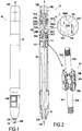
- Figure 1 shows a hand-held device 10, in this example a writing instrument, and more particularly a pen having a retractable ballpoint, comprising a body 12 that extends in an axial direction X.
- the body 12 has a first axial end 12A and a second axial end 12B opposite from the first axial end 12A along the axial direction X.
- a first head 14A is configured to project, in retractable manner, from the first axial end 12A, while a second head 14B is configured to project, in retractable manner, from the second axial end 12B.
- the first head 14A is a ballpoint having thermochromic ink
- the second head 14B is a friction body.
- a friction body is a body configured to be rubbed against a surface, e.g. in order to generate heat, and thereby changing the color of an ink that is thermochromic, i.e. an ink that changes color as a function of the heat to which it is subjected.
- heads of any other kinds could be envisaged for the first head and for the second head.
- the first head 14A projects from the body 12 from the first axial end 12A, while the second head 14B is retracted into the body 12. In other words, the first head 14A is in a utilization position, while the second head 14B is in a retracted position.
- retractable protection 16 configured to protect the first head 14A and to avoid untimely dirtying when the hand-held device 10 is not in use.
- This retractable protection 16 is in the form of a sheath that can be moved axially between a protection position (in dashed lines in Figure 1 ) in which it protects the first head 14A even when it is in its utilization position, and a disengaged position (in continuous lines in Figure 1 ) in which the first head 14A can be used normally while it is in the utilization position.
- This protection 16 includes means known to the person skilled in the art for moving it between its two positions, in particular a button 16A, and for holding it in each of the protection and disengaged positions.
- the hand-held device 10 is described in greater detail below with reference to Figure 2 .
- the hand-held device 10 in this example has a single carriage 14 housed in the body 12 and axially movable within the body 12.
- the carriage 14 carries the first head 14A and the second head 14B, the first head 14A being arranged beside the first axial end 12A, while the second head 14B is arranged beside the second axial end 12B.
- each head is mounted on the carriage 14 by screw-fastening, however any other assembly means known to the person skilled in the art could be envisaged.
- the single carriage 14 comprises two distinct identical parts 14-1 and 14-2 that are assembled together, so as to be mechanically coupled together.
- these two parts 14-1 and 14-2 are coupled to move in translation along the axial direction X.
- Each part 14-1 and 14-2 presents a base 15A extending in the axial direction X and having one of the heads 14A or 14B fastened thereto, and a receptacle 15B configured to receive the ball 18B of the blocking device 18 as described below.
- the concave side of the receptacle 15B has an upside-down V shape, with the ball 18B being capable of going to one side or the other of the V-shape.
- the concave side of the receptacle could have any other shape, e.g. only one branch of the V-shape, or a conical or a frustoconical shape.
- the two parts 14-1 and 14-2 are assembled together by clip fastening via axial tabs extending from the receptacles, so that the receptacle of each part faces the receptacle of the other part along the axial direction X.
- these two parts 14-1 and 14-2 could be assembled together by any other means known to the person skilled in the art.
- the parts 14-1' and 14-2' do not have assembly means and they are independent of each other.
- the hand-held device in the variant of Figure 4 presents a first carriage 14-1' and a second carriage 14-2' that is distinct from the first carriage 14-1'.
- the hand-held device 10 has a single blocking device 18 presenting a single cavity 18A and in this example a single metal ball 18B received in the single cavity 18A. In a variant, there could be two or more balls moving in the single cavity 18A.
- the cavity 18A is arranged between the carriage 14 and the body 12 and it presents a first chamber 18A1, a second chamber 18A2 distinct from the first chamber 18A1, and a passage 18A3 connecting the first and second chambers 18A1 and 18A2 together.
- the portion of the body 12 that receives the carriage 14 is cylindrical, and it presents two diametrically opposite internal radial projections 12C extending towards the inside of the body 12.
- Each projection 12C presents a first axial end wall 12C1, a second axial end wall 12C2 that is opposite in the axial direction from the first axial end wall, and an axial wall 12C3 that extends between the first and second axial end walls 12C1 and 12C2.
- the radial space between the carriage 14 and the radial projections 12C along the axial walls 12C3 forms the passage 18A3 in which the ball 18B moves in order to go from one chamber to the other.
- the space between the first axial end walls 12C1 and the carriage 14 forms the first chamber 18A1, while the space between the second axial end wall 12C2 and the carriage 14 forms the second chamber 18A2.
- the first chamber 18A1 is defined by the first axial end walls 12C1 and the facing walls of the carriage 14, while the second chamber 18A2 is defined by the second axial end walls 12C2 and the facing walls of the carriage 14.
- the first chamber 18A1 is defined by the first axial end walls 12C1 and the walls forming the V-shape of the receptacle 15A of the part 14-1 of the carriage 14.
- the second chamber 18A2 is defined by the second axial end walls 12C2 and the walls forming the V-shape of the receptacle 15A of the part 14-2 of the carriage 14.
- each chamber 18A1 and 18A2 presents an inlet E and an end F, the walls converging from the inlet E towards the end wall F.
- the second axial end walls 12C2 and the walls forming the V-shape of the receptacle facing the second axial end walls 12C2 are inclined at an angle ⁇ relative to each other.
- the angles ⁇ of the first chamber 18A1 and of the second chamber 18A2 may be identical or different.
- the dimensions of the first chamber 18A1 and of the second chamber 18A2 vary as a function of the position of the carriage 14 relative to the body 12.
- the first chamber 18A1 has its maximum dimensions (and its maximum volume), while the second chamber 18A2 is reduced to its minimum and presents zero volume.
- the second chamber 18A2 presents its maximum dimensions (and its maximum volume), while the second chamber 18A1 is reduced to its minimum and presents zero volume.
- the diameter of the ball 18B is greater than the minimum width of the converging portion formed by each chamber when the chamber presents its maximum dimensions, such that the ball 18B cannot escape from the chamber through its end.
- the passage 18A3 is shut beside one or the other of the axial ends of the body by the carriage 14.
- the passage could remain open regardless of the position of the carriage 14 relative to the body 12.
- the hand-held device 10 in this example includes two strikers 20A and 20B.
- the ball 18B is arranged between the two strikers 20A and 20B.
- the carriage 14 is arranged axially between the two strikers 20A and 20B.
- the two strikers 20A and 20B are coupled together in translation in the axial direction X by means of a rod (not shown) connecting them together.
- the strikers 20A and 20B strike the ball 18B via the open end of each chamber 18A1, 18A2.
- Figure 3A shows the hand-held device in the configuration of Figures 1 and 2 , i.e. the first configuration in which the first head 14A is in its utilization position while the second head 14B is in its retracted position.
- the first axial end 12A is below the second axial end 12B.
- the ball 18B is in the first chamber 18A1 and it blocks the carriage 14 axially relative to the body 12. Specifically, the ball 18B is interposed between the carriage 14 and a radial projection 12C of the body 12, without any slack because of the converging shape of the walls of the first chamber 18A1.
- the head when the user seeks to make use of the first head and presses thereon while writing on a substrate, the head is blocked in position by means of the ball 18B, thereby blocking movement of the carriage 14 and thus of the first head 14A along the axial direction X from the first axial end 12A towards the second axial end 12B.
- movement of the carriage 14, and thus of the first head 14A, along the axial direction X from the second axial end 12B towards the first axial end 12A is blocked by a shoulder of the body 12 that is not shown.
- the heads 14A and 14B are blocked respectively in the utilization position and in the retracted position.
- the carriage 14 takes with it the first head 14A from its utilization position to its retracted position and the second head 14B from its retracted position to its utilization position.
- the hand-held device 10 is thus in the second configuration.
- the ball 18B blocking the carriage 14 relative to the body 12
- the user can easily make use of the second head 14B, which remains in position, even when the user presses against a substrate.
- the head is blocked in position by the ball 18B, which blocks movement of the carriage 14 and thus of the second head 14B along the axial direction X from the second axial end 12B towards the first axial end 12A.
- Figure 4 shows a second embodiment of the hand-held device 10', that is identical to the hand-held device 10 of the first embodiment, with the exception of the carriage. Thus, the other elements are not described again and their reference signs remain unchanged.
- the second head 14B is blocked in this position by the ball 18B, while the first head 14A is not blocked in this position, since the first carriage 14-1' is not blocked by the ball (even though the second carriage 14-2' is blocked by the ball 18B). Nevertheless, as a result of gravity, the second head 14B remains in the retracted position.
- the two-carriage variant enables larger areas to be provided for interaction with the ball than in the one-carriage variant (the amplitude of the axial movement needed is smaller with two carriages than one with carriage), which means that the blocking provided by the ball can be more robust.
Landscapes
- Engineering & Computer Science (AREA)
- Theoretical Computer Science (AREA)
- Mechanical Pencils And Projecting And Retracting Systems Therefor, And Multi-System Writing Instruments (AREA)
Description
- The present disclosure relates to a hand-held device having two opposite retractable heads, in which one head is retracted while the other head is in a utilization position, and vice versa. In particular such a hand-held device may be a writing instrument, but not necessarily.
- Writing instruments with two opposite retractable heads are known in which one head is retracted while the other head is in a utilization position, and vice versa. Nevertheless, those retraction mechanisms do not always give full satisfaction, in particular from the point of view of ease of use. There therefore exists a need in this sense.
Further to this general knowledge;DE 17 61 330 A1 discloses a hand-held device having two heads which are not disposed at opposite axial ends of the device body. Said hand-held device includes two carriages with a head locking mechanism. - Additionally, from
FR 984 548 A - An embodiment provides a hand-held device, in particular a writing instrument, comprising a body extending along an axial direction and presenting a first axial end and a second axial end opposite from the first axial end along the axial direction, a single carriage housed in the body and movable in translation along the axial direction relative to the body, the single carriage carrying a first head and a second head opposite from the first head along the axial direction, or a first carriage and a second carriage housed in the body and being movable in translation along the axial direction relative to the body, the first carriage and the second carriage carrying respectively a first head and a second head opposite from the first head along the axial direction, and a single blocking device comprising a single cavity and at least one ball or the equivalent, one ball or the equivalent of the at least one ball or the equivalent blocking the single carriage or the first carriage relative to the body when, relative to the gravity direction, the first axial end is below the second axial end, such that the first head is blocked relative to the body so as to project axially from the first axial end, while the second head is retracted into the body, and one ball or the equivalent of the at least one ball or the equivalent blocking the single carriage or the second carriage when, in the gravity direction, the first axial end is above the second axial end, such that the second head is blocked relative to the body so as to project axially from the second axial end, while the first head is retracted into the body.
- It can be understood that the hand-held device comprises either a single carriage, or else a first carriage and a second carriage. The term "single carriage" is used to mean a single entity capable of travelling as a unit along the axial direction, this entity potentially comprising a single part or a plurality of parts that are coupled to move together axially in translation. The term "a first carriage and a second carriage" designates two carriages that are independent of each other, in particular in the axial direction. Consequently, and unless specified to the contrary, the term "the carriage" is used to cover either "the single carriage" or "the first carriage and the second carriage".
- The term "gravity direction" naturally designates the direction of Newtonian gravitational acceleration created by the Earth, or more generally by the (celestial) body on which the hand-held device is used.
- The term "ball or the equivalent" is used to mean any solid element of any shape that is movable in the cavity and suitable for moving in the cavity under the effect of gravity relative to walls defining the cavity. Consequently, unless mentioned to the contrary, the term "ball" is used to cover "ball or the equivalent". For example, the ball may be made of metal, but not necessarily.
- The hand-held device may include a single ball or a plurality of balls, e.g. two or more balls. Thus, the term "a ball or the equivalent of the at least one ball or the equivalent" covers "the ball or the equivalent" if the blocking device has a single ball or the equivalent or else "one ball or the equivalent from the plurality of balls or the equivalent" if the blocking device has a plurality of balls or the equivalent. Consequently, and unless specified to the contrary, the term "the ball" may cover "at least one ball or the equivalent".
- The single cavity is formed by a single hollow volume, within which the ball can move under the effect of gravity. In other words, the cavity houses the ball. The cavity may be of any shape, which may be simple or complex. For example, the cavity may comprise one or more chambers of dimensions that are fixed or variable, these chambers being connected by passages within which the ball can move in order to pass from one chamber to another. The body and the carriage may form all or some of the walls of the cavity. Thus, the shape and/or the dimensions (or the volume) of the cavity are suitable for changing as a function of the position of the carriage relative to the body.
- For example, the first head and/or the second head may be formed by any hand-held device tool endpiece, e.g. an endpiece comprising a key, a screwdriver, a blade, a punch, a writing tip (felt tip, ball or other point, graphite lead, chalk, or any means suitable for writing on a substrate), a brush, an eraser, a friction body, an active or passive endpiece configured to co-operate with a touch screen, e.g. a capacitive, resistive, inductive, infrared, optical, electrostatic, etc. screen, a cosmetic applicator (brush, pencil, mascara brush, roll-on applicator, lipstick, or any cosmetics applicator means), etc.
- In the variant having a single carriage, as a result of the ball moving within the cavity, when the first axial end is below the second axial end relative to the gravity direction, the single ball or one ball from the plurality of balls co-operates with the single carriage in order to block it relative to the body in the axial direction so that the first head carried by the single carriage extends outside (i.e. at least in part outside) the body from the first axial end. Under such circumstances, the second head is retracted (i.e. fully retracted) in the body. In this variant, since the second head is mounted on the single carriage, it is also blocked in this position.
- Conversely, still as a result of the ball moving within the cavity, when the first axial end is above the second axial end relative to the gravity direction, the single ball or one ball from among the plurality of balls co-operates with the single carriage to block it relative to the body in the axial direction, such that the second head carried by the single carriage extends outside (i.e. at least in part outside) the body from the second axial end. Under such circumstances, the first head is retracted (i.e. fully retracted) in the body. In this variant, since the first head is mounted on the single carriage, it is also blocked in this position.
- In the variant having a first carriage and a second carriage, as a result of the ball moving within the cavity, when the first axial end is below the second axial end relative to the gravity direction, the single ball or one ball among the plurality of balls co-operates with the first carriage to block it relative to the body in the axial direction so that the first head carried by the first carriage extends outside (i.e. at least in part outside) the body from the first axial end. Under such circumstances, the second head is retracted (i.e. fully retracted) in the body. The second carriage carrying the second head may be blocked or not blocked relative to the body.
- Conversely, still as a result of the ball moving within the cavity, when the first axial end is above the second axial end relative to the gravity direction, the single ball or one ball from the plurality of balls co-operates with the second carriage to block it relative to the body in the axial direction such that the second head carried by the second carriage extends outside (i.e. at least in part outside) the body from the second axial end. Under such circumstances, the first head is retracted (i.e. fully retracted) in the body. The first carriage carrying the first head may be blocked or not blocked relative to the body.
- Thus, both in the first variant and in the second variant, it can be understood that the hand-held device takes on a first configuration in which the first head projects from the body from its first end while the second head is retracted in the body, and a second configuration in which the second head projects from the body from the second end while the first head is retracted in the body. In the first configuration, the first head is in a utilization position while the second head is in a retracted position, and conversely, in the second configuration, the second head is in a utilization position while the first head is in a retracted position.
- In order to pass from the first configuration to the second configuration, and vice versa, the first end, which is below the second end in the first configuration, is caused to pass above the second end, and vice versa. During this changeover, as a result of gravity, the ball co-operating with the single carriage or the first carriage in the first configuration becomes disengaged and moves in the cavity so that it no longer co-operates with the single carriage or the first carriage, and a ball, the same ball or another ball, comes to co-operate with the single carriage or the second carriage in the second configuration. In other words, the blocking device is a gravity blocking device that operates automatically and solely as a result of the effects of gravity.
- If there is only one ball, it is this single ball that co-operates with the single carriage or with the first and second carriages. If there is more than one ball, a first ball co-operates with the single carriage or the first carriage in the first configuration, and a second ball, distinct from the first ball, co-operates with the single carriage or with the second carriage in the second configuration, for example.
- Thus, by means of the blocking device having a single cavity and the ball, the head that the user intends to use (i.e. the head pointing downwards relative to the gravity direction) automatically takes up a utilization position and is blocked therein, while the other head automatically takes up a retracted position. This makes the hand-held device particularly easy to use.
- In some embodiments, the single cavity comprises a first chamber and a second chamber distinct from the first chamber, the first chamber being formed between the body and the single carriage or between the body and the first carriage, the second chamber being formed between the body and the single carriage or between the body and the second carriage, one ball or the equivalent of the at least one ball or the equivalent being housed in the first chamber when, in the gravity direction, the first axial end is below the second axial end, and one ball or the equivalent of the at least one ball or the equivalent being housed in the second chamber when, in the gravity direction, the first axial end is above the second axial end.
- The single cavity has two chambers, namely the first chamber and the second chamber, the first chamber being configured to receive the ball that co-operates with the single carriage or with the first carriage in the first configuration, while the second chamber is configured to receive the ball that co-operates with the single carriage or with the second carriage in the second configuration.
- This enables the single cavity to be properly configured relative to the ball as a function of the configuration of the hand-held device. The accuracy of the blocking device is improved, thereby contributing to ease of use.
- In some embodiments, the dimensions (or indeed the volume) of the first chamber and/or the dimensions (or indeed the volume) of the second chamber vary as a function of the position of the single carriage or the positions of the first and second carriages relative to the body.
- For example, the dimensions of the first and/or the second chamber vary so that the space in the first and/or the second chamber that is configured to receive a ball varies between zero space and a non-zero predetermined maximum space.
- This makes it possible to ensure that the blocking device is compact, thereby enabling a hand-held device to be obtained of dimensions that are suitable for being gripped and manipulated easily.
- In some embodiments, each chamber includes an inlet and an end, all or some of the walls of the first chamber and/or all or some of the walls of the second chamber converging from the inlet towards the end.
- It can be understood that the inlet of a chamber is the location through which the ball passes in order to enter and/or leave the chamber, while the ball cannot go beyond the end of the chamber when it is in the chamber. The end may be open or closed. For example, the ball may project in part from the chamber through its end, but cannot escape completely from the chamber via its end. By way of example, the walls of the chamber extending between the inlet and the end of the chamber, referred to as "side" walls, slope relative to one another (i.e. they are not parallel) such that the space between the side walls decreases going from the inlet towards the end. For example, the maximum space between the walls of the chamber at the end of the chamber is less than the diameter of the ball that is configured to be received in said chamber.
- Converging walls make it possible to ensure that the ball that is configured to be received in the chamber co-operates with the walls of the chamber so as to block the carriage axially relative to the body without slack. In other words, the converging walls form a slack take-up system. Thus, when the head carried by the carriage is in the utilization position, there is very little or no axial slack, thereby providing a degree of comfort and a degree of ease in use.
- In some embodiments, the single cavity includes a passage for the at least one ball or the equivalent, the passage extending between the first chamber and the second chamber, the passage being arranged between the body and the single carriage or between the body and the first and second carriages.
- This passage enables the ball to move between the first chamber and the second chamber. It can thus be understood that the passage is located axially between the first chamber and the second chamber. For example, the single cavity comprises solely the first chamber, the second chamber, and the passage connecting the first and second chambers together. For example, the passage is defined solely by the body and by the carriage.
- This serves to provide a blocking device that is compact, thereby providing the hand-held device with dimensions that are appropriate for being gripped and handled easily.
- In some embodiments, the hand-held device comprises at least one striker configured to strike one ball of the at least one ball or the equivalent when, along the gravity direction, the first axial end passes from a position above the second axial end to a position below the second axial end, and/or along the gravity direction when the first axial end passes from a position below the second axial end to a position above the second axial end.
- In other words, the striker is configured to strike the ball that is blocking the carriage relative to the body. For example, the striker may be a flyweight that is movable axially and that is distinct from the at least one ball, or it may be one of the balls of said at least one ball. It can thus be understood that the striker is movable under the effect of gravity. For example, the striker is configured to strike the ball in the axial direction.
- On passing from the first configuration to the second configuration, or vice versa, the striker facilitates disengaging the ball that is blocking the carriage relative to the body. This ensures that the carriage is indeed unblocked and free to move axially within the body. Such a striker serves to avoid any untimely blocking of the carriage within the body and ensures that use of the hand-held device is even easier.
- In some embodiments, the hand-held device includes two strikers and, in the axial direction, the at least one ball or the equivalent is arranged between the two strikers.
- It can thus be understood that a first striker serves to disengage the single ball when it is desired to pass from the first configuration to the second configuration, while the second striker serves to disengage the single ball when it is desired to pass from the second configuration to the first configuration. Naturally, this structure having a single ball and two strikers may be used in hand-held devices having a single carriage or in hand-held devices having two carriages. Such a structure is particularly reliable.
- In some embodiments, the two strikers are coupled together (i.e. they are mechanically coupled together) in the axial direction.
- Coupling together the two strikers increases the weight of the moving assembly that strikes the ball blocking the carriage in position. The percussive effect of the unblocking is thus improved so that handling of the hand-held device is further facilitated.
- The subject matter of the present disclosure and its advantages can be better understood in the light of the following detailed description of various embodiments given as non-limiting examples. The description refers to the sheets of the accompanying figures, in which:
-
Figure 1 shows a first embodiment of the hand-held device; -
Figure 2 is an axial section view of theFigure 1 hand-held device; -
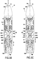
Figures 3A to 3E show various steps for passing from the first configuration to the second configuration; and -
Figure 4 shows a second embodiment of the hand-held device. -
Figure 1 shows a hand-helddevice 10, in this example a writing instrument, and more particularly a pen having a retractable ballpoint, comprising abody 12 that extends in an axial direction X. Thebody 12 has a firstaxial end 12A and a secondaxial end 12B opposite from the firstaxial end 12A along the axial direction X. Afirst head 14A is configured to project, in retractable manner, from the firstaxial end 12A, while asecond head 14B is configured to project, in retractable manner, from the secondaxial end 12B. In this example, thefirst head 14A is a ballpoint having thermochromic ink, while thesecond head 14B is a friction body. It should be recalled that a friction body is a body configured to be rubbed against a surface, e.g. in order to generate heat, and thereby changing the color of an ink that is thermochromic, i.e. an ink that changes color as a function of the heat to which it is subjected. Naturally, heads of any other kinds could be envisaged for the first head and for the second head. InFigure 1 , thefirst head 14A projects from thebody 12 from the firstaxial end 12A, while thesecond head 14B is retracted into thebody 12. In other words, thefirst head 14A is in a utilization position, while thesecond head 14B is in a retracted position. It should be observed that thebody 12 is fitted withretractable protection 16 configured to protect thefirst head 14A and to avoid untimely dirtying when the hand-helddevice 10 is not in use. Thisretractable protection 16 is in the form of a sheath that can be moved axially between a protection position (in dashed lines inFigure 1 ) in which it protects thefirst head 14A even when it is in its utilization position, and a disengaged position (in continuous lines inFigure 1 ) in which thefirst head 14A can be used normally while it is in the utilization position. Thisprotection 16 includes means known to the person skilled in the art for moving it between its two positions, in particular abutton 16A, and for holding it in each of the protection and disengaged positions. - The hand-held
device 10 is described in greater detail below with reference toFigure 2 . The hand-helddevice 10 in this example has asingle carriage 14 housed in thebody 12 and axially movable within thebody 12. Thecarriage 14 carries thefirst head 14A and thesecond head 14B, thefirst head 14A being arranged beside the firstaxial end 12A, while thesecond head 14B is arranged beside the secondaxial end 12B. In this example, each head is mounted on thecarriage 14 by screw-fastening, however any other assembly means known to the person skilled in the art could be envisaged. - In this example, the
single carriage 14 comprises two distinct identical parts 14-1 and 14-2 that are assembled together, so as to be mechanically coupled together. In particular, these two parts 14-1 and 14-2 are coupled to move in translation along the axial direction X. Each part 14-1 and 14-2 presents abase 15A extending in the axial direction X and having one of theheads receptacle 15B configured to receive theball 18B of the blockingdevice 18 as described below. In this example, the concave side of thereceptacle 15B has an upside-down V shape, with theball 18B being capable of going to one side or the other of the V-shape. Naturally, in a variant, the concave side of the receptacle could have any other shape, e.g. only one branch of the V-shape, or a conical or a frustoconical shape. - In this example, the two parts 14-1 and 14-2 are assembled together by clip fastening via axial tabs extending from the receptacles, so that the receptacle of each part faces the receptacle of the other part along the axial direction X. Naturally, these two parts 14-1 and 14-2 could be assembled together by any other means known to the person skilled in the art. In a variant that is shown in
Figure 4 , the parts 14-1' and 14-2' do not have assembly means and they are independent of each other. Thus, the hand-held device in the variant ofFigure 4 presents a first carriage 14-1' and a second carriage 14-2' that is distinct from the first carriage 14-1'. - The hand-held
device 10 has asingle blocking device 18 presenting asingle cavity 18A and in this example asingle metal ball 18B received in thesingle cavity 18A. In a variant, there could be two or more balls moving in thesingle cavity 18A. - The
cavity 18A is arranged between thecarriage 14 and thebody 12 and it presents a first chamber 18A1, a second chamber 18A2 distinct from the first chamber 18A1, and a passage 18A3 connecting the first and second chambers 18A1 and 18A2 together. - The portion of the
body 12 that receives thecarriage 14 is cylindrical, and it presents two diametrically opposite internalradial projections 12C extending towards the inside of thebody 12. Eachprojection 12C presents a first axial end wall 12C1, a second axial end wall 12C2 that is opposite in the axial direction from the first axial end wall, and an axial wall 12C3 that extends between the first and second axial end walls 12C1 and 12C2. The radial space between thecarriage 14 and theradial projections 12C along the axial walls 12C3 forms the passage 18A3 in which theball 18B moves in order to go from one chamber to the other. The space between the first axial end walls 12C1 and thecarriage 14 forms the first chamber 18A1, while the space between the second axial end wall 12C2 and thecarriage 14 forms the second chamber 18A2. In other words, the first chamber 18A1 is defined by the first axial end walls 12C1 and the facing walls of thecarriage 14, while the second chamber 18A2 is defined by the second axial end walls 12C2 and the facing walls of thecarriage 14. More particularly, in this example, the first chamber 18A1 is defined by the first axial end walls 12C1 and the walls forming the V-shape of thereceptacle 15A of the part 14-1 of thecarriage 14. In similar manner, in this example, the second chamber 18A2 is defined by the second axial end walls 12C2 and the walls forming the V-shape of thereceptacle 15A of the part 14-2 of thecarriage 14. - The walls of the V-shape of the
receptacle 15B are not parallel to the axial end walls 14A1 and 14A2. In other words, the walls of the first and second chambers converge. More precisely, each chamber 18A1 and 18A2 presents an inlet E and an end F, the walls converging from the inlet E towards the end wall F. In this example, when considered in section along the axial direction X, the first axial end walls 12C1 and the walls forming the V-shape of the receptacle facing the first axial end walls 12C1 are inclined relative to one another at an angle α (see enlargement inFigure 2 ). In this example, α = 3° (three degrees of angle). Likewise, in this example, when considered in section along the axial direction X, the second axial end walls 12C2 and the walls forming the V-shape of the receptacle facing the second axial end walls 12C2 are inclined at an angle α relative to each other. Naturally, the angles α of the first chamber 18A1 and of the second chamber 18A2 may be identical or different. - Since the
carriage 14 is movable along the axial direction X relative to thebody 12, the dimensions of the first chamber 18A1 and of the second chamber 18A2 vary as a function of the position of thecarriage 14 relative to thebody 12. In particular, inFigure 2 , the first chamber 18A1 has its maximum dimensions (and its maximum volume), while the second chamber 18A2 is reduced to its minimum and presents zero volume. Conversely, inFigure 3E , the second chamber 18A2 presents its maximum dimensions (and its maximum volume), while the second chamber 18A1 is reduced to its minimum and presents zero volume. The diameter of theball 18B is greater than the minimum width of the converging portion formed by each chamber when the chamber presents its maximum dimensions, such that theball 18B cannot escape from the chamber through its end. Furthermore, in this example, depending on the position of thecarriage 14 relative to thebody 12, the passage 18A3 is shut beside one or the other of the axial ends of the body by thecarriage 14. Naturally, depending on the variant, the passage could remain open regardless of the position of thecarriage 14 relative to thebody 12. - The hand-held
device 10 in this example includes twostrikers ball 18B is arranged between the twostrikers carriage 14 is arranged axially between the twostrikers strikers strikers ball 18B via the open end of each chamber 18A1, 18A2. - The operation of the hand-held
device 10 is described below with reference toFigures 3A to 3E . -
Figure 3A shows the hand-held device in the configuration ofFigures 1 and 2 , i.e. the first configuration in which thefirst head 14A is in its utilization position while thesecond head 14B is in its retracted position. In this configuration, considered along the gravity direction G, the firstaxial end 12A is below the secondaxial end 12B. Theball 18B is in the first chamber 18A1 and it blocks thecarriage 14 axially relative to thebody 12. Specifically, theball 18B is interposed between thecarriage 14 and aradial projection 12C of thebody 12, without any slack because of the converging shape of the walls of the first chamber 18A1. Thus, when the user seeks to make use of the first head and presses thereon while writing on a substrate, the head is blocked in position by means of theball 18B, thereby blocking movement of thecarriage 14 and thus of thefirst head 14A along the axial direction X from the firstaxial end 12A towards the secondaxial end 12B. Naturally, movement of thecarriage 14, and thus of thefirst head 14A, along the axial direction X from the secondaxial end 12B towards the firstaxial end 12A is blocked by a shoulder of thebody 12 that is not shown. With thecarriage 14 blocked relative to thebody 12 and carrying the first and second heads, theheads - In order to go to the second configuration in which the
first head 14A is in the retracted position and thesecond head 14B is in the utilization position, it suffices to cause the firstaxial end 12A to pass above the secondaxial end 12B relative to the gravity direction G, as shown inFigure 3B . In this position, as a result of gravity, thestriker 20A strikes theball 18B, thereby having the effect of assisting it to become disengaged from the walls of the first chamber 18A1. In a variant without a striker theball 18B disengages on its own from the walls of the first chamber 18A1 under the effect of gravity with this being made possible by its relatively large weight, theball 18B in this example being made of metal. - When the
ball 18B disengages, it moves under the effect of gravity, and it leaves the first chamber 18A1 to go into the passage 18A3, as shown inFigure 3C . As a result, thecarriage 14 becomes free to move along the axial direction X relative to thebody 12, since it is no longer blocked by theball 18B. - Under the effect of gravity, the
carriage 14 moves towards the secondaxial end 12B, as shown inFigure 3D . It should be observed that during this movement, the dimensions of the first chamber 18A1 become smaller until the volume of the first chamber 18A1 is zero, while the volume of the second chamber 18A2 becomes non-zero and increases progressively. - In
Figure 3E , the volume of the second chamber 18A2 is at a maximum, and theball 18B, still under the effect of gravity, has left the passage 18A3 and penetrated into the second chamber 18A2 in order to become wedged, without slack, between the converging walls of the second chamber 18A2. - During this movement, the
carriage 14 takes with it thefirst head 14A from its utilization position to its retracted position and thesecond head 14B from its retracted position to its utilization position. The hand-helddevice 10 is thus in the second configuration. With theball 18B blocking thecarriage 14 relative to thebody 12, the user can easily make use of thesecond head 14B, which remains in position, even when the user presses against a substrate. In other words, when the user seeks to make use of thesecond head 14B, and presses down against a substrate, the head is blocked in position by theball 18B, which blocks movement of thecarriage 14 and thus of thesecond head 14B along the axial direction X from the secondaxial end 12B towards the firstaxial end 12A. Naturally, movement of thecarriage 14, and thus of thesecond head 14B, along the axial direction X from the firstaxial end 12A towards the secondaxial end 12B is blocked by a shoulder of the body 12 (not shown). With thecarriage 14 blocked relative to thebody 12 and carrying the first and second heads, theheads - In order to return to the first configuration, it suffices to make the opposite movement, i.e. to place the first
axial end 12A below the secondaxial end 12B in the gravity direction G. Under the effect of gravity, thestriker 20B then strikes theball 18B, which disengages from the second chamber 18A2, and releases thecarriage 14, which moves axially, taking with it theheads carriage 14 relative to thebody 12. This is a return to the first configuration shown inFigure 3A . -
Figure 4 shows a second embodiment of the hand-held device 10', that is identical to the hand-helddevice 10 of the first embodiment, with the exception of the carriage. Thus, the other elements are not described again and their reference signs remain unchanged. - In this second embodiment, there is not a single carriage, but rather a first carriage 14-1' and a second carriage 14-2' carrying respectively the
first head 14A and thesecond head 14B. Thus, in the first configuration, when thefirst head 14A is in the utilization position and thesecond head 14B is in the retracted position, thefirst head 14A is blocked in this position by theball 18B, while thesecond head 14B is not blocked in this position, since the second carriage 14-2' is not blocked by theball 18B (whereas the first carriage 14-1' is blocked by theball 18B). Nevertheless, as a result of gravity, thesecond head 14B remains in the retracted position. Conversely, in the second configuration in which thefirst head 14A is in the retracted position and thesecond head 14B is in the utilization position, thesecond head 14B is blocked in this position by theball 18B, while thefirst head 14A is not blocked in this position, since the first carriage 14-1' is not blocked by the ball (even though the second carriage 14-2' is blocked by theball 18B). Nevertheless, as a result of gravity, thesecond head 14B remains in the retracted position. - It should be observed that deciding whether to design the hand-held device with one carriage or with two carriages may depend on requirements concerning size and/or the strength of the blocking of the carriage by the ball, but not necessarily. Specifically, the two-carriage variant enables larger areas to be provided for interaction with the ball than in the one-carriage variant (the amplitude of the axial movement needed is smaller with two carriages than one with carriage), which means that the blocking provided by the ball can be more robust.
- Although the present invention is described with reference to specific embodiments, it is clear that modifications and changes may be carried out thereon without going beyond the invention as defined by the claims. In particular, individual characteristics of the various embodiments shown and/or mentioned may be combined in additional embodiments. Consequently, the description and the drawings should be considered in a sense that is illustrative rather than restrictive.
Claims (8)
- A hand-held device, in particular a writing instrument, comprising a body (12) extending along an axial direction (X) and presenting a first axial end (12A) and a second axial end (12B) opposite from the first axial end (12A) along the axial direction (X), a single carriage (14) housed in the body (12) and movable in translation along the axial direction (X) relative to the body (12), the single carriage (14) carrying a first head (14A) and a second head (14B) opposite from the first head (14A) along the axial direction (X), or a first carriage (14-1') and a second carriage (14-2') housed in the body (12) and being movable in translation along the axial direction (X) relative to the body (12), the first carriage (14-1') and the second carriage (14-2') carrying respectively a first head (14A) and a second head (14B) opposite from the first head (14A) along the axial direction (X), and a single blocking device (18) comprising a single cavity (18A) and at least one ball or the equivalent (18B), one ball or the equivalent (18B) of the at least one ball or the equivalent blocking the single carriage (14) or the first carriage (14-1') relative to the body (12) when, relative to the gravity direction (G), the first axial end (12A) is below the second axial end (12B), such that the first head (14A) is blocked relative to the body (12) so as to project axially from the first axial end (12A), while the second head (14B) is retracted into the body (12), and one ball or the equivalent (18B) of the at least one ball or the equivalent blocking the single carriage (14) or the second carriage (14-2') when, in the gravity direction (G), the first axial end (12A) is above the second axial end (12B), such that the second head (14B) is blocked relative to the body (12) so as to project axially from the second axial end (12B), while the first head (14A) is retracted into the body (12).
- A hand-held device according to claim 1, wherein the single cavity (18A) comprises a first chamber (18A1) and a second chamber (18A2) distinct from the first chamber (18A1), the first chamber (18A1) being formed between the body (12) and the single carriage (14) or between the body (12) and the first carriage (14-1'), the second chamber (18A2) being formed between the body (12) and the single carriage (14) or between the body (12) and the second carriage (14-2'), one ball or the equivalent (18B) of the at least one ball or the equivalent being housed in the first chamber (18A1) when, in the gravity direction (G), the first axial end (12A) is below the second axial end (12B), and one ball or the equivalent (18B) of the at least one ball or the equivalent being housed in the second chamber (18A2) when, in the gravity direction (G), the first axial end (12A) is above the second axial end (12B).
- A hand-held device according to claim 2, wherein the dimensions of the first chamber (18A1) and/or the dimensions of the second chamber (18A2) vary as a function of the position of the single carriage (14) or the positions of the first and second carriages (14-1', 14-2') relative to the body (12).
- A hand-held device according to claim 2 or claim 3, wherein each chamber (18A1, 18A2) includes an inlet (E) and an end (F), all or some of the walls of the first chamber (18A1) and/or all or some of the walls of the second chamber (18A2) converging from the inlet (E) towards the end (F).
- A hand-held device according to any one of claims 2 to 4, wherein the single cavity (18A) includes a passage (18A3) for the at least one ball or the equivalent (18B), the passage extending between the first chamber (18A1) and the second chamber (18A2), the passage (18A3) being arranged between the body (12) and the single carriage (14) or between the body (12) and the first and second carriages (14-1', 14-2').
- A hand-held device according to any one of claims 1 to 5, including at least one striker (20A, 20B) configured to strike one ball or the equivalent (18B) of the at least one ball or the equivalent when, along the gravity direction (G), the first axial end (12A) passes from a position above the second axial end (12B) to a position below the second axial end (12B), and/or along the gravity direction (G) when the first axial end (12A) passes from a position below the second axial end (12B) to a position above the second axial end (12B).
- A hand-held device according to claim 6, including two strikers (20A, 20B) and, in the axial direction (X), the at least one ball or the equivalent (18B) is arranged between the two strikers (20A, 20B).
- A hand-held device according to claim 7, wherein the two strikers (20A, 20B) are coupled together in the axial direction (X).
Applications Claiming Priority (1)
| Application Number | Priority Date | Filing Date | Title |
|---|---|---|---|
| FR1853471A FR3080326B1 (en) | 2018-04-19 | 2018-04-19 | MANUAL DEVICE, ESPECIALLY A WRITING INSTRUMENT, COMPRISING TWO RETRACTABLE HEADS |
Publications (2)
| Publication Number | Publication Date |
|---|---|
| EP3556569A1 EP3556569A1 (en) | 2019-10-23 |
| EP3556569B1 true EP3556569B1 (en) | 2021-01-20 |
Family
ID=62751124
Family Applications (1)
| Application Number | Title | Priority Date | Filing Date |
|---|---|---|---|
| EP19170276.0A Not-in-force EP3556569B1 (en) | 2018-04-19 | 2019-04-18 | A hand-held device, in particular a writing instrument, having two retractable heads |
Country Status (3)
| Country | Link |
|---|---|
| US (1) | US10766297B2 (en) |
| EP (1) | EP3556569B1 (en) |
| FR (1) | FR3080326B1 (en) |
Families Citing this family (4)
| Publication number | Priority date | Publication date | Assignee | Title |
|---|---|---|---|---|
| FR3055577B1 (en) * | 2016-09-07 | 2018-09-28 | SOCIéTé BIC | MANUAL DEVICE, IN PARTICULAR A WRITING INSTRUMENT, WITH TWO RETRACTABLE HEADS CARRIED BY A SINGLE TROLLEY |
| FR3075097B1 (en) * | 2017-12-20 | 2020-01-03 | Societe Bic | MULTIPURPOSE WRITING INSTRUMENT INCLUDING A PORTEMINE SYSTEM |
| CN211354223U (en) * | 2019-09-30 | 2020-08-28 | 洽兴包装工业(中国)有限公司 | Cosmetic bottle with replaceable internal component |
| EP4159468A1 (en) * | 2021-09-30 | 2023-04-05 | BIC Violex Single Member S.A. | Writing instruments |
Family Cites Families (4)
| Publication number | Priority date | Publication date | Assignee | Title |
|---|---|---|---|---|
| FR984548A (en) * | 1949-02-11 | 1951-07-06 | Advanced ballpoint pen | |
| NL205053A (en) * | 1955-03-04 | |||
| GB2381243B (en) * | 2003-02-18 | 2003-11-05 | Geoffrey Peter Mayne | Writing instrument |
| FR3053924B1 (en) * | 2016-07-12 | 2019-07-12 | Societe Bic | MANUAL DEVICE, IN PARTICULAR A WRITING INSTRUMENT, EQUIPPED WITH A LOCKING DEVICE |
-
2018
- 2018-04-19 FR FR1853471A patent/FR3080326B1/en not_active Expired - Fee Related
-
2019
- 2019-04-18 EP EP19170276.0A patent/EP3556569B1/en not_active Not-in-force
- 2019-04-19 US US16/388,963 patent/US10766297B2/en active Active
Non-Patent Citations (1)
| Title |
|---|
| None * |
Also Published As
| Publication number | Publication date |
|---|---|
| FR3080326A1 (en) | 2019-10-25 |
| FR3080326B1 (en) | 2020-05-01 |
| US20190322121A1 (en) | 2019-10-24 |
| US10766297B2 (en) | 2020-09-08 |
| EP3556569A1 (en) | 2019-10-23 |
Similar Documents
| Publication | Publication Date | Title |
|---|---|---|
| EP3556569B1 (en) | A hand-held device, in particular a writing instrument, having two retractable heads | |
| US4969764A (en) | Capless retractable marking pen | |
| US4711592A (en) | Capless retractable marking pen | |
| JP2020175636A (en) | Rotating locking pen | |
| US6981812B1 (en) | Opening and closing device for capless retractable marker pen | |
| JP2008260291A (en) | Writing instrument | |
| EP2812192B1 (en) | Nib assembly having a double wall and writing instrument comprising same | |
| EP3575103A1 (en) | Multifunctional writing instrument | |
| KR102536678B1 (en) | Intrusive writing instruments and multi-reed writing instruments | |
| US10807405B2 (en) | Hand-held device, in particular a writing instrument, provided with a blocking device | |
| JP2013006317A (en) | Multicore writing instrument | |
| US4951856A (en) | Pen pack | |
| US20230302843A1 (en) | Writing instrument and method thereof | |
| US20210078353A1 (en) | Multi-function writing instrument comprising a lead-holder system | |
| US20190092085A1 (en) | Writing utensil with telescoping cap | |
| JP6530095B2 (en) | Writing instrument | |
| WO2019197544A1 (en) | A manual device with two heads | |
| CN110370841A (en) | Propelling pencil with shield core function | |
| CN203391513U (en) | Anti-fall pen | |
| Bank et al. | Deep impact- 19 gigajoules can make quite an impression | |
| JP2020116957A (en) | Writing instrument | |
| US11766886B2 (en) | Writing instrument | |
| WO2020222141A1 (en) | Retractable element for a writing implement | |
| JP6692964B2 (en) | Writing instrument | |
| EP4159468A1 (en) | Writing instruments |
Legal Events
| Date | Code | Title | Description |
|---|---|---|---|
| PUAI | Public reference made under article 153(3) epc to a published international application that has entered the european phase |
Free format text: ORIGINAL CODE: 0009012 |
|
| STAA | Information on the status of an ep patent application or granted ep patent |
Free format text: STATUS: THE APPLICATION HAS BEEN PUBLISHED |
|
| AK | Designated contracting states |
Kind code of ref document: A1 Designated state(s): AL AT BE BG CH CY CZ DE DK EE ES FI FR GB GR HR HU IE IS IT LI LT LU LV MC MK MT NL NO PL PT RO RS SE SI SK SM TR |
|
| AX | Request for extension of the european patent |
Extension state: BA ME |
|
| STAA | Information on the status of an ep patent application or granted ep patent |
Free format text: STATUS: REQUEST FOR EXAMINATION WAS MADE |
|
| 17P | Request for examination filed |
Effective date: 20200409 |
|
| RBV | Designated contracting states (corrected) |
Designated state(s): AL AT BE BG CH CY CZ DE DK EE ES FI FR GB GR HR HU IE IS IT LI LT LU LV MC MK MT NL NO PL PT RO RS SE SI SK SM TR |
|
| GRAP | Despatch of communication of intention to grant a patent |
Free format text: ORIGINAL CODE: EPIDOSNIGR1 |
|
| STAA | Information on the status of an ep patent application or granted ep patent |
Free format text: STATUS: GRANT OF PATENT IS INTENDED |
|
| INTG | Intention to grant announced |
Effective date: 20200824 |
|
| GRAS | Grant fee paid |
Free format text: ORIGINAL CODE: EPIDOSNIGR3 |
|
| GRAA | (expected) grant |
Free format text: ORIGINAL CODE: 0009210 |
|
| STAA | Information on the status of an ep patent application or granted ep patent |
Free format text: STATUS: THE PATENT HAS BEEN GRANTED |
|
| AK | Designated contracting states |
Kind code of ref document: B1 Designated state(s): AL AT BE BG CH CY CZ DE DK EE ES FI FR GB GR HR HU IE IS IT LI LT LU LV MC MK MT NL NO PL PT RO RS SE SI SK SM TR |
|
| REG | Reference to a national code |
Ref country code: GB Ref legal event code: FG4D |
|
| REG | Reference to a national code |
Ref country code: CH Ref legal event code: EP |
|
| REG | Reference to a national code |
Ref country code: AT Ref legal event code: REF Ref document number: 1356058 Country of ref document: AT Kind code of ref document: T Effective date: 20210215 |
|
| REG | Reference to a national code |
Ref country code: IE Ref legal event code: FG4D |
|
| REG | Reference to a national code |
Ref country code: DE Ref legal event code: R096 Ref document number: 602019002240 Country of ref document: DE |
|
| REG | Reference to a national code |
Ref country code: NL Ref legal event code: MP Effective date: 20210120 |
|
| REG | Reference to a national code |
Ref country code: LT Ref legal event code: MG9D |
|
| REG | Reference to a national code |
Ref country code: AT Ref legal event code: MK05 Ref document number: 1356058 Country of ref document: AT Kind code of ref document: T Effective date: 20210120 |
|
| PG25 | Lapsed in a contracting state [announced via postgrant information from national office to epo] |
Ref country code: BG Free format text: LAPSE BECAUSE OF FAILURE TO SUBMIT A TRANSLATION OF THE DESCRIPTION OR TO PAY THE FEE WITHIN THE PRESCRIBED TIME-LIMIT Effective date: 20210420 Ref country code: HR Free format text: LAPSE BECAUSE OF FAILURE TO SUBMIT A TRANSLATION OF THE DESCRIPTION OR TO PAY THE FEE WITHIN THE PRESCRIBED TIME-LIMIT Effective date: 20210120 Ref country code: FI Free format text: LAPSE BECAUSE OF FAILURE TO SUBMIT A TRANSLATION OF THE DESCRIPTION OR TO PAY THE FEE WITHIN THE PRESCRIBED TIME-LIMIT Effective date: 20210120 Ref country code: GR Free format text: LAPSE BECAUSE OF FAILURE TO SUBMIT A TRANSLATION OF THE DESCRIPTION OR TO PAY THE FEE WITHIN THE PRESCRIBED TIME-LIMIT Effective date: 20210421 Ref country code: LT Free format text: LAPSE BECAUSE OF FAILURE TO SUBMIT A TRANSLATION OF THE DESCRIPTION OR TO PAY THE FEE WITHIN THE PRESCRIBED TIME-LIMIT Effective date: 20210120 Ref country code: PT Free format text: LAPSE BECAUSE OF FAILURE TO SUBMIT A TRANSLATION OF THE DESCRIPTION OR TO PAY THE FEE WITHIN THE PRESCRIBED TIME-LIMIT Effective date: 20210520 Ref country code: NO Free format text: LAPSE BECAUSE OF FAILURE TO SUBMIT A TRANSLATION OF THE DESCRIPTION OR TO PAY THE FEE WITHIN THE PRESCRIBED TIME-LIMIT Effective date: 20210420 |
|
| PG25 | Lapsed in a contracting state [announced via postgrant information from national office to epo] |
Ref country code: LV Free format text: LAPSE BECAUSE OF FAILURE TO SUBMIT A TRANSLATION OF THE DESCRIPTION OR TO PAY THE FEE WITHIN THE PRESCRIBED TIME-LIMIT Effective date: 20210120 Ref country code: RS Free format text: LAPSE BECAUSE OF FAILURE TO SUBMIT A TRANSLATION OF THE DESCRIPTION OR TO PAY THE FEE WITHIN THE PRESCRIBED TIME-LIMIT Effective date: 20210120 Ref country code: PL Free format text: LAPSE BECAUSE OF FAILURE TO SUBMIT A TRANSLATION OF THE DESCRIPTION OR TO PAY THE FEE WITHIN THE PRESCRIBED TIME-LIMIT Effective date: 20210120 Ref country code: AT Free format text: LAPSE BECAUSE OF FAILURE TO SUBMIT A TRANSLATION OF THE DESCRIPTION OR TO PAY THE FEE WITHIN THE PRESCRIBED TIME-LIMIT Effective date: 20210120 Ref country code: SE Free format text: LAPSE BECAUSE OF FAILURE TO SUBMIT A TRANSLATION OF THE DESCRIPTION OR TO PAY THE FEE WITHIN THE PRESCRIBED TIME-LIMIT Effective date: 20210120 |
|
| PG25 | Lapsed in a contracting state [announced via postgrant information from national office to epo] |
Ref country code: IS Free format text: LAPSE BECAUSE OF FAILURE TO SUBMIT A TRANSLATION OF THE DESCRIPTION OR TO PAY THE FEE WITHIN THE PRESCRIBED TIME-LIMIT Effective date: 20210520 |
|
| REG | Reference to a national code |
Ref country code: DE Ref legal event code: R097 Ref document number: 602019002240 Country of ref document: DE |
|
| PG25 | Lapsed in a contracting state [announced via postgrant information from national office to epo] |
Ref country code: CZ Free format text: LAPSE BECAUSE OF FAILURE TO SUBMIT A TRANSLATION OF THE DESCRIPTION OR TO PAY THE FEE WITHIN THE PRESCRIBED TIME-LIMIT Effective date: 20210120 Ref country code: EE Free format text: LAPSE BECAUSE OF FAILURE TO SUBMIT A TRANSLATION OF THE DESCRIPTION OR TO PAY THE FEE WITHIN THE PRESCRIBED TIME-LIMIT Effective date: 20210120 Ref country code: SM Free format text: LAPSE BECAUSE OF FAILURE TO SUBMIT A TRANSLATION OF THE DESCRIPTION OR TO PAY THE FEE WITHIN THE PRESCRIBED TIME-LIMIT Effective date: 20210120 |
|
| PLBE | No opposition filed within time limit |
Free format text: ORIGINAL CODE: 0009261 |
|
| STAA | Information on the status of an ep patent application or granted ep patent |
Free format text: STATUS: NO OPPOSITION FILED WITHIN TIME LIMIT |
|
| PG25 | Lapsed in a contracting state [announced via postgrant information from national office to epo] |
Ref country code: DK Free format text: LAPSE BECAUSE OF FAILURE TO SUBMIT A TRANSLATION OF THE DESCRIPTION OR TO PAY THE FEE WITHIN THE PRESCRIBED TIME-LIMIT Effective date: 20210120 Ref country code: SK Free format text: LAPSE BECAUSE OF FAILURE TO SUBMIT A TRANSLATION OF THE DESCRIPTION OR TO PAY THE FEE WITHIN THE PRESCRIBED TIME-LIMIT Effective date: 20210120 Ref country code: RO Free format text: LAPSE BECAUSE OF FAILURE TO SUBMIT A TRANSLATION OF THE DESCRIPTION OR TO PAY THE FEE WITHIN THE PRESCRIBED TIME-LIMIT Effective date: 20210120 Ref country code: MC Free format text: LAPSE BECAUSE OF FAILURE TO SUBMIT A TRANSLATION OF THE DESCRIPTION OR TO PAY THE FEE WITHIN THE PRESCRIBED TIME-LIMIT Effective date: 20210120 |
|
| 26N | No opposition filed |
Effective date: 20211021 |
|
| PG25 | Lapsed in a contracting state [announced via postgrant information from national office to epo] |
Ref country code: LU Free format text: LAPSE BECAUSE OF NON-PAYMENT OF DUE FEES Effective date: 20210418 |
|
| REG | Reference to a national code |
Ref country code: BE Ref legal event code: MM Effective date: 20210430 |
|
| PG25 | Lapsed in a contracting state [announced via postgrant information from national office to epo] |
Ref country code: AL Free format text: LAPSE BECAUSE OF FAILURE TO SUBMIT A TRANSLATION OF THE DESCRIPTION OR TO PAY THE FEE WITHIN THE PRESCRIBED TIME-LIMIT Effective date: 20210120 Ref country code: ES Free format text: LAPSE BECAUSE OF FAILURE TO SUBMIT A TRANSLATION OF THE DESCRIPTION OR TO PAY THE FEE WITHIN THE PRESCRIBED TIME-LIMIT Effective date: 20210120 |
|
| PG25 | Lapsed in a contracting state [announced via postgrant information from national office to epo] |
Ref country code: SI Free format text: LAPSE BECAUSE OF FAILURE TO SUBMIT A TRANSLATION OF THE DESCRIPTION OR TO PAY THE FEE WITHIN THE PRESCRIBED TIME-LIMIT Effective date: 20210120 |
|
| PG25 | Lapsed in a contracting state [announced via postgrant information from national office to epo] |
Ref country code: IT Free format text: LAPSE BECAUSE OF FAILURE TO SUBMIT A TRANSLATION OF THE DESCRIPTION OR TO PAY THE FEE WITHIN THE PRESCRIBED TIME-LIMIT Effective date: 20210120 Ref country code: IE Free format text: LAPSE BECAUSE OF NON-PAYMENT OF DUE FEES Effective date: 20210418 |
|
| PG25 | Lapsed in a contracting state [announced via postgrant information from national office to epo] |
Ref country code: IS Free format text: LAPSE BECAUSE OF FAILURE TO SUBMIT A TRANSLATION OF THE DESCRIPTION OR TO PAY THE FEE WITHIN THE PRESCRIBED TIME-LIMIT Effective date: 20210520 Ref country code: FR Free format text: LAPSE BECAUSE OF NON-PAYMENT OF DUE FEES Effective date: 20210430 |
|
| PG25 | Lapsed in a contracting state [announced via postgrant information from national office to epo] |
Ref country code: BE Free format text: LAPSE BECAUSE OF NON-PAYMENT OF DUE FEES Effective date: 20210430 |
|
| REG | Reference to a national code |
Ref country code: CH Ref legal event code: PL |
|
| PG25 | Lapsed in a contracting state [announced via postgrant information from national office to epo] |
Ref country code: LI Free format text: LAPSE BECAUSE OF NON-PAYMENT OF DUE FEES Effective date: 20220430 Ref country code: CH Free format text: LAPSE BECAUSE OF NON-PAYMENT OF DUE FEES Effective date: 20220430 |
|
| PG25 | Lapsed in a contracting state [announced via postgrant information from national office to epo] |
Ref country code: NL Free format text: LAPSE BECAUSE OF NON-PAYMENT OF DUE FEES Effective date: 20210120 Ref country code: CY Free format text: LAPSE BECAUSE OF FAILURE TO SUBMIT A TRANSLATION OF THE DESCRIPTION OR TO PAY THE FEE WITHIN THE PRESCRIBED TIME-LIMIT Effective date: 20210120 |
|
| PG25 | Lapsed in a contracting state [announced via postgrant information from national office to epo] |
Ref country code: HU Free format text: LAPSE BECAUSE OF FAILURE TO SUBMIT A TRANSLATION OF THE DESCRIPTION OR TO PAY THE FEE WITHIN THE PRESCRIBED TIME-LIMIT; INVALID AB INITIO Effective date: 20190418 |
|
| PG25 | Lapsed in a contracting state [announced via postgrant information from national office to epo] |
Ref country code: MK Free format text: LAPSE BECAUSE OF FAILURE TO SUBMIT A TRANSLATION OF THE DESCRIPTION OR TO PAY THE FEE WITHIN THE PRESCRIBED TIME-LIMIT Effective date: 20210120 |
|
| PGFP | Annual fee paid to national office [announced via postgrant information from national office to epo] |
Ref country code: GB Payment date: 20240320 Year of fee payment: 6 |
|
| PGFP | Annual fee paid to national office [announced via postgrant information from national office to epo] |
Ref country code: DE Payment date: 20240320 Year of fee payment: 6 |
|
| PG25 | Lapsed in a contracting state [announced via postgrant information from national office to epo] |
Ref country code: MT Free format text: LAPSE BECAUSE OF FAILURE TO SUBMIT A TRANSLATION OF THE DESCRIPTION OR TO PAY THE FEE WITHIN THE PRESCRIBED TIME-LIMIT Effective date: 20210120 |
|
| REG | Reference to a national code |
Ref country code: DE Ref legal event code: R119 Ref document number: 602019002240 Country of ref document: DE |
|
| PG25 | Lapsed in a contracting state [announced via postgrant information from national office to epo] |
Ref country code: TR Free format text: LAPSE BECAUSE OF FAILURE TO SUBMIT A TRANSLATION OF THE DESCRIPTION OR TO PAY THE FEE WITHIN THE PRESCRIBED TIME-LIMIT Effective date: 20210120 |
|
| GBPC | Gb: european patent ceased through non-payment of renewal fee |
Effective date: 20250418 |
|
| PG25 | Lapsed in a contracting state [announced via postgrant information from national office to epo] |
Ref country code: DE Free format text: LAPSE BECAUSE OF NON-PAYMENT OF DUE FEES Effective date: 20251104 |
|
| PG25 | Lapsed in a contracting state [announced via postgrant information from national office to epo] |
Ref country code: GB Free format text: LAPSE BECAUSE OF NON-PAYMENT OF DUE FEES Effective date: 20250418 |