EP3556521B1 - Brake path monitoring of a kinematic - Google Patents
Brake path monitoring of a kinematic Download PDFInfo
- Publication number
- EP3556521B1 EP3556521B1 EP18168059.6A EP18168059A EP3556521B1 EP 3556521 B1 EP3556521 B1 EP 3556521B1 EP 18168059 A EP18168059 A EP 18168059A EP 3556521 B1 EP3556521 B1 EP 3556521B1
- Authority
- EP
- European Patent Office
- Prior art keywords
- braking
- point
- envelope
- virtual end
- virtual
- Prior art date
- Legal status (The legal status is an assumption and is not a legal conclusion. Google has not performed a legal analysis and makes no representation as to the accuracy of the status listed.)
- Active
Links
- 238000012544 monitoring process Methods 0.000 title description 3
- 239000013598 vector Substances 0.000 claims description 103
- 238000000034 method Methods 0.000 claims description 52
- 230000008569 process Effects 0.000 claims description 29
- 238000012937 correction Methods 0.000 claims description 17
- 230000009471 action Effects 0.000 claims description 5
- 230000001934 delay Effects 0.000 description 4
- 230000003111 delayed effect Effects 0.000 description 3
- 230000000694 effects Effects 0.000 description 3
- 238000004364 calculation method Methods 0.000 description 2
- 230000008859 change Effects 0.000 description 2
- 230000007423 decrease Effects 0.000 description 2
- 238000004519 manufacturing process Methods 0.000 description 2
- 230000035484 reaction time Effects 0.000 description 2
- 241000238631 Hexapoda Species 0.000 description 1
- 230000001133 acceleration Effects 0.000 description 1
- 238000013459 approach Methods 0.000 description 1
- 230000008878 coupling Effects 0.000 description 1
- 238000010168 coupling process Methods 0.000 description 1
- 238000005859 coupling reaction Methods 0.000 description 1
- 230000001419 dependent effect Effects 0.000 description 1
- 238000013461 design Methods 0.000 description 1
- 238000013213 extrapolation Methods 0.000 description 1
- 238000009434 installation Methods 0.000 description 1
- 230000007257 malfunction Effects 0.000 description 1
- 239000000203 mixture Substances 0.000 description 1
- 230000004044 response Effects 0.000 description 1
Images


Classifications
-
- B—PERFORMING OPERATIONS; TRANSPORTING
- B25—HAND TOOLS; PORTABLE POWER-DRIVEN TOOLS; MANIPULATORS
- B25J—MANIPULATORS; CHAMBERS PROVIDED WITH MANIPULATION DEVICES
- B25J9/00—Programme-controlled manipulators
- B25J9/16—Programme controls
-
- B—PERFORMING OPERATIONS; TRANSPORTING
- B25—HAND TOOLS; PORTABLE POWER-DRIVEN TOOLS; MANIPULATORS
- B25J—MANIPULATORS; CHAMBERS PROVIDED WITH MANIPULATION DEVICES
- B25J9/00—Programme-controlled manipulators
- B25J9/16—Programme controls
- B25J9/1602—Programme controls characterised by the control system, structure, architecture
- B25J9/1605—Simulation of manipulator lay-out, design, modelling of manipulator
-
- B—PERFORMING OPERATIONS; TRANSPORTING
- B25—HAND TOOLS; PORTABLE POWER-DRIVEN TOOLS; MANIPULATORS
- B25J—MANIPULATORS; CHAMBERS PROVIDED WITH MANIPULATION DEVICES
- B25J9/00—Programme-controlled manipulators
- B25J9/16—Programme controls
- B25J9/1656—Programme controls characterised by programming, planning systems for manipulators
- B25J9/1664—Programme controls characterised by programming, planning systems for manipulators characterised by motion, path, trajectory planning
- B25J9/1666—Avoiding collision or forbidden zones
-
- B—PERFORMING OPERATIONS; TRANSPORTING
- B25—HAND TOOLS; PORTABLE POWER-DRIVEN TOOLS; MANIPULATORS
- B25J—MANIPULATORS; CHAMBERS PROVIDED WITH MANIPULATION DEVICES
- B25J9/00—Programme-controlled manipulators
- B25J9/16—Programme controls
- B25J9/1656—Programme controls characterised by programming, planning systems for manipulators
- B25J9/1671—Programme controls characterised by programming, planning systems for manipulators characterised by simulation, either to verify existing program or to create and verify new program, CAD/CAM oriented, graphic oriented programming systems
-
- B—PERFORMING OPERATIONS; TRANSPORTING
- B25—HAND TOOLS; PORTABLE POWER-DRIVEN TOOLS; MANIPULATORS
- B25J—MANIPULATORS; CHAMBERS PROVIDED WITH MANIPULATION DEVICES
- B25J9/00—Programme-controlled manipulators
- B25J9/16—Programme controls
- B25J9/1674—Programme controls characterised by safety, monitoring, diagnostic
- B25J9/1676—Avoiding collision or forbidden zones
-
- B—PERFORMING OPERATIONS; TRANSPORTING
- B25—HAND TOOLS; PORTABLE POWER-DRIVEN TOOLS; MANIPULATORS
- B25J—MANIPULATORS; CHAMBERS PROVIDED WITH MANIPULATION DEVICES
- B25J9/00—Programme-controlled manipulators
- B25J9/16—Programme controls
- B25J9/1679—Programme controls characterised by the tasks executed
- B25J9/1692—Calibration of manipulator
Definitions
- the present invention deals with a method for controlling kinematics that is modeled in a kinematics coordinate system by means of individual axes that are connected to one another in an articulated manner, with at least one of the individual axes being connected to an origin of the kinematics coordinate system and at least one of the individual axes moving relative to the origin.
- kinematics are understood to mean both serial kinematics and parallel kinematics, but also mixtures thereof, with serial or parallel kinematics having a number of joints connected to one another in a known manner via rigid connecting elements, serially or in parallel (e.g. tripod or hexapod).
- rigid connecting elements serially or in parallel (e.g. tripod or hexapod).
- working areas and/or safety areas are often defined in the workspace of kinematics, which the kinematics or parts of it must not leave or be passed through. In particular, the protection of people and objects must be guaranteed due to high and increasing security requirements.
- a braking distance of a kinematics during operation must also be taken into account. If a braking process is initiated at a braking point, the joints and arms of a robot continue to move until they remain in an end position. It must be ensured that when braking is initiated Due to the unavoidable braking movement of the kinematics, work areas are never left and safety areas are never entered.
- a known approach for considering the braking distance is to assume a circle or a sphere as the possible braking distance, with the radius of the circle or the sphere being composed of the sum of the possible individual braking distances of individual axles.
- a working area is determined based on a starting position and a braking time of a robot axis, which is reduced and enlarged depending on the speed of a robot axis.
- the EP 2 072 195 A1 describes a change in the speed of a robot axis depending on the distance to a workspace boundary.
- At least one virtual end position of the point is determined, among other things, during a braking process for a point coupled to a single axis from an initial position of the point, a vectorial speed of at least one single axis and a minimal deceleration of at least one single axis, with the extension of an envelope from the starting position and the at least one virtual end position is calculated.
- a braking range of the point is determined by the envelope of the starting position and the at least one end position, and the braking range is taken into account when controlling the kinematics.
- Vectoral speed means that in addition to the amount of speed, the direction of the speed is also taken into account, with the vectorial speed corresponding to the initial speed when the braking process is initiated.
- a vectorial velocity of a moving pivot axis can be described as an angular velocity along an associated rotational axis and a vectorial velocity of a sliding joint axis as a velocity along an associated thrust axis.
- the respective speed naturally continues to decrease due to the deceleration that occurs.
- the determined virtual end position usually does not correspond to the actual end position of the point after the braking process, although the point could already reach the virtual end position - if on the one hand the individual axis in question is actually decelerated with the minimum deceleration and on the other hand no other individual axis is moving, or is involved in the braking process.
- the minimum deceleration can be given or can be calculated and describes the deceleration with which the at least one individual axis can be guaranteed to be decelerated during the braking process. It is therefore ensured that the point is guaranteed to come to a standstill within the determined braking zone.
- the minimum deceleration can be determined from the dynamic properties of parts of the kinematics, for example the mass of a single axis, both during the operation of the kinematics and in advance.
- the minimum delay can also be specified in advance or during operation, e.g. as an external parameter, etc.
- the deceleration of the at least one individual axle acts against the speed of the at least one individual axle and thus represents a negative acceleration directed against the speed.
- the minimum deceleration of the individual axle under consideration results at the braking time from an available braking torque, the load, etc related to current speed, etc., or known in advance.
- a specified minimum deceleration for a specific loading of the kinematics can be taken from a data sheet, for example.
- a lower value can be assumed for the minimum delay used for the method than for the specified minimum delay in order to implement an additional safety factor. This means that, for example, a motor in the kinematics cannot brake as hard as specified due to a malfunction or the loading of the kinematics is heavier than specified, etc. can be taken into account.
- no kinematic object is modeled as a three-dimensional geometric body.
- at least one end position of a point of the kinematics can be considered as an object to be monitored for determining the braking distance, with the kinematics being defined by a number of individual axes (linear, i.e. one-dimensional objects), which, for example, each have two kinematic objects, e.g. joint hubs (point-shaped, i.e. zero-dimensional connect objects) to be modeled.
- the point under consideration can be on a modeled single axis or a kinematics object of the kinematics, but must at least be coupled to a single axis, e.g.
- At least one virtual end position of the point is determined from the vectorial speed and the given minimum deceleration of at least one individual axis, and at least one braking vector can be determined from the start position and the at least one virtual end position.
- the envelope is a two-dimensional or three-dimensional object that includes the at least one determined braking vector.
- the envelope can envelop the at least one braking vector exactly, but this only makes sense if the at least one braking vector is not affected by the virtual partial movement of the point during the Braking process deviates, or can deviate. This case occurs, for example, when there is only one braking vector, which is also formed by the movement of only one sliding joint axis.
- the extent of the envelope E can be calculated from the starting position, the at least one virtual end position and a resulting virtual partial movement.
- a possible trajectory is understood as a virtual partial movement, which is determined within the scope of the method according to the invention using the minimum delay from the virtual end position.
- the actual trajectory as the actual movement path of the point during the braking process is of course unknown, among other things because the deceleration that actually occurs is usually not known.
- the virtual partial movement of the point cannot usually be viewed as a straight connection between the starting point and the end point.
- the actual trajectory like the actual end position, is not known.
- the envelope can be selected in such a way that all trajectories that could occur during the braking process are enveloped by the envelope if the minimum deceleration is observed, which is assumed.
- the virtual partial movements can then be calculated starting from the starting point and at least one end point, and the envelope can be designed in such a way that it encompasses all virtual partial movements as precisely as possible. This can result in complex geometries for the envelope, which usually results in a high computational effort, which can, however, be kept low with suitable algorithms.
- simple geometric shapes such as rectangles (in two-dimensional space) or cuboids (in three-dimensional space) can also be used as envelopes, which are calculated from the starting point and at least one end point (and of course always the starting point and associated at least one end point, or which must include virtual partial movements), as will be described further below.
- the at least one virtual end position of the point is advantageously determined from the starting position of the point, a vectorial speed of each moving individual axis and a minimum deceleration of each moving individual axis. This means that the movement, ie the vectorial speed and the minimum deceleration, of each individual axis is directly taken into account when determining the virtual end position.
- the vectorial speed of the point is thus obtained as a linear combination of vectorial speeds of the moving individual axes.
- At least one virtual end position of the point is determined from the vectorial speed and the given minimum deceleration of at least one (or also each) individual axis.
- at least one braking vector which connects the starting position with the at least one virtual end position, can also be determined and the extension of an envelope can be calculated from the at least one braking vector.
- the envelope can envelop the at least one braking vector exactly, but this only makes sense if the at least one braking vector does not deviate or cannot deviate from the virtual partial movement of the point during the braking process. This case occurs, for example, when there is only one braking vector, which is also formed by the movement of only one sliding joint axis.
- the braking vectors can advantageously be formed from a linear combination of basic braking vectors, with each basic braking vector being assigned to a single axis and connecting the initial position of the point with an associated virtual final position of the point, the associated virtual final position of the point being derived from the initial position of the point, a vectorial speed of the assigned individual axle and the minimum deceleration of the assigned individual axle is determined, with the assumption being made for each basic braking vector that the unassigned individual axles do not move on.
- the possible trajectory of the point is broken down into individual virtual partial movements. The end position of a point following such a virtual partial movement corresponds to the virtual end position.
- the virtual partial movements cover the "worst case" case, since they are determined on the basis of the minimum delay.
- the braking area is determined by combining the individual virtual partial movements and corresponds to the area in which the real trajectory will definitely be - of course always assuming that at least the minimum deceleration is effective.
- the extent of the envelope is approximated from the braking vectors, with the envelope ideally encompassing all virtual partial movements of the point in such a way that the envelope has the smallest possible extent.
- At least some of the individual axles can be designed as sliding joint axles.
- a virtual partial movement of a point describes a straight line when (only) one sliding joint axis is extended if the point under consideration is coupled to the respective sliding joint axis or is coupled to a single axis that is connected to the sliding joint axis.
- the vectorial velocity of a sliding joint axis acts along this straight line.
- the vectorial speed of the at least one individual axis and at least one additional deceleration of the at least one individual axis that is greater than the minimum deceleration of the at least one individual axis at least one additional virtual end position of the point
- the braking range of the point becomes determined by an envelope of the initial position and the at least one end position and the at least one further end position, the extent of the envelope being calculated from the initial position, the at least one end position and the at least one further end position.
- the virtual partial movement of the point can be approximated via further end positions that result from a delay that is greater than the minimum. If an infinite number of further end positions were to be determined, the virtual partial movement for all decelerations down to the minimum deceleration would result from the group of start positions and end positions.
- the envelope can also cover an extended area, which is easier to calculate.
- braking vectors are calculated for better clarity, but the starting position and the at least one virtual end position could always be used instead of a braking vector.
- the envelope can thus be determined from the virtual partial movement and advantageously include it exactly.
- the envelope can thus advantageously be based on a first rectangle, which minimally surrounds the braking vectors or initial position and virtual end positions, the sides of which are preferably parallel to the kinematic coordinate system. corresponds to be calculated.
- the envelope can also be calculated analogously on a first cuboid, which represents a cuboid minimally surrounding the braking vectors, or starting position and virtual end positions, whose sides are parallel to the kinematic coordinate system, which can be advantageous for considering the kinematics in three-dimensional space .
- the minimally surrounding cuboid or minimally surrounding rectangle only includes the braking vectors, or starting position and virtual end positions, which, as mentioned, can deviate from the virtual partial movements when using rotary joint axes.
- the first rectangle or the first cuboid can thus be corrected by a correction value, preferably direction-independent, which at least takes into account the deviation of the braking vectors from the virtual partial movements of the point from the starting position to the respective virtual end positions, to an extended first rectangle or a first expanded first cuboid.
- the envelope is also extended to the extended first rectangle or the first extended first cuboid.
- the correction value can also take into account non-directional braking distance components, preferably position tolerances of the individual axles.
- the correction value can also take into account non-directional braking distance components that result from expected deviations between the calculated and the real position. This expected deviation can in turn result from known error reaction times, difference quotients, discretization errors, extrapolation inaccuracies, calculation inaccuracies, encoder and/or coupling resolutions, offset errors, mechanical deformations, etc
- a safety area of the kinematics can be expanded using the envelope and/or a working area of the kinematics can be reduced using the envelope, whereupon a modified safety area or a modified working area is generated.
- the first rectangle or the first cuboid can also have a correction value that takes into account at least the deviation of the braking vectors from the virtual partial movements of the point from the starting position to the respective virtual end positions an expanded first rectangle or a first expanded cuboid, with a safety area of the kinematics and/or a working area of the kinematics being present in a workspace with a workspace coordinate system, the envelope to a second expanded rectangle or a second expanded cuboid , whose sides touch the corners of the first extended rectangle or the first extended cuboid and lie parallel to the workspace coordinate system, are extended and a safety area of the kinematics is extended by means of the envelope and/or a working area of the kinematics is reduced by means of the envelope, whereupon a modified safety area or a modified working area is generated.
- the working area can be adapted to the reduced working area or the safety area to the extended protection area using the envelope in a suitable manner.
- the starting position of the point can advantageously be moved along the boundaries of the safety area or the working area and the modified safety area can be formed by the sum of the safety area and the envelope or the modified working area can be formed by the difference between the working area and the envelope.
- the envelope is therefore applied to the workspace to be monitored (permitted workspace or prohibited safety area).
- the working space is enlarged (in the case of the safety area) or reduced (in the case of the working area).
- the kinematics themselves are therefore not modified, which is why a kinematics object does not have to be treated as a two-dimensional or three-dimensional object.
- the modified safety area or the modified work area can also be monitored and an action can be carried out as soon as the point enters the modified safety area or the point leaves the modified work area.
- a shutdown of the kinematics, the output of a warning signal, etc. can serve as an action.
- the method according to the invention can of course be used for a number of points in the kinematics, advantageously for at least one point per individual axis. In this way, braking vectors and the envelopes can be determined for each point. In this way, associated work areas or safety areas can be modified for each point.
- a one-dimensional modeled part of a robot arm is shown as part of a kinematics 1, here a serial kinematics.
- a simplified form of a wire frame model is used here to model the kinematics 1 .
- the kinematics 1 is modeled by three punctiform kinematics objects O1, O2, O3 in a kinematics coordinate system CGS, with the first kinematics object O1 and the second kinematics object O2 each representing joint hubs of the robot arm.
- Three individual axes Q1, Q2, Q3 of the kinematics 1 form a kinematic chain and connect the kinematic objects O1, O2, O3 with an origin CGSO of the kinematic coordinate system CGS along the kinematic chain.
- the third kinematic object O3 could, for example, represent a connection point for a further single axis.
- the first single axis Q1 connects the origin CGSO to the first kinematic object O1
- the second single axis Q2 connects the first kinematic object O1 to the second kinematic object O2
- the third single axis Q3 connects the second kinematic object O2 to the third kinematic object O3.
- a control unit 2 uses control lines 21, 22, 23 to move the individual axes Q1, Q2, Q3, which can basically be designed as rotary joint axes or sliding joint axes.
- the individual axes Q1, Q2, Q3 can move relative to the origin CGSO.
- the first individual axis Q1 and the third individual axis Q3 represent rotary joint axes, which is symbolized by the arrows lying transversely to the individual axis Q1, Q3. Since the first kinematic object O1 moves relative to the first individual axis Q1, the first kinematic object O1 becomes the first when the first Single axis Q1 pivoted in relation to the origin CGSO along a circular path or a circular arc.
- the first individual axis Q1 covers a circle or a sector of a circle.
- the third individual axis Q3 can be used to pivot the associated third kinematic object O3 along a circular arc in relation to the second kinematic object O2, while the third individual axis Q3 moves along a circular sector with respect to the second kinematic object O2.
- the possible movements of the individual axes Q1, Q3 designed as pivot axes are usually limited to a range of action and can therefore each move along a sector of a circle. If there is no restriction to a range of action, for example if slow deceleration occurs during a braking process and/or the speed v1, v2, v3 is very high, then a rotary joint axis would exceed a complete circle.
- the second individual axis Q2 is designed as a sliding joint axis, which is symbolized by the double arrow parallel to the second individual axis Q2, and enables the second kinematic object O2 to be moved in relation to the first kinematic object O1 along a straight line, via which the sliding joint axis can move in and out .
- the movements of individual axes Q1, Q2, Q3 can of course also change the position of the individual axes Q1, Q2, Q3 connected thereto.
- a rotation of the first single axis Q1 naturally also causes a rotation of the second single axis Q2 and the third single axis Q3, etc.
- the origin CGSO is assumed to be fixed and thus describes the position of a movably mounted joint hub, which causes a movement of the first single axis Q1 and the subsequently coupled second and third individual axis Q2, Q3 is made possible.
- a braking process is initiated at a braking time, with the individual axes Q1, Q2, Q3 continuing to move until they come to a standstill.
- the individual axes Q1, Q2, Q3 are each in known initial positions p1a, p2a, p3a and each move at a known speed v1, v2, v3, with an angular speed naturally being assumed as the speed for rotary joint axes.
- the first individual axle Q1 moves from a first initial position p1a to a first end position p1e, the second individual axle Q2 from a second initial position p2a to a second end position p2e and the third individual axle Q3 from a third initial position p3a to a third end position p3e, with a predetermined or calculated minimum deceleration a1, a2, a3 acting against the respective speed v1, v2, v3, with the speed v1, v2, v3 of course being the initial speed at the beginning of the Braking process is understood.
- the associated speed v1, v2, v3 naturally decreases during the braking process.
- the decelerations a1, a2, a3 result, among other things, from the mass inertia of the individual axes Q1, Q2, Q3 and a braking effect that can be applied by the kinematics 1 and can be known in advance or determined at the time of braking.
- the minimum decelerations a1, a2, a3 result in the maximum end positions for the individual axes Q1, Q2, Q3 as end positions p1e, p2e, p3e, at which they are guaranteed to come to a standstill during a braking process.
- the individual axes Q1, Q2, Q3 could of course also be braked faster than with the minimum deceleration a1, a2, a3, theoretically also immediately (i.e. by an infinitely large deceleration a1, a2, a3).
- the end positions p1e, p2e p3e would coincide with the initial position p1a, p2a, p3a at the braking time for the relevant individual axis Q1, Q2, Q3.
- the minimum deceleration a1, a2, a3 is used to calculate the end positions p1e, p2e, p3e when determining the braking distance, it can be ensured that the individual axles Q1, Q2, Q3 actually move between the initial position p1a, p2a , p3a and end positions p1e, p2e, p3e come to a standstill.
- a vectorial speed v1 of at least one single axis Q1, Q2, Q3 and a minimum deceleration a1, a2, a3 of at least one single axis Q1, Q2, Q3 determines at least one virtual end position p1,...,p7 of point P.
- the third kinematic object O3 located on the third individual axis Q3 is considered as point P and the braking distance for this point P is subsequently determined.
- the braking distance corresponds to the area that could be covered by the virtual partial movements of point P during the braking process.
- Figure 2a are the individual axes Q1, Q2, Q3 of the in 1 shown kinematics 1 in the initial position p1a, p2a, p3a shown, the point P is in an initial position p0.
- Fig. 2h shows the end positions p1e, p2e, p3e of the individual axes Q1, Q2, Q3, all of which were braked with the minimum deceleration a1, a2, a3, with point P being in the virtual end position p7.
- the possible different virtual end positions p1,...,p7 of the point can each be formed by varying the delays of the individual axes Q1, Q2, Q3, ie all initial positions p1a, p2a, p3a and end positions p1e, p2e, p3e.
- Virtual end positions p1,...,p7 are then determined.
- the virtual end positions p1,...,p7 describe the possible end positions of point P when a minimal deceleration a1, a2, a3 occurs on the basis of individual movement components of the overall movement (e.g. only the first and second individual axes Q1, Q2).
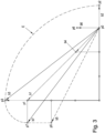
- the envelope E is determined from the starting position p0 and the virtual end positions p1,...p7. However, it can also (see 3 ) braking vectors b1,...,b7, which connect the starting position p0 with the possible (in the simplest case at least one) virtual end positions p1,...,p7, are determined and the envelope E is calculated using the braking vectors b1,... ,b7 can be determined.
- the braking vectors b1,...,b7 which are then also used to determine the envelope E (as described below), can also be formed from a linear combination of basic braking vectors, with each basic braking vector being assigned to a moving individual axis Q1, Q2, Q3 . For each basic braking vector, the assumption is made that the individual axles Q1, Q2, Q3 that are not assigned to the basic braking vector do not move any further.
- the associated virtual end position p1, p2, p4 of point P is calculated from the initial position p0 of point P, a vectorial speed v1, v2, v3 and the minimum deceleration a1, a2, a3 only determined for the assigned individual axis Q1, Q2, Q3.
- the basic braking vector then connects the starting position p0 of point P with this associated virtual end position p1, p2, p4 of point P.
- FIG. 2b shows an example of the virtual end position p1 when the first single axis Q1, which is moving at the first speed v1, is braked with the minimum deceleration a1 (not shown), with an immediate standstill being assumed for the second single axis Q2 and the third single axis Q3, i.e. the movement of the second single axis Q2 and the third single axis Q3 is not taken into account.
- FIG. 2c again shows the virtual end position p2 when the second single axis Q2, which is moving at the second speed v2, is braked with the minimum deceleration a2 (not shown), where it was assumed for the first single axis Q1 and the third single axis Q3 that they come to a standstill immediately or that they are not moved.
- Figure 2e shows the virtual end position p4 when the third single axis Q3, which is moving at the third speed v3, is braked with the minimum deceleration a3 (not shown), it being assumed for the first single axis Q1 and the second single axis Q2 that they come to a standstill immediately or these not be moved.
- Fig.2h discloses, as mentioned, braking of the first single axle Q1, the second single axle Q2 and the third single axle Q3, each with the minimum deceleration a1, a2, a3 (not shown).
- Figures 2d, 2f, 2g, 2h The illustrated virtual end positions p3, p5, p6, p7 of point P can thus also be used as linear combinations of the in Figures 2b, 2c, 2e shown virtual end positions p1, p2, p4 of the point P are shown.
- velocities v1, v2, v3 occur in Fig.2 of course only at the beginning of the braking process, since they are then delayed by the delay a1, a2, a3.
- Fig.2 no velocities v1, v2, v3 are shown, this simply means that it is assumed that the associated individual axis Q1, Q2, Q3 is braked immediately, and not that they do not move until the braking time.
- All possible virtual end positions p1, . . . p7 of point P of kinematics 1 are thus determined during braking.
- the starting positions p1a, p2a, p3a of the individual axes Q1, Q2, Q3 are assumed and the individual axes Q1, Q2, Q3 are each, preferably minimally, delayed, whereby they reach the end positions p1e, p2e, p3e.
- a variation of the end positions p1e, p2e, p3e results in the virtual end positions p1,...p7 of point P.
- the virtual end positions p1,...,p7 consist of vector speeds v1, v2, v3 and decelerations a1, a2 , a3 of the individual axes Q1, Q2, Q3 are determined, not only the position but also the direction of movement of the individual axes Q1, Q2, Q3 is taken into account during the braking process.
- braking vectors b1, . . . , b7 are used to determine the envelope E.
- a calculation of the envelope E would of course also be possible if the starting position p0 and the at least one virtual end position p1,...,p7 are used directly without determining the braking vectors b1,...,b7.
- the braking vectors b1,...,b7 can be determined as linear combinations of the associated basic braking vectors.
- b1 would be a basic braking vector for the first individual axle Q1
- b2 would be a basic braking vector for the second individual axle Q2
- b4 would be a basic braking vector for the third individual axle Q3, cf Fig.2 .
- a braking vector b1,...,b7 is formed by a virtual end position p1,...,p7, which is only created by extending a sliding joint axis (in 3 for example the (basic) braking vector b2)
- the respective braking vector b1,...,b7 (here the braking vector b2) as a straight connection between the starting position p0 and the virtual end position (here p2) corresponds to the actual trajectory of point P during the braking movement, when the second single axis Q2 is decelerated with the second minimum deceleration a2 and the first and third single axes Q1, Q3 are not moved.
- a circular arc naturally results as a virtual partial movement when the individual axis connected to it moves.
- the actual trajectory of point P is unknown.
- the virtual partial movements of the point P are determined on the basis of individual movements of the individual axes Q1, Q2, Q3 joint movements or a combination of movements under the effect of the minimum deceleration a1, a2, a3 at an initial speed v1, v2, v3.
- the braking range of point P is determined by means of an envelope E.
- the envelope E is a one-dimensional (e.g. when only one sliding joint axis moves), two-dimensional or three-dimensional object, which includes the determined braking vectors b1,...,b7 and whose extent is calculated from the braking vectors b1,...,b7.
- the envelope E can include exactly the family of braking vectors b1,...,b7, which minimizes the expansion of the envelope E.
- the envelope E could also be formed as the smallest surrounded object of the group of possible virtual partial movements.
- the virtual part movements are but mostly unknown, but could be calculated from the braking vectors, usually with a lot of computing effort.
- the virtual partial movements can also be determined by intermediate positions of the point P between the respective virtual end positions p1,...,p7, for example by also connecting the virtual end positions p1,...,p7 with vectors and calculating the envelope E therefrom.
- a possible envelope E, which includes the virtual partial movements, is in 3 shown dashed.
- a virtual partial movement of the point P deviates from the respective (basic) braking vectors b1,...,b7, which are formed by pivoting a rotary joint axis.
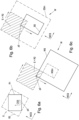
- An exemplary virtual partial movement of the point P ie the kinematic object O3, which describes an arc of a circle due to a rotation of only the first individual axis Q1, is shown in FIG Figures 4a and 4b shown.
- the braking vector b1 (a basic braking vector since only the first single axis Q1 was moved) connects the starting position p0 with the virtual end position p1.
- a vectorial velocity v1 of at least one individual axis Q1, Q2, Q3 and a further deceleration a1', a1", greater than the minimum deceleration a1, a2, a3 of at least one individual axis Q1, Q2 , Q3 at least one virtual end position p1', p1" of the point P can be determined.
- a first further end position p1′, which results from a first further deceleration a1′, and a second further end position p1′′, which results from a second further deceleration a1′′, are taken into account here.
- a first further braking vector b1' which connects the starting position p0 with the first further virtual end position p1', and a second further braking vector b1", which connects the starting position p0 with the second further virtual end position p1", are determined.
- the extension of the envelope E can be calculated or approximated from the first braking vector b1, the first and second further braking vector b1', b1".
- the extension of the envelope E can also be calculated from the starting position p0, the at least one end position p1 and the at least one virtual end position p1', p1" are calculated without calculating the braking vector b1 or the at least one further braking vector b1', b1".
- the envelope E can also advantageously be calculated from the braking vectors b1,...,b7, or starting position p0 and virtual end positions p1,...,p7, by defining the envelope E as a first rectangle R1, which contains the braking vectors b1,...,b7 minimal bounding rectangle whose sides are parallel to the kinematic coordinate system CGS, is calculated as in Figure 5a shown.
- the first rectangle R1 as the envelope E is preferably corrected by a correction value h, which at least compensates for a deviation of the braking vectors b1,...,b7 from the virtual partial movements of the point P from the starting position p0 to the respective virtual end positions p1,..., p7 taken into account, extended to an extended first rectangle R1' as envelope E ( Fig.5b ).
- the braking vector b1 deviates from the virtual partial movement drawn in dashed lines by a circle segment drawn in hatched with the circle segment height h1.
- the above correction value h can thus be determined as the sum of all circle segment heights h1.
- the circle segment heights h1 each describe the deviation from the basic braking vectors b1, . . .
- the circle segment height which describes the deviation of the fourth basic braking vector b4 from the associated virtual partial movement, would therefore also have to be taken into account for the kinematics 1 shown.
- known geometric or trigonometric methods can be used to determine the respective circle segment heights h1, whereby the starting position p0 and virtual end position p1,...,p7, as well as axis lengths, distances to the origin CGSO, etc. can be used.
- the envelope using the further delays a1 ', a1 ", and a first Rectangle R1, which includes a rectangle R1 minimally surrounding the braking vectors b1,...,b7 and/or and a rectangle R1' extended by the correction value h are determined.
- Fig.5b shows an envelope E, which represents a first rectangle R1' expanded by a correction value h (for example as the sum of the circle segment heights h1).
- h for example as the sum of the circle segment heights h1.
- the positions of the kinematic objects O1, O2, O3 are in Fig.5a and Figure 5b only implied.
- Direction-independent braking distance components can also be determined for the individual axes Q1, Q2, Q3, which can cause a movement of the individual axes Q1, Q2, Q3 in all spatial directions.
- Direction-independent braking distance components can arise, for example, as a result of a position tolerance, which describes a position deviation of a determined braking vector b1,...,b7 from the actual position of point P. Since the envelope E encloses all braking vectors b1,...,b7 of the kinematics 1, the envelope E or the first rectangle R1 can again be expanded by taking into account the direction-independent braking distance components, for example by further adapting the correction value h.
- the envelope E can be transformed into a workspace coordinate system WCS, in which a workspace W with a safety area SS of the kinematics 1 and/or a workspace WS of the kinematics 1 is located.
- Workspace W or safety area SS and/or workspace WS can advantageously only belong to one point P, with several associated workrooms W or safety areas SS and/or workspaces WS being available for further points P.
- a braking area could also be composed of a number of points P and subsequently a work space W, or safety area SS and/or work area WS for a number of points P, could be calculated. However, this is far more conservative and can also be more computationally expensive.
- the braking range is determined and WS/SS adjusted. For each point there are different WS/SS.
- the safety area SS of the kinematics 1 can be expanded by means of the envelope E and/or the working area WS of the kinematics 1 can be reduced by means of the envelope E, whereupon a modified safety area SSm or a modified working area WSm is generated.
- the envelope E can on a second Rectangle R2, the sides of which touch the corners of the first rectangle R1 and are parallel to the workspace coordinate system WCS, can be expanded, as in Figure 6a shown.
- the first rectangle R1 could also be expanded to a first expanded rectangle R1' using the correction value h, and the first expanded rectangle R1' used to determine the second rectangle R2.
- the safety zone can be modified by moving the considered initial position p0 of point P along the boundaries of the safety zone SS and the modified safety zone SSm is formed by the sum of the safety zone SS and the envelope E, as in Figure 6b shown.
- the safety range SS is thus expanded by the envelope E that has been shifted based on the point P, with the result that the safety range SS is enlarged to the modified safety range SSm.
- the modified working range WSm can be formed analogously by the difference between working range WS and envelope E, as in Figure 6c shown.
- the working area WS is thereby reduced by the envelope E that has been shifted using the point P, with the result that the working area WS is reduced to the modified working area WSm.
- an envelope E which encloses the start position p0 and virtual end positions p1,...,p7, is calculated. It is also possible to form braking vectors b1,...,b7, which connect the starting position p0 with the respective virtual end positions p1,...,p7, and an envelope E enclosing the braking vectors b1,...,b7 from the braking vectors b1 ,...,b7 can be calculated.
- a first rectangle R1, which includes the braking vectors b1,...,b7, or starting position and virtual end positions p1,...,p7, can be formed and optionally extended by a correction value h.
- the correction value h can take into account the deviation of the braking vectors b1,...,b7 from the virtual partial movements, as well as direction-independent braking distance components, etc.
- the envelope E can be further transformed into a work space coordinate system WCS and used for the adjustment of work areas WS or safety areas SS.
- kinematics usually enable a three-dimensional movement.
- the determination of the braking range of a point P of the kinematics according to the invention can easily be extended to the three-dimensional case.
- cuboids in three-dimensional space can be used to represent the envelope E in the same way.
- the method according to the invention can of course be used for a number of points P of the kinematics 1 .
- at least one point P per individual axis Q1, Q2, Q3 is considered, with braking vectors b1,...,b7, or starting position and virtual end positions p1,...,p7, from which each envelope E are determined and, if necessary, further work areas WS or safety areas SS are modified.
Description
Die gegenständliche Erfindung behandelt ein Verfahren zur Steuerung einer Kinematik, die in einem Kinematikkoordinatensystem mittels gelenkig miteinander verbundener Einzelachsen modelliert wird, wobei zumindest eine der Einzelachsen mit einem Ursprung des Kinematikkoordinatensystems verbunden ist und sich zumindest eine der Einzelachsen relativ zum Ursprung bewegt.The present invention deals with a method for controlling kinematics that is modeled in a kinematics coordinate system by means of individual axes that are connected to one another in an articulated manner, with at least one of the individual axes being connected to an origin of the kinematics coordinate system and at least one of the individual axes moving relative to the origin.
Da Fertigungsprozesse auf dem Gebiet der Robotik auf immer kleinerem Raum realisiert werden sollen, überschneiden sich die Arbeitsbereiche von Robotern (allgemein auch als Kinematik bezeichnet) oft mit denen von anderen Objekten wie ortsfesten Installationen, Robotern, Maschinen oder Menschen. Als Kinematik werden sowohl serielle Kinematiken, als auch parallele Kinematiken, aber auch Mischungen davon, verstanden, wobei eine serielle oder parallele Kinematik in bekannter Weise eine Anzahl von miteinander, über starre Verbindungselemente, seriell oder parallel (z.B. Tripod oder Hexapod) verbundene Gelenke aufweist. Um einen reibungslosen Ablauf garantieren zu können, muss daher sichergestellt werden, dass keine Kollisionen zwischen einem Roboter und anderen Objekten in diesen gemeinsam genutzten Arbeitsräumen auftreten. Ebenso sind im Arbeitsraum von Kinematiken oftmals Arbeitsbereiche und/oder Sicherheitsbereiche definiert, die von der Kinematik, oder Teilen davon, nicht verlassen werden bzw. nicht passiert werden dürfen. Insbesondere ist aufgrund hoher und steigender Sicherheitsanforderungen der Schutz für Menschen und Objekte zu gewährleisten.Since manufacturing processes in the field of robotics are to be implemented in ever smaller spaces, the working areas of robots (also generally referred to as kinematics) often overlap with those of other objects such as stationary installations, robots, machines or people. Kinematics are understood to mean both serial kinematics and parallel kinematics, but also mixtures thereof, with serial or parallel kinematics having a number of joints connected to one another in a known manner via rigid connecting elements, serially or in parallel (e.g. tripod or hexapod). In order to be able to guarantee a smooth process, it must therefore be ensured that there are no collisions between a robot and other objects in these shared workspaces. Likewise, working areas and/or safety areas are often defined in the workspace of kinematics, which the kinematics or parts of it must not leave or be passed through. In particular, the protection of people and objects must be guaranteed due to high and increasing security requirements.
Es existieren bereits verschiedene Modelle von Kollisionsüberwachungen, welche meist einen Kompromiss aus Genauigkeit, Flexibilität und erforderlicher Rechenleistung darstellen. Meist werden sowohl Roboter(teile), als auch Arbeitsraumgrenzen mithilfe geometrischer Körper (Kugeln, Pyramiden, Voxels) approximiert und während der Bewegung des Roboters laufend überprüft, ob es räumliche Überschneidungen zwischen diesen geometrischen Körpern gibt. Somit wird dafür gesorgt, dass ein Roboter einen gewissen Arbeitsbereich (Work Space) nicht verlässt bzw. einen gewissen Sicherheitsbereich (Safe Space) nicht betritt. Dies wird meist durch Berechnung von Schnittpunkten/Schnittlinien/Schnittflächen geometrischer Körper (z.B. zwischen einem approximierten Roboterarm und einem Sicherheitsbereich) erreicht, was jedoch rechenaufwändig ist. Gerade im Bereich Sicherheit sind jedoch ein geringerer Rechenaufwand und damit eine schnelle Reaktionszeit wünschenswert. Je geringer die Reaktionszeit, umso später muss der Roboter auf kritische Situationen reagieren. Neben der Position ist auch ein Bremsweg einer Kinematik während des Betriebs zu berücksichtigen. Wird zu einem Bremszeitpunkt ein Bremsvorgang eingeleitet, so bewegen sich die Gelenke und Arme eines Roboters weiter, bis sie in einer Endposition verharren. Es muss sichergestellt werden, dass bei Einleitung einer Bremsung durch die unvermeidbare Bremsbewegung der Kinematik Arbeitsräume nie verlassen und Sicherheitsbereiche nie betreten werden. Eine bekannte Herangehensweise zur Berücksichtigung des Bremswegs ist es einen Kreis bzw. eine Kugel als möglichen Bremsweg anzunehmen, wobei der Radius des Kreises bzw. der Kugel sich aus der Summe der möglichen Einzelbremswege von Einzelachsen zusammensetzt. Diese Methode ist zwar hinsichtlich der Rechenzeit sehr effizient, jedoch auch sehr konservativ, da der Bereich, der bei einem Bremsvorgang tatsächlich überstrichen wird bzw. werden kann, in der Regel nur einen Bruchteil des ermittelten Bremswegs darstellt. Durch diese großzügige Auslegung des Bremsbereichs kann es somit vorkommen, dass eine Bremsung eingeleitet wird, obwohl gar keine Kollisionsgefahr besteht.Various models of collision monitoring already exist, which usually represent a compromise between accuracy, flexibility and the required computing power. In most cases, both robot (parts) and workspace boundaries are approximated using geometric bodies (spheres, pyramids, voxels) and continuously checked during the movement of the robot to determine whether there are spatial overlaps between these geometric bodies. This ensures that a robot does not leave a certain working area (work space) or does not enter a certain safety area (safe space). This is usually achieved by calculating intersection points/intersection lines/intersection surfaces of geometric bodies (e.g. between an approximated robot arm and a safety area), which is computationally expensive. Especially in the field of security, however, less computing effort and thus a fast response time are desirable. The lower the reaction time, the later the robot has to react to critical situations. In addition to the position, a braking distance of a kinematics during operation must also be taken into account. If a braking process is initiated at a braking point, the joints and arms of a robot continue to move until they remain in an end position. It must be ensured that when braking is initiated Due to the unavoidable braking movement of the kinematics, work areas are never left and safety areas are never entered. A known approach for considering the braking distance is to assume a circle or a sphere as the possible braking distance, with the radius of the circle or the sphere being composed of the sum of the possible individual braking distances of individual axles. Although this method is very efficient in terms of computing time, it is also very conservative, since the area that is or can actually be swept over during a braking process usually represents only a fraction of the braking distance determined. Due to this generous design of the braking area, it can happen that braking is initiated even though there is no risk of a collision.
In
Es ist somit die Aufgabe der vorliegenden Erfindung ein Verfahren zur Steuerung einer Kinematik anzugeben, wobei ein bei einem Bremsvorgang von der Kinematik möglicherweise überstrichener Bremsbereich mit erhöhter Genauigkeit und Effizienz berechnet wird.It is therefore the object of the present invention to specify a method for controlling a kinematic system, wherein a braking range that may be covered by the kinematic system during a braking process is calculated with increased accuracy and efficiency.
Diese Aufgabe wird erfindungsgemäß durch das in Anspruch 1 definierte Verfahren gelöst. Im Rahmen der Erfindung wird dabei unter anderem bei einem Bremsvorgang für einen mit einer Einzelachse gekoppelten Punkt aus einer Anfangsposition des Punktes, einer vektoriellen Geschwindigkeit zumindest einer Einzelachse und einer minimalen Verzögerung zumindest einer Einzelachse zumindest eine virtuelle Endposition des Punktes ermittelt wobei die Ausdehnung einer Einhüllenden aus der Anfangsposition und der zumindest einen virtuellen Endposition berechnet wird. Ein Bremsbereich des Punktes wird durch die Einhüllende der Anfangsposition und der zumindest einen Endposition bestimmt und der Bremsbereich bei der Steuerung der Kinematik berücksichtigt. "Vektorielle Geschwindigkeit" bedeutet, dass neben dem Betrag der Geschwindigkeit auch die Richtung der Geschwindigkeit berücksichtigt wird, wobei die vektorielle Geschwindigkeit der Anfangsgeschwindigkeit bei Einleiten des Bremsvorgangs entspricht. Eine vektorielle Geschwindigkeit einer bewegten Drehgelenksachse kann als Winkelgeschwindigkeit entlang einer zugehörigen Drehachse beschreiben werden und eine vektorielle Geschwindigkeit einer Schubgelenksachse als Geschwindigkeit entlang einer zugehörigen Schubachse.This object is achieved according to the invention by the method defined in claim 1. Within the scope of the invention, at least one virtual end position of the point is determined, among other things, during a braking process for a point coupled to a single axis from an initial position of the point, a vectorial speed of at least one single axis and a minimal deceleration of at least one single axis, with the extension of an envelope from the starting position and the at least one virtual end position is calculated. A braking range of the point is determined by the envelope of the starting position and the at least one end position, and the braking range is taken into account when controlling the kinematics. "Vectoral speed" means that in addition to the amount of speed, the direction of the speed is also taken into account, with the vectorial speed corresponding to the initial speed when the braking process is initiated. A vectorial velocity of a moving pivot axis can be described as an angular velocity along an associated rotational axis and a vectorial velocity of a sliding joint axis as a velocity along an associated thrust axis.
Während des Bremsvorgangs verringert sich die jeweilige Geschwindigkeit natürlich aufgrund der auftretenden Verzögerung weiterhin. Die ermittelte virtuelle Endposition entspricht in der Regel natürlich nicht der tatsächlichen Endposition des Punkts nach dem Bremsvorgang, wobei der Punkt die virtuelle Endposition jedoch schon erreichen könnte - wenn einerseits die betreffende Einzelachse tatsächlich mit der minimalen Verzögerung verzögert wird und andererseits keine weitere Einzelachse in Bewegung, bzw. am Bremsvorgang beteiligt ist. Die minimale Verzögerung kann gegeben sein oder berechnet werden und beschreibt die Verzögerung, mit welcher die zumindest eine Einzelachse während des Bremsvorgangs garantiert verzögert werden kann. Es wird also sichergestellt, dass der Punkt garantiert innerhalb des ermittelten Bremsbereichs zum Stillstand kommt. Die minimale Verzögerung kann aus den dynamischen Eigenschaften von Teilen der Kinematik, beispielsweise der Masse einer Einzelachse, sowohl während des Betriebs der Kinematik als auch vorab ermittelt werden. Natürlich kann die minimale Verzögerung auch vorab oder während des Betriebs, z.B. als externer Parameter vorgegeben werden, etc.During the braking process, the respective speed naturally continues to decrease due to the deceleration that occurs. Of course, the determined virtual end position usually does not correspond to the actual end position of the point after the braking process, although the point could already reach the virtual end position - if on the one hand the individual axis in question is actually decelerated with the minimum deceleration and on the other hand no other individual axis is moving, or is involved in the braking process. The minimum deceleration can be given or can be calculated and describes the deceleration with which the at least one individual axis can be guaranteed to be decelerated during the braking process. It is therefore ensured that the point is guaranteed to come to a standstill within the determined braking zone. The minimum deceleration can be determined from the dynamic properties of parts of the kinematics, for example the mass of a single axis, both during the operation of the kinematics and in advance. Of course, the minimum delay can also be specified in advance or during operation, e.g. as an external parameter, etc.
Die Verzögerung der zumindest einen Einzelachse wirkt gegen die Geschwindigkeit der zumindest einen Einzelachse und stellt somit eine negative, gegen die Geschwindigkeit gerichtete Beschleunigung dar. Die minimale Verzögerung der betrachteten Einzelachse ergibt sich zum Bremszeitpunkt aus einem verfügbaren Bremsmoment, der Beladung, etc., kann auch mit der aktuellen Geschwindigkeit, usw. in Beziehung stehen, oder auch vorab bekannt sein. Eine vorgegebene minimale Verzögerung für eine bestimmte Beladung der Kinematik kann beispielsweise aus einem Datenblatt entnommen werden. Es kann für die für das Verfahren verwendete minimale Verzögerung ein geringerer Wert als für die vorgegebene minimale Verzögerung angenommen werden um einen zusätzlichen Sicherheitsfaktor zu realisieren. Damit kann der Fall, dass z.B. ein Motor der Kinematik aufgrund einer Fehlfunktion nicht so stark bremsen kann, wie vorgegeben oder die Beladung der Kinematik schwerer ist als vorgegeben, etc. berücksichtigt werden.The deceleration of the at least one individual axle acts against the speed of the at least one individual axle and thus represents a negative acceleration directed against the speed. The minimum deceleration of the individual axle under consideration results at the braking time from an available braking torque, the load, etc related to current speed, etc., or known in advance. A specified minimum deceleration for a specific loading of the kinematics can be taken from a data sheet, for example. A lower value can be assumed for the minimum delay used for the method than for the specified minimum delay in order to implement an additional safety factor. This means that, for example, a motor in the kinematics cannot brake as hard as specified due to a malfunction or the loading of the kinematics is heavier than specified, etc. can be taken into account.
Es wird im Gegensatz zum Verfahren nach dem Stand der Technik kein Kinematikobjekt als dreidimensionaler geometrischer Körper modelliert. Stattdessen kann für die Ermittlung des Bremswegs zumindest eine Endposition eines Punkts der Kinematik als zu überwachendes Objekt betrachtet werden, wobei die Kinematik durch eine Anzahl an Einzelachsen (linienförmige, d.h. eindimensionale Objekte), die beispielsweise jeweils zwei Kinematikobjekte, z.B. Gelenknaben (punktförmige, d.h. nulldimensionale Objekte) verbinden, modelliert werden. Der betrachtete Punkt kann sich dabei auf einer modellierten Einzelachse oder einem Kinematikobjekt der Kinematik befinden, muss aber zumindest mit einer Einzelachse gekoppelt sein, z.B. sich mit einer Einzelachse bewegen. Dazu kann sich der Punkt jedoch außerhalb der (durch Einzelachsen und Kinematikobjekte modellierten) Kinematik befinden. Der Bremsvorgang wird zu einem Bremszeitpunkt, zu dem sich der Punkt in der Anfangsposition befindet, eingeleitet. Es wird zumindest eine virtuelle Endposition des Punktes aus der vektoriellen Geschwindigkeit und der gegebenen minimalen Verzögerung zumindest einer Einzelachse ermittelt und zumindest ein Bremsvektor kann aus der Anfangsposition und der zumindest einen virtuellen Endposition ermittelt werden.In contrast to the method according to the prior art, no kinematic object is modeled as a three-dimensional geometric body. Instead, at least one end position of a point of the kinematics can be considered as an object to be monitored for determining the braking distance, with the kinematics being defined by a number of individual axes (linear, i.e. one-dimensional objects), which, for example, each have two kinematic objects, e.g. joint hubs (point-shaped, i.e. zero-dimensional connect objects) to be modeled. The point under consideration can be on a modeled single axis or a kinematics object of the kinematics, but must at least be coupled to a single axis, e.g. move with a single axis. However, the point can be outside of the kinematics (modeled by individual axes and kinematic objects). Braking is initiated at a braking time point when the point is in the initial position. At least one virtual end position of the point is determined from the vectorial speed and the given minimum deceleration of at least one individual axis, and at least one braking vector can be determined from the start position and the at least one virtual end position.
Die Einhüllende ist ein zweidimensionales oder dreidimensionales Objekt, welches den zumindest einen ermittelten Bremsvektor umfasst. In einfacher Weise kann die Einhüllende den zumindest einen Bremsvektor exakt umhüllen, was jedoch nur sinnvoll ist, wenn der zumindest eine Bremsvektor nicht von der virtuellen Teilbewegung des Punkts während des Bremsvorgangs abweicht, bzw. abweichen kann. Dieser Fall tritt beispielsweise ein, wenn nur ein Bremsvektor vorhanden ist, der zudem durch die Bewegung nur einer Schubgelenksachse gebildet wird.The envelope is a two-dimensional or three-dimensional object that includes the at least one determined braking vector. In a simple manner, the envelope can envelop the at least one braking vector exactly, but this only makes sense if the at least one braking vector is not affected by the virtual partial movement of the point during the Braking process deviates, or can deviate. This case occurs, for example, when there is only one braking vector, which is also formed by the movement of only one sliding joint axis.
Vorteilhafterweise kann die Ausdehnung der Einhüllenden E aus der Anfangsposition, der zumindest einen virtuellen Endposition und einer sich daraus ergebenden virtuellen Teilbewegung berechnet werden.Advantageously, the extent of the envelope E can be calculated from the starting position, the at least one virtual end position and a resulting virtual partial movement.
Als virtuelle Teilbewegung wird eine mögliche Trajektorie verstanden, die im Rahmen des erfindungsgemäßen Verfahrens unter Verwendung der minimalen Verzögerung aus der virtuellen Endposition ermittelt wird. Die tatsächliche Trajektorie als tatsächlicher Bewegungspfad des Punktes während des Bremsvorgangs ist natürlich unbekannt, u.a. da üblicherweise die tatsächlich auftretende Verzögerung nicht bekannt ist.A possible trajectory is understood as a virtual partial movement, which is determined within the scope of the method according to the invention using the minimum delay from the virtual end position. The actual trajectory as the actual movement path of the point during the braking process is of course unknown, among other things because the deceleration that actually occurs is usually not known.
Da jedoch meist mehrere Einzelachsen an der Bewegung und am Bremsvorgang beteiligt sind, kann die virtuelle Teilbewegung des Punktes üblicherweise nicht als gerade Verbindung von Anfangspunkt und Endpunkt angesehen werden. Die tatsächliche Trajektorie ist wie auch die tatsächliche Endposition nicht bekannt. Die Einhüllende kann aber derart gewählt werden, dass alle Trajektorien, die während des Bremsvorgangs auftreten könnten, von der Einhüllenden umhüllt werden, falls die minimale Verzögerung eingehalten wird, was vorausgesetzt wird. Die virtuellen Teilbewegungen können dann ausgehend vom Anfangspunkt und zumindest einen Endpunkt berechnet werden, und die Einhüllende derart gestaltet werden, dass sie alle virtuellen Teilbewegungen möglichst genau umfasst. Damit können sich komplexe Geometrien für die Einhüllende ergeben, was meist einen hohen Rechenaufwand zur Folge hat, welcher jedoch mit geeigneten Algorithmen gering gehalten werden kann.However, since several individual axes are usually involved in the movement and the braking process, the virtual partial movement of the point cannot usually be viewed as a straight connection between the starting point and the end point. The actual trajectory, like the actual end position, is not known. However, the envelope can be selected in such a way that all trajectories that could occur during the braking process are enveloped by the envelope if the minimum deceleration is observed, which is assumed. The virtual partial movements can then be calculated starting from the starting point and at least one end point, and the envelope can be designed in such a way that it encompasses all virtual partial movements as precisely as possible. This can result in complex geometries for the envelope, which usually results in a high computational effort, which can, however, be kept low with suitable algorithms.
Um den Rechenaufwand zu verringern, können als Einhüllende auch einfache geometrische Formen, wie Rechtecke (im zweidimensionalen Raum) oder Quader (im dreidimensionalen Raum), die aus dem Anfangspunkt und zumindest einen Endpunkt berechnet werden (und natürlich immer Anfangspunkt und zugehörigen zumindest einen Endpunkt, bzw. die virtuellen Teilbewegungen umfassen müssen), ermittelt werden, wie weiter unten beschrieben wird.In order to reduce the computing effort, simple geometric shapes such as rectangles (in two-dimensional space) or cuboids (in three-dimensional space) can also be used as envelopes, which are calculated from the starting point and at least one end point (and of course always the starting point and associated at least one end point, or which must include virtual partial movements), as will be described further below.
Es wird vorteilhafterweise die zumindest eine virtuelle Endposition des Punktes aus der Anfangsposition des Punktes, einer vektoriellen Geschwindigkeit jeder bewegten Einzelachse und einer minimalen Verzögerung jeder bewegten Einzelachse ermittelt. Damit wird die Bewegung, d.h. die vektorielle Geschwindigkeit und die minimale Verzögerung, jeder Einzelachse bei der Ermittlung der virtuellen Endposition direkt berücksichtigt. Die vektorielle Geschwindigkeit des Punktes ergibt sich somit als Linearkombination von vektoriellen Geschwindigkeiten der bewegten Einzelachsen.The at least one virtual end position of the point is advantageously determined from the starting position of the point, a vectorial speed of each moving individual axis and a minimum deceleration of each moving individual axis. This means that the movement, ie the vectorial speed and the minimum deceleration, of each individual axis is directly taken into account when determining the virtual end position. The vectorial speed of the point is thus obtained as a linear combination of vectorial speeds of the moving individual axes.
Es wird allgemein zumindest eine virtuelle Endposition des Punktes aus der vektoriellen Geschwindigkeit und der gegebenen minimalen Verzögerung zumindest einer (oder auch jeder) Einzelachse ermittelt. Es kann jedoch auch zumindest ein Bremsvektor, welcher die Anfangsposition mit der zumindest einen virtuellen Endposition verbindet, ermittelt werden und die Ausdehnung einer Einhüllenden aus dem zumindest einen Bremsvektor berechnet werden.In general, at least one virtual end position of the point is determined from the vectorial speed and the given minimum deceleration of at least one (or also each) individual axis. However, at least one braking vector, which connects the starting position with the at least one virtual end position, can also be determined and the extension of an envelope can be calculated from the at least one braking vector.
In einfacher Weise kann die Einhüllende den zumindest einen Bremsvektor exakt umhüllen, was jedoch nur sinnvoll ist, wenn der zumindest eine Bremsvektor nicht von der virtuellen Teilbewegung des Punkts während des Bremsvorgangs abweicht, bzw. abweichen kann. Dieser Fall tritt beispielsweise ein, wenn nur ein Bremsvektor vorhanden ist, der zudem durch die Bewegung nur einer Schubgelenksachse gebildet wird.In a simple manner, the envelope can envelop the at least one braking vector exactly, but this only makes sense if the at least one braking vector does not deviate or cannot deviate from the virtual partial movement of the point during the braking process. This case occurs, for example, when there is only one braking vector, which is also formed by the movement of only one sliding joint axis.
Die Bremsvektoren können vorteilhafterweise aus einer Linearkombination von Basisbremsvektoren gebildet werden, wobei jeder Basisbremsvektor einer Einzelachse zugeordnet wird und die Anfangsposition des Punktes mit einer zugehörigen virtuellen Endposition des Punktes verbindet, wobei die zugehörige virtuelle Endposition des Punktes aus der Anfangsposition des Punktes, einer vektoriellen Geschwindigkeit der zugeordneten Einzelachse und der minimalen Verzögerung der zugeordneten Einzelachse ermittelt wird, wobei für jeden Basisbremsvektor jeweils die Annahme getroffen wird, dass die nicht zugeordneten Einzelachsen sich nicht weiterbewegen. Um den Bremsbereich zu ermitteln, wird die mögliche Trajektorie des Punkts in einzelne virtuelle Teilbewegungen zerlegt. Die Endposition eines einer solchen virtuellen Teilbewegung folgenden Punkts, entspricht der virtuellen Endposition. Die virtuellen Teilbewegungen decken gewissermaßen den "worst case" Fall ab, da sie auf Basis der minimalen Verzögerung ermittelt werden. Der Bremsbereich wird durch Kombination der einzelnen virtuellen Teilbewegungen ermittelt und entspricht dem Bereich, in welchem sich die reale Trajektorie mit Sicherheit befinden wird - natürlich immer unter der Voraussetzung, dass zumindest die minimale Verzögerung wirkt. Die Ausdehnung der Einhüllenden wird erfindungsgemäß aus den Bremsvektoren angenähert, wobei die Einhüllende idealerweise alle virtuellen Teilbewegungen des Punkts derart umfasst, dass die Einhüllende eine möglichst geringe Ausdehnung aufweist.The braking vectors can advantageously be formed from a linear combination of basic braking vectors, with each basic braking vector being assigned to a single axis and connecting the initial position of the point with an associated virtual final position of the point, the associated virtual final position of the point being derived from the initial position of the point, a vectorial speed of the assigned individual axle and the minimum deceleration of the assigned individual axle is determined, with the assumption being made for each basic braking vector that the unassigned individual axles do not move on. In order to determine the braking area, the possible trajectory of the point is broken down into individual virtual partial movements. The end position of a point following such a virtual partial movement corresponds to the virtual end position. To a certain extent, the virtual partial movements cover the "worst case" case, since they are determined on the basis of the minimum delay. The braking area is determined by combining the individual virtual partial movements and corresponds to the area in which the real trajectory will definitely be - of course always assuming that at least the minimum deceleration is effective. According to the invention, the extent of the envelope is approximated from the braking vectors, with the envelope ideally encompassing all virtual partial movements of the point in such a way that the envelope has the smallest possible extent.
Es kann zumindest ein Teil der Einzelachsen als Schubgelenkachsen ausgestaltet sein. Eine virtuelle Teilbewegung eines Punktes beschreibt bei Ausfahren (nur) einer Schubgelenksachse eine Gerade, wenn der betrachtete Punkt mit der jeweiligen Schubgelenksachse gekoppelt ist oder mit einer Einzelachse gekoppelt ist, die mit der Schubgelenksachse verbunden ist. Die vektorielle Geschwindigkeit einer Schubgelenksachse wirkt also entlang dieser Geraden. Diese virtuelle Teilbewegungen entsprechen somit den (Basis)Bremsvektoren, wenn die Einzelachse mit der minimalen Verzögerung verzögert wird, womit die Ermittlung der virtuellen Teilbewegungen aus den Bremsvektoren trivial wäre. Die tatsächliche beim Bremsvorgang beschriebene Trajektorie des Punkts könnte auch kürzer sein, wenn die Einzelachse mit einer größeren, als mit der minimalen Verzögerung gebremst wird.At least some of the individual axles can be designed as sliding joint axles. A virtual partial movement of a point describes a straight line when (only) one sliding joint axis is extended if the point under consideration is coupled to the respective sliding joint axis or is coupled to a single axis that is connected to the sliding joint axis. The vectorial velocity of a sliding joint axis acts along this straight line. These virtual partial movements thus correspond to the (basic) braking vectors when the single axis with the minimum Deceleration is delayed, which would make it trivial to determine the virtual partial movements from the braking vectors. The actual trajectory of the point described during the braking process could also be shorter if the single axle is braked with more than the minimum deceleration.
Bei der Berücksichtigung mehrerer bewegter Schubgelenksachsen kann die Ermittlung einer möglichst gering ausgedehnten Einhüllenden dennoch einen erhöhten Aufwand verursachen. Es kann jedoch zumindest ein Teil der Einzelachsen als Drehgelenkachsen ausgestaltet sein, womit die Betrachtung von Bremsvektoren alleine nicht ausreichend ist, da die reale Bewegung des Punktes aufgrund nur dieses einen Drehgelenks einen Kreisbogen darstellt. Die vektorielle Geschwindigkeit einer Drehgelenksachse wirkt entlang dieses Kreisbogens. Bremsvektor und Kreisbogen unterscheiden sich demzufolge um ein Kreissegmentstück. Eine rechnerische exakte Berücksichtigung dieser Abweichung wäre grundlegend sehr aufwändig.When considering several moving sliding joint axes, the determination of an envelope that is as small as possible can still cause increased effort. However, at least some of the individual axes can be designed as pivot axes, which means that the consideration of braking vectors alone is not sufficient, since the real movement of the point represents an arc of a circle due to just this one pivot joint. The vectorial velocity of a rotary joint axis acts along this circular arc. The braking vector and circular arc consequently differ by one segment of a circle. A mathematically exact consideration of this deviation would fundamentally be very complex.
Vorteilhafterweise wird für den Punkt aus der Anfangsposition, der vektoriellen Geschwindigkeit der zumindest einen Einzelachse und zumindest einer weiteren Verzögerung der zumindest einen Einzelachse, die größer als die minimale Verzögerung der zumindest einen Einzelachse ist, zumindest eine weitere virtuelle Endposition des Punktes Der Bremsbereich des Punkts wird durch eine Einhüllende der Anfangsposition und der zumindest einen Endposition und der zumindest einen weiteren Endposition bestimmt, wobei die Ausdehnung der Einhüllenden aus der Anfangsposition, der zumindest einen Endposition und der zumindest einen weiteren Endposition berechnet wird. Damit kann die virtuelle Teilbewegung des Punkts über weitere Endpositionen, die sich aus einer größeren, als der minimalen Verzögerung ergeben, angenähert werden. Würden unendlich viele weitere Endpositionen ermittelt werden, so würde sich aus der Schar der Anfangsposition und Endpositionen die virtuelle Teilbewegung für alle Verzögerungen bis hin zur minimalen Verzögerung ergeben.Advantageously, for the point from the starting position, the vectorial speed of the at least one individual axis and at least one additional deceleration of the at least one individual axis that is greater than the minimum deceleration of the at least one individual axis, at least one additional virtual end position of the point The braking range of the point becomes determined by an envelope of the initial position and the at least one end position and the at least one further end position, the extent of the envelope being calculated from the initial position, the at least one end position and the at least one further end position. In this way, the virtual partial movement of the point can be approximated via further end positions that result from a delay that is greater than the minimum. If an infinite number of further end positions were to be determined, the virtual partial movement for all decelerations down to the minimum deceleration would result from the group of start positions and end positions.
Es kann die Einhüllende auch einen erweiterten Bereich, welcher einfacher berechenbar ist, abdecken.The envelope can also cover an extended area, which is easier to calculate.
In der gegenständlichen Beschreibung werden zur besseren Anschaulichkeit Bremsvektoren berechnet, es könnte jedoch auch jeweils immer die Anfangsposition und die zumindest eine virtuelle Endposition anstatt eines Bremsvektors verwendet werden. Damit kann die Einhüllende also aus der virtuellen Teilbewegung ermittelt werden und diese vorteilhafterweise exakt umfassen.In the present description, braking vectors are calculated for better clarity, but the starting position and the at least one virtual end position could always be used instead of a braking vector. The envelope can thus be determined from the virtual partial movement and advantageously include it exactly.
Die Einhüllende kann somit vorteilhafterweise auf ein erstes Rechteck, das einem die Bremsvektoren, bzw. Anfangsposition und virtuelle Endpositionen, minimal umgebendes Rechteck, dessen Seiten vorzugsweise parallel zum Kinematikkoordinatensystem sind, entspricht, berechnet werden. Die Einhüllende kann analog auch auf einen ersten Quader, der einen die Bremsvektoren, bzw. Anfangsposition und virtuelle Endpositionen, minimal umgebenden Quader, dessen Seiten parallel zum Kinematikkoordinatensystem sind, darstellt, berechnet werden, was für eine Betrachtung der Kinematik im dreidimensionalen Raum vorteilhaft sein kann.The envelope can thus advantageously be based on a first rectangle, which minimally surrounds the braking vectors or initial position and virtual end positions, the sides of which are preferably parallel to the kinematic coordinate system. corresponds to be calculated. The envelope can also be calculated analogously on a first cuboid, which represents a cuboid minimally surrounding the braking vectors, or starting position and virtual end positions, whose sides are parallel to the kinematic coordinate system, which can be advantageous for considering the kinematics in three-dimensional space .
Damit umfasst der minimal umgebende Quader bzw. das minimal umgebende Rechteck jedoch nur die Bremsvektoren, bzw. Anfangsposition und virtuelle Endpositionen, die wie erwähnt bei Verwendung von Drehgelenksachsen von den virtuelle Teilbewegungen abweichen können.However, the minimally surrounding cuboid or minimally surrounding rectangle only includes the braking vectors, or starting position and virtual end positions, which, as mentioned, can deviate from the virtual partial movements when using rotary joint axes.
Das erste Rechteck, bzw. der erste Quader, kann somit um einen, vorzugsweise richtungsunabhängigen, Korrekturwert, der zumindest die Abweichung der Bremsvektoren von den virtuellen Teilbewegungen des Punktes von der Anfangsposition in die jeweiligen virtuellen Endpositionen berücksichtigt, auf ein erweitertes erstes Rechteck, bzw. einen ersten erweiterten ersten Quader, erweitert werden. Die Einhüllende wird weiters ebenso auf das erweiterte erste Rechteck, bzw. den ersten erweiterten ersten Quader, erweitert. Durch die Verwendung des Korrekturwerts können Drehgelenksachsen berücksichtigt werden, indem erst die zugehörigen Bremsvektoren (die bekanntermaßen um einen Kreissektor von den virtuelle Teilbewegungen abweichen) zur Bildung des ersten Rechtecks herangezogen werden. In weiterer Folge können vorteilhafterweise die Abweichungen der virtuelle Teilbewegungen von den Bremsvektoren in Form der Höhe der jeweiligen Kreissektoren zur Länge und Breite des Rechtecks hinzugefügt werden um dieses auf ein erweitertes erstes Rechteck zu erweitern. Der Korrekturwert kann auch richtungsunabhängige Bremsweganteile, vorzugsweise Positionstoleranzen der Einzelachsen berücksichtigen. Der Korrekturwert kann auch richtungsunabhängige Bremsweganteile, welche aus zu erwartende Abweichungen zwischen berechneten und realen Position resultieren, berücksichtigen. Diese erwartete Abweichung kann sich wiederum durch bekannte Fehlerreaktionszeiten, Differenzenquotienten, Diskretisierungsfehler, Extrapolationsungenauigkeiten, Rechenungenauigkeiten, Geber- und/oder Kopplungsauflösungen, Offsetfehler, mechanische Verformungen, etc. ergebenThe first rectangle or the first cuboid can thus be corrected by a correction value, preferably direction-independent, which at least takes into account the deviation of the braking vectors from the virtual partial movements of the point from the starting position to the respective virtual end positions, to an extended first rectangle or a first expanded first cuboid. The envelope is also extended to the extended first rectangle or the first extended first cuboid. By using the correction value, rotary joint axes can be taken into account by first using the associated braking vectors (which, as is known, deviate from the virtual partial movements by a sector of a circle) to form the first rectangle. Subsequently, the deviations of the virtual partial movements from the braking vectors in the form of the height of the respective circle sectors can advantageously be added to the length and width of the rectangle in order to expand this to an extended first rectangle. The correction value can also take into account non-directional braking distance components, preferably position tolerances of the individual axles. The correction value can also take into account non-directional braking distance components that result from expected deviations between the calculated and the real position. This expected deviation can in turn result from known error reaction times, difference quotients, discretization errors, extrapolation inaccuracies, calculation inaccuracies, encoder and/or coupling resolutions, offset errors, mechanical deformations, etc
Weiters kann in einem Arbeitsraum mit einem Arbeitsraumkoordinatensystem ein Sicherheitsbereich der Kinematik mittels der Einhüllenden erweitert und/oder ein Arbeitsbereich der Kinematik mittels der Einhüllenden verringert werden, woraufhin ein modifizierter Sicherheitsbereich bzw. ein modifizierter Arbeitsbereich erzeugt wird.Furthermore, in a workspace with a workspace coordinate system, a safety area of the kinematics can be expanded using the envelope and/or a working area of the kinematics can be reduced using the envelope, whereupon a modified safety area or a modified working area is generated.
Es kann jedoch auch das erste Rechteck, bzw. der erste Quader um einen Korrekturwert, der zumindest die Abweichung der Bremsvektoren von den virtuellen Teilbewegungen des Punkt von der Anfangsposition in die jeweiligen virtuellen Endpositionen berücksichtigt, auf ein erweitertes erstes Rechteck, bzw. einen ersten erweiterten Quader, erweitert werden, wobei in einem Arbeitsraum mit einem Arbeitsraumkoordinatensystem ein Sicherheitsbereich der Kinematik und/oder ein Arbeitsbereich der Kinematik vorhanden ist, die Einhüllende auf ein zweites erweitertes Rechteck, bzw. einen zweiten erweiterten Quader, dessen Seiten die Ecken des ersten erweiterten Rechtecks, bzw. des ersten erweiterten Quaders, berühren und parallel zum Arbeitsraumkoordinatensystem liegen, erweitert werden und ein Sicherheitsbereich der Kinematik mittels der Einhüllenden erweitert und/oder ein Arbeitsbereich der Kinematik mittels der Einhüllenden verringert werden, woraufhin ein modifizierter Sicherheitsbereich bzw. ein modifizierter Arbeitsbereich erzeugt wird. Die Anpassung des Arbeitsbereichs auf den verringerten Arbeitsbereich bzw. des Sicherheitsbereichs auf den erweiterten Schutzbereich unter Verwendung der Einhüllenden kann auf geeignete Weise erfolgen.However, the first rectangle or the first cuboid can also have a correction value that takes into account at least the deviation of the braking vectors from the virtual partial movements of the point from the starting position to the respective virtual end positions an expanded first rectangle or a first expanded cuboid, with a safety area of the kinematics and/or a working area of the kinematics being present in a workspace with a workspace coordinate system, the envelope to a second expanded rectangle or a second expanded cuboid , whose sides touch the corners of the first extended rectangle or the first extended cuboid and lie parallel to the workspace coordinate system, are extended and a safety area of the kinematics is extended by means of the envelope and/or a working area of the kinematics is reduced by means of the envelope, whereupon a modified safety area or a modified working area is generated. The working area can be adapted to the reduced working area or the safety area to the extended protection area using the envelope in a suitable manner.
Die Anfangsposition des Punkts kann vorteilhafterweise entlang der Grenzen des Sicherheitsbereichs bzw. des Arbeitsbereichs bewegt werden und der modifizierte Sicherheitsbereich durch die Summenmenge aus Sicherheitsbereich und Einhüllender gebildet werden bzw. der modifizierte Arbeitsbereich durch die Differenz von Arbeitsbereich und Einhüllender gebildet werden. Es wird also die Einhüllende auf den zu überwachenden Arbeitsraum (erlaubter Arbeitsbereich oder verbotener Sicherheitsbereich) angewendet. Dabei wird der Arbeitsraum vergrößert (im Falle des Sicherheitsbereichs) oder verkleinert (im Falle des Arbeitsbereichs). Dabei müssen keine Schnittpunkte zweier dreidimensionaler geometrischer Körper berechnet werden, sondern lediglich der Schnittpunkt eines Punkts (Kinematikobjekt) oder einer Linie (Einzelachse) mit einem null- ein-, zwei, oder dreidimensionalen Arbeitsbereich. Es wird also nicht die Kinematik selbst modifiziert, weshalb ein Kinematikobjekt nicht als zweidimensionales oder dreidimensionales Objekt behandelt werden muss.The starting position of the point can advantageously be moved along the boundaries of the safety area or the working area and the modified safety area can be formed by the sum of the safety area and the envelope or the modified working area can be formed by the difference between the working area and the envelope. The envelope is therefore applied to the workspace to be monitored (permitted workspace or prohibited safety area). The working space is enlarged (in the case of the safety area) or reduced (in the case of the working area). There is no need to calculate the intersections of two three-dimensional geometric bodies, just the intersection of a point (kinematic object) or a line (single axis) with a zero, one, two, or three-dimensional working area. The kinematics themselves are therefore not modified, which is why a kinematics object does not have to be treated as a two-dimensional or three-dimensional object.
Der modifizierte Sicherheitsbereich bzw. der modifizierte Arbeitsbereich kann zudem überwacht werden und eine Aktion ausgeführt werden, sobald der Punkt den modifizierten Sicherheitsbereich betritt bzw. der Punkt den modifizierten Arbeitsbereich verlässt. Als Aktion kann eine Abschaltung der Kinematik, Ausgabe eines Warnsignals, etc. dienen.The modified safety area or the modified work area can also be monitored and an action can be carried out as soon as the point enters the modified safety area or the point leaves the modified work area. A shutdown of the kinematics, the output of a warning signal, etc. can serve as an action.
Das erfindungsgemäße Verfahren kann natürlich für mehrere Punkte der Kinematik angewendet werden, vorteilhafterweise für zumindest einen Punkt pro Einzelachse. So können für jeden Punkt jeweils Bremsvektoren und daraus Einhüllende ermittelt werden. Damit können für jeden Punkt zugehörige Arbeitsbereiche bzw. Sicherheitsbereiche modifiziert werden.The method according to the invention can of course be used for a number of points in the kinematics, advantageously for at least one point per individual axis. In this way, braking vectors and the envelopes can be determined for each point. In this way, associated work areas or safety areas can be modified for each point.
Die gegenständliche Erfindung wird nachfolgend unter Bezugnahme auf die
-
Fig.1 eine aus drei Einzelachsen gebildete Kinematik, -
Fig.2a-h die Einzelachsen in der Anfangsstellung und in den Endstellungen, -
Fig.3 Bremsvektoren eines Punkts, -
Fig.4a, b eine virtuelle Teilbewegung des Punktes in Form eines Kreisbogens, -
Fig.5a eine auf ein erstes Rechteck erweiterte Einhüllende, -
Fig.5b eine mittels eines Korrekturwerts erweiterte Einhüllende, -
Fig.6a eine in einen Arbeitsraum transformierte Einhüllende, -
Fig.6b einen modifizierten Sicherheitsbereich, -
Fig.6c einen modifizierten Arbeitsbereich.
-
Fig.1 kinematics made up of three individual axes, -
Fig.2a-h the individual axes in the initial position and in the final positions, -
Fig.3 deceleration vectors of a point, -
Fig. 4a, b a virtual partial movement of the point in the form of a circular arc, -
Fig.5a an envelope extended to a first rectangle, -
Fig.5b an envelope extended by means of a correction value, -
Figure 6a an envelope transformed into a workspace, -
Figure 6b a modified security area, -
Figure 6c a modified workspace.
In
In
Die zweite Einzelachse Q2 ist als Schubgelenksachse ausgeführt, was durch den zur zweiten Einzelachse Q2 parallelen Doppelpfeil symbolisiert wird, und ermöglicht es das zweite Kinematikobjekt O2 in Relation zum ersten Kinematikobjekt O1 entlang einer Geraden, über die die Schubgelenksachse aus- und einfahren kann, zu bewegen.The second individual axis Q2 is designed as a sliding joint axis, which is symbolized by the double arrow parallel to the second individual axis Q2, and enables the second kinematic object O2 to be moved in relation to the first kinematic object O1 along a straight line, via which the sliding joint axis can move in and out .
Da die Kinematik 1 eine kinematische Kette bildet, können die Bewegungen von Einzelachsen Q1, Q2, Q3 natürlich auch die Stellung von damit verbundenen Einzelachsen Q1, Q2, Q3 verändern. So bewirkt eine Rotation der ersten Einzelachse Q1 natürlich auch eine Rotation der zweiten Einzelachse Q2 und der dritten Einzelachse Q3, etc. Dabei ist der Ursprung CGSO als fixiert angenommen und beschreibt somit die Position einer beweglich gelagerten Gelenknabe, wodurch eine Bewegung der ersten Einzelachse Q1 und der nachfolgend angekoppelten zweiten und dritten Einzelachse Q2, Q3 ermöglicht wird.Since the kinematics 1 forms a kinematic chain, the movements of individual axes Q1, Q2, Q3 can of course also change the position of the individual axes Q1, Q2, Q3 connected thereto. A rotation of the first single axis Q1 naturally also causes a rotation of the second single axis Q2 and the third single axis Q3, etc. The origin CGSO is assumed to be fixed and thus describes the position of a movably mounted joint hub, which causes a movement of the first single axis Q1 and the subsequently coupled second and third individual axis Q2, Q3 is made possible.
Zu einem Bremszeitpunkt wird ein Bremsvorgang eingeleitet, wobei sich die Einzelachsen Q1, Q2, Q3 weiterbewegen, bis sie zum Stillstand kommen. Die Einzelachsen Q1, Q2, Q3 befinden sich zum Bremszeitpunkt jeweils an bekannten Anfangsstellungen p1a, p2a, p3a und bewegen sich jeweils mit einer bekannten Geschwindigkeit v1, v2, v3, wobei für Drehgelenksachsen als Geschwindigkeit natürlich eine Winkelgeschwindigkeit angenommen wird.A braking process is initiated at a braking time, with the individual axes Q1, Q2, Q3 continuing to move until they come to a standstill. At the time of braking, the individual axes Q1, Q2, Q3 are each in known initial positions p1a, p2a, p3a and each move at a known speed v1, v2, v3, with an angular speed naturally being assumed as the speed for rotary joint axes.
Wird der Bremsvorgang zum Bremszeitpunkt eingeleitet, so bewegt sich die erste Einzelachse Q1 von einer ersten Anfangsstellung p1a in eine erste Endstellung p1e, die zweite Einzelachse Q2 von einer zweiten Anfangsstellung p2a in eine zweite Endstellung p2e und die dritte Einzelachse Q3 von einer dritten Anfangsstellung p3a in eine dritte Endstellung p3e, wobei jeweils eine vorgegebene oder berechnete minimale Verzögerung a1, a2, a3 gegen die jeweilige Geschwindigkeit v1, v2, v3 wirkt, wobei unter der Geschwindigkeit v1, v2, v3 natürlich die Anfangsgeschwindigkeit zu Beginn des Bremsvorgangs verstanden wird. Bei Einwirken der jeweiligen Verzögerung a1, a2, a3 verringert sich die zughörige Geschwindigkeit v1, v2, v3 während des Bremsvorgangs natürlich. Die Verzögerungen a1, a2, a3 resultieren u.a. aus der Massenträgheit der Einzelachsen Q1, Q2, Q3 und einer Bremswirkung, die von der Kinematik 1 aufgebracht werden kann, und kann vorab bekannt sein oder zum Bremszeitpunkt bestimmt werden.If the braking process is initiated at the time of braking, the first individual axle Q1 moves from a first initial position p1a to a first end position p1e, the second individual axle Q2 from a second initial position p2a to a second end position p2e and the third individual axle Q3 from a third initial position p3a to a third end position p3e, with a predetermined or calculated minimum deceleration a1, a2, a3 acting against the respective speed v1, v2, v3, with the speed v1, v2, v3 of course being the initial speed at the beginning of the Braking process is understood. When the respective deceleration a1, a2, a3 takes effect, the associated speed v1, v2, v3 naturally decreases during the braking process. The decelerations a1, a2, a3 result, among other things, from the mass inertia of the individual axes Q1, Q2, Q3 and a braking effect that can be applied by the kinematics 1 and can be known in advance or determined at the time of braking.
Durch die minimalen Verzögerungen a1, a2, a3 ergeben sich für die Einzelachsen Q1, Q2, Q3 als Endstellungen p1e, p2e, p3e jeweils die maximalen Endstellungen, an welchen diese während eines Bremsvorgangs garantiert zum Stillstand kommen. Die Einzelachsen Q1, Q2, Q3 könnten beim tatsächlichen Bremsvorgang natürlich auch schneller, als mit der minimalen Verzögerung a1, a2, a3, theoretisch auch sofort (d.h. durch eine unendlich große Verzögerung a1, a2, a3) abgebremst werden. Für eine sofortige Abbremsung würde zum Bremszeitpunkt für die betreffende Einzelachse Q1, Q2, Q3 die Endstellungen p1e, p2e p3e mit der Anfangsstellung p1a, p2a, p3a zusammenfallen. Da bei der Ermittlung des Bremsweges jedoch die minimale Verzögerung a1, a2, a3 für die Berechnung der Endstellungen p1e, p2e, p3e verwendet wird, kann sichergestellt werden, dass die Einzelachsen Q1, Q2, Q3 bei einem tatsächlichen Bremsvorgang tatsächlich zwischen Anfangsstellung p1a, p2a, p3a und Endstellung p1e, p2e, p3e zum Stillstand kommen.The minimum decelerations a1, a2, a3 result in the maximum end positions for the individual axes Q1, Q2, Q3 as end positions p1e, p2e, p3e, at which they are guaranteed to come to a standstill during a braking process. During the actual braking process, the individual axes Q1, Q2, Q3 could of course also be braked faster than with the minimum deceleration a1, a2, a3, theoretically also immediately (i.e. by an infinitely large deceleration a1, a2, a3). For an immediate deceleration, the end positions p1e, p2e p3e would coincide with the initial position p1a, p2a, p3a at the braking time for the relevant individual axis Q1, Q2, Q3. However, since the minimum deceleration a1, a2, a3 is used to calculate the end positions p1e, p2e, p3e when determining the braking distance, it can be ensured that the individual axles Q1, Q2, Q3 actually move between the initial position p1a, p2a , p3a and end positions p1e, p2e, p3e come to a standstill.
Erfindungsgemäß wird bei einem Bremsvorgang für einen mit einer Einzelachse Q1, Q2, Q3 gekoppelten Punkt P aus einer Anfangsposition p0 des Punktes P, einer vektoriellen Geschwindigkeit v1 zumindest einer Einzelachse Q1, Q2, Q3 und einer minimalen Verzögerung a1, a2, a3 zumindest einer Einzelachse Q1, Q2, Q3 zumindest eine virtuelle Endposition p1,...,p7 des Punktes P ermittelt. Es wird im gegenständlichen Ausführungsbeispiel das auf der dritten Einzelachse Q3 befindliche dritte Kinematikobjekt O3 als Punkt P betrachtet und in weiterer Folge der Bremsweg für diesen Punkt P ermittelt. Der Bremsweg entspricht dem Bereich, der während des Bremsvorgangs von den virtuellen Teilbewegungen des Punkts P überstrichen werden könnte.According to the invention, during a braking process for a point P coupled to a single axis Q1, Q2, Q3, an initial position p0 of point P, a vectorial speed v1 of at least one single axis Q1, Q2, Q3 and a minimum deceleration a1, a2, a3 of at least one single axis Q1, Q2, Q3 determines at least one virtual end position p1,...,p7 of point P. In the present exemplary embodiment, the third kinematic object O3 located on the third individual axis Q3 is considered as point P and the braking distance for this point P is subsequently determined. The braking distance corresponds to the area that could be covered by the virtual partial movements of point P during the braking process.
In
Es werden dann virtuellen Endpositionen p1,...,p7 ermittelt. Die virtuellen Endpositionen p1,...,p7 beschreiben die möglichen Endpositionen des Punkts P bei Auftreten einer minimalen Verzögerung a1, a2, a3 auf Basis einzelner Bewegungsanteile der Gesamtbewegung (z.B. nur erste und zweite Einzelachse Q1, Q2). Die Einhüllende E wird dabei aus der Anfangsposition p0 und den virtuellen Endpositionen p1,...p7 ermittelt. Es können jedoch auch (siehe
Die Bremsvektoren b1,...,b7, welche dann auch zur Ermittlung der Einhüllenden E verwendet werden (wie weiter unten beschrieben), können auch aus einer Linearkombination von Basisbremsvektoren gebildet werden, wobei jeder Basisbremsvektor einer bewegten Einzelachse Q1, Q2, Q3 zugeordnet ist. Für jeden Basisbremsvektor wird also die Annahme getroffen, dass sich die dem Basisbremsvektor nicht zugeordneten Einzelachsen Q1, Q2, Q3 nicht weiterbewegen. Es wird für einen Basisbremsvektor, analog wie für einen Bremsvektor, die zugehörige virtuelle Endposition p1, p2, p4 des Punktes P aus der Anfangsposition p0 des Punktes P, einer vektoriellen Geschwindigkeit v1, v2, v3 und der minimalen Verzögerung a1, a2, a3 nur der zugeordneten Einzelachse Q1, Q2, Q3 ermittelt. Der Basisbremsvektor verbindet dann wie ein Bremsvektor die Anfangsposition p0 des Punktes P mit dieser zugehörigen virtuelle Endposition p1, p2, p4 des Punktes P.The braking vectors b1,...,b7, which are then also used to determine the envelope E (as described below), can also be formed from a linear combination of basic braking vectors, with each basic braking vector being assigned to a moving individual axis Q1, Q2, Q3 . For each basic braking vector, the assumption is made that the individual axles Q1, Q2, Q3 that are not assigned to the basic braking vector do not move any further. For a basic braking vector, analogously to a braking vector, the associated virtual end position p1, p2, p4 of point P is calculated from the initial position p0 of point P, a vectorial speed v1, v2, v3 and the minimum deceleration a1, a2, a3 only determined for the assigned individual axis Q1, Q2, Q3. Like a braking vector, the basic braking vector then connects the starting position p0 of point P with this associated virtual end position p1, p2, p4 of point P.
Die virtuelle Endpositionen p1, p2, p4 des Punkts P, die für die Ermittlung der zugehörigen Basisbremsvektoren verwendet werden können, sind in
In
Die Geschwindigkeiten v1, v2, v3 treten in
Es werden somit alle möglichen virtuellen Endpositionen p1,...p7 des Punkts P der Kinematik 1 bei einer Abbremsung ermittelt. Dazu wird ausgehend von den Anfangsstellungen p1a, p2a, p3a der Einzelachsen Q1, Q2, Q3 ausgegangen und die Einzelachsen Q1, Q2, Q3 jeweils, vorzugsweise minimal, verzögert, womit sie die Endstellungen p1e, p2e, p3e erreichen. Dabei ergeben sich durch eine Variation der Endstellungen p1e, p2e, p3e die virtuellen Endpositionen p1,...p7 des Punkts P. Da die virtuellen Endpositionen p1,...,p7 aus vektoriellen Geschwindigkeiten v1, v2, v3 und Verzögerungen a1, a2, a3 der Einzelachsen Q1, Q2, Q3 ermittelt werden, wird nicht nur die Position, sondern auch die Bewegungsrichtung der Einzelachsen Q1, Q2, Q3 während des Bremsvorgangs berücksichtigt.All possible virtual end positions p1, . . . p7 of point P of kinematics 1 are thus determined during braking. For this purpose, the starting positions p1a, p2a, p3a of the individual axes Q1, Q2, Q3 are assumed and the individual axes Q1, Q2, Q3 are each, preferably minimally, delayed, whereby they reach the end positions p1e, p2e, p3e. A variation of the end positions p1e, p2e, p3e results in the virtual end positions p1,...p7 of point P. Since the virtual end positions p1,...,p7 consist of vector speeds v1, v2, v3 and decelerations a1, a2 , a3 of the individual axes Q1, Q2, Q3 are determined, not only the position but also the direction of movement of the individual axes Q1, Q2, Q3 is taken into account during the braking process.
In
Im dargestellten Ausführungsbeispiel werden Bremsvektoren b1,...,b7 für die Ermittlung der Einhüllenden E verwendet. Eine Berechnung der Einhüllenden E wäre natürlich auch möglich, wenn direkt die Anfangsposition p0 und die zumindest eine virtuelle Endpositionen p1,...,p7 verwendet werden ohne die Bremsvektoren b1,...,b7 zu ermitteln.In the exemplary embodiment shown, braking vectors b1, . . . , b7 are used to determine the envelope E. A calculation of the envelope E would of course also be possible if the starting position p0 and the at least one virtual end position p1,...,p7 are used directly without determining the braking vectors b1,...,b7.
Die Bremsvektoren b1,...,b7 können, wie erwähnt, als Linearkombinationen der zugehörigen Basisbremsvektoren bestimmt werden. In
Wird ein Bremsvektor b1,...,b7 durch eine virtuelle Endposition p1,...,p7 gebildet, der nur durch ein Ausfahren einer Schubgelenksachse entsteht (in
Der Bremsbereich des Punkts P wird erfindungsgemäß mittels einer Einhüllenden E bestimmt. Die Einhüllende E ist ein eindimensionales (z.B. bei Bewegung nur einer Schubgelenksachse), zweidimensionales oder dreidimensionales Objekt, welches die ermittelten Bremsvektoren b1,...,b7 umfasst und deren Ausdehnung aus den Bremsvektoren b1,...,b7 berechnet wird. In der einfachsten Konstellation kann die Einhüllende E also genau die Schar an Bremsvektoren b1,...,b7 umfassen, womit die Ausdehnung der Einhüllenden E minimiert wird. Dies ist jedoch nur sinnvoll, wenn sich die virtuellen Teilbewegungen nicht außerhalb der Bremsvektoren b1,...,b7 befinden, wie dies z.B. bei Schubgelenksachsen der Fall ist. Es könnte die Einhüllende E auch als kleinstes umgebenes Objekt der Schar an möglichen virtuellen Teilbewegungen gebildet werden. Die virtuellen Teilbewegungen sind aber meist unbekannt, könnten aber, meist unter großem Rechenaufwand, aus den Bremsvektoren berechnet werden.According to the invention, the braking range of point P is determined by means of an envelope E. The envelope E is a one-dimensional (e.g. when only one sliding joint axis moves), two-dimensional or three-dimensional object, which includes the determined braking vectors b1,...,b7 and whose extent is calculated from the braking vectors b1,...,b7. In the simplest constellation, the envelope E can include exactly the family of braking vectors b1,...,b7, which minimizes the expansion of the envelope E. However, this only makes sense if the virtual partial movements are not located outside of the braking vectors b1,...,b7, as is the case with sliding joint axes, for example. The envelope E could also be formed as the smallest surrounded object of the group of possible virtual partial movements. The virtual part movements are but mostly unknown, but could be calculated from the braking vectors, usually with a lot of computing effort.
Es reicht meist nicht aus lediglich die Anfangsposition p0 und virtuellen Endpositionen p1,...,p7 mittels Bremsvektoren b1,...,b7 in Beziehung zu setzen, da wie erwähnt die virtuelle Teilbewegung meist von den Bremsvektoren b1,...,b7 abweichen.It is usually not sufficient to just relate the starting position p0 and virtual end positions p1,...,p7 using braking vectors b1,...,b7, since, as mentioned, the virtual partial movement is usually dependent on braking vectors b1,...,b7 differ.
Die virtuellen Teilbewegungen können auch durch Zwischenpositionen des Punkts P zwischen den jeweiligen virtuellen Endpositionen p1,...,p7 ermittelt werden, indem beispielsweise die virtuellen Endpositionen p1,...,p7 ebenso mit Vektoren verbunden werden und daraus die Einhüllende E berechnet wird. Eine mögliche Einhüllende E, die die virtuellen Teilbewegungen umfasst, ist in
Eine virtuelle Teilbewegung des Punkts P weicht von den jeweiligen (Basis)Bremsvektoren b1,...,b7, welche durch Schwenken einer Drehgelenksachse gebildet werden, ab. Eine beispielhafte virtuelle Teilbewegung des Punkts P, d.h. des Kinematikobjekts O3, die aufgrund einer Drehung nur der ersten Einzelachse Q1 einen Kreisbogen beschreibt, ist in
Es kann wie in
Es wird also in diesem Fall nicht nur die minimale Verzögerung a1, a2, a3 berücksichtigt, sondern auch weitere Verzögerungen a1', a1", die größer der minimalen Verzögerung a1 sind. Je mehr weitere Verzögerungen a1', a1" und damit je mehr weitere Bremsvektoren b1', b1 "ermittelt werden, desto genauer kann die virtuelle Teilbewegung durch die weiteren Endpositionen p1', p1", bzw. die weiteren Bremsvektoren b1', b1" angenähert werden. Bei einer Berechnung unendlich vieler weiterer Bremsvektoren b1', b1" durch unendlich viele infinitesimal kleine Inkremente der weiteren Verzögerung a1', a1", reichend von der minimalen Verzögerung a1 bis zu einer unendlichen Verzögerung wird die virtuelle Teilbewegung genau angenähert. Werden weniger weitere Bremsvektoren b1', b1" berechnet, so muss die noch vorhandene Abweichung der Endpositionen p1', p1" von der virtuellen Teilbewegung bei Ermittlung der Einhüllenden E berücksichtigt werden, beispielsweise um eine zusätzliche geeignete Erweiterung der Ausdehnung der Einhüllenden E, analog zur Anwendung des, vorzugsweise richtungsunabhängigen, Korrekturwerts h, welcher weiter unten in Verbindung mit dem ersten Rechteck R1 beschrieben wird.In this case, not only the minimum delay a1, a2, a3 is taken into account, but also further delays a1', a1", which are greater than the minimum delay a1. The more further delays a1', a1" and thus the more further braking vectors b1', b1 "are determined, the more precisely the virtual partial movement can be approximated by the further end positions p1', p1", or the further braking vectors b1', b1". When calculating an infinite number of further braking vectors b1', b1" by an infinite number of infinitesimal small increments of the further deceleration a1', a1", ranging from the minimum deceleration a1 to an infinite deceleration, the virtual partial movement is precisely approximated. If fewer further braking vectors b1', b1" are calculated, then the remaining deviation of the end positions p1' , p1" are taken into account by the virtual partial movement when determining the envelope E, for example by an additional suitable expansion of the extension of the envelope E, analogous to the application of the preferably direction-independent correction value h, which is described below in connection with the first rectangle R1 .
Die Einhüllende E kann aber auch vorteilhafterweise aus den Bremsvektoren b1,...,b7, bzw. Anfangsposition p0 und virtuellen Endpositionen p1,...,p7, berechnet werden, indem die Einhüllende E als ein erstes Rechteck R1, das ein die Bremsvektoren b1,...,b7 minimal umgebendes Rechteck, dessen Seiten parallel zum Kinematikkoordinatensystem CGS sind, darstellt, berechnet wird, wie in
Das erste Rechteck R1 als Einhüllende E wird jedoch vorzugsweise um einen Korrekturwert h, der zumindest eine Abweichung der Bremsvektoren b1,...,b7 von den virtuellen Teilbewegungen des Punkts P von der Anfangsposition p0 in die jeweiligen virtuellen Endpositionen p1,...,p7 berücksichtigt, auf ein erweitertes erstes Rechteck R1' als Einhüllende E erweitert (
Wie in
Für die Ermittlung der jeweiligen Kreissegmenthöhen h1 können beispielsweise bekannte geometrische, bzw. trigonometrische Verfahren (Sinussatz, etc.) verwendet werden, wobei die Anfangsposition p0 und virtuelle Endposition p1,...,p7, sowie Achslängen, Abstände zum Ursprung CGSO, etc. herangezogen werden können. Selbstverständlich kann die Einhüllende unter Verwendung der weiteren Verzögerungen a1', a1", sowie eines ersten Rechtecks R1, das ein die Bremsvektoren b1,...,b7 minimal umgebendes Rechteck R1 umfasst und/oder und ein um den Korrekturwert h erweitertes Rechteck R1' ermittelt werden.For example, known geometric or trigonometric methods (law of sines, etc.) can be used to determine the respective circle segment heights h1, whereby the starting position p0 and virtual end position p1,...,p7, as well as axis lengths, distances to the origin CGSO, etc. can be used. Of course, the envelope using the further delays a1 ', a1 ", and a first Rectangle R1, which includes a rectangle R1 minimally surrounding the braking vectors b1,...,b7 and/or and a rectangle R1' extended by the correction value h are determined.
Es wäre natürlich auch möglich lediglich ein minimal umgebendes Rechteck R1 für die virtuelle Teilbewegung des Punkts P zu berechnen. Die virtuellen Teilbewegungen selbst sind jedoch, wie erwähnt, schwieriger zu berechnen, als die Bremsvektoren samt zugehörigen Kreissegmenthöhen.Of course, it would also be possible to calculate only a minimal surrounding rectangle R1 for the virtual partial movement of point P. However, as mentioned, the virtual partial movements themselves are more difficult to calculate than the braking vectors together with the associated circle segment heights.
Es können für die Einzelachsen Q1, Q2, Q3 auch richtungsunabhängige Bremsweganteile bestimmt werden, die eine Bewegung der Einzelachsen Q1, Q2, Q3 in alle Raumrichtungen bewirken können. Richtungsunabhängige Bremsweganteile können beispielsweise durch eine Positionstoleranz, welche eine Positionsabweichung eines ermittelten Bremsvektors b1,...,b7 zur tatsächlichen Position des Punkts P beschreibt, entstehen. Da die Einhüllende E alle Bremsvektoren b1,...,b7 der Kinematik 1 umschließt, kann durch die Berücksichtigung der richtungsunabhängigen Bremsweganteile abermals die Einhüllende E, bzw. das erste Rechteck R1 erweitert werden, beispielsweise indem der Korrekturwert h weiter angepasst wird.Direction-independent braking distance components can also be determined for the individual axes Q1, Q2, Q3, which can cause a movement of the individual axes Q1, Q2, Q3 in all spatial directions. Direction-independent braking distance components can arise, for example, as a result of a position tolerance, which describes a position deviation of a determined braking vector b1,...,b7 from the actual position of point P. Since the envelope E encloses all braking vectors b1,...,b7 of the kinematics 1, the envelope E or the first rectangle R1 can again be expanded by taking into account the direction-independent braking distance components, for example by further adapting the correction value h.
Die Einhüllende E kann in ein Arbeitsraumkoordinatensystem WCS, in welchem sich ein Arbeitsraum W mit einem Sicherheitsbereich SS der Kinematik 1 und/oder ein Arbeitsbereich WS der Kinematik 1 befindet, transformiert werden. Arbeitsraum W, bzw. Sicherheitsbereich SS und/oder Arbeitsbereich WS können vorteilhafterweise nur einem Punkt P zugehörig sein, wobei für weitere Punkte P jeweils mehrere zugeordnete Arbeitsräume W, bzw. Sicherheitsbereiche SS und/oder Arbeitsbereiche WS vorhanden sein können. Es könnte alternativ auch ein Bremsbereich aus mehreren Punkten P zusammengesetzt werden und in weiterer Folge ein Arbeitsraum W, bzw. Sicherheitsbereich SS und/oder Arbeitsbereich WS für mehrere Punkte P berechnet werden. Dies ist jedoch weitaus konservativer und kann auch rechenaufwändiger sein. Normalerweise wird für jeden interessanten Punkt P der Bremsbereich ermittelt und WS/SS angepasst. Für jeden Punkt gibt es somit andere WS/SS.The envelope E can be transformed into a workspace coordinate system WCS, in which a workspace W with a safety area SS of the kinematics 1 and/or a workspace WS of the kinematics 1 is located. Workspace W or safety area SS and/or workspace WS can advantageously only belong to one point P, with several associated workrooms W or safety areas SS and/or workspaces WS being available for further points P. Alternatively, a braking area could also be composed of a number of points P and subsequently a work space W, or safety area SS and/or work area WS for a number of points P, could be calculated. However, this is far more conservative and can also be more computationally expensive. Normally, for each point P of interest, the braking range is determined and WS/SS adjusted. For each point there are different WS/SS.
Alternativ könnte man auch die einzelnen Bremsbereiche zu einem einzigen "worst case Bremsbereich" zusammenfassen und die WS/SS nur einmal anpassen. Es werden dann die Punkte P mit identischen WS/SS geprüft. Ist einfacher, aber konservativer.Alternatively, you could also combine the individual braking areas into a single "worst case braking area" and adjust the WS/SS only once. The points P with identical WS/SS are then checked. It's simpler but more conservative.
Es kann im Arbeitsraum W der Sicherheitsbereich SS der Kinematik 1 mittels der Einhüllenden E erweitert und/oder der Arbeitsbereich WS der Kinematik 1 mittels der Einhüllenden E verringert werden, woraufhin ein modifizierter Sicherheitsbereich SSm bzw. ein modifizierter Arbeitsbereich WSm erzeugt wird. Die Einhüllende E kann auf ein zweites Rechteck R2, dessen Seiten die Ecken des ersten Rechtecks R1 berühren und parallel zum Arbeitsraumkoordinatensystem WCS liegen, erweitert werden, wie in
Die Modifikation des Sicherheitsbereichs kann erfolgen, indem die betrachtete Anfangsposition p0 des Punkts P entlang der Grenzen des Sicherheitsbereichs SS bewegt wird und der modifizierte Sicherheitsbereich SSm durch die Summenmenge aus Sicherheitsbereich SS und Einhüllender E gebildet wird, wie in
Der modifizierte Arbeitsbereich WSm kann analog durch die Differenz von Arbeitsbereich WS und Einhüllender E gebildet werden, wie in
Zusammengefasst werden für einen Punkt P, vorzugweise ein modelliertes Kinematikobjekt O1, O2, O3, einer Kinematik 1 die maximalen virtuelle Endpositionen p1,...,p7 bei einer (minimalen) Verzögerung a ermittelt. Weiter wird eine Einhüllende E, welche Anfangsposition p0 und virtuelle Endpositionen p1,...,p7 umschließt, berechnet. Es können auch Bremsvektoren b1,...,b7, welche die Anfangsposition p0 mit den jeweiligen virtuellen Endpositionen p1,...,p7 verbinden, gebildet werden und eine die Bremsvektoren b1,...,b7 umschließende Einhüllende E aus den Bremsvektoren b1,...,b7 berechnet werden. Es kann ein erstes Rechteck R1, das die Bremsvektoren b1,...,b7, bzw. Anfangsposition und virtuelle Endpositionen p1,...,p7, umfasst, gebildet und gegebenenfalls um einen Korrekturwert h erweitert werden. Der Korrekturwert h kann die Abweichung der Bremsvektoren b1,...,b7 von den virtuellen Teilbewegungen, sowie richtungsunabhängige Bremsweganteile, etc. berücksichtigen. Die Einhüllende E kann weiter in ein Arbeitsraumkoordinatensystem WCS, transformiert und für die Anpassung von Arbeitsbereichen WS bzw. Sicherheitsbereichen SS herangezogen werden.In summary, the maximum virtual end positions p1, . . . Furthermore, an envelope E, which encloses the start position p0 and virtual end positions p1,...,p7, is calculated. It is also possible to form braking vectors b1,...,b7, which connect the starting position p0 with the respective virtual end positions p1,...,p7, and an envelope E enclosing the braking vectors b1,...,b7 from the braking vectors b1 ,...,b7 can be calculated. A first rectangle R1, which includes the braking vectors b1,...,b7, or starting position and virtual end positions p1,...,p7, can be formed and optionally extended by a correction value h. The correction value h can take into account the deviation of the braking vectors b1,...,b7 from the virtual partial movements, as well as direction-independent braking distance components, etc. The envelope E can be further transformed into a work space coordinate system WCS and used for the adjustment of work areas WS or safety areas SS.
Bei einer Kollisionsprüfung des Punkts P mit dem Sicherheitsbereich SS, beziehungsweise einer Prüfung ob der Punkt P einen Arbeitsbereich WS verlässt, muss lediglich eine Kollision eines nulldimensionalen oder eindimensionalen Objekts mit einem zwei- oder dreidimensionalen Arbeitsbereich WS bzw. Sicherheitsbereich SS betrachtet werden, was weitaus effizienter ist als eine Kollisionsprüfung zweier dreidimensionaler Objekte, wie es bei einer Überwachung einer gesamten dreidimensionalen Kinematik 1 notwendig wäre.When checking for a collision of the point P with the safety area SS, or when checking whether the point P leaves a working area WS, only a collision of a zero-dimensional or one-dimensional object with a two- or three-dimensional working area WS or safety area SS has to be considered, which is far more efficient is as a collision check of two three-dimensional objects, as would be necessary when monitoring an entire three-dimensional kinematics 1 .
Die Erfindung wurde oben am Beispiel einer zweidimensionalen Kinematik erläutert. Üblicherweise ermöglicht eine Kinematik aber eine dreidimensionale Bewegung. Die erfindungsgemäße Ermittlung des Bremsbereichs eines Punkte P der Kinematik kann aber einfach auf den dreidimensionalen Fall erweitert werden. Statt der Verwendung von Rechtecken im zweidimensionalen Raum können dabei in gleicher Weise Quader im dreidimensionalen Raum zur Darstellung der Einhüllenden E verwendet werden.The invention was explained above using the example of two-dimensional kinematics. However, kinematics usually enable a three-dimensional movement. However, the determination of the braking range of a point P of the kinematics according to the invention can easily be extended to the three-dimensional case. Instead of using rectangles in two-dimensional space, cuboids in three-dimensional space can be used to represent the envelope E in the same way.
Das erfindungsgemäße Verfahren kann natürlich für mehrere Punkte P der Kinematik 1 angewendet werden. Vorteilhafterweise wird zumindest ein Punkt P pro Einzelachse Q1, Q2, Q3 betrachtet, wobei weiters für jeden Punkt P erfindungsgemäß jeweils Bremsvektoren b1,...,b7, bzw. Anfangsposition und virtuelle Endpositionen p1,...,p7, daraus jeweils Einhüllende E ermittelt werden und ggf. weiter Arbeitsbereiche WS bzw. Sicherheitsbereiche SS modifiziert werden.The method according to the invention can of course be used for a number of points P of the kinematics 1 . Advantageously, at least one point P per individual axis Q1, Q2, Q3 is considered, with braking vectors b1,...,b7, or starting position and virtual end positions p1,...,p7, from which each envelope E are determined and, if necessary, further work areas WS or safety areas SS are modified.
Claims (12)
- Method for controlling a kinematic (1) that is modelled in a kinematics coordinate system (CGS) by means of hingedly interconnected single axles (Q1, Q2, Q3), at least one of the single axles (Q1, Q2, Q3) being connected to an origin (CGSO) of the kinematics coordinate system (CGS), at least one of the single axles (Q1, Q2, Q3) moving relative to the origin (CGSO), and a braking process being initiated within the modelled kinematics (1) at a braking time, wherein , in the event of the braking process of a point (P), that is coupled to a single axle (Q1, Q2, Q3), a virtual end position (p1, ..., p7) of the point (P) is determined for the at least one moving single axle (Q1, Q2, Q3), characterized in that an initial position (p0) of the point (P), taken by the point (P) within the kinematics coordinate system (CGS) at the braking time, a vectorial speed (v1) of the at least one single axle (Q1, Q2, Q3), and a minimum deceleration (a1, a2, a3) of the at least one single axle (Q1, Q2, Q3) is used to determine the virtual end position (p1, ..., p7) of the point (P), wherein the vectorial speed (v1) corresponds to an initial speed of the at least one single axle (Q1, Q2, Q3) at the braking time and takes into account an absolute value and a direction of the initial speed and wherein the minimum deceleration (a1, a2, a3) counteracts the vectorial speed (v1) of the at least one moving single axle (Q1, Q2, Q3) in a guaranteed decelerating manner, and in that a braking region of the point (P) is determined by using an envelope (E) of the initial position (p0) and of the virtual end position (p1,... ,p7) determined for the at least one single axle (Q1, Q2, Q3), an extent of the envelope (E) being calculated from the initial position (p0) and the virtual end position (p1,... ,p7) determined for the at least one single axle (Q1, Q2, Q3) and the braking region being taken into account when controlling the kinematic (1).
- Method according to claim 1, characterized in that the extent of the envelope (E) is calculated from the initial position (p0), the virtual end position (p1, ..., p7) determined for the at least one single axle (Q1, Q2, Q3), and a virtual partial movement resulting therefrom.
- Method according to either claim 1 or claim 2, characterized in that the at least one virtual end position (p1, ..., p7) of the point (P) is determined from the initial position (p0) of the point (P), a vectorial speed (v1, v2, v3) of each single axle (Q1, Q2, Q3) moved, and a deceleration (a1, a2, a3) of each moved single axle (Q1, Q2, Q3).
- Method according to any of claims 1 to 3, characterized in that at least one further virtual end position (p1', p1") of the point (P) is determined for the point (P), from the initial position (p0), the vectorial speed (v1) of the at least one single axle (Q1, Q2, Q3), and at least one further deceleration (a1', a1") of the at least one single axle (Q1, Q2, Q3) that is greater than the minimum deceleration (a1, a2, a3) of the at least one single axle (Q1, Q2, Q3), and in that the braking region of the point (P) is determined using an envelope (E) of the initial position (p0) and the virtual end position (p1, ..., p7) and the at least one further virtual end position (p1', p1"), the extent of the envelope (E) being calculated from the initial position (p0), the virtual end position (p1,... ,p7), and the at least one further virtual end position (p1', p1").
- Method according to any of claims 1 to 4, characterized in that at least one braking vector (b1, ..., b7) which connects the initial position (p0) to the at least one virtual end position (p1, ..., p7) is determined, and the envelope (E) is determined from the at least one braking vector (b1, ..., b7).
- Method according to claim 5, characterized in that the braking vectors (b1, ..., b7) are formed by a linear combination of basis braking vectors, each basis braking vector being assigned to one single axle (Q1, Q2, Q3) and connecting the initial position of the point (P) to an associated virtual end position (p1e) of the point (P), the associated virtual end position (p1e) of the point (P) being determined from the initial position (p0) of the point (P), a vectorial speed (v1, v2, v3) of the assigned single axle (Q1, Q2, Q3), and the minimum deceleration (a1, a2, a3) of the assigned single axle (Q1, Q2, Q3), the assumption being made, for each basis braking vector, that the non-assigned single axles (Q1, Q2, Q3) do not move any further.
- Method according to either claim 5 or claim 6, characterized in that the envelope (E) is calculated as a first rectangle (R1) which is a minimum bounding rectangle of the braking vectors (b1, ... , b7) and the sides of which rectangle are preferably in parallel with the kinematics coordinate system (CGS), or the envelope (E) is calculated as a first cuboid which is a minimum bounding cuboid of the braking vectors (b1, ... , b7) and the sides of which cuboid are in parallel with the kinematics coordinate system (CGS).
- Method according to claim 7, characterized in that the first rectangle (R1) and/or the first cuboid is expanded by a correction value (h), which at least takes into account a deviation of the braking vectors (b1, ..., b7) from virtual partial movements of the point (P) from the initial position (p0) into the respective virtual end positions (p1, ..., p7), to an expanded first rectangle (R1') or to a first expanded first cuboid, and in that the envelope (E) is expanded to the expanded first rectangle (R1') and/or the first expanded first cuboid.
- Method according to any of claims 1 to 8, characterized in that, in a working space (W), using a working space coordinate system (WCS), a safety region (SS) of the kinematic (1) is expanded by means of the envelope (E) and/or a working region (WS) of the kinematic (1) is reduced by means of the envelope (E), resulting in a modified safety region (SSm) and/or a modified working region (WSm).
- Method according to claim 7, characterized in that the first rectangle (R1) and/or the first cuboid is expanded, by a correction value (h) which at least takes account into the deviation of the braking vectors (b1, ..., b7) from the virtual partial movements of the point from the initial position (p0) into the respective virtual end positions (p1, ..., p7), to an expanded first rectangle (R1') and/or a first expanded first cuboid, in that a safety region (SS) of the kinematic (1) and/or a working region (WS) of the kinematic (1) is provided in a working space (W) using a working space coordinate system (WCS), in that the envelope (E) is expanded to a second rectangle (R2) or a second cuboid, the sides of which touch the corners of the first rectangle (R1) or of the first cuboid and are in parallel with the working space coordinate system (WCS), and in that a safety region (SS) of the kinematic (1) is expanded by means of the envelope (E) and/or a working region (WS) of the kinematic (1) is reduced by means of the envelope (E), resulting in a modified safety region (SSm) and/or a modified working region (WSm).
- Method according to either claim 9 or claim 10, characterized in that the initial position (p0) of the point (P) is moved along the boundaries of the safety region (SS) or of the working region (WS) and the modified safety region (SSm) is formed from the sum of the safety region (SS) and the envelope (E), and/or the modified working region (WSm) is formed by the difference between the working region (WS) and the envelope (E).
- Method according to any of claims 9 to 11, characterized in that the modified safety region (SSm) and/or the modified working region (WSm) is monitored, and an action is taken as soon as the point (P) enters the modified safety region (SSm) and/or the point leaves the modified working region (WSm).
Priority Applications (6)
| Application Number | Priority Date | Filing Date | Title |
|---|---|---|---|
| EP18168059.6A EP3556521B1 (en) | 2018-04-18 | 2018-04-18 | Brake path monitoring of a kinematic |
| JP2019050671A JP2019188590A (en) | 2018-04-18 | 2019-03-19 | Brake passage monitoring of motion mechanism |
| US16/386,714 US11577384B2 (en) | 2018-04-18 | 2019-04-17 | Brake path monitoring of a kinematic |
| CN201910308516.5A CN110385716B (en) | 2018-04-18 | 2019-04-17 | Method for controlling a kinematic mechanism and kinematic mechanism |
| CA3040608A CA3040608A1 (en) | 2018-04-18 | 2019-04-17 | Brake path monitoring of a kinematic |
| KR1020190045523A KR20190121711A (en) | 2018-04-18 | 2019-04-18 | Brake path monitoring of a kinematic |
Applications Claiming Priority (1)
| Application Number | Priority Date | Filing Date | Title |
|---|---|---|---|
| EP18168059.6A EP3556521B1 (en) | 2018-04-18 | 2018-04-18 | Brake path monitoring of a kinematic |
Publications (2)
| Publication Number | Publication Date |
|---|---|
| EP3556521A1 EP3556521A1 (en) | 2019-10-23 |
| EP3556521B1 true EP3556521B1 (en) | 2023-05-24 |
Family
ID=62025747
Family Applications (1)
| Application Number | Title | Priority Date | Filing Date |
|---|---|---|---|
| EP18168059.6A Active EP3556521B1 (en) | 2018-04-18 | 2018-04-18 | Brake path monitoring of a kinematic |
Country Status (6)
| Country | Link |
|---|---|
| US (1) | US11577384B2 (en) |
| EP (1) | EP3556521B1 (en) |
| JP (1) | JP2019188590A (en) |
| KR (1) | KR20190121711A (en) |
| CN (1) | CN110385716B (en) |
| CA (1) | CA3040608A1 (en) |
Families Citing this family (6)
| Publication number | Priority date | Publication date | Assignee | Title |
|---|---|---|---|---|
| DE102019103349B3 (en) * | 2019-02-11 | 2020-06-18 | Beckhoff Automation Gmbh | Industrial robot system and method for controlling an industrial robot |
| DE102019125326B3 (en) * | 2019-09-20 | 2020-12-03 | Franka Emika Gmbh | Predicted braking range of a robot manipulator |
| EP3819088B1 (en) * | 2019-11-07 | 2022-04-06 | Siemens Aktiengesellschaft | Method for determining a safety area and for routing robots |
| CN112793831A (en) * | 2021-02-02 | 2021-05-14 | 昆山骆比特机器人技术有限公司 | Novel cosmetic powder box combined packaging equipment |
| CN113219926A (en) * | 2021-05-13 | 2021-08-06 | 中国计量大学 | Human-machine co-fusion manufacturing unit safety risk assessment method based on digital twin system |
| CN113319859B (en) * | 2021-05-31 | 2022-06-28 | 上海节卡机器人科技有限公司 | Robot teaching method, system and device and electronic equipment |
Family Cites Families (12)
| Publication number | Priority date | Publication date | Assignee | Title |
|---|---|---|---|---|
| US6678582B2 (en) * | 2002-05-30 | 2004-01-13 | Kuka Roboter Gmbh | Method and control device for avoiding collisions between cooperating robots |
| CN100413657C (en) * | 2003-07-29 | 2008-08-27 | 松下电器产业株式会社 | Robot arm control method and control device |
| DE102007061323A1 (en) * | 2007-12-19 | 2009-07-02 | Kuka Roboter Gmbh | Method for controlling the movement of a robot within a workspace |
| JP5816533B2 (en) * | 2011-11-16 | 2015-11-18 | 株式会社ケーヒン | Vehicle collision determination device |
| DE102011122434B4 (en) * | 2011-12-24 | 2019-07-04 | Robert Bosch Gmbh | Method for controlling movement of mechanical devices using sequentially interpolated traversing blocks |
| JP2014124991A (en) * | 2012-12-25 | 2014-07-07 | Keihin Corp | Vehicle collision discrimination system |
| KR102390621B1 (en) * | 2014-03-17 | 2022-04-26 | 인튜어티브 서지컬 오퍼레이션즈 인코포레이티드 | Constant force spring with active bias |
| CN105082135B (en) * | 2015-09-11 | 2016-11-30 | 东南大学 | A kind of method for control speed of robot crawl operation |
| CN107368639B (en) * | 2017-07-10 | 2021-06-08 | 深圳市同川科技有限公司 | Speed planning method, speed planning device, computer equipment and storage medium |
| EP3437805B1 (en) * | 2017-08-02 | 2023-07-19 | ABB Schweiz AG | Robot stopping distance simulating method |
| DE102017215519A1 (en) * | 2017-09-05 | 2019-03-07 | Robert Bosch Gmbh | Method and device for collision detection for a vehicle |
| CN107756400B (en) * | 2017-10-13 | 2020-12-04 | 北京工业大学 | 6R robot inverse kinematics geometric solving method based on momentum theory |
-
2018
- 2018-04-18 EP EP18168059.6A patent/EP3556521B1/en active Active
-
2019
- 2019-03-19 JP JP2019050671A patent/JP2019188590A/en active Pending
- 2019-04-17 CA CA3040608A patent/CA3040608A1/en not_active Abandoned
- 2019-04-17 CN CN201910308516.5A patent/CN110385716B/en active Active
- 2019-04-17 US US16/386,714 patent/US11577384B2/en active Active
- 2019-04-18 KR KR1020190045523A patent/KR20190121711A/en unknown
Also Published As
| Publication number | Publication date |
|---|---|
| JP2019188590A (en) | 2019-10-31 |
| US20190321975A1 (en) | 2019-10-24 |
| EP3556521A1 (en) | 2019-10-23 |
| CA3040608A1 (en) | 2019-10-18 |
| CN110385716A (en) | 2019-10-29 |
| US11577384B2 (en) | 2023-02-14 |
| CN110385716B (en) | 2024-03-12 |
| KR20190121711A (en) | 2019-10-28 |
Similar Documents
| Publication | Publication Date | Title |
|---|---|---|
| EP3556521B1 (en) | Brake path monitoring of a kinematic | |
| EP1366867B1 (en) | Method and device for avoiding collisions between industrial robots and other objects | |
| DE102004019888B4 (en) | Method and device for limiting the movement of a robot, and a robot provided with the device | |
| DE10361132B4 (en) | Method for monitoring the movement of a moving in several degrees of freedom moving danger object of a handling device, such as handling mass and / or movable mass | |
| EP1906281B1 (en) | Method and system for designing and verifying safety areas of an industrial robot | |
| DE102007059480B4 (en) | Method and device for pose monitoring of a manipulator | |
| DE102006007623B4 (en) | Robot with a control unit for controlling a movement between an initial pose and an end pose | |
| DE102009058004B4 (en) | Impedance control in the operating room with several priorities | |
| DE102009006256B4 (en) | Method for avoiding collisions controlled moving parts of a plant | |
| DE10226140A1 (en) | Method, for preventing collisions between industrial robots and other objects, involves checking predicted path configuration by distance/obstruction algorithms, stopping robot/other objects if collision impending | |
| DE102011005513A1 (en) | Robot and method for operating a robot | |
| EP3225366B1 (en) | Monitoring of the position of a kinematic | |
| DE19810341C2 (en) | Method for automatic collision avoidance of a manipulator in a work space limited by obstacles | |
| WO2021186068A1 (en) | Determination of safety zones around an automatically operating machine | |
| EP3484672A1 (en) | Redundancy resolution for a redundant manipulator | |
| DE102022122663A1 (en) | METHOD OF DYNAMIC VELOCITY CHANGE FOR A ROBOTIC SYSTEM | |
| DE102019125326B3 (en) | Predicted braking range of a robot manipulator | |
| DE102018207919B3 (en) | robot control | |
| DE102022126205B4 (en) | Robotic system for moving a payload with minimal payload sway and increased positioning accuracy | |
| DE102021208576B3 (en) | Specification of a permissible maximum speed of a robotic device | |
| AT514345B1 (en) | Safety monitoring of a serial kinematics | |
| DE102021125628B3 (en) | Speed specifications for determining the trajectory of kinematics | |
| DE102012010856A1 (en) | Method for monitoring robot assembly, involves defining space by triangulated surface with motion vector of robot assembly in partially automated way | |
| DE102018209870B3 (en) | A method and system for transferring an end effector of a robot between an end effector pose and another end effector pose | |
| EP4056331A1 (en) | Secure operation of multiple-axle kinematic |
Legal Events
| Date | Code | Title | Description |
|---|---|---|---|
| PUAI | Public reference made under article 153(3) epc to a published international application that has entered the european phase |
Free format text: ORIGINAL CODE: 0009012 |
|
| STAA | Information on the status of an ep patent application or granted ep patent |
Free format text: STATUS: THE APPLICATION HAS BEEN PUBLISHED |
|
| AK | Designated contracting states |
Kind code of ref document: A1 Designated state(s): AL AT BE BG CH CY CZ DE DK EE ES FI FR GB GR HR HU IE IS IT LI LT LU LV MC MK MT NL NO PL PT RO RS SE SI SK SM TR |
|
| AX | Request for extension of the european patent |
Extension state: BA ME |
|
| STAA | Information on the status of an ep patent application or granted ep patent |
Free format text: STATUS: REQUEST FOR EXAMINATION WAS MADE |
|
| 17P | Request for examination filed |
Effective date: 20200422 |
|
| RBV | Designated contracting states (corrected) |
Designated state(s): AL AT BE BG CH CY CZ DE DK EE ES FI FR GB GR HR HU IE IS IT LI LT LU LV MC MK MT NL NO PL PT RO RS SE SI SK SM TR |
|
| STAA | Information on the status of an ep patent application or granted ep patent |
Free format text: STATUS: EXAMINATION IS IN PROGRESS |
|
| STAA | Information on the status of an ep patent application or granted ep patent |
Free format text: STATUS: EXAMINATION IS IN PROGRESS |
|
| 17Q | First examination report despatched |
Effective date: 20210922 |
|
| GRAP | Despatch of communication of intention to grant a patent |
Free format text: ORIGINAL CODE: EPIDOSNIGR1 |
|
| STAA | Information on the status of an ep patent application or granted ep patent |
Free format text: STATUS: GRANT OF PATENT IS INTENDED |
|
| INTG | Intention to grant announced |
Effective date: 20221214 |
|
| GRAS | Grant fee paid |
Free format text: ORIGINAL CODE: EPIDOSNIGR3 |
|
| GRAA | (expected) grant |
Free format text: ORIGINAL CODE: 0009210 |
|
| STAA | Information on the status of an ep patent application or granted ep patent |
Free format text: STATUS: THE PATENT HAS BEEN GRANTED |
|
| AK | Designated contracting states |
Kind code of ref document: B1 Designated state(s): AL AT BE BG CH CY CZ DE DK EE ES FI FR GB GR HR HU IE IS IT LI LT LU LV MC MK MT NL NO PL PT RO RS SE SI SK SM TR |
|
| REG | Reference to a national code |
Ref country code: GB Ref legal event code: FG4D Free format text: NOT ENGLISH |
|
| REG | Reference to a national code |
Ref country code: CH Ref legal event code: EP |
|
| REG | Reference to a national code |
Ref country code: DE Ref legal event code: R096 Ref document number: 502018012169 Country of ref document: DE |
|
| REG | Reference to a national code |
Ref country code: AT Ref legal event code: REF Ref document number: 1569243 Country of ref document: AT Kind code of ref document: T Effective date: 20230615 |
|
| REG | Reference to a national code |
Ref country code: IE Ref legal event code: FG4D Free format text: LANGUAGE OF EP DOCUMENT: GERMAN |
|
| P01 | Opt-out of the competence of the unified patent court (upc) registered |
Effective date: 20230613 |
|
| REG | Reference to a national code |
Ref country code: LT Ref legal event code: MG9D |
|
| REG | Reference to a national code |
Ref country code: NL Ref legal event code: MP Effective date: 20230524 |
|
| PG25 | Lapsed in a contracting state [announced via postgrant information from national office to epo] |
Ref country code: SE Free format text: LAPSE BECAUSE OF FAILURE TO SUBMIT A TRANSLATION OF THE DESCRIPTION OR TO PAY THE FEE WITHIN THE PRESCRIBED TIME-LIMIT Effective date: 20230524 Ref country code: PT Free format text: LAPSE BECAUSE OF FAILURE TO SUBMIT A TRANSLATION OF THE DESCRIPTION OR TO PAY THE FEE WITHIN THE PRESCRIBED TIME-LIMIT Effective date: 20230925 Ref country code: NO Free format text: LAPSE BECAUSE OF FAILURE TO SUBMIT A TRANSLATION OF THE DESCRIPTION OR TO PAY THE FEE WITHIN THE PRESCRIBED TIME-LIMIT Effective date: 20230824 Ref country code: NL Free format text: LAPSE BECAUSE OF FAILURE TO SUBMIT A TRANSLATION OF THE DESCRIPTION OR TO PAY THE FEE WITHIN THE PRESCRIBED TIME-LIMIT Effective date: 20230524 Ref country code: ES Free format text: LAPSE BECAUSE OF FAILURE TO SUBMIT A TRANSLATION OF THE DESCRIPTION OR TO PAY THE FEE WITHIN THE PRESCRIBED TIME-LIMIT Effective date: 20230524 |
|
| PG25 | Lapsed in a contracting state [announced via postgrant information from national office to epo] |
Ref country code: RS Free format text: LAPSE BECAUSE OF FAILURE TO SUBMIT A TRANSLATION OF THE DESCRIPTION OR TO PAY THE FEE WITHIN THE PRESCRIBED TIME-LIMIT Effective date: 20230524 Ref country code: PL Free format text: LAPSE BECAUSE OF FAILURE TO SUBMIT A TRANSLATION OF THE DESCRIPTION OR TO PAY THE FEE WITHIN THE PRESCRIBED TIME-LIMIT Effective date: 20230524 Ref country code: LV Free format text: LAPSE BECAUSE OF FAILURE TO SUBMIT A TRANSLATION OF THE DESCRIPTION OR TO PAY THE FEE WITHIN THE PRESCRIBED TIME-LIMIT Effective date: 20230524 Ref country code: LT Free format text: LAPSE BECAUSE OF FAILURE TO SUBMIT A TRANSLATION OF THE DESCRIPTION OR TO PAY THE FEE WITHIN THE PRESCRIBED TIME-LIMIT Effective date: 20230524 Ref country code: IS Free format text: LAPSE BECAUSE OF FAILURE TO SUBMIT A TRANSLATION OF THE DESCRIPTION OR TO PAY THE FEE WITHIN THE PRESCRIBED TIME-LIMIT Effective date: 20230924 Ref country code: HR Free format text: LAPSE BECAUSE OF FAILURE TO SUBMIT A TRANSLATION OF THE DESCRIPTION OR TO PAY THE FEE WITHIN THE PRESCRIBED TIME-LIMIT Effective date: 20230524 Ref country code: GR Free format text: LAPSE BECAUSE OF FAILURE TO SUBMIT A TRANSLATION OF THE DESCRIPTION OR TO PAY THE FEE WITHIN THE PRESCRIBED TIME-LIMIT Effective date: 20230825 |
|
| PG25 | Lapsed in a contracting state [announced via postgrant information from national office to epo] |
Ref country code: FI Free format text: LAPSE BECAUSE OF FAILURE TO SUBMIT A TRANSLATION OF THE DESCRIPTION OR TO PAY THE FEE WITHIN THE PRESCRIBED TIME-LIMIT Effective date: 20230524 |
|
| PG25 | Lapsed in a contracting state [announced via postgrant information from national office to epo] |
Ref country code: SK Free format text: LAPSE BECAUSE OF FAILURE TO SUBMIT A TRANSLATION OF THE DESCRIPTION OR TO PAY THE FEE WITHIN THE PRESCRIBED TIME-LIMIT Effective date: 20230524 |
|
| PG25 | Lapsed in a contracting state [announced via postgrant information from national office to epo] |
Ref country code: SM Free format text: LAPSE BECAUSE OF FAILURE TO SUBMIT A TRANSLATION OF THE DESCRIPTION OR TO PAY THE FEE WITHIN THE PRESCRIBED TIME-LIMIT Effective date: 20230524 Ref country code: SK Free format text: LAPSE BECAUSE OF FAILURE TO SUBMIT A TRANSLATION OF THE DESCRIPTION OR TO PAY THE FEE WITHIN THE PRESCRIBED TIME-LIMIT Effective date: 20230524 Ref country code: RO Free format text: LAPSE BECAUSE OF FAILURE TO SUBMIT A TRANSLATION OF THE DESCRIPTION OR TO PAY THE FEE WITHIN THE PRESCRIBED TIME-LIMIT Effective date: 20230524 Ref country code: EE Free format text: LAPSE BECAUSE OF FAILURE TO SUBMIT A TRANSLATION OF THE DESCRIPTION OR TO PAY THE FEE WITHIN THE PRESCRIBED TIME-LIMIT Effective date: 20230524 Ref country code: DK Free format text: LAPSE BECAUSE OF FAILURE TO SUBMIT A TRANSLATION OF THE DESCRIPTION OR TO PAY THE FEE WITHIN THE PRESCRIBED TIME-LIMIT Effective date: 20230524 Ref country code: CZ Free format text: LAPSE BECAUSE OF FAILURE TO SUBMIT A TRANSLATION OF THE DESCRIPTION OR TO PAY THE FEE WITHIN THE PRESCRIBED TIME-LIMIT Effective date: 20230524 |
|
| REG | Reference to a national code |
Ref country code: DE Ref legal event code: R097 Ref document number: 502018012169 Country of ref document: DE |
|
| PLBE | No opposition filed within time limit |
Free format text: ORIGINAL CODE: 0009261 |
|
| STAA | Information on the status of an ep patent application or granted ep patent |
Free format text: STATUS: NO OPPOSITION FILED WITHIN TIME LIMIT |