EP3556518A1 - Dezentraler drehantrieb - Google Patents
Dezentraler drehantrieb Download PDFInfo
- Publication number
- EP3556518A1 EP3556518A1 EP18167799.8A EP18167799A EP3556518A1 EP 3556518 A1 EP3556518 A1 EP 3556518A1 EP 18167799 A EP18167799 A EP 18167799A EP 3556518 A1 EP3556518 A1 EP 3556518A1
- Authority
- EP
- European Patent Office
- Prior art keywords
- torque
- joint
- flexible drive
- drive shaft
- rad
- Prior art date
- Legal status (The legal status is an assumption and is not a legal conclusion. Google has not performed a legal analysis and makes no representation as to the accuracy of the status listed.)
- Withdrawn
Links
- 230000005540 biological transmission Effects 0.000 claims abstract description 27
- 241001465754 Metazoa Species 0.000 claims abstract description 21
- 238000000034 method Methods 0.000 claims abstract description 9
- 238000005452 bending Methods 0.000 claims description 57
- 238000012545 processing Methods 0.000 claims description 7
- 238000005259 measurement Methods 0.000 description 13
- 230000003993 interaction Effects 0.000 description 8
- 210000003127 knee Anatomy 0.000 description 8
- 230000003287 optical effect Effects 0.000 description 8
- 238000012360 testing method Methods 0.000 description 7
- 238000004804 winding Methods 0.000 description 7
- 230000002457 bidirectional effect Effects 0.000 description 6
- 210000003414 extremity Anatomy 0.000 description 6
- 210000000629 knee joint Anatomy 0.000 description 6
- 230000033001 locomotion Effects 0.000 description 6
- 230000000694 effects Effects 0.000 description 5
- 210000000544 articulatio talocruralis Anatomy 0.000 description 4
- 238000012512 characterization method Methods 0.000 description 4
- 210000001624 hip Anatomy 0.000 description 4
- 210000000689 upper leg Anatomy 0.000 description 4
- 230000008901 benefit Effects 0.000 description 3
- 230000001419 dependent effect Effects 0.000 description 3
- 238000006073 displacement reaction Methods 0.000 description 3
- 230000009977 dual effect Effects 0.000 description 3
- 230000005021 gait Effects 0.000 description 3
- 230000000116 mitigating effect Effects 0.000 description 3
- 230000004044 response Effects 0.000 description 3
- 230000035939 shock Effects 0.000 description 3
- 238000012546 transfer Methods 0.000 description 3
- 238000002834 transmittance Methods 0.000 description 3
- 210000003423 ankle Anatomy 0.000 description 2
- 238000006243 chemical reaction Methods 0.000 description 2
- 210000004394 hip joint Anatomy 0.000 description 2
- 210000001503 joint Anatomy 0.000 description 2
- 230000009467 reduction Effects 0.000 description 2
- 238000001228 spectrum Methods 0.000 description 2
- MFRCZYUUKMFJQJ-UHFFFAOYSA-N 1,4-dioxane-2,5-dione;1,3-dioxan-2-one Chemical compound O=C1OCCCO1.O=C1COC(=O)CO1 MFRCZYUUKMFJQJ-UHFFFAOYSA-N 0.000 description 1
- 241000282412 Homo Species 0.000 description 1
- 101000911772 Homo sapiens Hsc70-interacting protein Proteins 0.000 description 1
- 230000009471 action Effects 0.000 description 1
- 230000006978 adaptation Effects 0.000 description 1
- 230000003044 adaptive effect Effects 0.000 description 1
- XAGFODPZIPBFFR-UHFFFAOYSA-N aluminium Chemical compound [Al] XAGFODPZIPBFFR-UHFFFAOYSA-N 0.000 description 1
- 229910052782 aluminium Inorganic materials 0.000 description 1
- 238000010073 coating (rubber) Methods 0.000 description 1
- 230000007423 decrease Effects 0.000 description 1
- 238000013461 design Methods 0.000 description 1
- 210000001513 elbow Anatomy 0.000 description 1
- 238000002474 experimental method Methods 0.000 description 1
- 210000002414 leg Anatomy 0.000 description 1
- 210000003141 lower extremity Anatomy 0.000 description 1
- 239000003607 modifier Substances 0.000 description 1
- 238000004088 simulation Methods 0.000 description 1
- 230000002123 temporal effect Effects 0.000 description 1
- 210000001364 upper extremity Anatomy 0.000 description 1
- 238000010200 validation analysis Methods 0.000 description 1
- 210000000707 wrist Anatomy 0.000 description 1
Images


Classifications
-
- A—HUMAN NECESSITIES
- A61—MEDICAL OR VETERINARY SCIENCE; HYGIENE
- A61F—FILTERS IMPLANTABLE INTO BLOOD VESSELS; PROSTHESES; DEVICES PROVIDING PATENCY TO, OR PREVENTING COLLAPSING OF, TUBULAR STRUCTURES OF THE BODY, e.g. STENTS; ORTHOPAEDIC, NURSING OR CONTRACEPTIVE DEVICES; FOMENTATION; TREATMENT OR PROTECTION OF EYES OR EARS; BANDAGES, DRESSINGS OR ABSORBENT PADS; FIRST-AID KITS
- A61F5/00—Orthopaedic methods or devices for non-surgical treatment of bones or joints; Nursing devices ; Anti-rape devices
- A61F5/01—Orthopaedic devices, e.g. long-term immobilising or pressure directing devices for treating broken or deformed bones such as splints, casts or braces
- A61F5/0102—Orthopaedic devices, e.g. long-term immobilising or pressure directing devices for treating broken or deformed bones such as splints, casts or braces specially adapted for correcting deformities of the limbs or for supporting them; Ortheses, e.g. with articulations
- A61F5/0123—Orthopaedic devices, e.g. long-term immobilising or pressure directing devices for treating broken or deformed bones such as splints, casts or braces specially adapted for correcting deformities of the limbs or for supporting them; Ortheses, e.g. with articulations for the knees
-
- B—PERFORMING OPERATIONS; TRANSPORTING
- B25—HAND TOOLS; PORTABLE POWER-DRIVEN TOOLS; MANIPULATORS
- B25J—MANIPULATORS; CHAMBERS PROVIDED WITH MANIPULATION DEVICES
- B25J9/00—Programme-controlled manipulators
- B25J9/16—Programme controls
- B25J9/1628—Programme controls characterised by the control loop
- B25J9/1633—Programme controls characterised by the control loop compliant, force, torque control, e.g. combined with position control
-
- A—HUMAN NECESSITIES
- A61—MEDICAL OR VETERINARY SCIENCE; HYGIENE
- A61B—DIAGNOSIS; SURGERY; IDENTIFICATION
- A61B5/00—Measuring for diagnostic purposes; Identification of persons
- A61B5/68—Arrangements of detecting, measuring or recording means, e.g. sensors, in relation to patient
- A61B5/6801—Arrangements of detecting, measuring or recording means, e.g. sensors, in relation to patient specially adapted to be attached to or worn on the body surface
- A61B5/6802—Sensor mounted on worn items
- A61B5/6812—Orthopaedic devices
-
- A—HUMAN NECESSITIES
- A61—MEDICAL OR VETERINARY SCIENCE; HYGIENE
- A61H—PHYSICAL THERAPY APPARATUS, e.g. DEVICES FOR LOCATING OR STIMULATING REFLEX POINTS IN THE BODY; ARTIFICIAL RESPIRATION; MASSAGE; BATHING DEVICES FOR SPECIAL THERAPEUTIC OR HYGIENIC PURPOSES OR SPECIFIC PARTS OF THE BODY
- A61H3/00—Appliances for aiding patients or disabled persons to walk about
-
- B—PERFORMING OPERATIONS; TRANSPORTING
- B25—HAND TOOLS; PORTABLE POWER-DRIVEN TOOLS; MANIPULATORS
- B25J—MANIPULATORS; CHAMBERS PROVIDED WITH MANIPULATION DEVICES
- B25J13/00—Controls for manipulators
- B25J13/08—Controls for manipulators by means of sensing devices, e.g. viewing or touching devices
- B25J13/085—Force or torque sensors
-
- B—PERFORMING OPERATIONS; TRANSPORTING
- B25—HAND TOOLS; PORTABLE POWER-DRIVEN TOOLS; MANIPULATORS
- B25J—MANIPULATORS; CHAMBERS PROVIDED WITH MANIPULATION DEVICES
- B25J9/00—Programme-controlled manipulators
- B25J9/0006—Exoskeletons, i.e. resembling a human figure
-
- B—PERFORMING OPERATIONS; TRANSPORTING
- B25—HAND TOOLS; PORTABLE POWER-DRIVEN TOOLS; MANIPULATORS
- B25J—MANIPULATORS; CHAMBERS PROVIDED WITH MANIPULATION DEVICES
- B25J9/00—Programme-controlled manipulators
- B25J9/0009—Constructional details, e.g. manipulator supports, bases
-
- B—PERFORMING OPERATIONS; TRANSPORTING
- B25—HAND TOOLS; PORTABLE POWER-DRIVEN TOOLS; MANIPULATORS
- B25J—MANIPULATORS; CHAMBERS PROVIDED WITH MANIPULATION DEVICES
- B25J9/00—Programme-controlled manipulators
- B25J9/10—Programme-controlled manipulators characterised by positioning means for manipulator elements
- B25J9/104—Programme-controlled manipulators characterised by positioning means for manipulator elements with cables, chains or ribbons
-
- B—PERFORMING OPERATIONS; TRANSPORTING
- B25—HAND TOOLS; PORTABLE POWER-DRIVEN TOOLS; MANIPULATORS
- B25J—MANIPULATORS; CHAMBERS PROVIDED WITH MANIPULATION DEVICES
- B25J9/00—Programme-controlled manipulators
- B25J9/10—Programme-controlled manipulators characterised by positioning means for manipulator elements
- B25J9/12—Programme-controlled manipulators characterised by positioning means for manipulator elements electric
- B25J9/126—Rotary actuators
-
- A—HUMAN NECESSITIES
- A61—MEDICAL OR VETERINARY SCIENCE; HYGIENE
- A61F—FILTERS IMPLANTABLE INTO BLOOD VESSELS; PROSTHESES; DEVICES PROVIDING PATENCY TO, OR PREVENTING COLLAPSING OF, TUBULAR STRUCTURES OF THE BODY, e.g. STENTS; ORTHOPAEDIC, NURSING OR CONTRACEPTIVE DEVICES; FOMENTATION; TREATMENT OR PROTECTION OF EYES OR EARS; BANDAGES, DRESSINGS OR ABSORBENT PADS; FIRST-AID KITS
- A61F5/00—Orthopaedic methods or devices for non-surgical treatment of bones or joints; Nursing devices ; Anti-rape devices
- A61F5/01—Orthopaedic devices, e.g. long-term immobilising or pressure directing devices for treating broken or deformed bones such as splints, casts or braces
- A61F5/0102—Orthopaedic devices, e.g. long-term immobilising or pressure directing devices for treating broken or deformed bones such as splints, casts or braces specially adapted for correcting deformities of the limbs or for supporting them; Ortheses, e.g. with articulations
- A61F2005/0132—Additional features of the articulation
- A61F2005/0151—Additional features of the articulation combining rotational and torsional movements
-
- A—HUMAN NECESSITIES
- A61—MEDICAL OR VETERINARY SCIENCE; HYGIENE
- A61F—FILTERS IMPLANTABLE INTO BLOOD VESSELS; PROSTHESES; DEVICES PROVIDING PATENCY TO, OR PREVENTING COLLAPSING OF, TUBULAR STRUCTURES OF THE BODY, e.g. STENTS; ORTHOPAEDIC, NURSING OR CONTRACEPTIVE DEVICES; FOMENTATION; TREATMENT OR PROTECTION OF EYES OR EARS; BANDAGES, DRESSINGS OR ABSORBENT PADS; FIRST-AID KITS
- A61F5/00—Orthopaedic methods or devices for non-surgical treatment of bones or joints; Nursing devices ; Anti-rape devices
- A61F5/01—Orthopaedic devices, e.g. long-term immobilising or pressure directing devices for treating broken or deformed bones such as splints, casts or braces
- A61F5/0102—Orthopaedic devices, e.g. long-term immobilising or pressure directing devices for treating broken or deformed bones such as splints, casts or braces specially adapted for correcting deformities of the limbs or for supporting them; Ortheses, e.g. with articulations
- A61F2005/0132—Additional features of the articulation
- A61F2005/0155—Additional features of the articulation with actuating means
-
- A—HUMAN NECESSITIES
- A61—MEDICAL OR VETERINARY SCIENCE; HYGIENE
- A61F—FILTERS IMPLANTABLE INTO BLOOD VESSELS; PROSTHESES; DEVICES PROVIDING PATENCY TO, OR PREVENTING COLLAPSING OF, TUBULAR STRUCTURES OF THE BODY, e.g. STENTS; ORTHOPAEDIC, NURSING OR CONTRACEPTIVE DEVICES; FOMENTATION; TREATMENT OR PROTECTION OF EYES OR EARS; BANDAGES, DRESSINGS OR ABSORBENT PADS; FIRST-AID KITS
- A61F5/00—Orthopaedic methods or devices for non-surgical treatment of bones or joints; Nursing devices ; Anti-rape devices
- A61F5/01—Orthopaedic devices, e.g. long-term immobilising or pressure directing devices for treating broken or deformed bones such as splints, casts or braces
- A61F5/0102—Orthopaedic devices, e.g. long-term immobilising or pressure directing devices for treating broken or deformed bones such as splints, casts or braces specially adapted for correcting deformities of the limbs or for supporting them; Ortheses, e.g. with articulations
- A61F2005/0132—Additional features of the articulation
- A61F2005/0179—Additional features of the articulation with spring means
-
- A—HUMAN NECESSITIES
- A61—MEDICAL OR VETERINARY SCIENCE; HYGIENE
- A61H—PHYSICAL THERAPY APPARATUS, e.g. DEVICES FOR LOCATING OR STIMULATING REFLEX POINTS IN THE BODY; ARTIFICIAL RESPIRATION; MASSAGE; BATHING DEVICES FOR SPECIAL THERAPEUTIC OR HYGIENIC PURPOSES OR SPECIFIC PARTS OF THE BODY
- A61H2201/00—Characteristics of apparatus not provided for in the preceding codes
- A61H2201/14—Special force transmission means, i.e. between the driving means and the interface with the user
- A61H2201/1481—Special movement conversion means
- A61H2201/149—Special movement conversion means rotation-linear or vice versa
-
- A—HUMAN NECESSITIES
- A61—MEDICAL OR VETERINARY SCIENCE; HYGIENE
- A61H—PHYSICAL THERAPY APPARATUS, e.g. DEVICES FOR LOCATING OR STIMULATING REFLEX POINTS IN THE BODY; ARTIFICIAL RESPIRATION; MASSAGE; BATHING DEVICES FOR SPECIAL THERAPEUTIC OR HYGIENIC PURPOSES OR SPECIFIC PARTS OF THE BODY
- A61H2201/00—Characteristics of apparatus not provided for in the preceding codes
- A61H2201/16—Physical interface with patient
- A61H2201/1602—Physical interface with patient kind of interface, e.g. head rest, knee support or lumbar support
- A61H2201/165—Wearable interfaces
-
- A—HUMAN NECESSITIES
- A61—MEDICAL OR VETERINARY SCIENCE; HYGIENE
- A61H—PHYSICAL THERAPY APPARATUS, e.g. DEVICES FOR LOCATING OR STIMULATING REFLEX POINTS IN THE BODY; ARTIFICIAL RESPIRATION; MASSAGE; BATHING DEVICES FOR SPECIAL THERAPEUTIC OR HYGIENIC PURPOSES OR SPECIFIC PARTS OF THE BODY
- A61H2201/00—Characteristics of apparatus not provided for in the preceding codes
- A61H2201/16—Physical interface with patient
- A61H2201/1657—Movement of interface, i.e. force application means
- A61H2201/1659—Free spatial automatic movement of interface within a working area, e.g. Robot
-
- A—HUMAN NECESSITIES
- A61—MEDICAL OR VETERINARY SCIENCE; HYGIENE
- A61H—PHYSICAL THERAPY APPARATUS, e.g. DEVICES FOR LOCATING OR STIMULATING REFLEX POINTS IN THE BODY; ARTIFICIAL RESPIRATION; MASSAGE; BATHING DEVICES FOR SPECIAL THERAPEUTIC OR HYGIENIC PURPOSES OR SPECIFIC PARTS OF THE BODY
- A61H2201/00—Characteristics of apparatus not provided for in the preceding codes
- A61H2201/50—Control means thereof
- A61H2201/5058—Sensors or detectors
- A61H2201/5061—Force sensors
-
- A—HUMAN NECESSITIES
- A61—MEDICAL OR VETERINARY SCIENCE; HYGIENE
- A61H—PHYSICAL THERAPY APPARATUS, e.g. DEVICES FOR LOCATING OR STIMULATING REFLEX POINTS IN THE BODY; ARTIFICIAL RESPIRATION; MASSAGE; BATHING DEVICES FOR SPECIAL THERAPEUTIC OR HYGIENIC PURPOSES OR SPECIFIC PARTS OF THE BODY
- A61H2201/00—Characteristics of apparatus not provided for in the preceding codes
- A61H2201/50—Control means thereof
- A61H2201/5058—Sensors or detectors
- A61H2201/5069—Angle sensors
-
- A—HUMAN NECESSITIES
- A61—MEDICAL OR VETERINARY SCIENCE; HYGIENE
- A61H—PHYSICAL THERAPY APPARATUS, e.g. DEVICES FOR LOCATING OR STIMULATING REFLEX POINTS IN THE BODY; ARTIFICIAL RESPIRATION; MASSAGE; BATHING DEVICES FOR SPECIAL THERAPEUTIC OR HYGIENIC PURPOSES OR SPECIFIC PARTS OF THE BODY
- A61H2203/00—Additional characteristics concerning the patient
- A61H2203/03—Additional characteristics concerning the patient especially adapted for animals
Definitions
- the invention may in an aspect pertain to the technical field of prostheses not implantable in the body (IPC A61F 2/50) and in particular operating or control means therefor (IPC A61F 2/68).
- the invention may in an aspect pertain to deformation measurement and torsion control of a flexible drive shaft.
- US 2011/0 040 216 A1 entitled “Exoskeletons for running and walking”, describes a hip torque series elastic actuator.
- the series elastic actuator comprises a spring in series with an output of a motor/gearbox.
- the spring acts as a sensor, filter and impedance limiter.
- the series elastic actuator requires the motor/gearbox to be close to and in-line with the joint rotational axis. At least one point of actuation is longitudinally displaced, making actuation inherently more intricate.
- actuation For distal joints on limbs, such as knees, ankles, elbows and wrists, the presence of a motor near the joint imposes a large inertial load on the limb and requires additional power.
- a motor/gearbox in line with the joint rotational axis may result in a bulky exoskeleton, i.e. a skeleton external to a human's or animal's body, thereby further impeding smooth movement.
- Paragraph 3.2.1.3 of Sahebjavaher discusses that flexible drive shafts, due to their spring-damper like nature, introduce complications in predicting the actual performance of the drive system. Paragraph 3.2.1.3 furthermore notes that presence of bending in a flexible drive shaft produces unpredictable results. Paragraph 3.2.1.3 also discloses that if the flexible drive shaft is not guided, step responses significantly vary and are non-repeatable. To produce a consistent step response during orthosis operation, paragraph 3.2.1.3 proposes that the flexible drive shaft needs to be guided and that use of a tube casing is highly recommended to suppress non-axial rotational movements and vibrations throughout the length of the shaft.
- the knee perturbator comprises a portable lower-limb exoskeleton, designed specifically for switching between transparency and velocity control modes, and a bidirectional flexible drive shaft for remote actuation.
- Tucker furthermore discloses in paragraph III.D that interaction torque between the perturbator and the shank of the leg is sensed using parallel dual grid strain gauges mounted to opposite sides of a crank arm of the exoskeleton. Tucker also proposes in paragraph IV an experimental characterization of the dynamic properties of the flexible shaft under different bending and loading conditions.
- a torque sensor at the joint to know the applied torque and to accurately drive the remote motor.
- a torque sensor is an expensive and delicate piece of equipment, which when placed at a joint may cause additional inertial load.
- the present invention aims to resolve at least some of the problems mentioned above.
- the present invention provides a device for actuating a joint of a human, an animal or a robot, according to claim 1.
- the present invention provides a method for actuating a joint of a human, an animal or a robot, according to claim 12.
- the present invention provides a use of a flexible drive shaft as compliant element and as torque transmission element in a rotary actuator for actuating a mechanical joint, according to claim 13.
- the present invention provides a use of a flexible drive shaft for determining an impedance of a joint of a human or an animal, according to claim 14.
- the present invention provides a system for determining an impedance of a joint of a human or an animal, according to claim 15.
- the present invention is advantageous for several reasons.
- the elongated, lengthwise flexible and torsionally elastic body serves a dual purpose: decentralized torque transmission as well as compliant element in a rotary (torsional) actuator, such as a rotary series elastic actuator.
- Decentralization (relocation) of the motor e.g. to a stationary external position for a stationary exoskeleton or to the waist for a portable exoskeleton, keeps the inertial load in a distal limb joint or robotic arm limited, thereby limiting the power requirements and increasing user comfort and transparency.
- the body at least partially decouples the dynamics of the motor, including friction and inertia, and protects the motor against shocks introduced on the mechanical joint.
- the body can furthermore due to its torsional elasticity increase energy efficiency by storing and recoiling energy.
- the body also allows for relative movement of the motor and the mechanical joint.
- the device Because of the compliance of the body, the device further needs an accurate drive system for generating a desired output torque. Torque sensors are delicate and expensive pieces of equipment, which should therefore be avoided. When placed at or near a distal limb joint, they also introduce inertial load, which is additionally disadvantageous.
- the present invention realizes accurate model-based torque control based on deformation information of the body, thereby mitigating the need for a torque sensor at or near the joint.
- the present invention concerns a device and a method for actuating a joint of a human, an animal or a robot; use of a flexible drive shaft as compliant element and as torque transmission element in a rotary actuator for actuating a mechanical joint; use of a flexible drive shaft for determining an impedance of a joint of a human or an animal; and a system for determining an impedance of a joint of a human or an animal.
- a compartment refers to one or more than one compartment.
- the value to which the modifier "about” refers is itself also specifically disclosed.
- Mechanism joint refers to a non-human and non-animal joint comprising a first portion and a second portion which may relatively hinge.
- the present invention provides a device for actuating a joint of a human, an animal or a robot.
- the device comprises a mechanical joint; a motor for providing torque to the mechanical joint; an elongated, lengthwise flexible and torsionally elastic body for transmitting torque from the motor to the mechanical joint; and a sensor cluster configured for determining torsional deformation information of the body.
- the device is in particular configured for driving the motor based at least in part on output from the sensor cluster.
- the device is configured for driving the motor based at least in part on the torsional deformation information from the sensor cluster.
- the device is configured for driving the motor without direct torque measurement at the body.
- the device is configured for driving the motor without torque measurement at the mechanical joint.
- the device is configured for driving the motor without torque measurement in between the body and the mechanical joint.
- the device does not comprise a torque sensor in between the body and the mechanical joint.
- the device does not comprise a torque sensor at the mechanical joint.
- the device does not comprise a torque sensor at an end of the body.
- the present invention provides a method for actuating a joint of a human, an animal or a robot.
- An elongated, lengthwise flexible and torsionally elastic body is provided.
- the body comprises a distal end and a proximal end.
- Torsional deformation information of the body is determined.
- An input, such as an input torque, an input velocity or an input position, for the proximal end of the body is determined based at least in part on a desired output torque at the distal end of the body and the torsional deformation information.
- the input is applied at the proximal end of the body.
- input position is a synonym for input angle.
- the input is determined without torque measurement at the distal end of the body.
- the input is determined without torque measurement at the mechanical joint.
- the input is determined without torque measurement in between the body and the mechanical joint.
- the device is configured for determining an input for the proximal end of the body based at least in part on a desired output torque at the distal end of the body and the output from the sensor cluster, whereby the device is further configured for applying said input at the proximal end of the body via the motor.
- the present invention is advantageous for several reasons.
- the elongated, lengthwise flexible and torsionally elastic body serves a dual purpose: decentralized torque transmission as well as compliant element in a rotary (torsional) actuator, such as a rotary series elastic actuator.
- Decentralization (relocation) of the motor e.g. to a stationary external position for a stationary exoskeleton or to the waist for a portable exoskeleton, keeps the inertial load in a distal limb joint or robotic arm limited, thereby limiting the power requirements and increasing user comfort and transparency.
- the elongated, lengthwise flexible and torsionally elastic body at least partially decouples the dynamics of the motor, including friction and inertia, and protects the motor against shocks introduced on the mechanical joint.
- the body can furthermore due to its torsional elasticity increase energy efficiency by storing and recoiling energy.
- the body also allows for relative movement of the motor and the mechanical joint.
- the device Because of the compliance of the body, the device further needs an accurate drive system for generating a desired output torque. Torque sensors are delicate and expensive pieces of equipment, which should therefore be avoided. When placed at or near a distal limb joint, they also introduce inertial load, which is additionally disadvantageous.
- the present invention realizes accurate model-based torque control based on deformation information of the body, thereby mitigating the need for a torque sensor at or near the joint.
- the invention provides a system for determining an impedance of a joint of a human or an animal.
- the system comprises a mechanical joint, which is externally applicable to the joint.
- the system further comprises an elongated, lengthwise flexible and torsionally elastic body.
- the body comprises a distal end and a proximal end.
- the body is directly or indirectly connectable at the distal end to the mechanical joint.
- a gearbox may, for example, be provided in between the distal end of the body and the mechanical joint.
- the system also comprises a sensor cluster configured for determining torsional deformation information of the body.
- the system comprises processing means configured for determining the impedance of the joint based at least in part on the torsional deformation information from the sensor cluster.
- the system does not comprise a torque sensor at the mechanical joint.
- the system does not comprise a torque sensor at the distal end of the body.
- the system does not comprise a torque sensor in between the body and the mechanical joint.
- the processing means is configured for determining the impedance of the joint without torque measurement at the mechanical joint.
- the processing means is configured for determining the impedance of the joint without torque measurement at the distal end of the body.
- the processing means is configured for determining the impedance of the joint without torque measurement in between the body and the mechanical joint.
- the system of the present invention hence realizes accurate impedance determination based on deformation information of the body, thereby mitigating the need for a torque sensor at or near the joint.
- the device is configured for determining an impedance of the joint based at least in part on the output from the sensor cluster.
- the torsional deformation information comprises a torsional relative angle between the distal end and the proximal end.
- the sensor cluster is configured for determining a torsional relative angle between the distal end and the proximal end.
- the output of the sensor cluster comprises one or more signals indicative of the torsional relative angle.
- the sensor cluster comprises two rotational encoders, preferably rotational optical encoders.
- a rotational encoder is positioned in series. Based on data from the encoders, a torsional relative angle may be determined between the proximal and distal ends of the body.
- Said one or more signals may comprise absolute angle measurements. Additionally or alternatively, said one or more signals may comprise said torsional relative angle.
- torsional deformation information as well as bending deformation information of the body are determined.
- the bending deformation information comprises a bending angle or a bending radius.
- the sensor cluster is configured for determining torsional deformation information and bending deformation information of the body.
- the output of the sensor cluster comprises one or more signals indicative of the bending deformation information.
- the device is configured for driving the motor based at least in part on the torsional and bending deformation information from the sensor cluster.
- an input for the proximal end of the body is determined based at least in part on a desired output torque at the distal end of the body and the torsional and bending deformation information.
- the processing means are configured for determining the impedance of the joint based at least in part on the torsional and bending deformation information from the sensor cluster.
- the sensor cluster comprises a distance sensor, a displacement sensor or an additional rotational encoder for determining the bending deformation information.
- Bending of the body may influence the torque transmission characteristics of the body. It may therefore be important to take both torsional deformation information as well as bending deformation information into account for driving the motor to obtain a desired output torque at the distal end of the body. This way, an output torque at the distal end may obtained which lies closer to the desired output torque.
- a torque model based on the torsional and bending deformation information is used.
- the device is configured for driving the motor based at least in part on a torque model depending on the torsional and bending deformation information.
- an input for the proximal end of the body is determined based at least in part on a desired output torque at the distal end of the body and a torque model based on the torsional and bending deformation information.
- the processing means are configured for determining the impedance of the joint based at least in part on a torque model based on the torsional and bending deformation information.
- the torsional deformation information is hereby the torsional relative angle.
- a torque model is often required for obtaining a sufficiently accurate modelling of the behavior of the body.
- the torque model may be a linear or a non-linear torque model, preferably a non-linear torque model.
- Figure 22 shows a schematic overview of an embodiment for driving the motor of the device.
- the body is part of a flexible drive shaft.
- a desired output torque at the mechanical joint (181) is provided.
- the desired output torque at the joint may, for example, be based on a known gait cycle for the particular joint.
- the desired torque at the joint (181) may be converted to a desired output torque at the distal end of the body (182). Conversion may be required when, for example, a gearbox is positioned in series in between the distal end of the body and the mechanical joint.
- a sensor cluster (183) By means of a sensor cluster (183), torsional and bending deformation information of the body (184) is obtained.
- the torsional deformation information is typically a torsional relative angle, as discussed above.
- a torque model (185), preferably non-linear torque model, is utilized to calculate a corresponding input at the proximal end of the body (186).
- the input at the proximal end of the body (186) may be converted to information for driving the motor (187), for example a motor torque.
- a gearbox may have been positioned in series in between the motor and the body, for example.
- the output of the torque model can be the driving information for the motor, such as a motor torque, a motor current, a motor position (motor angle) or a motor velocity. Conversion from input at the proximal end of the body (186) to information for driving the motor (187) is then implicitly incorporated in the torque model (185).
- the dependency of the torque model, preferably non-linear torque model, on the torsional deformation information and on the bending deformation information is multiplicatively separable.
- the simulation of the body behavior is easier, quicker, and requires less computational resources when the torque model is multiplicatively separable.
- a multiplicatively separable model is sufficiently accurate for the industrial applications of the present invention and shows that influence of bending and torsion on the behavior of the body can be calculated and understood separately.
- the elongated and lengthwise flexible body is also torsionally elastic, i.e. the body comprises a limited torsional stiffness.
- the torque-angle relationship of the body may be non-linear.
- the torque-angle relationship of the body may be dependent on the rotational direction, i.e. clockwise or counterclockwise.
- the torsionally elastic body comprises a torsional stiffness of at most 10000 N.m/rad, preferably at most 7499 N.m/rad, more preferably at most 5623 N.m/rad, even more preferably at most 4217 N.m/rad, yet even more preferably at most 3126 N.m/rad, yet even more preferably at most 2371 N.m/rad, yet even more preferably at most 1778 N.m/rad, yet even more preferably at most 1334 N.m/rad, with greater preference at most 1000 N.m/rad, with even greater preference at most 750 N.m/rad, with a yet even greater preference at most 562 N.m/rad, and most preferably at most 422 N.m/rad.
- the torsionally elastic body may comprise a torsional stiffness, i.e.
- the body is the rotatable, elongated, lengthwise flexible and torsionally elastic inner shaft of a flexible drive shaft.
- the device comprises a flexible drive shaft.
- the method comprises the step of providing a flexible drive shaft.
- the system comprises a flexible drive shaft.
- the flexible drive shaft comprises a rotatable, elongated, lengthwise flexible and torsionally elastic inner shaft, an outer casing, a distal end, a proximal end, and a connector on each of the distal and proximal ends.
- the body is the rotatable inner shaft.
- the flexible drive shaft is a bidirectional flexible drive shaft.
- the inner shaft comprises windings.
- the inner shaft comprises several in essence concentric layers of windings.
- the inner shaft comprises several consecutive in essence concentric layers of windings comprising opposing pitch angles and directions.
- the windings comprise spring-grade wire.
- a flexible drive shaft is advantageous for several reasons.
- the outer casing provides a bearing surface and support for the rotatable inner shaft. It also prevents excessive twisting of the inner shaft when submitted to high loads.
- a flexible drive shaft also has the further advantage that it comprises a higher efficiency than common other non-rectilinear torque transmission components, such as for example a universal joint.
- FIG 1A shows a schematic representation of an embodiment of a bidirectional flexible drive shaft.
- the flexible drive shaft comprises a rubber coating (101), an outer casing (102) and an inner core (103).
- Figure 1B shows a schematic representation of the inner core (103) of the bidirectional flexible drive shaft.
- the inner core comprises multiple consecutive in essence concentric layers of windings comprising opposing pitch angles and directions.
- the windings comprise spring-grade wire.
- the characteristics of a flexible shaft are determined at least in part by the grade of the wires, the size of the wires, the number of layers, the amount of wires in each layer, and the effective length of the flexible drive shaft.
- a trade-off between torsional stiffness and bending flexibility is made: if higher torsional stiffness is required, the bending flexibility and the minimum operating bend radius of the flexible drive shaft are reduced. This limits the spatial configuration of the flexible drive shaft.
- the length of the flexible drive shaft typically does not affect torque transmittance, but has an effect on torsional stiffness: the larger the length, the lower the torsional stiffness.
- the torque-angle relationship of a bidirectional flexible drive shaft is typically non-linear and depends on rotational direction and bending deformation.
- a torsional load is applied to the flexible drive shaft, half of its internal spring-like layers of wires try to expand as they unwind, while the alternate layers, above and below them, try to contract as they are wound tighter.
- This action in which layers squeeze against each other under load, provides the torsional stiffness properties.
- this torque is applied in a direction that causes the outer layer to expand, there is no other layer to resist it.
- This direction of operation named the loosen-outer-layer (LOL) direction
- LOL loosen-outer-layer
- TOL tighten-outer-layer
- Characterization of the torque transmission properties of a flexible drive shaft under dynamic loads and/or under deformation is important for accurately driving a mechanical joint or measuring an impedance via a mechanical joint.
- a bidirectional flexible drive shaft comprises a non-symmetrical torque-angle relationship for clockwise and counterclockwise rotations.
- two flexible drive shafts may be connected in series, so that upon rotation always one of the flexible drive shafts is turning in its tighten-outer-layer (TOL) direction.
- TOL tighten-outer-layer
- the device and/or the system comprises two flexible drive shafts in parallel and configured to rotate in opposing directions upon transmitting torque.
- both shafts are tightened together, but helix in opposite directions.
- the device may or may not comprise a rigid torque transmission shaft in series with the elongated, lengthwise flexible and torsionally elastic body, e.g. the flexible drive shaft.
- the system may or may not comprise a rigid torque transmission shaft in series with the elongated, lengthwise flexible and torsionally elastic body, e.g. the flexible drive shaft. See Figure 12 for an example.
- a transmission system e.g. a gearbox or cable-pulley system
- the device comprises a transmission system, e.g. a gearbox or cable-pulley system, in between the distal end of the body and the mechanical joint.
- the system comprises a transmission system, e.g. a gearbox or cable-pulley system, in between the distal end of the body and the mechanical joint.
- a transmission system e.g. a gearbox or cable-pulley system
- the device may additionally or alternatively comprise a transmission system, e.g.
- the system may additionally or alternatively comprise a transmission system, e.g. a gearbox or cable-pulley, at the proximal end of the body.
- a gearbox in between the distal end of the body and the mechanical joint allows to enlarge the effective stiffness: when a gearbox is placed in series after the flexible shaft, the effective stiffness of the combination of the body and gearbox is the torsional stiffness of the body multiplied with the square of the reduction ratio of the gearbox.
- the device for actuating a joint of a human, an animal or a robot is a wearable robot for actuating a joint of a human or an animal.
- the wearable robot is an exoskeleton.
- FIGS. 2A and 2B show dynamometric test benches, comprising a motor (201), an encoder (202), a holder plate (203) and a torque sensor (204).
- Figure 3 shows a corresponding schematic overview.
- M + GB denotes motor and gearbox able to provide a torque (angular rotation ⁇ m ) to a torsionally elastic (quasi-stiffness K s ) flexible drive shaft.
- a torque sensor measures the transmitted torque (T s ) at the distal end (output end) of the flexible drive shaft.
- the motor is a rotational EC motor (Maxon EX-4pole 30) by Maxon Motor Ag, equipped with an integrated 86:1 gearbox and a 500 counts per turn (CPT) Encoder.
- the motor can provide a continuous torque of 8 N.m, with intermittent torques up to 12 N.m and a continuous speed of 192 rpm.
- the motor is connected via a rod to the proximal end (input end) of the flexible shaft.
- a Maxon EPOS 3 controller can drive the motor at velocity control mode.
- the dynamometric test bench further comprises two rotational optical encoders (2000 CPT) placed at both ends of the flexible drive shaft. The difference of measured values between the two rotational optical encoders provides a measure of the relative torsional deflection angle of the flexible drive shaft. Data are sampled at 1 kHz by means of a Beckhoff EK 1000 module.
- a first flexible drive shaft under study is the MasterFlex 08 comprising a diameter of about 8 mm, a length of about 86.5 cm, a maximum torque of about 6 N.m, and a total weight of about 1.2 kg.
- a second flexible drive shaft under study is the Dremel 225, comprising a diameter of about 3 mm, a length of about 20 cm, a maximum torque of about 0.22 N.m, and a total weight of about 0.3 kg.
- the first flexible drive shaft thereby comprises a higher torsional stiffness and lower bending flexibility than the second flexible drive shaft.
- the first and second flexible drive shafts were placed horizontally and in essence without bending.
- the output end of the flexible drive shaft is connected to a torque sensor, which is blocked on its output and measures the torque that is being transmitted through the shaft.
- An encoder measures the position at the output of the motor unit ( ⁇ m ), which provides information regarding the total deflection angle of the shaft.
- the motor is controlled in velocity mode and set to follow a torque multisine signal with a flat spectrum from 0.01 Hz to 10Hz and variable amplitude within the maximum range of each flexible shaft.
- Figures 4A and 4B show the torque (Ts) - deflection angle ( ⁇ m ) relationship of the first and the second flexible drive shaft, respectively. As can be observed, the relationship is non-symmetrical. The relationship comprises three different zones:
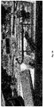
- a bent flexible drive shaft comprises incoming and outgoing portions in essence parallel to a common length direction and a bent portion in between.
- the bent portion comprises a displacement Y perpendicular to the length direction realized over a length X in the length direction.
- the motor and the torque sensor were placed on two different platforms that could move relative to each other in a two-dimensional Cartesian plane.
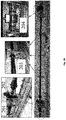
- holder plates were evenly distributed along the shaft to hold it in place and maintain a desired configuration during the experiments, see Figure 5B .
- the motor was again operated as noted in preceding paragraph 1.3 of Example 1.
- Figure 6 shows the torque - deflection angle relationship for the first shaft under different bend radii R (in mm).
- the bending deformation information may comprise a bend angle ⁇ , as indicated in Figure 5C .
- the bend angle may be measured via a rotational encoder (504), such as a rotational optical encoder.
- the experimental setup further comprises a torque sensor (502), a drive unit (507), and a flexible shaft (506).
- the setup may model a knee joint (501) with a thigh (505) and a shank (503).
- Flexible drive shafts are non-ideal torsion springs.
- the output torque vs. deflection angle relationship of flexible drive shafts depends on the torsional deflection angle and the bend angle. In addition, the relationship is non-symmetrical. Surprisingly, these relationships of flexible drive shafts show a high repeatability regardless of the amplitude or frequency of the setpoint command.
- a two-component model comprising a negative component for negative deflection angles and a positive component for positive deflection angles.
- ⁇ ⁇ m - ⁇ s
- Table 1 comprises fitted model coefficients for the first and second flexible drive shafts.
- the corresponding experimental and model torque-angle relationships of the first and second flexible drive shafts are shown in Figures 7A (first flex. shaft) and 7B (second flex. shaft).
- the model shows a root mean square error of 0.029 ⁇ 0.017 N.m with respect to the torque values provided by the torque sensor.
- the normalized root mean square error is 0.315 ⁇ 0.188%, with maximum observed values of 1.27%.
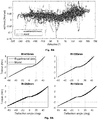
- the corresponding experimental and model quasi-stiffness-angle relationships of the first and second flexible drive shafts are shown in Figures 8A (first flex. shaft) and 8B (second flex. shaft).
- Table 1 - Fitted model coefficients for the first and second flexible drive shafts First flex.
- Table 2 and Figure 9B comprise fitted bending deformation prefactors ⁇ (R) at various bend radii R for the first flexible drive shaft, as well as the corresponding normalized root mean square errors between the experimental data and the model predictions.
- the corresponding experimental and model torque-angle relationships of the first flexible drive shaft are shown in Figure 9A for various values of the bend radius R.
- Figure 11 shows a cascade control system comprising an inner velocity control loop performed at the motor controller (EPOS3) and an outer PID torque control loop.
- Figure 14 shows the performance of the implemented controller when following a desired sinusoidal signal with an amplitude of 6 N.m and a frequency of 1 Hz.
- the tracking error shows a mean value (RMSE) of 0.7334 ⁇ 0.0223 N.m for a set of 15 iterations, corresponding to a normalized error (NRMSE) of 6.11%, with a mean delay of 25 ms.
- RMSE mean value
- NAMSE normalized error
- the mean error in accuracy between the torque estimation and the torque sensor is 0.0456 ⁇ 0.005 N.m (0.37%).
- Example 3 Impedance of a flexible drive shaft at zero torque control
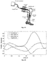
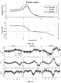
- Output impedance was calculated as the transfer function between the interaction torque (provided by the estimation) and the output velocity generated by the load motor, for three different conditions: straight shaft and bend radii of 450 and 200 mm. This way, the influence of bend radius on the output impedance was characterized. As Figure 16 shows, the controller is able to render impedances close to zero for low frequencies regardless of the bend radius. As the frequency is increased, the controller cannot fully follow the desired output impedance and starts to display higher ones, until the resonance point is reached and the output impedance becomes the mechanical impedance of the flexible shaft. This output impedance increases more for lower bend radius. In addition, the maximum impedance value (resonance point) is achieved at lower frequencies as the cable is bent.
- the output impedance of the flexible drive shaft depends not only on the controller, but also on the spatial configuration of the flexible drive shaft, due to the increase in friction with bend radius.
- the flexible drive shaft therefore behaves as a variable stiffness actuator, as its output stiffness depends on the spatial configuration of the flexible shaft.
- Example 4 Flexible drive shaft with transmission system at an output joint
- output velocity is reduced and output stiffness enlarged, limiting the compliant properties of the actuator and reducing the accuracy of the torque controller due to possible backlash or losses in the transmission system.
- the output stiffness is increased by the square of the transmission ratio, increasing the output impedance of the device, losing the compliant properties of the actuator, and turning it into a stiff actuator.
- a gearbox with transmission ratio 9:1 was placed at the distal end of the flexible drive shaft.
- the gearbox was connected to a torque sensor in order to measure the generated output torque.
- the transmission sensor can be taken into account multiplicatively in the torque model, and again good correspondence of measured and predicted torques was obtained.
- the bend angle ⁇ instead of the bend radius R is used to characterize the bending deformation, see Figure 5C .
- the motor (507) and the torque sensor (502) are placed in two different aluminum profiles that act as the thigh (505) and the shank (503), respectively, connected by a passive hinge joint which acts as the knee joint (501).
- the flexible drive shaft (506) connects the motor with the torque sensor (502), transmitting the torque from the thigh to the ankle, spanning through the knee joint.
- a rotational optical encoder (504) measures the rotation angle ⁇ of the knee, providing information of the flexible shaft's bend angle.
- the shaft is rigidly and evenly fixed to the two profiles by means of custom made holding plates.
- the torque controller was set to follow a 1 Hz sinusoidal signal with an amplitude of 4 N.m while the joint's angle was manually changed to fixed angles of 0, 20, 40, 60, 70, 80 and 90 degrees while the output torque was measured by the torque sensor.
- Data were collected and implemented in an offline identification procedure to update the model estimation to consider the bend angle by means of the deformation prefactor ⁇ ( ⁇ ).
- the identified deformation prefactors ( ⁇ ( ⁇ )-values) were introduced into a dynamic lookup table, with linear interpolation for ⁇ ( ⁇ ). This way, the torque estimation was automatically set to be updated as a function of the bend angle, measured by the knee encoder.
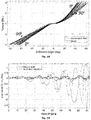
- Figure 19 shows the estimation error as a function of the bend angle
- Figure 20 a corresponding time evolution of the estimation error and the bend angle, both using the proposed dynamic model and without it.
- Maximum estimation error when using the dynamic adaptation was 0.35 N.m, whereas the maximum estimation error in case of neglecting the effect of the bend angle was 2.8 N.m.
- the proposed adaptive model reduces the accuracy error by 87.5% by considering the bend angle.
- Example 6 Sensor cluster for deformation information of the body
- the body is preferably a flexible drive shaft.
- the sensor cluster comprises two rotational encoders for determining the torsional deformation information.
- the rotational encoders are preferably rotational optical encoders, preferably with 2000 counts per turn (CPT). 2000 CPT corresponds to a precision of 0.18°.
- One of the rotational encoders is positioned in series at the proximal end of the body and another of the rotational encoders is positioned in series at the distal end of the body. Based on the signals from the two rotational encoders, the torsional relative angle between the distal end and the proximal end can be determined.
- the sensor cluster comprises one or more bending sensors for determining bending deformation information of the body.
- a bending sensor may hereby be a distance sensors, a displacement sensors, an additional rotational encoder, and the like.
- a bending sensor may directly measure a deformation of the body or may measure a deformation of another component, e.g. the mechanical joint, to which the body is attached. If the body comprises several flexion points along its length (and correspondingly the wearable robot, orthosis or exoskeleton), each of these flexion points may be provided with the necessary bending sensors.
- Figure 21 shows a schematic overview of an embodiment of the device for actuating a joint.
- the device comprises a mechanical joint (175), a motor (171) for providing torque to the mechanical joint (175), a flexible drive shaft (172) in between the motor (171) and the mechanical joint (175) for transmitting torque from the motor (171) to the mechanical joint (175).
- the device further comprises a sensor cluster (173a, 173b, 174).
- the sensor cluster comprises:
- a relative torsional angle of the flexible drive shaft can be obtained.
- bending deformation information of the flexible drive shaft can be obtained, such as, for example, a bending angle ( ⁇ ) or a bending radius.
- the motor may hereby be positioned on the back of a torso (176), while the mechanical joint may be a knee mechanical joint (175) for rotating a lower leg (178) relative to an upper leg (177).
- the motor is driven based on a non-linear torque model (185; see Figure 18 ) to calculate an input, preferably an input velocity, such as a motor velocity, at the proximal end of the flexible drive shaft (186) based on a desired output torque at the distal end of the flexible drive shaft (182) and the torsional relative angle and bending deformation information of the flexible drive shaft (184).
- a non-linear torque model 185; see Figure 18
- an input velocity such as a motor velocity
Landscapes
- Engineering & Computer Science (AREA)
- Health & Medical Sciences (AREA)
- Robotics (AREA)
- Mechanical Engineering (AREA)
- Life Sciences & Earth Sciences (AREA)
- Animal Behavior & Ethology (AREA)
- General Health & Medical Sciences (AREA)
- Public Health (AREA)
- Veterinary Medicine (AREA)
- Orthopedic Medicine & Surgery (AREA)
- Biomedical Technology (AREA)
- Heart & Thoracic Surgery (AREA)
- Vascular Medicine (AREA)
- Nursing (AREA)
- Epidemiology (AREA)
- Human Computer Interaction (AREA)
- Rehabilitation Therapy (AREA)
- Physical Education & Sports Medicine (AREA)
- Pain & Pain Management (AREA)
- Pathology (AREA)
- Surgery (AREA)
- Molecular Biology (AREA)
- Medical Informatics (AREA)
- Biophysics (AREA)
- Physics & Mathematics (AREA)
- Manipulator (AREA)
- Flexible Shafts (AREA)
Priority Applications (8)
| Application Number | Priority Date | Filing Date | Title |
|---|---|---|---|
| EP18167799.8A EP3556518A1 (de) | 2018-04-17 | 2018-04-17 | Dezentraler drehantrieb |
| PCT/EP2019/059900 WO2019201982A1 (en) | 2018-04-17 | 2019-04-17 | Decentralized rotary actuator |
| JP2020556238A JP2021529673A (ja) | 2018-04-17 | 2019-04-17 | 分散型ロータリーアクチュエータ |
| EP19717324.8A EP3781360B1 (de) | 2018-04-17 | 2019-04-17 | Dezentraler drehantrieb |
| EP23220789.4A EP4324435A3 (de) | 2018-04-17 | 2019-04-17 | Dezentraler drehsteller |
| KR1020207029404A KR20200143681A (ko) | 2018-04-17 | 2019-04-17 | 분산식 회전 액츄에이터 |
| CN201980025633.9A CN111989192B (zh) | 2018-04-17 | 2019-04-17 | 非集中式旋转致动器 |
| US17/047,164 US12226906B2 (en) | 2018-04-17 | 2019-04-17 | Decentralized rotary actuator |
Applications Claiming Priority (1)
| Application Number | Priority Date | Filing Date | Title |
|---|---|---|---|
| EP18167799.8A EP3556518A1 (de) | 2018-04-17 | 2018-04-17 | Dezentraler drehantrieb |
Publications (1)
| Publication Number | Publication Date |
|---|---|
| EP3556518A1 true EP3556518A1 (de) | 2019-10-23 |
Family
ID=62067359
Family Applications (3)
| Application Number | Title | Priority Date | Filing Date |
|---|---|---|---|
| EP18167799.8A Withdrawn EP3556518A1 (de) | 2018-04-17 | 2018-04-17 | Dezentraler drehantrieb |
| EP23220789.4A Pending EP4324435A3 (de) | 2018-04-17 | 2019-04-17 | Dezentraler drehsteller |
| EP19717324.8A Active EP3781360B1 (de) | 2018-04-17 | 2019-04-17 | Dezentraler drehantrieb |
Family Applications After (2)
| Application Number | Title | Priority Date | Filing Date |
|---|---|---|---|
| EP23220789.4A Pending EP4324435A3 (de) | 2018-04-17 | 2019-04-17 | Dezentraler drehsteller |
| EP19717324.8A Active EP3781360B1 (de) | 2018-04-17 | 2019-04-17 | Dezentraler drehantrieb |
Country Status (6)
| Country | Link |
|---|---|
| US (1) | US12226906B2 (de) |
| EP (3) | EP3556518A1 (de) |
| JP (1) | JP2021529673A (de) |
| KR (1) | KR20200143681A (de) |
| CN (1) | CN111989192B (de) |
| WO (1) | WO2019201982A1 (de) |
Cited By (4)
| Publication number | Priority date | Publication date | Assignee | Title |
|---|---|---|---|---|
| CN113069253A (zh) * | 2021-04-28 | 2021-07-06 | 祖大飞 | 一种机械义肢 |
| CN113183119A (zh) * | 2021-02-26 | 2021-07-30 | 北京大学 | 基于绳驱动冗余柔性驱动器的可穿戴下肢外骨骼机器人 |
| US20230271326A1 (en) * | 2022-02-28 | 2023-08-31 | X Development Llc | Control system for exosuits |
| WO2025093775A1 (en) | 2023-11-02 | 2025-05-08 | Vrije Universiteit Brussel | An exoskeleton for musculoskeletal support and assistance |
Families Citing this family (7)
| Publication number | Priority date | Publication date | Assignee | Title |
|---|---|---|---|---|
| WO2013188510A2 (en) * | 2012-06-12 | 2013-12-19 | Iwalk, Inc. | Prosthetic, orthotic or exoskeleton device |
| EP3556518A1 (de) | 2018-04-17 | 2019-10-23 | Vrije Universiteit Brussel | Dezentraler drehantrieb |
| CN114690516B (zh) * | 2020-12-28 | 2024-03-22 | 苏州佳世达光电有限公司 | 一种投影装置 |
| CN115070823B (zh) * | 2022-06-21 | 2023-09-29 | 法奥意威(苏州)机器人系统有限公司 | 关节刚度检测方法、机器人运动控制方法及相关装置 |
| CN115556084B (zh) * | 2022-11-01 | 2025-06-13 | 佗道医疗科技有限公司 | 一种输入轴的半径确定方法、柔性臂机器人及控制方法 |
| CN117226852B (zh) * | 2023-11-10 | 2024-01-26 | 西南交通大学 | 软体外骨骼控制方法及装置 |
| JP2025149145A (ja) * | 2024-03-26 | 2025-10-08 | 本田技研工業株式会社 | 伝達機構及びロボット |
Citations (5)
| Publication number | Priority date | Publication date | Assignee | Title |
|---|---|---|---|---|
| US20110040216A1 (en) | 2005-03-31 | 2011-02-17 | Massachusetts Institute Of Technology | Exoskeletons for running and walking |
| US9266233B2 (en) * | 2013-03-15 | 2016-02-23 | Sri International | Exosuit system |
| US9498401B2 (en) * | 2011-12-20 | 2016-11-22 | Massachusetts Institute Of Technology | Robotic system for simulating a wearable device and method of use |
| WO2016204441A1 (ko) * | 2015-06-15 | 2016-12-22 | 에스지메카트로닉스 | 다관절 로봇의 구동장치 |
| US20170242477A1 (en) * | 2013-07-05 | 2017-08-24 | Axonvr Corporation | Whole-body human-computer interface |
Family Cites Families (7)
| Publication number | Priority date | Publication date | Assignee | Title |
|---|---|---|---|---|
| US20110313331A1 (en) * | 2009-02-10 | 2011-12-22 | Bruno Marc Florent Victore Dehez | Rehabilitation Robot |
| CN101518472B (zh) * | 2009-03-24 | 2011-02-02 | 中国人民解放军海军航空工程学院 | 下肢智能携行外骨骼系统及其控制方法 |
| US8403870B2 (en) * | 2009-09-15 | 2013-03-26 | Covidien Lp | Portable, self-contained compression device |
| MX2014011131A (es) * | 2012-03-22 | 2015-06-02 | Ekso Bionics Inc | Interconexion maquina-persona para aparatos ortopedicos de extremidad inferior. |
| FR2990485B1 (fr) * | 2012-05-09 | 2021-04-23 | Commissariat Energie Atomique | Arbre de transmission flexible, et verin a cable a moteur deporte utilisant un tel arbre |
| CN108349064B (zh) * | 2015-09-01 | 2020-07-14 | 南洋理工大学 | 在接触任务中监测互动动态的仪表化工具 |
| EP3556518A1 (de) | 2018-04-17 | 2019-10-23 | Vrije Universiteit Brussel | Dezentraler drehantrieb |
-
2018
- 2018-04-17 EP EP18167799.8A patent/EP3556518A1/de not_active Withdrawn
-
2019
- 2019-04-17 EP EP23220789.4A patent/EP4324435A3/de active Pending
- 2019-04-17 US US17/047,164 patent/US12226906B2/en active Active
- 2019-04-17 JP JP2020556238A patent/JP2021529673A/ja active Pending
- 2019-04-17 WO PCT/EP2019/059900 patent/WO2019201982A1/en not_active Ceased
- 2019-04-17 EP EP19717324.8A patent/EP3781360B1/de active Active
- 2019-04-17 KR KR1020207029404A patent/KR20200143681A/ko not_active Withdrawn
- 2019-04-17 CN CN201980025633.9A patent/CN111989192B/zh active Active
Patent Citations (5)
| Publication number | Priority date | Publication date | Assignee | Title |
|---|---|---|---|---|
| US20110040216A1 (en) | 2005-03-31 | 2011-02-17 | Massachusetts Institute Of Technology | Exoskeletons for running and walking |
| US9498401B2 (en) * | 2011-12-20 | 2016-11-22 | Massachusetts Institute Of Technology | Robotic system for simulating a wearable device and method of use |
| US9266233B2 (en) * | 2013-03-15 | 2016-02-23 | Sri International | Exosuit system |
| US20170242477A1 (en) * | 2013-07-05 | 2017-08-24 | Axonvr Corporation | Whole-body human-computer interface |
| WO2016204441A1 (ko) * | 2015-06-15 | 2016-12-22 | 에스지메카트로닉스 | 다관절 로봇의 구동장치 |
Non-Patent Citations (1)
| Title |
|---|
| M. R. TUCKER ET AL.: "Design of a wearable perturbator for human knee impedance estimation during gait", IEEE INTERNATIONAL CONFERENCE ON REHABILITATION ROBOTICS (ICORR), 2013, Retrieved from the Internet <URL:http://dx.doi.org/10.1109/ICORR.2013.6650372> |
Cited By (6)
| Publication number | Priority date | Publication date | Assignee | Title |
|---|---|---|---|---|
| CN113183119A (zh) * | 2021-02-26 | 2021-07-30 | 北京大学 | 基于绳驱动冗余柔性驱动器的可穿戴下肢外骨骼机器人 |
| CN113183119B (zh) * | 2021-02-26 | 2022-05-31 | 北京大学 | 基于绳驱动冗余柔性驱动器的可穿戴下肢外骨骼机器人 |
| CN113069253A (zh) * | 2021-04-28 | 2021-07-06 | 祖大飞 | 一种机械义肢 |
| US20220346980A1 (en) * | 2021-04-28 | 2022-11-03 | Dafei Zu | Mechanical prosthetic limb |
| US20230271326A1 (en) * | 2022-02-28 | 2023-08-31 | X Development Llc | Control system for exosuits |
| WO2025093775A1 (en) | 2023-11-02 | 2025-05-08 | Vrije Universiteit Brussel | An exoskeleton for musculoskeletal support and assistance |
Also Published As
| Publication number | Publication date |
|---|---|
| US20210122040A1 (en) | 2021-04-29 |
| KR20200143681A (ko) | 2020-12-24 |
| EP4324435A2 (de) | 2024-02-21 |
| CN111989192A (zh) | 2020-11-24 |
| EP3781360B1 (de) | 2024-01-03 |
| CN111989192B (zh) | 2025-04-08 |
| EP3781360C0 (de) | 2024-01-03 |
| US12226906B2 (en) | 2025-02-18 |
| EP3781360A1 (de) | 2021-02-24 |
| EP4324435A3 (de) | 2024-05-15 |
| JP2021529673A (ja) | 2021-11-04 |
| WO2019201982A1 (en) | 2019-10-24 |
Similar Documents
| Publication | Publication Date | Title |
|---|---|---|
| EP3781360B1 (de) | Dezentraler drehantrieb | |
| Stienen et al. | Design of a rotational hydroelastic actuator for a powered exoskeleton for upper limb rehabilitation | |
| US9802323B2 (en) | Secured motor-driven articulated arm with cable capstan | |
| Nasr et al. | Optimal design of active-passive shoulder exoskeletons: A computational modeling of human-robot interaction | |
| dos Santos et al. | Impedance control of a rotary series elastic actuator for knee rehabilitation | |
| Jeong et al. | Feedforward friction compensation of Bowden-cable transmission via loop routing | |
| Jeong et al. | Investigation on the control strategy of soft wearable robotic hand with slack enabling tendon actuator | |
| Jeong et al. | Control of a Bowden-cable actuation system with embedded BoASensor for soft wearable robots | |
| Manfredi et al. | Low power consumption mini rotary actuator with SMA wires | |
| Friedl et al. | Wrist and forearm rotation of the DLR hand arm system: Mechanical design, shape analysis and experimental validation | |
| Rodriguez-Cianca et al. | A flexible shaft-driven remote and torsionally compliant actuator (rtca) for wearable robots | |
| Chiang et al. | Tendon sheath analysis for estimation of distal end force and elongation | |
| Cherelle et al. | The MACCEPA actuation system as torque actuator in the gait rehabilitation robot ALTACRO | |
| WO2022216227A1 (en) | Cable-driven movement assistance apparatus for human lower limb | |
| KR101691941B1 (ko) | 로봇용 관절 구동장치 및 로봇용 관절 구동장치의 관절 토크 측정 방법 | |
| Lee et al. | Human force observation and assistance for lower limb rehabilitation using wire-driven series elastic actuator | |
| Zhang et al. | Mechanical design and control method for sea and VSA-based exoskeleton devices for elbow joint rehabilitation | |
| Blumenschein et al. | A cable-based series elastic actuator with conduit sensor for wearable exoskeletons | |
| Vitiello et al. | A sensorless torque control for Antagonistic Driven Compliant Joints | |
| Zhang et al. | Torque estimation technique of robotic joint with harmonic drive transmission | |
| Inoue et al. | Robotic joint design by agonist and antagonist arrangement with twisting small-diameter round-belts | |
| Feng et al. | Variable tensile stiffness pneumatic actuators with adjustable stick-slip friction of soft-tooth structures | |
| JP7529599B2 (ja) | ロボット | |
| US20240238980A1 (en) | Control system for controlling a surgical robot arm | |
| Chiaradia et al. | Rigid versus soft exoskeletons: interaction strategies for upper limb assistive technology |
Legal Events
| Date | Code | Title | Description |
|---|---|---|---|
| PUAI | Public reference made under article 153(3) epc to a published international application that has entered the european phase |
Free format text: ORIGINAL CODE: 0009012 |
|
| STAA | Information on the status of an ep patent application or granted ep patent |
Free format text: STATUS: THE APPLICATION HAS BEEN PUBLISHED |
|
| AK | Designated contracting states |
Kind code of ref document: A1 Designated state(s): AL AT BE BG CH CY CZ DE DK EE ES FI FR GB GR HR HU IE IS IT LI LT LU LV MC MK MT NL NO PL PT RO RS SE SI SK SM TR |
|
| AX | Request for extension of the european patent |
Extension state: BA ME |
|
| STAA | Information on the status of an ep patent application or granted ep patent |
Free format text: STATUS: THE APPLICATION IS DEEMED TO BE WITHDRAWN |
|
| 18D | Application deemed to be withdrawn |
Effective date: 20200603 |