EP3556512B1 - Cut-off machine - Google Patents
Cut-off machine Download PDFInfo
- Publication number
- EP3556512B1 EP3556512B1 EP19167037.1A EP19167037A EP3556512B1 EP 3556512 B1 EP3556512 B1 EP 3556512B1 EP 19167037 A EP19167037 A EP 19167037A EP 3556512 B1 EP3556512 B1 EP 3556512B1
- Authority
- EP
- European Patent Office
- Prior art keywords
- guard
- movable
- coupling member
- blade
- rotary shaft
- Prior art date
- Legal status (The legal status is an assumption and is not a legal conclusion. Google has not performed a legal analysis and makes no representation as to the accuracy of the status listed.)
- Active
Links
Images


Classifications
-
- B—PERFORMING OPERATIONS; TRANSPORTING
- B27—WORKING OR PRESERVING WOOD OR SIMILAR MATERIAL; NAILING OR STAPLING MACHINES IN GENERAL
- B27G—ACCESSORY MACHINES OR APPARATUS FOR WORKING WOOD OR SIMILAR MATERIALS; TOOLS FOR WORKING WOOD OR SIMILAR MATERIALS; SAFETY DEVICES FOR WOOD WORKING MACHINES OR TOOLS
- B27G19/00—Safety guards or devices specially adapted for wood saws; Auxiliary devices facilitating proper operation of wood saws
- B27G19/02—Safety guards or devices specially adapted for wood saws; Auxiliary devices facilitating proper operation of wood saws for circular saws
- B27G19/04—Safety guards or devices specially adapted for wood saws; Auxiliary devices facilitating proper operation of wood saws for circular saws for manually-operated power-driven circular saws
-
- B—PERFORMING OPERATIONS; TRANSPORTING
- B23—MACHINE TOOLS; METAL-WORKING NOT OTHERWISE PROVIDED FOR
- B23D—PLANING; SLOTTING; SHEARING; BROACHING; SAWING; FILING; SCRAPING; LIKE OPERATIONS FOR WORKING METAL BY REMOVING MATERIAL, NOT OTHERWISE PROVIDED FOR
- B23D45/00—Sawing machines or sawing devices with circular saw blades or with friction saw discs
- B23D45/16—Hand-held sawing devices with circular saw blades
-
- B—PERFORMING OPERATIONS; TRANSPORTING
- B28—WORKING CEMENT, CLAY, OR STONE
- B28D—WORKING STONE OR STONE-LIKE MATERIALS
- B28D7/00—Accessories specially adapted for use with machines or devices of the preceding groups
- B28D7/02—Accessories specially adapted for use with machines or devices of the preceding groups for removing or laying dust, e.g. by spraying liquids; for cooling work
Definitions
- the present disclosure relates to a cut-off machine according to the preamble of claim 1.
- a cut-off machine is disclosed in US 4 774 866 A .
- Japanese Examined Patent Publication No. H07-14570 discloses a cutting tool which includes a circular cutting blade and a safety cover which covers the circular cutting blade with only a portion of a cutting edge of the circular cutting blade exposed.
- the safety cover is divided into a safety cover body and a movable body, and a spring is interposed between the safety cover body and the movable body.
- the circular blade (circular cutting blade) is clamped between a pair of holding members each having an annular shape and is held by a rotary shaft, and the rotary shaft is rotatably supported on a fixed guard (the safety cover body) which covers part of an outer periphery of the blade.
- a movable guard (the movable body) is coupled to the fixed guard such that the movable guard which movably covers part of the outer periphery of the blade can be turned around the rotary shaft.
- a maximum cutting depth of the blade becomes shallow.
- the present invention provides a cut-off machine according to claim 1.
- This cut-off machine includes: a rotary shaft; a blade having a circular shape, and having, in a central portion thereof, an insertion hole in which the rotary shaft is inserted; a holding mechanism configured to hold the blade with respect to the rotary shaft, and including a pair of holding members which each has an annular shape and which clamp the blade therebetween; a fixed guard configured to cover a portion of an outer periphery of the blade, and including a fixed support which is provided with a bearing portion rotatably supporting the rotary shaft; a movable guard configured to movably cover a portion of the outer periphery of the blade, the portion being circumferentially adjacent to the portion covered with the fixed guard, the movable guard having a movable base formed to surround a periphery of the rotary shaft; and a coupling mechanism configured to couple the movable guard to the fixed guard such that the movable guard can be turned around the rotary shaft, and including
- the movable base is formed such that the inner peripheral edge of the movable base is located closer to the rotary shaft than the coupling bolt is.
- This configuration makes it possible to expand, radially inwardly (i.e., toward the shaft center of the rotary shaft), the portion serving as the receiving surface for the movable guard to a greater extent than in a case where the inner peripheral edge of a movable guard is located remoter from the rotary shaft than the coupling bolt is.
- a length of the receiving surface for the movable guard (a length in the radial direction of the portion serving as the receiving surface for the movable guard) can be increased so as not to expand the portion serving as the receiving surface for the movable guard (in particular, a portion which faces a cutting target when the blade cuts the cutting target) outward in the radial direction (or so as to reduce the outward expansion in the radial direction).
- This feature makes it possible to increase the length of the receiving surface for the movable guard while reducing a decrease in a maximum cutting depth of the blade.
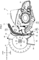
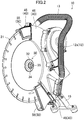
- FIGS. 1 to 3 exemplifies an external appearance of a cut-off machine 10 according to a first embodiment.
- the cut-off machine 10 includes a circular blade which can be rotationally driven by a drive source such as an engine, and is configured to cut a cutting target (for example, a concrete body) with the circular blade that is being rotationally driven.
- the cut-off machine 10 is embodied as a handheld cut-off machine (the so-called engine cut-off machine), and configured such that a worker operates the cut-off machine 10 while holding the cut-off machine 10 with both hands.
- the cut-off machine 10 includes a rotary shaft 20, a blade 21, a holding mechanism 30, a fixed guard 40, a movable guard 50, a coupling mechanism 60, a housing 11, a dust collecting mechanism 12, a first handle 13, a second handle 14, and a leg 15.
- a posture in which the cut-off machine 10 is placed on the ground (a horizontal surface) is defined as the reference posture of the cut-off machine 10, and directions relating to the cut-off machine 10 are defined based on a case where the cut-off machine 10 placed on the ground is viewed from the blade 21.
- directions upper, lower, right, left, front, and rear directions
- FIG. 1 For example, in FIG. 1
- the right-to-left direction on a plane of paper corresponds to the front-to-rear direction
- a side on the plane of paper facing the viewer corresponds to the right side
- a side on the plane of paper facing away from the viewer corresponds to the left side
- the rotary shaft 20 is configured to be rotationally driven by power of the later-described drive source (not shown).
- the rotary shaft 20 is rotatably supported on the fixed guard 40.
- the rotary shaft 20 is supported such that a shaft center O extends in the right-to-left direction.
- the blade 21 has a circular shape.
- the blade 21 has, in a central portion thereof, an insertion hole 201 into which the rotary shaft 20 is inserted.
- the blade 21 is comprised of a diamond blade.
- a counterclockwise direction in FIG. 1 is denoted as a normal rotation direction of the blade 21 (for example, a direction in which the blade 21 rotates to cut a cutting target), and a direction reverse to the normal rotation direction (a clockwise direction in FIG. 1 ) is denoted as a reverse rotation direction.
- the holding mechanism 30 is configured to hold the blade 21 with respect to the rotary shaft 20.
- the holding mechanism 30 holds the blade 21 with respect to the rotary shaft 20 in a detachable manner.
- the blade 21 held with respect to the rotary shaft 20 via the holding mechanism 30 is rotationally driven together with the rotary shaft 20. Note that a configuration of the holding mechanism 30 will be described later in detail.
- the fixed guard 40 is configured to cover a portion of an outer periphery of the blade 21.
- the movable guard 50 is configured to movably cover another portion, of the outer periphery of the blade 21, which is circumferentially adjacent to the portion covered with the fixed guard 40.
- the coupling mechanism 60 is configured to couple the movable guard 50 to the fixed guard 40 such that the movable guard 50 can be turned around the rotary shaft 20.
- the fixed guard 40 covers a rear side of the blade 21, and the movable guard 50 covers an upper portion and a lower portion of the blade 21, whereas a front portion of the blade 21 is exposed. Note that configurations of the fixed guard 40, the movable guard 50, and the coupling mechanism 60 will be described later in detail.
- the housing 11 houses the drive source (not shown) such as the engine.
- the housing 11 and the fixed guard 40 are coupled to each other.
- a power transmission mechanism for example, a combination of gears, pulleys, belts, and the like; not shown
- the power of the drive source is transmitted via the power transmission mechanism to the rotary shaft 20 and the dust collecting mechanism 12, and thus, the rotary shaft 20 is rotationally driven and the dust collecting mechanism 12 operates.
- the dust collecting mechanism 12 is configured to collect and accumulate dust particles generated in cutting a cutting target (for example, a concrete body or the like).
- the dust collecting mechanism 12 includes a dust collecting fan 12a and a dust collecting hose 12b.
- a suction inlet of the dust collecting fan 12a communicates with an inside of the fixed guard 40, and a blowout outlet of the dust collecting fan 12a communicates with one end of the dust collecting hose 12b.
- the dust collecting fan 12a is configured to be driven by the power of the drive source (not shown) housed in the housing 11 so as to suck air from the inside of the fixed guard 40 through the suction inlet and blow out the sucked air to the dust collecting hose 12b through the blowout outlet.
- One end of the dust collecting hose 12b is connected to the blowout outlet of the dust collecting fan 12a, and the other end of the dust collecting hose 12b is connected to a dust collecting bag (that is, a bag for collecting and accumulating the dust particles; not shown).
- a dust collecting bag that is, a bag for collecting and accumulating the dust particles; not shown.
- the first handle 13 extends from an upper left portion of the fixed guard 40, passes above a rear portion of the fixed handle 40, and reaches a lower right portion of the fixed guard 40.
- the second handle 14 is provided on a rear portion of the housing 11.
- the leg 15 is provided on a lower portion of the fixed guard 40.
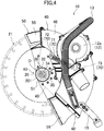
- FIG. 4 is a side view illustrating the cut-off machine 10 with the blade 21 detached (i.e., a plan view viewed from a later-described second fixed-guard part 46).
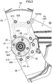
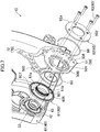
- FIG. 5 is a side view illustrating, on an enlarged scale, a configuration of the coupling mechanism 60 and the vicinity thereof (i.e., a plan view viewed from the later-described second fixed-guard part 46).
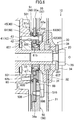
- FIG. 6 is a cross-sectional view taken along line A-O-B in FIG. 5 .
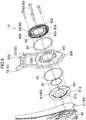
- FIGS. 7 and 8 is an exploded perspective view of the configuration of the coupling mechanism 60 and the vicinity thereof.
- FIG. 4 is a side view illustrating the cut-off machine 10 with the blade 21 detached (i.e., a plan view viewed from a later-described second fixed-guard part 46).
- FIG. 5 is a side view illustrating, on an enlarged scale, a configuration of the coupling mechanism 60 and the vicinity thereof (i.e., a plan view viewed from the
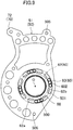
- FIG. 9 is a side view illustrating a configuration of a later-described movable base 51, a second coupling member 62, and coupling bolts 63 (i.e., a plan view viewed from the later-described second fixed-guard part 46).
- the holding mechanism 30 is configured to hold the blade 21 with respect to the rotary shaft 20.
- the holding mechanism 30 includes a pair of holding members (first and second holding members 31 and 32), a fixing member 33, a washer 34, and a mounting bolt 35.
- Each of the first and second holding members 31 and 32 has an annular shape.
- the first and second holding members 31 and 32 sandwich the blade 21 therebetween.
- the first holding member 31 is disposed on a side of the blade 21, which is adjacent to the coupling mechanism 60 (specifically, on the left side)
- the second holding member 32 is disposed on a side of the blade 21, which is remote from the coupling mechanism 60 (specifically, on the right side).
- the fixing member 33 has an annular shape, and is fixed while the rotary shaft 20 passes through the fixing member 33.
- the washer 34 has an annular shape.
- the pair of holding members (first and second holding members 31 and 32) is sandwiched between the washer 34 and the fixing member 33.
- the first holding member 31 is disposed between the fixing member 33 and the blade 21
- the second holding member 32 is disposed between the blade 21 and the washer 34
- the mounting bolt 35 is inserted into the washer 34 and is screwed into the rotary shaft 20.
- screwing the mounting bolt 35 into the rotary shaft 20 causes the first and second holding members 31 and 32 to be clamped tightly by the fixing member 33 and the washer 34, and the blade 21 to be clamped tightly by the first and second holding members 31 and 32.
- the rotary shaft 20 can be held with respect to the blade 21.
- loosening the mounting bolt 35 screwed into the rotary shaft 20 reduces the tightness with which the first and second holding members 31 and 32 is clamped by the fixing member 33 and the washer 34, and the tightness with which the blade 21 is clamped by the first and second holding members 31 and 32. In this manner, the blade 21 can be detached from the rotary shaft 20.
- a holding ring 36 having an annular shape is provided between an outer peripheral surface of the rotary shaft 20 and an inner peripheral surface of the insertion hole 201 of the blade 21.
- the rotary shaft 20 is fitted into the holding ring 36, and the holding ring 36 is fitted into the insertion hole 201 of the blade 21.
- the fixed guard 40 is configured to cover a portion of the outer periphery of the blade 21 (in this example, a rear portion of the blade 21).
- the fixed guard 40 includes a fixed support 41, a first fixed-guard part 45, and a second fixed-guard part 46.
- the fixed guard 40 is made of a light alloy such as an aluminum alloy.
- the fixed support 41 has a bearing portion 42.
- the bearing portion 42 is configured to rotatably support the rotary shaft 20.
- the fixed support 41 is disposed adjacent to an end surface (left side) of the blade 21.
- the fixed support 41 has a cylindrical shape, and the bearing portion 42 is disposed in a central portion of the fixed support 41.
- the fixing member 33, the first holding member 31, the blade 21, the second holding member 32, and the washer 34 are arranged sequentially in a direction from the bearing portion 42 of the fixed support 41 toward the mounting bolt 35.
- the first fixed-guard part 45 extends from the fixed support 41 outward in a radial direction so as to cover a portion of the blade 21.
- the first fixed-guard part 45 is disposed adjacent to one end surface (left side) of the blade 21.
- the first fixed-guard part 45 has a fan shape of which the center corresponds to the rotary shaft 20, and the outer peripheral edge thereof is located outside in a radial direction with respect to the outer peripheral edge of the blade 21 (i.e., located further remote from the shaft center O of the rotary shaft 20).
- the fixed support 41 and the first fixed-guard part 45 are formed integrally with each other.
- the second fixed-guard part 46 is disposed so as to face the first fixed-guard part 45 in the axial direction of the rotary shaft 20, has an outer peripheral edge coupled to the outer peripheral edge of the first fixed-guard part 45.
- the second fixed-guard part 46 is disposed adjacent to the other end surface (the right side) of the blade 21.
- the second fixed-guard part 46 has an arc shape so as to extend along the outer peripheral edge of the first fixed-guard part 45 around the rotary shaft 20.
- the first fixed-guard part 45 is provided with a coupling portion 47.
- the coupling part 47 is coupled to the housing 11, and houses therein part of the above-described power transmission mechanism (that transmits the power of the drive source housed in the housing 11 to the rotary shaft 20 supported on the bearing portion 42 and the dust collecting mechanism 12).
- a reinforcing part 48 is provided on a circumferential end portion of the fixed guard 40 (specifically, an upstream end portion in the normal rotation direction). Note that it is preferable that the reinforcing part 48 is made of a material (for example, iron) which is stronger than the material (for example, a light alloy) forming the fixed guard 40.
- the movable guard 50 is configured to movably cover portions of the outer periphery of the blade 21, which are each adjacent to the portion covered with the fixed guard 40 in the circumferential direction of the blade 21 (in this example, an upper portion and a lower portion of the blade 21).
- the movable guard 50 includes a movable base 51, a first movable-guard part 55, and a second movable-guard part 56.
- the first movable-guard part 55 and the second movable-guard part 56 are each made of a light alloy such as an aluminum alloy.
- the movable base 51 is made of a material (for example, iron) which is stronger than the material forming each of the first movable-guard part 55 and the second movable-guard part 56.
- the movable base 51 is shaped so as to surround the periphery of the rotary shaft 20.
- the movable base 51 has a plate shape having an opening 500 formed in a central portion thereof.
- the opening 500 passes through the movable base 51 in an axial direction and has a circular shape surrounding the entire periphery of the rotary shaft 20.
- the rotary shaft 20 and the fixing member 33 are disposed in the opening 500.
- the movable base 51 is formed so as to surround the periphery of the fixing member 33.
- the movable base 51 is provided with a plurality of (specifically, four) slots 501.
- the plurality of slots 501 pass through the movable base 51 in the axial direction.
- Each slot 501 has an arc shape extending along the circumferential direction of the rotary shaft 20.
- the four slots 501 are arranged at 90-degree intervals in the circumferential direction.
- the first movable-guard part 55 extends from the movable base 51 toward one circumferential end portion of the fixed guard 40, and is configured to movably cover a portion of the outer periphery of the blade 21, the portion being adjacent to one circumferential end of the portion covered with the fixed guard 40 (in this example, an upper portion of the blade 21).
- the first movable-guard part 55 is in a plate shape, and has a distal end portion bended in a U-shape so as to cover the portion of the outer periphery of the blade 21 (in this example, the upper portion of the blade 21).
- the first movable-guard part 55 is retractable in the fixed guard 40.
- the second movable-guard part 56 extends from the movable base 51 toward the other circumferential end portion of the fixed guard 40, and is configured to movably cover a portion of the outer periphery of the blade 21, the portion being adjacent to the other circumferential end of the portion covered with the fixed guard 40 (in this example, a lower portion of the blade 21).
- the second movable-guard part 56 is in a plate shape, and has a distal end portion bended in a U-shape so as to cover the portion of the outer periphery of the blade 21 (in this example, the lower portion of the blade 21).
- the second movable-guard part 56 is retractable in the fixed guard 40.
- the first movable-guard part 55 is provided with a first recess 55a into which a portion of the movable base 51 (in this example, an upper end portion) is fitted.
- the first movable-guard part 55 is fixed with a plurality of (in this example, four) first fixing bolts 515 to a portion of the movable base 51 (the portion fitted into the first recess 55a).
- this portion of the movable base 51 (the portion fitted into the first recess 55a) is provided with a plurality of (in this example, four) first fixing bolt holes 505, and the first recess 55a is provided with a plurality of (in this example, four) first communicating holes (not shown) which respectively communicate with the plurality of first fixing bolt holes 505.
- the first fixing bolts 515 are inserted into the first communicating holes of the first movable-guard part 55, and are screwed into the first fixing bolt holes 505 of the movable base 51.
- the second movable-guard part 56 is provided with a second recess 56a into which a portion of the movable base 51 (in this example, a lower end portion) is fitted.
- the second movable-guard part 56 is fixed with a plurality of (in this example, four) second fixing bolts 516 to the portion of the movable base 51 (a portion fitted into the second recess 56a).
- this portion of the movable base 51 (the portion fitted into the second recess 56a) is provided with a plurality of (in this example, four) second fixing bolt holes 506, and the second recess 56a is provided with a plurality of (in this example, four) second communicating holes (not shown) which respectively communicate with the plurality of second fixing bolt holes 506.
- the second fixing bolts 516 are inserted into the second communicating holes of the second movable-guard part 56, and are screwed into the second fixing bolt holes 506 of the movable base 51.
- the coupling mechanism 60 is configured to couple the movable guard 50 to the fixed guard 40 such that the movable guard 50 can be turned around the rotary shaft 20.
- the coupling mechanism 60 includes a first coupling member 61, the second coupling member 62, and the plurality of (in this example, four) coupling bolts 63.
- the first coupling member 61 is disposed between the fixed support 41 and the movable base 51.
- the first coupling member 61 has a first annular part 61a and a first cylindrical part 61b.
- the first annular part 61a is in an annular shape and is disposed between the fixed support 41 and the movable base 51.
- a length between the outer peripheral edge of the first annular part 61a (the first coupling member 61) and the shaft center O of the rotary shaft 20 in a radial direction is equal to or shorter than a length between outer peripheral edges of the first and second holding members 31 and 32 (precisely speaking, one of the outer peripheral edges of the first and second holding members 31 and 32, which is remoter from the shaft center O) and the shaft center O of the rotary shaft 20 in the radial direction.
- the first cylindrical part 61b is in a cylindrical shape, and provided on an inner peripheral edge portion of the first annular part 61a.
- the first cylindrical part 61b projects from the first annular part 61a into an inside of an inner peripheral edge of the movable base 51 (in this example, into the opening 500).
- the first cylindrical part 61b is slidably fitted into the inner peripheral edge (specifically, the opening 500) of the movable base 51, and the inner peripheral surface of the first cylindrical part 61b faces the outer peripheral surface of the fixing member 33.
- the first cylindrical part 61b is formed integrally with the first annular part 61a.
- the first coupling member 61 is provided with a plurality of (in this example, four) first insertion holes 601 which respectively correspond to the plurality of slots 501 of the movable base 51.
- the plurality of first insertion holes 601 pass through the first coupling member 61 (in this example, the first annular part 61a) in the axial direction and respectively communicate with the plurality of slots 501.
- the four first insertion holes 601 are arranged at 90-degree intervals in the circumferential direction.
- the second coupling member 62 is disposed between the movable base 51 and the pair of holding members (in this example, the first holding member 31).
- the movable base 51 is slidably clamped between the second coupling member 62 and the first coupling member 61.
- the second coupling member 62 has a second annular part 62a.
- the second annular part 62a is in an annular shape and is disposed between the movable base 51 and the pair of holding members (in this example, the first holding member 31).
- a length between the outer peripheral edge of the second annular part 62a (second coupling member 62) and the shaft center O of the rotary shaft 20 in a radial direction is equal to or shorter than a length between the outer peripheral edges of the first and second holding members 31 and 32 (precisely speaking, one of the outer peripheral edges of the first and second holding members 31 and 32, which is remoter from the shaft center O) and the shaft center O of the rotary shaft 20 in the radial direction.
- the second annular part 62a and the first annular part 61a face each other with the movable base 51 interposed therebetween.
- the first cylindrical part 61b is fitted into the second annular part 62a.
- the second coupling member 62 has a plurality of (in this example, four) protrusions 62b which respectively correspond to the plurality of slots 501 of the movable base 51.
- the plurality of protrusions 62b respectively protrude into the plurality of slots 501.
- each of the protrusions 62b has an arc shape extending along the slot 501 and protrudes from the second annular part 62a into the slot 501.
- the four protrusions 62b are arranged at 90-degree intervals in the circumferential direction. Note that in this example, the plurality of protrusions 62b are formed integrally with the second annular part 62a.
- each protrusion 62b a portion located radially outside a second insertion hole 602 and a portion located radially inside the associated second insertion hole 602 are cut out.
- each of the protrusions 62b is comprised of two projections which are disposed on both circumferential sides of the second insertion hole 602.
- Each protrusion 62b has a length, in the radial direction, which allows the protrusion 62b to function as a fastening bearing surface for the associated coupling bolt 63 (for example, a length which is equivalent to a diameter of the coupling bolt 63).
- each protrusion 62b in the radial direction is set to be shorter than a length of each slot 501 in the radial direction.
- the length of each protrusion 62b in the radial direction is set to be approximately 4 mm and the length of each slot 501 in the radial direction is set to be approximately 5 mm.
- the length of each protrusion 62b in the radial direction may be longer than, or shorter than, the outer diameter of the threaded portion of each coupling bolt 63.
- the length of the threaded portion of each coupling bolt 63 may be the same as the outer diameter of the threaded portion of each coupling bolt 63.
- the second coupling member 62 is provided with the plurality of (in this example, four) the second insertion holes 602 which respectively correspond to the plurality of slots 501.
- Each of the plurality of second insertion holes 602 passes through the second coupling member 62 (in this example, the second annular part 62a) in the axial direction and is configured to communicate with an associated one of the plurality of slots 501.
- the four second insertion holes 602 are arranged at 90-degree intervals in the circumferential direction.
- each of the plurality of second insertion holes 602 is formed in an associated one of the plurality of protrusions 62b.
- each second insertion hole 602 is formed in a central portion of the associated protrusion 62b in plan view.
- the protrusion 62b is provided.
- the plurality of (in this example, four) coupling bolts 63 fix the first coupling member 61 (in this example, the first coupling member 61 and the second coupling member 62) to the fixed support 41.
- the plurality of coupling bolts 63 are sequentially inserted into the second insertion holes 602, the slots 501, and the first insertion holes 601 and are screwed into the fixed support 41.
- the fixed support 41 is provided with a plurality of (in this example, four) coupling bolt holes 43 which respectively correspond to the plurality of coupling bolts 63.
- the four coupling bolts 63 are screwed into the four coupling bolt holes 43, respectively.
- the coupling bolts 63 which are sequentially inserted into the second insertion holes 602 of the second coupling member 62, the slots 501 of the movable base 51, and the first insertion holes 601 of the first coupling member 61, are screwed into the fixed support 41, thereby allowing the movable base 51 to be slidably clamped between the first coupling member 61 and the second coupling member 62.
- the plurality of coupling bolts 63 is located closer to the rotary shaft 20 than the outer peripheral edges of the first and second holding members 31 and 32 (precisely speaking, one of the outer peripheral edges of the first and second holding members 31 and 32, which is remoter from the shaft center O) are.
- the plurality of coupling bolts 63 is located at a position close to the shaft center O of the rotary shaft 20.
- the inner peripheral edge of the movable base 51 (in this example, the inner peripheral edge of the opening 500) is located closer to the rotary shaft 20 than the plurality of coupling bolts 63 is.
- the cut-off machine 10 includes a first sealing member 65, a second sealing member 66, and a third sealing member 67.
- each of the first, second, and third sealing members 65, 66, and 67 is comprised of an O-ring.
- the first sealing member 65 seals a space between the first coupling member 61 and the movable base 51.
- the first sealing member 65 is in a ring shape.
- a first ring groove 605 into which the first sealing member 65 is fitted is provided in an outer peripheral portion of a surface of the first annular part 61a (in this example, a right end surface), which faces the movable base 51. With this configuration, the space between the first annular part 61a and the movable base 51 is sealed.
- the second sealing member 66 seals a space between the movable base 51 and the second coupling member 62.
- the second sealing member 66 is in a ring shape.
- a second ring groove 606 into which the second sealing member 66 is fitted is provided in an outer peripheral portion of a surface of the second annular part 62a (in this example, the left end surface), which faces the movable base 51. With this configuration, the space between the second annular part 62a and the movable base 51 is sealed.
- the third sealing member 67 seals a space between the first coupling member 61 and the second coupling member 62.
- the third sealing member 67 is in a ring shape.
- a third ring groove 607 into which the third sealing member 67 is fitted is provided in an outer peripheral surface of a distal end portion of the first cylindrical part 61b (in a portion of the outer peripheral surface thereof, which faces the inner peripheral surface of the second annular part 62a). With this configuration, the space between the first cylindrical part 61b and the second annular part 62a is sealed.
- a plurality of (in this example, four) grease grooves 68 are provided in a surface of the second coupling member 62 (specifically, the second annular part 62a), which faces the movable base 51.
- Grease collects in the grease grooves 68.
- each of the grease grooves 68 is in an arc shape extending in the circumferential direction of the rotary shaft 20.
- the four grease grooves 68 are arranged at 90-degree intervals in the circumferential direction. In other words, in this example, the protrusions 62b and the grease grooves 68 alternate each other in the circumferential direction.
- the cut-off machine 10 is further provided with a biasing mechanism 70.
- the biasing mechanism 70 is configured to bias the movable guard 50 in a predetermined rotation direction (in this example, the reverse rotation direction).
- the biasing mechanism 70 includes an elastic member 71, a first engaging part 72, and a second engaging part 73.
- the elastic member 71 is comprised of, for example, an extension coil spring.
- the first engaging part 72 is provided at the movable guard 50 (specifically, the movable base 51) and is engaged with one end of the elastic member 71.
- the second engaging part 73 is provided at the fixed guard 40 (specifically, the first fixed-guard part 45) and is engaged with the other end of the elastic member 71.
- a hook is provided at each of the ends of the elastic member 71.
- the hook provided at the one end of the elastic member 71 is hooked to the first engaging part 72, and the hook provided at the other end of the elastic member 71 is hooked to the second engaging part 73.
- the cut-off machine 10 is provided with a stopper (not shown) which restricts the turn of the movable guard 50.
- the stopper is configured to restrict the turn of the movable guard 50 (specifically, turn in the reverse rotation direction) so as to prevent the first movable-guard part 55 from turning in the reverse rotation direction (in the clockwise direction in FIG. 4 ) beyond a predetermined position of turn.
- a first virtual line L1 is a virtual line which passes through one circumferential end portion (specifically, a downstream end portion in the normal rotation direction) of the first movable-guard part 55 and the shaft center O of the rotary shaft 20 when the second movable-guard part 56 is retracted in the fixed guard 40 and the first movable-guard part 55 is positioned outside the fixed guard 40 (in other words, when the first movable-guard part 55 is in a fully-closed state and the second movable-guard part 56 is in a fully-opened state).
- a second virtual line L2 is a virtual line which passes through the one circumferential end portion of the first movable-guard part 55 and the shaft center O of the rotary shaft 20 when the first movable-guard part 55 is retracted in the fixed guard 40 and the second movable-guard part 56 is positioned outside the fixed guard 40 (in other words, the first movable-guard part 55 is in a fully-opened state and the second movable-guard part 56 is in a fully-closed state).
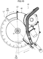
- the movable guard 50 When a user presses the second movable-guard part 56 onto a cutting target in order to cut the cutting target with a lower portion of the blade 21, the movable guard 50 turns in the normal rotation direction (i.e., a counterclockwise direction in FIG. 10 ), against a biasing force (a force biasing the movable guard 50 in the reverse rotation direction) of the biasing mechanism 70. Consequently, the second movable-guard part 56 moves in a direction so as to enter the inside of the fixed guard 40, and at the same time, the first movable-guard part 55 moves in a direction so as to come out of the fixed guard 40. As a result, the lower portion of the blade 21 is exposed while an upper portion of the blade 21 is covered with the first movable-guard part 55.
- the biasing force of the biasing mechanism 70 causes the movable guard 50 to turn in the reverse rotation direction (in a clockwise direction in FIG. 10 ). Consequently, the first movable-guard part 55 moves in a direction so as to enter the inside of the fixed guard 40, and at the same time, the second movable-guard part 56 moves in a direction so as to come out of the fixed guard 40. As a result, the upper portion of the blade 21 is exposed while the lower portion of the blade 21 is covered with the second movable-guard part 56.
- the outer periphery of the blade 21 is covered with the first movable-guard part 55 and the fixed guard 40 in an angular range of 180° or more.
- the outer periphery of the blade 21 is covered with the second movable-guard part 56 and the fixed guard 40 in an angular range of 180° or more.
- the first movable-guard part 55 and the second movable-guard part 56 move complementarily, thereby maintaining a state in which a predetermined angle range of the outer periphery of the blade 21 (in this example, a range of 180° or more) is covered.
- the fixed guard 40 and the movable guard 50 are configured to constantly cover the predetermined angle range of the outer periphery of the blade 21 (in this example, the range of 180° or more).
- cut-off machine 10 of the first embodiment and a cut-off machine of a comparative example (hereinafter, described as the "cut-off machine 90") will be compared and described.
- FIG. 11 exemplifies a configuration of the cut-off machine 90.
- the cut-off machine 90 includes a rotary shaft 91, a blade (not shown), a pair of holding members 92 and 93, a fixed guard 94, a movable guard 95, a coupling member 96, and coupling bolts 97.
- the blade is clamped between the pair of holding members 92 and 93, and is held by the rotary shaft 91.
- the rotary shaft 91 is rotatably supported on the fixed guard 94.
- the movable guard 95 is slidably clamped between the fixed guard 94 and the coupling member 96.
- the coupling member 96 is fixed to the fixed guard 94 with the coupling bolts 97. With this configuration, the movable guard 95 can be turned around the rotary shaft 91.
- the portion serving as the receiving surface for the movable guard 95 corresponds to a portion of the fixed guard 94 and a portion of the coupling member 96, the portions overlapping with the movable guard 95 in the axial direction of the rotary shaft 91. Consequently, in the cut-off machine 90 illustrated in FIG.
- a length X9 of the portion serving as the receiving surface for the movable guard 95 i.e., a length in the radial direction of the portion serving as the receiving surface for the movable guard 95.
- Such an increase in the length could be achieved by radially outwardly expanding the portion serving as the receiving surface for the movable guard 95.
- the portion serving as the receiving surface for the movable guard 95 (in particular, a portion which faces a cutting target when the blade cuts the cutting target; in this example, a front portion) is radially outwardly expanded beyond the outer peripheral edges of the pair of holding members 92 and 93, a maximum cutting depth of the blade (not shown) becomes shallow. For this reason, for the cut-off machine 90 illustrated in FIG. 11 , it is difficult to increase the length X9 of the receiving surface for the movable guard 95 while reducing a decrease in the maximum cutting depth of the blade.
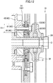
- FIG. 12 exemplifies a configuration of the cut-off machine 10 according to the first embodiment.
- the movable base 51 is formed such that the inner peripheral edge of the movable guard 50 (movable base 51) is located closer to the rotary shaft 20 than the coupling bolts 63 are.
- This configuration makes it possible to increase a length X1 of a receiving surface for the movable guard 50 (i.e., a length in the radial direction of a portion serving as the receiving surface for the movable guard 50) by radially outwardly expanding the portion serving as the receiving surface for the movable guard 50.
- the portion serving as the receiving surface for the movable guard 50 corresponds to a portion of the first coupling member 61 and a portion of the second coupling member 62, the portions overlapping with the movable base 51 in the axial direction of the rotary shaft 20.
- the configuration in which the movable base 51 is formed such that the inner peripheral edge of the movable guard 50 (movable base 51) is located closer to the rotary shaft 20 than the coupling bolts 63 are, makes it possible to radially inwardly expand the portion serving as the receiving surface for the movable guard 50 (in this example, the portions of the first and second coupling members 61 and 62, which overlap with the movable base 51 in the axial direction of the rotary shaft 20) to a greater extent than in a case where the inner peripheral edge of the movable guard 50 is located remoter from the rotary shaft 20 than the coupling bolts 63 are.
- the length X1 of the receiving surface for the movable guard 50 can be increased so as not to expand the portion serving as the receiving surface for the movable guard 50 (in particular, a portion which faces a cutting target when the blade cuts the cutting target; in this example, a front portion of the first coupling member 61 and a front portion of the second coupling member 62) outward in the radial direction (or so as to reduce the outward expansion in the radial direction).
- This feature makes it possible to increase the length X1 of the receiving surface for the movable guard 50 while reducing a decrease in the maximum cutting depth of the blade.
- Increasing the length X1 of the receiving surface for the movable guard 50 in this manner makes it possible to reduce deformation (deformation in the axial direction) of the movable guard 50 which may be caused by an external force, thereby enabling enhancement of the durability of the movable guard 50.
- the coupling bolts 63 are disposed closer to the rotary shaft 20 than the outer peripheral edges of the pair of holding members 31 and 32 are.
- This configuration allows the inner peripheral edge of the movable guards (movable base 51) to be positioned further closer to the rotary shaft 20 than in a case where the coupling bolts 63 are located remoter from the rotary shaft 20 than the outer peripheral edges of the pair of holding members 31 and 32 are.
- the length X1 of the receiving surface for the movable guard 50 can be further increased.
- the configuration in which the second coupling member 62 is provided with the protrusions 62b and the second insertion holes 602 are formed in the protrusions 62b, allows the coupling bolts 63 inserted in the second insertion holes 602 to be supported on the protrusions 62b.
- this configuration allows the protrusions 62b to function as fastening bearing surfaces for the coupling bolts 63.
- the coupling bolts 63 can be fastened easy.
- each of the protrusions 62b of the second coupling member 62 a portion located radially outside the associated second insertion hole 602 and a portion located radially inside the associated second insertion hole 602 are cut out.
- This configuration allows a decrease in the length in the radial direction of each of the protrusions 62b of the second coupling member 62.
- the second coupling member 62 in this example, the second annular part 62a
- such a decrease in the length in the radial direction of each protrusion 62b allows a decrease in the length in the radial direction of each slot 501 (in which the protrusion 62b is disposed) of the movable base 51.
- the movable base 51 can be reduced in size.
- a space in which the sealing members (in this example, the first and second sealing member 65 and 66) are provided can be ensured while a decrease in the maximum cutting depth of the blade 21 is reduced.
- first, second, and third sealing members 65, 66, and 67 makes it possible to reduce entry of dust particles into the coupling mechanism 60. As a result, deterioration in sliding of the movable base 51 which may be caused by the entry of dust particle into the coupling mechanism 60 can be prevented or reduced.
- the grease grooves 68 allow the movable base 51 to slide smoothly.
- first movable-guard part 55 and the second movable-guard part 56 are moved complementarily to each other, thereby allowing the predetermined angle range (in this example, the range of 180° or more) of the outer periphery of the blade 21 to be covered constantly.
- FIG. 13 exemplifies a configuration of a cut-off machine 10 according to a second embodiment, which is not according to the invention.
- the cut-off machine 10 according to the second embodiment is different from the cut-off machine 10 according to the first embodiment in configurations of a movable base 51 and a coupling mechanism 60.
- no slot 501 is formed in the movable base 51.
- the coupling mechanism 60 is configured as described below.
- the coupling mechanism 60 includes a first coupling member 61, a second coupling member 62, and a plurality of (in this example, four) coupling bolts 63.
- the first coupling member 61 is disposed between a fixed support 41 and the movable base 51.
- the first coupling member 61 has a first annular part 61a and a first cylindrical part 61b.
- the first annular part 61a has an annular shape and is disposed between the fixed support 41 and the movable base 51.
- a length between the outer peripheral edge of the first annular part 61a (first coupling member 61) and a shaft center O of a rotary shaft 20 in a radial direction is equal to or shorter than a length between outer peripheral edges of first and second holding members 31 and 32 (precisely speaking, one of the outer peripheral edges of the first and second holding members 31 and 32, which is remoter from the shaft center O) and the shaft center O of the rotary shaft 20 in the radial direction.
- the first cylindrical part 61b has a cylindrical shape, and is provided on an inner peripheral edge portion of the first annular part 61a.
- the first cylindrical part 61b projects from the first annular part 61a into an inside of an inner peripheral edge of the movable base 51 (in this example, into an opening 500). Note that in this example, the first cylindrical part 61b is formed integrally with the first annular part 61a.
- the first coupling member 61 is provided with a plurality of (in this example, four) first insertion holes 601 which respectively correspond to the plurality of coupling bolts 63.
- the plurality of first insertion holes 601 pass through the first coupling member 61 (in this example, the first annular part 61a) in the axial direction.
- the four first insertion holes 601 are arranged at 90-degree intervals in a circumferential direction.
- the second coupling member 62 is disposed between the movable base 51 and the pair of holding members (in this example, the first holding member 31).
- the movable base 51 is slidably clamped between the second coupling member 62 and the first coupling member 61.
- the second coupling member 62 has a second annular part 62a and a second cylindrical part 62d.
- the second annular part 62a is in an annular shape and is disposed between the movable base 51 and the pair of holding members (in this example, the first holding member 31).
- a length between the outer peripheral edge of the second annular part 62a (second coupling member 62) and the shaft center O of the rotary shaft 20 in the radial direction is equal to or shorter than a length between the outer peripheral edges of the first and second holding members 31 and 32 (precisely speaking, one of the outer peripheral edges of the first and second holding members 31 and 32, which is remoter from the shaft center O) and the shaft center O of the rotary shaft 20 in the radial direction.
- the second annular part 62a and the first annular part 61a face each other with the movable base 51 interposed therebetween.
- the second cylindrical part 62d has a cylindrical shape, is provided on an inner peripheral edge portion of the second annular part 62a, and projects from the second annular part 62a into the inner peripheral edge of the movable base 51 (in this example, into the opening 500). Note that in this example, the second cylindrical part 62d is formed integrally with the second annular part 62a.
- the plurality of (in this example, four) coupling bolts 63 fix the first coupling member 61 to the fixed support 41.
- the plurality of coupling bolts 63 are inserted into the first insertion holes 601, respectively and are screwed into the fixed support 41.
- the fixed support 41 is provided with a plurality of (in this example, four) coupling bolt holes 43 which respectively correspond to the plurality of coupling bolts 63.
- the four coupling bolts 63 are screwed into the four coupling bolt holes 43, respectively.
- the inner peripheral surface of one of the first cylindrical part 61b and the second cylindrical part 62d is formed in a female-screw shape, and the outer peripheral surface of the other is formed in a male-screw shape corresponding to the female-screw shape.
- One of the first cylindrical part 61b and the second cylindrical part 62d is screwed into the other.
- the inner peripheral surface of the second cylindrical part 62d is formed in the female-screw shape
- the outer peripheral surface of the first cylindrical part 61b is formed in the male-screw shape.
- the first cylindrical part 61b is screwed into the second cylindrical part 62d.
- one (i.e., the cylindrical part whose inner peripheral surface is formed in the female-screw shape) of the of the first cylindrical part 61b and the second cylindrical part 62d receives the other (i.e., the other cylindrical part whose inner peripheral surface is formed in the male-screw shape) screwed therein, thereby allowing the movable base 51 to be slidably clamped between the first coupling member 61 and the second coupling member 62.
- each of the plurality of coupling bolts 63 is located closer to the rotary shaft 20 than the outer peripheral edges of the first and second holding members 31 and 32 (precisely speaking, one of the outer peripheral edges of the first and second holding members 31 and 32, which is remoter from the shaft center O) are.
- the plurality of coupling bolts 63 is located at a position close to the shaft center O of the rotary shaft 20.
- the inner peripheral edge of the movable base 51 (in this example, the inner peripheral edge of the opening 500) is located closer to the rotary shaft 20 than the plurality of coupling bolts 63 is.
- the second embodiment includes a third sealing member 67 having a ring shape.
- a third ring groove 607 into which the third sealing member 67 is fitted is provided in an outer peripheral surface of a base end portion of the first cylindrical part 61b (a portion of an outer peripheral surface facing a distal end portion of the second cylindrical part 62d). With this configuration, a space between the first cylindrical part 61b and the second cylindrical part 62d is sealed.
- the cut-off machine 10 according to the second embodiment has the same configuration as that of the cut-off machine 10 according to the first embodiment.
- the cut-off machine 10 according to the second embodiment provides the same or similar effects as those provided by the cut-off machine 10 according to the first embodiment.
- a length X1 of a receiving surface for the movable guard 50 (a length in the radial direction of a portion serving as the receiving surface for the movable guard 50) can be increased so as not to expand the portion serving as the receiving surface for the movable guard 50 (in particular, a portion which faces a cutting target when the blade 21 cuts the cutting target; in this example, a front portion of the first coupling member 61 and a front portion of the second coupling member 62) outward in the radial direction (or so as to reduce the outward expansion in the radial direction).
- This feature makes it possible to increase the length X1 of the receiving surface for the movable guard 50 while reducing a decrease in a maximum cutting depth of the blade.
- the case where the surface of the first coupling member 61, which faces the movable base 51, is provide with the grease grooves 68 has been described as an example.
- a surface of the second coupling member 62, which faces the movable base 51 may be provided with the grease grooves 68.
- at least one of the surface of the first coupling member 61 that faces the movable base 51 or the surface of the second coupling member 62 that faces the movable base 51 may be provided with the grease grooves 68.
- the present disclosure is useful as a cut-off machine.
Landscapes
- Engineering & Computer Science (AREA)
- Mechanical Engineering (AREA)
- Life Sciences & Earth Sciences (AREA)
- Wood Science & Technology (AREA)
- Forests & Forestry (AREA)
- Processing Of Stones Or Stones Resemblance Materials (AREA)
- Sawing (AREA)
Description
- The present disclosure relates to a cut-off machine according to the preamble of claim 1. Such a cut-off machine is disclosed in
US 4 774 866 A . - Conventionally, there has been known a cut-off machine which includes a circular blade and is configured to cut a cutting target (for example, a concrete body) by rotationally driving the circular blade. For example, Japanese Examined Patent Publication No.
H07-14570 - In the cut-off machine as in Japanese Examined Patent Publication No.
H07-14570 - In the cut-off machine as described above, if an external force acts on the movable guard to deform the movable guard in an axial direction, it becomes difficult to smoothly turn the movable guard. In order to reduce or prevent this deformation of the movable guard, it is conceivable to radially outwardly expanding a portion located adjacent to the rotary shaft and serving as a receiving surface for the movable guard (i.e., a portion receiving the movable guard in the radial direction) so as to increase a length of the portion serving as the receiving surface for the movable guard (i.e., a length in a radial direction of the portion serving as the receiving surface for the movable guard). However, when the portion serving as the receiving surface for the movable guard (in particular, a portion which faces a cutting target when the blade cuts the cutting target) is radially outwardly expanded beyond the outer peripheral edges of the pair of holding members, a maximum cutting depth of the blade becomes shallow.
- As can be seen, in the above-described cut-off machine, it is difficult to increase the length of the receiving surface for the movable guard while reducing a decrease in the maximum cutting depth of the blade.
- The present invention provides a cut-off machine according to claim 1. This cut-off machine includes: a rotary shaft; a blade having a circular shape, and having, in a central portion thereof, an insertion hole in which the rotary shaft is inserted; a holding mechanism configured to hold the blade with respect to the rotary shaft, and including a pair of holding members which each has an annular shape and which clamp the blade therebetween; a fixed guard configured to cover a portion of an outer periphery of the blade, and including a fixed support which is provided with a bearing portion rotatably supporting the rotary shaft; a movable guard configured to movably cover a portion of the outer periphery of the blade, the portion being circumferentially adjacent to the portion covered with the fixed guard, the movable guard having a movable base formed to surround a periphery of the rotary shaft; and a coupling mechanism configured to couple the movable guard to the fixed guard such that the movable guard can be turned around the rotary shaft, and including a first coupling member, a second coupling member, and a coupling bolt, the first coupling member being disposed between the fixed support and the movable base, the second coupling member being disposed between the movable base and the pair of holding members, the first coupling member and the second coupling member slidably clamping the movable base therebetween, the coupling bolt fixing the first coupling member to the fixed support. An inner peripheral edge of the movable base is located closer to the rotary shaft than the coupling bolt is.
- According to the present invention, the movable base is formed such that the inner peripheral edge of the movable base is located closer to the rotary shaft than the coupling bolt is. This configuration makes it possible to expand, radially inwardly (i.e., toward the shaft center of the rotary shaft), the portion serving as the receiving surface for the movable guard to a greater extent than in a case where the inner peripheral edge of a movable guard is located remoter from the rotary shaft than the coupling bolt is. Thus, a length of the receiving surface for the movable guard (a length in the radial direction of the portion serving as the receiving surface for the movable guard) can be increased so as not to expand the portion serving as the receiving surface for the movable guard (in particular, a portion which faces a cutting target when the blade cuts the cutting target) outward in the radial direction (or so as to reduce the outward expansion in the radial direction). This feature makes it possible to increase the length of the receiving surface for the movable guard while reducing a decrease in a maximum cutting depth of the blade.
-
-
FIG. 1 is a side view exemplifying an external appearance of a cut-off machine according to a first embodiment; -
FIG. 2 is a perspective view exemplifying the external appearance of the cut-off machine according to the first embodiment; -
FIG. 3 is a perspective view exemplifying the external appearance of the cut-off machine according to the first embodiment; -
FIG. 4 is a side view exemplifying a configuration of the cut-off machine according to the first embodiment; -
FIG. 5 is a side view exemplifying a configuration of a main part of the cut-off machine according to the first embodiment; -
FIG. 6 is a cross-sectional view exemplifying the configuration of the cut-off machine according to the first embodiment; -
FIG. 7 is an exploded perspective view exemplifying the configuration of the main part of the cut-off machine according to the first embodiment; -
FIG. 8 is an exploded perspective view exemplifying the configuration of the main part of the cut-off machine according to the first embodiment; -
FIG. 9 is a side view exemplifying the configuration of the main part of the cut-off machine according to the first embodiment; -
FIG. 10 is a side view exemplifying an operation of the cut-off machine according to the first embodiment; -
FIG. 11 is a cross-sectional view illustrating a configuration of a cut-off machine of a comparative example; -
FIG. 12 is a cross-sectional view for illustrating a length of a receiving surface for a movable guard of the first embodiment; and -
FIG. 13 is a cross-sectional view exemplifying a configuration of a cut-off machine according to a second embodiment, which is not according to the invention. - Embodiments will be described below in detail with reference to the accompanying drawings. In the drawings, like reference characters are used to denote identical or equivalent components, and description thereof will not be repeated herein.
- Each of
FIGS. 1 to 3 exemplifies an external appearance of a cut-offmachine 10 according to a first embodiment. The cut-offmachine 10 includes a circular blade which can be rotationally driven by a drive source such as an engine, and is configured to cut a cutting target (for example, a concrete body) with the circular blade that is being rotationally driven. In this example, the cut-offmachine 10 is embodied as a handheld cut-off machine (the so-called engine cut-off machine), and configured such that a worker operates the cut-offmachine 10 while holding the cut-offmachine 10 with both hands. Specifically, the cut-offmachine 10 includes arotary shaft 20, ablade 21, aholding mechanism 30, afixed guard 40, amovable guard 50, acoupling mechanism 60, ahousing 11, adust collecting mechanism 12, afirst handle 13, asecond handle 14, and aleg 15. - Note that in the following description, for the sake of convenience of the description, a posture in which the cut-off
machine 10 is placed on the ground (a horizontal surface) is defined as the reference posture of the cut-offmachine 10, and directions relating to the cut-offmachine 10 are defined based on a case where the cut-offmachine 10 placed on the ground is viewed from theblade 21. In other words, directions (upper, lower, right, left, front, and rear directions) as used in the following description represents directions in a state where the cut-offmachine 10 placed on the ground is viewed from theblade 21. For example, inFIG. 1 , the right-to-left direction on a plane of paper corresponds to the front-to-rear direction, a side on the plane of paper facing the viewer corresponds to the right side, and a side on the plane of paper facing away from the viewer corresponds to the left side. - The
rotary shaft 20 is configured to be rotationally driven by power of the later-described drive source (not shown). Therotary shaft 20 is rotatably supported on thefixed guard 40. In this example, therotary shaft 20 is supported such that a shaft center O extends in the right-to-left direction. - The
blade 21 has a circular shape. Theblade 21 has, in a central portion thereof, aninsertion hole 201 into which therotary shaft 20 is inserted. In this example, theblade 21 is comprised of a diamond blade. - Note that in the following description, for the sake of convenience of the description, a counterclockwise direction in
FIG. 1 is denoted as a normal rotation direction of the blade 21 (for example, a direction in which theblade 21 rotates to cut a cutting target), and a direction reverse to the normal rotation direction (a clockwise direction inFIG. 1 ) is denoted as a reverse rotation direction. - The
holding mechanism 30 is configured to hold theblade 21 with respect to therotary shaft 20. In this example, theholding mechanism 30 holds theblade 21 with respect to therotary shaft 20 in a detachable manner. With this configuration, when therotary shaft 20 is rotationally driven, theblade 21 held with respect to therotary shaft 20 via theholding mechanism 30 is rotationally driven together with therotary shaft 20. Note that a configuration of theholding mechanism 30 will be described later in detail. - The
fixed guard 40 is configured to cover a portion of an outer periphery of theblade 21. Themovable guard 50 is configured to movably cover another portion, of the outer periphery of theblade 21, which is circumferentially adjacent to the portion covered with thefixed guard 40. Thecoupling mechanism 60 is configured to couple themovable guard 50 to thefixed guard 40 such that themovable guard 50 can be turned around therotary shaft 20. In this example, the fixedguard 40 covers a rear side of theblade 21, and themovable guard 50 covers an upper portion and a lower portion of theblade 21, whereas a front portion of theblade 21 is exposed. Note that configurations of the fixedguard 40, themovable guard 50, and thecoupling mechanism 60 will be described later in detail. - The
housing 11 houses the drive source (not shown) such as the engine. Thehousing 11 and the fixedguard 40 are coupled to each other. At the coupling portion between thehousing 11 and the fixedguard 40, a power transmission mechanism (for example, a combination of gears, pulleys, belts, and the like; not shown) is provided which transmits the power of the drive source to therotary shaft 20 and thedust collecting mechanism 12. With this configuration, when the drive source housed in thehousing 11 is actuated, the power of the drive source is transmitted via the power transmission mechanism to therotary shaft 20 and thedust collecting mechanism 12, and thus, therotary shaft 20 is rotationally driven and thedust collecting mechanism 12 operates. - The
dust collecting mechanism 12 is configured to collect and accumulate dust particles generated in cutting a cutting target (for example, a concrete body or the like). Specifically, thedust collecting mechanism 12 includes adust collecting fan 12a and adust collecting hose 12b. A suction inlet of thedust collecting fan 12a communicates with an inside of the fixedguard 40, and a blowout outlet of thedust collecting fan 12a communicates with one end of thedust collecting hose 12b. Thedust collecting fan 12a is configured to be driven by the power of the drive source (not shown) housed in thehousing 11 so as to suck air from the inside of the fixedguard 40 through the suction inlet and blow out the sucked air to thedust collecting hose 12b through the blowout outlet. One end of thedust collecting hose 12b is connected to the blowout outlet of thedust collecting fan 12a, and the other end of thedust collecting hose 12b is connected to a dust collecting bag (that is, a bag for collecting and accumulating the dust particles; not shown). With this configuration, the dust particles generated in cutting the cutting target sequentially passes through the fixedguard 40, thedust collecting fan 12a, and thedust collecting hose 12b so as to be collected and accumulated in the dust collecting bag. - The
first handle 13 extends from an upper left portion of the fixedguard 40, passes above a rear portion of the fixedhandle 40, and reaches a lower right portion of the fixedguard 40. Thesecond handle 14 is provided on a rear portion of thehousing 11. Theleg 15 is provided on a lower portion of the fixedguard 40. - Configurations of respective components of the cut-off
machine 10 according to the first embodiment will be described blow with reference toFIGS. 1 to 9 . Note thatFIG. 4 is a side view illustrating the cut-offmachine 10 with theblade 21 detached (i.e., a plan view viewed from a later-described second fixed-guard part 46).FIG. 5 is a side view illustrating, on an enlarged scale, a configuration of thecoupling mechanism 60 and the vicinity thereof (i.e., a plan view viewed from the later-described second fixed-guard part 46).FIG. 6 is a cross-sectional view taken along line A-O-B inFIG. 5 . Each ofFIGS. 7 and8 is an exploded perspective view of the configuration of thecoupling mechanism 60 and the vicinity thereof.FIG. 9 is a side view illustrating a configuration of a later-describedmovable base 51, asecond coupling member 62, and coupling bolts 63 (i.e., a plan view viewed from the later-described second fixed-guard part 46). - The holding
mechanism 30 is configured to hold theblade 21 with respect to therotary shaft 20. Specifically, the holdingmechanism 30 includes a pair of holding members (first and second holdingmembers 31 and 32), a fixingmember 33, awasher 34, and a mountingbolt 35. - Each of the first and second holding
members members blade 21 therebetween. In this example, the first holdingmember 31 is disposed on a side of theblade 21, which is adjacent to the coupling mechanism 60 (specifically, on the left side), and the second holdingmember 32 is disposed on a side of theblade 21, which is remote from the coupling mechanism 60 (specifically, on the right side). - The fixing
member 33 has an annular shape, and is fixed while therotary shaft 20 passes through the fixingmember 33. Thewasher 34 has an annular shape. The pair of holding members (first and second holdingmembers 31 and 32) is sandwiched between thewasher 34 and the fixingmember 33. In this example, the first holdingmember 31 is disposed between the fixingmember 33 and theblade 21, and the second holdingmember 32 is disposed between theblade 21 and thewasher 34 - The mounting
bolt 35 is inserted into thewasher 34 and is screwed into therotary shaft 20. With this configuration, screwing the mountingbolt 35 into therotary shaft 20 causes the first and second holdingmembers member 33 and thewasher 34, and theblade 21 to be clamped tightly by the first and second holdingmembers rotary shaft 20 can be held with respect to theblade 21. On the other hand, loosening the mountingbolt 35 screwed into therotary shaft 20 reduces the tightness with which the first and second holdingmembers member 33 and thewasher 34, and the tightness with which theblade 21 is clamped by the first and second holdingmembers blade 21 can be detached from therotary shaft 20. - In this example, a holding
ring 36 having an annular shape is provided between an outer peripheral surface of therotary shaft 20 and an inner peripheral surface of theinsertion hole 201 of theblade 21. Specifically, therotary shaft 20 is fitted into the holdingring 36, and the holdingring 36 is fitted into theinsertion hole 201 of theblade 21. - The fixed
guard 40 is configured to cover a portion of the outer periphery of the blade 21 (in this example, a rear portion of the blade 21). In this example, the fixedguard 40 includes a fixedsupport 41, a first fixed-guard part 45, and a second fixed-guard part 46. In addition, in this example, the fixedguard 40 is made of a light alloy such as an aluminum alloy. - The fixed
support 41 has a bearingportion 42. The bearingportion 42 is configured to rotatably support therotary shaft 20. In this example, the fixedsupport 41 is disposed adjacent to an end surface (left side) of theblade 21. The fixedsupport 41 has a cylindrical shape, and the bearingportion 42 is disposed in a central portion of the fixedsupport 41. The fixingmember 33, the first holdingmember 31, theblade 21, the second holdingmember 32, and thewasher 34 are arranged sequentially in a direction from the bearingportion 42 of the fixedsupport 41 toward the mountingbolt 35. - The first fixed-
guard part 45 extends from the fixedsupport 41 outward in a radial direction so as to cover a portion of theblade 21. In this example, the first fixed-guard part 45 is disposed adjacent to one end surface (left side) of theblade 21. The first fixed-guard part 45 has a fan shape of which the center corresponds to therotary shaft 20, and the outer peripheral edge thereof is located outside in a radial direction with respect to the outer peripheral edge of the blade 21 (i.e., located further remote from the shaft center O of the rotary shaft 20). Note that in this example, the fixedsupport 41 and the first fixed-guard part 45 are formed integrally with each other. - The second fixed-
guard part 46 is disposed so as to face the first fixed-guard part 45 in the axial direction of therotary shaft 20, has an outer peripheral edge coupled to the outer peripheral edge of the first fixed-guard part 45. In this example, the second fixed-guard part 46 is disposed adjacent to the other end surface (the right side) of theblade 21. The second fixed-guard part 46 has an arc shape so as to extend along the outer peripheral edge of the first fixed-guard part 45 around therotary shaft 20. - The first fixed-
guard part 45 is provided with acoupling portion 47. Thecoupling part 47 is coupled to thehousing 11, and houses therein part of the above-described power transmission mechanism (that transmits the power of the drive source housed in thehousing 11 to therotary shaft 20 supported on the bearingportion 42 and the dust collecting mechanism 12). - A reinforcing
part 48 is provided on a circumferential end portion of the fixed guard 40 (specifically, an upstream end portion in the normal rotation direction). Note that it is preferable that the reinforcingpart 48 is made of a material (for example, iron) which is stronger than the material (for example, a light alloy) forming the fixedguard 40. - The
movable guard 50 is configured to movably cover portions of the outer periphery of theblade 21, which are each adjacent to the portion covered with the fixedguard 40 in the circumferential direction of the blade 21 (in this example, an upper portion and a lower portion of the blade 21). In this example, themovable guard 50 includes amovable base 51, a first movable-guard part 55, and a second movable-guard part 56. In this example, the first movable-guard part 55 and the second movable-guard part 56 are each made of a light alloy such as an aluminum alloy. Themovable base 51 is made of a material (for example, iron) which is stronger than the material forming each of the first movable-guard part 55 and the second movable-guard part 56. - The
movable base 51 is shaped so as to surround the periphery of therotary shaft 20. In this example, themovable base 51 has a plate shape having anopening 500 formed in a central portion thereof. The opening 500 passes through themovable base 51 in an axial direction and has a circular shape surrounding the entire periphery of therotary shaft 20. Therotary shaft 20 and the fixingmember 33 are disposed in theopening 500. In other words, themovable base 51 is formed so as to surround the periphery of the fixingmember 33. - In this example, the
movable base 51 is provided with a plurality of (specifically, four)slots 501. The plurality ofslots 501 pass through themovable base 51 in the axial direction. Eachslot 501 has an arc shape extending along the circumferential direction of therotary shaft 20. In this example, the fourslots 501 are arranged at 90-degree intervals in the circumferential direction. - The first movable-
guard part 55 extends from themovable base 51 toward one circumferential end portion of the fixedguard 40, and is configured to movably cover a portion of the outer periphery of theblade 21, the portion being adjacent to one circumferential end of the portion covered with the fixed guard 40 (in this example, an upper portion of the blade 21). Specifically, the first movable-guard part 55 is in a plate shape, and has a distal end portion bended in a U-shape so as to cover the portion of the outer periphery of the blade 21 (in this example, the upper portion of the blade 21). In addition, the first movable-guard part 55 is retractable in the fixedguard 40. - The second movable-
guard part 56 extends from themovable base 51 toward the other circumferential end portion of the fixedguard 40, and is configured to movably cover a portion of the outer periphery of theblade 21, the portion being adjacent to the other circumferential end of the portion covered with the fixed guard 40 (in this example, a lower portion of the blade 21). Specifically, the second movable-guard part 56 is in a plate shape, and has a distal end portion bended in a U-shape so as to cover the portion of the outer periphery of the blade 21 (in this example, the lower portion of the blade 21). In addition, the second movable-guard part 56 is retractable in the fixedguard 40. - With this configuration, when the
movable base 51 is turned around therotary shaft 20, one of the first movable-guard part 55 and the second movable-guard part 56 moves in a direction so as to enter the inside of the fixedguard 40, and at the same time, the other moves in a direction so as to come out of the fixedguard 40. - In addition, the first movable-
guard part 55 is provided with afirst recess 55a into which a portion of the movable base 51 (in this example, an upper end portion) is fitted. The first movable-guard part 55 is fixed with a plurality of (in this example, four) first fixingbolts 515 to a portion of the movable base 51 (the portion fitted into thefirst recess 55a). Specifically, this portion of the movable base 51 (the portion fitted into thefirst recess 55a) is provided with a plurality of (in this example, four) first fixingbolt holes 505, and thefirst recess 55a is provided with a plurality of (in this example, four) first communicating holes (not shown) which respectively communicate with the plurality of first fixing bolt holes 505. The first fixingbolts 515 are inserted into the first communicating holes of the first movable-guard part 55, and are screwed into the firstfixing bolt holes 505 of themovable base 51. - The second movable-
guard part 56 is provided with asecond recess 56a into which a portion of the movable base 51 (in this example, a lower end portion) is fitted. The second movable-guard part 56 is fixed with a plurality of (in this example, four) second fixingbolts 516 to the portion of the movable base 51 (a portion fitted into thesecond recess 56a). Specifically, this portion of the movable base 51 (the portion fitted into thesecond recess 56a) is provided with a plurality of (in this example, four) secondfixing bolt holes 506, and thesecond recess 56a is provided with a plurality of (in this example, four) second communicating holes (not shown) which respectively communicate with the plurality of second fixing bolt holes 506. The second fixingbolts 516 are inserted into the second communicating holes of the second movable-guard part 56, and are screwed into the secondfixing bolt holes 506 of themovable base 51. - The
coupling mechanism 60 is configured to couple themovable guard 50 to the fixedguard 40 such that themovable guard 50 can be turned around therotary shaft 20. Specifically, thecoupling mechanism 60 includes afirst coupling member 61, thesecond coupling member 62, and the plurality of (in this example, four)coupling bolts 63. - The
first coupling member 61 is disposed between the fixedsupport 41 and themovable base 51. In this example, thefirst coupling member 61 has a firstannular part 61a and a firstcylindrical part 61b. - The first
annular part 61a is in an annular shape and is disposed between the fixedsupport 41 and themovable base 51. In this example, a length between the outer peripheral edge of the firstannular part 61a (the first coupling member 61) and the shaft center O of therotary shaft 20 in a radial direction is equal to or shorter than a length between outer peripheral edges of the first and second holdingmembers 31 and 32 (precisely speaking, one of the outer peripheral edges of the first and second holdingmembers rotary shaft 20 in the radial direction. - The first
cylindrical part 61b is in a cylindrical shape, and provided on an inner peripheral edge portion of the firstannular part 61a. The firstcylindrical part 61b projects from the firstannular part 61a into an inside of an inner peripheral edge of the movable base 51 (in this example, into the opening 500). In this example, the firstcylindrical part 61b is slidably fitted into the inner peripheral edge (specifically, the opening 500) of themovable base 51, and the inner peripheral surface of the firstcylindrical part 61b faces the outer peripheral surface of the fixingmember 33. Note that in this example, the firstcylindrical part 61b is formed integrally with the firstannular part 61a. - The
first coupling member 61 is provided with a plurality of (in this example, four) first insertion holes 601 which respectively correspond to the plurality ofslots 501 of themovable base 51. The plurality of first insertion holes 601 pass through the first coupling member 61 (in this example, the firstannular part 61a) in the axial direction and respectively communicate with the plurality ofslots 501. In this example, the four first insertion holes 601 are arranged at 90-degree intervals in the circumferential direction. - The
second coupling member 62 is disposed between themovable base 51 and the pair of holding members (in this example, the first holding member 31). Themovable base 51 is slidably clamped between thesecond coupling member 62 and thefirst coupling member 61. In this example, thesecond coupling member 62 has a secondannular part 62a. - The second
annular part 62a is in an annular shape and is disposed between themovable base 51 and the pair of holding members (in this example, the first holding member 31). In this example, a length between the outer peripheral edge of the secondannular part 62a (second coupling member 62) and the shaft center O of therotary shaft 20 in a radial direction is equal to or shorter than a length between the outer peripheral edges of the first and second holdingmembers 31 and 32 (precisely speaking, one of the outer peripheral edges of the first and second holdingmembers rotary shaft 20 in the radial direction. In addition, the secondannular part 62a and the firstannular part 61a face each other with themovable base 51 interposed therebetween. Further, the firstcylindrical part 61b is fitted into the secondannular part 62a. - In this example, the
second coupling member 62 has a plurality of (in this example, four)protrusions 62b which respectively correspond to the plurality ofslots 501 of themovable base 51. The plurality ofprotrusions 62b respectively protrude into the plurality ofslots 501. In this example, each of theprotrusions 62b has an arc shape extending along theslot 501 and protrudes from the secondannular part 62a into theslot 501. The fourprotrusions 62b are arranged at 90-degree intervals in the circumferential direction. Note that in this example, the plurality ofprotrusions 62b are formed integrally with the secondannular part 62a. - In this example, in each
protrusion 62b, a portion located radially outside asecond insertion hole 602 and a portion located radially inside the associatedsecond insertion hole 602 are cut out. In other words, each of theprotrusions 62b is comprised of two projections which are disposed on both circumferential sides of thesecond insertion hole 602. Eachprotrusion 62b has a length, in the radial direction, which allows theprotrusion 62b to function as a fastening bearing surface for the associated coupling bolt 63 (for example, a length which is equivalent to a diameter of the coupling bolt 63). In addition, the length of eachprotrusion 62b in the radial direction is set to be shorter than a length of eachslot 501 in the radial direction. For example, if the outer diameter (nominal diameter) of a threaded portion of eachcoupling bolt 63 is 4 mm, the length of eachprotrusion 62b in the radial direction is set to be approximately 4 mm and the length of eachslot 501 in the radial direction is set to be approximately 5 mm. Note that the length of eachprotrusion 62b in the radial direction may be longer than, or shorter than, the outer diameter of the threaded portion of eachcoupling bolt 63. Alternatively, the length of the threaded portion of eachcoupling bolt 63 may be the same as the outer diameter of the threaded portion of eachcoupling bolt 63. - The
second coupling member 62 is provided with the plurality of (in this example, four) the second insertion holes 602 which respectively correspond to the plurality ofslots 501. Each of the plurality of second insertion holes 602 passes through the second coupling member 62 (in this example, the secondannular part 62a) in the axial direction and is configured to communicate with an associated one of the plurality ofslots 501. In this example, the four second insertion holes 602 are arranged at 90-degree intervals in the circumferential direction. - In this example, each of the plurality of second insertion holes 602 is formed in an associated one of the plurality of
protrusions 62b. Specifically, eachsecond insertion hole 602 is formed in a central portion of the associatedprotrusion 62b in plan view. In other words, in plan view, on the both circumferential sides of eachsecond insertion hole 602, theprotrusion 62b is provided. With this configuration, thecoupling bolts 63 inserted into the second insertion holes 602 are supported on theprotrusions 62b. - The plurality of (in this example, four)
coupling bolts 63 fix the first coupling member 61 (in this example, thefirst coupling member 61 and the second coupling member 62) to the fixedsupport 41. The plurality ofcoupling bolts 63 are sequentially inserted into the second insertion holes 602, theslots 501, and the first insertion holes 601 and are screwed into the fixedsupport 41. Note that the fixedsupport 41 is provided with a plurality of (in this example, four) coupling bolt holes 43 which respectively correspond to the plurality ofcoupling bolts 63. The fourcoupling bolts 63 are screwed into the four coupling bolt holes 43, respectively. - As described above, the
coupling bolts 63, which are sequentially inserted into the second insertion holes 602 of thesecond coupling member 62, theslots 501 of themovable base 51, and the first insertion holes 601 of thefirst coupling member 61, are screwed into the fixedsupport 41, thereby allowing themovable base 51 to be slidably clamped between thefirst coupling member 61 and thesecond coupling member 62. - In the cut-off
machine 10 according to the first embodiment, the plurality ofcoupling bolts 63 is located closer to therotary shaft 20 than the outer peripheral edges of the first and second holdingmembers 31 and 32 (precisely speaking, one of the outer peripheral edges of the first and second holdingmembers coupling bolts 63 is located at a position close to the shaft center O of therotary shaft 20. The inner peripheral edge of the movable base 51 (in this example, the inner peripheral edge of the opening 500) is located closer to therotary shaft 20 than the plurality ofcoupling bolts 63 is. - The cut-off
machine 10 includes a first sealingmember 65, asecond sealing member 66, and athird sealing member 67. In this example, each of the first, second, andthird sealing members - The
first sealing member 65 seals a space between thefirst coupling member 61 and themovable base 51. In this example, the first sealingmember 65 is in a ring shape. Afirst ring groove 605 into which the first sealingmember 65 is fitted is provided in an outer peripheral portion of a surface of the firstannular part 61a (in this example, a right end surface), which faces themovable base 51. With this configuration, the space between the firstannular part 61a and themovable base 51 is sealed. - The
second sealing member 66 seals a space between themovable base 51 and thesecond coupling member 62. In this example, the second sealingmember 66 is in a ring shape. Asecond ring groove 606 into which the second sealingmember 66 is fitted is provided in an outer peripheral portion of a surface of the secondannular part 62a (in this example, the left end surface), which faces themovable base 51. With this configuration, the space between the secondannular part 62a and themovable base 51 is sealed. - The
third sealing member 67 seals a space between thefirst coupling member 61 and thesecond coupling member 62. In this example, the third sealingmember 67 is in a ring shape. Athird ring groove 607 into which the third sealingmember 67 is fitted is provided in an outer peripheral surface of a distal end portion of the firstcylindrical part 61b (in a portion of the outer peripheral surface thereof, which faces the inner peripheral surface of the secondannular part 62a). With this configuration, the space between the firstcylindrical part 61b and the secondannular part 62a is sealed. - In addition, a plurality of (in this example, four)
grease grooves 68 are provided in a surface of the second coupling member 62 (specifically, the secondannular part 62a), which faces themovable base 51. Grease collects in thegrease grooves 68. In this example, each of thegrease grooves 68 is in an arc shape extending in the circumferential direction of therotary shaft 20. The fourgrease grooves 68 are arranged at 90-degree intervals in the circumferential direction. In other words, in this example, theprotrusions 62b and thegrease grooves 68 alternate each other in the circumferential direction. - The cut-off
machine 10 is further provided with abiasing mechanism 70. Thebiasing mechanism 70 is configured to bias themovable guard 50 in a predetermined rotation direction (in this example, the reverse rotation direction). Specifically, thebiasing mechanism 70 includes anelastic member 71, a first engagingpart 72, and a secondengaging part 73. Theelastic member 71 is comprised of, for example, an extension coil spring. The firstengaging part 72 is provided at the movable guard 50 (specifically, the movable base 51) and is engaged with one end of theelastic member 71. The secondengaging part 73 is provided at the fixed guard 40 (specifically, the first fixed-guard part 45) and is engaged with the other end of theelastic member 71. In this example, a hook is provided at each of the ends of theelastic member 71. The hook provided at the one end of theelastic member 71 is hooked to the first engagingpart 72, and the hook provided at the other end of theelastic member 71 is hooked to the second engagingpart 73. - The cut-off
machine 10 is provided with a stopper (not shown) which restricts the turn of themovable guard 50. In this example, the stopper is configured to restrict the turn of the movable guard 50 (specifically, turn in the reverse rotation direction) so as to prevent the first movable-guard part 55 from turning in the reverse rotation direction (in the clockwise direction inFIG. 4 ) beyond a predetermined position of turn. - Next, behavior of the
movable guard 50 will be described with reference toFIG. 10 . Note that inFIG. 10 , a first virtual line L1 is a virtual line which passes through one circumferential end portion (specifically, a downstream end portion in the normal rotation direction) of the first movable-guard part 55 and the shaft center O of therotary shaft 20 when the second movable-guard part 56 is retracted in the fixedguard 40 and the first movable-guard part 55 is positioned outside the fixed guard 40 (in other words, when the first movable-guard part 55 is in a fully-closed state and the second movable-guard part 56 is in a fully-opened state). A second virtual line L2 is a virtual line which passes through the one circumferential end portion of the first movable-guard part 55 and the shaft center O of therotary shaft 20 when the first movable-guard part 55 is retracted in the fixedguard 40 and the second movable-guard part 56 is positioned outside the fixed guard 40 (in other words, the first movable-guard part 55 is in a fully-opened state and the second movable-guard part 56 is in a fully-closed state). - When a user presses the second movable-
guard part 56 onto a cutting target in order to cut the cutting target with a lower portion of theblade 21, themovable guard 50 turns in the normal rotation direction (i.e., a counterclockwise direction inFIG. 10 ), against a biasing force (a force biasing themovable guard 50 in the reverse rotation direction) of thebiasing mechanism 70. Consequently, the second movable-guard part 56 moves in a direction so as to enter the inside of the fixedguard 40, and at the same time, the first movable-guard part 55 moves in a direction so as to come out of the fixedguard 40. As a result, the lower portion of theblade 21 is exposed while an upper portion of theblade 21 is covered with the first movable-guard part 55. - On the other hand, when the user stops pressing the second movable-
guard part 56 onto the cutting target, the biasing force of thebiasing mechanism 70 causes themovable guard 50 to turn in the reverse rotation direction (in a clockwise direction inFIG. 10 ). Consequently, the first movable-guard part 55 moves in a direction so as to enter the inside of the fixedguard 40, and at the same time, the second movable-guard part 56 moves in a direction so as to come out of the fixedguard 40. As a result, the upper portion of theblade 21 is exposed while the lower portion of theblade 21 is covered with the second movable-guard part 56. - As indicated by the first virtual line L1, when the second movable-
guard part 56 is retracted in the fixedguard 40 and the first movable-guard part 55 is positioned outside the fixed guard 40 (in other words, when the first movable-guard part 55 is in the fully-closed state and the second movable-guard part 56 is in the fully-opened state), the outer periphery of theblade 21 is covered with the first movable-guard part 55 and the fixedguard 40 in an angular range of 180° or more. As indicated by the second virtual line L2, when the first movable-guard part 55 is retracted in the fixedguard 40 and the second movable-guard part 56 is positioned outside the fixed guard 40 (in other words, the first movable-guard part 55 is in the fully-opened state and the second movable-guard part 56 is in the fully-closed state), the outer periphery of theblade 21 is covered with the second movable-guard part 56 and the fixedguard 40 in an angular range of 180° or more. As can be seen, the first movable-guard part 55 and the second movable-guard part 56 move complementarily, thereby maintaining a state in which a predetermined angle range of the outer periphery of the blade 21 (in this example, a range of 180° or more) is covered. In other words, the fixedguard 40 and themovable guard 50 are configured to constantly cover the predetermined angle range of the outer periphery of the blade 21 (in this example, the range of 180° or more). - Next, with reference to
FIGS. 11 and12 , the cut-offmachine 10 of the first embodiment and a cut-off machine of a comparative example (hereinafter, described as the "cut-offmachine 90") will be compared and described. -
FIG. 11 exemplifies a configuration of the cut-offmachine 90. The cut-offmachine 90 includes arotary shaft 91, a blade (not shown), a pair of holdingmembers guard 94, amovable guard 95, acoupling member 96, andcoupling bolts 97. The blade is clamped between the pair of holdingmembers rotary shaft 91. Therotary shaft 91 is rotatably supported on the fixedguard 94. Themovable guard 95 is slidably clamped between the fixedguard 94 and thecoupling member 96. Thecoupling member 96 is fixed to the fixedguard 94 with thecoupling bolts 97. With this configuration, themovable guard 95 can be turned around therotary shaft 91. - For the cut-off
machine 90 illustrated inFIG. 11 , if an external force acts on themovable guard 95 to deform themovable guard 95 in an axial direction, themovable guard 95 and the fixedguard 94 contact with each other, thereby increasing friction between themovable guard 95 and the fixedguard 94. As a result, it becomes difficult to smoothly turn themovable guard 95. Note that in the cut-offmachine 90 illustrated inFIG. 11 , an inner peripheral edge of themovable guard 95 is not located closer to therotary shaft 91 than thecoupling bolts 97 are (in other words, thecoupling bolts 97 are located closer to therotary shaft 91 than the inner peripheral edge of themovable guard 95 is). It is therefore difficult to radially inwardly expand a portion which serves as a receiving surface for themovable guard 95. Note that in the example illustrated inFIG. 11 , the portion serving as the receiving surface for themovable guard 95 corresponds to a portion of the fixedguard 94 and a portion of thecoupling member 96, the portions overlapping with themovable guard 95 in the axial direction of therotary shaft 91. Consequently, in the cut-offmachine 90 illustrated inFIG. 11 , in order to reduce the above-described deformation in themovable guard 95, it is conceivable to increase a length X9 of the portion serving as the receiving surface for the movable guard 95 (i.e., a length in the radial direction of the portion serving as the receiving surface for the movable guard 95). Such an increase in the length could be achieved by radially outwardly expanding the portion serving as the receiving surface for themovable guard 95. However, if the portion serving as the receiving surface for the movable guard 95 (in particular, a portion which faces a cutting target when the blade cuts the cutting target; in this example, a front portion) is radially outwardly expanded beyond the outer peripheral edges of the pair of holdingmembers machine 90 illustrated inFIG. 11 , it is difficult to increase the length X9 of the receiving surface for themovable guard 95 while reducing a decrease in the maximum cutting depth of the blade. -
FIG. 12 exemplifies a configuration of the cut-offmachine 10 according to the first embodiment. As illustrated inFIG. 12 , in the cut-offmachine 10, themovable base 51 is formed such that the inner peripheral edge of the movable guard 50 (movable base 51) is located closer to therotary shaft 20 than thecoupling bolts 63 are. This configuration makes it possible to increase a length X1 of a receiving surface for the movable guard 50 (i.e., a length in the radial direction of a portion serving as the receiving surface for the movable guard 50) by radially outwardly expanding the portion serving as the receiving surface for themovable guard 50. Note that in this example, the portion serving as the receiving surface for themovable guard 50 corresponds to a portion of thefirst coupling member 61 and a portion of thesecond coupling member 62, the portions overlapping with themovable base 51 in the axial direction of therotary shaft 20. - As described above, the configuration, in which the
movable base 51 is formed such that the inner peripheral edge of the movable guard 50 (movable base 51) is located closer to therotary shaft 20 than thecoupling bolts 63 are, makes it possible to radially inwardly expand the portion serving as the receiving surface for the movable guard 50 (in this example, the portions of the first andsecond coupling members movable base 51 in the axial direction of the rotary shaft 20) to a greater extent than in a case where the inner peripheral edge of themovable guard 50 is located remoter from therotary shaft 20 than thecoupling bolts 63 are. Thus, the length X1 of the receiving surface for themovable guard 50 can be increased so as not to expand the portion serving as the receiving surface for the movable guard 50 (in particular, a portion which faces a cutting target when the blade cuts the cutting target; in this example, a front portion of thefirst coupling member 61 and a front portion of the second coupling member 62) outward in the radial direction (or so as to reduce the outward expansion in the radial direction). This feature makes it possible to increase the length X1 of the receiving surface for themovable guard 50 while reducing a decrease in the maximum cutting depth of the blade. Increasing the length X1 of the receiving surface for themovable guard 50 in this manner makes it possible to reduce deformation (deformation in the axial direction) of themovable guard 50 which may be caused by an external force, thereby enabling enhancement of the durability of themovable guard 50. - Further, in this example, the
coupling bolts 63 are disposed closer to therotary shaft 20 than the outer peripheral edges of the pair of holdingmembers rotary shaft 20 than in a case where thecoupling bolts 63 are located remoter from therotary shaft 20 than the outer peripheral edges of the pair of holdingmembers movable guard 50 can be further increased. - In addition, the configuration, in which the
second coupling member 62 is provided with theprotrusions 62b and the second insertion holes 602 are formed in theprotrusions 62b, allows thecoupling bolts 63 inserted in the second insertion holes 602 to be supported on theprotrusions 62b. In other words, this configuration allows theprotrusions 62b to function as fastening bearing surfaces for thecoupling bolts 63. Thus, thecoupling bolts 63 can be fastened easy. - In addition, in each of the
protrusions 62b of thesecond coupling member 62, a portion located radially outside the associatedsecond insertion hole 602 and a portion located radially inside the associatedsecond insertion hole 602 are cut out. This configuration allows a decrease in the length in the radial direction of each of theprotrusions 62b of thesecond coupling member 62. As a result, the second coupling member 62 (in this example, the secondannular part 62a) can be reduced in size. In addition, such a decrease in the length in the radial direction of eachprotrusion 62b allows a decrease in the length in the radial direction of each slot 501 (in which theprotrusion 62b is disposed) of themovable base 51. As a result, themovable base 51 can be reduced in size. As described above, a space in which the sealing members (in this example, the first and second sealingmember 65 and 66) are provided can be ensured while a decrease in the maximum cutting depth of theblade 21 is reduced. - In addition, the provision of the first, second, and
third sealing members coupling mechanism 60. As a result, deterioration in sliding of themovable base 51 which may be caused by the entry of dust particle into thecoupling mechanism 60 can be prevented or reduced. - In addition, the
grease grooves 68 allow themovable base 51 to slide smoothly. - Further, the first movable-
guard part 55 and the second movable-guard part 56 are moved complementarily to each other, thereby allowing the predetermined angle range (in this example, the range of 180° or more) of the outer periphery of theblade 21 to be covered constantly. -
FIG. 13 exemplifies a configuration of a cut-offmachine 10 according to a second embodiment, which is not according to the invention. The cut-offmachine 10 according to the second embodiment is different from the cut-offmachine 10 according to the first embodiment in configurations of amovable base 51 and acoupling mechanism 60. In the second embodiment, noslot 501 is formed in themovable base 51. In the second embodiment, thecoupling mechanism 60 is configured as described below. - The
coupling mechanism 60 includes afirst coupling member 61, asecond coupling member 62, and a plurality of (in this example, four)coupling bolts 63. - The
first coupling member 61 is disposed between afixed support 41 and themovable base 51. In this example, thefirst coupling member 61 has a firstannular part 61a and a firstcylindrical part 61b. - The first
annular part 61a has an annular shape and is disposed between the fixedsupport 41 and themovable base 51. In this example, a length between the outer peripheral edge of the firstannular part 61a (first coupling member 61) and a shaft center O of arotary shaft 20 in a radial direction is equal to or shorter than a length between outer peripheral edges of first and second holdingmembers 31 and 32 (precisely speaking, one of the outer peripheral edges of the first and second holdingmembers rotary shaft 20 in the radial direction. - The first
cylindrical part 61b has a cylindrical shape, and is provided on an inner peripheral edge portion of the firstannular part 61a. The firstcylindrical part 61b projects from the firstannular part 61a into an inside of an inner peripheral edge of the movable base 51 (in this example, into an opening 500). Note that in this example, the firstcylindrical part 61b is formed integrally with the firstannular part 61a. - The
first coupling member 61 is provided with a plurality of (in this example, four) first insertion holes 601 which respectively correspond to the plurality ofcoupling bolts 63. The plurality of first insertion holes 601 pass through the first coupling member 61 (in this example, the firstannular part 61a) in the axial direction. In this example, the four first insertion holes 601 are arranged at 90-degree intervals in a circumferential direction. - The
second coupling member 62 is disposed between themovable base 51 and the pair of holding members (in this example, the first holding member 31). Themovable base 51 is slidably clamped between thesecond coupling member 62 and thefirst coupling member 61. In this example, thesecond coupling member 62 has a secondannular part 62a and a secondcylindrical part 62d. - The second
annular part 62a is in an annular shape and is disposed between themovable base 51 and the pair of holding members (in this example, the first holding member 31). In this example, a length between the outer peripheral edge of the secondannular part 62a (second coupling member 62) and the shaft center O of therotary shaft 20 in the radial direction is equal to or shorter than a length between the outer peripheral edges of the first and second holdingmembers 31 and 32 (precisely speaking, one of the outer peripheral edges of the first and second holdingmembers rotary shaft 20 in the radial direction. In addition, the secondannular part 62a and the firstannular part 61a face each other with themovable base 51 interposed therebetween. - The second
cylindrical part 62d has a cylindrical shape, is provided on an inner peripheral edge portion of the secondannular part 62a, and projects from the secondannular part 62a into the inner peripheral edge of the movable base 51 (in this example, into the opening 500). Note that in this example, the secondcylindrical part 62d is formed integrally with the secondannular part 62a. - The plurality of (in this example, four)
coupling bolts 63 fix thefirst coupling member 61 to the fixedsupport 41. In this example, the plurality ofcoupling bolts 63 are inserted into the first insertion holes 601, respectively and are screwed into the fixedsupport 41. Note that the fixedsupport 41 is provided with a plurality of (in this example, four) coupling bolt holes 43 which respectively correspond to the plurality ofcoupling bolts 63. The fourcoupling bolts 63 are screwed into the four coupling bolt holes 43, respectively. - In the second embodiment, the inner peripheral surface of one of the first
cylindrical part 61b and the secondcylindrical part 62d is formed in a female-screw shape, and the outer peripheral surface of the other is formed in a male-screw shape corresponding to the female-screw shape. One of the firstcylindrical part 61b and the secondcylindrical part 62d is screwed into the other. In this example, the inner peripheral surface of the secondcylindrical part 62d is formed in the female-screw shape, and the outer peripheral surface of the firstcylindrical part 61b is formed in the male-screw shape. The firstcylindrical part 61b is screwed into the secondcylindrical part 62d. - Thus, one (i.e., the cylindrical part whose inner peripheral surface is formed in the female-screw shape) of the of the first
cylindrical part 61b and the secondcylindrical part 62d receives the other (i.e., the other cylindrical part whose inner peripheral surface is formed in the male-screw shape) screwed therein, thereby allowing themovable base 51 to be slidably clamped between thefirst coupling member 61 and thesecond coupling member 62. - Like the first embodiment, in the cut-off
machine 10 according to the second embodiment, each of the plurality ofcoupling bolts 63 is located closer to therotary shaft 20 than the outer peripheral edges of the first and second holdingmembers 31 and 32 (precisely speaking, one of the outer peripheral edges of the first and second holdingmembers coupling bolts 63 is located at a position close to the shaft center O of therotary shaft 20. The inner peripheral edge of the movable base 51 (in this example, the inner peripheral edge of the opening 500) is located closer to therotary shaft 20 than the plurality ofcoupling bolts 63 is. - The second embodiment includes a
third sealing member 67 having a ring shape. Athird ring groove 607 into which the third sealingmember 67 is fitted is provided in an outer peripheral surface of a base end portion of the firstcylindrical part 61b (a portion of an outer peripheral surface facing a distal end portion of the secondcylindrical part 62d). With this configuration, a space between the firstcylindrical part 61b and the secondcylindrical part 62d is sealed. - Except the components described above, the cut-off
machine 10 according to the second embodiment has the same configuration as that of the cut-offmachine 10 according to the first embodiment. - The cut-off
machine 10 according to the second embodiment provides the same or similar effects as those provided by the cut-offmachine 10 according to the first embodiment. For example, a length X1 of a receiving surface for the movable guard 50 (a length in the radial direction of a portion serving as the receiving surface for the movable guard 50) can be increased so as not to expand the portion serving as the receiving surface for the movable guard 50 (in particular, a portion which faces a cutting target when theblade 21 cuts the cutting target; in this example, a front portion of thefirst coupling member 61 and a front portion of the second coupling member 62) outward in the radial direction (or so as to reduce the outward expansion in the radial direction). This feature makes it possible to increase the length X1 of the receiving surface for themovable guard 50 while reducing a decrease in a maximum cutting depth of the blade. - In the above description, the case where the surface of the
first coupling member 61, which faces themovable base 51, is provide with thegrease grooves 68 has been described as an example. However, a surface of thesecond coupling member 62, which faces themovable base 51, may be provided with thegrease grooves 68. In other words, at least one of the surface of thefirst coupling member 61 that faces themovable base 51 or the surface of thesecond coupling member 62 that faces themovable base 51 may be provided with thegrease grooves 68. - Note that the embodiments described above are merely preferred examples in nature, and are not intended to limit the scope, application, or uses of the present invention as defined in the claims.
- As described above, the present disclosure is useful as a cut-off machine.
Claims (7)
- A cut-off machine comprising:a rotary shaft (20);a blade (21) having a circular shape, and having, in a central portion thereof, an insertion hole (201) in which the rotary shaft (20) is inserted;a holding mechanism (30) configured to hold the blade (21) with respect to the rotary shaft (20), and including a pair of holding members (31, 32) which each has an annular shape and which clamp the blade (21) therebetween;a fixed guard (40) configured to cover a portion of an outer periphery of the blade (21), and including a fixed support (41) which is provided with a bearing portion (42) rotatably supporting the rotary shaft (20);a movable guard (50) configured to movably cover a portion of the outer periphery of the blade (21), the portion being circumferentially adjacent to the portion covered with the fixed guard (40), the movable guard (50) having a movable base (51) formed to surround a periphery of the rotary shaft (20); anda coupling mechanism (60) configured to couple the movable guard (50) to the fixed guard (40) such that the movable guard (50) can be turned around the rotary shaft (20), and including a first coupling member (61), a second coupling member (62),characterized in that the coupling mechanism (60) further includes coupling bolt (63), the first coupling member (61) being disposed between the fixed support (41) and the movable base (51), the second coupling member (62) being disposed between the movable base (51) and the pair of holding members (31, 32), the first coupling member (61) and the second coupling member (62) slidably clamping the movable base (51) therebetween, the coupling bolt (63) fixing the first coupling member (61) to the fixed support (41), whereinan inner peripheral edge of the movable base (51) is located closer to the rotary shaft (20) than the coupling bolt (63) is,
the movable base (51) is provided with a slot (501) having an arc shape extending in a circumferential direction of the rotary shaft (20),the first coupling member (61) is provided with a first insertion hole (601) communicating with the slot (501),the second coupling member (62) is provided with a second insertion hole (602) communicating with the slot (501), andthe coupling bolt (63) is sequentially inserted into the second insertion hole (602), the slot (501), and the first insertion hole (601), and is screwed into the fixed support (41). - The cut-off machine of claim 1, wherein
the second coupling member (62) has a protrusion (62b) protruding into the slot (501), and
the second insertion hole (602) is formed in the protrusion (62b). - The cut-off machine of claim 2, wherein
in the protrusion (62b), a portion located radially outside the second insertion hole (602) and a portion located radially inside the second insertion hole (602) are cut out. - The cut-off machine of any one of claims 1 to 3, further comprising:a first sealing member (65) sealing a space between the first coupling member (61) and the movable base (51);a second sealing member (66) sealing a space between the movable base (51) and the second coupling member (62); anda third sealing member (67) sealing a space between the first coupling member (61) and the second coupling member (62).
- The cut-off machine of claim 4, wherein
a grease groove (68) in which grease collects is provided in at least one of a surface of the first coupling member (61) or a surface of the second coupling member (62), the surfaces facing the movable base (51). - The cut-off machine of any one of claims 1 to 5, wherein
the movable guard (50) includes a first movable-guard part (55) and a second movable-guard part (56), the first movable-guard part (55) extending from the movable base (51) toward one circumferential end portion of the fixed guard (40) and configured to movably cover a portion of the outer periphery of the blade (21), the portion being adjacent to one circumferential end of the portion covered with the fixed guard (40), the second movable-guard part (56) extending from the movable base (51) toward an other circumferential end portion of the fixed guard (40) and configured to movably cover a portion of the outer periphery of the blade (21), the portion being adjacent to an other circumferential end of the portion covered with the fixed guard (40), and
when the movable base (51) is turned around the rotary shaft (20), one of the first movable-guard part (55) and the second movable-guard part (56) moves in a direction so as to enter in an inside of the fixed guard (40) and an other of the first movable-guard part (55) and the second movable-guard part (56) moves in a direction so as to come out of the fixed guard (40). - The cut-off machine of claim 6, wherein
the fixed guard (40) and the movable guard (50) are configured to constantly cover the outer periphery of the blade (21) in an angle range of 180° or more.
Applications Claiming Priority (1)
| Application Number | Priority Date | Filing Date | Title |
|---|---|---|---|
| JP2018079620A JP7025274B2 (en) | 2018-04-18 | 2018-04-18 | Cutting machine |
Publications (2)
| Publication Number | Publication Date |
|---|---|
| EP3556512A1 EP3556512A1 (en) | 2019-10-23 |
| EP3556512B1 true EP3556512B1 (en) | 2021-02-17 |
Family
ID=66092055
Family Applications (1)
| Application Number | Title | Priority Date | Filing Date |
|---|---|---|---|
| EP19167037.1A Active EP3556512B1 (en) | 2018-04-18 | 2019-04-03 | Cut-off machine |
Country Status (2)
| Country | Link |
|---|---|
| EP (1) | EP3556512B1 (en) |
| JP (1) | JP7025274B2 (en) |
Families Citing this family (3)
| Publication number | Priority date | Publication date | Assignee | Title |
|---|---|---|---|---|
| CN116133813A (en) * | 2021-08-06 | 2023-05-16 | 百得有限公司 | Circular saw with guard |
| DE102023106280A1 (en) | 2023-03-14 | 2024-09-19 | Andreas Stihl Ag & Co. Kg | Work equipment |
| JP2024172309A (en) | 2023-05-31 | 2024-12-12 | 株式会社マキタ | Work Machine |
Citations (1)
| Publication number | Priority date | Publication date | Assignee | Title |
|---|---|---|---|---|
| US4774866A (en) * | 1987-01-12 | 1988-10-04 | Ryobi Ltd. | Blade guard arrangement in motor-driven chop saw |
Family Cites Families (6)
| Publication number | Priority date | Publication date | Assignee | Title |
|---|---|---|---|---|
| US3805639A (en) * | 1972-11-21 | 1974-04-23 | Best & Donovan | Safety guard for a breaking saw |
| JPH075940Y2 (en) * | 1989-04-05 | 1995-02-15 | 東京都 | Protective cover device for disc-shaped cutting blade of engine cutter |
| JPH0714570B2 (en) * | 1992-07-03 | 1995-02-22 | 博志 田中 | Safety cover with double wing storage type rounded end face having dust removal device and dust removal fan drive device |
| JP3505696B2 (en) * | 1995-06-30 | 2004-03-08 | 新ダイワ工業株式会社 | Rotary blade protection cover |
| US6739060B1 (en) * | 2003-04-29 | 2004-05-25 | Durq Machinery Corp. | Sawing machine with dustproof assembly |
| US8272134B2 (en) * | 2007-07-04 | 2012-09-25 | Black & Decker Inc. | Power cutter |
-
2018
- 2018-04-18 JP JP2018079620A patent/JP7025274B2/en active Active
-
2019
- 2019-04-03 EP EP19167037.1A patent/EP3556512B1/en active Active
Patent Citations (1)
| Publication number | Priority date | Publication date | Assignee | Title |
|---|---|---|---|---|
| US4774866A (en) * | 1987-01-12 | 1988-10-04 | Ryobi Ltd. | Blade guard arrangement in motor-driven chop saw |
Also Published As
| Publication number | Publication date |
|---|---|
| JP7025274B2 (en) | 2022-02-24 |
| JP2019188606A (en) | 2019-10-31 |
| EP3556512A1 (en) | 2019-10-23 |
Similar Documents
| Publication | Publication Date | Title |
|---|---|---|
| EP3556512B1 (en) | Cut-off machine | |
| US11072052B2 (en) | Guard assembly for a power tool | |
| US7311589B2 (en) | Electric portable power tool with rotatable guard | |
| CN106514468B (en) | Grinder, hood and hood assembly | |
| US7927191B2 (en) | Hand-held power tool for a rotating tool with a guard | |
| US7223163B2 (en) | Cover device for a power tool | |
| US7465328B2 (en) | Dust collector for a power tool | |
| US20040148789A1 (en) | Rotatable handle for reciprocating saws | |
| US20120270480A1 (en) | Electric Handheld Tool Having an Adjustable Safety Guard | |
| JP6020767B2 (en) | Electric tool | |
| US11931877B2 (en) | Arrangement for a hand-held power tool, and hand-held power tool | |
| CN103372813A (en) | Cover device with dust suction device when used with electric tool | |
| US20060068690A1 (en) | Cover device for a power tool | |
| CN112313036B (en) | Grinding wheel cover of electric tool | |
| JP2017052059A (en) | Grinder | |
| US11938587B2 (en) | Angle grinder and shield assembly thereof | |
| RU2495740C2 (en) | Hand-held machine, particularly, manual grinding machine | |
| US20240198482A1 (en) | Shield assembly for power tool | |
| JP4866956B2 (en) | Dust-proof cover structure, grinding device and cutting device | |
| JP5411894B2 (en) | Dust collection protective cover | |
| JPH10109247A (en) | Anti-rotation device for rotating tools of work equipment | |
| JP3632892B2 (en) | Tool cover mounting structure for electric power tools | |
| CN219027177U (en) | Angle grinder and protective cover assembly thereof | |
| US20100293795A1 (en) | Brush cutter | |
| WO2020026747A1 (en) | Wheel cover for electric tool |
Legal Events
| Date | Code | Title | Description |
|---|---|---|---|
| PUAI | Public reference made under article 153(3) epc to a published international application that has entered the european phase |
Free format text: ORIGINAL CODE: 0009012 |
|
| STAA | Information on the status of an ep patent application or granted ep patent |
Free format text: STATUS: THE APPLICATION HAS BEEN PUBLISHED |
|
| AK | Designated contracting states |
Kind code of ref document: A1 Designated state(s): AL AT BE BG CH CY CZ DE DK EE ES FI FR GB GR HR HU IE IS IT LI LT LU LV MC MK MT NL NO PL PT RO RS SE SI SK SM TR |
|
| AX | Request for extension of the european patent |
Extension state: BA ME |
|
| STAA | Information on the status of an ep patent application or granted ep patent |
Free format text: STATUS: REQUEST FOR EXAMINATION WAS MADE |
|
| STAA | Information on the status of an ep patent application or granted ep patent |
Free format text: STATUS: EXAMINATION IS IN PROGRESS |
|
| 17P | Request for examination filed |
Effective date: 20200120 |
|
| RBV | Designated contracting states (corrected) |
Designated state(s): AL AT BE BG CH CY CZ DE DK EE ES FI FR GB GR HR HU IE IS IT LI LT LU LV MC MK MT NL NO PL PT RO RS SE SI SK SM TR |
|
| 17Q | First examination report despatched |
Effective date: 20200206 |
|
| GRAP | Despatch of communication of intention to grant a patent |
Free format text: ORIGINAL CODE: EPIDOSNIGR1 |
|
| STAA | Information on the status of an ep patent application or granted ep patent |
Free format text: STATUS: GRANT OF PATENT IS INTENDED |
|
| INTG | Intention to grant announced |
Effective date: 20201116 |
|
| GRAS | Grant fee paid |
Free format text: ORIGINAL CODE: EPIDOSNIGR3 |
|
| GRAA | (expected) grant |
Free format text: ORIGINAL CODE: 0009210 |
|
| STAA | Information on the status of an ep patent application or granted ep patent |
Free format text: STATUS: THE PATENT HAS BEEN GRANTED |
|
| AK | Designated contracting states |
Kind code of ref document: B1 Designated state(s): AL AT BE BG CH CY CZ DE DK EE ES FI FR GB GR HR HU IE IS IT LI LT LU LV MC MK MT NL NO PL PT RO RS SE SI SK SM TR |
|
| REG | Reference to a national code |
Ref country code: GB Ref legal event code: FG4D |
|
| REG | Reference to a national code |
Ref country code: CH Ref legal event code: EP |
|
| REG | Reference to a national code |
Ref country code: DE Ref legal event code: R096 Ref document number: 602019002479 Country of ref document: DE |
|
| REG | Reference to a national code |
Ref country code: AT Ref legal event code: REF Ref document number: 1360860 Country of ref document: AT Kind code of ref document: T Effective date: 20210315 |
|
| REG | Reference to a national code |
Ref country code: IE Ref legal event code: FG4D |
|
| REG | Reference to a national code |
Ref country code: SE Ref legal event code: TRGR |
|
| REG | Reference to a national code |
Ref country code: LT Ref legal event code: MG9D |
|
| REG | Reference to a national code |
Ref country code: NL Ref legal event code: MP Effective date: 20210217 |
|
| PG25 | Lapsed in a contracting state [announced via postgrant information from national office to epo] |
Ref country code: LT Free format text: LAPSE BECAUSE OF FAILURE TO SUBMIT A TRANSLATION OF THE DESCRIPTION OR TO PAY THE FEE WITHIN THE PRESCRIBED TIME-LIMIT Effective date: 20210217 Ref country code: NO Free format text: LAPSE BECAUSE OF FAILURE TO SUBMIT A TRANSLATION OF THE DESCRIPTION OR TO PAY THE FEE WITHIN THE PRESCRIBED TIME-LIMIT Effective date: 20210517 Ref country code: PT Free format text: LAPSE BECAUSE OF FAILURE TO SUBMIT A TRANSLATION OF THE DESCRIPTION OR TO PAY THE FEE WITHIN THE PRESCRIBED TIME-LIMIT Effective date: 20210617 Ref country code: BG Free format text: LAPSE BECAUSE OF FAILURE TO SUBMIT A TRANSLATION OF THE DESCRIPTION OR TO PAY THE FEE WITHIN THE PRESCRIBED TIME-LIMIT Effective date: 20210517 Ref country code: FI Free format text: LAPSE BECAUSE OF FAILURE TO SUBMIT A TRANSLATION OF THE DESCRIPTION OR TO PAY THE FEE WITHIN THE PRESCRIBED TIME-LIMIT Effective date: 20210217 Ref country code: HR Free format text: LAPSE BECAUSE OF FAILURE TO SUBMIT A TRANSLATION OF THE DESCRIPTION OR TO PAY THE FEE WITHIN THE PRESCRIBED TIME-LIMIT Effective date: 20210217 Ref country code: GR Free format text: LAPSE BECAUSE OF FAILURE TO SUBMIT A TRANSLATION OF THE DESCRIPTION OR TO PAY THE FEE WITHIN THE PRESCRIBED TIME-LIMIT Effective date: 20210518 |
|
| REG | Reference to a national code |
Ref country code: AT Ref legal event code: MK05 Ref document number: 1360860 Country of ref document: AT Kind code of ref document: T Effective date: 20210217 |
|
| PG25 | Lapsed in a contracting state [announced via postgrant information from national office to epo] |
Ref country code: RS Free format text: LAPSE BECAUSE OF FAILURE TO SUBMIT A TRANSLATION OF THE DESCRIPTION OR TO PAY THE FEE WITHIN THE PRESCRIBED TIME-LIMIT Effective date: 20210217 Ref country code: PL Free format text: LAPSE BECAUSE OF FAILURE TO SUBMIT A TRANSLATION OF THE DESCRIPTION OR TO PAY THE FEE WITHIN THE PRESCRIBED TIME-LIMIT Effective date: 20210217 Ref country code: NL Free format text: LAPSE BECAUSE OF FAILURE TO SUBMIT A TRANSLATION OF THE DESCRIPTION OR TO PAY THE FEE WITHIN THE PRESCRIBED TIME-LIMIT Effective date: 20210217 Ref country code: LV Free format text: LAPSE BECAUSE OF FAILURE TO SUBMIT A TRANSLATION OF THE DESCRIPTION OR TO PAY THE FEE WITHIN THE PRESCRIBED TIME-LIMIT Effective date: 20210217 |
|
| PG25 | Lapsed in a contracting state [announced via postgrant information from national office to epo] |
Ref country code: IS Free format text: LAPSE BECAUSE OF FAILURE TO SUBMIT A TRANSLATION OF THE DESCRIPTION OR TO PAY THE FEE WITHIN THE PRESCRIBED TIME-LIMIT Effective date: 20210617 |
|
| PG25 | Lapsed in a contracting state [announced via postgrant information from national office to epo] |
Ref country code: SM Free format text: LAPSE BECAUSE OF FAILURE TO SUBMIT A TRANSLATION OF THE DESCRIPTION OR TO PAY THE FEE WITHIN THE PRESCRIBED TIME-LIMIT Effective date: 20210217 Ref country code: AT Free format text: LAPSE BECAUSE OF FAILURE TO SUBMIT A TRANSLATION OF THE DESCRIPTION OR TO PAY THE FEE WITHIN THE PRESCRIBED TIME-LIMIT Effective date: 20210217 Ref country code: CZ Free format text: LAPSE BECAUSE OF FAILURE TO SUBMIT A TRANSLATION OF THE DESCRIPTION OR TO PAY THE FEE WITHIN THE PRESCRIBED TIME-LIMIT Effective date: 20210217 Ref country code: EE Free format text: LAPSE BECAUSE OF FAILURE TO SUBMIT A TRANSLATION OF THE DESCRIPTION OR TO PAY THE FEE WITHIN THE PRESCRIBED TIME-LIMIT Effective date: 20210217 |
|
| REG | Reference to a national code |
Ref country code: DE Ref legal event code: R097 Ref document number: 602019002479 Country of ref document: DE |
|
| PG25 | Lapsed in a contracting state [announced via postgrant information from national office to epo] |
Ref country code: MC Free format text: LAPSE BECAUSE OF FAILURE TO SUBMIT A TRANSLATION OF THE DESCRIPTION OR TO PAY THE FEE WITHIN THE PRESCRIBED TIME-LIMIT Effective date: 20210217 Ref country code: DK Free format text: LAPSE BECAUSE OF FAILURE TO SUBMIT A TRANSLATION OF THE DESCRIPTION OR TO PAY THE FEE WITHIN THE PRESCRIBED TIME-LIMIT Effective date: 20210217 Ref country code: RO Free format text: LAPSE BECAUSE OF FAILURE TO SUBMIT A TRANSLATION OF THE DESCRIPTION OR TO PAY THE FEE WITHIN THE PRESCRIBED TIME-LIMIT Effective date: 20210217 Ref country code: SK Free format text: LAPSE BECAUSE OF FAILURE TO SUBMIT A TRANSLATION OF THE DESCRIPTION OR TO PAY THE FEE WITHIN THE PRESCRIBED TIME-LIMIT Effective date: 20210217 |
|
| PLBE | No opposition filed within time limit |
Free format text: ORIGINAL CODE: 0009261 |
|
| STAA | Information on the status of an ep patent application or granted ep patent |
Free format text: STATUS: NO OPPOSITION FILED WITHIN TIME LIMIT |
|
| PG25 | Lapsed in a contracting state [announced via postgrant information from national office to epo] |
Ref country code: LU Free format text: LAPSE BECAUSE OF NON-PAYMENT OF DUE FEES Effective date: 20210403 |
|
| REG | Reference to a national code |
Ref country code: BE Ref legal event code: MM Effective date: 20210430 |
|
| 26N | No opposition filed |
Effective date: 20211118 |
|
| PG25 | Lapsed in a contracting state [announced via postgrant information from national office to epo] |
Ref country code: FR Free format text: LAPSE BECAUSE OF NON-PAYMENT OF DUE FEES Effective date: 20210417 Ref country code: AL Free format text: LAPSE BECAUSE OF FAILURE TO SUBMIT A TRANSLATION OF THE DESCRIPTION OR TO PAY THE FEE WITHIN THE PRESCRIBED TIME-LIMIT Effective date: 20210217 Ref country code: ES Free format text: LAPSE BECAUSE OF FAILURE TO SUBMIT A TRANSLATION OF THE DESCRIPTION OR TO PAY THE FEE WITHIN THE PRESCRIBED TIME-LIMIT Effective date: 20210217 |
|
| PG25 | Lapsed in a contracting state [announced via postgrant information from national office to epo] |
Ref country code: SI Free format text: LAPSE BECAUSE OF FAILURE TO SUBMIT A TRANSLATION OF THE DESCRIPTION OR TO PAY THE FEE WITHIN THE PRESCRIBED TIME-LIMIT Effective date: 20210217 |
|
| PG25 | Lapsed in a contracting state [announced via postgrant information from national office to epo] |
Ref country code: IT Free format text: LAPSE BECAUSE OF FAILURE TO SUBMIT A TRANSLATION OF THE DESCRIPTION OR TO PAY THE FEE WITHIN THE PRESCRIBED TIME-LIMIT Effective date: 20210217 Ref country code: IE Free format text: LAPSE BECAUSE OF NON-PAYMENT OF DUE FEES Effective date: 20210403 |
|
| PG25 | Lapsed in a contracting state [announced via postgrant information from national office to epo] |
Ref country code: IS Free format text: LAPSE BECAUSE OF FAILURE TO SUBMIT A TRANSLATION OF THE DESCRIPTION OR TO PAY THE FEE WITHIN THE PRESCRIBED TIME-LIMIT Effective date: 20210617 |
|
| PG25 | Lapsed in a contracting state [announced via postgrant information from national office to epo] |
Ref country code: BE Free format text: LAPSE BECAUSE OF NON-PAYMENT OF DUE FEES Effective date: 20210430 |
|
| REG | Reference to a national code |
Ref country code: CH Ref legal event code: PL |
|
| PG25 | Lapsed in a contracting state [announced via postgrant information from national office to epo] |
Ref country code: LI Free format text: LAPSE BECAUSE OF NON-PAYMENT OF DUE FEES Effective date: 20220430 Ref country code: CH Free format text: LAPSE BECAUSE OF NON-PAYMENT OF DUE FEES Effective date: 20220430 |
|
| PG25 | Lapsed in a contracting state [announced via postgrant information from national office to epo] |
Ref country code: CY Free format text: LAPSE BECAUSE OF FAILURE TO SUBMIT A TRANSLATION OF THE DESCRIPTION OR TO PAY THE FEE WITHIN THE PRESCRIBED TIME-LIMIT Effective date: 20210217 |
|
| PG25 | Lapsed in a contracting state [announced via postgrant information from national office to epo] |
Ref country code: HU Free format text: LAPSE BECAUSE OF FAILURE TO SUBMIT A TRANSLATION OF THE DESCRIPTION OR TO PAY THE FEE WITHIN THE PRESCRIBED TIME-LIMIT; INVALID AB INITIO Effective date: 20190403 |
|
| GBPC | Gb: european patent ceased through non-payment of renewal fee |
Effective date: 20230403 |
|
| PG25 | Lapsed in a contracting state [announced via postgrant information from national office to epo] |
Ref country code: GB Free format text: LAPSE BECAUSE OF NON-PAYMENT OF DUE FEES Effective date: 20230403 |
|
| PG25 | Lapsed in a contracting state [announced via postgrant information from national office to epo] |
Ref country code: GB Free format text: LAPSE BECAUSE OF NON-PAYMENT OF DUE FEES Effective date: 20230403 |
|
| PG25 | Lapsed in a contracting state [announced via postgrant information from national office to epo] |
Ref country code: MK Free format text: LAPSE BECAUSE OF FAILURE TO SUBMIT A TRANSLATION OF THE DESCRIPTION OR TO PAY THE FEE WITHIN THE PRESCRIBED TIME-LIMIT Effective date: 20210217 |
|
| PG25 | Lapsed in a contracting state [announced via postgrant information from national office to epo] |
Ref country code: MT Free format text: LAPSE BECAUSE OF FAILURE TO SUBMIT A TRANSLATION OF THE DESCRIPTION OR TO PAY THE FEE WITHIN THE PRESCRIBED TIME-LIMIT Effective date: 20210217 |
|
| PGFP | Annual fee paid to national office [announced via postgrant information from national office to epo] |
Ref country code: DE Payment date: 20250422 Year of fee payment: 7 |
|
| PGFP | Annual fee paid to national office [announced via postgrant information from national office to epo] |
Ref country code: SE Payment date: 20250429 Year of fee payment: 7 |
|
| PG25 | Lapsed in a contracting state [announced via postgrant information from national office to epo] |
Ref country code: TR Free format text: LAPSE BECAUSE OF FAILURE TO SUBMIT A TRANSLATION OF THE DESCRIPTION OR TO PAY THE FEE WITHIN THE PRESCRIBED TIME-LIMIT Effective date: 20210217 |