EP3556508A1 - Method of joining an element of metal material to an element of plastic material, and a hybrid component obtained by this method - Google Patents
Method of joining an element of metal material to an element of plastic material, and a hybrid component obtained by this method Download PDFInfo
- Publication number
- EP3556508A1 EP3556508A1 EP18167771.7A EP18167771A EP3556508A1 EP 3556508 A1 EP3556508 A1 EP 3556508A1 EP 18167771 A EP18167771 A EP 18167771A EP 3556508 A1 EP3556508 A1 EP 3556508A1
- Authority
- EP
- European Patent Office
- Prior art keywords
- plastic material
- metal material
- tab
- slot
- plastic
- Prior art date
- Legal status (The legal status is an assumption and is not a legal conclusion. Google has not performed a legal analysis and makes no representation as to the accuracy of the status listed.)
- Granted
Links
Images

Classifications
-
- B—PERFORMING OPERATIONS; TRANSPORTING
- B23—MACHINE TOOLS; METAL-WORKING NOT OTHERWISE PROVIDED FOR
- B23K—SOLDERING OR UNSOLDERING; WELDING; CLADDING OR PLATING BY SOLDERING OR WELDING; CUTTING BY APPLYING HEAT LOCALLY, e.g. FLAME CUTTING; WORKING BY LASER BEAM
- B23K26/00—Working by laser beam, e.g. welding, cutting or boring
- B23K26/352—Working by laser beam, e.g. welding, cutting or boring for surface treatment
- B23K26/354—Working by laser beam, e.g. welding, cutting or boring for surface treatment by melting
-
- B—PERFORMING OPERATIONS; TRANSPORTING
- B23—MACHINE TOOLS; METAL-WORKING NOT OTHERWISE PROVIDED FOR
- B23K—SOLDERING OR UNSOLDERING; WELDING; CLADDING OR PLATING BY SOLDERING OR WELDING; CUTTING BY APPLYING HEAT LOCALLY, e.g. FLAME CUTTING; WORKING BY LASER BEAM
- B23K26/00—Working by laser beam, e.g. welding, cutting or boring
- B23K26/20—Bonding
- B23K26/21—Bonding by welding
- B23K26/24—Seam welding
- B23K26/26—Seam welding of rectilinear seams
-
- B—PERFORMING OPERATIONS; TRANSPORTING
- B23—MACHINE TOOLS; METAL-WORKING NOT OTHERWISE PROVIDED FOR
- B23K—SOLDERING OR UNSOLDERING; WELDING; CLADDING OR PLATING BY SOLDERING OR WELDING; CUTTING BY APPLYING HEAT LOCALLY, e.g. FLAME CUTTING; WORKING BY LASER BEAM
- B23K26/00—Working by laser beam, e.g. welding, cutting or boring
- B23K26/20—Bonding
- B23K26/32—Bonding taking account of the properties of the material involved
- B23K26/323—Bonding taking account of the properties of the material involved involving parts made of dissimilar metallic material
-
- B—PERFORMING OPERATIONS; TRANSPORTING
- B23—MACHINE TOOLS; METAL-WORKING NOT OTHERWISE PROVIDED FOR
- B23K—SOLDERING OR UNSOLDERING; WELDING; CLADDING OR PLATING BY SOLDERING OR WELDING; CUTTING BY APPLYING HEAT LOCALLY, e.g. FLAME CUTTING; WORKING BY LASER BEAM
- B23K26/00—Working by laser beam, e.g. welding, cutting or boring
- B23K26/20—Bonding
- B23K26/32—Bonding taking account of the properties of the material involved
- B23K26/324—Bonding taking account of the properties of the material involved involving non-metallic parts
-
- B—PERFORMING OPERATIONS; TRANSPORTING
- B23—MACHINE TOOLS; METAL-WORKING NOT OTHERWISE PROVIDED FOR
- B23K—SOLDERING OR UNSOLDERING; WELDING; CLADDING OR PLATING BY SOLDERING OR WELDING; CUTTING BY APPLYING HEAT LOCALLY, e.g. FLAME CUTTING; WORKING BY LASER BEAM
- B23K26/00—Working by laser beam, e.g. welding, cutting or boring
- B23K26/60—Preliminary treatment
-
- B—PERFORMING OPERATIONS; TRANSPORTING
- B29—WORKING OF PLASTICS; WORKING OF SUBSTANCES IN A PLASTIC STATE IN GENERAL
- B29C—SHAPING OR JOINING OF PLASTICS; SHAPING OF MATERIAL IN A PLASTIC STATE, NOT OTHERWISE PROVIDED FOR; AFTER-TREATMENT OF THE SHAPED PRODUCTS, e.g. REPAIRING
- B29C65/00—Joining or sealing of preformed parts, e.g. welding of plastics materials; Apparatus therefor
- B29C65/02—Joining or sealing of preformed parts, e.g. welding of plastics materials; Apparatus therefor by heating, with or without pressure
- B29C65/14—Joining or sealing of preformed parts, e.g. welding of plastics materials; Apparatus therefor by heating, with or without pressure using wave energy, i.e. electromagnetic radiation, or particle radiation
- B29C65/16—Laser beams
-
- B—PERFORMING OPERATIONS; TRANSPORTING
- B29—WORKING OF PLASTICS; WORKING OF SUBSTANCES IN A PLASTIC STATE IN GENERAL
- B29C—SHAPING OR JOINING OF PLASTICS; SHAPING OF MATERIAL IN A PLASTIC STATE, NOT OTHERWISE PROVIDED FOR; AFTER-TREATMENT OF THE SHAPED PRODUCTS, e.g. REPAIRING
- B29C65/00—Joining or sealing of preformed parts, e.g. welding of plastics materials; Apparatus therefor
- B29C65/02—Joining or sealing of preformed parts, e.g. welding of plastics materials; Apparatus therefor by heating, with or without pressure
- B29C65/44—Joining a heated non plastics element to a plastics element
-
- B—PERFORMING OPERATIONS; TRANSPORTING
- B29—WORKING OF PLASTICS; WORKING OF SUBSTANCES IN A PLASTIC STATE IN GENERAL
- B29C—SHAPING OR JOINING OF PLASTICS; SHAPING OF MATERIAL IN A PLASTIC STATE, NOT OTHERWISE PROVIDED FOR; AFTER-TREATMENT OF THE SHAPED PRODUCTS, e.g. REPAIRING
- B29C65/00—Joining or sealing of preformed parts, e.g. welding of plastics materials; Apparatus therefor
- B29C65/56—Joining or sealing of preformed parts, e.g. welding of plastics materials; Apparatus therefor using mechanical means or mechanical connections, e.g. form-fits
- B29C65/60—Riveting or staking
- B29C65/606—Riveting or staking the rivets being integral with one of the parts to be joined, i.e. staking
-
- B—PERFORMING OPERATIONS; TRANSPORTING
- B29—WORKING OF PLASTICS; WORKING OF SUBSTANCES IN A PLASTIC STATE IN GENERAL
- B29C—SHAPING OR JOINING OF PLASTICS; SHAPING OF MATERIAL IN A PLASTIC STATE, NOT OTHERWISE PROVIDED FOR; AFTER-TREATMENT OF THE SHAPED PRODUCTS, e.g. REPAIRING
- B29C65/00—Joining or sealing of preformed parts, e.g. welding of plastics materials; Apparatus therefor
- B29C65/56—Joining or sealing of preformed parts, e.g. welding of plastics materials; Apparatus therefor using mechanical means or mechanical connections, e.g. form-fits
- B29C65/64—Joining a non-plastics element to a plastics element, e.g. by force
-
- B—PERFORMING OPERATIONS; TRANSPORTING
- B29—WORKING OF PLASTICS; WORKING OF SUBSTANCES IN A PLASTIC STATE IN GENERAL
- B29C—SHAPING OR JOINING OF PLASTICS; SHAPING OF MATERIAL IN A PLASTIC STATE, NOT OTHERWISE PROVIDED FOR; AFTER-TREATMENT OF THE SHAPED PRODUCTS, e.g. REPAIRING
- B29C66/00—General aspects of processes or apparatus for joining preformed parts
- B29C66/01—General aspects dealing with the joint area or with the area to be joined
- B29C66/05—Particular design of joint configurations
- B29C66/10—Particular design of joint configurations particular design of the joint cross-sections
- B29C66/11—Joint cross-sections comprising a single joint-segment, i.e. one of the parts to be joined comprising a single joint-segment in the joint cross-section
- B29C66/112—Single lapped joints
-
- B—PERFORMING OPERATIONS; TRANSPORTING
- B29—WORKING OF PLASTICS; WORKING OF SUBSTANCES IN A PLASTIC STATE IN GENERAL
- B29C—SHAPING OR JOINING OF PLASTICS; SHAPING OF MATERIAL IN A PLASTIC STATE, NOT OTHERWISE PROVIDED FOR; AFTER-TREATMENT OF THE SHAPED PRODUCTS, e.g. REPAIRING
- B29C66/00—General aspects of processes or apparatus for joining preformed parts
- B29C66/01—General aspects dealing with the joint area or with the area to be joined
- B29C66/05—Particular design of joint configurations
- B29C66/10—Particular design of joint configurations particular design of the joint cross-sections
- B29C66/11—Joint cross-sections comprising a single joint-segment, i.e. one of the parts to be joined comprising a single joint-segment in the joint cross-section
- B29C66/114—Single butt joints
-
- B—PERFORMING OPERATIONS; TRANSPORTING
- B29—WORKING OF PLASTICS; WORKING OF SUBSTANCES IN A PLASTIC STATE IN GENERAL
- B29C—SHAPING OR JOINING OF PLASTICS; SHAPING OF MATERIAL IN A PLASTIC STATE, NOT OTHERWISE PROVIDED FOR; AFTER-TREATMENT OF THE SHAPED PRODUCTS, e.g. REPAIRING
- B29C66/00—General aspects of processes or apparatus for joining preformed parts
- B29C66/01—General aspects dealing with the joint area or with the area to be joined
- B29C66/05—Particular design of joint configurations
- B29C66/20—Particular design of joint configurations particular design of the joint lines, e.g. of the weld lines
- B29C66/21—Particular design of joint configurations particular design of the joint lines, e.g. of the weld lines said joint lines being formed by a single dot or dash or by several dots or dashes, i.e. spot joining or spot welding
-
- B—PERFORMING OPERATIONS; TRANSPORTING
- B29—WORKING OF PLASTICS; WORKING OF SUBSTANCES IN A PLASTIC STATE IN GENERAL
- B29C—SHAPING OR JOINING OF PLASTICS; SHAPING OF MATERIAL IN A PLASTIC STATE, NOT OTHERWISE PROVIDED FOR; AFTER-TREATMENT OF THE SHAPED PRODUCTS, e.g. REPAIRING
- B29C66/00—General aspects of processes or apparatus for joining preformed parts
- B29C66/40—General aspects of joining substantially flat articles, e.g. plates, sheets or web-like materials; Making flat seams in tubular or hollow articles; Joining single elements to substantially flat surfaces
- B29C66/41—Joining substantially flat articles ; Making flat seams in tubular or hollow articles
- B29C66/43—Joining a relatively small portion of the surface of said articles
- B29C66/434—Joining substantially flat articles for forming corner connections, fork connections or cross connections
- B29C66/4344—Joining substantially flat articles for forming fork connections, e.g. for making Y-shaped pieces
- B29C66/43441—Joining substantially flat articles for forming fork connections, e.g. for making Y-shaped pieces with two right angles, e.g. for making T-shaped pieces, H-shaped pieces
-
- B—PERFORMING OPERATIONS; TRANSPORTING
- B29—WORKING OF PLASTICS; WORKING OF SUBSTANCES IN A PLASTIC STATE IN GENERAL
- B29C—SHAPING OR JOINING OF PLASTICS; SHAPING OF MATERIAL IN A PLASTIC STATE, NOT OTHERWISE PROVIDED FOR; AFTER-TREATMENT OF THE SHAPED PRODUCTS, e.g. REPAIRING
- B29C66/00—General aspects of processes or apparatus for joining preformed parts
- B29C66/50—General aspects of joining tubular articles; General aspects of joining long products, i.e. bars or profiled elements; General aspects of joining single elements to tubular articles, hollow articles or bars; General aspects of joining several hollow-preforms to form hollow or tubular articles
- B29C66/51—Joining tubular articles, profiled elements or bars; Joining single elements to tubular articles, hollow articles or bars; Joining several hollow-preforms to form hollow or tubular articles
- B29C66/53—Joining single elements to tubular articles, hollow articles or bars
- B29C66/534—Joining single elements to open ends of tubular or hollow articles or to the ends of bars
- B29C66/5346—Joining single elements to open ends of tubular or hollow articles or to the ends of bars said single elements being substantially flat
-
- B—PERFORMING OPERATIONS; TRANSPORTING
- B29—WORKING OF PLASTICS; WORKING OF SUBSTANCES IN A PLASTIC STATE IN GENERAL
- B29C—SHAPING OR JOINING OF PLASTICS; SHAPING OF MATERIAL IN A PLASTIC STATE, NOT OTHERWISE PROVIDED FOR; AFTER-TREATMENT OF THE SHAPED PRODUCTS, e.g. REPAIRING
- B29C66/00—General aspects of processes or apparatus for joining preformed parts
- B29C66/70—General aspects of processes or apparatus for joining preformed parts characterised by the composition, physical properties or the structure of the material of the parts to be joined; Joining with non-plastics material
- B29C66/72—General aspects of processes or apparatus for joining preformed parts characterised by the composition, physical properties or the structure of the material of the parts to be joined; Joining with non-plastics material characterised by the structure of the material of the parts to be joined
- B29C66/721—Fibre-reinforced materials
-
- B—PERFORMING OPERATIONS; TRANSPORTING
- B29—WORKING OF PLASTICS; WORKING OF SUBSTANCES IN A PLASTIC STATE IN GENERAL
- B29C—SHAPING OR JOINING OF PLASTICS; SHAPING OF MATERIAL IN A PLASTIC STATE, NOT OTHERWISE PROVIDED FOR; AFTER-TREATMENT OF THE SHAPED PRODUCTS, e.g. REPAIRING
- B29C66/00—General aspects of processes or apparatus for joining preformed parts
- B29C66/70—General aspects of processes or apparatus for joining preformed parts characterised by the composition, physical properties or the structure of the material of the parts to be joined; Joining with non-plastics material
- B29C66/74—Joining plastics material to non-plastics material
- B29C66/742—Joining plastics material to non-plastics material to metals or their alloys
- B29C66/7422—Aluminium or alloys of aluminium
-
- B—PERFORMING OPERATIONS; TRANSPORTING
- B29—WORKING OF PLASTICS; WORKING OF SUBSTANCES IN A PLASTIC STATE IN GENERAL
- B29C—SHAPING OR JOINING OF PLASTICS; SHAPING OF MATERIAL IN A PLASTIC STATE, NOT OTHERWISE PROVIDED FOR; AFTER-TREATMENT OF THE SHAPED PRODUCTS, e.g. REPAIRING
- B29C66/00—General aspects of processes or apparatus for joining preformed parts
- B29C66/70—General aspects of processes or apparatus for joining preformed parts characterised by the composition, physical properties or the structure of the material of the parts to be joined; Joining with non-plastics material
- B29C66/74—Joining plastics material to non-plastics material
- B29C66/742—Joining plastics material to non-plastics material to metals or their alloys
- B29C66/7428—Transition metals or their alloys
- B29C66/74283—Iron or alloys of iron, e.g. steel
-
- F—MECHANICAL ENGINEERING; LIGHTING; HEATING; WEAPONS; BLASTING
- F16—ENGINEERING ELEMENTS AND UNITS; GENERAL MEASURES FOR PRODUCING AND MAINTAINING EFFECTIVE FUNCTIONING OF MACHINES OR INSTALLATIONS; THERMAL INSULATION IN GENERAL
- F16B—DEVICES FOR FASTENING OR SECURING CONSTRUCTIONAL ELEMENTS OR MACHINE PARTS TOGETHER, e.g. NAILS, BOLTS, CIRCLIPS, CLAMPS, CLIPS OR WEDGES; JOINTS OR JOINTING
- F16B17/00—Connecting constructional elements or machine parts by a part of or on one member entering a hole in the other and involving plastic deformation
- F16B17/008—Connecting constructional elements or machine parts by a part of or on one member entering a hole in the other and involving plastic deformation of sheets or plates mutually
-
- F—MECHANICAL ENGINEERING; LIGHTING; HEATING; WEAPONS; BLASTING
- F16—ENGINEERING ELEMENTS AND UNITS; GENERAL MEASURES FOR PRODUCING AND MAINTAINING EFFECTIVE FUNCTIONING OF MACHINES OR INSTALLATIONS; THERMAL INSULATION IN GENERAL
- F16B—DEVICES FOR FASTENING OR SECURING CONSTRUCTIONAL ELEMENTS OR MACHINE PARTS TOGETHER, e.g. NAILS, BOLTS, CIRCLIPS, CLAMPS, CLIPS OR WEDGES; JOINTS OR JOINTING
- F16B5/00—Joining sheets or plates, e.g. panels, to one another or to strips or bars parallel to them
- F16B5/04—Joining sheets or plates, e.g. panels, to one another or to strips or bars parallel to them by means of riveting
- F16B5/045—Joining sheets or plates, e.g. panels, to one another or to strips or bars parallel to them by means of riveting without the use of separate rivets
-
- B—PERFORMING OPERATIONS; TRANSPORTING
- B23—MACHINE TOOLS; METAL-WORKING NOT OTHERWISE PROVIDED FOR
- B23K—SOLDERING OR UNSOLDERING; WELDING; CLADDING OR PLATING BY SOLDERING OR WELDING; CUTTING BY APPLYING HEAT LOCALLY, e.g. FLAME CUTTING; WORKING BY LASER BEAM
- B23K2101/00—Articles made by soldering, welding or cutting
- B23K2101/006—Vehicles
-
- B—PERFORMING OPERATIONS; TRANSPORTING
- B23—MACHINE TOOLS; METAL-WORKING NOT OTHERWISE PROVIDED FOR
- B23K—SOLDERING OR UNSOLDERING; WELDING; CLADDING OR PLATING BY SOLDERING OR WELDING; CUTTING BY APPLYING HEAT LOCALLY, e.g. FLAME CUTTING; WORKING BY LASER BEAM
- B23K2101/00—Articles made by soldering, welding or cutting
- B23K2101/18—Sheet panels
-
- B—PERFORMING OPERATIONS; TRANSPORTING
- B23—MACHINE TOOLS; METAL-WORKING NOT OTHERWISE PROVIDED FOR
- B23K—SOLDERING OR UNSOLDERING; WELDING; CLADDING OR PLATING BY SOLDERING OR WELDING; CUTTING BY APPLYING HEAT LOCALLY, e.g. FLAME CUTTING; WORKING BY LASER BEAM
- B23K2103/00—Materials to be soldered, welded or cut
- B23K2103/02—Iron or ferrous alloys
- B23K2103/04—Steel or steel alloys
-
- B—PERFORMING OPERATIONS; TRANSPORTING
- B23—MACHINE TOOLS; METAL-WORKING NOT OTHERWISE PROVIDED FOR
- B23K—SOLDERING OR UNSOLDERING; WELDING; CLADDING OR PLATING BY SOLDERING OR WELDING; CUTTING BY APPLYING HEAT LOCALLY, e.g. FLAME CUTTING; WORKING BY LASER BEAM
- B23K2103/00—Materials to be soldered, welded or cut
- B23K2103/08—Non-ferrous metals or alloys
- B23K2103/10—Aluminium or alloys thereof
-
- B—PERFORMING OPERATIONS; TRANSPORTING
- B23—MACHINE TOOLS; METAL-WORKING NOT OTHERWISE PROVIDED FOR
- B23K—SOLDERING OR UNSOLDERING; WELDING; CLADDING OR PLATING BY SOLDERING OR WELDING; CUTTING BY APPLYING HEAT LOCALLY, e.g. FLAME CUTTING; WORKING BY LASER BEAM
- B23K2103/00—Materials to be soldered, welded or cut
- B23K2103/16—Composite materials, e.g. fibre reinforced
- B23K2103/166—Multilayered materials
- B23K2103/172—Multilayered materials wherein at least one of the layers is non-metallic
-
- B—PERFORMING OPERATIONS; TRANSPORTING
- B23—MACHINE TOOLS; METAL-WORKING NOT OTHERWISE PROVIDED FOR
- B23K—SOLDERING OR UNSOLDERING; WELDING; CLADDING OR PLATING BY SOLDERING OR WELDING; CUTTING BY APPLYING HEAT LOCALLY, e.g. FLAME CUTTING; WORKING BY LASER BEAM
- B23K2103/00—Materials to be soldered, welded or cut
- B23K2103/18—Dissimilar materials
-
- B—PERFORMING OPERATIONS; TRANSPORTING
- B23—MACHINE TOOLS; METAL-WORKING NOT OTHERWISE PROVIDED FOR
- B23K—SOLDERING OR UNSOLDERING; WELDING; CLADDING OR PLATING BY SOLDERING OR WELDING; CUTTING BY APPLYING HEAT LOCALLY, e.g. FLAME CUTTING; WORKING BY LASER BEAM
- B23K2103/00—Materials to be soldered, welded or cut
- B23K2103/30—Organic material
- B23K2103/42—Plastics
-
- B—PERFORMING OPERATIONS; TRANSPORTING
- B29—WORKING OF PLASTICS; WORKING OF SUBSTANCES IN A PLASTIC STATE IN GENERAL
- B29C—SHAPING OR JOINING OF PLASTICS; SHAPING OF MATERIAL IN A PLASTIC STATE, NOT OTHERWISE PROVIDED FOR; AFTER-TREATMENT OF THE SHAPED PRODUCTS, e.g. REPAIRING
- B29C66/00—General aspects of processes or apparatus for joining preformed parts
- B29C66/70—General aspects of processes or apparatus for joining preformed parts characterised by the composition, physical properties or the structure of the material of the parts to be joined; Joining with non-plastics material
- B29C66/72—General aspects of processes or apparatus for joining preformed parts characterised by the composition, physical properties or the structure of the material of the parts to be joined; Joining with non-plastics material characterised by the structure of the material of the parts to be joined
- B29C66/721—Fibre-reinforced materials
- B29C66/7212—Fibre-reinforced materials characterised by the composition of the fibres
Definitions
- the present invention relates to a method for joining an element of metal material to an element of plastic material, in particular plastic material reinforced with fibers.
- the invention relates in particular to methods of this type used to produce hybrid components for use in the construction of motor-vehicles.
- the object of the present invention is to overcome the drawbacks of the known solutions, by providing a joining method that is simple and enables a joint to be obtained which is capable of reliably withstanding very high forces and which does not entail any appreciable increase in production times and costs.
- the invention relates to a method for joining an element of metal material to an element of plastic material, in particular plastic material reinforced with fibers, including the steps of:
- the method according to the invention allows the joint between the element of metal material and the element of plastic material to be created without any risk of damage to the plastic material.
- the welding operation is carried out by locally directing a laser beam above the end portion of each tab of the element of metal material that protrudes beyond the slot in the element of plastic material. In this way, the plastic material does not substantially undergo any thermal stresses.
- the method according to the invention can be used to create structural components consisting of one or more elements of metal material and of one or more elements of plastic material defining an open section or a closed section.
- the portion of the element of plastic material in which each slot is formed is substantially flat and each of the tabs formed in the component of metal material protrudes from an edge of said component which, in the coupling position of the two elements, abuts against a first surface of the aforesaid substantially flat portion of the component of plastic material.
- each slot formed in the element of plastic material has a substantially straight and elongated configuration, the corresponding tab having a cross-section with a corresponding configuration.
- one or more of the slots formed in the element of plastic material could have a different configuration, for example, an angled configuration, with two inclined sectons, for example perpendicular to each other, and the element of metal material could have a tab with a cross-section having a corresponding shape, or having two separate tabs designed to engage the two different sections of the same angled slot.
- this variant is mentioned herein by way of example only, being evident that there could be any configuration of the slots formed in the element of plastic material and the corresponding configuration of the tabs formed in the element of metal material.
- the method according to the invention can also be used to form structural components including one or more elements of plastic material and one or more elements of metal material, the described method being able to be adopted whenever a joint needs to be created between a metal element and a plastic element.
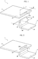
- numeral 1 indicates - in its entirety - an element in the form of a flat panel, made of plastic material, in particular composite material, including a synthetic resin reinforced with fibers, for example glass fibers, carbon fibers or polyamide fibers.
- the reference number 2 indicates - in its entirety - an element of metal material, for example, of steel or aluminum, which in the illustrated case is in the form of an angular element with a main portion 2A and a portion 2B constituting a substantially perpendicular tab with respect to the portion 2A and ending with an end portion 2B1, having a width "I" less than the width of the portions 2A, 2B.
- the element of plastic material 1 includes at least one substantially flat portion 1A.
- a through-slot 3 is formed in this portion 1A.
- Figure 1 illustrates, by way of example, the case in which a single slot 3 is formed in the element 1, this slot having a straight configuration and presenting a length L and a width W. Again in the case of the illustrated example, the slot 3 is made adjacent to one side of the panel 1, parallel to this panel.
- the dimensions L, W of the slot 3 are chosen so as to be slightly longer than the length I and the width w of the end cross-section of the tab 2B.
- the elements 1, 2 to be joined are brought into a coupling position, illustrated in Figure 2 , in which the tab 2B is inserted through the slot 3 and has its end portion 2B1 that protrudes above the upper surface 11 (with reference to the figures) of the panel 1.
- a laser welding operation is performed, using a laser torch T ( Figure 3 ) of any known type, for example a laser head for proximity welding (i.e., where the laser head is relatively close to the workpiece) or a laser head for remote welding (i.e., where the laser torch is relatively spaced apart relative to the workpiece), or a "wobbling" laser head (i.e. an oscillating laser beam).
- the laser torch is controlled and moved so as to direct a laser beam F progressively over the entire extension of the end portion 2B1 of the tab 2B that protrudes beyond the panel 1. In this way, the metal material of the end portion 2B1 is melted and produces an enlarged head 2B2 which engages against the surface 11 of the panel 1, adhering thereto.
- a hybrid component comprising the element of composite material 1 and the metal element 2 rigidly coupled to each other.
- the entire cross-section of the portion of metal material contained within the slot 3 constitutes the section resistant to a force tending to decouple the two elements 1, 2 from each other.
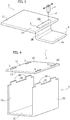
- Figures 4 , 5 and 6 show the same steps of the method according to the invention applied to an embodiment example in which the element of metal material 2 has a C-shaped conformation, with a central wall 2C, two side walls 2D parallel to each other that extend from the central wall 2C.
- Each of the side walls 2D (see Figure 4 ) has an end edge 2E from which two tabs 2A protrude and, in the coupling condition of the two elements 1, 2, illustrated in Figure 5 , each tab 2A is received through a corresponding slot 3 of the panel of composite material 1.
- the edge 2E of each lateral wall 2D comes into contact with the surface 12 of the panel 1 which, in the attached figures, is facing downwards.
- each tab 3 has an end portion 2A1 protruding beyond the surface 11 of the panel 1, which is then irradiated with the laser beam (similarly to what is shown in Figure 3 ) so as to melt and be welded above the upper surface 11 of the panel 1, forming an enlarged head 2A2.
- the panel 1 defines a fourth side of the closed cross-section of the component.
- the method according to the invention has the advantage of being simple, of not causing any significant increase in production times and costs and of allowing a joint to be obtained that is able to reliably withstand very high decoupling forces.
- the method can be used to produce hybrid components with an open or closed section, each formed by one or more elements of plastic material and by one or more elements of metal material. While the junctions between elements of plastic material and the junctions between elements of metal material can be made with any conventional art, each joint between an element of plastic material and an element of metal material is formed by the method described herein.
Landscapes
- Engineering & Computer Science (AREA)
- Mechanical Engineering (AREA)
- Physics & Mathematics (AREA)
- Optics & Photonics (AREA)
- Plasma & Fusion (AREA)
- General Engineering & Computer Science (AREA)
- Chemical & Material Sciences (AREA)
- Inorganic Chemistry (AREA)
- Crystallography & Structural Chemistry (AREA)
- Health & Medical Sciences (AREA)
- Electromagnetism (AREA)
- Toxicology (AREA)
- Lining Or Joining Of Plastics Or The Like (AREA)
- Body Structure For Vehicles (AREA)
- Laser Beam Processing (AREA)
Abstract
Description
- The present invention relates to a method for joining an element of metal material to an element of plastic material, in particular plastic material reinforced with fibers. The invention relates in particular to methods of this type used to produce hybrid components for use in the construction of motor-vehicles.
- In recent years, the automotive field has seen an increasing development in the use of hybrid components, consisting of elements of metal material and elements of plastic material connected to each other. One reason for this development is the need to reduce the weight of vehicle structures, primarily in order to reduce fuel consumption. In particular, it has been previously proposed to couple elements of metal material (for example, of steel or aluminum) with elements of composite material, including a plastic matrix reinforced with fibers, such as glass fibers, carbon fibers or polyammide fibers (kevlar). This use has also extended to the structural components of the motor-vehicle, which must be configured to safely and reliably support the stresses to which they are subjected. However, all the solutions that have been proposed up to now to produce a joint between an element of metal material and an element of plastic material forming part of a structural component of a motor-vehicle are not totally satisfactory, either because they do not guarantee a safe joint, or because they involve a risk of damage to the element of plastic material as a result of the joining operation, or because they involve relatively troublesome and complicated operations, with a consequent increase in production times and costs.
- The object of the present invention is to overcome the drawbacks of the known solutions, by providing a joining method that is simple and enables a joint to be obtained which is capable of reliably withstanding very high forces and which does not entail any appreciable increase in production times and costs.
- In view of achieving this object, the invention relates to a method for joining an element of metal material to an element of plastic material, in particular plastic material reinforced with fibers, including the steps of:
- providing one or more slots in a portion of the element of plastic material,
- for each slot of the element of plastic material, providing a corresponding tab in the first component of metal material, said tab having a cross-section with shorter width and length than the width and length of the slot,
- positioning the element of metal material and the element of plastic material in a position of mutual coupling wherein each tab of the element of metal material is inserted through a corresponding slot of the element of plastic material, and has an end portion protruding beyond said portion of the first component of metal material,
- directing a laser beam above the end portion of each tab that protrudes beyond said portion of the element of plastic material, so as to locally melt the metal material of each tab and create an enlarged head on each tab that is melted above said element of plastic material, so as to rigidly connect the element of metal material and the element of plastic material to each other.
- Thanks to the characteristics indicated above, the method according to the invention allows the joint between the element of metal material and the element of plastic material to be created without any risk of damage to the plastic material. The welding operation is carried out by locally directing a laser beam above the end portion of each tab of the element of metal material that protrudes beyond the slot in the element of plastic material. In this way, the plastic material does not substantially undergo any thermal stresses.
- The method according to the invention can be used to create structural components consisting of one or more elements of metal material and of one or more elements of plastic material defining an open section or a closed section.
- In one embodiment, the portion of the element of plastic material in which each slot is formed is substantially flat and each of the tabs formed in the component of metal material protrudes from an edge of said component which, in the coupling position of the two elements, abuts against a first surface of the aforesaid substantially flat portion of the component of plastic material.
- In an examplary embodiment, each slot formed in the element of plastic material has a substantially straight and elongated configuration, the corresponding tab having a cross-section with a corresponding configuration. However, one or more of the slots formed in the element of plastic material could have a different configuration, for example, an angled configuration, with two inclined sectons, for example perpendicular to each other, and the element of metal material could have a tab with a cross-section having a corresponding shape, or having two separate tabs designed to engage the two different sections of the same angled slot. Of course, this variant is mentioned herein by way of example only, being evident that there could be any configuration of the slots formed in the element of plastic material and the corresponding configuration of the tabs formed in the element of metal material.
- As already indicated, the method according to the invention can also be used to form structural components including one or more elements of plastic material and one or more elements of metal material, the described method being able to be adopted whenever a joint needs to be created between a metal element and a plastic element.
- Further characteristics and advantages of the invention will become apparent from the description that follows with reference to the attached drawings, provided purely by way of non-limiting example, wherein:
-
Figures 1, 2 and3 are schematic perspective views that illustrate three successive steps of the method according to the invention in a first embodiment, and -
Figures 4 ,5 and 6 are schematic perspective views showing the same steps illustrated inFigures 1-3 in the case of a second embodiment example. - With reference to
Figure 1 ,numeral 1 indicates - in its entirety - an element in the form of a flat panel, made of plastic material, in particular composite material, including a synthetic resin reinforced with fibers, for example glass fibers, carbon fibers or polyamide fibers. Thereference number 2 indicates - in its entirety - an element of metal material, for example, of steel or aluminum, which in the illustrated case is in the form of an angular element with amain portion 2A and aportion 2B constituting a substantially perpendicular tab with respect to theportion 2A and ending with an end portion 2B1, having a width "I" less than the width of theportions - Of course the specific configuration of the
elements Figure 1 is provided purely by way of non-limiting example. It is evident that there can be any configuration of each of these elements. - In the illustrated example, the element of
plastic material 1 includes at least one substantiallyflat portion 1A. In thisportion 1A, a through-slot 3 is formed.Figure 1 illustrates, by way of example, the case in which asingle slot 3 is formed in theelement 1, this slot having a straight configuration and presenting a length L and a width W. Again in the case of the illustrated example, theslot 3 is made adjacent to one side of thepanel 1, parallel to this panel. - The dimensions L, W of the
slot 3 are chosen so as to be slightly longer than the length I and the width w of the end cross-section of thetab 2B. - In the example illustrated in the method according to the invention, the
elements Figure 2 , in which thetab 2B is inserted through theslot 3 and has its end portion 2B1 that protrudes above the upper surface 11 (with reference to the figures) of thepanel 1. - Once the
elements Figure 2 , a laser welding operation is performed, using a laser torch T (Figure 3 ) of any known type, for example a laser head for proximity welding (i.e., where the laser head is relatively close to the workpiece) or a laser head for remote welding (i.e., where the laser torch is relatively spaced apart relative to the workpiece), or a "wobbling" laser head (i.e. an oscillating laser beam). The laser torch is controlled and moved so as to direct a laser beam F progressively over the entire extension of the end portion 2B1 of thetab 2B that protrudes beyond thepanel 1. In this way, the metal material of the end portion 2B1 is melted and produces an enlarged head 2B2 which engages against thesurface 11 of thepanel 1, adhering thereto. - Once the operation has been carried out, a downward movement (with reference to the figures) of the
tab 2B with respect to thepanel 1 is prevented by the engagement of the head 2B2 against theupper surface 11 of the element of plastic material. An upward movement is instead prevented by the contact between theshoulders 2E defined on the two sides of the end portion 2B1 against the lower surface of thepanel 1 - Thanks to the method described above, a hybrid component is thus obtained comprising the element of
composite material 1 and themetal element 2 rigidly coupled to each other. The entire cross-section of the portion of metal material contained within theslot 3 constitutes the section resistant to a force tending to decouple the twoelements -
Figures 4 ,5 and 6 show the same steps of the method according to the invention applied to an embodiment example in which the element ofmetal material 2 has a C-shaped conformation, with acentral wall 2C, twoside walls 2D parallel to each other that extend from thecentral wall 2C. Each of theside walls 2D (seeFigure 4 ) has anend edge 2E from which twotabs 2A protrude and, in the coupling condition of the twoelements Figure 5 , eachtab 2A is received through acorresponding slot 3 of the panel ofcomposite material 1. In the coupling condition, theedge 2E of eachlateral wall 2D comes into contact with thesurface 12 of thepanel 1 which, in the attached figures, is facing downwards. Also in this case, in the coupling condition shown inFigure 5 , eachtab 3 has an end portion 2A1 protruding beyond thesurface 11 of thepanel 1, which is then irradiated with the laser beam (similarly to what is shown inFigure 3 ) so as to melt and be welded above theupper surface 11 of thepanel 1, forming an enlarged head 2A2. In the component thus obtained, thepanel 1 defines a fourth side of the closed cross-section of the component. - The method according to the invention has the advantage of being simple, of not causing any significant increase in production times and costs and of allowing a joint to be obtained that is able to reliably withstand very high decoupling forces.
- As has been shown, the method can be used to produce hybrid components with an open or closed section, each formed by one or more elements of plastic material and by one or more elements of metal material. While the junctions between elements of plastic material and the junctions between elements of metal material can be made with any conventional art, each joint between an element of plastic material and an element of metal material is formed by the method described herein.
- Of course, without prejudice to the principle of the invention, the details of construction and the embodiments may vary widely with respect to those described and illustrated purely by way of example, without departing from the scope of the present invention, as defined by the attached claims.
Claims (7)
- A method for joining an element of metal material (2) to an element of plastic material (1), in particular plastic material reinforced with fibers, wherein the following steps are involved:- providing one or more slots (3) in a portion (1A) of said element of plastic material (1),- for each slot (3) of the element of plastic material (1), providing a corresponding tab (2B) in the element of metal material, said tab having a cross-section with shorter width (w) and a length (I) than the width (W) and length (L) of the slot (3),- arranging the element of metal material (2) and the element of plastic material (1) in a position of mutual coupling wherein each tab (2B) of the element of metal material (2) is inserted through a corresponding slot (3) of the element of plastic material (1) and has an end portion (2B1) protruding beyond said portion (1A) of the element of plastic material (1),- performing laser welding by directing a laser beam (F) above the end portion (2B1) of each tab (2B) protruding beyond said portion (1A) of the element of plastic material (1),- directing a laser beam (F) above the end portion (2B1) of each tab (2B) that protrudes beyond said portion (1A) of the element of plastic material (1), so as to locally melt the metal material of each tab (2B) and create an enlarged head (2B2) on each tab, which is welded above said element of plastic material (1), so as to rigidly connect the element of metal material (2) and the element of plastic material (1) to each other.
- A method according to claim 1, characterized in that:- the portion (1A) of the element of plastic material (1) in which each slot (3) is formed is substantially flat,- each of said tabs (2B) formed on the element of metal material (2) protrudes from an edge (2E) of the element of metal material (2),- in said coupling position, before the welding operation, said edge (2E) of the element of metal material (2) abuts against a first surface (12) of said substantially flat portion (1A) of the element of plastic material.
- A method according to claims 1 or 2, characterized in that an element of metal material (2) and an element of plastic material (1) are arranged, and configured in such a way so that in the coupled condition they define a component with a closed cross-section.
- A method according to claims 1 or 2, characterized in that an element of metal material (2) and an element of plastic material (1) are arranged, and configured in such a way so that in the coupled condition they define a component with an open cross-section.
- A method according to claim 1, characterized in that one or more slots (3) formed in the element of plastic material (1) have an angled configuration, with two inclined sides, and the element of metal material (2) has a tab with a corresponding shaped cross-section, or two separate tabs designed to engage the two different sides of the same angled slot.
- A method according to claim 3, characterized in that the element of metal material (2) has a C-shaped conformation, with a central wall (2C) and two parallel (2D) side walls, extending from the central wall (2C),
in that each of the side walls (2D) has an end edge (2E) from which more tabs (2A) protrude, and
in that in the coupling condition of the two elements of metal material and of plastic material (1, 2) each tab (2A) is received through a corresponding slot (3) of the element of plastic material (1), and
in that there is a panel in the element of plastic material (1) that defines a fourth side of a closed cross-section of the component thus obtained. - A structural component of a motor-vehicle, comprising at least one element of plastic material (1) and at least one element of metal material (2) connected by a joint obtained with the method according to one of the preceding claims.
Priority Applications (2)
| Application Number | Priority Date | Filing Date | Title |
|---|---|---|---|
| EP18167771.7A EP3556508B1 (en) | 2018-04-17 | 2018-04-17 | Method of joining an element of metal material to an element of plastic material, and a hybrid component obtained by this method |
| US16/382,279 US11219971B2 (en) | 2018-04-17 | 2019-04-12 | Method for joining an element of metal material to an element of plastic material, and a hybrid component obtained by this method |
Applications Claiming Priority (1)
| Application Number | Priority Date | Filing Date | Title |
|---|---|---|---|
| EP18167771.7A EP3556508B1 (en) | 2018-04-17 | 2018-04-17 | Method of joining an element of metal material to an element of plastic material, and a hybrid component obtained by this method |
Publications (2)
| Publication Number | Publication Date |
|---|---|
| EP3556508A1 true EP3556508A1 (en) | 2019-10-23 |
| EP3556508B1 EP3556508B1 (en) | 2020-11-25 |
Family
ID=62063310
Family Applications (1)
| Application Number | Title | Priority Date | Filing Date |
|---|---|---|---|
| EP18167771.7A Active EP3556508B1 (en) | 2018-04-17 | 2018-04-17 | Method of joining an element of metal material to an element of plastic material, and a hybrid component obtained by this method |
Country Status (2)
| Country | Link |
|---|---|
| US (1) | US11219971B2 (en) |
| EP (1) | EP3556508B1 (en) |
Families Citing this family (1)
| Publication number | Priority date | Publication date | Assignee | Title |
|---|---|---|---|---|
| WO2023100782A1 (en) * | 2021-12-02 | 2023-06-08 | 株式会社アマダ | Positioning structure and positioning method |
Citations (4)
| Publication number | Priority date | Publication date | Assignee | Title |
|---|---|---|---|---|
| DE102005035495A1 (en) * | 2005-07-26 | 2007-02-01 | Faurecia Innenraum Systeme Gmbh | Method and apparatus for laser welding |
| JP2010247206A (en) * | 2009-04-17 | 2010-11-04 | Muneharu Kutsuna | Laser processing of composite materials |
| JP2013237052A (en) * | 2012-05-11 | 2013-11-28 | Trumpf Kk | Welding method by non-contact welding |
| GB2550966A (en) * | 2016-06-03 | 2017-12-06 | The Welding Inst | Joining method using in-situ formed fasteners |
Family Cites Families (8)
| Publication number | Priority date | Publication date | Assignee | Title |
|---|---|---|---|---|
| JP4093711B2 (en) * | 2000-09-11 | 2008-06-04 | Ntn株式会社 | Peeling member |
| JP2004097550A (en) * | 2002-09-10 | 2004-04-02 | Sumitomo Rubber Ind Ltd | Golf club head and manufacturing method therefor |
| EP2039607A1 (en) * | 2007-09-19 | 2009-03-25 | Roche Diagnostics GmbH | Joining foils with laser for sterile lancets |
| WO2015085440A1 (en) * | 2013-12-13 | 2015-06-18 | Woodwelding Ag | Method for reinforcing and/or lining material |
| US10286483B2 (en) * | 2015-12-11 | 2019-05-14 | Hyperloop Technologies, Inc. | Method and system for forming laser beam weld lap-penetration joints |
| CN108884851B (en) * | 2016-03-30 | 2020-11-17 | 松下知识产权经营株式会社 | Joint structure |
| JP6998513B2 (en) * | 2017-01-31 | 2022-01-18 | パナソニックIpマネジメント株式会社 | Joined structure |
| US20180369971A1 (en) * | 2017-06-22 | 2018-12-27 | Asia Vital Components Co., Ltd. | Method of manufacturing a heat dissipation device |
-
2018
- 2018-04-17 EP EP18167771.7A patent/EP3556508B1/en active Active
-
2019
- 2019-04-12 US US16/382,279 patent/US11219971B2/en active Active
Patent Citations (4)
| Publication number | Priority date | Publication date | Assignee | Title |
|---|---|---|---|---|
| DE102005035495A1 (en) * | 2005-07-26 | 2007-02-01 | Faurecia Innenraum Systeme Gmbh | Method and apparatus for laser welding |
| JP2010247206A (en) * | 2009-04-17 | 2010-11-04 | Muneharu Kutsuna | Laser processing of composite materials |
| JP2013237052A (en) * | 2012-05-11 | 2013-11-28 | Trumpf Kk | Welding method by non-contact welding |
| GB2550966A (en) * | 2016-06-03 | 2017-12-06 | The Welding Inst | Joining method using in-situ formed fasteners |
Also Published As
| Publication number | Publication date |
|---|---|
| US11219971B2 (en) | 2022-01-11 |
| EP3556508B1 (en) | 2020-11-25 |
| US20190314933A1 (en) | 2019-10-17 |
Similar Documents
| Publication | Publication Date | Title |
|---|---|---|
| JP4191041B2 (en) | Force strut brace | |
| US9919668B2 (en) | Vehicle energy absorption structure and energy absorption member | |
| US20160362144A1 (en) | Hybrid component and method for producing the hybrid component | |
| CN103797196B (en) | The connected structure of beam and column and mating part | |
| EP1400303A2 (en) | Pin to thin plate joint and method for making the joint | |
| US8732953B2 (en) | Assembling panels edge to edge | |
| JP2015044564A (en) | Split-type cowl top cover | |
| EP2412611A1 (en) | Structure for vehicle body upper portion | |
| EP3132980B1 (en) | Vehicle frame structure | |
| RU2697335C2 (en) | Vehicle body assembly method (embodiments) and vehicle body assembly | |
| US20160318631A1 (en) | Method for connectiong fiber-reinforced structural components | |
| JP6067979B2 (en) | Wall body fixing part structure and vehicle part manufacturing method | |
| EP3556508A1 (en) | Method of joining an element of metal material to an element of plastic material, and a hybrid component obtained by this method | |
| US6387469B1 (en) | Composite part and method for producing the same | |
| CN107116997A (en) | The door of vehicle | |
| JP6521135B2 (en) | Bonding structure of vehicle members and method of bonding vehicle members | |
| EP2065166B1 (en) | Vibration-welded structure | |
| JP6112001B2 (en) | Roof joint structure for vehicles | |
| JP6293251B2 (en) | Wall body fixing part structure and vehicle part manufacturing method | |
| JP6521134B2 (en) | Bonding structure of vehicle members and method of bonding vehicle members | |
| US12043318B2 (en) | Vehicle body structure | |
| JP3945852B2 (en) | Joint structure for automotive structural members | |
| SE541042C2 (en) | A welding arrangement and a vehicle comprising such a welding arrangement | |
| US6830077B2 (en) | Method for producing a structural element with a reinforced bend and a structural element | |
| JPH0542953Y2 (en) |
Legal Events
| Date | Code | Title | Description |
|---|---|---|---|
| PUAI | Public reference made under article 153(3) epc to a published international application that has entered the european phase |
Free format text: ORIGINAL CODE: 0009012 |
|
| STAA | Information on the status of an ep patent application or granted ep patent |
Free format text: STATUS: REQUEST FOR EXAMINATION WAS MADE |
|
| STAA | Information on the status of an ep patent application or granted ep patent |
Free format text: STATUS: EXAMINATION IS IN PROGRESS |
|
| 17P | Request for examination filed |
Effective date: 20190520 |
|
| AK | Designated contracting states |
Kind code of ref document: A1 Designated state(s): AL AT BE BG CH CY CZ DE DK EE ES FI FR GB GR HR HU IE IS IT LI LT LU LV MC MK MT NL NO PL PT RO RS SE SI SK SM TR |
|
| AX | Request for extension of the european patent |
Extension state: BA ME |
|
| 17Q | First examination report despatched |
Effective date: 20191015 |
|
| RIC1 | Information provided on ipc code assigned before grant |
Ipc: B23K 101/18 20060101ALN20200604BHEP Ipc: B23K 26/60 20140101ALI20200604BHEP Ipc: B23K 26/26 20140101AFI20200604BHEP Ipc: B23K 26/323 20140101ALI20200604BHEP Ipc: B23K 103/16 20060101ALN20200604BHEP Ipc: B29C 65/00 20060101ALI20200604BHEP Ipc: B23K 103/00 20060101ALN20200604BHEP Ipc: B29C 65/16 20060101ALI20200604BHEP Ipc: B23K 26/324 20140101ALI20200604BHEP Ipc: B23K 103/18 20060101ALN20200604BHEP |
|
| GRAP | Despatch of communication of intention to grant a patent |
Free format text: ORIGINAL CODE: EPIDOSNIGR1 |
|
| STAA | Information on the status of an ep patent application or granted ep patent |
Free format text: STATUS: GRANT OF PATENT IS INTENDED |
|
| INTG | Intention to grant announced |
Effective date: 20200714 |
|
| GRAS | Grant fee paid |
Free format text: ORIGINAL CODE: EPIDOSNIGR3 |
|
| GRAA | (expected) grant |
Free format text: ORIGINAL CODE: 0009210 |
|
| STAA | Information on the status of an ep patent application or granted ep patent |
Free format text: STATUS: THE PATENT HAS BEEN GRANTED |
|
| AK | Designated contracting states |
Kind code of ref document: B1 Designated state(s): AL AT BE BG CH CY CZ DE DK EE ES FI FR GB GR HR HU IE IS IT LI LT LU LV MC MK MT NL NO PL PT RO RS SE SI SK SM TR |
|
| REG | Reference to a national code |
Ref country code: GB Ref legal event code: FG4D |
|
| REG | Reference to a national code |
Ref country code: CH Ref legal event code: EP |
|
| REG | Reference to a national code |
Ref country code: AT Ref legal event code: REF Ref document number: 1337729 Country of ref document: AT Kind code of ref document: T Effective date: 20201215 |
|
| REG | Reference to a national code |
Ref country code: DE Ref legal event code: R096 Ref document number: 602018009997 Country of ref document: DE |
|
| REG | Reference to a national code |
Ref country code: IE Ref legal event code: FG4D |
|
| REG | Reference to a national code |
Ref country code: AT Ref legal event code: MK05 Ref document number: 1337729 Country of ref document: AT Kind code of ref document: T Effective date: 20201125 |
|
| REG | Reference to a national code |
Ref country code: NL Ref legal event code: MP Effective date: 20201125 |
|
| PG25 | Lapsed in a contracting state [announced via postgrant information from national office to epo] |
Ref country code: GR Free format text: LAPSE BECAUSE OF FAILURE TO SUBMIT A TRANSLATION OF THE DESCRIPTION OR TO PAY THE FEE WITHIN THE PRESCRIBED TIME-LIMIT Effective date: 20210226 Ref country code: NO Free format text: LAPSE BECAUSE OF FAILURE TO SUBMIT A TRANSLATION OF THE DESCRIPTION OR TO PAY THE FEE WITHIN THE PRESCRIBED TIME-LIMIT Effective date: 20210225 Ref country code: RS Free format text: LAPSE BECAUSE OF FAILURE TO SUBMIT A TRANSLATION OF THE DESCRIPTION OR TO PAY THE FEE WITHIN THE PRESCRIBED TIME-LIMIT Effective date: 20201125 Ref country code: PT Free format text: LAPSE BECAUSE OF FAILURE TO SUBMIT A TRANSLATION OF THE DESCRIPTION OR TO PAY THE FEE WITHIN THE PRESCRIBED TIME-LIMIT Effective date: 20210325 Ref country code: FI Free format text: LAPSE BECAUSE OF FAILURE TO SUBMIT A TRANSLATION OF THE DESCRIPTION OR TO PAY THE FEE WITHIN THE PRESCRIBED TIME-LIMIT Effective date: 20201125 |
|
| PG25 | Lapsed in a contracting state [announced via postgrant information from national office to epo] |
Ref country code: AT Free format text: LAPSE BECAUSE OF FAILURE TO SUBMIT A TRANSLATION OF THE DESCRIPTION OR TO PAY THE FEE WITHIN THE PRESCRIBED TIME-LIMIT Effective date: 20201125 Ref country code: SE Free format text: LAPSE BECAUSE OF FAILURE TO SUBMIT A TRANSLATION OF THE DESCRIPTION OR TO PAY THE FEE WITHIN THE PRESCRIBED TIME-LIMIT Effective date: 20201125 Ref country code: PL Free format text: LAPSE BECAUSE OF FAILURE TO SUBMIT A TRANSLATION OF THE DESCRIPTION OR TO PAY THE FEE WITHIN THE PRESCRIBED TIME-LIMIT Effective date: 20201125 Ref country code: IS Free format text: LAPSE BECAUSE OF FAILURE TO SUBMIT A TRANSLATION OF THE DESCRIPTION OR TO PAY THE FEE WITHIN THE PRESCRIBED TIME-LIMIT Effective date: 20210325 Ref country code: LV Free format text: LAPSE BECAUSE OF FAILURE TO SUBMIT A TRANSLATION OF THE DESCRIPTION OR TO PAY THE FEE WITHIN THE PRESCRIBED TIME-LIMIT Effective date: 20201125 Ref country code: BG Free format text: LAPSE BECAUSE OF FAILURE TO SUBMIT A TRANSLATION OF THE DESCRIPTION OR TO PAY THE FEE WITHIN THE PRESCRIBED TIME-LIMIT Effective date: 20210225 |
|
| REG | Reference to a national code |
Ref country code: LT Ref legal event code: MG9D |
|
| PG25 | Lapsed in a contracting state [announced via postgrant information from national office to epo] |
Ref country code: HR Free format text: LAPSE BECAUSE OF FAILURE TO SUBMIT A TRANSLATION OF THE DESCRIPTION OR TO PAY THE FEE WITHIN THE PRESCRIBED TIME-LIMIT Effective date: 20201125 |
|
| PG25 | Lapsed in a contracting state [announced via postgrant information from national office to epo] |
Ref country code: EE Free format text: LAPSE BECAUSE OF FAILURE TO SUBMIT A TRANSLATION OF THE DESCRIPTION OR TO PAY THE FEE WITHIN THE PRESCRIBED TIME-LIMIT Effective date: 20201125 Ref country code: CZ Free format text: LAPSE BECAUSE OF FAILURE TO SUBMIT A TRANSLATION OF THE DESCRIPTION OR TO PAY THE FEE WITHIN THE PRESCRIBED TIME-LIMIT Effective date: 20201125 Ref country code: SM Free format text: LAPSE BECAUSE OF FAILURE TO SUBMIT A TRANSLATION OF THE DESCRIPTION OR TO PAY THE FEE WITHIN THE PRESCRIBED TIME-LIMIT Effective date: 20201125 Ref country code: SK Free format text: LAPSE BECAUSE OF FAILURE TO SUBMIT A TRANSLATION OF THE DESCRIPTION OR TO PAY THE FEE WITHIN THE PRESCRIBED TIME-LIMIT Effective date: 20201125 Ref country code: RO Free format text: LAPSE BECAUSE OF FAILURE TO SUBMIT A TRANSLATION OF THE DESCRIPTION OR TO PAY THE FEE WITHIN THE PRESCRIBED TIME-LIMIT Effective date: 20201125 Ref country code: LT Free format text: LAPSE BECAUSE OF FAILURE TO SUBMIT A TRANSLATION OF THE DESCRIPTION OR TO PAY THE FEE WITHIN THE PRESCRIBED TIME-LIMIT Effective date: 20201125 |
|
| REG | Reference to a national code |
Ref country code: DE Ref legal event code: R097 Ref document number: 602018009997 Country of ref document: DE |
|
| PG25 | Lapsed in a contracting state [announced via postgrant information from national office to epo] |
Ref country code: DK Free format text: LAPSE BECAUSE OF FAILURE TO SUBMIT A TRANSLATION OF THE DESCRIPTION OR TO PAY THE FEE WITHIN THE PRESCRIBED TIME-LIMIT Effective date: 20201125 |
|
| PLBE | No opposition filed within time limit |
Free format text: ORIGINAL CODE: 0009261 |
|
| STAA | Information on the status of an ep patent application or granted ep patent |
Free format text: STATUS: NO OPPOSITION FILED WITHIN TIME LIMIT |
|
| PG25 | Lapsed in a contracting state [announced via postgrant information from national office to epo] |
Ref country code: AL Free format text: LAPSE BECAUSE OF FAILURE TO SUBMIT A TRANSLATION OF THE DESCRIPTION OR TO PAY THE FEE WITHIN THE PRESCRIBED TIME-LIMIT Effective date: 20201125 Ref country code: NL Free format text: LAPSE BECAUSE OF FAILURE TO SUBMIT A TRANSLATION OF THE DESCRIPTION OR TO PAY THE FEE WITHIN THE PRESCRIBED TIME-LIMIT Effective date: 20201125 |
|
| 26N | No opposition filed |
Effective date: 20210826 |
|
| PG25 | Lapsed in a contracting state [announced via postgrant information from national office to epo] |
Ref country code: SI Free format text: LAPSE BECAUSE OF FAILURE TO SUBMIT A TRANSLATION OF THE DESCRIPTION OR TO PAY THE FEE WITHIN THE PRESCRIBED TIME-LIMIT Effective date: 20201125 Ref country code: MC Free format text: LAPSE BECAUSE OF FAILURE TO SUBMIT A TRANSLATION OF THE DESCRIPTION OR TO PAY THE FEE WITHIN THE PRESCRIBED TIME-LIMIT Effective date: 20201125 |
|
| PG25 | Lapsed in a contracting state [announced via postgrant information from national office to epo] |
Ref country code: LU Free format text: LAPSE BECAUSE OF NON-PAYMENT OF DUE FEES Effective date: 20210417 |
|
| REG | Reference to a national code |
Ref country code: BE Ref legal event code: MM Effective date: 20210430 |
|
| PG25 | Lapsed in a contracting state [announced via postgrant information from national office to epo] |
Ref country code: ES Free format text: LAPSE BECAUSE OF FAILURE TO SUBMIT A TRANSLATION OF THE DESCRIPTION OR TO PAY THE FEE WITHIN THE PRESCRIBED TIME-LIMIT Effective date: 20201125 Ref country code: CH Free format text: LAPSE BECAUSE OF NON-PAYMENT OF DUE FEES Effective date: 20210430 Ref country code: LI Free format text: LAPSE BECAUSE OF NON-PAYMENT OF DUE FEES Effective date: 20210430 |
|
| PG25 | Lapsed in a contracting state [announced via postgrant information from national office to epo] |
Ref country code: IE Free format text: LAPSE BECAUSE OF NON-PAYMENT OF DUE FEES Effective date: 20210417 |
|
| PG25 | Lapsed in a contracting state [announced via postgrant information from national office to epo] |
Ref country code: IS Free format text: LAPSE BECAUSE OF FAILURE TO SUBMIT A TRANSLATION OF THE DESCRIPTION OR TO PAY THE FEE WITHIN THE PRESCRIBED TIME-LIMIT Effective date: 20210325 |
|
| PG25 | Lapsed in a contracting state [announced via postgrant information from national office to epo] |
Ref country code: BE Free format text: LAPSE BECAUSE OF NON-PAYMENT OF DUE FEES Effective date: 20210430 |
|
| GBPC | Gb: european patent ceased through non-payment of renewal fee |
Effective date: 20220417 |
|
| PG25 | Lapsed in a contracting state [announced via postgrant information from national office to epo] |
Ref country code: GB Free format text: LAPSE BECAUSE OF NON-PAYMENT OF DUE FEES Effective date: 20220417 |
|
| PG25 | Lapsed in a contracting state [announced via postgrant information from national office to epo] |
Ref country code: CY Free format text: LAPSE BECAUSE OF FAILURE TO SUBMIT A TRANSLATION OF THE DESCRIPTION OR TO PAY THE FEE WITHIN THE PRESCRIBED TIME-LIMIT Effective date: 20201125 |
|
| PG25 | Lapsed in a contracting state [announced via postgrant information from national office to epo] |
Ref country code: HU Free format text: LAPSE BECAUSE OF FAILURE TO SUBMIT A TRANSLATION OF THE DESCRIPTION OR TO PAY THE FEE WITHIN THE PRESCRIBED TIME-LIMIT; INVALID AB INITIO Effective date: 20180417 |
|
| PG25 | Lapsed in a contracting state [announced via postgrant information from national office to epo] |
Ref country code: MK Free format text: LAPSE BECAUSE OF FAILURE TO SUBMIT A TRANSLATION OF THE DESCRIPTION OR TO PAY THE FEE WITHIN THE PRESCRIBED TIME-LIMIT Effective date: 20201125 |
|
| PG25 | Lapsed in a contracting state [announced via postgrant information from national office to epo] |
Ref country code: TR Free format text: LAPSE BECAUSE OF FAILURE TO SUBMIT A TRANSLATION OF THE DESCRIPTION OR TO PAY THE FEE WITHIN THE PRESCRIBED TIME-LIMIT Effective date: 20201125 |
|
| PG25 | Lapsed in a contracting state [announced via postgrant information from national office to epo] |
Ref country code: MT Free format text: LAPSE BECAUSE OF FAILURE TO SUBMIT A TRANSLATION OF THE DESCRIPTION OR TO PAY THE FEE WITHIN THE PRESCRIBED TIME-LIMIT Effective date: 20201125 |
|
| PGFP | Annual fee paid to national office [announced via postgrant information from national office to epo] |
Ref country code: FR Payment date: 20250319 Year of fee payment: 8 |
|
| PGFP | Annual fee paid to national office [announced via postgrant information from national office to epo] |
Ref country code: IT Payment date: 20250319 Year of fee payment: 8 |
|
| PGFP | Annual fee paid to national office [announced via postgrant information from national office to epo] |
Ref country code: DE Payment date: 20250319 Year of fee payment: 8 |