EP3556484B1 - Outillage intégré pour usinage par écoulement abrasif - Google Patents
Outillage intégré pour usinage par écoulement abrasif Download PDFInfo
- Publication number
- EP3556484B1 EP3556484B1 EP19168407.5A EP19168407A EP3556484B1 EP 3556484 B1 EP3556484 B1 EP 3556484B1 EP 19168407 A EP19168407 A EP 19168407A EP 3556484 B1 EP3556484 B1 EP 3556484B1
- Authority
- EP
- European Patent Office
- Prior art keywords
- cluster
- airfoil
- prong
- airfoils
- tool
- Prior art date
- Legal status (The legal status is an assumption and is not a legal conclusion. Google has not performed a legal analysis and makes no representation as to the accuracy of the status listed.)
- Active
Links
Images



Classifications
-
- B—PERFORMING OPERATIONS; TRANSPORTING
- B24—GRINDING; POLISHING
- B24B—MACHINES, DEVICES, OR PROCESSES FOR GRINDING OR POLISHING; DRESSING OR CONDITIONING OF ABRADING SURFACES; FEEDING OF GRINDING, POLISHING, OR LAPPING AGENTS
- B24B31/00—Machines or devices designed for polishing or abrading surfaces on work by means of tumbling apparatus or other apparatus in which the work and/or the abrasive material is loose; Accessories therefor
- B24B31/10—Machines or devices designed for polishing or abrading surfaces on work by means of tumbling apparatus or other apparatus in which the work and/or the abrasive material is loose; Accessories therefor involving other means for tumbling of work
- B24B31/116—Machines or devices designed for polishing or abrading surfaces on work by means of tumbling apparatus or other apparatus in which the work and/or the abrasive material is loose; Accessories therefor involving other means for tumbling of work using plastically deformable grinding compound, moved relatively to the workpiece under the influence of pressure
-
- B—PERFORMING OPERATIONS; TRANSPORTING
- B24—GRINDING; POLISHING
- B24B—MACHINES, DEVICES, OR PROCESSES FOR GRINDING OR POLISHING; DRESSING OR CONDITIONING OF ABRADING SURFACES; FEEDING OF GRINDING, POLISHING, OR LAPPING AGENTS
- B24B19/00—Single-purpose machines or devices for particular grinding operations not covered by any other main group
- B24B19/14—Single-purpose machines or devices for particular grinding operations not covered by any other main group for grinding turbine blades, propeller blades or the like
-
- B—PERFORMING OPERATIONS; TRANSPORTING
- B24—GRINDING; POLISHING
- B24C—ABRASIVE OR RELATED BLASTING WITH PARTICULATE MATERIAL
- B24C1/00—Methods for use of abrasive blasting for producing particular effects; Use of auxiliary equipment in connection with such methods
- B24C1/08—Methods for use of abrasive blasting for producing particular effects; Use of auxiliary equipment in connection with such methods for polishing surfaces, e.g. smoothing a surface by making use of liquid-borne abrasives
-
- B—PERFORMING OPERATIONS; TRANSPORTING
- B24—GRINDING; POLISHING
- B24C—ABRASIVE OR RELATED BLASTING WITH PARTICULATE MATERIAL
- B24C3/00—Abrasive blasting machines or devices; Plants
- B24C3/32—Abrasive blasting machines or devices; Plants designed for abrasive blasting of particular work, e.g. the internal surfaces of cylinder blocks
- B24C3/325—Abrasive blasting machines or devices; Plants designed for abrasive blasting of particular work, e.g. the internal surfaces of cylinder blocks for internal surfaces, e.g. of tubes
- B24C3/327—Abrasive blasting machines or devices; Plants designed for abrasive blasting of particular work, e.g. the internal surfaces of cylinder blocks for internal surfaces, e.g. of tubes by an axially-moving flow of abrasive particles without passing a blast gun, impeller or the like along the internal surface
-
- B—PERFORMING OPERATIONS; TRANSPORTING
- B24—GRINDING; POLISHING
- B24C—ABRASIVE OR RELATED BLASTING WITH PARTICULATE MATERIAL
- B24C5/00—Devices or accessories for generating abrasive blasts
-
- B—PERFORMING OPERATIONS; TRANSPORTING
- B24—GRINDING; POLISHING
- B24C—ABRASIVE OR RELATED BLASTING WITH PARTICULATE MATERIAL
- B24C7/00—Equipment for feeding abrasive material; Controlling the flowability, constitution, or other physical characteristics of abrasive blasts
- B24C7/0092—Equipment for feeding abrasive material; Controlling the flowability, constitution, or other physical characteristics of abrasive blasts the abrasive material being fed by mechanical means, e.g. by screw conveyors
-
- B—PERFORMING OPERATIONS; TRANSPORTING
- B33—ADDITIVE MANUFACTURING TECHNOLOGY
- B33Y—ADDITIVE MANUFACTURING, i.e. MANUFACTURING OF THREE-DIMENSIONAL [3D] OBJECTS BY ADDITIVE DEPOSITION, ADDITIVE AGGLOMERATION OR ADDITIVE LAYERING, e.g. BY 3D PRINTING, STEREOLITHOGRAPHY OR SELECTIVE LASER SINTERING
- B33Y80/00—Products made by additive manufacturing
-
- F—MECHANICAL ENGINEERING; LIGHTING; HEATING; WEAPONS; BLASTING
- F05—INDEXING SCHEMES RELATING TO ENGINES OR PUMPS IN VARIOUS SUBCLASSES OF CLASSES F01-F04
- F05D—INDEXING SCHEME FOR ASPECTS RELATING TO NON-POSITIVE-DISPLACEMENT MACHINES OR ENGINES, GAS-TURBINES OR JET-PROPULSION PLANTS
- F05D2230/00—Manufacture
- F05D2230/10—Manufacture by removing material
- F05D2230/14—Micromachining
-
- F—MECHANICAL ENGINEERING; LIGHTING; HEATING; WEAPONS; BLASTING
- F05—INDEXING SCHEMES RELATING TO ENGINES OR PUMPS IN VARIOUS SUBCLASSES OF CLASSES F01-F04
- F05D—INDEXING SCHEME FOR ASPECTS RELATING TO NON-POSITIVE-DISPLACEMENT MACHINES OR ENGINES, GAS-TURBINES OR JET-PROPULSION PLANTS
- F05D2240/00—Components
- F05D2240/10—Stators
- F05D2240/12—Fluid guiding means, e.g. vanes
Definitions
- the present disclosure relates generally to a cluster-tool assembly for abrasive flow machining of a plurality of airfoils and a method for polishing surfaces of a plurality of airfoils, particularly airfoil clusters for gas turbine engines.
- Abrasive flow machining is a process with application to polishing or finishing surfaces of metal parts following initial fabrication through, for example, casting or additive manufacturing.
- the process has been found to be advantageous for polishing or finishing of manufactured parts having complex structural features such as, for example, internal passages or buried cavities that include surfaces that are difficult to access by other surface finishing techniques.
- Abrasive flow machining has been employed as a manufacturing step in the production of surface finished airfoil clusters for gas turbine engines.
- the airfoil clusters may consist of a plurality of airfoils attached to a supporting rail to form a unitary structure. Due to the complex structural features of the airfoil clusters, surface polishing by abrasive flow machining may prove more effective than other polishing methods that exhibit difficulties in finishing or polishing various regions of the airfoil cluster to a desired degree.
- abrasive flow machining may provide an effective method for surface polishing of airfoil clusters
- differential finishing (or uneven surface polishing) of various regions of the airfoil clusters may occur in certain cases.
- various surfaces of the airfoil cluster may receive more surface polishing and more difficult to reach surfaces may be left with undesirable surface roughness.
- Difficult to reach surface areas may include, for example, the concave surfaces and the root radii of the airfoils and the platforms located on the support rail between each adjacent pair of airfoils.
- a cluster-tool assembly for abrasive flow machining of a plurality of airfoils is known from US 2015/375360 A1 . That document also discloses a method for polishing surfaces of a plurality of airfoils, comprising: fabricating a cluster-tool assembly, the cluster-tool assembly including an airfoil cluster and a tool associated with the airfoil cluster, wherein the airfoil cluster includes a supporting rail and the plurality of airfoils spaced about the supporting rail, wherein the associated tool comprises a body and a plurality of prongs extending from the body, wherein a first airfoil of the plurality of airfoils is positioned between a first prong and a second prong of the plurality of prongs and wherein the first airfoil includes a foil tip portion associated with the body of the tool; positioning the cluster-tool assembly within an abrasive flow machine; and flowing an abrasive media through a first side channel
- a cluster-tool assembly for abrasive flow machining of a plurality of airfoils, comprising: an airfoil cluster, the airfoil cluster including a supporting rail and the plurality of airfoils spaced about the supporting rail; and a sacrificial tool unitarily formed with the airfoil cluster, the sacrificial tool including a body and a plurality of prongs extending from the body; wherein the sacrificial tool of the cluster-tool assembly is made of a softer material than the material used to fabricate the airfoil cluster.
- a first airfoil of the plurality of airfoils is positioned between a first prong and a second prong of the plurality of prongs.
- the first airfoil includes a foil tip portion unitarily connected to the body of the sacrificial tool.
- the first airfoil defines a length from a leading edge to a trailing edge and a first side channel extends along the length between a convex foil surface of the first airfoil and a concave prong surface of the first prong.
- a second side channel extends along the length between a concave foil surface of the first airfoil and a convex prong surface of the second prong.
- the first prong includes a first prong tip portion positioned adjacent a first platform portion of the supporting rail, defining a first platform channel that extends along the length proximate a first base portion of the convex foil surface of the first airfoil.
- the second prong includes a second prong tip portion positioned adjacent a second platform portion of the supporting rail, defining a second platform channel that extends along the length proximate a second base portion of the concave foil surface of the first airfoil.
- the first side channel defines a channel width along the length
- the first platform channel defines a height along the length and the height is greater than the width.
- each one of the plurality of airfoils includes a foil tip portion unitarily connected to the body of the sacrificial tool and each one of the plurality of airfoils is positioned between a first prong and a second prong.
- each one of the plurality of airfoils includes a convex foil surface positioned adjacent a concave prong surface of the first prong and a concave foil surface positioned adjacent a convex prong surface of the second prong.
- each one of the plurality of airfoils defines a length from a leading edge to a trailing edge and a first side channel extends along the length between a first foil surface of each one of the plurality of airfoils and a first prong surface of an adjacent prong of the plurality of prongs.
- each one of the plurality of airfoils defines a length from a leading edge to a trailing edge
- a first side channel extends along the length between a convex foil surface of each one of the plurality of airfoils and a concave prong surface of a first adjacent one of the plurality of prongs
- a second side channel extends along the length between a concave foil surface of each one of the plurality of airfoils and a convex prong surface of a second adjacent one of the plurality of prongs.
- a method for polishing surfaces of a plurality of airfoils comprising: fabricating a cluster-tool assembly, the cluster-tool assembly including an airfoil cluster and a sacrificial tool unitarily formed with the airfoil cluster, the sacrificial tool of the cluster-tool assembly being made of a softer material than the material used to fabricate the airfoil cluster; wherein the airfoil cluster includes a supporting rail and the plurality of airfoils spaced about the supporting rail, wherein the sacrificial tool comprises a body and a plurality of prongs extending from the body, wherein a first airfoil of the plurality of airfoils is positioned between a first prong and a second prong of the plurality of prongs and wherein the first airfoil includes a foil tip portion unitarily connected to the body of the sacrificial tool; positioning the cluster-tool assembly within an abrasive
- the first prong includes a first prong tip portion positioned adjacent a first platform portion of the supporting rail, defining a first platform channel that extends proximate a first base portion of the convex foil surface of the first airfoil, and the abrasive media is urged through the first platform channel.
- the second prong includes a second prong tip portion positioned adjacent a second platform portion of the supporting rail, defining a second platform channel that extends proximate a second base portion of the concave foil surface of the first airfoil, and the abrasive media is urged through the second platform channel.
- the method further comprises terminating the flow of abrasive media and removing any portion of the sacrificial tool that remains connected to the airfoil cluster.
- references to "a,” “an” or “the” may include one or more than one and that reference to an item in the singular may also include the item in the plural. Further, all ranges may include upper and lower values and all ranges and ratio limits disclosed herein may be combined.
- FIG. 1 schematically illustrates a gas turbine engine 20.
- the gas turbine engine 20 is disclosed herein as a two-spool turbofan that generally incorporates a fan section 22, a compressor section 24, a combustor section 26 and a turbine section 28.
- Alternative engines might include an augmenter section (not shown) among other systems or features.
- the fan section 22 drives air along a bypass flow path B in a bypass duct defined within a nacelle 15, while the compressor section 24 drives air along a primary or core flow path C for compression and communication into the combustor section 26 and then expansion through the turbine section 28.
- the gas turbine engine 20 generally includes a low speed spool 30 and a high speed spool 32 mounted for rotation about an engine central longitudinal axis A relative to an engine static structure 36 via several bearing systems 38. It should be understood that various bearing systems at various locations may alternatively or additionally be provided and the location of the several bearing systems 38 may be varied as appropriate to the application.
- the low speed spool 30 generally includes an inner shaft 40 that interconnects a fan 42, a low pressure compressor 44 and a low pressure turbine 46.
- the inner shaft 40 is connected to the fan 42 through a speed change mechanism, which in this gas turbine engine 20 is illustrated as a fan drive gear system 48 configured to drive the fan 42 at a lower speed than the low speed spool 30.
- the high speed spool 32 includes an outer shaft 50 that interconnects a high pressure compressor 52 and a high pressure turbine 54.
- a combustor 56 is arranged in the gas turbine engine 20 between the high pressure compressor 52 and the high pressure turbine 54.
- a mid-turbine frame 57 of the engine static structure 36 is arranged generally between the high pressure turbine 54 and the low pressure turbine 46 and may include airfoils 59 in the core flow path C for guiding the flow into the low pressure turbine 46.
- the mid-turbine frame 57 further supports the several bearing systems 38 in the turbine section 28.
- the inner shaft 40 and the outer shaft 50 are concentric and rotate via the several bearing systems 38 about the engine central longitudinal axis A, which is collinear with their longitudinal axes.
- each of the positions of the fan section 22, the compressor section 24, the combustor section 26, the turbine section 28, and the fan drive gear system 48 may be varied.
- the fan drive gear system 48 may be located aft of the combustor section 26 or even aft of the turbine section 28, and the fan section 22 may be positioned forward or aft of the location of the fan drive gear system 48.
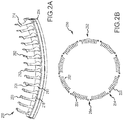
- the airfoil cluster 200 may, for example, be a cluster of vanes in a stator section of one or more of the turbine sections and the compressor sections referred to above with reference to FIG. 1 .
- the airfoil cluster 200 includes a plurality of airfoils 202 attached to a supporting rail 204.
- the airfoils 202 and the supporting rail 204 may be formed separately and then assembled to form the airfoil cluster 200.
- each of the airfoils 202 may have a leading edge 206, a trailing edge 208 and a root radii 210 near the base of the airfoils 202, as illustrated.
- each of the airfoils 202 may have a concave surface 212 (pressure side of airfoil) and a convex surface 214 (suction side of airfoil). Between each adjacent pair of the plurality of airfoils 202 may be a platform 216 along a radially inward surface of the supporting rail 204, as illustrated.
- the convex and concave surfaces of the airfoils may sometimes be referred to as convex and concave foil surfaces.
- an airfoil assembly 250 includes a plurality of airfoil clusters 252, each cluster comprising, for example, the components of the airfoil cluster 200 described above with reference to FIG. 2A .
- the plurality of airfoil clusters 252 may be interconnected at connection points 254 to form the airfoil assembly 250, which may have an annular structure, as illustrated in FIG. 2B .
- the plurality of airfoil clusters 252 includes nine individual airfoil clusters assembled to form the airfoil assembly 250.
- the airfoil assembly 250 may comprise other numbers of airfoil clusters or, in various embodiments, a single ring-like airfoil cluster.
- the airfoil assembly 250 may form a stage of a high pressure compressor of a gas turbine engine, such as, for example, the high pressure compressor 52 described above with reference to FIG. 1 .
- the airfoil assembly 250 may be a stator vane assembly forming one stage of a high pressure compressor.
- the airfoil assembly 250 may be a component of another region of a gas turbine engine, such as, for example, the rotor blades or stator vanes of the low pressure compressor or the high or low pressure turbine sections described above with reference to FIG. 1 .
- the airfoil cluster 200 may be formed from metal and be manufactured by a 3D-printing or additive manufacturing technique, such as, for example, direct metal laser sintering (DMLS). Following manufacture, in some circumstances, certain regions of the airfoil cluster 200 such as, for example, the concave surface 212, the convex surface 214, the platform 216 and the root radii 210 of each of the plurality of airfoils 202 may have rough surfaces. In order to bring the surface roughness of the various regions of the airfoil cluster 200 to a desired smoothness or to remove excess material to meet part specifications and quality regulations, the airfoil cluster 200 may require surface polishing prior to distribution and incorporation into the airfoil assembly 250 and the gas turbine engine.
- DMLS direct metal laser sintering
- such surface polishing will target areas of the airfoil cluster 200 that may be characterized by high surface roughness following manufacture (e.g., the concave surface 212, the convex surface 214, the platform 216 and the root radii 210 of each of the plurality of airfoils 202).
- high surface roughness following manufacture e.g., the concave surface 212, the convex surface 214, the platform 216 and the root radii 210 of each of the plurality of airfoils 202).
- the below disclosure provides apparatus and methods that may be employed to finish or polish the regions of high surface roughness to desirable levels, in accordance with various embodiments.
- an airfoil cluster 300 having a plurality of airfoils 302 is illustrated in combination with a sacrificial tool 320 to form a cluster-tool assembly 330.
- the cluster-tool assembly 330 is manufactured as a unitary component, using a 3D-printing or additive manufacturing technique, such as, for example, DMLS.
- a 3D-printing or additive manufacturing technique such as, for example, DMLS.
- the sacrificial tool 320 may be described as including a comb-like structure comprising a body 364 from which a plurality of prongs 366 may extend.
- Each one of the plurality of prongs 366 is dimensioned to extend between adjacent pairs of the plurality of airfoils 302 of the airfoil cluster 300 leaving spaces there between.
- the body 364 is connected between adjacent pairs of the plurality of prongs 366 to tip portions 317 corresponding to each airfoil of the plurality of airfoils 302, which results from the additive process used to fabricate the cluster-tool assembly 330 as a unitary, single-piece unit.
- each of the plurality of prongs 366 may be configured to reside between a convex surface 314 of an airfoil from the plurality of airfoils 302 and a concave surface 312 of an immediately adjacent airfoil from the plurality of airfoils 302 without coming into physical contact with the concave and convex surfaces of the airfoils.
- Each of the plurality of prongs 366 may have a length 340 in an axial direction that equals or exceeds a length of each of the plurality of airfoils 302, as measured from a leading edge to a trailing edge, such as the leading edge 206 and the trailing edge 208 described above with reference to FIG. 2A .
- each of the plurality of prongs 366 may have a concave surface 368 and a convex surface 370, each having a shape and curvature identical to, or at least substantially identical to, the concave surface 312 and the convex surface 314 of each one of the plurality of airfoils 302, respectively.
- the sacrificial tool 320 may be custom designed according to the geometry of each of the plurality of airfoils 302 of the airfoil cluster 300.
- each of the plurality of prongs 366 of the sacrificial tool 320 may define side channels 375 between each of the plurality of prongs 366 and the concave and convex surfaces of adjacent pair of airfoils.
- the side channels 375 may, for example, include a first side channel 376 formed between a concave surface 342 of a first prong 343 and a convex surface 344 of a first airfoil 378, and a second side channel 377 formed between a convex surface 345 of the first prong 343 and a concave surface 346 of a second airfoil 379, wherein the first airfoil 378 and the second airfoil 379 are immediately adjacent airfoils in the airfoil cluster 300.
- each of the side channels 375 in the cluster-tool assembly 330 has a channel width, W, which may be constant or vary along the length 340 of the side channel.
- each of the side channels 375 in the cluster-tool assembly 330 may define a flow path providing for flow of abrasive media there through during an abrasive flow polishing process and control of the velocity of the abrasive media over the concave surface 312, the convex surface 314, the leading edge, and the trailing edge of each of the plurality of airfoils 302.
- the channel width, W, of the side channels 375 may be fixed along the length 340 (from forward to aft) of the side channels 375. This arrangement may assist in providing a uniform flow velocity of the abrasive media across the surfaces of each of the plurality of airfoils 302, including the concave and convex surfaces of each of the airfoils.
- the channel width, W, of the side channels 375 may also vary depending on the polishing specifications of the airfoil cluster 300 as well as on the consistency of the abrasive media. As a non-limiting possibility, the channel width, W, of the side channels 375 may be about 0.07 inches (about 1.8 mm), but may be greater for more viscous abrasive media or lesser for less viscous abrasive media.
- the convex and concave surfaces of the airfoils may sometimes be referred to as convex and concave foil surfaces.
- the convex and concave surfaces of the prongs may sometimes be referred to as convex and concave prong surfaces.
- each of the plurality of prongs 366 of the sacrificial tool 320 may have a tip portion 380 that, when manufactured unitarily with the airfoil cluster 300, may be positioned adjacent a platform 316, which defines a platform channel 382 there between.
- the abrasive media may flow through the platform channel 382 during the abrasive flow polishing process and the platform channel 382 may assist in controlling the velocity of the flow of the abrasive media over the surfaces of both the platform 322 and a corresponding pair of root radii 310.
- Each platform channel 382 may have a channel height, H, as measured by the distance from the tip portion 380 of each of the plurality of prongs 366 to the platform 322 corresponding thereto.
- each channel height, H may be greater than the channel width, W, of the side channels 375.
- the channel height, H, of the platform channel 382 may be up to about two times greater than the channel width, W, of the side channels 375.
- the channel height, H, of each platform channel 382 may be about 0.14 inches (about 3.6 mm) wide, but other channel heights are certainly possible depending on the airfoil cluster geometry or the viscosity of the abrasive media.
- the channel height, H, of the platform channel 382 may be equal to or less than the channel width, W, of the side channels 375.
- the cluster-tool assembly 330 may assist in targeting certain surfaces of the airfoil cluster 300 for enhanced polishing. More specifically, given that the velocity of the flow of the abrasive media through the side channels 375 and each platform channel 382 may be directly correlated with the channel width, W, and the channel height, H, and that each platform channel 382 may be wider than the side channels 375, the abrasive media may flow with higher velocities in the platform channel 382 than in the side channels 375 during the abrasive flow polishing process.
- the surfaces of the airfoil cluster 300 that are located in each platform channel 382 may experience greater abrasive wear and enhanced polishing as compared to the surfaces located in the side channels 375.
- the channel width, W, and the channel height, H may be adjusted relative to one another to enhance the polishing of the concave and convex surfaces of each airfoil relative to the platform and root radii surfaces.
- the channel width, W may vary along the span or length of each airfoil, from root to tip, to enhance polishing at, for example, the tip of the airfoil relative to the root of the airfoil.
- the sacrificial tool 320 may have alternative configurations creating different flow channel geometries to direct enhanced abrasive activity to other selected regions of the airfoil cluster 300.
- an abrasive flow machine 400 configured for abrasive flow polishing of one or more cluster-tool assemblies 430, such as the cluster-tool assembly 330, comprising the airfoil cluster 300 and the sacrificial tool 320, described above with reference to FIGS. 3A and 3B is illustrated.
- the abrasive flow machine 400 comprises a housing 402 for containing an abrasive media 404.
- the abrasive media 404 may have a viscous, gel-like or putty-like consistency and it may be permeated with an abrasive material that may act to abrade and polish surfaces of one or more airfoil clusters 406 and wear away the material comprising one or more sacrificial tools 408 corresponding to the airfoil clusters 406.
- the abrasive flow machine 400 may include a fixture 410 configured to retain each of the cluster-tool assemblies 430, which comprise the airfoil clusters 406 and sacrificial tools 408, in a static position during the abrasive flow polishing process.
- the abrasive flow machine 400 may include a driver 412 to cause the abrasive media 404 to flow over the surfaces of the cluster-tool assemblies 430.
- the driver 412 may drive a pair of opposing pistons 422 to direct the abrasive media 404 back and forth in a reciprocating motion between an upper chamber 414 and a lower chamber 416 of the housing 402.
- the pair of opposing pistons 422 direct the abrasive media 404 in a forward direction 418, causing the abrasive media 404 to flow from the upper chamber 414 to the lower chamber 416, and in a reverse direction 420, causing the abrasive media 404 to flow from the lower chamber 416 to the upper chamber 414.
- the abrasive media 404 flows back and forth over the surfaces of the cluster-tool assemblies 430, including the airfoil clusters 406 and the sacrificial tools 408.
- the fixture 410 may retain a plurality of the cluster-tool assemblies 430 during abrasive flow polishing.
- FIG. 5 a schematic depiction of the flow of abrasive media 504 through a cross section of a cluster-tool assembly 530, such as the cluster-tool assembly 330 described above with reference to FIGS. 3A and 3B is illustrated.
- the cluster-tool assembly comprises a plurality of airfoils 502 positioned between a plurality of prongs 566.
- a plurality of side channels 575 such as the side channels 375 described above with reference to FIGS. 3A and 3B , extend along a length of each of the plurality of airfoils 502.
- Each of the side channels 575 may have a curvature that matches, or at least substantially matches, the curvature of the concave and convex surfaces of the plurality of airfoils 502. Accordingly, the flow of the abrasive media 504 in both a forward direction 518 and the reverse direction 520 may follow a curved pathway 585 having a curvature that matches, or at least substantially matches, the curvature of each of the plurality of airfoils 502.
- a method 600 for finishing or polishing a plurality of airfoils within a cluster-tool assembly comprising an airfoil cluster and a sacrificial tool.
- a cluster-tool assembly comprising an airfoil cluster and a sacrificial tool.
- the cluster-tool assemblies may be fabricated using an additive process.
- the material used to fabricate the sacrificial portion of the cluster-tool assembly is made of a softer material than the material used to fabricate the airfoil cluster.
- the cluster-tool assemblies are positioned within and secured to a fixture and the fixture is placed within an abrasive flow machine.
- abrasive flow machining is performed.
- the abrasive flow machining such as that described above with reference to FIGS. 4A and 4B , contemplates reciprocating motion of an abrasive material through side channels and platform channels within the cluster-tool assemblies, such that the airfoils are polished while the sacrificial tool is abraded away.
- the curvature and geometries of the side channels and the platform channels may assist in controlling the direction and velocity of the flow of the abrasive media over the surfaces of the airfoil cluster in order to target specific regions (e.g ., the concave and convex airfoil surfaces, the platforms and the root radii) of the airfoil clusters for enhanced abrasion and polishing or to assist preventing abrasive wear on selected regions of the airfoil.
- any residual material from the sacrificial tools is removed from the airfoil clusters.
- the foregoing provides an apparatus and method that may be used to enhance post-processing (e.g ., finishing or polishing) of components by abrasive flow machining. This is accomplished by fabricating a sacrificial tool into the component (e.g ., an airfoil cluster) and exposing the combination to abrasive flow media.
- the sacrificial component is configured to beneficially guide the abrasive flow media toward regions of the component that are either difficult to reach or require focused smoothing or polishing of undesired roughness.
- the terms “comprises”, “comprising”, or any other variation thereof, are intended to cover a non-exclusive inclusion, such that a process, method, article, or apparatus that comprises a list of elements does not include only those elements but may include other elements not expressly listed or inherent to such process, method, article, or apparatus.
Landscapes
- Engineering & Computer Science (AREA)
- Mechanical Engineering (AREA)
- Finish Polishing, Edge Sharpening, And Grinding By Specific Grinding Devices (AREA)
Claims (15)
- Ensemble d'outils groupés (330 ; 530) pour usinage par écoulement abrasif d'une pluralité de profils aérodynamiques (302 ; 502), comprenant :un groupe de profils aérodynamiques (200, 252 ; 300 ; 406), le groupe de profils aérodynamiques (200, 252 ; 300 ; 406) comportant un rail de support (204) et la pluralité de profils aérodynamiques (302 ; 502) espacés autour du rail de support (204) ; et caractérisé parun outil sacrificiel (320) formé d'un seul tenant avec le groupe de profils aérodynamiques (200, 252 ; 300 ; 406), l'outil sacrificiel (320) comportant un corps (364) et une pluralité de dents (366) s'étendant depuis le corps (364) ;dans lequel l'outil sacrificiel (320) de l'ensemble d'outils groupés (330 ; 530) est constitué d'un matériau plus souple que le matériau utilisé pour fabriquer le groupe de profils aérodynamiques (200, 252 ; 300 ; 406).
- Ensemble d'outils groupés (330 ; 530) selon la revendication 1, dans lequel un premier profil aérodynamique (378) de la pluralité de profils aérodynamiques (302 ; 502) est positionné entre une première dent (343) et une seconde dent de la pluralité de dents (366).
- Ensemble d'outils groupés (330 ; 530) selon la revendication 2, dans lequel le premier profil aérodynamique (378) comporte une partie d'extrémité portante (380) reliée d'un seul tenant au corps (364) de l'outil sacrificiel (320).
- Ensemble d'outils groupés (330 ; 530) selon la revendication 3, dans lequel le premier profil aérodynamique (378) définit une longueur depuis un bord d'attaque (206) vers un bord de fuite (208) et dans lequel un premier canal latéral (376) s'étend sur la longueur entre une surface portante convexe (344) du premier profil aérodynamique (378) et une surface de dent concave (342) de la première dent (343).
- Ensemble d'outils groupés (330 ; 530) selon la revendication 4, dans lequel un second canal latéral (377) s'étend sur la longueur entre une surface portante concave (346) du premier profil aérodynamique (378) et une surface de dent convexe (345) de la seconde dent.
- Ensemble d'outils groupés (330 ; 530) selon la revendication 5, dans lequel la première dent (343) comporte une première partie d'extrémité de dent (380) positionnée de manière adjacente à une première partie de plate-forme (316) du rail de support (204), définissant un premier canal de plate-forme (382) qui s'étend sur la longueur à proximité d'une première partie de base de la surface portante convexe (344) du premier profil aérodynamique (378).
- Ensemble d'outils groupés (330 ; 530) selon la revendication 6, dans lequel la seconde dent comporte une seconde partie d'extrémité de dent (380) positionnée de manière adjacente à une seconde partie de plate-forme (316) du rail de support (204), définissant un second canal de plate-forme (382) qui s'étend sur la longueur à proximité d'une seconde partie de base de la surface portante concave (346) du premier profil aérodynamique (378),
- Ensemble d'outils groupés (330 ; 530) selon la revendication 6 ou 7, dans lequel le premier canal latéral (376) définit une largeur de canal sur la longueur, dans lequel le premier canal de plate-forme (382) définit une hauteur de canal sur la longueur et dans lequel la hauteur de canal est supérieure à la largeur de canal.
- Ensemble d'outils groupés (330 ; 530) selon l'une quelconque des revendications 1 à 8, dans lequel chacun de la pluralité de profils aérodynamiques (302 ; 502) comporte une partie d'extrémité portante (380) reliée d'un seul tenant au corps (364) de l'outil sacrificiel (320) et dans lequel chacun de la pluralité de profils aérodynamiques (302 ; 502) est positionné entre une première dent (343) et une seconde dent.
- Ensemble d'outils groupés selon la revendication 9, dans lequel chacun de la pluralité de profils aérodynamiques (302 ; 502) comporte une surface portante convexe (344) positionnée de manière adjacente à une surface de dent concave (342) de la première dent (343) et une surface portante concave (346) positionnée de manière adjacente à une surface de dent convexe (345) de la seconde dent.
- Ensemble d'outils groupés (330 ; 530) selon la revendication 10, dans lequel chacun de la pluralité de profils aérodynamiques (302 ; 502) définit une longueur depuis un bord d'attaque (206) vers un bord de fuite (208) et dans lequel un premier canal latéral (376) s'étend sur la longueur entre une première surface portante de chacun de la pluralité de profils aérodynamiques (302 ; 502) et une première surface de dent d'une dent adjacente de la pluralité de dents (366).
- Ensemble d'outils groupés (330 ; 530) selon la revendication 9, 10 ou 11, dans lequel chacun de la pluralité de profils aérodynamiques (302 ; 502) définit une longueur depuis un bord d'attaque (206) vers un bord de fuite (208) et dans lequel un premier canal latéral (376) s'étend sur la longueur entre une surface portante convexe (344) de chacun de la pluralité de profils aérodynamiques (302 ; 502) et une surface de dent concave (342) d'une première dent adjacente de la pluralité de dents (366) et dans lequel un second canal latéral (377) s'étend sur la longueur entre une surface portante concave (346) de chacun de la pluralité de profils aérodynamiques (302 ; 502) et une surface de dent convexe (345) d'une seconde dent adjacente de la pluralité de dents (366).
- Procédé de polissage de surfaces d'une pluralité de profils aérodynamiques (302 ; 502), comprenant :la fabrication d'un ensemble d'outils groupés (330 ; 530), l'ensemble d'outils groupés (330 ; 530) comportant un groupe de profils aérodynamiques (200, 252 ; 300 ; 406) et un outil sacrificiel (320) formé d'un seul tenant avec le groupe de profils aérodynamiques (200, 252 ; 300 ; 406), l'outil sacrificiel (320) de l'ensemble d'outils groupés (330 ; 530) étant constitué d'un matériau plus souple que le matériau utilisé pour fabriquer le groupe de profils aérodynamiques (200, 252 ; 300 ; 406) ;dans lequel le groupe de profils aérodynamiques (200, 252 ; 300 ; 406) comporte un rail de support (204) et la pluralité de profils aérodynamiques (302 ; 502) espacés autour du rail de support (204), dans lequel l'outil sacrificiel (320) comprend un corps (364) et une pluralité de dents (366) s'étendant depuis le corps (364), dans lequel un premier profil aérodynamique (378) de la pluralité de profils aérodynamiques (302 ; 502) est positionné entre une première dent (343) et une seconde dent de la pluralité de dents (366) et dans lequel le premier profil aérodynamique (378) comporte une partie d'extrémité portante (380) reliée d'un seul tenant au corps (364) de l'outil sacrificiel (320) ;le positionnement de l'ensemble d'outils groupés (330 ; 530) à l'intérieur d'une machine à écoulement abrasif (400) ; etl'écoulement d'un milieu abrasif (404) à travers un premier canal latéral (376) s'étendant entre une surface portante convexe (344) du premier profil aérodynamique (378) et une surface de dent concave (342) de la première dent (343) et un second canal latéral (377) s'étendant entre une surface portante concave (346) du premier profil aérodynamique (378) et une surface de dent convexe (345) de la seconde dent.
- Procédé selon la revendication 13, dans lequel la première dent (343) comporte une première partie d'extrémité de dent (380) positionnée de manière adjacente à une première partie de plate-forme (316) du rail de support (204), définissant un premier canal de plate-forme (382) qui s'étend à proximité d'une première partie de base de la surface portante convexe (344) du premier profil aérodynamique (378) et dans lequel le milieu abrasif (404) est poussé à travers le premier canal de plate-forme (382),
dans lequel, éventuellement, la seconde dent comporte une seconde partie d'extrémité de dent (380) positionnée de manière adjacente à une seconde partie de plate-forme (316) du rail de support (204), définissant un second canal de plate-forme (382) qui s'étend à proximité d'une seconde partie de base de la surface portante concave (346) du premier profil aérodynamique (378) et dans lequel le milieu abrasif (404) est poussé à travers le second canal de plate-forme (382). - Procédé selon la revendication 13 ou la revendication 14, comprenant en outre l'arrêt de l'écoulement de milieu abrasif (404) et le retrait de toute partie de l'outil sacrificiel (320) qui reste reliée au groupe de profils aérodynamiques (200, 252 ; 300 ; 406) .
Applications Claiming Priority (1)
| Application Number | Priority Date | Filing Date | Title |
|---|---|---|---|
| US15/957,759 US20190321934A1 (en) | 2018-04-19 | 2018-04-19 | Integrated tooling for abrasive flow machining |
Publications (2)
| Publication Number | Publication Date |
|---|---|
| EP3556484A1 EP3556484A1 (fr) | 2019-10-23 |
| EP3556484B1 true EP3556484B1 (fr) | 2021-08-11 |
Family
ID=66105053
Family Applications (1)
| Application Number | Title | Priority Date | Filing Date |
|---|---|---|---|
| EP19168407.5A Active EP3556484B1 (fr) | 2018-04-19 | 2019-04-10 | Outillage intégré pour usinage par écoulement abrasif |
Country Status (2)
| Country | Link |
|---|---|
| US (1) | US20190321934A1 (fr) |
| EP (1) | EP3556484B1 (fr) |
Family Cites Families (6)
| Publication number | Priority date | Publication date | Assignee | Title |
|---|---|---|---|---|
| EP1438158B1 (fr) * | 2001-09-21 | 2007-03-21 | Extrude Hone Corporation | Appareil et procede pour usinage par flux d'abrasion |
| US6780089B2 (en) * | 2002-12-03 | 2004-08-24 | General Electric Company | Method and apparatus for removing a predetermined amount of material from a bottom portion of a dovetail slot in gas turbine engine disk |
| DE10309456A1 (de) * | 2003-03-05 | 2004-09-16 | Mtu Aero Engines Gmbh | Vorrichtung und Verfahren zur Oberflächenbearbeitung eines Werkstückes |
| US9550267B2 (en) * | 2013-03-15 | 2017-01-24 | United Technologies Corporation | Tool for abrasive flow machining of airfoil clusters |
| EP3062961B1 (fr) * | 2013-10-28 | 2020-11-25 | United Technologies Corporation | Système de polissage de surfaces portantes |
| US20170080543A1 (en) * | 2015-09-22 | 2017-03-23 | Delavan Inc | Additive manufacture of interior passages |
-
2018
- 2018-04-19 US US15/957,759 patent/US20190321934A1/en not_active Abandoned
-
2019
- 2019-04-10 EP EP19168407.5A patent/EP3556484B1/fr active Active
Non-Patent Citations (1)
| Title |
|---|
| None * |
Also Published As
| Publication number | Publication date |
|---|---|
| EP3556484A1 (fr) | 2019-10-23 |
| US20190321934A1 (en) | 2019-10-24 |
Similar Documents
| Publication | Publication Date | Title |
|---|---|---|
| EP1792680B1 (fr) | Procédé d'usinage de composants de moteurs de turbine | |
| EP3617451B1 (fr) | Aube à élément poreux abradable et procédé d'usinage associé | |
| EP3030751B1 (fr) | Composant de moteur à turbine à gaz et procédé associé de formation d'un composant de moteur à turbine à gaz | |
| US8286348B2 (en) | Method of manufacturing and refinishing integrally bladed rotors | |
| EP3196416B1 (fr) | Noyau d'épaisseur variable pour la production de composants refroidis de moteur à turbine à gaz | |
| EP3056674B1 (fr) | Article possédant un passage de refroidissement avec profil ondulé | |
| US9550267B2 (en) | Tool for abrasive flow machining of airfoil clusters | |
| US11014190B2 (en) | Hollow airfoil with catenary profiles | |
| JP2000199402A (ja) | 先端を切断した面取り部を持つタ―ビン動翼 | |
| EP4431700A1 (fr) | Procédé d'adaptation des caractéristiques vibratoires d'un couvercle pour un agencement d'aube creuse à corps ouvert, agencement d'aube creuse et procédé de modification d'une caractéristique vibratoire d'un couvercle à un corps ouvert | |
| US20140377070A1 (en) | Axial Turbomachine Compressor Drum with Dual Means of Blade Fixing | |
| US9840926B2 (en) | Abrasive flow media fixture with end contour | |
| EP3219922B1 (fr) | Segment d'arc d'étanchéité ayant une fonction anti-rotation | |
| EP3556484B1 (fr) | Outillage intégré pour usinage par écoulement abrasif | |
| WO2014143302A1 (fr) | Outil pour l'usinage par écoulement abrasif d'ensembles de surfaces portantes | |
| US11773726B2 (en) | Angled tip rods | |
| US12571329B2 (en) | Altering structural response of two-piece hollow-vane assembly | |
| US8020296B2 (en) | Method for the production of secondary fluid ducts | |
| US20170001280A1 (en) | Vibratory mass media fixture with tip protector | |
| EP3246533B1 (fr) | Passages de refroidissement formés pour joint d'air extérieur d'aube de turbine | |
| EP3571413B1 (fr) | Rugosité de surface zonée | |
| US12215597B1 (en) | Gas turbine engine rotor blade geometry and method for selecting same | |
| EP4431701A1 (fr) | Procédé d'adaptation des caractéristiques vibratoires d'un couvercle pour un agencement d'aube creuse à corps ouvert, agencement d'aube creuse et procédé de modification d'une caractéristique vibratoire d'un couvercle à un corps ouvert | |
| EP3623575A1 (fr) | Couvercle de virage en serpentin pour ensemble aube de stator de turbine à gaz | |
| EP4675087A1 (fr) | Procédé d'accordement ou de modification d'une caractéristique vibratoire pour un agencement d'aube creuse à corps ouvert, et agencement d'aube creuse |
Legal Events
| Date | Code | Title | Description |
|---|---|---|---|
| PUAI | Public reference made under article 153(3) epc to a published international application that has entered the european phase |
Free format text: ORIGINAL CODE: 0009012 |
|
| STAA | Information on the status of an ep patent application or granted ep patent |
Free format text: STATUS: THE APPLICATION HAS BEEN PUBLISHED |
|
| AK | Designated contracting states |
Kind code of ref document: A1 Designated state(s): AL AT BE BG CH CY CZ DE DK EE ES FI FR GB GR HR HU IE IS IT LI LT LU LV MC MK MT NL NO PL PT RO RS SE SI SK SM TR |
|
| AX | Request for extension of the european patent |
Extension state: BA ME |
|
| STAA | Information on the status of an ep patent application or granted ep patent |
Free format text: STATUS: REQUEST FOR EXAMINATION WAS MADE |
|
| STAA | Information on the status of an ep patent application or granted ep patent |
Free format text: STATUS: EXAMINATION IS IN PROGRESS |
|
| 17P | Request for examination filed |
Effective date: 20200421 |
|
| RBV | Designated contracting states (corrected) |
Designated state(s): AL AT BE BG CH CY CZ DE DK EE ES FI FR GB GR HR HU IE IS IT LI LT LU LV MC MK MT NL NO PL PT RO RS SE SI SK SM TR |
|
| 17Q | First examination report despatched |
Effective date: 20200514 |
|
| GRAP | Despatch of communication of intention to grant a patent |
Free format text: ORIGINAL CODE: EPIDOSNIGR1 |
|
| STAA | Information on the status of an ep patent application or granted ep patent |
Free format text: STATUS: GRANT OF PATENT IS INTENDED |
|
| RAP1 | Party data changed (applicant data changed or rights of an application transferred) |
Owner name: RAYTHEON TECHNOLOGIES CORPORATION |
|
| INTG | Intention to grant announced |
Effective date: 20210301 |
|
| GRAS | Grant fee paid |
Free format text: ORIGINAL CODE: EPIDOSNIGR3 |
|
| GRAA | (expected) grant |
Free format text: ORIGINAL CODE: 0009210 |
|
| STAA | Information on the status of an ep patent application or granted ep patent |
Free format text: STATUS: THE PATENT HAS BEEN GRANTED |
|
| AK | Designated contracting states |
Kind code of ref document: B1 Designated state(s): AL AT BE BG CH CY CZ DE DK EE ES FI FR GB GR HR HU IE IS IT LI LT LU LV MC MK MT NL NO PL PT RO RS SE SI SK SM TR |
|
| REG | Reference to a national code |
Ref country code: CH Ref legal event code: EP |
|
| REG | Reference to a national code |
Ref country code: DE Ref legal event code: R096 Ref document number: 602019006715 Country of ref document: DE |
|
| REG | Reference to a national code |
Ref country code: IE Ref legal event code: FG4D Ref country code: AT Ref legal event code: REF Ref document number: 1418855 Country of ref document: AT Kind code of ref document: T Effective date: 20210915 |
|
| REG | Reference to a national code |
Ref country code: LT Ref legal event code: MG9D |
|
| REG | Reference to a national code |
Ref country code: NL Ref legal event code: MP Effective date: 20210811 |
|
| REG | Reference to a national code |
Ref country code: AT Ref legal event code: MK05 Ref document number: 1418855 Country of ref document: AT Kind code of ref document: T Effective date: 20210811 |
|
| PG25 | Lapsed in a contracting state [announced via postgrant information from national office to epo] |
Ref country code: HR Free format text: LAPSE BECAUSE OF FAILURE TO SUBMIT A TRANSLATION OF THE DESCRIPTION OR TO PAY THE FEE WITHIN THE PRESCRIBED TIME-LIMIT Effective date: 20210811 Ref country code: NO Free format text: LAPSE BECAUSE OF FAILURE TO SUBMIT A TRANSLATION OF THE DESCRIPTION OR TO PAY THE FEE WITHIN THE PRESCRIBED TIME-LIMIT Effective date: 20211111 Ref country code: PT Free format text: LAPSE BECAUSE OF FAILURE TO SUBMIT A TRANSLATION OF THE DESCRIPTION OR TO PAY THE FEE WITHIN THE PRESCRIBED TIME-LIMIT Effective date: 20211213 Ref country code: BG Free format text: LAPSE BECAUSE OF FAILURE TO SUBMIT A TRANSLATION OF THE DESCRIPTION OR TO PAY THE FEE WITHIN THE PRESCRIBED TIME-LIMIT Effective date: 20211111 Ref country code: AT Free format text: LAPSE BECAUSE OF FAILURE TO SUBMIT A TRANSLATION OF THE DESCRIPTION OR TO PAY THE FEE WITHIN THE PRESCRIBED TIME-LIMIT Effective date: 20210811 Ref country code: LT Free format text: LAPSE BECAUSE OF FAILURE TO SUBMIT A TRANSLATION OF THE DESCRIPTION OR TO PAY THE FEE WITHIN THE PRESCRIBED TIME-LIMIT Effective date: 20210811 Ref country code: SE Free format text: LAPSE BECAUSE OF FAILURE TO SUBMIT A TRANSLATION OF THE DESCRIPTION OR TO PAY THE FEE WITHIN THE PRESCRIBED TIME-LIMIT Effective date: 20210811 Ref country code: RS Free format text: LAPSE BECAUSE OF FAILURE TO SUBMIT A TRANSLATION OF THE DESCRIPTION OR TO PAY THE FEE WITHIN THE PRESCRIBED TIME-LIMIT Effective date: 20210811 Ref country code: ES Free format text: LAPSE BECAUSE OF FAILURE TO SUBMIT A TRANSLATION OF THE DESCRIPTION OR TO PAY THE FEE WITHIN THE PRESCRIBED TIME-LIMIT Effective date: 20210811 Ref country code: FI Free format text: LAPSE BECAUSE OF FAILURE TO SUBMIT A TRANSLATION OF THE DESCRIPTION OR TO PAY THE FEE WITHIN THE PRESCRIBED TIME-LIMIT Effective date: 20210811 |
|
| PG25 | Lapsed in a contracting state [announced via postgrant information from national office to epo] |
Ref country code: PL Free format text: LAPSE BECAUSE OF FAILURE TO SUBMIT A TRANSLATION OF THE DESCRIPTION OR TO PAY THE FEE WITHIN THE PRESCRIBED TIME-LIMIT Effective date: 20210811 Ref country code: LV Free format text: LAPSE BECAUSE OF FAILURE TO SUBMIT A TRANSLATION OF THE DESCRIPTION OR TO PAY THE FEE WITHIN THE PRESCRIBED TIME-LIMIT Effective date: 20210811 Ref country code: GR Free format text: LAPSE BECAUSE OF FAILURE TO SUBMIT A TRANSLATION OF THE DESCRIPTION OR TO PAY THE FEE WITHIN THE PRESCRIBED TIME-LIMIT Effective date: 20211112 |
|
| PG25 | Lapsed in a contracting state [announced via postgrant information from national office to epo] |
Ref country code: NL Free format text: LAPSE BECAUSE OF FAILURE TO SUBMIT A TRANSLATION OF THE DESCRIPTION OR TO PAY THE FEE WITHIN THE PRESCRIBED TIME-LIMIT Effective date: 20210811 |
|
| PG25 | Lapsed in a contracting state [announced via postgrant information from national office to epo] |
Ref country code: DK Free format text: LAPSE BECAUSE OF FAILURE TO SUBMIT A TRANSLATION OF THE DESCRIPTION OR TO PAY THE FEE WITHIN THE PRESCRIBED TIME-LIMIT Effective date: 20210811 |
|
| REG | Reference to a national code |
Ref country code: DE Ref legal event code: R097 Ref document number: 602019006715 Country of ref document: DE |
|
| PG25 | Lapsed in a contracting state [announced via postgrant information from national office to epo] |
Ref country code: SM Free format text: LAPSE BECAUSE OF FAILURE TO SUBMIT A TRANSLATION OF THE DESCRIPTION OR TO PAY THE FEE WITHIN THE PRESCRIBED TIME-LIMIT Effective date: 20210811 Ref country code: SK Free format text: LAPSE BECAUSE OF FAILURE TO SUBMIT A TRANSLATION OF THE DESCRIPTION OR TO PAY THE FEE WITHIN THE PRESCRIBED TIME-LIMIT Effective date: 20210811 Ref country code: RO Free format text: LAPSE BECAUSE OF FAILURE TO SUBMIT A TRANSLATION OF THE DESCRIPTION OR TO PAY THE FEE WITHIN THE PRESCRIBED TIME-LIMIT Effective date: 20210811 Ref country code: EE Free format text: LAPSE BECAUSE OF FAILURE TO SUBMIT A TRANSLATION OF THE DESCRIPTION OR TO PAY THE FEE WITHIN THE PRESCRIBED TIME-LIMIT Effective date: 20210811 Ref country code: CZ Free format text: LAPSE BECAUSE OF FAILURE TO SUBMIT A TRANSLATION OF THE DESCRIPTION OR TO PAY THE FEE WITHIN THE PRESCRIBED TIME-LIMIT Effective date: 20210811 Ref country code: AL Free format text: LAPSE BECAUSE OF FAILURE TO SUBMIT A TRANSLATION OF THE DESCRIPTION OR TO PAY THE FEE WITHIN THE PRESCRIBED TIME-LIMIT Effective date: 20210811 |
|
| PLBE | No opposition filed within time limit |
Free format text: ORIGINAL CODE: 0009261 |
|
| STAA | Information on the status of an ep patent application or granted ep patent |
Free format text: STATUS: NO OPPOSITION FILED WITHIN TIME LIMIT |
|
| 26N | No opposition filed |
Effective date: 20220512 |
|
| PG25 | Lapsed in a contracting state [announced via postgrant information from national office to epo] |
Ref country code: IT Free format text: LAPSE BECAUSE OF FAILURE TO SUBMIT A TRANSLATION OF THE DESCRIPTION OR TO PAY THE FEE WITHIN THE PRESCRIBED TIME-LIMIT Effective date: 20210811 |
|
| PG25 | Lapsed in a contracting state [announced via postgrant information from national office to epo] |
Ref country code: SI Free format text: LAPSE BECAUSE OF FAILURE TO SUBMIT A TRANSLATION OF THE DESCRIPTION OR TO PAY THE FEE WITHIN THE PRESCRIBED TIME-LIMIT Effective date: 20210811 |
|
| REG | Reference to a national code |
Ref country code: CH Ref legal event code: PL |
|
| REG | Reference to a national code |
Ref country code: BE Ref legal event code: MM Effective date: 20220430 |
|
| PG25 | Lapsed in a contracting state [announced via postgrant information from national office to epo] |
Ref country code: MC Free format text: LAPSE BECAUSE OF FAILURE TO SUBMIT A TRANSLATION OF THE DESCRIPTION OR TO PAY THE FEE WITHIN THE PRESCRIBED TIME-LIMIT Effective date: 20210811 Ref country code: LU Free format text: LAPSE BECAUSE OF NON-PAYMENT OF DUE FEES Effective date: 20220410 Ref country code: LI Free format text: LAPSE BECAUSE OF NON-PAYMENT OF DUE FEES Effective date: 20220430 Ref country code: CH Free format text: LAPSE BECAUSE OF NON-PAYMENT OF DUE FEES Effective date: 20220430 |
|
| PG25 | Lapsed in a contracting state [announced via postgrant information from national office to epo] |
Ref country code: BE Free format text: LAPSE BECAUSE OF NON-PAYMENT OF DUE FEES Effective date: 20220430 |
|
| PG25 | Lapsed in a contracting state [announced via postgrant information from national office to epo] |
Ref country code: IE Free format text: LAPSE BECAUSE OF NON-PAYMENT OF DUE FEES Effective date: 20220410 |
|
| P01 | Opt-out of the competence of the unified patent court (upc) registered |
Effective date: 20230521 |
|
| PG25 | Lapsed in a contracting state [announced via postgrant information from national office to epo] |
Ref country code: HU Free format text: LAPSE BECAUSE OF FAILURE TO SUBMIT A TRANSLATION OF THE DESCRIPTION OR TO PAY THE FEE WITHIN THE PRESCRIBED TIME-LIMIT; INVALID AB INITIO Effective date: 20190410 |
|
| PG25 | Lapsed in a contracting state [announced via postgrant information from national office to epo] |
Ref country code: MK Free format text: LAPSE BECAUSE OF FAILURE TO SUBMIT A TRANSLATION OF THE DESCRIPTION OR TO PAY THE FEE WITHIN THE PRESCRIBED TIME-LIMIT Effective date: 20210811 Ref country code: CY Free format text: LAPSE BECAUSE OF FAILURE TO SUBMIT A TRANSLATION OF THE DESCRIPTION OR TO PAY THE FEE WITHIN THE PRESCRIBED TIME-LIMIT Effective date: 20210811 |
|
| PG25 | Lapsed in a contracting state [announced via postgrant information from national office to epo] |
Ref country code: MT Free format text: LAPSE BECAUSE OF FAILURE TO SUBMIT A TRANSLATION OF THE DESCRIPTION OR TO PAY THE FEE WITHIN THE PRESCRIBED TIME-LIMIT Effective date: 20210811 |
|
| PGFP | Annual fee paid to national office [announced via postgrant information from national office to epo] |
Ref country code: DE Payment date: 20250319 Year of fee payment: 7 |
|
| REG | Reference to a national code |
Ref country code: DE Ref legal event code: R081 Ref document number: 602019006715 Country of ref document: DE Owner name: RTX CORPORATION (N.D.GES.D. STAATES DELAWARE),, US Free format text: FORMER OWNER: RAYTHEON TECHNOLOGIES CORPORATION, FARMINGTON, CT, US |
|
| PG25 | Lapsed in a contracting state [announced via postgrant information from national office to epo] |
Ref country code: TR Free format text: LAPSE BECAUSE OF FAILURE TO SUBMIT A TRANSLATION OF THE DESCRIPTION OR TO PAY THE FEE WITHIN THE PRESCRIBED TIME-LIMIT Effective date: 20210811 |
|
| PGFP | Annual fee paid to national office [announced via postgrant information from national office to epo] |
Ref country code: GB Payment date: 20260319 Year of fee payment: 8 |
|
| PGFP | Annual fee paid to national office [announced via postgrant information from national office to epo] |
Ref country code: FR Payment date: 20260320 Year of fee payment: 8 |