EP3556470A1 - Showerhead capable of quickly discharging residual water - Google Patents
Showerhead capable of quickly discharging residual water Download PDFInfo
- Publication number
- EP3556470A1 EP3556470A1 EP17883763.9A EP17883763A EP3556470A1 EP 3556470 A1 EP3556470 A1 EP 3556470A1 EP 17883763 A EP17883763 A EP 17883763A EP 3556470 A1 EP3556470 A1 EP 3556470A1
- Authority
- EP
- European Patent Office
- Prior art keywords
- water
- hole
- surface cover
- valve core
- valve
- Prior art date
- Legal status (The legal status is an assumption and is not a legal conclusion. Google has not performed a legal analysis and makes no representation as to the accuracy of the status listed.)
- Withdrawn
Links
Images


Classifications
-
- B—PERFORMING OPERATIONS; TRANSPORTING
- B05—SPRAYING OR ATOMISING IN GENERAL; APPLYING FLUENT MATERIALS TO SURFACES, IN GENERAL
- B05B—SPRAYING APPARATUS; ATOMISING APPARATUS; NOZZLES
- B05B1/00—Nozzles, spray heads or other outlets, with or without auxiliary devices such as valves, heating means
- B05B1/30—Nozzles, spray heads or other outlets, with or without auxiliary devices such as valves, heating means designed to control volume of flow, e.g. with adjustable passages
- B05B1/32—Nozzles, spray heads or other outlets, with or without auxiliary devices such as valves, heating means designed to control volume of flow, e.g. with adjustable passages in which a valve member forms part of the outlet opening
- B05B1/323—Nozzles, spray heads or other outlets, with or without auxiliary devices such as valves, heating means designed to control volume of flow, e.g. with adjustable passages in which a valve member forms part of the outlet opening the valve member being actuated by the pressure of the fluid to be sprayed
-
- B—PERFORMING OPERATIONS; TRANSPORTING
- B05—SPRAYING OR ATOMISING IN GENERAL; APPLYING FLUENT MATERIALS TO SURFACES, IN GENERAL
- B05B—SPRAYING APPARATUS; ATOMISING APPARATUS; NOZZLES
- B05B15/00—Details of spraying plant or spraying apparatus not otherwise provided for; Accessories
- B05B15/50—Arrangements for cleaning; Arrangements for preventing deposits, drying-out or blockage; Arrangements for detecting improper discharge caused by the presence of foreign matter
-
- B—PERFORMING OPERATIONS; TRANSPORTING
- B05—SPRAYING OR ATOMISING IN GENERAL; APPLYING FLUENT MATERIALS TO SURFACES, IN GENERAL
- B05B—SPRAYING APPARATUS; ATOMISING APPARATUS; NOZZLES
- B05B1/00—Nozzles, spray heads or other outlets, with or without auxiliary devices such as valves, heating means
- B05B1/14—Nozzles, spray heads or other outlets, with or without auxiliary devices such as valves, heating means with multiple outlet openings; with strainers in or outside the outlet opening
- B05B1/18—Roses; Shower heads
- B05B1/185—Roses; Shower heads characterised by their outlet element; Mounting arrangements therefor
-
- B—PERFORMING OPERATIONS; TRANSPORTING
- B05—SPRAYING OR ATOMISING IN GENERAL; APPLYING FLUENT MATERIALS TO SURFACES, IN GENERAL
- B05B—SPRAYING APPARATUS; ATOMISING APPARATUS; NOZZLES
- B05B1/00—Nozzles, spray heads or other outlets, with or without auxiliary devices such as valves, heating means
- B05B1/30—Nozzles, spray heads or other outlets, with or without auxiliary devices such as valves, heating means designed to control volume of flow, e.g. with adjustable passages
- B05B1/3006—Nozzles, spray heads or other outlets, with or without auxiliary devices such as valves, heating means designed to control volume of flow, e.g. with adjustable passages the controlling element being actuated by the pressure of the fluid to be sprayed
-
- B—PERFORMING OPERATIONS; TRANSPORTING
- B05—SPRAYING OR ATOMISING IN GENERAL; APPLYING FLUENT MATERIALS TO SURFACES, IN GENERAL
- B05B—SPRAYING APPARATUS; ATOMISING APPARATUS; NOZZLES
- B05B7/00—Spraying apparatus for discharge of liquids or other fluent materials from two or more sources, e.g. of liquid and air, of powder and gas
- B05B7/0018—Spraying apparatus for discharge of liquids or other fluent materials from two or more sources, e.g. of liquid and air, of powder and gas with devices for making foam
- B05B7/005—Spraying apparatus for discharge of liquids or other fluent materials from two or more sources, e.g. of liquid and air, of powder and gas with devices for making foam wherein ambient air is aspirated by a liquid flow
Definitions
- the invention relates to a showerhead, in particular to a showerhead capable of quickly discharging residual water.
- connection base and surface cover assembly
- valve Existing showerheads of discharging residual water, such as CN102366739A , which was first applied by applicant, include connection base, surface cover assembly and valve.
- the connection base and surface cover assembly are assembled together and formed a water outflow cavity between them.
- the surface cover assembly is provided with a water discharging hole and comprise a surface cover body and water outflow surface cover which are mounted and connected on the connection base;
- the water outflow surface cover is provided with a water outflow hole of which the top surface and bottom surface are in communication, the lower periphery of the water outflow hole extends downward to form a water outflow port, the water outflow surface cover is attached against the upper face of the surface cover body and the water outflow port passes through the surface cover body ;
- the valve cooperates with the water discharging hole to close the discharging hole when the water is flowing, and open the water discharging hole when the water is off.
- the residual water above the water outflow surface cover is discharged not only through the water discharging hole, but also through the water outflow port. Because the water outflow port has a smaller outlet section and has elasticity, the resistance is larger. Therefore, most of the water from the water outflow port is discharged by slow dropping, which leads to a long time of discharging residual water.
- the present invention provides a showerhead capable of quickly discharging residual water, which overcomes the shortcomings of the showerhead of discharging residual water in background technology.
- a showerhead of quickly discharging residual water comprising a connection base, a surface cover assembly and a valve, the connection base and the surface cover assembly are assembled together and formed a water outflow cavity between them.
- the surface cover assembly is provided with a water discharging hole and comprise a surface cover body and water outflow surface cover which are mounted and connected on the connection base;
- the water outflow surface cover is provided with a water outflow hole of which the top surface and bottom surface are in communication, the lower periphery of the water outflow hole extends downward to form a water outflow port, the water outflow surface cover is attached against the upper face of the surface cover body and the water outflow port passes through the surface cover body ;
- the upper periphery of the water outflow hole extends upwards to form a water blocking peripheral wall;
- the valve cooperates with the water discharge hole so as to close the water discharge hole when the water supply is on and to open the water discharge hole when the water supply is off, when the water discharge hole is opened, the residual water in the water outflow cavity is discharged from the water discharge hole.
- connection base is provided with an inlet waterway which can connect the external water supply source, and the inlet waterway can connect the water outflow cavity
- the surface cover body is provided with a concession hole through the top and bottom surfaces, and the water outflow port adapts to go down through the concession hole of the surface cover body and extend below the surface cover body.
- connection base is provided with a ventilation passage penetrating inside and outside.
- connection base is provided with a foaming mechanism
- ventilation passage is the suction passage of the foaming mechanism
- the water discharging hole is located in the center of the surface cover assembly.
- the inlet of the water discharging hole is not higher than the top of the water outflow surface cover.
- the surface cover body is provided with the first through hole through the top and bottom surface
- the water outflow surface cover is provided with the second through hole through the top and bottom surface
- the first through hole and the second through hole are matched and the water discharging hole includes the first through hole and the second through hole mentioned above.
- the top of the surface cover body is convexly provided with a convex ring wall, which surrounds the first through hole, the second through hole of the water outflow surface cover is adapted to fit outside the convex ring wall, and the top surface of the convex ring wall is not higher than that of the water outflow surface cover.
- the valve cooperates with the first through hole to control the opening and closing of the first through hole through the valve.
- the inner wall of the first through hole is provided with a large upper and lower tapered wall.
- the valve comprises a valve core, a valve stem fixed on the top of the valve core and an elastic body connecting the connection base and the valve stem, the valve core is connected to the connection base and can move between the upper and lower positions relative to the connection base: when the water is flowing, the hydraulic force acts on the valve to move the valve core from the upper position to the lower position, and the valve core cooperates with the water discharging hole to close the water discharging hole; when the water is closed, the elastic body acts on the valve stem to return the valve core to the upper position, and the valve core is away from the water discharging hole to open the water discharging hole.
- the center of the bottom surface of the valve core is fixed with a column rod and a plurality of drainage sheets fixed to the column rod, and the drainage sheets are also fixed to the bottom surface of the valve core, and the width of the drainage sheets to the bottom surface of the valve core is gradually reduced from the bottom end.
- connection base is provided with an inlet waterway which can connect the external water supply source, and the inlet waterway can connect the water outflow cavity, and the water outlet of the inlet waterway extends inward into a supporting plate;
- the surface cover body is provided with a concession hole through the top and bottom surfaces, and the water outflow port adapts to go down through the concession hole of the surface cover body and extend below the surface cover body;
- the valve comprises a valve core, a valve stem fixed to the top surface of the valve core and an elastic body, the valve stem passes through the supporting plate from the bottom to the top and the upper end of the valve stem is fixed with a baffle, the elastic sleeves the valve stem and is supported between the baffle and the supporting plate, the valve core is connected to the connection base and can move between the upper position and the lower position relative to the connection base: when the water is flowing, the hydraulic force acts on the valve to move the valve core from the upper position to the lower position, and the valve core cooperates with the water discharging hole to close the water discharging hole; when the
- this technical scheme has the following advantages:
- the upper edge of the water outlet extends upward to form a water blocking peripheral wall, when the water supply is off, the residual water on the water outflow surface cover cannot flow out from the water outflow port due to the blocking of the water blocking peripheral wall, and the residual water will quickly converge along the water outflow surface cover towards the water discharge hole and quickly discharge out from the water discharge hole, avoiding water dropping, such as quickly discharge within 10 seconds (traditional showerhead usually takes 30 seconds to 2 minutes), and it can be discharged clean. Second, it can avoid the water flowing out from the gap between the water outflow port and the surface cover body.
- the connecting base is provided with a ventilation passage penetrating inside and outside, and the air enters the water outflow cavity, so that the air pressure in the showerhead cavity is balanced with the atmospheric pressure, so that the water quickly flows out from the middle water discharging hole under the action of gravity, and the dripping water can be quickly stopped after draining.
- connection base is provided with the foaming mechanism
- the ventilation passage is the suction passage of the foaming mechanism.
- the suction passage is composed of the ventilation passage when the water is normally discharged, which can realize the function of foaming water, save water, and play the role of air pressure balance inside and outside the connecting cavity when the water is discharged.
- the water inlet of the water discharging hole is not higher than the top surface of the water outflow surface cover, so that it can discharge quickly and discharge the residual water cleanly.
- the top surface of the cover body is convexly provided with a convex ring wall surrounding the first through hole, and the second through hole of the water outflow cover is adapted to be connected outside the convex ring wall, and the top surface of the convex ring wall is not higher than the top of the water outflow cover surface, one, it can achieve rapid water discharging, and second, it is convenient to match the structure of the valve and the water discharging hole, the structure is simple, compact, and the performance is good. Thirdly, it is convenient to assemble surface cover body and water outflow surface cover.
- the inner wall of the first through hole is provided with large upper and small lower tapered walls, the sealing performance between the valve and the water discharging hole is good, and the structure is simple and compact.
- the valve core is connected to the connection base and the valve stem is connected to the inlet waterway of the connection base. It can discharge not only the water in the water cavity, but also the residual water between the showerhead switch and the water outflow cavity.
- the center of valve core bottom is fixed with a column rod and drainage sheet.
- the width of drainage sheet decreases gradually from the bottom of the valve core to bottom, so as to guide water flow, make drainage gather, the appearance is beautiful and not easy to form water film.
- a showerhead capable of quickly discharging residual water, comprising a connection base 1, a surface cover assembly 2 and a valve 3.
- connection base 1 is provided with an inlet waterway 11 which can connect the external water supply source.
- the connection base 1 and the surface cover assembly 2 are mounted together, and there is a water outflow cavity 4 between them, such as fixed seal assembly, rotary seal assembly, swing seal assembly or sliding seal assembly, etc.
- the fixed seal assembly is taken as an example.
- the inlet waterway 11 is connected to the water outflow cavity 4.
- the surface cover assembly 2 is provided with water discharging hole 23 and includes a surface cover body 21 and a water outflow surface cover 22 mounted on the connection base 1.
- the mounting is fixedly sealed as described above.
- the surface cover body 21 is fabricated from hard materials, such as plastics, and the water outflow surface cover 22 is fabricated from silica gel.
- the surface cover body 21 is provided with a concession hole 211 through the bottom surface; the water outflow surface cover 22 is provided with water outflow hole runs through the top and bottom surface.
- the lower circumference of the water outflow hole extends downward to form a water outflow port 221, and the upper circumference of the water outflow hole extends upward to form a water blocking peripheral wall 222.
- the water outflow surface cover22 is attached to the top surface cover body 21 and the water outflow port 221 adapts downward through the concession hole211 of the surface cover body 21 and extends below the surface cover body 21.
- the water outflow hole of the water outflow surface cover is provided with a water blocking peripheral wall 222. After the water is cut off, the residual water above the water outflow surface cover is blocked by the water blocking peripheral wall and cannot flow out from the water outflow port, and the residual water is discharged through the water discharging hole, because the water discharge area of the water discharging hole is relatively large enough to speed up the discharge, and avoid the slow dropping.
- the water discharging hole 23 is located in the center of surface cover assembly 2, and the water inlet of the water discharging hole 23 is not higher than the top of the water outflow surface cover22, so that the water above the water outflow surface cover22 can be quickly discharged through the water discharging hole 23 to avoid the occurrence of residual water.
- the specific structure of the water discharging hole 23 is as follows: The surface cover body 21 is provided with the first through hole 212 running through the top and bottom, the surface cover 22 is provided with the second through hole 223 running through the top and bottom. The first through hole 212 and the second through hole 223 are matched and the water discharging hole 23 includes the first through hole 212 and the second through hole 223 mentioned above.
- the top of the surface cover body 21 is convexly provided with a convex ring wall213 , which surrounds the first through hole 212
- the second through hole 213 of the water outflow surface cover 22 is adapted to fit outside the convex ring wall213, and the top surface of the convex ring wall 213 is not higher than that of the water outflow surface cover 22,it is convenient to assemble the water outflow surface cover and the surface cover body, and it is convenient to cooperate with the valve to control the water discharging hole to open and close.
- valve 3 and the water discharging hole 23 are combined to close the water discharging hole 23 when the water is flowing and open the water discharging hole 23 when the water is cut off.
- the valve 3 and the first through hole 212 cooperate to control the opening and closing of the first through hole 212 through the valve 3.
- the inner wall of the first through hole 212 is provided with a large upper and small lower tapered wall 214, through the valve 3 to achieve sealing by the tapered wall, through the valve away from the tapered wall to open.
- the water outflow of the inlet waterway 11 extends inward to form a supporting plate 13;
- the valve 3 includes a valve core 31, a valve stem 32 fixed on the top of the valve core 31 and an elastic body 33.
- the valve stem 32 passes through the supporting plate 13 from bottom to top and the upper end of the valve stem 32 is fixed with a baffle 34.
- the elastic body 33 sleeves the valve stem 32 and is supported between the baffle 34 and the supporting plate 13.
- the valve core 31 is connected to the connection base1 and can move from the upper position to the lower position relative to connection base1.
- the water force acts on the valve core 31 to move the valve core 31 from the upper position to the lower position when the water is opened, while the elastic body 33 acts on the valve stem 32 to reset the valve core 31 to the top when the water is cut off.
- the valve core 31 When the valve core 31 is in the upper position, the valve core 31 is away from the water discharging hole 23 to open the water discharging hole 23, and when the valve core 31 is in the lower position, the valve core 31 cooperate with the water discharging hole 23 to close the water discharging hole 23.
- the center of the bottom surface of the valve core 31 is fixed with a column rod 35 and a plurality of drainage sheets 36 fixed to the column rod 35.
- the drainage sheets 36 are also fixed to the bottom surface of the valve core 31.
- the width of the bottom surface of the drainage sheets 36 from the bottom of the valve body 31 are gradually reduced, and the side wall of the drainage sheets 36 away from the pole 35 are a curved wall.
- connection base1 is provided with aventilation passage 12 run through inside and outside of the connection base1.
- the connection base is provided with a foaming mechanism, and the ventilation passage 12 is the suction passage of the foaming mechanism.
- the connection base 1 is convexly provided with a connection ring wall 14 surrounding the inlet waterway.
- the connection ring wall 14 can be assembled and fixed with a fixed joint 15 and a bushing 16. Through cooperation of the bushing 16, the connection ring wall 14 and the fixed joint 15, a spherical joint 17 is connected.
- the spherical joint 17 is provided with an inner sleeve 18, and the foaming mechanism is arranged in spherical joint 17 and inner sleeve 18.
- the surface cover assembly 2 can also include a decorative cover24, which is provided with a first through hole aligned to concession hole211, is provided with a second through hole corresponding to the first through hole 213, and the water outflow port also passes through the first through hole.
- the discharging hole also a second though hole.
- valve core casing is provided with a sealing ring 37, such as a y-ring, and the y-ring and the water discharging hole are in contact with each other to achieve sealing.
- the valve core 31 in the initial state, the showerhead has no water supply, the valve core 31 is in the upper position under the action of elastic body 33 such as spring, the valve core is far away from the water discharging hole, and the water discharging hole is open. As shown in Fig. 4 , the valve core 31 moves downward to the lower position under the action of water pressure.
- the elastic body is in the state of compressed energy storage.
- the valve core contacts with the tapered wall of the water discharging hole to seal.
- the water discharging hole is closed.
- the water outflow cavity is filled with water, and the water is normally discharged from the water outflow port.
- the invention provides a showerhead capable of quickly discharging residual water, when the water supply is off, the residual water on the water outflow surface cover cannot flow out from the water outflow port due to the blocking of the water blocking peripheral wall, and the residual water will quickly converge along the water outflow surface cover towards the water discharge hole and quickly discharge out from the water discharge hole, avoiding water dropping.
- the design of the invention is ingenious, and the application range is wide, has good industrial practicability.
Landscapes
- Domestic Plumbing Installations (AREA)
- Nozzles (AREA)
Abstract
Description
- The invention relates to a showerhead, in particular to a showerhead capable of quickly discharging residual water.
- Existing showerheads of discharging residual water, such as
CN102366739A , which was first applied by applicant, include connection base, surface cover assembly and valve. The connection base and surface cover assembly are assembled together and formed a water outflow cavity between them. The surface cover assembly is provided with a water discharging hole and comprise a surface cover body and water outflow surface cover which are mounted and connected on the connection base; the water outflow surface cover is provided with a water outflow hole of which the top surface and bottom surface are in communication, the lower periphery of the water outflow hole extends downward to form a water outflow port, the water outflow surface cover is attached against the upper face of the surface cover body and the water outflow port passes through the surface cover body ; the valve cooperates with the water discharging hole to close the discharging hole when the water is flowing, and open the water discharging hole when the water is off. In the process of discharging residual water, the residual water above the water outflow surface cover is discharged not only through the water discharging hole, but also through the water outflow port. Because the water outflow port has a smaller outlet section and has elasticity, the resistance is larger. Therefore, most of the water from the water outflow port is discharged by slow dropping, which leads to a long time of discharging residual water. - The present invention provides a showerhead capable of quickly discharging residual water, which overcomes the shortcomings of the showerhead of discharging residual water in background technology.
- The technical scheme adopted by the invention to solve its technical problems is:
A showerhead of quickly discharging residual water, comprising a connection base, a surface cover assembly and a valve, the connection base and the surface cover assembly are assembled together and formed a water outflow cavity between them. the surface cover assembly is provided with a water discharging hole and comprise a surface cover body and water outflow surface cover which are mounted and connected on the connection base; the water outflow surface cover is provided with a water outflow hole of which the top surface and bottom surface are in communication, the lower periphery of the water outflow hole extends downward to form a water outflow port, the water outflow surface cover is attached against the upper face of the surface cover body and the water outflow port passes through the surface cover body ; the upper periphery of the water outflow hole extends upwards to form a water blocking peripheral wall; the valve cooperates with the water discharge hole so as to close the water discharge hole when the water supply is on and to open the water discharge hole when the water supply is off, when the water discharge hole is opened, the residual water in the water outflow cavity is discharged from the water discharge hole. - In an embodiment: the connection base is provided with an inlet waterway which can connect the external water supply source, and the inlet waterway can connect the water outflow cavity; the surface cover body is provided with a concession hole through the top and bottom surfaces, and the water outflow port adapts to go down through the concession hole of the surface cover body and extend below the surface cover body.
- In an embodiment: the connection base is provided with a ventilation passage penetrating inside and outside.
- In an embodiment: the connection base is provided with a foaming mechanism, and the ventilation passage is the suction passage of the foaming mechanism.
- In an embodiment: the water discharging hole is located in the center of the surface cover assembly.
- In an embodiment: the inlet of the water discharging hole is not higher than the top of the water outflow surface cover.
- In an embodiment: the surface cover body is provided with the first through hole through the top and bottom surface, and the water outflow surface cover is provided with the second through hole through the top and bottom surface, the first through hole and the second through hole are matched and the water discharging hole includes the first through hole and the second through hole mentioned above.
- In an embodiment: the top of the surface cover body is convexly provided with a convex ring wall, which surrounds the first through hole, the second through hole of the water outflow surface cover is adapted to fit outside the convex ring wall, and the top surface of the convex ring wall is not higher than that of the water outflow surface cover.
- In an embodiment: the valve cooperates with the first through hole to control the opening and closing of the first through hole through the valve.
- In an embodiment: the inner wall of the first through hole is provided with a large upper and lower tapered wall.
- In an embodiment: the valve comprises a valve core, a valve stem fixed on the top of the valve core and an elastic body connecting the connection base and the valve stem, the valve core is connected to the connection base and can move between the upper and lower positions relative to the connection base: when the water is flowing, the hydraulic force acts on the valve to move the valve core from the upper position to the lower position, and the valve core cooperates with the water discharging hole to close the water discharging hole; when the water is closed, the elastic body acts on the valve stem to return the valve core to the upper position, and the valve core is away from the water discharging hole to open the water discharging hole.
- In an embodiment: the center of the bottom surface of the valve core is fixed with a column rod and a plurality of drainage sheets fixed to the column rod, and the drainage sheets are also fixed to the bottom surface of the valve core, and the width of the drainage sheets to the bottom surface of the valve core is gradually reduced from the bottom end.
- In an embodiment: the connection base is provided with an inlet waterway which can connect the external water supply source, and the inlet waterway can connect the water outflow cavity, and the water outlet of the inlet waterway extends inward into a supporting plate; the surface cover body is provided with a concession hole through the top and bottom surfaces, and the water outflow port adapts to go down through the concession hole of the surface cover body and extend below the surface cover body; the valve comprises a valve core, a valve stem fixed to the top surface of the valve core and an elastic body, the valve stem passes through the supporting plate from the bottom to the top and the upper end of the valve stem is fixed with a baffle, the elastic sleeves the valve stem and is supported between the baffle and the supporting plate, the valve core is connected to the connection base and can move between the upper position and the lower position relative to the connection base: when the water is flowing, the hydraulic force acts on the valve to move the valve core from the upper position to the lower position, and the valve core cooperates with the water discharging hole to close the water discharging hole; when the water is cut off, the elastic body acts on the valve stem to reset the valve core to the upper position, and the valve core is away from the water discharging hole to open the water discharging hole.
- Compared with background technology, this technical scheme has the following advantages:
The upper edge of the water outlet extends upward to form a water blocking peripheral wall, when the water supply is off, the residual water on the water outflow surface cover cannot flow out from the water outflow port due to the blocking of the water blocking peripheral wall, and the residual water will quickly converge along the water outflow surface cover towards the water discharge hole and quickly discharge out from the water discharge hole, avoiding water dropping, such as quickly discharge within 10 seconds (traditional showerhead usually takes 30 seconds to 2 minutes), and it can be discharged clean. Second, it can avoid the water flowing out from the gap between the water outflow port and the surface cover body. - The connecting base is provided with a ventilation passage penetrating inside and outside, and the air enters the water outflow cavity, so that the air pressure in the showerhead cavity is balanced with the atmospheric pressure, so that the water quickly flows out from the middle water discharging hole under the action of gravity, and the dripping water can be quickly stopped after draining.
- The connection base is provided with the foaming mechanism, the ventilation passage is the suction passage of the foaming mechanism. The suction passage is composed of the ventilation passage when the water is normally discharged, which can realize the function of foaming water, save water, and play the role of air pressure balance inside and outside the connecting cavity when the water is discharged.
- The water inlet of the water discharging hole is not higher than the top surface of the water outflow surface cover, so that it can discharge quickly and discharge the residual water cleanly.
- The top surface of the cover body is convexly provided with a convex ring wall surrounding the first through hole, and the second through hole of the water outflow cover is adapted to be connected outside the convex ring wall, and the top surface of the convex ring wall is not higher than the top of the water outflow cover surface, one, it can achieve rapid water discharging, and second, it is convenient to match the structure of the valve and the water discharging hole, the structure is simple, compact, and the performance is good. Thirdly, it is convenient to assemble surface cover body and water outflow surface cover.
- The inner wall of the first through hole is provided with large upper and small lower tapered walls, the sealing performance between the valve and the water discharging hole is good, and the structure is simple and compact.
- The valve core is connected to the connection base and the valve stem is connected to the inlet waterway of the connection base. It can discharge not only the water in the water cavity, but also the residual water between the showerhead switch and the water outflow cavity.
- The center of valve core bottom is fixed with a column rod and drainage sheet. The width of drainage sheet decreases gradually from the bottom of the valve core to bottom, so as to guide water flow, make drainage gather, the appearance is beautiful and not easy to form water film.
- The present invention is further described below by means of drawings and specific embodiments.
-
Fig. 1 is the bottom view of the showerhead of quickly discharging residual water according to the specific embodiment. -
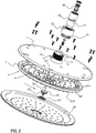
Fig. 2 is a three-dimensional decomposition diagram of the showerhead of quickly discharging residual water according to the specific embodiment. -
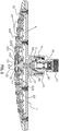
Fig. 3 is a cross-sectional view of the showerhead of quickly discharging residual water when the water is closed in the specific embodiment. -
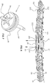
Fig. 4 is a cross-sectional view of the showerhead of quickly discharging residual water when the water is flowing in the specific embodiment, the arrows in the figure indicate the flow. -
Fig. 5 is a cross-sectional view of the showerhead of quickly discharging residual water when the water is cut off, some arrows in the figure indicate water flow and some arrows indicate air flow. -
Fig. 6 is a partial enlargement diagram ofFig. 5 . -
Fig. 7 is a three-dimensional schematic diagram of the valve core of the showerhead of quickly discharging residual water in the specific embodiment. - Please refer to
Fig. 1 to 7 , a showerhead capable of quickly discharging residual water, comprising aconnection base 1, asurface cover assembly 2 and avalve 3. - The
connection base 1 is provided with aninlet waterway 11 which can connect the external water supply source. Theconnection base 1 and thesurface cover assembly 2 are mounted together, and there is awater outflow cavity 4 between them, such as fixed seal assembly, rotary seal assembly, swing seal assembly or sliding seal assembly, etc. In the figure, the fixed seal assembly is taken as an example. Theinlet waterway 11 is connected to thewater outflow cavity 4. - The
surface cover assembly 2 is provided withwater discharging hole 23 and includes asurface cover body 21 and a wateroutflow surface cover 22 mounted on theconnection base 1. The mounting is fixedly sealed as described above. Thesurface cover body 21 is fabricated from hard materials, such as plastics, and the wateroutflow surface cover 22 is fabricated from silica gel. Thesurface cover body 21 is provided with aconcession hole 211 through the bottom surface; the wateroutflow surface cover 22 is provided with water outflow hole runs through the top and bottom surface. The lower circumference of the water outflow hole extends downward to form awater outflow port 221, and the upper circumference of the water outflow hole extends upward to form a water blockingperipheral wall 222. The water outflow surface cover22 is attached to the topsurface cover body 21 and thewater outflow port 221 adapts downward through the concession hole211 of thesurface cover body 21 and extends below thesurface cover body 21. The water outflow hole of the water outflow surface cover is provided with a water blockingperipheral wall 222. After the water is cut off, the residual water above the water outflow surface cover is blocked by the water blocking peripheral wall and cannot flow out from the water outflow port, and the residual water is discharged through the water discharging hole, because the water discharge area of the water discharging hole is relatively large enough to speed up the discharge, and avoid the slow dropping. - The
water discharging hole 23 is located in the center ofsurface cover assembly 2, and the water inlet of thewater discharging hole 23 is not higher than the top of the water outflow surface cover22, so that the water above the water outflow surface cover22 can be quickly discharged through thewater discharging hole 23 to avoid the occurrence of residual water. The specific structure of thewater discharging hole 23 is as follows: Thesurface cover body 21 is provided with the first throughhole 212 running through the top and bottom, thesurface cover 22 is provided with the second throughhole 223 running through the top and bottom. The first throughhole 212 and the second throughhole 223 are matched and thewater discharging hole 23 includes the first throughhole 212 and the second throughhole 223 mentioned above. Best of all, the top of thesurface cover body 21 is convexly provided with a convex ring wall213 , which surrounds the first throughhole 212 , the second throughhole 213 of the wateroutflow surface cover 22 is adapted to fit outside the convex ring wall213, and the top surface of theconvex ring wall 213 is not higher than that of the wateroutflow surface cover 22,it is convenient to assemble the water outflow surface cover and the surface cover body, and it is convenient to cooperate with the valve to control the water discharging hole to open and close. - The
valve 3 and thewater discharging hole 23 are combined to close thewater discharging hole 23 when the water is flowing and open thewater discharging hole 23 when the water is cut off. When thewater discharging hole 23 is opened, the residual water in thewater outflow cavity 4 is discharged from thewater discharging hole 23. In this embodiment, thevalve 3 and the first throughhole 212 cooperate to control the opening and closing of the first throughhole 212 through thevalve 3. For example, the inner wall of the first throughhole 212 is provided with a large upper and small lowertapered wall 214, through thevalve 3 to achieve sealing by the tapered wall, through the valve away from the tapered wall to open. In specific structures: The water outflow of theinlet waterway 11 extends inward to form a supportingplate 13; thevalve 3 includes avalve core 31, avalve stem 32 fixed on the top of thevalve core 31 and anelastic body 33. The valve stem 32 passes through the supportingplate 13 from bottom to top and the upper end of thevalve stem 32 is fixed with abaffle 34. Theelastic body 33 sleeves thevalve stem 32 and is supported between thebaffle 34 and the supportingplate 13. Thevalve core 31 is connected to the connection base1 and can move from the upper position to the lower position relative to connection base1. The water force acts on thevalve core 31 to move thevalve core 31 from the upper position to the lower position when the water is opened, while theelastic body 33 acts on thevalve stem 32 to reset thevalve core 31 to the top when the water is cut off. When thevalve core 31 is in the upper position, thevalve core 31 is away from thewater discharging hole 23 to open thewater discharging hole 23, and when thevalve core 31 is in the lower position, thevalve core 31 cooperate with thewater discharging hole 23 to close thewater discharging hole 23. The center of the bottom surface of thevalve core 31 is fixed with acolumn rod 35 and a plurality ofdrainage sheets 36 fixed to thecolumn rod 35. Thedrainage sheets 36 are also fixed to the bottom surface of thevalve core 31. The width of the bottom surface of thedrainage sheets 36 from the bottom of thevalve body 31 are gradually reduced, and the side wall of thedrainage sheets 36 away from thepole 35 are a curved wall. - According to the need, the connection base1 is provided with
aventilation passage 12 run through inside and outside of the connection base1. The connection base is provided with a foaming mechanism, and theventilation passage 12 is the suction passage of the foaming mechanism. In this embodiment, theconnection base 1 is convexly provided with aconnection ring wall 14 surrounding the inlet waterway. Theconnection ring wall 14 can be assembled and fixed with a fixed joint 15 and abushing 16. Through cooperation of thebushing 16, theconnection ring wall 14 and the fixed joint 15, a spherical joint 17 is connected. The spherical joint 17 is provided with aninner sleeve 18, and the foaming mechanism is arranged in spherical joint 17 andinner sleeve 18. - According to need, the
surface cover assembly 2 can also include a decorative cover24, which is provided with a first through hole aligned to concession hole211, is provided with a second through hole corresponding to the first throughhole 213, and the water outflow port also passes through the first through hole. The discharging hole also a second though hole. - According to need, in order to enhance the sealing performance, it is preferable that the valve core casing is provided with a sealing
ring 37, such as a y-ring, and the y-ring and the water discharging hole are in contact with each other to achieve sealing. - As shown in
Fig. 3 , in the initial state, the showerhead has no water supply, thevalve core 31 is in the upper position under the action ofelastic body 33 such as spring, the valve core is far away from the water discharging hole, and the water discharging hole is open. As shown inFig. 4 , thevalve core 31 moves downward to the lower position under the action of water pressure. The elastic body is in the state of compressed energy storage. The valve core contacts with the tapered wall of the water discharging hole to seal. The water discharging hole is closed. The water outflow cavity is filled with water, and the water is normally discharged from the water outflow port. As shown inFig. 5 , after water shutdown, the hydraulic pressure is eliminated or reduced, the energy storage of elastic body is released, the valve core restores to its initial state under the action of elastic body, that is, it is in the upper position, and the water is discharged from the water discharging hole. Moreover, an air ventilation passage is provided, air enters the outlet cavity, which makes the pressure in showerhead cavity keep balance with the atmospheric pressure, and water rapidly flows out from the middle water discharging hole under the action of gravity. It can stop dripping quickly after drainage. - As mentioned above, it is only a better embodiment of the present invention, so the scope of embodiment of the present invention cannot be limited accordingly. That is, the equivalent changes and modifications made according to the patent scope and description content of the present invention should still be within the scope of the present invention.
- The invention provides a showerhead capable of quickly discharging residual water, when the water supply is off, the residual water on the water outflow surface cover cannot flow out from the water outflow port due to the blocking of the water blocking peripheral wall, and the residual water will quickly converge along the water outflow surface cover towards the water discharge hole and quickly discharge out from the water discharge hole, avoiding water dropping. The design of the invention is ingenious, and the application range is wide, has good industrial practicability.
Claims (13)
- A showerhead capable of quickly discharging residual water, comprising a connection base (1), a surface cover assembly (2) and a valve (3), the connection base (1) and the surface cover assembly (2) being assembled together and a water outflow cavity (4) being provided therebetween; the surface cover assembly (2) is provided with a water discharge hole (23) and comprises a surface cover body (21) and a water outflow surface cover (22) which are mounted and connected onto the connection base (1); the water outflow surface cover (22) is provided with a water outflow hole of which the top face and the bottom face are in communication; the lower periphery of the water outflow hole extends downwards to form a water outflow port (221), the water outflow surface cover (22) is attached against the upper face of the surface cover body (21) and the water outflow port (221) passes through the surface cover body (21); wherein: the upper periphery of the water outflow hole extends upwards to form a water blocking peripheral wall (222); the valve (3) cooperates with the water discharge hole (23) so as to close the water discharge hole (23) when the water supply is on and to open the water discharge hole (23) when the water supply is off; when the water discharge hole (23) is opened, the residual water in the water outflow cavity (4) is discharged from the water discharge hole.
- The showerhead capable of quickly discharging residual water according to claim 1, wherein: the connection base (1) is provided with an inlet waterway (11) capable of connecting an external water supply source, and the inlet waterway (11) is connected to the water outflow cavity (4); the surface cover body (21) is provides with a concession hole (211) running through the top and bottom of the surface cover body (21), and the water outflow port (221) adapts downward through the concession hole (211) of the surface cover body (21) and extends below the surface cover body (21).
- The showerhead capable of quickly discharging residual water according to claim 1, wherein: the connection base (1) is provided with a ventilation passage (12) penetrating inside and outside.
- The showerhead capable of quickly discharging residual water according to claim 3, wherein: the connection base (1) is provided with a foaming mechanism, and the ventilation passage (12) is the suction passage of the foaming mechanism.
- The showerhead capable of quickly discharging residual water according to claim 1, wherein: the water discharging hole (23) is located at the center of the surface cover assembly (2).
- The showerhead capable of quickly discharging residual water according to claim1, wherein: the inlet of the water discharging hole (23) is not higher than the top of the water outflow surface cover (22).
- The showerhead capable of quickly discharging residual water according to claim 1, wherein: the surface cover body (21) is provided with a first through hole (212) running through the top and bottom surface , the water outflow surface cover (22) is provides with a second through hole (223) running through the top and bottom surface, the first through hole (212) and the second through hole (223) are matched and the water discharging hole (23) includes the first through hole (212) and the second through hole (223) mentioned above.
- The showerhead capable of quickly discharging residual water according to claim 1, wherein: the top of the surface cover body (21) is convexly provided with a convex ring wall(213), which surrounds the first through hole(212), the second through hole (213) of the water outflow surface cover (22) is adapted to fit outside the convex ring wall(213), and the top surface of the convex ring wall (213) is not higher than that of the water outflow surface cover(22).
- The showerhead capable of quickly discharging residual water according to claim 7, wherein: the valve (3) cooperates with the first through hole (212) to control the opening and closing of the first through hole (212) through the valve (3).
- The showerhead capable of quickly discharging residual water according to claim 8, wherein: the inner wall of the first through hole (212) is provided with a large upper and lower tapered wall (214).
- The showerhead capable of quickly discharging residual water according to any of claim 1 to 10, wherein: the valve (3) comprises a valve core (31), a valve stem (32) fixed to the top of the valve core (31) and an elastic body (33) connecting the connection base (1) and the valve stem (32): the valve core (31) is connected to the connecting base (1) and can move between the upper position and the lower position relative to the connecting base (1), when the water is flowing, the hydraulic force acts on valve core (31) and make the valve core (31) move from the upper position to the lower position, the valve core (31) cooperates with the water discharging hole (23) to close the water discharge hole (23); when water is cut off, the elastic body (33) acts on the valve stem (32) to reset the valve core (31) to the upper position, and the valve core (31) is away from the water discharging hole (23) to open the water discharging hole (222).
- The showerhead capable of quickly discharging residual water according to claim 11, wherein: the center of the bottom surface of the valve core(31) is fixed with a column rod (35) and a plurality of drainage sheets(36) fixed to the column rod(35), and the drainage sheets (36)are also fixed to the bottom surface of the valve core(31), and the width of the drainage sheets (36)to the bottom surface of the valve core (31) is gradually reduced from the bottom end.
- The showerhead capable of quickly discharging residual water according to claim 1 or 3 or 4 or 5 or 6 or 7 or 8 or 9 or 10, wherein:the connection base (1) is provided with an inlet waterway (11) capable of connecting an external water supply source, and the inlet waterway (11) is connected to the water outflow cavity (4), the water outlet of the inlet waterway (11) extends inwardly to form a supporting plate (13); the surface cover body (21) is provides with a concession hole (211) running through the top and bottom of the surface cover body (21), and the water outflow port (221) adapts downward through the concession hole (211) of the surface cover body (21) and extends below the surface cover body (21);the valve (3) comprises a valve core (31), a valve stem (32) fixed on the top surface of the valve core (31) and an elastic body (33), which passes through the supporting plate (13) from bottom to top and the upper end of the valve stem (32) is fixed with a baffle (34), the elastic body (33) sleeves the valve stem (32) and is supported between the baffle (34) and the supporting plate (13), and the valve core (31) is supported between the baffle (34) and the supporting plate (13), the valve core is connected to the connection base (1) and can move between the upper position and the lower position relative to the connection base (1): when the water is flowing, the hydraulic force acts on the valve core (31) to make the valve core (31) move from top position to bottom position, and valve core (31) cooperates with the water discharging hole (23) to close the water discharging hole (23); when the water is cut off, the elastic body (33) acts on the valve stem (32) to reset the valve core (31) to the upper position, and the valve core (31) is away from the water discharging hole (23) to open the water discharging hole (222).
Applications Claiming Priority (3)
| Application Number | Priority Date | Filing Date | Title |
|---|---|---|---|
| CN201611175809.3A CN108607699A (en) | 2016-12-19 | 2016-12-19 | Residual water arranges shower soon |
| CN201621393424.XU CN206483591U (en) | 2016-12-19 | 2016-12-19 | A kind of residual water arranges gondola water faucet soon |
| PCT/CN2017/078719 WO2018113129A1 (en) | 2016-12-19 | 2017-03-30 | Showerhead capable of quickly discharging residual water |
Publications (2)
| Publication Number | Publication Date |
|---|---|
| EP3556470A1 true EP3556470A1 (en) | 2019-10-23 |
| EP3556470A4 EP3556470A4 (en) | 2020-08-19 |
Family
ID=62624193
Family Applications (1)
| Application Number | Title | Priority Date | Filing Date |
|---|---|---|---|
| EP17883763.9A Withdrawn EP3556470A4 (en) | 2016-12-19 | 2017-03-30 | Showerhead capable of quickly discharging residual water |
Country Status (3)
| Country | Link |
|---|---|
| US (1) | US11014115B2 (en) |
| EP (1) | EP3556470A4 (en) |
| WO (1) | WO2018113129A1 (en) |
Families Citing this family (9)
| Publication number | Priority date | Publication date | Assignee | Title |
|---|---|---|---|---|
| USD934990S1 (en) * | 2018-09-21 | 2021-11-02 | Grohe Ag | Shower head |
| USD934994S1 (en) * | 2019-05-09 | 2021-11-02 | Fratelli Fantini S.P.A. | Shower head |
| USD960296S1 (en) | 2019-06-20 | 2022-08-09 | Kohler Co. | Shower device |
| USD960304S1 (en) * | 2020-01-15 | 2022-08-09 | Grohe Ag | Shower head |
| USD971377S1 (en) * | 2021-01-29 | 2022-11-29 | As America, Inc. | Showerhead |
| USD1012231S1 (en) * | 2021-09-29 | 2024-01-23 | Hansgrohe Se | Shower head |
| USD1012232S1 (en) * | 2021-09-29 | 2024-01-23 | Hansgrohe Se | Shower head |
| CN114653492B (en) * | 2022-03-21 | 2023-09-05 | 谷力(厦门)科技有限公司 | Shower head |
| USD1015483S1 (en) * | 2022-05-31 | 2024-02-20 | Xiamen Delmei Sanitary Ware Co., Ltd | Shower head |
Family Cites Families (9)
| Publication number | Priority date | Publication date | Assignee | Title |
|---|---|---|---|---|
| DE10313822A1 (en) * | 2002-12-12 | 2004-07-15 | Hansgrohe Ag | Shower head with air input, e.g. for personal hygiene, |
| TW200628111A (en) * | 2004-09-29 | 2006-08-16 | Toto Ltd | Showerhead |
| US8205812B2 (en) | 2005-10-06 | 2012-06-26 | Bowles Fluidics Corporation | Enclosures for multiple fluidic oscillators |
| US20110233301A1 (en) * | 2009-07-28 | 2011-09-29 | Bowles Fluidics Corporation (A Md Corporation) | Rain can style showerhead assembly incorporating eddy filter for flow conditioning in fluidic circuits |
| CN102366739B (en) | 2011-08-26 | 2013-08-28 | 厦门松霖科技有限公司 | Residual water drainage and water suction non-return mechanism |
| CN202238412U (en) * | 2011-08-26 | 2012-05-30 | 厦门松霖科技有限公司 | Residual water-discharging and air-breathing non-return mechanism |
| CN104096647B (en) * | 2014-07-24 | 2016-08-24 | 开平市德尔斐卫浴科技实业有限公司 | A kind of bathroom gondola water faucet structure |
| CN205341085U (en) * | 2016-01-11 | 2016-06-29 | 东莞市适意洁具有限公司 | Anti -drop shower head |
| CN105498995B (en) * | 2016-01-27 | 2018-04-13 | 江门市霏尼格斯淋浴制品科技有限公司 | A kind of shower apparatus |
-
2017
- 2017-03-30 WO PCT/CN2017/078719 patent/WO2018113129A1/en active Application Filing
- 2017-03-30 US US16/346,388 patent/US11014115B2/en active Active
- 2017-03-30 EP EP17883763.9A patent/EP3556470A4/en not_active Withdrawn
Also Published As
| Publication number | Publication date |
|---|---|
| EP3556470A4 (en) | 2020-08-19 |
| US11014115B2 (en) | 2021-05-25 |
| WO2018113129A1 (en) | 2018-06-28 |
| US20190255552A1 (en) | 2019-08-22 |
Similar Documents
| Publication | Publication Date | Title |
|---|---|---|
| US11014115B2 (en) | Showerhead capable of discharging residual water | |
| CN103505110B (en) | A kind of pilot valve switching mechanism and apply the shower system of this mechanism | |
| CN106140504B (en) | A method of combination shower and its switching water discharging | |
| CN203516897U (en) | Time delay automatic closing valve free from influence of impurities in water | |
| CN110076016B (en) | Waterway switching structure of shower head | |
| CN103920607A (en) | Anti-drop shower head | |
| WO2017024792A1 (en) | Dual volume flow rate switching device | |
| US9175780B2 (en) | Button switch three-way valve | |
| CN204583523U (en) | Anti-residual water structure | |
| CN203730777U (en) | Press type valve body structure and bidet using valve body | |
| CN204664500U (en) | Structure improved safety check | |
| CN111085358A (en) | Switching structure of water outlet device | |
| CN112642600A (en) | Water outlet device with water stopping and flow control functions | |
| CN205462804U (en) | Drip proof shower nozzle | |
| CN108532699B (en) | Rotary toilet control valve | |
| US20210197215A1 (en) | Waterway switching valve | |
| CN105457774B (en) | A kind of Anti-drip shower nozzle | |
| CN105927784B (en) | A kind of concealed fluid level control valve | |
| US20160362878A1 (en) | Device for Preventing Backflow | |
| KR101494646B1 (en) | Fountain nozzle | |
| CN102384293A (en) | Mechanical water-break automatic close valve | |
| CN207599068U (en) | A kind of magnetic push type delay-self-closing spool | |
| CN215172528U (en) | Fire control is with disjunctor check valve | |
| CN201031984Y (en) | Tap water safety valve | |
| CN218718981U (en) | Water outlet device |
Legal Events
| Date | Code | Title | Description |
|---|---|---|---|
| STAA | Information on the status of an ep patent application or granted ep patent |
Free format text: STATUS: THE INTERNATIONAL PUBLICATION HAS BEEN MADE |
|
| PUAI | Public reference made under article 153(3) epc to a published international application that has entered the european phase |
Free format text: ORIGINAL CODE: 0009012 |
|
| STAA | Information on the status of an ep patent application or granted ep patent |
Free format text: STATUS: REQUEST FOR EXAMINATION WAS MADE |
|
| 17P | Request for examination filed |
Effective date: 20190529 |
|
| AK | Designated contracting states |
Kind code of ref document: A1 Designated state(s): AL AT BE BG CH CY CZ DE DK EE ES FI FR GB GR HR HU IE IS IT LI LT LU LV MC MK MT NL NO PL PT RO RS SE SI SK SM TR |
|
| AX | Request for extension of the european patent |
Extension state: BA ME |
|
| DAV | Request for validation of the european patent (deleted) | ||
| DAX | Request for extension of the european patent (deleted) | ||
| A4 | Supplementary search report drawn up and despatched |
Effective date: 20200716 |
|
| RIC1 | Information provided on ipc code assigned before grant |
Ipc: B05B 1/30 20060101ALI20200710BHEP Ipc: B05B 7/00 20060101ALI20200710BHEP Ipc: B05B 1/18 20060101AFI20200710BHEP Ipc: B05B 1/32 20060101ALI20200710BHEP |
|
| GRAP | Despatch of communication of intention to grant a patent |
Free format text: ORIGINAL CODE: EPIDOSNIGR1 |
|
| STAA | Information on the status of an ep patent application or granted ep patent |
Free format text: STATUS: GRANT OF PATENT IS INTENDED |
|
| INTG | Intention to grant announced |
Effective date: 20221212 |
|
| STAA | Information on the status of an ep patent application or granted ep patent |
Free format text: STATUS: THE APPLICATION IS DEEMED TO BE WITHDRAWN |
|
| 18D | Application deemed to be withdrawn |
Effective date: 20230425 |